1
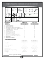
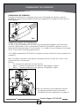
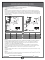
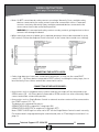
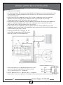
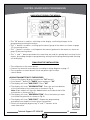
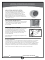
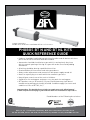
Length of operators.
Phobos BT is 32.48 inches and Phobos BT NL is 37.12 inches.
PHOBOS BT N AND BT NL KITS
QUICK REFERENCE GUIDE
•Products should be installed by a professional installer and all devices which are
part of the UL325 certification must be included.
•Automation should be installed on a gate which is moving freely. Any issue
with the smooth opening of closing of a gate will not be corrected by adding
automation.
•All wiring should be done by a qualified electrician.
•Read and follow all instructions and safety procedures.
•Always make adjustments and connections with power supply turned off.
•Never let anyone play on or walk within the automatic gate area.
•Keep all gate controls out of the reach of children.
•Stand clear of a moving gate and never cross the path of a moving gate.
•BFT products carry a 30 month (2 1/2 years) limited warranty from date of
manufacturing when professionally installed. Conditions apply (see terms and
condition of sales of BFT US, Inc.)
Important Note: This Quick Reference Guide is a complement to the official manual
(L from component list on page 3) part of the kit and in no circumstances supersedes it.
Proud Members of the Following Associations:
BFT U.S., Inc. 6100 Broken Sound Pkwy., N.W. Suite 14 Boca Raton, FL 33487, U.S.A.
US: 877-995-8155, Ph: 561-995-8155, Fax: 561-995-8160, www.bft-usa.com, [email protected]
TABLE OF CONTENTS
Phobos BT L Kit Components
................... 3
Technical Specifications
................... 3
Spare Parts
................... 4
Disengaging The Operator
................... 4
Brackets Installation (Pull To Open)
................... 5
Limit Switch Setting (Pull To Open)
................... 6
Brackets Installation (Push To Open) ................... 7
Limit Switch Setting (Push To Open)
................... 8
Wiring Instructions
................... 9–11
Battery Backup Installation
................... 12
Control Board Quick Programming
................... 13–14
Menu Flow Chart
................... 15–16
Wiring Diagram
................... 17
Troubleshooting
................... 18
Additional Information & Accessories ................... 2 19–20
Technical Support: 877-995-8155 PHOBOS BT N & BT NL COMPONENT LIST AND SPECIFICATIONS
A
B
E
J
C
F
D
G
K
I
H
L
ComponentsSingle KitsDual Kit s
Phobos BT N
(Ref. # R935246 00002)
Phobos BT NL
(Ref. # R935245 00001)
A: Post Mounting Bracket
1
B: Gate Mounting Bracket 1
C: Mounting Bracket Magnet Holder & Magnets
1
D: Kit Including: 1 Cover, 3 Screws, 1 Rubber Grommet,
1
1 Snap Ring, 1 Washer, 1 Release Key
E: Transmitter – Mitto 2 2
F: Pair Of Photocells – Fl 130B 1
G: Receiver Antenna – AEL 133
1
H: Control Board – Libra UL R 1
I: Operator – Phobos BT N Or Phobos BT NL 1
J: Cable – 3.3’ 3X16 AGW Cables For Operators 1
K: Warning Signs 2
L: Official Instruction Manual
1
(Ref. # R935246 00003)
(Ref. # R935245 00001)
2
2
2
2
2
1
1
1
2
2
4
1
Technical Specifications:
PHOBOS BT NPHOBOS BT N L
Power Supply:
Working Force:
Working Stroke:
Maximum Opening Angle:
Full Opening Time (At 90º):
Limit Switch:
Manual Operation:
Optimum Number Of Cycles Per Day:
Gate Length:
Gate Weight:
120V AC ± 10% - 60Hz
450 Lbs
11.6”
120º
15 Seconds
Incorporated
(Adjustble Magnetic)
Release Key
60
Up To 10’
Up To 550 Lbs
Technical Support: 877-995-8155 120V AC ± 10% - 60Hz
450 Lbs
18.5”
128º
23.5 Seconds
Incorporated
(Adjustble Magnetic)
Release Key
60
Up To 16.6’
Up To 550 Lbs
3 DISENGAGING THE OPERATOR
Disengaging the operator:
During the installation it is sometimes necessary to disengage the operator using the
provided CLS release key included in kit (D from component list on page 3). Please refer to
drawing below.
Fig. 1
Connecting cables to the operator:
In order to provide flexibility and avoid the use of junction boxes (please check with local
electrical requirements if this is allowed) the Phobos BT N and BT NL operators are not
delivered with mounted cables. The kit includes 1 or 2 cables (J from component list on page
3) of 3.3’ each with the following specifications:
3 X 16 AWG stranded wires (E172693) in a weather resistant insulation (J from component list
on page 3).
Note: the cables come with a red sleeve on the green wire on one side. This side is to be
connected to the control board.
Wiring:
1-
FC: Connect the white wire for limit switches
2-
Motor +: Connect the green wire for operator opening (pull to open)
3-
Motor -: Connect the black wire for operator closing (pull to open)
Fig. 2
Note: the connectors on the operator must be
closed and sealed with parts contained in
included kit (D from component list on page 3).
4 Technical Support: 877-995-8155 BRACKETS INSTALLATION (PULL TO OPEN)
• Inspect all gate components to insure proper operation.
• Gate must swing freely throughout its travel.
STEP 1
Position the post mounting bracket (A from component list on page 3) and gate mounting
bracket (B from component list on page 3) using the dimensions in the table depending upon
the operator used (Phobos BT N or Phobos BT NL) and depending upon the desired opening
angle (90 degrees or 110 degrees). Secure post bracket (A from component list on page 3) by
welding or bolting.
Fig. 3
Fig. 4
For opening of
90 degrees
Phobos BT N
Phobos BT NL
For opening of
110 degrees
Phobos BT N
Phobos BT NL
A
5 1/2”
7 1/2”
A
5”
5 1/4”
B
5 1/2”
7 1/2”
B
5”
5 1/2”
C
27 3/4”
32 1/2”
C
27 3/4”
32 1/2”
D
31 3/4”
36 1/2”
D
31 3/4”
36 1/2”
STEP 2
Position the gate mounting bracket (B from component list on page 3) so that the distance
between the post and gate bracket rotation points is 27 3/4 “ for Phobos BT N and 32 ½”
for Phobos BT NL (pull to open) with the gate fully closed. Secure gate bracket (B from
component list on page 3) by welding or bolting.
Note: Do not mount gate bracket (B from component list on page 3) on vertical pickets.
Instead, weld a plate or a bar horizontally across several pickets for reinforcement. Install
both the gate and post brackets in a position to ensure that the actuator is level.
STEP 3
Install the Phobos BT N or BT NL on the mounting brackets and secure with retainer C clips
provided in the kit.
STEP 4
Mount the Libra UL R or large enclosure box in close proximity to the Phobos BT N or BT NL
in accordance with local electrical regulation.
Technical Support: 877-995-8155 5 LIMIT SWITCH SETTING (PULL TO OPEN)
Fig.
FIG. 55
Fig.
FIG.66
Fig. 7
A
B
• Disengage operator with manual release key (D from component list on page 3).
• Locate the limit sensors located under the worm drive cover as shown in above Fig. 5 & 6.
• Position the gate in closed position (as shown on top of Fig. 5).
• Loosen the screw on the limit sensor at the end of the arm (as shown in Fig. 7), closest to
the gate bracket (B from component list on page 3).
• Slide the limit sensor at the end of the arm until you hear a faint “click” of the magnet
catching and then tighten the screw on the limit sensor.
• Loosen the screw of the limit sensor close to the main body of the operator and slide it all
the way backwards (against the main body).
• Manually move the gate to its fully open position (as shown on top of Fig. 6) in a slow and
even motion.
• Slide the limit sensor nearest to the motor until you hear a faint “click” of the magnet
catching and then tighten the screw on the limit sensor.
• Manually move the gate to its fully closed position (as shown on top of Fig. 5) in a slow and
even motion.
• Reengage the operator with the provided manual release key (part of Kit D from
component list on page 3).
6 Technical Support: 877-995-8155 BRACKETS INSTALLATION (PUSH TO OPEN)
• Inspect all gate components to insure proper operation.
• Gate must swing freely throughout its travel.
STEP 1
Position the post mounting bracket (not provided by BFT) and gate mounting bracket
(B from component list on page 3) using the dimensions in the table depending upon the
operator used (Phobos BT N or Phobos BT NL) and depending upon the desired opening
angle (90 degrees or 110 degrees). Secure bracket by welding or bolting.
Fig. 8
Fig. 9
For opening of
90 degrees
Phobos BT N
Phobos BT NL
For opening of
110 degrees
Phobos BT N
Phobos BT NL
A
5 1/2”
7 1/2”
A
5”
5 1/4”
B
5 1/2”
7 3/4”
B
5”
5 1/2”
C
16 1/4”
16 1/3”
C
16 1/4”
16 1/3”
STEP 2
Position the gate mounting bracket (B from component list on page 3) so that the distance
between the post and gate bracket rotation points is 16 1/4“ for both Phobos BT N and
Phobos BT NL (pull to open) with the gate fully closed. The closing limit switch must be
pulled all the way against the motor. Secure gate bracket (B from component list on page 3)
by welding or bolting.
Note: Do not mount gate bracket (B from component list on page 3) on vertical pickets.
Instead, weld a plate or a bar horizontally across several pickets for reinforcement. Install
both the gate and post brackets in a position to ensure that the actuator is level.
STEP 3
Install the Phobos BT N or BT NL on the mounting brackets and secure with retainer C clips
provided in the kit.
STEP 4
Mount the Libra UL R or large enclosure box in close proximity to the Phobos BT N or BT NL
in accordance with local electrical regulation.
Technical Support: 877-995-8155 7 LIMIT SWITCH SETTING (PUSH TO OPEN)
Fig. 10
Fig. 11
Fig. 12
A
B
• Disengage operator with manual release key (D from component list on page 3).
• Locate the limit sensors under the worm drive cover as shown in above Fig. 10 & 11.
• Position the gate in closed position (as shown on top of Fig. 11).
• Loosen the screw of the limit sensor close to the main body of the operator and slide it all
the way backwards (against the main body).
• Slide the limit sensor nearest to the motor until you hear a faint “click” of the magnet
catching and then tighten the screw on the limit sensor.
• Loosen the screw on the limit sensor at the end of the arm (as shown in Fig. 12), closest to
the gate bracket (B from component list on page 3).
• Manually move the gate to its fully open position (as shown on top of Fig. 10) in a slow and
even motion.
• Slide the limit sensor at the end of the arm until you hear a faint “click” of the magnet
catching and then tighten the screw on the limit sensor.
• Manually move the gate to its fully closed position (as shown on top of Fig. 11) in a slow and
even motion.
• Reengage the operator with the provided manual release key (part of Kit D from
component list on page 3).
8 Technical Support: 877-995-8155 WIRING INSTRUCTIONS
Refer to page 17 for terminal layout
IMPORTANT NOTE: For ease of wiring, the green terminal block sections 3-14, 15-20 & 2122 can be detached from the board by pulling them manually away from the base. Ensure
that the power is turned off before attaching and detaching the connectors and that the
terminal blocks are correctly aligned when reconnecting.
SINGLE OPERATOR INSTALLATION:
PULL TO OPEN
• Connect the red (+) wire of the Phobos actuator
arm to terminal 3 of the Libra control board.
• Connect the black (-) wire of the Phobos actuator
arm to terminal 4 of the Libra control board.
• Connect the white (FC: Limit Switch) wire of the
Phobos actuator arm to terminal 5 of the Libra
control board.
PUSH TO OPEN
• Connect the red (+) wire of the Phobos actuator
arm to terminal 4 of the Libra control board.
• Connect the black (-) wire of the Phobos actuator
arm to terminal 3 of the Libra control board.
• Connect the white (FC: Limit Switch) wire of the
Phobos actuator arm to terminal 5 of the Libra
control board.
DUAL OPERATOR INSTALLATION:
PULL TO OPEN
• Connect the red (+) wire of the Phobos actuator
arm to terminal 6 of the Libra control board.
• Connect the black (-) wire of the Phobos actuator
arm to terminal 7 of the Libra control board.
• Connect the white (FC: Limit Switch) wire of the
Phobos actuator arm to terminal 8 of the Libra
control board.
PUSH TO OPEN
• Connect the red (+) wire of the Phobos actuator
arm to terminal 7 of the Libra control board.
• Connect the black (-) wire of the Phobos actuator
arm to terminal 6 of the Libra control board.
• Connect the white (FC: Limit Switch) wire of the
Phobos actuator arm to terminal 8 of the Libra
control board.
Technical Support: 877-995-8155 9 WIRING INSTRUCTIONS
Refer to page 17 for terminal layout
CONNECTING THE power:
• It is recommended to use a separate line with its own
circuit breaker for the gate automation.
• Connect the line wire of the 110 volt power source
to terminal L of the Libra control board.
• Connect the neutral wire of the 110 volt power source
to terminal N of the Libra control board.
• Connect the ground wire of the 110 volt power source to
ground terminal of the Libra control board.
Wire not supplied
CONNECTING THE ANTENNA:
• Connect the antenna cable to the Libra circuit
board. Strip cable and connect the core wire to
terminal 23 and the shield wire to terminal 24.
Note: This terminal block is not removable. The
connection of the antenna is easier to complete
by removing the board from the small black
enclosure.
CONNECTING THE PHOTOEYE (THROUGH BEAM):
• Connect #1 & #2 of the photoeye receiver to
terminal 11 & 12 of the Libra control board.
• Connect #3 & #5 of the photoeye receiver to
terminal 15 & 18 of the Libra control board.
Remove jumper wire.
Wires not supplied.
• Connect #1 & #2 of the photocell transmitter to
terminal 11 & 12 of the Libra control board.
10 Wires not supplied.
Technical Support: 877-995-8155 WIRING INSTRUCTIONS
Refer to page 17 for terminal layout
• Note: On BFT control boards safety contacts are always Normally Close, multiple safety
devices connected to the same contact have to be connected in series. Command
contacts are always Normally Open; multiple command devices connected to the
same contact have to be connected in parallel.
WARNING: All command and safety contacts are dry contacts, giving tension to these
contacts will damage the board.
• When more than one set of photo eye is required, photoeyes have to be connected in series
(NC contact). Follow the diagram (install receivers on the same side to avoid cross talking):
CONNECTING THE SAFETY LOOPS:
• Safety loop detectors have to be connected as photoeyes, as they use the same PHOT
contact (15 – 18). Every device connected to PHOT contact, including the safety loops, has to
be a Normally Close contact and will be connected in series.
CONNECTING OTHER ACCESSORIES:
• Accessories such as telephone entry systems and free exit loops will be connected to the
OPEN contact (15 – 20). Every device connected to OPEN contact has to be a Normally Open
contact and will be connected in parallel.
• Accessories such as Single Button Control or external receiver contact will be connected to
the START contact (15 – 16).
The button will command the gate to:
OPEN/STOP/CLOSE in sequence (3 step logic ON)
OPEN/STOP/CLOSE/STOP in sequence (3 step logic OFF)
Note: START-CLOSE logic has to be set to OFF for the Single Button Control to work correctly.
For further details on programming the control board, refer to “Finalizing the installation” on
page 13.
Technical Support: 877-995-8155 11 OPTIONAL BATTERY BACK-UP INSTALLATION
• Unplug the main power.
• Cut wire going from JP2 connector on the board to 0V connector on the transformer. Strip
resulting ends. Cut wire going from JP5 connector to 25V connector on the transformer.
Strip resulting ends.
• Using a wire nut (not supplied) connect JP2, 0V and an additional wire (not supplied)
together. Connect other end of this additional wire on terminal # 3 on the SBS
charger board (part of BT Bat battery back-up system).
• Using a wire nut (not supplied), connect together transformer 25V wire and an additional
wire (not supplied). Connect other end of this additional wire to terminal # 4 on the
SBS charger (part of BT Bat battery back-up system).
• Using a wire nut (not supplied), connect together JP5 wire and an additional wire (not
supplied). Connect other end of this additional wire to terminal # 5 on the SBS charger (part
of BT Bat battery back-up system).
• Connect the batteries to terminal # 1 & 2
on the SBS charger (part of BT Bat battery
back-up system) as illustrated below.
• Check that polarity is respected with photocells and
accessories power supply: When in battery mode
#11 is + (positive), #12 is – (negative).
• On BFT photocells #1 is + (positive), #2 is – (negative):
• Check other accessories polarity according to the manufacturer’s installation manual.
12 Technical Support: 877-995-8155 CONTROL BOARD QUICK PROGRAMMING
NAVIGATING THROUGH THE MENUS:
• The “OK” button is used for: switching on the display, confirming changes to the
programming, entering the menus.
• The “+” button is used for: scrolling up the menus (go up in the menus as shown on page
15), increasing values.
• The “-” button is used for: scrolling down the menus (go down in the menus as shown on
page 15), decreasing values.
• The “+” and “-” buttons pushed at the same time are used for: getting back one level in the
menus, discarding changes to programming, exiting from the programming mode (turning
off the display).
FINALIZING THE INSTALLATION:
• Turn off power to the control board.
• Connect any external control device according to wiring diagram on page 17.
• Turn on power to control board. Check red power light on Libra
control board.
Fig. A
ADDING TRANSMITTERS TO THE RECEIVER
1. Turn on the display (by pressing twice the “OK” button).
2. Scroll down(“-”button) to “RADIO” menu and press “OK”.
3. The display will show “ADD START”. Press “OK”
4. The display will show “HIDDEN BUTTON”. Press the two front buttons
of the transmitter at the same time as shown on Fig. A.
Note: Older models will have the hidden button on the back side of the
transmitter as shown on Fig. C.
5. The display will show “DESIRED BUTTON”. Press the button you want
to activate the gate with as shown on Fig. B.
6. The display will show “ADD START” . Repeat the programming
procedure from step #3 to install other transmitters.
7. Switch off the display by pressing “+” and “-” buttons at the
same time twice.
Fig. B
Fig. C
Technical Support: 877-995-8155 13 CONTROL BOARD QUICK PROGRAMMING
SINGLE OPERATOR SETTING
Only when installing a single actuator (skip in case of dual operator installation):
1. Turn on the display (by pressing twice the “OK” button).
2. Scroll down (“-“ button) to “Logic” menu and press “OK”.
3. The display will show “TCA”. Scroll down to “1 Mot on”. Press “OK”.
4. The display will show “Off”. Press “+”.
5. The display will show “On”. Press “OK”.
6. Switch of the display.
WARNING: When installing a single operator, an improper setting in this logic will lead to
improper function of auto-close feature.
SETTING THE FORCE
1. Turn on the display (by pressing twice the “OK” button).
2. Scroll down (“-“ button) to “Autoset” menu.
The Autoset feature will automatically let the control board learn torques required to correctly
operate the gate.
WARNING: Once “OK” button is pressed the gate will start to move, obstruction detection is
disabled during Autoset. Be sure that no obstacle is within the working range
of the gate while Autoset is being performed.
NOTE: Autoset must be launched from a fully closed position. Autoset run from a different
position may lead to improper control board setting.
3. Press “OK”. The gate will open and close automatically.
4. O
nce the gate is closed the display will show “OK” (Autoset successful) press “OK” (if “KO”
is displayed, the Autoset failed, usually the cause of it is an improper setting for single
operator installation).
5. Turn off the display.
COMMON SETTINGS
Parameters:
TCA:Timer to close (sec.).
M1 fast time: Working time (sec) at full speed (motor 1) after this time motor 1 will proceed
at slow down speed).
M2 fast time: Working time (sec) at full speed (motor 2) after this time motor 2 will proceed
at slow down speed.
Slow speed:Slow down speed: 3 (25% of full speed)
WARNING! After changing the above parameters (except TCA) an Autoset is required.
Logics:
TCA:
Auto close enabled (ON)
3 step:
3 step logic (ON)
Ibl open:Commands during opening ignored (ON).
Photoc. Open:Photocells will be ignored while the gate is opening (ON)
1 mot on:Dual operator installation (OFF), single operator installation (ON).
14 Technical Support: 877-995-8155 MENU FLOW CHART
PARAMETER MENU
TCA (timer to close) [sec.]
(default 10 sec., min 3 sec., max 60 sec.)
Motor 1 torque [%]
(default 50%, min 1%, max 99%)
Motor 2 torque [%]
(default 50%. min 1%, max 99%)
Motor 1 torque slow-down [%]
(default 5%, min 1%, max 99%)
Motor 2 torque slow-down [%]
(default 5%, min 1%, max 99%)
Opening delay time [tenths of a sec.]
default 10 = 1 sec., min 10 = 1 sec., max 100 = 10 sec.)
Closing delay time [tenths of a sec.]
(default 10 = 1 sec. , min 10 = 1 sec., max 100 = 10 sec.)
Motor 1 normal speed time [sec.]
(default 15 sec., min 1sec., max 30 sec.)
Motor 2 normal speed time [sec.]
(default 15 sec., min 1sec., max 30 sec.)
Slow-down speed
0= Slow-down disabled
1 = 50% of normal speed
2= 33% of normal speed
3= 25% of normal speed
Zone (serial connection – requires SCS card)
(default 0, min 0, max 127)
LOGIC MENU
TCA (automatic closing)
Default: OFF, Enabled: ON, Disabled: OFF
3 STEP (3 step/4 step)
Default: OFF, 3 step: ON, 4 step: OFF
IBL OPEN (commands ignored on opening)
Default: OFF, Enabled: ON, Disabled: OFF
FAST CLS (closing on photoeye disengage)
Default: OFF, Enabled: ON, Disabled: OFF
PHOTOC. OPEN (photoeye ignored on opening)
Default: OFF, Enabled: ON, Disabled: OFF
TEST PHOT (photocell test – requires different wiring if ON,
see instruction manual for further details)
Default: OFF, Enabled: ON, Disabled: OFF
1 MOT ON (single operator installation)
Default: OFF, Single op. install.: ON, Dual op. inst.: OFF
BLOC PERSIST (lock hold - use only if positive stops installed)
Default: OFF, Enabled: ON, Disabled: OFF
START-CLOSE (terminal 16 as CLOSE)
Default: OFF, Term. 16: CLOSE: ON, Term. 16 START: OFF
FIXED CODE (fixed/rolling code receiver)
Default: ON, Fixed code: ON, Rolling code: OFF
RADIO PROG. (radio learn)
Default: ON, Enabled: ON, Disabled: OFF
MASTER (the board is a “master board” – requires SCS card)
Default: OFF, Master board: ON, Slave board: OFF
Warning: the logic MASTER has no relation to
single/dual operator installation, it is used only if
serial connection with multiple boards is required.
Technical Support: 877-995-8155 15 MENU FLOW CHART
RADIO MENU
ADD START
(Program a button of a remote
to activate the gate)
ADD 2CH
(No effect)
READ
(Check if a remote is in the memory of
the receiver and display button #)
EX:
02 t1 (remote #2, button #1)
ko (remote not in the memory)
ERASE 64
WARNING!
Removes all remote devices
from the receiver memory.
COD RX
Displays the receiver code
(required only if cloning remotes
is needed)
AUTOSET
It automatically sets the motor torque (Motor 1 torque, Motor 2 torque, Motor 1 slow down torque, Motor 2 slow down torque).
Note: If slow down is disabled or not reached slow down torque will not be set. After slow down adjustment Autoset has to be carried out gain.
WARNING!: obstruction detection is disabled during Autoset. Be sure that no obstacle is within the working range of the gate
while Autoset is being performed.
16 Technical Support: 877-995-8155 WIRING DIAGRAM
IMPORTANT NOTE: For ease of wiring, the green terminal block sections 3-14,
15-20 & 21-22 can be detached from the board by pulling them manually away from the
base. Ensure that the power is turned off before attaching and detaching the connectors
and that the terminal blocks are correctly aligned when reconnecting.
Single operator or
operator that moves
first on opening.
Operator that moves
second on opening.
24 Vdc/25 W max
24 Vac OUT (180 mA max)
24 Vac Vsafe OUT (180 mA max)
STROBE LIGHT / MAGNETIC LOCKS CONNECTION
(need to be powered with separate relay Ref: BFT-USS-PAM-2)
24 Vac power supply to accessories
24 Vac power supply to fail safe accessories
(requires different wiring – see instruction manual
for further details)
COMMON TERMINAL
START/CLOSE TERMINAL: opens-closes-stops (START) or always closes
(CLOSE) the gate depending upon the logic setting (default is START)
STOP & RESET TERMINAL: stops the gate and UL ALARM when opened
PHOTOEYE TERMINAL: stops the gate when opened, when closed back
continues opening (if gate opening) or reverses (if gate closing)
PHOTOEYE SELF TEST TERMINAL: failure check terminal for PHOTOEYE
terminal (requires different wiring – see instruction manual for details)
OPEN TERMINAL: opens the gate when closed (e.g. free exit or
telephone entry contact)
Note: while the alarm is active
the gate is stopped. Reset the
control board before
re-activating the gate.
UL ALARM: the contact closes after 2 consecutive obstruction detections
with no limit switch activation. Can be reset by opening the stop
contact or switching off the power supply.
Technical Support: 877-995-8155 17 TROUBLESHOOTING
FAULT
DIAGNOSTIC
THE RED LED ON
THE LEFT OF THE
DISPLAY IS OFF
OPERATOR DOES
NOT RUN
remote or single button
control (terminal
15-16) not working. No
relay clicking audible.
OPERATOR DOES
NOT RUN
Relay clicking audible
GATE OPENS BUT
DOESN’T CLOSE
GATE STOPS AND
REVERSES AFTER
STARTING TO MOVE
GATE DOES
NOT CLOSE
AUTOMATICALLY
POSSIBLE CAUSE
FIX
Power or transformer connection is loose.
Check power and transformer connections.
Main fuse (next to transformer primary) is blown.
Replace fuse.
Bad control board.
Replace control board.
Circuit breaker / main line faulty
Check circuit breaker status and main line
STOP
STOP contact is open (15 – 17).
Check STOP contact connections.
PHOT
PHOT contact is open (15 – 18).
Check PHOT connections or photoeye obstructed.
Check proper functioning of connected devices.
Display blank and STRT
displayed when hitting the
button
UL ALARM activated (21 – 22 contact closed).
Reset the board (open and close STOP contact
(15 - 17)) or switch off and back on the power. If a
battery back-up system is installed, it needs to be
disconnected to reset.
STRT not displayed when
hitting the button
Remote not programmed.
Program remote (see remote programming on
page 13).
Remote battery out of charge (LED off on the remote
when pressing button).
Replace battery.
Motor fuse blown.
Replace fuse
Bad control board.
Replace control board.
Wrong connection of the motor wires.
Check that the white wire is connected to terminals
# 5 (motor 2) and 8 (motor 1).
Bad control board.
Replace control board.
Bad motor.
Replace motor.
OPEN
OPEN contact (15-20) continuously closed (ex. open
button stuck).
Open the OPEN contact.
PHOT
PHOT contact is open (15 – 18). The gate opens
because photoeye is ignored on opening in the logic
setting.
Check PHOT connections or photoeye obstructed.
Check proper functioning of connected devices.
AMP displayed when
starting reversing
Torque setting too low.
Increase manually the torque (Motor 1 torque,
Motor 2 torque, Motor 1 torque slow-down, Motor
2 torque slow-down in parameters section) or run
another Autoset.
Obstruction present.
Remove obstructions.
STRT displayed when
giving the command
Automatic closing is disabled.
Set automatic closing (TCA in logics section) to ON.
00.XX
In a single operator installation, dual operator
installation has been set.
Set single operator installation (1 MOT ON in
logics section) to ON.
OPEN
OPEN contact (15-20) continuously closed (ex. open
button stuck).
Open the OPEN contact.
PHOT
PHOT contact is open (15 – 18). The gate opens
because photoeye is ignored on opening in the logic
setting.
Check PHOT connections or photoeye obstructed.
Check proper functioning of connected devices.
GATE RUNS TOO
SLOW
Working time at normal speed is set too low.
Increase working time at normal speed (Motor 1
normal speed time, Motor 2 normal speed time in
parameters section) to desired value.
GATE DOES NOT
SLOW DOWN
Slow down is disabled.
Activate slow down (SIow-down speed in
parameters section).
Working time at normal speed is higher than the time
required getting to the full opening/closing position.
Decrease working time at normal speed (Motor 1
normal speed time, Motor 2 normal speed time in
parameters section) to desired value.
18 Technical Support: 877-995-8155 ADDITIONAL INFORMATION AND ACCESSORIES
Fig. A
ADDING TRANSMITTERS TO THE RECEIVER
1. Turn on the display (by pressing twice the “OK” button).
2. Scroll down(“-”button) to “RADIO” menu and press “OK”.
3. The display will show “ADD START”. Press “OK”
4. The display will show “HIDDEN BUTTON”. Press the two front
buttons of the transmitter at the same time as shown on Fig. A.
Note: Older models will have the hidden button on the back side of
the transmitter as shown on Fig. C.
5. The display will show “DESIRED BUTTON”. Press the button you
want to activate the gate with as shown on Fig. B.
6. The display will show “ADD START” . Repeat the programming
procedure from step #3 to install other transmitters.
7. Switch off the display by pressing “+” and “-” buttons at the
same time twice.
Fig. B
Mitto 2 Ref: # D111837
Fig. C
Remote control replacement battery:
Battery type 23AE 12 volts (size: 1 1/8” length x 3/8”
diameter). Available at: Radio Shack, Walgreens, auto
parts store, electronics store, on the Web, etc…
Replacement fuses for Libra board:
Board’s fuse 1.25 AMP (1/4” diameter x 1.25” long)
Line’s fuse 2 AMP (1/4” diameter x 1.25” long)
Available at: Radio Shack, auto parts store, electronics
store, on the web, etc…
HomeLink compatibility:
BFT Integrated radio receivers operate with a frequency of 433 Mhz. HomeLink is compatible
with radio-frequency devices operating between 288 and 399 MHz (exclusive of the restricted
322-335 MHz range). Select 2007 and newer vehicles are compatible up to 433 MHz (exclusive
of the restricted 400-410 MHz range). If your vehicle is equipped with a new 433MHz
transmitter, please log on to www.bft-usa.com and go to Downloads to find the procedure to
follow.
If your vehicle is not compatible with 433MHz, the following items need to be ordered and
installed by your installer:
Receiver: Ref. # 109950
Transmitter (for programming only): Ref. # MSC308911
Technical Support: 877-995-8155 19 ADDITIONAL INFORMATION AND ACCESSORIES
Add an optional radio digital keypad:
For more convenience you may add an optional
Radio Digital Keypad available from BFT. No wiring
is necessary and it will be programmed as your
Mitto 2 remote control. It will give you 100 separate
programmable entry codes and can operate up to 10
different systems. Ask your installer for further details.
T-Box Ref. # P121019
Add an optional Battery back-up:
In an unlikely event of power failure, you may easily add
a battery back-up to your Phobos BT Gate System. Ask
your installer for further details. BT-BAT
Ref. # P125005
Emergency release of operator:
In case of power failure (if the system is not connected
to an optional battery back-up) the system can be
released with the provided CLS key as shown in the
drawing on the right. You may now operate the gate by
pushing it or pulling it manually in a slow motion.
CLS Ref. # D610180
NOTE: Remember to re-engage the locking device after
power resumes.
UL RESET PROCEDURE:
For safety reason, it is a UL 325 requirement to freeze the automation in case the gate
is obstructed twice in a row. In order to reset the system and have the automation
functional again, the main power needs to be shut off and switched on again. It may be
done at the circuit breaker if the installation has one. If the system is equipped with a
battery back-up, the battery needs to be disconnected prior to the power being reset.
Note: Please reconnect the battery once the system is functional again.
20 Technical Support: 877-995-8155