1
Safety
You are responsible for the safe and prudent operation of
your vessel. Your TR-1 Autopilot is a tool that will enhance
your capability to operate your boat and catch fish. It does
not relieve you from the responsibility for safe operation
of your vessel. You must avoid hazards to navigation and
never leave the helm unattended.
In case of autopilot pump failure or leakage, shut the valves located
on the front of the manifold see page 15.
Before starting the hydraulic installation, please verify the type of hydraulic
steering in the boat. If it does not match the hydraulic layouts in this manual,
call technical support for specific installation procedures.
NOTE:
Before proceeding with the installation, read these instructions thoroughly. TR-1 Autopilots cannot accept
responsibility for installations where instructions have not been followed, where substitute parts have been
used, or where modifications have been made to our products.
1
Contents
Section III: Troubleshooting........................31
1
3-4
5
6
7
Section IV: Changing Codes.......................32
Table of Setup Codes 33-35
GPS Connection Guide 36-39
Section V: Setup............................................29
8
40
Section I:Wireless Parts List................41-42
Check List 9
Gladiator Specifications 10
Prep for Installation 10-12
Mounting Considerations 11
Component Protection 12
hydraulic Connections 12
Magnetic Environment 12
System Maintenance 12
Pump Installation 13
Electronic Control Unit (ECU) 14
Compass Ball Installation 13
NMEA 0183 Connections 16
Non-compliant NMEA Devices 17
Shadow Drive Installation 20
Warning Horn Installation 18-19
Deckmount On/Off Switch 21
Handheld Installation 22
Tachometry Connections 23-24
Battery Connection 25
Bleeding Hydraulics 25
Section II:Introduction........................43
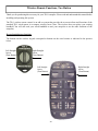
Remote Functions 44-46
Section III: Installation.......................46
Installation Considerations 46
Installation of Wireless 46
Section IV: General.............................47
Security Codes 47
Replacement Keypad 47
Changing Batteries 47
Warranty........................................................48
Section II: Setup..........................................29
Dockside Setup 26
Sea Trial Setup 27
Compass Calibration 27
Autotune 28
Set North 29
Fine Tuning 30
2
3
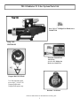
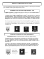
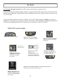
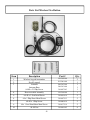
TR-1 Gladiator 2.1 Liter System Parts List
Pump Unit:
4 ea. #14 x 1” Phillips Pan Head screw
310-0072-18
Pump Unit:
120-2568-00
Electronic Control Unit:
120-2545-00
4 ea. #8 x 5/8” Phillips Pan
Head screw 310-0072-16
Compass Ball: 120-2250-00
3-ea. Pan head sheet metal
screws #8x1”: 310-0071-03
Compass Ball bracket
Compass Ball capture cage
Handheld: 120-2520-00
All screws and washers are included in the accessory pack
3
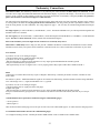
TR-1 Gladiator System Parts List
Accessory Pack 120-2570-00:
Tach Sensor Cable:
120-2510-00
10 ea.wire connectors: 290-0100-00
3 ea. wire ties Wht 11”: 305-0002-06
3 ea. Cable tie mounts
6 ea Black wire ties
3 ea. #8 x 5/8 Phil FT sts: 310-0072-16
Deckmount:
120-2515-00
2 ea. #4 x 3/8” Pan Head Screw
310-0072-03
Shadow Drive/Flow Switch 120-2580-00
Battery Cable with Fuse: 120-2530-00
Warning Horn:
120-2525-00
Compass Ball: 120-2250-00
3-ea. Pan head sheet metal screws #8x1”: 310-0071-03
Compass Ball bracket & capture cage: 120-2060-00
4
Handheld: 120-2520-00
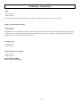
Single Helm Hydraulic Layout
BALANCED CYLINDER
Port Fitting
Starboard Fitting
Before starting the hydraulic installation, please
verify the type of hydraulic steering in the boat.
If it does not match the hydraulic layouts in this
manual, call TR-1 technical support for specific
installation procedures.
*Shadow Drive
!
1) Mount Horizontally and as level as possible
2) May be located in the Port or Starboard Hydraulic Lines
3) Use a length of hose between helm and Shadow Drive Valve
4) DO NOT install Valve directly to helm!
5) A Tee fitting MUST NOT be installed between helm and Shadow Drive Valve
P= Port
S= Starboard
R= Return
HELM
Pump &
Motor
Return line
P R S
��
��
��
��
*Shadow Drive
5
Dual Helm Hydraulic Layout
BALANCED CYLINDER
Port Fitting
Starboard Fitting
!
Before starting the hydraulic installation, please
verify the type of hydraulic steering in the boat.
If it does not match the hydraulic layouts in this
manual, call TR-1 technical support for specific
installation procedures.
P= Port
S= Starboard
R= Return
HELM
HELM
P R S
Pump &
Motor
Return line
P R S
��
��
��
��
*Shadow Drive
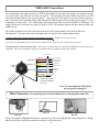
6
Wire Connectors
Electrical Layout
{
{
Yellow ( + )
White ( - )
(+)
GPS #1
( - ) NMEA out*
Blue ( + )
( + ) GPS #2
( - ) NMEA
NMEA In # 1
Compass
Ball
{
NMEA In # 2
Shadow Drive
Warning
Horn
Red
Brown
Black
Green
Black( - )
Blue (- )
Red ( + )
Orange ( + )
(+)
(-)
Red ( +)
Black (- )
NMEA Out
Chart Plotter
Overlay
NMEA IN*
}
}
}
Brown ( - )
Green (GND)
*Refer to your specific
electronics manual for
color codes or refer to
GPS connections on
pages 36-39
#4
Remote/
Handheld
Hydraulic Pump
& Motor
#3
Blue ( + )
Black ( - )
#2
#5
Port
Engine Tach
**
STBD
Engine
Tach
White ( + )
Orange and Black Twisted Wire
Red and Black Twisted Wire
Battery
#1
Deckmount
On/Off Switch
Red
Black
-
Brown ( - )
Tach Sensor
Do not extend
or splice these
wires
+
out*
Not normally Used
** Note: For diesel engine
installation, use the
engine(s) alternator(s)
tachometry output(s) as
input(s) to the autopilot
See Page 23-24
ECU
(Electronic Control Unit)
7
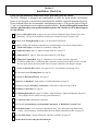
Chapter I
Gladiator Installation & Setup
................
This chapter will provide detailed information to accurately and successfully install the TR-1
Gladiator. If you have any questions please don’t hesitate to call technical support. 1-866-559-0229
Section I: Installation
Section II: Setup
Installation Checklist
Specifications
Preparation for Installation
Pump Unit
Electronic Control Unit (ECU)
Compass Ball
NMEA 0183
Non-Compliant NMEA Devices
Shadow Drive
On/Off Deckmount Switch
Warning Horn
Handheld
Tachometry Connections
Battery Connections
Bleeding Hydraulics
Dockside Setup
Sea Trial Setup
Set North
Section III: Trouble Shooting Guide
Section IV: Setup Codes
Section V: GPS Connection Guide
NOTE:
Before proceeding with the installation, read these instructions thoroughly. TR-1
Autopilots cannot accept responsibility for installations where instructions have not been
followed, where substitute parts have been used, or where modifications have been made
to our products.
8
Section I
Installation Check List
Please read all installation instructions before proceeding with the install!
The TR-1 Gladiator is designed and manufactured to meet the harsh marine environment.
However, no electronics can perform as intended unless installed, setup and maintained properly.
Please read and follow the recommended installation procedures. (The specific order of steps 411 can vary depending on certain conditions and the installer.) If you read through the instructions
and have questions about your specific installation, please don’t hesitate to call technical support
at 1-866-559-0229.
1) Refer to Hydraulic Layout on pages 6 for proper location of Hydraulic Pump, Shadow Drive Valve
and fittings. Verify that your hydraulic steering layout matches the layouts on pages 5 & 6.
2) Refer to the Wiring Diagram on page 7, for all electrical connections.
3) Before drilling and mounting components we recommend that you lay out all components first.
Check cable lengths. Extensions are available by calling TR-1
4) Mount the Pump. Page 13. Must be located within 20” of the ECU.
5) Mount the ECU. Page 14. Must be located within 20” of the Pump.
6) Mount the Compass Ball. Page 15. Must have access to make electrical connections
for NMEA, Shadow Drive, and Warning Horn. It must be mounted in the bracket in such a way that
the wires point directly down toward the water for proper orientation of the fluxgate compass.
7) Mount the Shadow Drive Valve. See pages 18 & 19. See Hydraulic Layouts page 5 & 6.
8) Mount and install Warning Horn. See page 20.
9) Mount the Deckmount Switch. See page 21.
10) Mount the Handheld. Flush mount, or Corded walkaround. See page 22
11) Install Autopilot Tachometry Connections. (Tach Sensor Cable) See page 23 & 24.
12) Battery Connections. See page 25.
13) Bleeding Hydraulics. See page 25. Helm(s), Autopilot Pump, Cylinder and Hydraulic lines need
to be purged of all air! (Follow steering system Instructions)
14) Check for leaks at all hydraulic connections.
15) Use a Corrosion Blocker on all installed Components. ie, Bo-Shield, Corrosion X etc.
16) Dockside Setup: Lock to Lock times, Helm displacement, Verify steering direction, RPM Source
Config., Verify tachometry, Transition RPM, and verify NMEA connections on GPS. See pages 26.
17) Sea Trial Setup: Compass Calibration, Autotune, Set North. See pages 27.
18) Re-check for leaks and hydraulic fluid levels
9
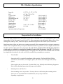
TR-1 Gladiator Specifications
Pump Set
15.375” L x 7.5”T x 7.5”W
ECU
6.5” H x 7” W x 2” D
Compass Ball
3.6”Diameter
HH/Remote
5” x 2.5 x 1”
Deckmount/On-Off
5/8” x 2.5 ”
Battery Cable
12 gauge
Tach Cable
Warning Horn
Shadow Drive
2-5/8” L X 1-1/4 Dia
Supply Voltage
11.5-14.0
In line fuse
Operating Ambient Temperature
Cable Length 20’
Cable Length 20’
Cable Length 10’
Cable Length 8’
Cable Length 13’
Wire Length 9’
Wire Length 9’
VDC
ATO 40 Amp
20 to 120 deg.F
Preparation For Installation
You will be hard mounting four components in your boat:1) The pump unit 2) The Deckmount switch 3) The
Compass Ball 4) The Electronic Control Unit (ECU). Other components to install include, Shadow Drive Valve,
Warning Horn, Battery Cable, Tachometer inputs, Handheld and optional is the NMEA (GPS) connections.
Spend some time to figure out where you are going to mount all of the components before you start to mount any
of them. Place components where you expect to mount them and verify you have access to, length, and routes for
the cables and hoses that connect the components. 10, 6, & 3 meter extension cables with the pico connectors
at both ends are available for extending the Handheld, Compass Ball, Deckmount, from TR-1. The Warning
horn and Shadow Drive may be extended using any 18-22 gauge wire. The Tach can be extended at the wire ends
by using shielded twisted pair, the cable end can be extended using a standard pico extension.
•
Tools Needed
Some tools will be required for installation of the autopilot. Drill and drill bits, Phillips
screwdriver, end wrenches, wire strippers, pliers, side cutters, hose cutter/pipe cutter, safety
glasses.
Other supplies that may be needed: Hydraulic fluid, rags, Helm/Hydraulic Bleeding Equipment.
Refer to helm bleeding instructions for proper tools required.
•
Mounting Screws & Wire Ties
Some mounting screws are provided. You may choose to drill and tap the mounting surface.
Some wire ties are included in the installation kit, but you may need more
depending on application.
10
Mounting Considerations, Protection, Hydraulic Connections, Magnetic
Environment, System Maintenance
Pump Unit: This pump unit is designed for cylinder or cylinders equilivant to 10 - 25 cubic inches only.
The Pump unit will need to be mounted within at least 20” of the ECU. It will need to be mounted in a horizontal position
to a solid surface. Do not lengthen or splice the #5 wire or the orange and black power wires. Do not use this pump
with an unbalanced cylinder.
Deckmount: The deckmount should be mounted on the dash near the helm.
Electronic Control Unit (ECU): The ECU will need to be mounted within 20” of the pump unit. Most all components in
the system connect to this unit, so considerations will need to be made due to access and cable lengths. (Extension cables
are available.) Note: Make note of Serial #’s and record them in the Manual.
Compass Ball: The Compass Ball needs to be located in the forward 1/2 of the boat. Mount it in a location where it will
not be disturbed or damaged, and protected against wash down or submergence. Mount the Compass Ball no higher than
10’ above the waterline. The Compass may be extended using extensions available from TR-1. The Compass ball will need
to be accessed for the Warning Horn, GPS and Shadow Drive valve connections. When making those connections, use the
blue connectors provided in the accessory pack.
Tach Sensor Cables: You will need to splice the end of the tach sensor lead to the tach sensor wire from your motor. You
may need to refer to a wiring diagram of your motor. The other wire connects to a clean ground. The other end will plug into
the ECU at connection # 2 as per wiring diagram. The tach may be extended using shielded twisted pair wire.
Shadow Drive Hydraulic Valve/Sensor: The Shadow Drive is an electronic bi-directional valve. It will need to be
mounted as shown in the system layout and can be extended using 18-22 gauge wire to make the electrical connections.
It needs to be mounted closer to the helm than to the pump unit, and will need to be mounted horizontally, and as level
as possible. (In a dual station helm, mount closer to and below the lowest helm.) Do not mount the Shadow Drive Valve
within 12” of any magnetic interference such as speakers or drive motors. Do Not Install valve directly to the fittings
at the back of the helm. Be sure to install a length of hose between the fitting at the helm and the Shadow Drive valve. TR-1
recommends a length of hose between Shadow Drive and any Tee. In a single helm installation, do not place a tee in the
line between the helm and Shadow Drive Valve. This is very important for the Shadow Drive feature to work correctly.
Air can and will get trapped in the valve during installation and bleeding. It’s very important to get all the air out of the
Hydraulic Lines, Helms, Pump, Cylinder (s) and The Shadow Drive valve.
Protection
Locate the Pump Unit, the ECU and the Compass Ball in a place where they will not be submerged or exposed to wash
down. Spray the installed components with a protective corrosion prohibitive like Bo-Shield or Corrosion X, etc.
Hydraulic Connections
Before starting the hydraulic installation, please verify the type of hydraulic steering in the boat. If it does not match the
hydraulic layouts in this manual, call technical support at 1-866-559-0229 for specific installation procedures. Examples
of steering systems that may need special instructions: Capilano, Hynautic, Latham.
Do not use Teflon tape on any hydraulic fittings. However, for leak free hydraulic system, we do advise you to use an
appropriate thread sealant such as, Loctite “Pro Lock” multipurpose anaerobic gel, part number 51604, or equivalent on all
pipe threads.
It is TR-1’s recommendation to only use hose with machine crimped on fittings, or field replaceable fittings that have
a minimum of 1,000 PSI rating.
11
It is recommended that before connecting the hydraulic lines to the pumpset, ensure all the hydraulic lines in the steering
system have been flushed and that the hydraulic oil is free of any contamination, which may enter the pumpset or Shadow
Drive valve and cause it to fail.
Air in the hydraulic system will cause the autopilot not to function properly. It’s important to bleed the system thoroughly.
Follow the steering manufacturers instructions on bleeding procedures before proceeding with installation. You can find
most of these instructions on the internet.
Hydraulic hoses must be protected from chafing, and installed in such a way that they will not come in contact with sharp
objects such as fasteners or edges. Hydraulic lines must be secured wherever possible to prevent hose vibration while the
autopilot hydraulic pump is running.
Magnetic Environment
The Compass Ball has a very sensitive compass and gyro in it. Do not mount the ball near magnetic material, magnets
(speakers and electric motors), or high current carrying wires. Movable or changing magnetic disturbances such as anchors,
anchor chain, and wiper motors, tool boxes and the autopilot pump should be kept at least 24” away. A small handheld
compass may help in locating a magnetic free environment.
The Shadow Drive must not be mounted within 12” of any magnetic material such as speakers or electric motors,
including the autopilot pump.
Strain Relief and Cable Protection
Do not let the connectors on the ECU be the sole support for the cables connected to them. Use tie wraps to tie the cables
down.
Do not run cables and hoses over sharp edges. Use grommets in through holes to protect cables.
Maintenance
Just like other electronic equipment, the TR-1 Gladiator should be protected against corrosion. Since most of the components
are out of sight, out of mind, you should coat all components with a spray on, electronic grade, protective corrosion inhibitor
like Bo-Shield, Corrosion X or equivalent. This should be done after installation, and repeated every six months for best
protection, more often if components and connections are exposed to salt water. Check battery connections and fuse holder
for corrosion, and make sure all connections are tight.
12
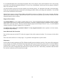
Installation Of Pump Unit
This pump unit is designed for cylinder or cylinders equilivant to 10 - 25 cubic inches only.
Hydraulic Pump and Motor Assembly: Mount the pump unit using the template provided. Mount the pump
to a solid surface using the #14 x 1” pan head sheet metal screws provided.
The pump unit connects to #5 at the ECU and the orange and black twisted wires connect to the orange and
black twisted wire connections at the ECU. Please refer to the electrical layout on page 8.
Install the pump unit within 20” of the pump unit.
Do not lengthen or splice the #5 wire or the orage and black power wires.
Do not use Teflon tape on any hydraulic fitting, but for a leak free hydraulic system, we do advise you to use
an appropriate thread sealant such as Loctite “Pro Lock” multipurpose anaerobic gell, part number 51604 or
equivalent on all pipe threads in the hydraulic system.
Do not use this pump unit with an unbalanced cylinder.
C1
C2
H1
H2
Return or Compensating Line
C1 and C2 connection on the pump connect to the cylinders Port and Starboard fittings.
H1 and H2 connection on the pump connect to the helms Port and Starboard fittings.
The Return or Compensating hose connects from the helm to the pump only.
13
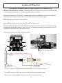
Installation Of Electronic Control Unit (ECU)
Electronic Control Unit (ECU): Mount the ECU using the template provided. Mount it to a solid surface using the four #8
x 5/8” Phillips Pan Head screws included in the accessory pack.
The ECU will need to be mounted within 20” of the pump unit. (Wire length only allows for 20” and cannot be lengthened) Most
all components in the system connect to this unit, so considerations will need to be made due to cable access and lengths.
Do not use any grease inside the pico connections on the ECU, the plugs will not fit properly, and you will end up with a
loose connection. Be sure to push the pico connectors firmly into place, and use wire ties to keep them from being pulled loose.
There are several places on the ECU to tie them.
Do not splice or lengthen the #5 wire or the black and orange twisted wire from the pump motor
Verify All Connections Prior to Applying power!
Hydraulic Pump
& Motor
#5
Keep Separated
Orange and Black Twisted Wire
Keep the orange and black twisted
wires on the pump motor separated
from the #5 wire coming from the
pump motor as shown.
Place a tie wrap around the Anderson connectors
as pictured above. It is important that this
procedure is done; the tie wraps will keep the
connectors from the possibility of coming apart
due to vibration.
14
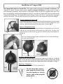
Installation of Compass Ball
The Compass Ball connects to #4 on the ECU. The Compass needs to be mounted in the front 1/2 of the boat. The
Compass ball contains a fluxgate compass which is sensitive to magnetic disturbances, be aware of what is around it
before mounting it permanently. Keep such items as, radio speakers, anchors, air ride seats, windshield wiper motors, tool
boxes, fire extinguisher, and the autopilot pump motor at least 24” away from the Compass Ball. These items will cause the
Compass Ball to malfunction. The Compass Ball contains a Fluxgate Compass and Gyro; it’s important that it is orientated
correctly in the bracket. Place the ball in the bracket as to allow the wires to come straight down as pictured in Fig.17.
Step one: Mounting the Compass Ball
Hold the mounting bracket in the desired position and drill through the holes into the mounting
surface. (Be sure that the wire coming out of the ball can exit the ball straight down.) Tap if
necessary. Install and tighten the three mounting screws as shown in Fig. 17.
Fig 13
Step two: Placing ball in bracket
Place the ball, wires down, into the bracket and capture it by snapping the cage over the ball,
sliding the tips of the cage between the ball and the legs of the bracket. Do the two legs
without the thumbscrew first. Rotate cage upwards to catch the bracket with the thumbscrew.
See Fig. 14.
Note: If you hang the mounting bracket upside down, be sure to run the cable through
the capture cage. See Fig. 15
Fig. 14
Fig. 15
Fig. 16
Step Three: Adjusting Compass Ball
Readjust the ball if necessary and fix it in position by tightening the thumbscrew. See Fig.16.
Make sure the that the wires from the Compass Ball are pointing straight down, out the
bottom; (toward the water) otherwise the Compass Ball will not work properly. See Fig. 17.
Step Four: Connection
Connect Compass Ball to the ECU at connection #4.
Fig.17
Do not mount the compass
near magnetic devices such
as radio speakers or electric
motors such as the autopilot
pump motor.
15
NMEA 0183 Connections
The Autopilot does not need to connect to a GPS for the autopilot to work, but if you want to use waypoint steering
you must connect to a GPS and set North see page 29. The Autopilot will accept NMEA input from two GPS
units and transmit NMEA to one receiving device. Only one of the GPS inputs is used for steering control at a
time. Selection of the controlling GPS is made through the NMEA source selection [code 34] (see pages 33-35 for
explanation of setup codes). The NMEA output port transmits the NMEA sentence $APHDG at 4800 baud. The
output refresh rate is selectable via [code 49] from 0 to 10 Hz. The Autopilot requires the data sentences RMC and
RMB to be on.
The NMEA conductors are in the cable stub at the base of the Compass Ball. (See Labels on Wires for
Identification) The wire color codes and signal names are shown in the wiring diagram below.
You must calibrate the compass ball and set North during Sea Trial of autopilot for it to work correctly.
Note: If you are using Radar Overlay, you may need to adjust code 168 in order for your overlay to line up correctly.
See pages 38-41 for a GPS Connection Guide. Please check your GPS manual for verification of NMEA 0183 connections on your
application. This is not a compatibility chart, but most all GPS units are compatible with the TR-1 Gladiator.
Wire Connectors
{
{
Yellow ( + )
White ( - )
(+)
GPS #1
( - ) NMEA out*
Blue ( + )
( + ) GPS #2
( - ) NMEA
NMEA Out
NMEA In # 1
Compass
Ball
{
NMEA In # 2
}
Fig. 18
out*
Not normally
Used
*Refer to your specific
electronics manual for
color codes
Note: For non-compliant NMEA 0183
devices, please read page 21
tor
Connec
Blue Connectors
Chart Plotter
Overlay
}Radar
NMEA IN*
}
Brown ( - )
Green (GND)
U #4
To EC
e
iv
Dr orn
ow g H
ad nin tors
h
S ar ec
To d W onn
an C
(+)
(-)
Red ( +)
Black (- )
(for connecting wires from the Shadow Drive, Warning Horn and GPS)
Fig. 19
Fig. 20
Twist wires together. (Fig 18) Slide the blue connectors over the wires (Fig 19) and crimp using pliers as in Fig
20. Be careful not to smash the connectors too hard, it will cut the wires.
16
Non-Compliant NMEA 0183 Devices
The TR-1 Autopilot is designed in conformance with the NMEA 0183 standard. The TR-1 will
communicate reliably and safely when connected to other devices that meet this standard with the
normal wire connections. Some manufacturers imply that they conform to the standard when in fact
they do not. Any device that requires a signal connection to ships ground is not in compliance
with the standard. The installer needs to confirm that connections to non-compliant devices are wired
in a fashion to ensure a safe and effective connection. In these cases the following procedure shall be
followed.
An indication that a device may be a non-compliant device is that the GPS signal is accepted by the
TR-1, but the RADAR shows no heading data, or has an intermittent heading input signal.
When connecting the NMEA heading output to a non-compliant NMEA device, the NMEA positive
signal from the TR-1 shall be connected to the receiver NMEA positive signal. The connection should
then be tested to see if communications have been established, that is to say, does the intended receiver
indicate that valid heading data is being received from the TR-1. If so then no other connections need
to be made.
If the data is not being received by the receiving device, try to connect the receiving device power
ground to the same power ground as the TR-1.
If this cannot be done, a last resort is to connect the power ground of the receiver to the green wire
ground connection of the TR-1 NMEA interface wires through a 125mA inline fuse. It is VERY
important that the grounds never be connected without the fuse as this can create a fire hazard
in the boat. Please contact TR-1 Autopilots technical support at 1-866-559-0229
for assistance.
When connecting the TR-1 NMEA input to a non-compliant device there should be no problem as
the NMEA standard allows this connection to be made safely, although in this case ground noise may
show up on the signal and cause intermittent problems. If these problems are experienced, a possible
solution is to be certain that the “signal ground” and the power ground are connected at the same
point.
17
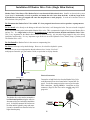
Installation Of Shadow Drive Valve (Single Helm Station)
Shadow Drive Valve/Sensor: The Shadow Drive is an electronic bi-directional valve. Install it as shown in the system
layout.Install it horizontally, as level as possible, and mount the valve lower than the helm. Avoid any loops in the
hydraulic lines, air may get trapped and cause the autopilot not to work properly. It needs to be mounted closer to
the helm than to the pump unit.
Do Not mount the Shadow Drive Valve within 12” of any magnetic interference such as speakers or pump motors.
Do Not Install valve directly to the fittings at the back of the helm, it will damage the helm. Be sure to install a length of
hose between the fitting at the helm and the Shadow Drive valve. TR-1 recommends a length of hose between Shadow Drive
and any Tee. In a single helm installation, do not place a tee in the line between the helm and Shadow Drive Valve.
This is very important for the Shadow Drive feature to work correctly. Air can and will get trapped in the valve during
installation and bleeding. It’s very important to get all the air out of the Hydraulic Lines, Helms, Pump, Cylinder(s) and
The Shadow Drive valve.
Do Not Install the Shadow Drive in the return or compensating line.
Do Not use teflon tape on hydraulic fittings. However, for a leak free hydraulic system,
we do advise you to use an appropriate thread sealant such as, Loctite “Pro Lock”
multipurpose anacrobic gel, part number 51604, or equivalent on all pipe threads.
Port Fitting
Return line
��
P= Port
��
R= Return
S= Starboard
��
*Shadow Drive
Starboard Fitting
Electrical Connections:
(Close up view)
To pump &
Cylinder
To Helm
The shadow drive valve must be mounted in a
level horizontal position using the cable ties
& mounts with screws included in installation
pack It should be mounted in-line between
the helm and the hydraulic pump and motor.
It must be mounted lower than the helm, but
higher than the pump.
Connect the red and black wires from the Shadow Drive Valve
to the Brown and Green wires located at the Compass Ball. See
page 8. Use the blue connectors in the accessory pack to make
those connections. See Fig 18-20 for instructions on blue
connectors. (Page 20).The wires can be extended using 18-22
Compass
gauge wire.
Ball
Shadow Drive
18
Red
Brown
Black
Green
#4
HELM
P R S
BALANCED CYLINDER
��
Pump &
Motor
Installation Of Shadow Drive Valve (Dual Helm Station)
Shadow Drive Valve/Sensor: The Shadow Drive is an electronic bi-directional valve. Install it as shown in the system
layout. Install it horizontally, as level as possible. In a dual helm, the shadow drive valve must be located behind and
closest to the lower helm, and closer to the helm than the pump. Avoid any loops in the hydraulic lines, air may get
trapped and cause the autopilot not to work properly. Air can and will get trapped in the valve during installation and
bleeding. It’s very important to get all the air out of the Hydraulic Lines, Helms, Pump, Cylinder(s) and The Shadow Drive
valve.
Do Not mount the Shadow Drive Valve within 12” of any magnetic interference such as speakers or pump motors.
Do Not Install valve directly to the fittings at the back of the helm, it will damage the helm. Be sure to install a length of
hose between the fitting at the helm and the Shadow Drive valve.
Do Not Install the Shadow Drive in the return or compensating line.
Do Not use teflon tape on hydraulic fittings. However, for a leak free hydraulic system, we do advise you to use an
appropriate thread sealant such as, Loctite “Pro Lock” multipurpose anacrobic gel, part number 51604, or equivalent on all
pipe threads.
BALANCED CYLINDER
P R S
Shadow Drive
Shadow Drive
Red
Brown
Black
Green
#4
Electrical Connections:
P R S
HELM
P= Port
R= Return
S= Starboard
Lower Helm
HELM
Upper Helm
Compass
Ball
Port Fitting
Connect the red and black wires from the
Shadow Drive Valve to the Brown and Green
wires located at the Compass Ball. See page
8. Use the blue connectors in the accessory
pack to make those connections. See Fig 1820 for instructions on blue connectors. (Page
20).The wires can be extended using 18-22
gauge wire.
��
Pump &
Motor
��
��
��
Starboard Fitting
(Close up view)
To pump &
Cylinder
To Helm
Fig 23
19
The shadow drive valve must be mounted in a
level horizontal position using the cable ties
& mounts with screws included in installation
pack See Fig. 23.
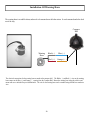
Installation Of Warning Horn
The warning horn is an audible alarm, and needs to be mounted near the helm station. It can be mounted under the dash
out of the way.
Compass
Ball
Warning
Horn
Black( - )
Blue (- )
Red ( + )
Orange ( + )
The electrical connections for the warning horn are made at the compass ball. The Black ( - ) and Red (+ ) wire on the warning
horn connect to the Blue (- ) and Orange ( + ) coming from the Compass Ball. Mount the warning horn using the cable tie and
mount with screw included in your installation kit. The wire for the warning horn can be extended using shielded two conductor
wire.
20
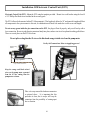
Installation of Deckmount On/Off Switch
If you choose to mount the On/Off Switch in an area that may be subject to salt water spray or wash down,
please install the switch using the waterproof bezel provided.
Installation of On/Off Switch Using Waterproof Bezel
Deckmount On/Off Switch: The Deckmount switch connects to #1 on the ECU. The deckmount should be mounted on
the dash near the helm. Use the #4 x 3/8” screws provided in the accessory pack.
If the material you wish to mount the Deckmount switch in is less than 1⁄4” thick: Drill a hole 15/32” diameter, and
perpendicular to the surface. Unscrew the waterproof bezel. Use the washers on the neck of switch to take up excess
space. Put the switch button, with washer, through the hole from back side, see Fig. 25. Slide on the face plate, see Fig.
26. Screw the waterproof bezel down over face plate firmly, Fig. 27, then drill and place screws into face plate to finish,
see Fig. 28.
If the surface you want to mount the Deckmount on is thicker than 1⁄4”, drill a 19/32” hole through the surface. Unscrew
the waterproof bezel from the top of the switch and remove the washers. Slide the switch all the way through the hole
from the backside of the panel. Apply some silicone sealer/adhesive to the barrel of the switch. Slide on face plate then
screw the waterproof bezel down firmly. It may be necessary to tape or otherwise hold the switch in place until the
sealer/adhesive sets.
Fig. 25
Fig. 26
Fig. 28
Fig. 27
Installation of On/Off Switch Using Standard Bezel
Deckmount On/Off Switch: The deckmount should be mounted on the dash near the helm.
If the material you wish to mount the Deckmount switch in is less than 1⁄4” thick: Drill a hole 15/32 Diameter
perpendicular to the surface. Unscrew the bezel. Use the washers on the neck of switch to take up excess
space. Put the switch button, with washer, through the hole from back side, see Fig. 9-a. Slide on the face
plate, see Fig. 9-b. Screw the bezel down over face plate firmly, then drill and place screws into face plate to
finish, see Fig. 9-c
If the surface you want to mount the Deckmount on is thicker than 1⁄4 inch, Drill a 19/32 hole through the
surface. Unscrew the bezel from the top of the switch and remove the washers. Slide the switch all the way
through the hole from the backside of the panel. Apply some silicone sealer/adhesive to the barrel of the
switch. Slide on face plate then screw the bezel down firmly. It may be necessary to tape or otherwise hold
the switch in place until the sealer/adhesive sets.
Fig. 9-a
Note: Deckmount
LED is very bright in
the dark. Mount the
DM switch in an area
where it will not shine
directly into the vision
of the boat operator.
Fig. 9-b
21
Fig. 9- c
Installation Of Handheld
The handheld connects to # 3 at the ECU. The handheld comes with a standard 18’ cable. It can be extended in length by
using extensions. These are available in three lengths; 10 ft, 20 or 30 ft.
Corded Mount:
Different options are available. TR-1 has
an optional clip than can be purchased
separately, Fig. 29.
Fig. 29
Mic Clip Part Numbers:
White 120-2043-03
Black 120-2043-02
Corded Mount
Flush Mount:
Remove the back cover of handheld. Using the back
of the handheld as a guide drill 2 1/4” holes into your
dash. Drill a 3rd 5/8” hole in the center of those holes
for the cord and pico connector to go through. Mount
the handheld using the existing nuts you removed
from the back. If your dash is too thick, you will need
to use thread extenders. See Fig. 30 & Fig. 31. Those
can be purchased separately.
Flush Mount
Thread Extender kit comes in (2)
lengths. 1/2” or 1”.
Extender Kit
Part Numbers:
1/2”: 120-2045-02
1” :120-2045-04
Fig. 30
Fig. 31
22
Tachometry Connections
Tach Sensor Cables: The tachometry connection is a very intricate part of the Gladiator and must always be connected. In most
cases this can be simply done behind the dashboard at the tachometer display or just before the display. You must always refer to the
engine’s owner’s manual or shop manual to locate the color codes and location of tachometry wiring. If you have any questions,
please don’t hesitate to call our Tech Support at 1-866-559-0229
You will need to splice the Positive end (s) of the tach sensor lead (s) to the tach sensor wire from your motor. Negative end (s) connect
to a clean ground. The other end will plug into the ECU at connection # 2. (You may possibly be able to pull and use a Black (-) wire
from the wiring harness on some Outboards) See wiring diagram on page 7. The wire may be extended using shielded twisted pair
wire.
For Single engines you will use the Blue (+) and the Black (-) wires. The Brown and White wire you will strip and twist together and
terminate with a wire connector.
For Two engines you will use the Blue (+) and the Black (-) on the Port Engine Tach and the Brown (-) and White (+) on the Starboard
engine. For three or more outboards; use the (outside) Port and Starboard engines.
Do not run tachometry wires near high current conductors or electrically noisy device.
This Chart is a Guide Only and is to help you with your TR-1 Gladiator Tachometer connections and should not be used as factual
information. Please check your specific motors manual for verification of the wire colors to make these connections on your motor.
I/O’s Gasoline
If you know for sure it is an analog tach signal
-Can take from the pulse or signal post off the tach gauge
If you know for sure it is digital tach signal
-Take from the pulse or signal post on the alternator -Use any engine ground OTHER than the alternator ground
If no post on the alternator to get signal from
-Take signal directly off coil, use negative side. -Use any engine ground. -May require an RC filter available from TR-1
Diesel
Connection to a Cummins Diesel 540 may require a “Magnetic Tach Pickup,” Cummins part number 3078155, available for order
from a dealer.
For Yanmar 6 cylinder – Model #6LPAM tach signal can be located in the bell housing. Find the terminals with the Orange and Black
wires. The Orange wire is (+) signal, and the Black wire is (-) ground.
If you know for sure it is an analog tach signal
-Can take from the pulse or signal post off the tach gauge
If digital tach signal
-Take from the pulse or signal post on the alternator- Use any engine ground OTHER than the alternator ground
If no post on the alternator to get signal from - You will have to use the wires from the tooth counter, (this will vary in color per
motor).
Yamaha Outboards, Except F350 or Outboards using the command link guages.
+ Green (positive)
- Black (negative)
Must be taken from the bullet plug (one will be open on each wire) in the cable bundle approx. 4-6 inches from the tach gauge itself.
For Yamaha F350 and others that use the command link guages:
Use a Digital to Analog converter. Yamaha part number MAR-6X6DA-C0-00. Available from a Yamaha dealer.
23
Tachometry Connections
Honda
+ Gray (positive)
- Black (negative)
On most Hondas the pulses per revolution to 2. For the 6 cyl VTEK it must be set to 1 (Use Setup Code 267)
Mercury (not applicable to Verados)
+ Gray (positive)
- Black (negative)
On Optimax motors: if your reading is incorrect and fluctuates up and down you must change the tach output to analog by taking the
cowling off the motor, finding the 3 gray wires under the alternator (2 will be connected together), unplug those two and moving the
plug from one wire to the open connector on the 3rd wire.
Evinrude E-Tech
+ Gray (positive)
- Black (negative)
Suzuki Outboards, Except 300HP
+ Yellow (positive)
- Black (negative)
Suzuki Outboards 300HP
Please contact product support
24
Battery Connections
Connections to the battery should be made last. Connect the ground side first. Connect the black (-) wire to the negative (-) side of the
battery first. Connect the orange (+) wire to the positive (+) side of the battery terminal. We prefer that the system is connected directly
to a battery, but if you are connecting to a terminal block or other source, the Gladiator needs a 40 amp supply. If the autopilot power is
taken from an accessory switch, be sure that the proper gauge of wire is used.
Note: Do not be alarmed if the connections sparks when connected to the battery, you are charging a capacitor inside the unit.
Do not cut out or eliminate the fuse portion on your battery cable, it is there to protect your system and will void your warranty
if it is removed.
The Battery cable is 8’ long. If you need to lengthen the battery cable, do so by following the table below for the proper gauge
wire. Be sure to include the fuse holder when extending wire.
Extended Length
Gauge of Wire Recommended
10’
12
15’
10
20’
10
25’
8
Bleeding Hydraulics
As with any hydraulic system, the air must be purged completely from All Hydraulic lines, Helms, Cylinders, Gladiator pump and
Shadow Drive Valve in order for the system to work properly. Failure to bleed the system properly and completely, will cause the system
not to work properly. See your steering system’s owner’s manual for proper bleeding instructions. Treat the Gladiator pump as the lowest
helm while bleeding the system.
You can download bleeding directions for most helm types from the internet.
Disabling the Shadow Drive Valve using code 367 ( See page 32 on how to change the Parameters) will make bleeding the system
much easier. Be sure the Shadow Drive is enabled again when you are done with bleeding.
Be sure to check for leaks at all Hydraulic Fittings; Pump, Helm, Cylinder, and Shadow Drive Valve.
Refer to the helm manufacturers instructions for the recommended fluid.
Recheck for leaks and check hydraulic fluid levels after Sea Trial.
25
Section II
Dockside Setup and Sea Trial Setup of Autopilot
Your autopilot needs to be setup and tuned to your boat dynamics and motor configuration. It is important to get the
autopilot operating the best in can. The Dockside Setup and the Sea Trial Setup are steps that must be followed to achieve
the best performance from the TR-1 Gladiator Autopilot. Have patience and try to do the Sea Trial Setup on a nice calm
day. Follow the directions below. These steps are in a sequence to help keep you from making any errors. If you have
any questions, please call us at 1-866-559-0229.
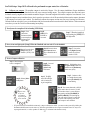
Dockside Setup: Steps 1-9 can be done at the dock before heading for open water.
1. Turn autopilot system on. Press the deckmount (on/off switch) on, the deckmount will blink slowly for 30 seconds during
startup. The system will automatically go into standby mode, and the deckmount will then blink rapidly. No functions are available
during startup. You will be using the handheld and deckmount switch to enter codes, change, and save the values of the parameters.
Parameters and their values are on the Table of Setup Codes, (Pages 35-37)
2. Lock to Lock times. Count the number of turns it takes your helm to go from lock to lock and adjust the parameter of
code 26 to match. (Factory default is set at 4.5) The value of code 26 can be seen in the blink code flashed on the up and down
arrow buttons on the handheld. Press and light up the [Setup] LED , press and light up numbers 2 & 6, [Code 26]. Press and hold the
[Select Load] (GPS) button. The number of turns is 1/10th of the blinked code + 1. Example: if the blinked code is 44 (The up arrow
will blink 4 and the down arrow will blink 4) the number of turns is (44 + 1)/10 = 4.5 turns lock to lock. To adjust the parameter, press
and light up the [Setup] LED , press and light up numbers 2 & 6, [Code 26]. Press the up and down arrows to adjust the parameter.
3. Helm displacement. The value of [Code 269] should be set to reflect the helm displacement. (Factory Default is set at 1.7). Press
and release [Setup] button. Press and light up [Code 269] on the handheld. By pressing and holding down the [Select Load] (GPS) button
on the handheld, the up and down arrows will blink to reflect the helm displacement code. The helm displacement is usually written on the
body of the helm pump. Example: The blinked code for a 1.7 cu in/rev helm would be 16, (the up arrow blinks once and the down arrow
blinks 6) since (16 +1)/10 = 1.7.
4. Verify the direction of steering is correct. Turn the autopilot on and switch from standby to autopilot. When the right straight
arrow turn button is pressed on the handheld remote, the motor should turn the boat to the right. When the left straight arrow turn button is
pressed on the handheld/remote, the motor should turn the boat to the left. If this is incorrect use [Code 249] for reversed hoses. Press and
release, and light up the [Setup] LED, press and light up [Code 249] on handheld, if the down arrow is lit, press the up arrow to reverse
hoses. If you change this setting, download changes into permanent memory by following step 8.
5. RPM Source Configuration. The default setting on the autopilot is set for a Single Engine. If you have twin engines or more,
you will need to change [Code 259] to match your motor configuration. Twin engines; Press, release and light up the [Setup] LED on
the handheld, press and enter [Code 259] on the handheld. Press the [Up Arrow] TWO (2) times which is setting the parameter to [(4)
Both]. See page 38 code 259 for more information.
6. Verify the autopilot tachometer (Tach Sensor Cable) is functioning properly. With the engine(s) running. Press, release
and light up the [Setup] LED on the handheld, and press and light up [code 35]. Press and hold the [Select Load] GPS button and you
should see the [Up Arrow] and [Down Arrow] LED’s blink your port engine’s RPM. For example, when the [Up Arrow] LED blinks
2 times and the [Down Arrow] LED blinks 5 times your engine is running at 2500 RPM. [Code 36] works the same way as code 35
for the starboard engine instead of the port engine. The autopilot tachometer system has a lower limit setting of 200 RPM. If needed,
adjusting [Code 267] (pulses per rev) to make your autopilot tachometer match the tach on your dashboard.
7. Transition RPM. This is the RPM at which your boat transitions from displacement to planing speed. [Code 348] is set to a factory
default of 3000 (2 blinks of the [Up Arrow] LED and 9 blinks of the [Down Arrow] LED +1). You should set it to your boat’s transition
RPM. (Example: Say that your planing speed is at 2500 RPM’s; With the [Setup] LED lit, press and light [code 348], since the factory
default is 3000 which is 2 blinks of the up arrow and 9 blinks of the down arrow (The value can be seen with the [Setup] LED lit, press and
hold the [Select Load] GPS , release the select load button, then click the down arrow 5 times; that will set your transition RPM’s at 2500.)
If you don’t know what the transition RPM is, you will need to do this as part of your Sea Trial Setup.
8. Download to permanent memory the parameters you have adjusted so far. (This must be done) With the [Setup]
LED lit, press and hold the GPS [Select Load] button - the [load] LED should illuminate on the handheld, while still holding
down the [Select Load] button, press and release the [Deckmount], on/off button quickly, then release the [Select Load]
GPS button.
9. Verify NMEA Connections: Verify that the NMEA connections for the GPS are functioning. Turn on the GPS.
With the Autopilot in [Standby], press and release [Setup] button on the handheld. Press and light up the number 4 and
the number 8 LED’s[ Code 48]. If the [up arrow] LED lights when you hold down the [Select Load] (GPS) button, the
autopilot does not acknowledge the validity of the GPS data.
26
Sea Trial Setup: Steps 10-15 will need to be performed on open water, free of obstacles.
10. Calibrate your compass. The autopilot compass is made with a fluxgate. Like all compass installations, fluxgate installations
are susceptible to local magnetic disturbances that will cause erroneous heading outputs. The autopilot computer can detect and correct
deviations caused by magnets and iron materials around the fluxgate- if the earths’ magnetic field near the compass isn’t too distorted. Even
though the compass corrects iron induced errors, don’t expect the correction to solve all ills associated with iron near the compass, placement
of the compass in an iron free area is critical. You should only calibrate the compass on calm water. Stay away from large steel structures.
Calibration will not work right if you try to do calibration with your boat on the trailer because the trailer is made with iron. Find some smooth
water where you can drive in circles without running into anything.
1. Turn System On. Autopilot will be in Standby [STBY Mode]
Step A. Press
and Release
Deckmount Switch
to turn autopilot on.
Deckmount will
begin to flash
Step B.
[STBY] LED
will blink for
30 seconds.
Step C. When the Autopilot is
done loading the [STBY] LED
will light solid.
2. Press, release and light up the [Setup] LED on the Handheld, and enter code 47 on the handheld.
Step A. Press and release
[Setup] button once to
illuminate [SETUP] LED.
Step B. Press and release
[Left Chevron] button
once to illuminate the #4
LED.
Step C. Press and re-
lease [Right Chevron]
button once to illuminate the #7 LED.
3. To start Compass calibration.
Step A. Start driving the
boat in a straight line.
Step B. Press and
HOLD the
[Select Load]
GPS button.
Step D. Release [Select
Load] button
Step E. The [UP]
arrow LED will light
solid. (Continue driving in a straight line.)
Step F. Continue to drive
in a straight line and watch
for the [UP ARROW] LED
to start blinking.
Step H. Turn at a rate that makes a full 360
degree turn in about 30 seconds. You will
need to make at least 3 or more full turns.
Keep turning until the [UP ARROW] &
[DOWN ARROW] LED’s both light up.
They will stay lit for about 5 seconds and
the system will completely power down.
Your compass is now calibrated.
Step G. When
the up arrow
starts blinking,
begin turning the
boat to starboard.
•
Step C. While holding down
the [Select Load] button. Press
and Release the [Deckmount]
button once quickly.
If Up and Down Arrows both blink continuously, compass calibration has failed - you must turn the system off by holding the
Deckmount On/Off button down in order to try calibration again. Make sure the compass is mounted at least 24” away from
any magnetic material, i.e. radios, speakers etc. Make sure it is orientated in the bracket correctly.
27
11. Restart the autopilot by pressing and releasing the Deckmount On/Off switch.
Autotune. The autopilot’s autotune function can really simplify the problem of adjusting the feedback gains. The autotuner
will adjust the gains well enough that you may not need to do any additional adjustments at all. You can adjust the autotune results after
autotuning if needed.
12.
In order to use the autotuner (or to tune the autopilot yourself), you must be in calm water with very little wind. You will let the autotuner
drive your boat for several minutes, so you need to have as much as one half to 1 full mile of clear water in front of you when you start
autotune. The autotuner will drive in a zigzag pattern and may not maintain the course you initially started on. You can abort autotuning
at any time by pressing any button on the remote or by pressing the deckmount switch, or by steering from the helm.
You will do autotuning at a fixed RPM, don’t change throttle settings once the autotuner has been started. (If autotune fails try it
again at a slower speed). Make sure the engine is trimmed all the way down and trim planes are fully retracted, and make sure the boat
isn’t listing. Don’t move around in the boat while autotune is underway. If your boat has a vee bottom and tends to roll a lot when the
rudder moves, you will get better autotuning results by doing autotune at lower RPMs than indicated above.
Step A. The autopilot must
be in standby. [STBY] LED
is illuminated.
Step B. Press, release, and
light up the [Setup] button
(left) LED will light.
Step C. Press and
release the [Left
Chevron] button
two times, and
light up #5 LED.
Step D. Press and
release the [Right
Chevron] button
two times, and
light up #8 LED.
Step E. Bring the engine(s) up to
speed (lower RPM not planing)
and steer the boat on a constant
heading.
Step F. To engage autotune:
Press and HOLD the GPS
[Select Load] button. While
holding down the [Select Load]
button, Press and release the
[Deckmount] button once
quickly. Release the [Select
load] button.
Step G. The Autotuner will zigzag the boat for 15 cycles. If you run out of room, abort the tuner and try it again in a spot where you
have more room to maneuver. You would like to see the time for one complete zigzag cycle to be between 3 and 6 seconds. Adjust RPM
up to reduce cycle time and adjust the RPM down to increase the cycle time. The zigzagging will stop when the autotuner is done. Be
prepared to regain control of the boat.
•
If the tune was good, both the [Up Arrow] LED and the [Down Arrow] LED will turn on solid for 5 seconds
•
If boat goes into circles, verify steering direction in step 4, page 28. (hoses could be reversed)
•
If the tune failed, both the [Up Arrow] LED and the [Down Arrow] LED will blink for 5 seconds.
•
If tuning conditions are real bad, the unit will simply go directly back to standby or shut down with no arrow
LED indications at all.
•
If the quality of the tune is suspect, the [Down Arrow] LED (only) will blink for 5 seconds; this may not be a
bad tune - so try it in autopilot mode first before tuning again.
When autotune is done, check out the steering performance at low and high speeds. If low speed performance isn’t too
good, try autotuning again. If, after several attempts at autotuning, the performance isn’t good you will need to resort to
the fine tuning procedure in step 15.
13. If the tune was good or suspect download to permanent memory the parameters you have adjusted so far
(autotune). With the [Setup] LED lit, press and hold the GPS [Select Load] button-the load LED should illuminate,
press and release the [Deckmount] button, then release the GPS [Select load] button.
Note: Press and release the [Setup] button to exit setup mode.
28
Set North
14. Set North. This needs to be done if any GPS or radar overlay functions are going to be used.
To run a GPS course requires that the autopilot compass is in agreement with the GPS’s magnetic map. You need to set North
with the pilot in standby mode. Setting North may require a significant amount of clear sea space in front of your boat (at least
1/2 to 3/4 of a mile).
Verify that the NMEA connections for the GPS are functioning. Turn on the GPS. With the Autopilot in [Standby], press and release
[Setup] button on the handheld. Press and light up the number 4 and the number 8 LED’s [Code 48]. If the [up arrow] LED lights when
you hold down the [Select Load] (GPS) button, the autopilot does not acknowledge the validity of the GPS data.
With The GPS Connected to Autopilot:
Step A. With the system in [STBY]
Step B. Press and release [Setup]
button once to illuminate (left) LED
Step C. Press and release [left chevron] button one time to illuminate
the #4 LED.
(You have now
selected code 48)
Step D. Press and release
the [Right Chevron] button
TWO times to illuminate
the #8 LED.
Step E. Run your boat at
planing speed at a
constant heading. You will
need at least 1/2 mile of hazard free water in front of you.
Step F. Press and HOLD the
GPS [Select Load] button. The
Load LED will illuminate.
Step H. Release the [Select Load] button, after [Load] LED diminishes.
The system will power down after North is set.
Step G. While holding down
the [Select Load] button. Press
and Release the [Deckmount]
button quickly.
29
15. Fine Tuning. (Optional)
If autotune did a pretty good job but you feel that the dead idle response of the pilot is a bit “twitchy”, try to eliminate the twitch by
increasing the Low RPM Limit [Code 357] to a few hundred RPM more than your dead idle RPM.
If you want to hold heading more aggressively at high speeds, try decreasing the High RPM Limit [Code 359] to a few hundred RPM
less than your engine RPM at high speed.
Your boat operates in two speed regimes, high speed planing and low speed displacement. The transition RPM, set with [Code 348],
is the autopilot’s boundary between the two regimes. The feedback gains are the low speed gains when operating below transition
RPM and high speed gains above the transition RPM. Autotune sets the gains for both speed regimes. This means that if you have
fine tuned the high speed gains and subsequently do another autotune, your fine tuned high speed gains will be lost. It’s good practice
to write down good gain settings in your manual so that you can always set your pilot up with them, if needed.
If you are fine tuning for low speed performance, be sure to tune with the sea state adjustment at it’s maximum value (the up
arrow LED should be lit when code 1 is selected). The tuning parameters low speed rudder gain, code 27. The low speed
Counter rudder gain, code 37. The tuning parameters for high speed are: The high speed rudder gain, code 29, the high
speed Counter rudder gain, code 39.
One good indicator of how well the pilot is tuned is how the boat returns to its “hold” heading after it has been disturbed or
knocked off the “hold” heading. If you disable the shadow drive with code 367, the autopilot and the helm will both control
the rudder at the same time. With the autopilot engaged, you can knock the heading off course by cranking the helm. When
you stop cranking, the autopilot will bring the boat back onto the “hold” heading. It is best to only upset the heading by
10 to 15 degrees for tuning purposes. When the gains are properly adjusted the autopilot will recover the “hold” heading,
after the upset, smoothly and without overshoot or oscillation and without undue rudder motion. As you adjust the gains
and watch the responses, you will quickly start to recognize when the response gets better and when it gets worse due to
the adjustments you make. When you get to the point that any adjustment to the gains makes the response worse, you have
(most of the time) done a good job of tuning. Sometimes one can find a combination of gains that performs smoothly and
is best combination in the region of gains where you have been tuning but there is a better set of gains in another region. If
the recovery from upset response you are getting is real slow, you probably found the wrong set of gains.
You can search for the right gain combination by alternately adjusting the rudder and counter rudder gains and testing the
responses after each adjustment. An example tuning sequence is as follows.
Initial rudder gain = 50 blinks. Initial counter rudder gain = 60 blinks
With pilot engaged and shadow drive disabled; disturb heading 10 degrees with the helm.
Watch the recovery
Increase rudder gain 5 clicks to 55
Disturb heading and watch the recovery
(Let’s say that the response was worse than the initial setting response, so we will try reducing the gain from the initial gain
setting to see if the response gets better or worse)
Decrease rudder gain 10 clicks to 45
Disturb heading and watch the recovery
(Let’s say that the response was better than the initial setting response)
We now know that the rudder gain is better than it was initially, so we now adjust the counter rudder gain
Increase the counter rudder gain to 65
Disturb and watch the response (Let’s say the response got better than the last response)
Go back to the rudder gain and try again. Keep up this process until you can’t improve the response.
As the performance gets better and better, you should make the incremental changes in gain smaller. In the above sequence
we were adjusting by 5 clicks, the next iteration might be better done at 4 clicks per trial.
See the notes following the Setup Codes section for codes 357 and 359 if you want to change the autopilot performance at
the RPM extremes.
NOTE: You must download the tune parameters before turning the autopilot off. With the [Setup] LED lit, Press
and hold the GPS [Select Load] button, the “load” LED will light, and then press and release the [Deckmount] On/Off
button, then release the [Select Load] Button
30
Section III
Trouble Shooting Guide
Autopilot does not hold heading.
1. Did you calibrate the compass?
a. Calibration must be done for the autopilot to work correctly. See pages 30
2. Has some kind of magnetic interference been introduced within 24” of the Compass?
3. Is Compass Ball and Bracket firmly mounted?
4. Are the wires pointing down out of the Compass Ball?
Compass Calibration fails. (If the up and down arrows both blink and the warning horn sounds, compass calibration has
failed-you must turn the system off by holding the Deckmount on/off button down in order to try calibration again.)
1. Check for magnetic disturbances
a. Be at least 24” from speakers, iron, radios, etc.
b. Do not calibrate compass on the boat trailer.
c. Be sure you are on smooth water.
d. Be sure that you continue turning starboard and do not turn back to the port.
Shadow Drive is being “false tripped” (autopilot disconnects when the helm is held steady)
1. May be due to air in the steering system.
a. Check for air, and re-bleed if necessary.
2. May be due to leakage of fluid past the helm pump lock valve.
a. Repair Helm valves.
3. Check location of Shadow Drive.
a. Must be located near the lowest helm, or last helm in line before the pump unit.
b. Must have short length of hose between helm and Shadow Drive.
c. Must be mounted horizontally and as level as possible.
d. Single helms must not have a Tee fitting before Shadow Drive Valve. See hyd Layout Pgs. 5 & 6.
Autotune fails. (Both the Up Arrow LED and Down Arrow LED will blink for 5 seconds)
1. Repeat the Autotune several times. If it fails each time, check the following.
a. Try finding smoother water if conditions are rough or windy.
b. Do not change throttle settings once the autotuner has been started.
c. Engine speed is too slow or too fast. (Set the engine speed such that the boat is running the
fastest speed it can before it starts to climb up on the bow wave.)
Autotune seems to be OK; then the next time you start autopilot it behaves as if it has not been tuned.
1. Did you download into permanent memory the autotune?
a. You must download the autotune before turning the autopilot off. (See page 28).
When starting Autotune the autopilot immediately turns in circles.
1. Hydraulic Hoses are backwards.
a. Use code 249 to reverse hydraulic hoses.
When in navigation mode the Autopilot heading does not match GPS heading.
1. Was North set on the Autopilot? To run a GPS Course requires that the autopilot compass is in agreement with
the GPS’s magnetic map.
a. See page 29.
2. Are the GPS outputs turned on and correctly formatted? NMEA 0183.
a. Sentences needed are RMB and RMC only. Un-needed sentences that are turned on may cause
autopilot to drop out of navigation mode.
31
Section IV:
How to Change Parameters of Setup Codes
Using the Table of Setup Codes on the following pages as a guide, follow the instructions below on how to
change any of the factory defaults. Remember-All changes must be downloaded and saved into permanent
memory for the changes to take effect the next time the system is turned on.
1. Autopilot must be in heading hold [Auto],[Standby], or [ GPS Track] mode before selection process can start.
( [Auto] LED solid on or [STBY] LED on solid or [GPS Track] LED solid on.)
2. Press and release the [Setup] Button. The [Setup] LED will illuminate to indicate the system is ready to take
setup commands (button pushes).
3. Select the Setup Function you want to use by pressing and releasing the buttons labeled 1 through 9 until the
appropriate LED’s are lit. (See the Table of Setup Codes and values changes on the following pages)
4. Increase an adjustable parameter one step by each press of the [UP Arrow] button. When the parameter is
adjusted to its maximum value, the [Up Arrow] LED will light. The parameter is adjusted and is in use by the
autopilot immediately.
5. Decrease an adjustable parameter one step by each press of the [Down Arrow] button. When the parameter
is adjusted to its minimum value, the [Down Arrow] LED will light. The parameter is adjusted and is in use by
the autopilot immediately.
6. You can stay in [Setup] and adjust more than one parameter.
7. Compass Calibration, and autotune are setup conditions that take the system over. You can get out of compass
calibration by turning the power off and can back out of autotune by pressing any button on the remote. Setting
compass North will cause the autopilot to turn off after the compass realigns. The button sequences for their
operation are given in the table of Setup Codes on the following pages.
8. To view the operating value of an adjustable parameter, enter its code per the Table of Setup Codes, then
press and hold the [Select Load] GPS button. The LED on the [Up Arrow] button will blink the number of tens
( or hundredths or thousandths) the parameter is set to and the LED on the [Down Arrow] button will blink
the number of ones (or tenths or hundredths) the parameter is set to. For example, if the parameter is set to a
current value of 15, the [Up Arrow] LED will blink once and the [Down Arrow] LED will blink 5 times. When
a parameter is adjusted to its minimum value the [Down Arrow] LED stays on solid. When the parameter is set
to its maximum value the [Up Arrow] LED stays on solid per steps 4. and 5. above. Note: The number of blinks,
like 15 in the example, tells you how many steps up from the minimum setting.
9. For temporary use of the adjusted parameters: Press and release the [Setup] button to exit the setup mode.
10. To make the selected Functions into startup defaults (save the changes into permanent memory):
Press and release the [Setup] button (the [Setup] LED should be lit), and then press and hold
the [Select Load] button. While holding down the [Select Load] button, press and release
the [Deckmount] On/Off button quickly, then release the GPS [Select Load] button.
32
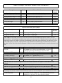
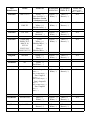
Table of Setup Codes and Values of the Parameters
Description
Code
Step Turns (Degrees per Step
Circle Time
Zig-Zag Amplitude (Degree of Turn)
Zig-Zag Period (Length)
MOB Overshoot
Clover Leaf Length
Search Spacing
6
7
8
9
14
28
25
Values of the Parameters
10 Choices/ 1.2.3.4.5.10.15.30,45,90 Degrees
10 Choices/ 1.2.3.4.5.10.15.30,45,90 Minutes
10 Choices/5 to 50 degrees by 5’s
20 Choices 1/2 to 10 minutes by 1/2’s
1 Most overshoot command. 40 most undershoot
500 to 6,000ft by 100ft increments
50 to 1,000ft by 50 ft increments
Factory
Defaults
15
5
30
1.5
10
1,000
50
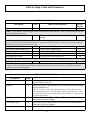
NAVIGATION FUNCTION CODES
Description
Navigation Gain
Navigation Trim Gain
Code
15
16
Values of the Parameters
1 lowest gain, 73 highest gain
1 lowest gain, 73 highest gain
Factory
Defaults
50
49
Code 15 & 16: Most GPS systems only send cross track error across the NMEA 0183 data bus with .01 mile (60
feet) resolution. Unfortunately, they display cross track error to the nearest foot. What this means is, don’t expect the
autopilot to zero the cross track error because the information it has is-that any crosstrack error less than 60 ft. (as seen
on the GPS display) is zero feet. Adjust parameter 15 up until the boat oscillates back and forth near the course line,
then back it down a few clicks. Increase parameter 16 until you can see that standoff from the course line decreases over
time.
[Up Arrow] for Mag [Down Arrow] for True Heading
MAG
In [Standby] Press and hold GPS [Select Load]- if Up Arrow
LED lights, point boat north-then press and release DM
Use Synthetic XTE
167
[Up Arrow] for on, [Down Arrow] for off
On
Code 167: On some GPS’ this code may result in tighter tracking near waypoints.
Use NMEA Checksum
347
[Up Arrow] for on, [Down Arrow] for off
On
Code 347: If your GPS calculates checksums wrong, you may still be able to use it with this code turned off. Data
integrity is compromised in this condition.
Use Reversed XTE
18
[Up Arrow] for on, [Down Arrow] for off
Off
Code 18: Some GPS’ send the wrong direction to steer with the crosstrack error signal. Use this code to fix this
problem.
Use GPS 1 GPS 2
34
[Up Arrow] for 2, [Down Arrow] for 1
1
Code 34: This code switches between the two sources of NMEA navigation data used by the autopilot to steer with.
Update rate for HDG out
49
0 (off) to 10 HZ Update Rate
10 HZ
Code 49: With this code at the bottom of its range (Down Arrow LED on) the autopilot does not transmit $APHDG. With
any settings other than off, the data is transmitted at a rate equal to (1-code 49 setting) HZ. up to a maximum rate of 10 Hz.
Fine Heading Adjust
168
[Up Arrow] increase heading out .1 deg. [Down Arrow] decreases
heading out .1 deg. Note: Very Slow response to buttons.
Use Magnetic North
Set North
17
48
33
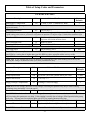
Table of Setup Codes and Parameters
FINE TUNING CODES
Description
Code
Values of the Parameters
Factory
Defaults
39
Acceleration Limiter
5
1 lowest accel, 100 Highest accel
Code 5: This parameter limits the aggressiveness of the autopilot controlled turns. Turn it up to allow higher rate turns
and down to limit the turn rate.
Seastate Filtering
1
1 least responsive steering, 4 most responsive
steering
4
Code 1: Seastate adjustments, toward least responsive, slow the heading response down and reduce rudder activity. Most of the
time you will want to run with this parameter all the way at the top of its range. In choppy or trailing seas at low speeds, reducing
this parameter will save wear and tear on your system.
Low Speed Rudder Gain
27
1 lowest gain 97 highest gain
39
Low Speed Counter Rudder Gain
37
1 lowest gain, 97 highest gain
72
High Speed Rudder Gain
29
1 lowest gain 97 highest
39
High Speed Counter Rudder Gain
39
1 lowest gain, 97 highest gain
72
Following Seas Switch
159
[Up Arrow] on, [Down Arrow] off
off
Code 159: Turning this parameter on may increase stability in severe trailing seas.
Turn Stop Adjust
268
1 least adjustment, 40 most adjustment
1
Code 268: At planing speed and for large turn angles; if your boat tends to turn further than you programmed for, (like
50 degrees when you programmed 45 degrees) and then slowly recovers to the turn angle you expected, turning this
parameter up may solve the problem.
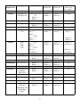
AUTOMATED SETUP CODES
Description
Calibrate Compass
Autotune
Code
47
58
Hold Down [Select Load] Button, Press and Release Deckmount Button
to Start Calibration Process
Hold Down [Select Load] Button, Press and Release Deckmount Button
to Start Tuning Process.
Code 57: Code 57 lets you select an alternate autotune. You may want to try this
if the normal tune didn’t work. After selecting the alternate by selecting code 57 and
pressing the Down Arrow button (so that the Down Arrow LED is lit), go back to code
58 to initiate the autotuner.
Load Factory Compass
247
Load Factory Pilot
248
Show Software Version
369
Hold down [Select Load] button, Press and Release Deckmount Button
to Reload Factory Pilot Settings
Hold Down [Select Load] Button, press and release Deckmount Button
to Reload Factory Pilot Settings
Hold Down [Select Load] Button, version=blink code/100
34
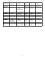
Table of Setup Codes and Parameters
TACHOMETER CODES
Description
Code
RPM Source Configuration
Values of the Parameters
259
1, none/ 2, Port/ 3, Starboard/ 4, Both
267
1 to 255 by 1’s
Factory
Defaults
2
Code 259: For single engine installations, set this code to 2 (1 blink) (and hook the blue and black wires up to your
engine tach leads).
Pulses per Revolution
6
Code 267: The number of tach pulses per engine revolution is an engine specific parameter. The following settings are
a good starting point, however you need to verify them on operation. V8 engines 4 ppr (3 blinks) Most outboards 6 ppr
Show Port RPM
35
Hold Down [Select Load] button: 1000’s blink on
Up Arrow 100’s blink on Down Arrow
Show Starboard RPM
36
Same As Above
Transition RPM
348
100 to 6000 by 100’s
3000
Code 348: Set this code to the RPM’s that your boat runs when almost on plane.
Low RPM Limit
357
100 to 6000 by 100’s
500
Code 357: If your autopilot runs well at all RPMs but is a little too active at idle, you can increase this low
limit RPM to a setting that is higher than your idle RPM to reduce autopilot rudder activity at idle.
High RPM Limit
359
100 to 6000 by 100’s
6000
Code 359: If your autopilot runs well at all RPM’s but you would like a little stiffer heading hold at the top end,
reducing this setting to an RPM lower than your actual peak RPM will help
HYDRAULIC CODES
Description
Code
Values of the Parameters
Helm Displacement
269
.1 to 6 by .1’s
Pump Displacement
169
[Up Arrow] for 4 liter, [Down Arrow] for 2 liter
Turns Lock to Lock
26
.1 to 10 by .1’s
Sloppy Linkage Compensation
257
8 settings, 8 for most sloppy
Factory
Defaults
1.7
2 liter
4.5
1
Code 257: In case of sloppy and loose steering linkages, increasing this parameter may help to reduce heading
oscillations due to the linkage. Use with caution.
Shadow Drive Desensitize
368
1 most sensitive, 40 least sensitive
20
Code 368: If the shadow drive is being false tripped, i.e., autopilot is disconnected when the helm is held
still, increasing this parameter may help. False tripping is usually due to leakage of fluid past the helm pump
lock valve. You may need to repair the helm valves if you cannot eliminate false trips.
Shadow Drive Enable
367
[Up Arrow] for On, [Down Arrow] for Off
on
Reversed Hoses
249
[Up Arrow] for Reversed, [Down Arrow] for Normal
Norm
Code 249: In case of hoses installed backwards, use this code to electronically reverse the steering direction.
35
Section V
GPS Connection Guide
This chart is a guide only and is to help you with your GPS connections and should not be used as factual
information. Please check your GPS manual for verification of NMEA 0183 connections on your application.
This is not a compatibility chart, but most all GPS’s are compatible with the TR-1 Gladiator.
GPS
Manufacturer
Model
From GPS
To Autopilot
NMEA In #1
To Autopilot
NMEA In #2
NMEA Out
Radar Overlay
Furuno
1850-D/F/DF
White ( + )
Black ( - )
Yellow ( + )
White ( - )
Blue ( + )
Brown ( - )
Yellow ( + )
Green ( - )
Furuno
1700/1700C/
1710C
White ( + )
Black ( - )
Yellow ( + )
White ( - )
Blue ( + )
Brown ( - )
N/A
Furuno
1944 C/NT
Port 2
White ( + )
Black ( - )
Yellow ( + )
White ( - )
Blue ( + )
Brown ( - )
Port 3
White ( + )
Black ( - )
Furuno
18x3 19x3
GD 1900
Data 2
White ( + )
Black ( - )
Data 3
White ( + )
Black ( - )
Yellow ( + )
White ( - )
Blue ( + )
Brown ( - )
N/A
Garmin
GPS Map 76
GPS 176
Brown ( + )
Black ( - )
Yellow ( + )
White ( - )
Blue ( + )
Brown ( - )
N/A
Garmin
GPS Map 162
Blue ( + )
Black ( - )
Yellow ( + )
White ( - )
Blue ( + )
Brown ( - )
N/A
Garmin
GPS 178C
GPS Map 182
GPS Map 182C
GPS Map 232
Com 1
Blue ( + )
Black ( - )
OR
Com 2
Green ( + )
Black ( - )
Yellow ( + )
White ( - )
Blue ( + )
Brown ( - )
N/A
Garmin
GPS Map 2006
GPS Map 2010
GPS Map 17N
Port 2 Out
Gray ( + )
Ground Black ( - )
Yellow ( + )
White ( - )
Blue ( + )
Brown ( - )
N/A
36
GPS
Manufacturer
Model
From GPS
To Autopilot
NMEA In #1
To Autopilot
NMEA In #2
Garmin
GPS Map 238
GPS Map 188
NMEA Out, Com
1 tx
Blue ( + )
Black ( - )
Yellow ( + )
White ( - )
Blue ( + )
Brown ( - )
Garmin
E-Trex
White ( + )
Black ( - )
Yellow ( + )
White ( - )
Blue ( + )
Brown ( - )
Garmin
3010
3210
Com 1
Blue ( + )
Black ( - )
Com 2
Gray ( + )
Black ( - )
Port 1
Gray ( + )
Pink ( - )
Port 2
Blue ( + )
Blue/White ( - )
Yellow ( + )
White ( - )
Blue ( + )
Brown ( - )
Brown ( + )
Black ( - )
Blue ( + )
Brown ( - )
Violet ( + )
Black ( - )
White ( + )
Orange/White ( - )
Garmin
4208
4212
5208
5212
Yellow ( + )
White ( - )
NMEA Out
Radar Overlay
Red ( + ) Black ( - )
N/A
Brown ( + )
Brown/White ( - )
Hummingbird
NS25
Red ( + )
Black ( - )
Yellow ( + )
White ( - )
Blue ( + )
Brown ( - )
N/A
Hummingbird
981, 987, 987C
White ( + )
Black ( - )
Yellow ( + )
White ( - )
Blue ( + )
Brown ( - )
N/A
Lowrance
Global Map 1600
LMS 160
LMS 350A
White ( + )
Black ( - )
Yellow ( + )
White ( - )
Blue ( + )
Brown ( - )
N/A
Lowrance
Global Map 2000
Green ( + )
Black ( - )
Yellow ( + )
White ( - )
Blue ( + )
Brown ( - )
N/A
Lowrance
LMS 240
LMS 480
Global Map 3200
Global Map
3300C
Yellow ( + )
Shield ( - )
Yellow ( + )
White ( - )
Blue ( + )
Brown ( - )
N/A
37
GPS
Manufacturer
Model
From GPS
To Autopilot
NMEA In #1
To Autopilot
NMEA In #2
NMEA Out
Lowrance
LMS 332/337
Yellow ( + )
Bare Grnd Wire ( - )
Must have Version
1.2 Software to work
Yellow ( + )
White ( - )
Blue ( + )
Brown ( - )
N/A
Lowrance
LMS 320
LMS 325
Com 1
Yellow ( + )
Shielded wire ( - )
Yellow ( + )
White ( - )
Blue ( + )
Brown ( - )
N/A
Lowrance
LCX 104C
Blue ( + )
Shielded ( - )
Yellow ( + )
White ( - )
Blue ( + )
Brown ( - )
N/A
Lowrance
Global Map
5000LCX 15,
MtLCX 16,
LCX 18
CILCX 19-C
LMS 330C/335
Com 1
Yellow ( + )
Shielded Wire ( - )
Com 2
Blue ( + )
Shielded Wire ( - )
Yellow ( + )
White ( - )
Blue ( + )
Brown ( - )
N/A
Magellan
Meridian
Orange ( + )
Black ( - )
Yellow ( + )
White ( - )
Blue ( + )
Brown ( - )
N/A
NorthStar
952
NorthStar
6000i
Yellow ( + )
White ( - )
Blue ( + )
Brown ( - )
N/A
Blue ( + )
White ( - )
Yellow ( + )
White ( - )
Blue ( + )
Brown ( - )
N/A
Yellow ( + )
Brown ( - )
Yellow ( + )
White ( - )
Blue ( + )
Brown ( - )
N/A
Radar Overlay
Red ( + ) Black ( - )
Violet ( + )
Blue/White ( - )
Port 1 Output A
Violet ( + )
Blue w/white Stripe ( - )
Port 1 Input A
Brown ( + )
White w/blue Stripe ( - )
Port 1 Output B
Gray ( + )
Blue w/white stripe ( - )
Port 1 Input B
Blue ( + )
White ( - )
RayMarine
RayMarine
SL70RC Plus
Raychart 425
38
RayMarine
GPS
Manufacturer
RayMarine
C Series
E Series
Model
Yellow ( + )
Brown ( - )
From GPS
L1260DRC
Blue ( + )
Shield Grnd ( - )
Off NMEA Heading
Page 4-9 of Manual
Simrad
GN 33
Simrad
CP40,
All CA Models,
CR 40/42/50/52
CE 32
Yellow ( + )
White ( - )
To Autopilot
NMEA In #1
Yellow ( + )
White ( - )
Blue ( + )
Brown ( - )
To Autopilot
NMEA In #2
Blue ( + )
Brown ( - )
White ( + )
Green ( - )
NMEA Out
Radar Overlay
N/A
White ( + )
Shielded wire ( - )
Yellow ( + )
White ( - )
Blue ( + )
Brown ( - )
N/A
White ( + )
Brown ( - )
Yellow ( + )
White ( - )
Blue ( + )
Brown ( - )
N/A
White ( + ) (TXA)
Brown ( - ) (TXB)
Yellow ( + )
White ( - )
Blue ( + )
Brown ( - )
N/A
39
Chapter II
................
Installation of Wireless Remote
Optional Accessory
Five Button
Two Button
This chapter will provide detailed information to accurately and successfully install the
TR-1 Gladiator Wireless Remote Unit.
Section I: Parts List
Section II: Introduction
Remote Functions
Section III: Installation
Installation Considerations
Installation
Installation Diagram
Section IV:
Security Codes
Replacement Keypad
Changing Batteries
40
Section I
Parts List Wireless Two Button
Item
Description
Part #
Qty.
1
2
3
120-2420-02
4
9
8
7
Wireless keypad transmitter
Neck Lanyard
Antenna
Antenna Base
#4-40 x 3/8 Php Screw
Receiver/cable assembly
#4-40 x 1 Oval head Screw
#4 x 1 Php Sheet Metal Screw
#4-40 x 1 Php Screw
2
1
1
1
1
1
2
2
2
6
10
#4 x 1 Oval Head Sheet Metal Screw
#4-40 Nut
310-0172-16
41
305-2401-00
240-2452-00
340-2451-00
310-0072-03
130-2410-00
310-0104-16
310-0072-13
310-0004-16
310-0041-02
2
4
Parts List Wireless Five Button
Item
Description
Part #
Qty.
1
2
3
120-2420-00
4
9
8
7
Wireless keypad transmitter
Neck Lanyard
Antenna
Antenna Base
#4-40 x 3/8 Php Screw
Receiver/cable assembly
#4-40 x 1 Oval head Screw
#4 x 1 Php Sheet Metal Screw
#4-40 x 1 Php Screw
2
1
1
1
1
1
2
2
2
6
10
#4 x 1 Oval Head Sheet Metal Screw
#4-40 Nut
310-0172-16
42
305-2401-00
240-2452-00
340-2451-00
310-0072-03
130-2410-00
310-0104-16
310-0072-13
310-0004-16
310-0041-02
2
4
Section II
Introduction
Thank You
Thank You for the purchase of your TR-1 Gladiator wireless remote. TR-1 wireless remote has been
designed to give fishermen that competitive edge in fishing and unparalleled precision and control of
their boat. TR-1 Autopilots is dedicated to create the finest controls and guidance systems for the best in
boating and fishing.
Safety
You are responsible for the safe and prudent operation of your vessel. Your TR-1 Gladiator autopilot
and wireless remote is a tool that will enhance your capability to operate your boat. It does not relieve
you from the responsibility for safe operation of your vessel. You must avoid hazards to navigation and
never leave the helm unattended.
You must always be prepared to promptly regain manual control of your boat. The autopilot steering
can fail and hard over.
Learn to operate your autopilot on calm and hazard free waters.
Simultaneous operation of several radio-controlled autopilots in near proximity may cause the
autopilot to fail to respond to keypad button presses. The near boat transmitter may jam your
boat’s receiver but will not control your autopilot or render the wired remote useless.
The Wireless remote will not respond as quickly to multiple button presses as the wired remote.
There is a remote possibility that talking on a cellphone may interfere with, and possibly jam the radio
receiver. Please use caution.
Note:
The wireless remote keypad is not waterproof. Do not expose the remote to rain or water
spray. Water in the remote will cause it to malfunction. In the event the remote does get
wet, remove the battery from the remote immediately. If the remote is subject to salt-water
incursion, remove the battery and gently rinse the disassembled unit with clean isopropyl
alcohol and let it dry out before re-assembly and reuse.
43
Wireless Remote Functions, Two Button
Thank you for purchasing this accessory for your TR-1 Autopilot. Please read and understand this manual before
installing and operating this system.
The TR-1 wireless remote control is an add on system that provides the two most often used functions of the
standard TR-1 wired remote in a compact wireless form. (Note: The wireless does not replace your existing
handheld. You will still need your wired handheld to tune your autopilot or use the other functions of the
autopilot.)
Keypad push-button functions
The buttons on the wireless keypad correspond to buttons on the wired remote as indicated in the pictures
below.
Left Straight
Arrow
(Turn Button)
Right Straight
Arrow
(Turn Button)
Left Straight
Arrow
(Turn Button)
Right Straight
Arrow
(Turn Button)
44
Wireless Remote Functions, Five Button
The Five Button wireless remote control is an add on system that provides the five most often used functions
of the standard TR-1 Wired Remote in a compact wireless form.
Note: The wireless remote does not replace your existing handheld. You will need your wired handheld
to tune your autopilot or use the other special functions of the autopilot.
Keypad push-button functions
The buttons on the wireless keypad correspond to the buttons on the wired remote as indicated in the pictures
below. The center button on the wireless is programmed for whichever the wired remote is programmed to
function as, (MOB, Zig-Zags, OR Rudder).
Resume Heading
Right Straight Arrow
(Turn Button)
Left Straight Arrow
(Turn Button)
MOB
Zig-Zag
or Rudder
Save Heading
Left Straight Arrow
(Turn Button)
Right Straight Arrow
(Turn Button)
Resume Heading
MOB
Zig-Zag
or Rudder
45
Save Heading
Section III
Installation Considerations
When installing the wireless remote system: 1) Mount the receiver box and antenna away from sources of
electronic interference such as the autopilot hydraulic pump and the engines ignition systems.
Wireless Installation
1. Mount the receiver box. Use the screws provided, or use wire ties.
2. Mount the antenna using the screws provided.
3. Unplug the wired remote from the ECU wire #3, and plug in the wire coming from the receiver box unit.
See Fig.1
4. Plug the wired handheld into the second wire stub from the receiver. See Fig.2
Fig.1
Fig.2
Antenna Installation
Mount the antenna in free space and in a direct line of sight to where the keypad transmitter is expected to be
used. Do not mount the antenna in a corner or behind a bulkhead that may reflect or absorb the radio signal
from the remote.
Choose the locations for mounting the receiver and antenna such that the cable lengths allow for proper
connections. You may want to temporarily mount the components with tape or tie-wraps and try out system
operation before hard mounting any parts.
46
Section IV
Security Codes
Each keypad transmitter transmits its own unique identification code when a button is pressed. The receiver
computer must be programmed to recognize your transmitter. Program the receiver/transmitter pair by:
1) Turn the TR-1 Autopilot on.
2) Watch the LED on the receiver box, when it starts blinking-press any button on the wireless keypad until the
LED stops blinking.
You will need to do this (once) anytime you change keypads.
Replacement Remote Keypads
You may purchase replacement keypads from a TR-1 dealer.
Inside the back cover of your keypad is written a 3 Character code. This code is the security code that your
receiver has been trained to respond to. If you would like to keep this code, tell the sales representative at the
factory the code digits when you order your new keypad. If you do not care about the code, you will be sent
a keypad with a randomly assigned code. You can, of course, reprogram your receiver to recognize the new
keypad when you take it to your boat.
Changing Batteries
When the remote control system starts to respond erratically, the keypad remote may need battery replacement.
The wireless remote keypad is powered by a CR-2032 Button Lithium Cell Battery.
To access the battery for replacement, gently pry apart the two halves
of the keypad at the seam (fingernails will do for this) Once the unit
is open, remove the battery by sliding the battery out from beneath
the retainer. Replace with the same type of battery.
Caution:
The wireless remote keypad is not waterproof. Do not expose
the remote to rain or water spray. Water in the remote will
cause it to malfunction. In the event the remote does get
wet, remove the battery from the remote immediately. If the
remote is subject to salt-water incursion, remove the battery
and gently rinse the disassembled unit with clean alcohol
and let it dry out before re-assembly and reuse.
47
Battery
Limited Warranty
This TR-1 product is warranted to be free from defects in materials or workmanship for one year from the
date of purchase. Within this period, TR-1 will, at its sole option, repair or replace any components that fail in
normal use. Such repairs or replacement will be made at no charge to the customer for parts or labor, provided
that the customer shall be responsible for any transportation cost. This warranty does not cover failures due to
abuse, misuse, accident, or unauthorized alteration or repairs.
THE WARRANTIES AND REMEDIES CONTAINED HEREIN ARE EXCLUSIVE AND IN LIEU OF
ALL OTHER WARRANTIES EXPRESS, IMPLIED, OR STATUTORY, INCLUDING ANY LIABILITY
ARISING UNDER ANY WARRANTY OF MERCHANTABILITY OR FITNESS FOR A PARTICULAR
PURPOSE, STATUTORY OR OTHERWISE. THIS WARRANTY GIVES YOU SPECIFIC LEGAL
RIGHTS, WHICH MAY VARY FROM STATE TO STATE.
IN NO EVENT SHALL TR-1 BE LIABLE FOR ANY INCIDENTAL, SPECIAL, INDIRECT, OR
CONSEQUENTIAL DAMAGES, WHETHER RESULTING FROM THE USE, MISUSE, OR INABILITY
TO USE THIS PRODUCT OR FROM DEFECTS IN THE PRODUCT. SOME STATES DO NOT
ALLOW THE EXCLUSION OF INCIDENTAL OR CONSEQUENTIAL DAMAGES, SO THE ABOVE
LIMITATIONS MAY NOT APPLY TO YOU.
TR-1 retains the exclusive right to repair or replace the unit or offer a full refund of the purchase price at its
sole discretion. SUCH REMEDY SHALL BE YOUR SOLE AND EXCLUSIVE REMEDY FOR ANY
BREACH OF WARRANTY.
Online Auction Purchases: Products sold through online auctions are not eligible for rebates or other special
offers from TR-1. Online auction confirmations are not accepted for warranty verification. To obtain warranty
service, an original or copy of the sales receipt from the original retailer is required. TR-1 will not replace
missing components from any package purchased through an online auction.
International Purchases: A separate warranty is provided by international distributors for units purchased
outside the United States. This warranty is provided by the local in-country distributor and this distributor
provides local service for your unit. Units purchased outside the United States or Canada must be returned to
a TR-1 authorized dealer in the United States for service.
To obtain warranty support, call or email TR-1 Technical Support Specialists to describe the problem you are
experiencing and request a Return Material Authorization (RMA) tracking number. You will need to provide
the unit’s serial number (if applicable), your return shipping address, and a daytime telephone number.
Phone:
e-mail:
1-866-559-0229
[email protected]
After you receive the RMA number, securely package the unit and ship it (insured) to the following address:
Garmin International, Inc.
1200 E. 151st Street
RMA number (insert your RMA number here)
Dock Door #1
Olathe, KS 66062
48