1
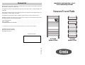
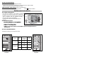
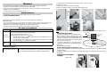
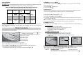
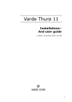
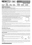
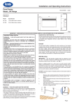
 Contact Details Please note that some of the contact details on this PDF document may not be current. Please use the following details if you need to contact us: Telephone: 0844 879 3588 Email: [email protected] The Help Centre section of this website also features a wide range of information which may be of use to you and is available 24 hours a day. It includes: • Operating and installation instructions downloads • Request a repair • Where to buy our products • Literature downloads • Heating requirement calculator www.credaheating.co.uk/help‐centre A division of GDC Group Ltd
Millbrook House Grange Drive Hedge End Southampton SO30 2DF
www.credaheating.co.uk
Registered No: 1313016 England
VAT GB 287 1315 50004
EEE Producer Registration Number –
WEE/GE0057TS
Paper from sustainable sources
GUARANTEE
We guarantee that should this heater prove to be defective by reason of faulty workmanship or material
within 24 months of the date of purchase or commencement of hire purchase we will replace the defective
parts FREE OF CHARGE on condition that:
The appliance has been correctly installed and used only on the supply circuit or voltage stamped on the
rating plate.
The appliance has been used in accordance with these instructions and has not been tampered with or otherwise subject to misuse, neglect or accident.
Installation and operating manual
To be retained by the user
NeweraTowel Rails
The appliance has not been taken apart, modified or repaired except by a person authorised by us.
EVIDENCE of the date of purchase in the form of an invoice, receipt (or hire purchase document) is included with the Appliance if returned under guarantee.
TYPE OF APPLIANCE*:
....................................................
SERIAL NUMBER*:
....................................................
CUSTOMER’S NAME AND ADDRESS: . . . . . . . . . . . . . . . . . . . . . . . . . . . . . . . . . . . . . . . . . . . . . . . . . .
....................................................
* This information can be found on the information plate situated on the left-hand side of the appliance.
Applied Energy Products Limited
Morley Way, Peterborough PE2 9JJ
www.applied-energy.com
INSTALLER’S STAMP
17-80-0019-B 1328
OUTLINE
(Model: OTRW)
SKYLINE
(Model: STRW)
Model fitted with a f an
A few recommendations:
Read the instructions before installing the device.
Isolate from the mains before working on it, and check the power supply voltage.
Store the instructions, even after installing the device.
A n t i d u s t
f i l t e r
Characteristics of the device:(shown on the rating label)
IP24: Device protected against water projections.
Class II
INSTALLING THE
The fan is fitted with an antidust filter which, when
clogged, can result in its stoppage (red indicator lit
on the device).
For better use, clean your filter regularly, according
to the following instructions.
: Double insulation.
DEVICE
1) Location of the device
Zone
3
Locate the device beyond minimum distances from .
obstacles
1. Power off the device.
60 cm
Zone
2
60 cm
Do not install the device:
ªIn
ªIn aa dra
draugh
ughtt likely
likely to
to upset
upset its
its regulation
regulation
2,25 m
- This device was designed to be installed in residential
premises. In any other case, please call your distributor.
- Installation must be ensured according to the wiring rules
and in compliance with the standards currently
enforced in the country of installation.
Red indicator
2. Extract the filter from the back of the machine.
3m
Zone
1
Control
unit
ON/OFF switch
60
cm
ªUnder a fixed mains outlet.
ªInside zone 1 in bathrooms.
ªInside zone 2 if the controls are accessible to persons using the shower or
the bath tub.
2) How to install the device
3. Clean the filter.
4. Refit the filter.
1) Position according to the diagrams below:
15 cm min
15 cm min
Version
Power
(W)
Height with
control box
(mm)
Width
(mm)
500W
656
400
Part to clean
OUTLINE
15 cm min
750W
1066
400
600W
984
470
750W
1035
470
15 cm min
5.Wait 10 minutes before restarting the device.
SKYLINE
20 cm min
Outline
These instructions are shown on the fan in the following form:
20 cm min
Skyline
4) Programming
3) Standby ( Anti-Frost ) Mode
With a pilot wire:
The appliance can be controlled remotely if its pilot wire is connected to an appliance fitted with
a programmer, ,to a central programming unit or to an energy control system.
This is the mode to maintain a temperature of approximately 7°C in the room in case of prolonged
Chart indicating the orders the device can receive over its pilot wire
(to be measured between the pilot wire and the neutral).
Orders received
No signal
Negative
half-wave
Full wave
230V
Positive
half-wave
Ref/neutral
oscilloscope
Mode achieved
COMFORT
ECO
STANDBY
STOP
Heating
temperature
COMFORT
setting
3°C to 4°C
below
COMFORT
setting
Standby
temperature,
about 7°C
Instant device
stop.
With a separate programmer:
The appliance can also be programmed independently by inserting a programmer in the housing at the rear
of the control box.This programmer will create the ECO and COMFORT modes just as you have set them
on the programmer.
USING THE
DEVICE
1) Description of the control panel
n Temperature setting knob with Anti-Frost
o
p
q
r
s
t
position
and ability to restrict the range.
Time adjustment knob TURBO 1/4h, 1/2h, 1h, 2h.
Power On indicator
TURBO indicator
TURBO control
ON/OFF switch
Heating indicator
absence from the house.
a) Leave switch s in the ON position.
.
b) Set the knob n to
4) Turbo mode This is the mode to set the device into Forced Operation, ensuring prompt temperature increase
in the room over the time defined (maximum power for conventional models)
a) Leave the switch s in the ON position.
b) Select the time for the Turbo using the knob o.
c) Press the command r, the indicator q lights.
d) The TURBO mode can be interrupted manually before the end of the time set. In order to do this,
press the command r again.
NB: On a piloted or independently programmed appliance, only the Stop and Anti-frost instructions have
priority when the TURBO mode is activated (the other instructions are ineffective).
5) Locking instructions
It is possible to lock the knob
n or restrict its use, preventing
unintentional or limited operation of
1- Locking the knob:
a) Set the knob to the position required.
b) Using a small-size flat-blade screwdriver, pull the knob’s cap (1).
c) Detach pin P from its stand using a cutting tool.
d) Set pin P in the alignment of arrow B (2).
e) Refit the cap.
2- Limitation of the knob’s use range:
a) Using a small-size flat-blade screwdriver, pull the knob’s cap (1).
b) Remove the two P pins from their stand using a cutting tool.
c) Position the two P pins at each end of the operating range desired (3).
d) Refit the cap.
1
2
3
P
P
B
2) Setting the COMFORT temperature
This is the temperature desired when the room is occupied.
a) Set the switch s to the ON position, and the p indicator lights.
b) Set knob n, the indicator t lights when the ambient temperature is below that desired.
c) Wait a few hours for the temperature to stabilise.
If the temperature setting does not suit you, adjust it using the adjusting knob n.
RECOMMENDATIONS
OF USE
- When ventilating the room, stop the device by setting the switch s to the OFF position.
- If you leave for several hours, lower the temperature.
Leaving for:
Less than 24 hours
:do not touch the controls.
More than 24 hours or during summer :set the temperature knob to
.
- Prevent children from climbing on the device. Do not insert objects or paper in the device.
- Any work on the electrical parts must be performed by skilled staff.
- During first warming, a slight smell may be evident , due to the evacuation of compounds used
during the device’s manufacturing.
- The casing may be hot, even when the device is off.
2) Carefully mark the drilling points with a pencil (draw a cross, 4cm wide).
3) Drill the four holes.
4) Position the four hooks and screw them tight.
5) Attach the appliance and 6) lock it in place with the grub screw.
MAINTENANCE
IN CASE
5
6
4
3
5
SKYLINE
- To maintain the performance of the device, about twice per year, clear the dust.
Do not use abrasive products.
- For models with a fan, use a vacuum cleaner to clear the air inlet and outlet grids, as well as the filter
(refer to the Filter paragraph).
- Every five years, have the machine’s interior checked and cleaned by a professional.
Model Outline Only
- Y ou are recommended to have the appliance and the amount of fluid checked by a professional technician
after 6 years of use and replace it if necessary. The amounts of fluid to be introduced into the
appliances are: for 500W models 3.8 litres and for 750W models 5,9 litres.
- Any deteriorated fluid must be disposed of at a waste oil collection station.
4
2
OUTLINE
WARNING
OF PROBLEM
Problem
Check
- Check that the premises circuit breakers are ON or that the shedder (if you have
one) has not interrupted the device’s power supply.
- Check the air temperature in the room.
The device
- Switch the device off, then back on (s switch):
does not heat
) If the t indicator blinks 3 times: the measurement probe is damaged. Call your electrician to ensure its replacement.
) If the t indicator blinks 5 times: power surge in device supply. Power off the device
(fuse, circuit breaker…), and call your electrician.
The heating
Check that the device is not located in a draught or that the temperature setting has not
device
heats constantly been altered.
Model with programmer only
The appliance does not follow Ensure that you use the programming unit correctly (refer to the instructhe programming instructions. tions manual), that the programmer is correctly fitted in its housing and
that it is operating normally (check the condition of the batteries).
Model with a fan only
The fan stops - Check that the air inlet grilles are not blocked. Proceed to clean them if necessary.
prematurely - Check that the room temperature has not reached too high a level. In this case, fan
stoppage is normal. Just wait for the ambient temperature to drop before reusing
the Turbo mode.
- If you live at an altitude of more than 1000m, because the air is less dense this may cause
the item to rise in temperature more quickly.This may therefore become a repetitive
problem (without having any major effect on the service life of the machine’s components).In all cases, follow the procedure below to restart the machine:
)Wait at least 10 minutes
) Switch off the appliance (switch s).
) Restart the appliance (switch s).
Note: The screws supplied are of a standard type. .In case of particular fixing needs, use appropriate screws.
.
3) Connecting the device
- The device must be supplied with 230-240V, 50Hz.
- Mains connection must be ensured using a 3-wire
cable (Brown= Live, Blue=Neutral, Black=Pilot wire),
through a connecting box. In damp premises, such as
bathrooms and kitchens, install the connecting box at
least 25cm from the ground.
- A means for disconnection in all poles must be
provided in the fixed wiring in accordance with the
wiring rules.
Panel heater cable
Live=brown
LIVE
Neutral=blue
NEUTRAL
Electricity
grid
Pilot wire=Black
Two possible cases
1st case: only one heater
2nd case: multiple heaters
The pilot wire end is insulated
and not further connected
The pilot wire of all heaters in a
control group, up to a maximum
of 20 units with any one them used
as the Master, are connected
2
by a 1.0mm 220-240V insulated cable
- Do not connect to Earth.
Do not connect the pilot wire (black) to Earth.
- If power cable is damaged or too short, to avoid any danger it must be replaced by a qualified electrician
using special tools.
- If a device is protected by a 30mA RCD (e.g. bathroom), the pilot wire supply must also be protected
by this RCD .
4) Fitting and removing the
brackets
Skyline Only
4) Programming
3) Standby ( Anti-Frost ) Mode
With a pilot wire:
The appliance can be controlled remotely if its pilot wire is connected to an appliance fitted with
a programmer, ,to a central programming unit or to an energy control system.
This is the mode to maintain a temperature of approximately 7°C in the room in case of prolonged
Chart indicating the orders the device can receive over its pilot wire
(to be measured between the pilot wire and the neutral).
Orders received
No signal
Negative
half-wave
Full wave
230V
Positive
half-wave
Ref/neutral
oscilloscope
Mode achieved
COMFORT
ECO
STANDBY
STOP
Heating
temperature
COMFORT
setting
3°C to 4°C
below
COMFORT
setting
Standby
temperature,
about 7°C
Instant device
stop.
With a separate programmer:
The appliance can also be programmed independently by inserting a programmer in the housing at the rear
of the control box.This programmer will create the ECO and COMFORT modes just as you have set them
on the programmer.
USING THE
DEVICE
1) Description of the control panel
n Temperature setting knob with Anti-Frost
o
p
q
r
s
t
position
and ability to restrict the range.
Time adjustment knob TURBO 1/4h, 1/2h, 1h, 2h.
Power On indicator
TURBO indicator
TURBO control
ON/OFF switch
Heating indicator
absence from the house.
a) Leave switch s in the ON position.
.
b) Set the knob n to
4) Turbo mode This is the mode to set the device into Forced Operation, ensuring prompt temperature increase
in the room over the time defined (maximum power for conventional models)
a) Leave the switch s in the ON position.
b) Select the time for the Turbo using the knob o.
c) Press the command r, the indicator q lights.
d) The TURBO mode can be interrupted manually before the end of the time set. In order to do this,
press the command r again.
NB: On a piloted or independently programmed appliance, only the Stop and Anti-frost instructions have
priority when the TURBO mode is activated (the other instructions are ineffective).
5) Locking instructions
It is possible to lock the knob
n or restrict its use, preventing
unintentional or limited operation of
1- Locking the knob:
a) Set the knob to the position required.
b) Using a small-size flat-blade screwdriver, pull the knob’s cap (1).
c) Detach pin P from its stand using a cutting tool.
d) Set pin P in the alignment of arrow B (2).
e) Refit the cap.
2- Limitation of the knob’s use range:
a) Using a small-size flat-blade screwdriver, pull the knob’s cap (1).
b) Remove the two P pins from their stand using a cutting tool.
c) Position the two P pins at each end of the operating range desired (3).
d) Refit the cap.
1
2
3
P
P
B
2) Setting the COMFORT temperature
This is the temperature desired when the room is occupied.
a) Set the switch s to the ON position, and the p indicator lights.
b) Set knob n, the indicator t lights when the ambient temperature is below that desired.
c) Wait a few hours for the temperature to stabilise.
If the temperature setting does not suit you, adjust it using the adjusting knob n.
RECOMMENDATIONS
OF USE
- When ventilating the room, stop the device by setting the switch s to the OFF position.
- If you leave for several hours, lower the temperature.
Leaving for:
Less than 24 hours
:do not touch the controls.
More than 24 hours or during summer :set the temperature knob to
.
Model fitted with a f an
A few recommendations:
Read the instructions before installing the device.
Isolate from the mains before working on it, and check the power supply voltage.
Store the instructions, even after installing the device.
A n t i d u s t
f i l t e r
Characteristics of the device:(shown on the rating label)
IP24: Device protected against water projections.
Class II
INSTALLING THE
The fan is fitted with an antidust filter which, when
clogged, can result in its stoppage (red indicator lit
on the device).
For better use, clean your filter regularly, according
to the following instructions.
: Double insulation.
DEVICE
1) Location of the device
Zone
3
Locate the device beyond minimum distances from .
obstacles
1. Power off the device.
60 cm
Zone
2
60 cm
Do not install the device:
ªIn
ªIn aa dra
draugh
ughtt likely
likely to
to upset
upset its
its regulation
regulation
2,25 m
- This device was designed to be installed in residential
premises. In any other case, please call your distributor.
- Installation must be ensured according to the wiring rules
and in compliance with the standards currently
enforced in the country of installation.
Red indicator
2. Extract the filter from the back of the machine.
3m
Zone
1
Control
unit
ON/OFF switch
60
cm
ªUnder a fixed mains outlet.
ªInside zone 1 in bathrooms.
ªInside zone 2 if the controls are accessible to persons using the shower or
the bath tub.
2) How to install the device
3. Clean the filter.
4. Refit the filter.
1) Position according to the diagrams below:
15 cm min
15 cm min
Version
Power
(W)
Height with
control box
(mm)
Width
(mm)
500W
656
400
Part to clean
OUTLINE
15 cm min
750W
1066
400
600W
984
470
750W
1035
470
15 cm min
5.Wait 10 minutes before restarting the device.
SKYLINE
20 cm min
Outline
These instructions are shown on the fan in the following form:
20 cm min
Skyline
GUARANTEE
We guarantee that should this heater prove to be defective by reason of faulty workmanship or material
within 24 months of the date of purchase or commencement of hire purchase we will replace the defective
parts FREE OF CHARGE on condition that:
The appliance has been correctly installed and used only on the supply circuit or voltage stamped on the
rating plate.
The appliance has been used in accordance with these instructions and has not been tampered with or otherwise subject to misuse, neglect or accident.
Installation and operating manual
To be retained by the user
NeweraTowel Rails
The appliance has not been taken apart, modified or repaired except by a person authorised by us.
EVIDENCE of the date of purchase in the form of an invoice, receipt (or hire purchase document) is included with the Appliance if returned under guarantee.
TYPE OF APPLIANCE*:
....................................................
SERIAL NUMBER*:
....................................................
CUSTOMER’S NAME AND ADDRESS: . . . . . . . . . . . . . . . . . . . . . . . . . . . . . . . . . . . . . . . . . . . . . . . . . .
....................................................
* This information can be found on the information plate situated on the left-hand side of the appliance.
Applied Energy Products Limited
Morley Way, Peterborough PE2 9JJ
www.applied-energy.com
INSTALLER’S STAMP
17-80-0019-B 1328
OUTLINE
(Model: OTRW)
SKYLINE
(Model: STRW)