1
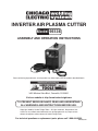
Inverter Air Plasma Cutter
Model 95136
Assembly And Operation Instructions
Due to continuing improvements, actual product may differ slightly from the product described herein.
®
3491 Mission Oaks Blvd., Camarillo, CA 93011
Visit our website at: http://www.harborfreight.com
To prevent serious injury, read and understand
all warnings and instructions before use.
Copyright© 2006 by Harbor Freight Tools®. All rights reserved. No portion of this
manual or any artwork contained herein may be reproduced in any shape or form
without the express written consent of Harbor Freight Tools.
For technical questions or replacement parts, please call 1-800-444-3353.
REV 06l, 07k
Specifications
Rated Input Voltage 230 V~ @ 50 / 60 Hz
Rated Input Current
Cutting Current
Rated Duty Cycle
15 - 40 Amps
Cutting Thickness ½” mild steel Maximum
Air Requirement
Arc Striking System Pilot Arc
Power Switch
Unit Size
20” L x 8-1/8” W x 14-3/8” H Weight
19.2 Amps
60% @ 40 A; 80% @ 34.6 A;
100% @ 31 A
60-80 PSI @ 3.5 CFM
Rocker Type
49.6 lb.
Duty Cycle
Duty Cycle is the equipment specification which defines the number of minutes
within a 10 minute period that a piece of equipment can safely operate.
This plasma cutter has a 60% duty cycle at 40 Amps, which means that it may
be used only 6 minutes at 40 Amps out of any 10 minute period, and must be rested
the remaining 4 minutes.
CAUTION: Failure to observe the duty cycle limitations of this Plasma Cutter can easily
damage this equipment, and will void the warranty.
Save This Manual
You will need the manual for the safety warnings and precautions, assembly instructions, operating and maintenance procedures, parts list and diagram. Keep your invoice
with this manual. Write the invoice number on the inside of the front cover. Keep the
manual and invoice in a safe and dry place for future reference.
Safety Warnings and Precautions
WARNING: When using tool, basic safety precautions should always be followed to reduce
the risk of personal injury and damage to equipment.
Read all instructions before using this tool!
WARNING!
READ AND UNDERSTAND ALL INSTRUCTIONS
Failure to follow all instructions listed below may result in
electric shock, fire, and/or serious injury.
SAVE THESE INSTRUCTIONS
Work Area Precautions
1.
Keep your work area clean and well lit. Cluttered benches and dark areas invite
accidents.
SKU 95136
For technical questions, please call 1-800-444-3353
Page 2.
Do not operate power tools in explosive atmospheres, such as in the presence of flammable liquids, gases, or dust. Power tools create sparks which may
ignite the dust or fumes.
3.
Keep bystanders, children, and visitors away while operating a power tool.
Distractions can cause you to lose control. Protect others in the work area from
debris such as chips and sparks. Provide barriers or shields as needed.
Electrical Safety
1.
Grounded tools must be plugged into an outlet properly installed and grounded
in accordance with all codes and ordinances. Never remove the grounding
prong or modify the plug in any way. Do not use any adapter plugs. Check
with a qualified electrician if you are in doubt whether the outlet is properly
grounded. If the tool should electrically malfunction or break down, grounding
provides a low resistance path to carry electricity away from the user.
2.
Double insulated tools are equipped with a polarized plug (one blade is wider
than the other). This plug will fit in a polarized outlet only one way. If the plug
does not fit fully in the outlet, reverse the plug. If it still does not fit, contact
a qualified electrician to install a polarized outlet. Do not change the plug in
any way. Double insulation eliminates the need for the three wire grounded power
cord and grounded power supply system.
3.
Avoid body contact with grounded surfaces such as pipes, radiators, ranges,
and refrigerators. There is an increased risk of electric shock if your body is
grounded.
4.
Do not expose power tools to rain or wet conditions. Water entering a power
tool will increase the risk of electric shock.
5.
Do not abuse the Power Cord. Never use the Power Cord to carry the tool or
pull the Plug from an outlet. Keep the Power Cord away from heat, oil, sharp
edges, or moving parts. Replace damaged Power Cords immediately. Damaged
Power Cords increase the risk of electric shock.
6.
When operating a power tool outside, use an outdoor extension cord marked
“W-A” or “W”. These extension cords are rated for outdoor use, and reduce the
risk of electric shock.
Personal Safety
1.
Stay alert. Watch what you are doing, and use common sense when operating a power tool. Do not use a power tool while tired or under the influence
of drugs, alcohol, or medication. A moment of inattention while operating power
tools may result in serious personal injury.
SKU 95136
For technical questions, please call 1-800-444-3353
Page 2.
Dress properly. Do not wear loose clothing or jewelry. Contain long hair.
Keep your hair, clothing, and gloves away from moving parts. Loose clothes,
jewelry, or long hair can be caught in moving parts.
3.
Avoid accidental starting. Be sure the Power Switch is off before plugging in.
Carrying power tools with your finger on the Power Switch, or plugging in power
tools with the Power Switch on, invites accidents.
4.
Remove adjusting keys or wrenches before turning the power tool on. A
wrench or a key that is left attached to a rotating part of the power tool may result
in personal injury.
5.
Do not overreach. Keep proper footing and balance at all times. Proper footing
and balance enables better control of the power tool in unexpected situations.
6.
Use safety equipment. Always wear eye protection. Dust mask, non-skid safety
shoes, hard hat, or hearing protection must be used for appropriate conditions.
Tool Use and Care
1.
Use clamps (not included) or other practical ways to secure and support the
workpiece to a stable platform. Holding the work piece by hand or against your
body is unstable and may lead to loss of control.
2.
Do not force the tool. Use the correct tool for your application. The correct
tool will do the job better and safer at the rate for which it is designed.
3.
Do not use the power tool if the Power Switch does not turn it on or off. Any
tool that cannot be controlled with the Power Switch is dangerous and must be
replaced.
4.
Disconnect the Power Cord Plug from the power source before making any
adjustments, changing accessories, or storing the tool. Such preventive safety
measures reduce the risk of starting the tool accidentally.
5.
Store idle tools out of reach of children and other untrained persons. Tools
are dangerous in the hands of untrained users.
6.
Maintain tools with care. Keep cutting tools maintained and clean. Properly
maintained tools are less likely to bind and are easier to control. Do not use a
damaged tool. Tag damaged tools “Do not use” until repaired.
.
Check for misalignment or binding of moving parts, breakage of parts, and any
other condition that may affect the tool’s operation. If damaged, have the tool
serviced before using. Many accidents are caused by poorly maintained tools.
8.
Use only accessories that are recommended by the manufacturer for your
model. Accessories that may be suitable for one tool may become hazardous
when used on another tool.
SKU 95136
For technical questions, please call 1-800-444-3353
Page Service
1.
Tool service must be performed only by qualified repair personnel. Service or
maintenance performed by unqualified personnel could result in a risk of injury.
2.
When servicing a tool, use only identical replacement parts. Use of unauthorized parts or failure to follow maintenance instructions may create a risk of electric
shock or injury.
Specific Safety Rules
1.
Maintain labels and nameplates on the tool. These carry important information. If unreadable or missing, contact Harbor Freight Tools for a replacement.
2.
Always wear ANSI approved safety impact eye goggles and heavy work gloves when
using the tool. Using personal safety devices reduce the risk for injury. Safety impact eye
goggles and heavy work gloves are available from Harbor Freight Tools.
3.
Maintain a safe working environment. Keep the work area well lit. Make sure there is
adequate surrounding workspace. Always keep the work area free of obstructions, grease,
oil, trash, and other debris. Do not use a power tool in areas near flammable chemicals,
dusts, and vapors. Do not use this product in a damp or wet location.
4.
Avoid unintentional starting. Make sure you are prepared to begin work before turning
on the tool.
5.
Never leave the tool unattended when it is plugged into an electrical outlet. Turn off
the tool, and unplug it from its electrical outlet before leaving.
6.
Always unplug the tool from its electrical outlet before performing and inspection,
maintenance, or cleaning procedures.
.
Prevent eye injury and burns. Wearing and using ANSI approved personal safety clothing
and safety devices reduce the risk for injury.
• Wear ANSI approved safety impact eye goggles with a welding helmet featuring at least
a number 10 shade lens rating.
• Leather leggings, fire resistant shoes or boots should be worn when using this product.
Do not wear pants with cuffs, shirts with open pockets, or any clothing that can catch and
hold molten metal or sparks.
• Keep clothing free of grease, oil, solvents, or any flammable substances. Wear dry, insulating gloves and protective clothing.
• Wear an approved head covering to protect the head and neck. Use aprons, cape, sleeves,
shoulder covers, and bibs designed and approved for welding and cutting procedures.
• When welding/cutting overhead or in confined spaces, wear flame resistant ear plugs or
ear muffs to keep sparks out of ears.
8.
Prevent accidental fires. Remove any combustible material from the work area.
SKU 95136
For technical questions, please call 1-800-444-3353
Page • When possible, move the work to a location well away from combustible materials. If
relocation is not possible, protect the combustibles with a cover made of fire resistant
material.
• Remove or make safe all combustible materials for a radius of 35 feet (10 meters) around
the work area. Use a fire resistant material to cover or block all open doorways, windows,
cracks, and other openings.
• Enclose the work area with portable fire resistant screens. Protect combustible walls,
ceilings, floors, etc., from sparks and heat with fire resistant covers.
• If working on a metal wall, ceiling, etc., prevent ignition of combustibles on the other side
by moving the combustibles to a safe location. If relocation of combustibles is not possible,
designate someone to serve as a fire watch, equipped with a fire extinguisher, during the
cutting process and for at least one half hour after the cutting is completed.
• Do not weld or cut on materials having a combustible coating or combustible internal structure, as in walls or ceilings, without an approved method for eliminating the hazard.
• Do not dispose of hot slag in containers holding combustible materials. Keep a fire extinguisher nearby and know how to use it.
• After welding or cutting, make a thorough examination for evidence of fire. Be aware that
easily visible smoke or flame may not be present for some time after the fire has started.
Do not weld or cut in atmospheres containing dangerously reactive or flammable gases,
vapors, liquids, and dust.
• Provide adequate ventilation in work areas to prevent accumulation of flammable gases,
vapors, and dust. Do not apply heat to a container that has held an unknown substance
or a combustible material whose contents, when heated, can produce flammable or explosive vapors. Clean and purge containers before applying heat. Vent closed containers,
including castings, before preheating, welding, or cutting.
• Only use compressed air to operate the Plasma Welder/Cutter. Never use other compressed gases. Don’t exceed maximum PSI for this product as stated on the specification
table on page 2.
Inhalation Hazard
Welding/Plasma Cutting Producestoxic fumes and gasses.
Exposure to welding or cutting gasses can increase the risk of
developing certain cancers, such as cancer of the larynx and
lung cancer. Also, some diseases that may be linked to exposure
to welding or plasma cutting gasses or fumes are:
• Early onset of Parkinson’s Disease
• Heart Disease
• Damage to the reproductive organs
• Ulcers
• Inflammation of the small intestine or stomach • Kidney damage
• Respiratory diseases such as emphysema, bronchitis or pneumonia
Safety precautions, such as using natural or forced air ventilation and
wearing an ANSI approved respirator, are essential to reduce the
risk of developing the above illnesses.
9.
Avoid overexposure to fumes and gases. Always keep your head out of the fumes. Do
not breathe the fumes. Use enough ventilation or exhaust, or both, to keep fumes and gases
from your breathing zone and general area.
SKU 95136
For technical questions, please call 1-800-444-3353
Page • Where ventilation is questionable, have a qualified technician take an air sampling to
determine the need for corrective measures. Use mechanical ventilation to improve air
quality. If engineering controls are not feasible, use an approved respirator.
• Work in a confined area only if it is well ventilated, or while wearing an air-supplied respirator.
• Follow OSHA guidelines for Permissible Exposure Limits (PEL’s) for various fumes and
gases.
• Follow the American Conference of Governmental Industrial Hygienists recommendations
for Threshold Limit Values (TLV’s) for fumes and gases.
• Have a recognized specialist in Industrial Hygiene or Environmental Services check the
operation and air quality and make recommendations for the specific welding or cutting
situation.
10.
Always keep hoses away from welding/cutting spot. Examine all hoses and cables for
cuts, burns, or worn areas before each use. If any damaged areas are found, replace the
hoses or cables immediately.
11.
Read and understand all instructions and safety precautions as outlined in the
manufacturer’s manual for the material you will weld or cut.
12.
Proper cylinder care. Secure cylinders to a cart, wall, or post, to prevent them from falling. All cylinders should be used and stored in an upright position. Never drop or strike a
cylinder. Do not use cylinders that have been dented. Cylinder caps should be used when
moving or storing cylinders. Empty cylinders should be kept in specified areas and clearly
marked “empty.”
13.
Never use oil or grease on any inlet connector, outlet connector, or cylinder
valves.
14.
Use only supplied Torch on this Inverter Air Plasma Cutter. Using components from
other systems may cause personal injury and damage components within.
15.
WARNING! This product, when used for cutting and similar applications, contains or produces a chemical known to the State of California to cause cancer and birth defects (or
other reproductive harm). (California Health & Safety Code § 25249.5, et seq.)
16.
WARNING! People with pacemakers should consult their physician(s) before using this
product. Electromagnetic fields in close proximity to a heart pacemaker could cause interference to, or failure of the pacemaker.
This product requires a 3-prong, 230 V~, polarized, twist-lock plug (not included). This plug
must be installed by a qualified electrician.
SKU 95136
For technical questions, please call 1-800-444-3353
Page Symbology
Double Insulated
Canadian Standards Association
Underwriters Laboratories, Inc.
V~
A
Volts Alternating Current
Amperes
n0 xxxx/min. No Load Revolutions per Minute (RPM)
Preparing Your Work Area
1.
You must have a sturdy work table that is open below the area you are cutting. Molten
slag will be blown through the work metal, and must be able to fall away freely.
2.
Your work table must allow the work metal to be firmly clamped to prevent it accidentally
falling or moving.
3.
The floor and surrounding area of your work site must not be flammable. A clean
cement floor is recommended. The cutting process will eject molten metal slag onto
the floor, and it will scatter for 8-10 feet or more in any direction. Have an adequate
fire extinguisher available if needed.
Unpacking
When unpacking, check to make sure the following parts are included.
Inverter Plasma Cutter tool with
Cutting Torch with Power Cord
Ground Cable with Clamp
If any parts are missing or broken, please call Harbor Freight Tools at the number on the cover
of this manual.
SKU 95136
For technical questions, please call 1-800-444-3353
Page Assembly
Attaching the Electric Plug (not supplied):
1.
Before use, a plug must be wired to the 230 V~
power cable. CAUTION: This operation must
only be done by a qualified electrician.
2.
The Green wire is ground, the Black and White
wires are both ‘HOT’ 110 V~ conductors.
3.
Use the plug appropriate to your 230 V~ service
outlet. Be sure the circuit is protected with an
appropriate circuit breaker.
Grounding the Tool:
Attach a ground wire of at least 14 Ga. thickness
(not supplied) to the screw on the lower left of the
back of the tool case. Connect the other end of
the wire to an appropriate ground, such as a steel
workbench, steel building member or grounding
electrode.
Attaching the Air Supply:
WARNING: Only use dry air as the gas in this tool. Use
of any other gas, such as oxygen, acetylene, etc. may cause explosion.
1.
A male quick release adapter is mounted on the rear of the tool. Attach your
pressurized air supply using your female quick release adapter. Adjust your
air supply to deliver 60-80 PSI at 3.5
CFM.
2.
During operation, you can regulate air
pressure through the Plasma Cutter by
adjusting the knob located on top of
the tool.
3.
If the tool becomes over pressurized,
there is a pressure relief valve on the
top of the unit.
Handle
Air pressure
regulator knob
Air pressure gauge
SKU 95136
For technical questions, please call 1-800-444-3353
Air input coupling
Page Controls and Indicators
1.
Power Switch. Up is ON, down is OFF.
2.
Digital Amps Meter. Shows actual cutting
current, which will vary during operation.
3.
1
7
Thermal Overload Indicator Lamp. This
light will come on, and the device will shut
down if the tool becomes overheated. Stop
trying to use the cutter while leaving the
power switch ON to allow the cooling fan
to operate, and the lamp will turn off automatically when the machine cools down.
Please pay attention to the Rated Duty
Cycle discussed on page 2.
4.
Power ON Light.
5.
Power Supply Controller.
6.
Mode Selector. Turns the air supply ON
prior to cutting.
Torch Connector
.
2
4
Power
WORKING
3
5
6
Ground Connector
Working Indicator Light. Will be on during cutting operation.
Operation
Note: Before beginning, please read and understand all the safety precautions starting on page 2, and especially the section “Specific Safety Rules” starting on
page 4.
1.
Mount the metal to be cut to the metal welding-cutting table. It should be mounted
so that the cutting debris falls to the cement floor.
2.
Place the Air Plasma Cutter unit no closer than six feet from the workpiece to be
cut.
3.
Connect an air hose and coupling (not supplied) from the air supply tank to the Air
Input Coupling at the rear of the unit. See photo on page 9, bottom. The air supply
must be regulated to between 60 and 80 PSI as read on the Air Pressure Gauge. The
air supply must be dry. It is recommended to install a moisture filter (not included)
on the compressor. Do not use an air oiler.
4.
Connect the Torch Cable plug into the twist-lock connector on the lower left unit
front. Twist to lock.
5.
Plug in the Grounding Cable into the Ground Connector on the lower right of the
unit front. Twist to lock.
SKU 95136
For technical questions, please call 1-800-444-3353
Page 10
6.
Securely place the clamping end of the Grounding Cable Clamp to a part of the
workpiece or metal table that is clean of paint, oil, or dirt. Clamp as close as possible to the workpiece without damaging the cable during cutting.
.
Verify that the Power Switch is in the Off (O) position, then plug the 230 V~ line cord
plug into an appropriate 230 V~ outlet.
8.
Turn the Power Supply Controller to the desired current (15 to 40 amps).
9.
Adjust air pressure by turning the Pressure Regulator Knob on top of the unit (see
photo on page 9). Read pressure on Pressure Gauge.
10.
When everything is in place for cutting, press the Power Switch UP to the ON position. The green Power On Light will illuminate, but the Torch is not yet energized.
11.
Orient yourself to one side of the area to be cut, and move the Welding Helmet Face
Shield (not included, see page 5 item 7) over your eyes.
12.
Be careful! Pilot Plasma Arc can severely injure. Once the trigger is squeezed, the arc will ignite. This unit provides a pilot arc, so the torch
does not need to contact the workpiece before the cutting arc ignites.
13.
(Refer to parts diagram below for Torch Handle components.) Direct torch away
from people and flammables while you squeeze (and hold) the Torch Handle Trigger (2A) to energize the Torch Electrode (4A). The air output is delayed a few seconds to enable a proper arc to begin.
Caution: The Torch handle is now energized. Be careful not 3A
to touch anything else with the Torch except the workpiece to be cut.
Warning: Never look at the ignited arc without ANSIapproved, arc shaded, eye protection in a full
face shield. Permanent eye damage or blind- 4A
ness can occur. Skin burns can occur. Never 5A
breathe arc fumes.
6A
14.
15.
Bring the Electrode (4A) of the Torch close 7A
to the starting point of the cut. The Working
Indicator Light will come on.
1A
2A
Part Description
1A
Handle
2A
Trigger
3A
Body
4A
Electrode
5A
Insulating Diffuser
6A Nozzle
Slowly move the Torch at a slight angle along the
7A Nozzle Holder
cutting line with the Torch tip trailing.
The air causes the molten metal to fall away from the
workpiece being cut. If proper cutting is not achieved, adjust the Power Supply
Controller to a higher level, and/ or increase air flow. To increase air flow, press the
Power Switch to the Off (O) position, then adjust the air pressure at the Air Pressure
Regulator. The air will continue to come out of the Torch Handle for a few seconds
once the trigger is released.
SKU 95136
For technical questions, please call 1-800-444-3353
Page 11
Note: If too much current is drawn from the Plasma Cutter (i.e., short circuit), the Thermal
Switch, an overload protector, will activate and the red Thermal Overload Indicator
Light will light. The Plasma Cutter will turn off until it cools down. To reset you must
turn the power OFF then back ON. Press the Trigger to begin cutting again.
16.
When finished cutting:
a. Release the Torch handle trigger and lift the Torch handle from the workpiece,
b. Press the Power Switch to the Off (O) position,
c. Set the Torch handle down on the metal workbench,
d. Turn the air supply off,
e. Unplug the line cord from the electrical outlet.
Plasma Cutting Technique
Using a plasma cutter is a skill that requires time and effort to do well. Practice
striking and maintaining an arc on scrap work pieces before beginning work. This will help
you gauge the best settings for the plasma cutter for the material at hand.
1.
You can cut any metal that will conduct electricity up to approximately ½” thick mild
steel or equivalent. Very thin or very thick metals are more difficult to cut cleanly.
2.
Generally set the air pressure between 60 and 80 psi. Increased air pressure will
increase plasma speed and cutting pressure. Air pressure and amperage should
be adjusted in tandem.
3.
Generally start with a mid-range amperage setting (32-33 amps) and adjust up or
down from there. Increased amperage will increase cutting heat. This is needed with
heavier and harder metals. However, increased amperage will reduce Duty Cycle
time. (See page 2.)
4.
Move the cutting head more slowly for thicker and harder metals, and more quickly
for thin or soft metals. Keep the cutting head moving while cutting.
SKU 95136
For technical questions, please call 1-800-444-3353
Page 12
How Plasma Cutters Work
Plasma cutters work by feeding an inert gas (air) through an electric arc. The air
is then heated to an extremely high temperature which converts the gas to plasma which
cuts the metal.
High temperature and pressure are required to create a plasma. The electric arc
provides the temperature, and by exhausting the air through a very small orifice, the pressure is increased far beyond the 60-80 PSI operating pressure of the air supply.
What is Plasma?
Materials in Nature exist in one of four different states: Solid, Liquid, Gas or Plasma.
Plasma is very rare on Earth because of its very high temperature, however most of the
matter in the universe is plasma. The Sun, stars and galaxies are made of plasma. On
Earth, you will find plasma in lightening and a few other places. Neon tubes and florescent
lights contain low-temperature plasma when lighted.
The difference between water ice, liquid water and water vapor is temperature. In
each of these states, temperature energy pushes the molecules of water away from each
other to change the state the water is in. At very high temperature and pressure the water
molecules themselves break apart, and the atoms begin to ionize. Normal atoms are made
up of protons and neutrons in the nucleus, surrounded by a cloud of electrons. In plasma,
the electrons separate from the nucleus. The electrons are negatively charged, and they
leave behind their positively charged nuclei which are known as ions. When the fast-moving
electrons collide with other electrons and ions, they release vast amounts of energy. This
energy is what gives plasma its unusual status and great cutting power.
How do Plasma Cutters Work?
Plasma cutters work by sending a pressurized gas through a small channel. In the
center of this channel, there is a negatively charged electrode. When power is supplied
to the negative electrode, and the tip of the nozzle contacts the work metal, the connection creates a circuit. When the nozzle is lifted away, the arc will continue. As the inert gas
passes through the channel, the arc heats the gas until it becomes ionized. This reaction
creates a stream of directed plasma, approximately 30,000° F (16,649° C) and moving at
approximately 20,000 feet per second (6,096 m/sec), that reduces metal to molten slag.
The plasma itself conducts electrical current. The cycle of creating the arc is continuous as long as power is supplied to the electrode and the plasma stays in contact with
the metal that is being cut. In order to ensure this contact, protect the cut from oxidation,
and regulate the unpredictable nature of plasma, the cutter nozzle has a second set of
channels. These channels release a constant flow of shielding gas around the cutting area.
The pressure of this gas flow effectively controls the radius of the plasma beam.
SKU 95136
For technical questions, please call 1-800-444-3353
Page 13
Maintenance
WARNING! Make sure the Power Switch of the Plasma Cutter is in its “OFF” position
and that the tool is unplugged from the electrical outlet before performing any
inspection, maintenance, or cleaning procedures.
1.
Before each use, inspect the general condition of the Air Plasma Cutter. Check
for loose cable connections, misalignment or binding of the fan, cracked or broken
parts, damaged electrical wiring, and any other condition that may affect its safe
operation. If abnormal noise or vibration occurs, have the problem corrected before
further use. Do not use damaged equipment.
2.
Periodically recheck all nuts, bolts, and screws for tightness.
3.
Periodically blow the dust from the cooling vents with compressed air.
4.
Verify that the cooling fan is operational before cutting.
5.
If the unit repeatedly shuts down from thermal overload, stop all use. Have the Air
Plasma Cutter inspected and repaired by a qualified service technician.
6.
Store the welder and accessories in a clean and dry location.
.
Periodically disassemble and clean the Torch Head components with steel wool.
Replace burnt, cracked, distorted, or coated components. Refer to the assembly
drawing on page 16.
8.
To gain access to the internal components of the unit, remove screws from Main
Body Cover. The home user is strongly advised not to remove the tool covers and
not to attempt any electronic repairs. Any repairs must be completed by a qualified
technician. Opening the tool will void any warranties, and may result in damage to
equipment or possible personal injury. Don’t do it.
9.
On a daily basis check for any of the following problems: if any are found, take the
tool to a qualified repair technician.
a. Abnormal vibration, sound or smell.
b. Abnormal heating at any cable connection.
c. The fan does not work properly.
d. Any switch or control does not work properly.
e. Any damage to cables.
SKU 95136
For technical questions, please call 1-800-444-3353
Page 14
Parts List
Part
Description
Q’ty
Part
Description
Q’ty
1
Handle
1
20
Torch Cable Connector
1
2
Main Body Cover
1
21
Coil
1
3
Control Circuit Board
1
22
Ground Cable Connector
1
4
Control Transformer
1
23
Lower Cover
1
5
Power Supply Circuit Board
1
24
Cement Resistor
3
6
Chassis
1
25
Drive Circuit Board
1
7
Transfer Arc Circuit Board
1
26
Inverter Circuit Board
1
8
Transformer
1
27
Air Pressure Relief Valve
1
9
Reactor
1
28
Air Pressure Gauge
1
10
Radiator
4
29
Fan
1
11
Rectifier Circuit Board
1
30
Fan Grill
1
12
Rectifier Bridge
1
31
Splitter
1
13
Metal Resistor
2
32
Air Supply Solenoid
1
14
Breaker
1
33
Insulated Foot
4
15
Working Indicator
1
34
Reactor Bracket
1
16
Mode Selector
1
35
Power Cord
1
17
Overheat Indicator
1
36
Digital Display
1
18
Power Supply Controller
1
37
Reactor
1
19
Power Indicator
1
PLEASE READ THE FOLLOWING CAREFULLY
The manufacturer and/or distributor has provided the parts list and assembly diagram in this manual as a reference tool only. Neither the manufacturer
or distributor makes any representation or warranty of any kind to the buyer
that he or she is qualified to make any repairs to the product, or that he or
she is qualified to replace any parts of the product. In fact, the manufacturer
and/or distributor expressly states that all repairs and parts replacements
should be undertaken by certified and licensed technicians, and not by the
buyer. The buyer assumes all risk and liability arising out of his or her repairs
to the original product or replacement parts thereto, or arising out of his
or her installation of replacement parts thereto.
SKU 95136
For technical questions, please call 1-800-444-3353
Page 15
Assembly Diagram
NOTE: Some parts are listed and shown for illustration purposes only and are not available individually as
replacement parts.
SKU 95136
For technical questions, please call 1-800-444-3353
Page 16
Wiring Diagram
REV 07i
SKU 95136
For technical questions, please call 1-800-444-3353
Page 17
Troubleshooting
Important!
Be CERTAIN to shut off the Plasma Cutter, and disconnect it from power and air before
adjusting, cleaning, or repairing the unit. A technician should discharge all capacitors before
performing any internal procedures.
Fan Runs when switched on but Arc will not ignite
The Air pressure may be too high or too
low. Check the Air Pressure setting on
the regulator’s gauge.
Air Pressure
Too high
Air Pressure
correct
Adjust the Air Regulator
to deliver only 60-80 PSI
to the Cutter.
Make sure that all air and
electrical connections are
tight.
Loose
Connections
Shut off switch, if not off already, and
tighten connections.
If connections do not tighten properly,
contact a qualified technician.
Air pressure
too Low
a.Verify that the compressor is delivering at least
3.5 CFM @ 60 PSI to the
tool.
b.The Regulator on the
unit must be set to at
least 60 PSI.
Tight
Connections
Disconnect the Torch Cables.
Disassemble the torch assembly and inspect all internal components.
Replace any damaged or missing components and reassemble carefully, following
the directions on page 9.
If the steps above do not solve the problem or if the repairs involved are too
complex, contact a qualified technician.
REV 07h
SKU 95136
For technical questions, please call 1-800-444-3353
Page 18
Troubleshooting (Continued)
Important!
Be CERTAIN to shut off the Plasma Cutter, and disconnect it from power and air before
adjusting, cleaning, or repairing the unit. A technician should discharge all capacitors before
performing any internal procedures.
Arc ignites for several seconds but then goes out
The Air pressure may be too high or too
low. Check the Air Pressure setting on
the regulator’s gauge.
Air Pressure
Too high
Air Pressure
correct
Adjust the Air Regulator
to deliver only 60-80 PSI
to the Cutter.
Air pressure
too Low
Check that the grounding
point and the metal being
cut are both clean, dry,
and free from all coatings
and paint. These sections
need to be able to conduct
electricity efficiently.
a.Verify that the compressor is delivering at least
3.5 CFM @ 80 PSI to the
tool.
b.The Regulator on the
unit must be set to at
least 60 PSI.
Dirty or coated
metal
Metal is clean in
both areas
Use a wire wheel brush or sander (not
included) to thoroughly clean both the
grounding point and the area that will be
cut. If any cleaners are used, allow them
to dry thoroughly before continuing.
Loose
Connections
Shut off switch, if not off
already, and tighten connections.
If connections do not
tighten properly, contact
a qualified technician.
Make sure that all air and electrical connections are tight.
Tight
Connections
Torch isn’t maintaining contact with the workpiece.
a.Make certain that you don’t lose workpiece contact
after an arc is struck.
b.Make sure that the Torch can function correctly.
Disconnect the Torch Cables.
Disassemble the torch assembly and inspect all internal components.
Replace any damaged or missing components and
reassemble carefully, following the steps on page 9.
Do not overtighten.
c.Nozzle is moving too slowly across the metal and cutting the material from underneath, breaking contact.
If the steps above do not solve the problem or if the repairs involved are too
complex, contact a qualified technician.
SKU 95136
For technical questions, please call 1-800-444-3353
REV 07h
Page 19
Troubleshooting (Continued)
Important!
Be CERTAIN to shut off the Plasma Cutter, and disconnect it from power and air before
adjusting, cleaning, or repairing the unit. A technician should discharge all capacitors before
performing any internal procedures.
Cut goes only partially through the workpiece
Material being cut is too thick. Maximum
thickness for steel is 1/2”.
Within Thickness
Range
Material
too thick
Turn up the current adjustment knob and
try again.
You may wish to cut the
object along one side and
then cut along the other.
If this is not practical, use
a more powerful Cutter.
Problem
corrected
You may wish to take note
of the setting required for
this metal thickness.
Problem persists At
Maximum Setting
The Air pressure may be too low.
Check the Air Pressure setting on the
regulator’s gauge.
Air Pressure
correct
Air pressure
too Low
Disconnect the Torch Cables.
Disassemble the torch assembly and
inspect all internal components, as explained on page 11.
a.Verify that the compressor is delivering at least
3.5 CFM @ 80 PSI to the
tool.
b.The Regulator on the
unit must be set to at
least 60 PSI.
Torch in good
condition
Try cutting at a slower pace, the arc may
not have enough time to cut through the
workpiece.
Damaged
components found
Replace any damaged or missing components and reassemble carefully, following
the directions on pages 9-11.
If the steps above do not solve the problem or if the repairs involved are too
complex, contact a qualified technician.
SKU 95136
For technical questions, please call 1-800-444-3353
REV 07h
Page 20
Troubleshooting (Continued)
Important!
Be CERTAIN to shut off the Plasma Cutter, and disconnect it from power and air before
adjusting, cleaning, or repairing the unit. A technician should discharge all capacitors before
performing any internal procedures.
FAST NOZZLE WEAR
or
EXCESSIVE Slag formation
These two problems have similar causes
and will often appear simultaneously.
The same diagnostic procedures and
remedies apply to both.
The Amperage setting may be too high;
try cutting at a lowest setting possible for
the metal being cut.
Problems
reduced
Take into account the thickness and type
of metal to be cut before you start. Thinner materials will typically require lower
amp settings.
Torch in good
condition
Air supply pressure may be inadequate:
a.Verify that the compressor is delivering
at least 3.5 CFM @ 80 PSI to the tool.
b.The Regulator on the unit must be set
to at least 60 PSI.
Problems persist at
lowest practical setting
Disconnect the Torch Cables.
Disassemble the torch assembly and
inspect all internal components, as explained on page 11.
Damaged
components found
Replace any damaged or missing components and reassemble carefully, following
the directions on pages 9-11.
If the steps above do not solve the problem or if the repairs involved are too
complex, contact a qualified technician.
SKU 95136
For technical questions, please call 1-800-444-3353
REV 07h
Page 21
Limited 1 Year / 90 day warranty
Harbor Freight Tools Co. makes every effort to assure that its products meet high
quality and durability standards, and warrants to the original purchaser that for a period of
ninety days from date of purchase that the torch, liner, wire feed mechanism (if applicable),
welding clamps, electrode holders, cables and accessories packed with the welder are free
of defects in materials and workmanship. This Limited 90 Day/1 Year Warranty shall not
apply to consumable parts such as tips, welding wire, and gas nozzles. Harbor Freight
Tools also warrants to the original purchaser, for a period of one year from date of purchase,
that the transformer and rectifier are free from defects in materials and workmanship (90
days if used by a professional contractor or if used as rental equipment). This warranty does
not apply to damage due directly or indirectly to misuse, abuse, negligence or accidents,
repairs or alterations outside our facilities, normal wear and tear, or to lack of maintenance.
We shall in no event be liable for death, injuries to persons or property, or for incidental,
contingent, special or consequential damages arising from the use of our product. Some
states do not allow the exclusion or limitation of incidental or consequential damages, so
the above limitation of exclusion may not apply to you. This warranty is expressly
in lieu of all other warranties, express or implied, including the
warranties of merchantability and fitness.
To take advantage of this warranty, the product or part must be returned to us with
transportation charges prepaid. Proof of purchase date and an explanation of the complaint
must accompany the merchandise. If our inspection verifies the defect, we will either
repair or replace the product at our election or we may elect to refund the purchase price
if we cannot readily and quickly provide you with a replacement. We will return repaired
products at our expense, but if we determine there is no defect, or that the defect resulted
from causes not within the scope of our warranty, then you must bear the cost of returning
the product.
This warranty gives you specific legal rights and you may also have other rights
which vary from state to state.
3491 Mission Oaks Blvd. • PO Box 6009 • Camarillo, CA 93011 • (800) 444-3353
REV 07k
SKU 95136
For technical questions, please call 1-800-444-3353
Page 22