1
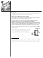
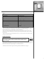
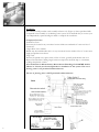
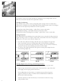
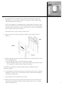
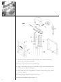
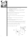
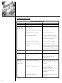
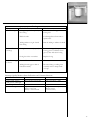
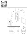
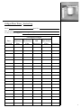
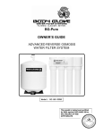
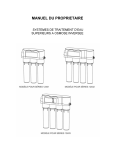
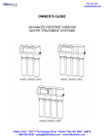
Culligan
Water Tower™
Drinking Water
System
Owners
Guide
NOTICE: This system is intended for use on potable water supplies or disinfected water
containing cysts. Do not use where water is microbiologically unsafe or with water of
unknown quality. If bacterial contamination is present, a recognized method of water
disinfection is required.
Check with your public works department for applicable local plumbing and sanitation codes.
Follow your local codes if they differ from the standards used in this manual.
Operational, maintenance and replacement requirements are essential for this product to perform properly. The Culligan Water Tower™ contains replaceable particulate and activated carbon
filters. It also includes a replaceable reverse osmosis membrane filter which is critical for the
effective reduction of Total Dissolved Solids. The filtered water should be tested periodically to
verify that the system is performing properly.
Culligan International Company
One Culligan Parkway
Northbrook, Illinois USA 60062-6209
847/205-6000
http:\\www. culligan.com
i
Table of Contents
Safety/Warnings ...................................................................................................... i
System Specifications ............................................................................................. 2
Introduction
About Your System ................................................................................. 3
System Component Description ........................................................... 3
Application Guidelines .......................................................................................... 4
Certified Performance ........................................................................................... 5
Installation ............................................................................................................... 6
Servicing Your System ........................................................................................... 7
Cartridge Replacement, Cleaning and Sanitizing Procedure ........................... 8
Troubleshooting Guide ....................................................................................... 14
Parts List ................................................................................................................ 16
Service Log ............................................................................................................ 17
Warranty ................................................................................................................. 18
1
System Specifications
System Flow Sequences ............................... Sediment Filter, Activated Carbon Filter,
Reverse Osmosis Membrane, Storage Tank,
Polishing Filter, Dispensing Faucet.
Sediment Filter .............................................. Spun Polypropylene Type
Carbon Filter ................................................. Activated Carbon Block
Reverse Osmosis Membrane ...................... Thin Film Composite Type
System Daily Production Rate
to Pressurized Storage Tank1 ...................... 11 gpd
Product Production Rate without
Storage Tank to Atmosphere2 ................................... 35 gpd
Ratio of Product to Flush Flow3
Soft Water Applications ....................... 1:1
Hard Water Applications ..................... 1:3 - 1:5
Polishing Filter .............................................. Activated Carbon Block
Dispensing Faucet ........................................ Culligan® Smartap® Rotary Operation,
Stainless Steel and Resin Flow Passages, with
Built-in Siphon Break and Quality Monitor
Color Options ....................................... Polished Chrome, Satin Chrome, White, Black,
Black/Chrome, Almond
Storage Capacity ........................................... 3 gallons (max.)
2.4 gallons (nom.)
Dimensions
Filter Assembly ...................................... 15.5”W x 6”D x 15”H
Storage Tank .......................................... 11” Diameter x 15.5”H
1 Rating at 50 psi, 77°F, 500 mg/L TDS influent.
2 This is a factory specification for membrane production. Actual production rate and TDS
reduction will depend on temperature, water pressure, TDS level, membrane variation and usage
pattern.
3 May vary with pressure. See Technical Manual for all hard water applications and applications
where TDS exceeds 1000 mg/L (ppm).
2
Introduction
Thank you for choosing a Culligan Water Tower™ drinking water system. Your new system is
designed to bring you years of healthful, deliciously crystal-clear Culligan® water. With its special
faucet installed on your sink, it’s like getting bottled water straight from your kitchen tap.
With the Culligan Water Tower drinking water system, you’ll get a continuous supply of clear,
refreshing water for drinking and cooking. But Culligan improves a lot more than just water.
Crystal clear Culligan water is ideal for:
• coffee
• recipes
• pasta
• tea
• baby formula
• ice cubes
• soup
• houseplants
• steam irons
• juice
• pets
• drink mixes
• everything you make with water
With three separate water treatment technologies and its unique space-saving design, the
Culligan Water Tower drinking water system is the most advanced drinking water system available from Culligan today.
About Your System
The reverse osmosis method of water treatment has long been regarded as one of the most
efficient and effective ways to reduce impurities. It’s the technology we’ve used to build your
new Culligan Water Tower drinking water system. In addition, we’ve incorporated activated
carbon and fine particle filtration to bring you one of the most effective systems available today.
Culligan Water Tower System Components
Refer to Figure 2, page 6
Sediment Filter
The sediment filter screens out dirt, sand, rust, and other microscopic particles 15 times smaller
than a grain of sand.
Activated Carbon Filter
The activated carbon filter gets rid of bad tastes and odors, including chlorine, if present in your
untreated water supply.
Reverse Osmosis Membrane Cartridge
The reverse osmosis (RO) membrane squeezes out dissolved substances, including radium, lead,
and many others. These substances may not be in your water. See Performance Data Sheet for
list of substances and removal percentages.
Manifold Assembly
The manifold serves as the functional hub of the system, directing and regulating the flow
through each of the system’s components. It makes the Culligan Water Tower drinking water
system extremely space efficient and simplifies filter changes.
Storage Tank
The storage tank holds Culligan® water under pressure for rapid delivery.
3
Polishing Filter
The Culligan Water Tower™ drinking water system includes a second activated carbon filter in
the manifold as added assurance that your water will be crystal clear.
Culligan® Smartap® Water Quality Monitor and Faucet
The special drinking water faucet mounts conveniently on your kitchen sink. A simple twist of
the handle is all it takes to enjoy refreshing Culligan drinking water.
Your Culligan Water Tower incorporates a proven performance indicator. The patented
Smartap® Water Quality Monitor uses dual probe LOGIC PULSE MEMORY
technology to accurately indicate membrane performance. A split-second power pulse compares
feed water Total Dissolved Solids (TDS) level with that of the product water. Then, by reversing
the polarity of the electronic pulse, the probes are cleaned and kept free of chemical plating.
Electronics from the Culligan Water Tower connected to the Smartap faucet provides feedback
on system operation.
Indications appear in a light bar integrated into the faucet body
front cover (Figure 1). Power is provided through a nine-volt
alkaline battery. To prolong battery life, indicator lights selfextinguish after a few seconds even if water is being dispensed.
- Green means quality Culligan water
- Orange tells you that a service check is necessary
- Yellow means a filter change is required
FIG. 1
Application Guidelines
The Culligan Water Tower drinking water system is designed for use on potable water supplies
meeting the guidelines outlined in Table 1. The system should be installed on your home’s cold
water line. The flushing stream should discharge through an approved siphon break as illustrated
in Figure 2, page 6. Installation of this system must comply with state and local laws and regulations.
4
Table 1
Pressure1
Temperature
Total Dissolved Solids (TDS)2
pH
Chlorine3
Chloramine
Turbidity
Silt Density Index (SDI)
Hardness (CaCO3)
Hydrogen Sulfide (H2S)
Manganese (Mn)
Iron
Bacterial Quality4
Influent Water Characteristics
35-100 psi (242-690 kPa)
40-100°F (4-38°C)
0-2000 ppm (0-2000 mg/L)
3.0 - 11.0
0-2 ppm (0-2 mg/L)
0-2 ppm (0-2 mg/L)
<1.0 NTU
<4
<350 ppm
0.00 ppm
<0.05 ppm
0-1 ppm (0-0.1 mg/L)
Potable
A pressure regulator is recommended for feed water pressures exceeding 80 psig (552 kPa)
See the Technical Manual for all applications where TDS exceeds 1000 ppm (1000 mg/L) to calculate
effective module pressure. A booster pump is strongly recommended.
3
The reverse osmosis membrane filter used in this system may be damaged by chlorine. This system
includes activated carbon which protects this element by reducing chlorine. Influent chlorine should not
exceed 2 mg/L.
4
Do not use with water that is microbiologically unsafe or of unknown quality without adequate disinfection before or after the system.
1
2
Certified Performance
System Tested and Certified by NSF International against ANSI/NSF Standard 58
for the reduction of: Barium, Cadmium, Copper, Fluoride, Hexavalent Chromium,
Lead, Radium 226/228*, Selenium, Total Dissolved Solids, Trivalent Chromium,
Cysts, and Turbidity
The substances removed by this system are not necessarily in your untreated water. See
Performance Data Sheet for percentages of contaminant removal.
* Minimum removal based on approved testing methods with Barium as surrogate.
5
Installation
This Owner’s Guide provides visual assembly reference only (Figure 2). Since specialized skills
are required in the assembly of the drinking water system, we recommend that you contact your
local independently operated Culligan® dealer to complete this installation.
Component Location
Product Water Faucet
Faucet may be located in any convenient location. Make sure underside of location is free of
obstruction.
Culligan Water Tower™ Module*
Module may be installed under sink or in any convenient location within 15 feet of source water
supply and product water faucet.
Storage Tank
Tank may be placed in any space within 15 feet of faucet, generally under kitchen sink or in
adjacent unused cabinet. Tubing length between components should be kept to a minimum,
avoiding sharp bends or kinks.
*For installations in Massachusetts, Massachusetts Plumbing Code 248CMR shall be
adhered to. Consult your licensed plumber for installation of this system. The use of
piercing valves is not permitted in Massachusetts.
The use of piercing valve is NOT permitted in Massachusetts.
FIG. 2
6
Servicing Your System
Service Schedule
When properly maintained, your Culligan Water Tower™ drinking water system will give you
years of dependable service. Use the following as a guide to get the most out of your system.
Service frequency may vary depending on your local water conditions. High sediment, chlorine,
turbidity or hardness levels may require more frequent service.
At least once per year
Replace:
• Sediment Filter Cartridge (Item 7)
• Activated Pre-Carbon Filter Cartridge (Item 8A)
• Activated Post-Carbon (Polishing) Filter Cartridge (Item 8B)
Check:
• RO Membrane Cartridge (Item 9)
- TDS Reduction Performance
- Flow Rates - Concentrate & Product
• Flow Control (Item 6)
Clean and Sanitize the System
Use the convenient chart inside the back cover of this booklet to keep track of your system’s
maintenance.
Equipment Needed
• Safety glasses
• Rubber gloves, sanitary
• Wash cloth, clean and lint-free
• Liquid dish soap
• Household bleach - unscented only (5-1/4% sodium hypochlorite)
• Plastic storage bag
• Manual air pump
• Plastic bucket
• Plastic bowl
• Silicone lubricant, FDA approved
Have all components and supplies on-hand and ready before beginning procedure.
A clean work area and equipment are essential to properly clean and/or sanitize the system (i.e.,
clean hands, tools, work surface and containers).
Cartridge Replacement
Culligan recommends that you have your Culligan Water Tower drinking water system serviced
by your local Culligan Man™. You can rely on his or her experience and expertise to keep your
system in top operating condition.
7
If you wish to service your system, the filters are available from your Culligan dealer. See the
Parts List at the end of this section for replacement numbers.
Cartridge Conditioning
The activated carbon, reverse osmosis, and polishing filter cartridges must be conditioned as
follows prior to installation into the Culligan Water Tower™ drinking water system. Your Culligan
Man™ can do these important procedures at the time of purchase.
Activated Pre-Carbon Filter Cartridge - 2 gallon flush to remove carbon dust
RO Membrane Cartridge - 6 hour flush to remove preservative solution
Activated Post-Carbon (Polishing) Filter Cartridge - 2 gallon flush to remove carbon dust
Tubing Connectors
The Culligan Water Tower drinking water system features easy-to-use push-in tubing connectors
(Figure 3). Fittings consist of two parts: a body and a colored collet. Collet color corresponds to
tubing color to be used at that connection (Figure 3A).
1. To install a tube, lubricate the tubing end with water (only) and push it through collet
until it seats firmly at bottom of fitting (Figure 3B). You should feel the tubing pass
the O-rings. Cut ends must be square. Be sure the tubing is smooth and free of abrasions,
otherwise a leak may result. Cut tubing only with a new razor blade.
2. To remove a tube, push and hold the collet against the fitting body and pull the tube
from the fitting. (Figure 3C).
FIG. 3A
FIG. 3B
FIG. 3C
Cartridge Replacement, Cleaning and Sanitizing Procedure
1. Mix a mild cleaning solution of dish soap and clean potable water in plastic bowl.
2. Empty storage tank and relieve system pressure. Verify tank valve is open. Close feed
water supply valve and open product water faucet.
Note: Additional point-of-use devices (i.e. icemakers) may use filters along their
supply line. Remove any filter or treatment device installed between module and
delivery device before preceding.
8
Icemaker: Transfer ice cubes from bin/tray to clean freezer container for storage
until procedure is done.
3. Check product water storage tank air pre-charge using low-pressure gauge (PN
34002024). Air valve is located on tank base. Pre-charge should be 55 kPa (8 psig)
with tank empty and tank valve open.
Note: Use hand pump to avoid damaging tank. Verify product water faucet is open
before proceeding. Use caution when working with/inside enclosure. Wiring therein
connects monitor components. If wires, circuit board, or connections are damaged
and/or wetted, monitor will not function.
Item callouts refer to Figure 5 unless otherwise noted.
4. Remove enclosure front panel by pressing in push-in tabs and pull cover back.
(Figure 4)
FIG. 4
5. Remove each filter housing (Item 30) by turning it counter-clockwise. Remove each
filter cartridge (Figure 5).
a. Discard sediment (Item 7) and carbon (Item 8) cartridges
b. Examine membrane (Item 9). If it is performing satisfactorily, proceed to Step 6.
If it is depleted or fouled, discard it and proceed to Step 8.
Note: Wear gloves whenever cleaning/sanitizing system or handling new filter/
membrane cartridges.
6. Clean membrane outer wrap with washcloth and cleaning solution. Do not immerse
membrane in solution. Do not scrub wrap with abrasive cleaners. Rinse membrane
well with clean potable water.
7. Place membrane into clean plastic bag, close bag.
8. Remove filter housing O-rings and wash them with cleaning solution. Rinse them
well with clean potable water. Inspect them for damage such as nicks or scratches.
Replace damaged O-rings.
9
FIG. 5
9. Clean filter housings/manifold, inside and outside, with washcloth and cleaning
solution. Do not use abrasive materials.
10. Rinse housings/manifold with clean potable water.
11. Inspect filter housing O-ring groove and manifold O-ring surface for damage such as
nicks or scratches. Replace if damaged.
12. Place a small amount of O-ring lubricant on surface of filter housing O-ring. Install
O-ring into housing.
TO SANITIZE THE SYSTEM: Complete Steps 13-33.
TO INSTALL FILTERS: Complete Steps 20-33.
10
CAUTION: Wear safety glasses while performing this procedure.
CAUTION: Read “WARNINGS” information on bleach container
before using contents. Handle sanitizing solution carefully. Avoid
contact with unprotected areas.
13. Mix sanitizing solution of 1.5 ml (1/3 teaspoon) of household bleach and 3.8 L
(1 gallon) of clean, potable water in the bucket. Mix solution well.
Note: Excessive concentrations of bleach (sodium hypochlorite) may damage plastic and rubber
components. Rinse all parts that contact bleach thoroughly with clean potable water.
14. Add 236 ml (one cup or 8 oz.) of sanitizing solution to each filter housing and install
them onto the manifold (do not install filters or membrane at this time). Tighten
each filter housing by hand only.
Note: Tighten filter housings by hand only. Do not use tools as they will over-tighten and
damage housings.
15. Slowly open source water supply valve.
16. Close product water faucet as soon as water begins to flow from spout.
17. Wait 5 minutes, then close source water supply valve.
18. Wait 25 minutes, then open product water faucet. Let water flow to drain until
system is drained (flow stops), then close faucet.
Note: Remove filter housings only after water flow stops.
19. Remove filter housings and dispose of water. Rinse housings/manifold thoroughly
with clean, potable water.
Note: Do not remove protective plastic bag from replacement filter and membrane cartridges.
Note: For optimum monitor performance, the monitor must be re-set and the battery replaced
each time system is sanitized. However, a technician may wait until indicator lights fail to illuminate to replace battery.
20. Hold cartridge by its protective plastic bag and open protective bag to expose
cartridge cap and O-rings.
11
21. Install cartridges. (Refer to Figure 5 for location of each cartridge).
a. Hold cartridge by its protective plastic bag.
b. Insert cartridge into manifold turning it 1/2 turn as it enters port. Slide bag from
cartridge and discard.
c. Install filter housing (Item 30) as each cartridge is inserted. Make sure housing
o-ring is properly lubricated.
Note: Tighten filter housings by hand only. Do not use tools as they will over-tighten and
damage housings. Take care not to cut or pinch the O-rings.
22. Turn feed water valve slowly to open position.
23. Confirm system is producing water. Unit will be sending rinse water to drain. Check
for leaks.
Note: Monitor must be re-set each time the system is serviced to ensure accurate
monitor performance.
TO RE-SET MONITOR or TO CHANGE BATTERY: Perform Steps 24-27
Refer to Figure 6 for component location.
Use caution when working inside enclosure. Wiring therein connects monitor components. If
wires, circuit board, or connections are damaged and/or wetted, monitor will not function.
Connect battery to monitor after system has been in production mode for at least 5 minutes.
This ensures sensing switch is in proper position to record data.
24. Disconnect battery. The connection is a snap type connector.
25. Remove battery by sliding it out of its holder.
FIG. 6
12
Note: Replace battery with a new alkaline 9-volt battery (PN 31300001)
26. Carefully slide battery into its holder.
27. Connect battery by pressing clip onto battery terminals.
28. Test monitor connection by activating monitor. Open product water faucet. If an
indicator light illuminates, connection is good.
Note: Close faucet immediately after light illuminates. Test confirms battery connection, not
water quality.
29. Install enclosure front panel (Item 3):
a. Place panel in position, aligning push-in tabs with openings. Verify circuit board
wiring is not pinched between panels.
b. Press panel inward until push-in tabs engage, securing the panel.
c. Check for leaks.
30. Open product water faucet. Let water flow until all air has been expelled from the
system.
31. Close product water faucet. Wait 30 minutes, check connections for leaks, and
correct if necessary.
Icemaker/Extra point of use: Check lines for leaks.
32. Allow storage tank to fill overnight.
DO NOT USE FIRST FULL STORAGE TANK OF WATER
33. Discard (to drain) first full tank of water by opening product water faucet until water
flow stops, then close faucet. This flushes sanitizing solution from system.
Icemaker: Let tray/bin fill with ice cubes. Discard all ice cubes to drain. This flushes sanitizing
solution from lines in icemaker. Replace delivery device filter (if applicable).
Note: System is ready to use. Should there be any aftertaste or odor, drain storage tank and
repeat Steps 32 and 33.
13
Troubleshooting Guide
14
Symptom
Water Volume and Quality
Condition
Action
No product water
Water supply is turned OFF
Turn water ON
Not enough
product water
Low water pressure
Check source water line pressure
Inlet water supply valve is blocked
Clear restriction
Storage tank valve is closed
Open storage tank valve
Storage tank is depleted
Increase product water storage
capacity and/or install membrane
with higher output rating
Clogged pre-filter cartridge(s)
Replace pre-filter cartridge(s)
Storage tank air pressure charge
is low
Empty water from storage tank
(product water faucet must remain
open while adjusting pressure) and
adjust pressure to 55 kPa (8 psig)
System does not
shut off
Shut-off valve is not closing
Contact your Culligan® Dealer
No drain water
Clogged flow control
Replace flow control (Item 6) in
parts list and contact your
Culligan® Dealer
Water has
offensive taste
and/or odor
Carbon post-filter is depleted
Drain storage tank, sanitize system
and replace carbon post-filter
cartridge
Membrane depleted or fouled
Smartap® Quality Monitor reads
yellow, or if TDS test is
unsatisfactory, drain storage tank,
sanitize system and replace
membrane
Sanitizer not flushed out
Drain storage tank and let it refill
overnight
Leakage
Symptom
Probable Cause
Solution
Leak at fitting
Tubing not pushed completely
into fitting
Push tube into fitting past
O-ring seal
Defective tube
Cut damaged area from tube or
replace tube
Tubing makes too tight a bend
near fitting
Run the tubing to reduce the bend
O-ring has not seated properly
Remove O-ring and inspect
O-ring groove for debris. Clean
groove, lube and reseat O-ring
O-ring has nicks or scratches
Replace O-ring
Restricted drain tube
Clear restriction
Tubing from air gap to drain is
routed incorrectly
Re-route tubing so tubing runs
vertically with no sharp bends
or loops
Leak at filter
housings
Leak from air gap
in faucet
Smartap® Quality Monitor Status Indications and Common Solutions
Indication
Green Light
Orange Light (appears
with green or yellow light
Yellow Light
No Monitor Lights
Condition
System operating normally
Shut-off valve is not closing
Action
None
Call your Culligan® dealer
Membrane exhausted
Light Assembly is not connected
Battery voltage low
Battery is not connected
Replace membrane
Plug connector into phone jack
Replace battery
Connect battery
15
Parts List
Item
1
2
4
5
6
7
8
9
10
11
12
Description
Culligan Faucet, Chrome body/spout
Culligan Faucet, White body/spout
Culligan Faucet, Almond body/spout
Culligan Faucet, Black body/spout
Culligan Faucet, Satin body/spout
Culligan Faucet, Black body/Polished spout
Battery, 9-volt alkaline
Bracket, Mounting
Screw, Mounting Bracket
Flow Control, Green Tape
Cartridge, Sediment Culligan®
Cartridge, Carbon Culligan®
Cartridge, RO Membrane Green Casing - Purple Tape Culligan®
Tank, Product Water Storage - White
Valve, Shut-off w/O-ring
Elbow, 3/8” Stem w/white collet
Gauge Air Pressure
Part Numbers in bold italics are Valencia, CA Part Numbers
16
Part No.
11403430
11403431
11403433
11403434
11403436
11403439
31300001
21100101
32701002
40600037
01013028
01013029
41402004
34500003
33503601
33503504
34002024
Culligan Water Tower™ Service Log
Model
Date Installed
For Service Call Culligan at: (
Date
Serviced
Sediment
Filter
Serial No.
)
—
Cartridge(s) Changed
Activated
Activated
Pre-Carbon
RO
Post-Carbon
Filter
Membrane
Filter
Sanitized
17
Culligan Lifetime Limited Warranty
CULLIGAN WATER TOWER™ CWT-35 MODEL SERIES
You have just purchased one of the finest drinking water systems made. As an expression of our
confidence in Culligan International Company products, your drinking water system is warranted to the
original end-user, when installed in accordance with Culligan specifications, against defects in material
and workmanship from the date of original installation, as follows:
For the LIFETIME of the
original end-user
The entire reverse osmosis drinking water appliance,
EXCLUDING THE EXPENDABLE FILTER CARTRIDGES AND
REVERSE OSMOSIS MEMBRANE FILTER USED IN THIS APPLIANCE.
Pro rata for a period
of ONE YEAR
The original Culligan reverse osmosis membrane filter. Culligan will
reduce the cost of a replacement Culligan reverse osmosis
membrane filter by 1/12th of the then-current manufacturer's
suggested retail price for each month remaining in the year period
when the defect is found and confirmed by a Culligan dealer.
If a part described above is found defective within the specified period, you should notify your independently operated Culligan dealer and arrange a time during normal business hours for the dealer to inspect
the drinking water appliance on your premises. Any part found defective within the terms of this warranty
will be repaired or replaced by the dealer. If any part is found defective, Culligan also reserves the right to
replace the drinking water appliance with a comparable Culligan drinking water system of equal or greater
quality. You pay only freight for repaired or replaced parts from our factory and local dealer charges,
including but not limited to labor charges, travel and transportation expenses and handling fees.
Damage caused by accident, fire, flood, freezing, Act of God, misuse, misapplication, neglect, alteration,
installation or operation contrary to our printed instructions, or by the use of accessories or components
which do not meet Culligan specifications, is not covered by this warranty.
ALL IMPLIED WARRANTIES, INCLUDING WITHOUT LIMITATION WARRANTIES OF MERCHANTABILITY AND FITNESS FOR PARTICULAR PURPOSE, ARE LIMITED IN DURATION TO THE PERIOD SPECIFIED ABOVE FOR THE PARTS DESCRIBED IN THIS LIMITED WARRANTY. As a manufacturer, we do
not know the characteristics of your water supply. The quality of water supplies may vary seasonally or
over a period of time. Your water usage rate may vary as well. Water characteristics can also change if
your drinking water appliance is moved to a new location. For these reasons, we assume no liability for
the determination of the proper equipment necessary to meet your requirements, and we do not authorize
others to assume such obligations for us. Further, we assume no liability and extend no warranties,
express or implied, for the use of this product with a non-potable water source or a water source which
does not meet the conditions for use described in the Owner's Guide and Performance Data Sheet.
CULLIGAN'S OBLIGATIONS UNDER THIS WARRANTY ARE LIMITED TO THE REPAIR OR
REPLACEMENT OF THE FAILED PARTS OF THE DRINKING WATER APPLIANCE, AND WE ASSUME
NO LIABILITY WHATSOEVER FOR DIRECT, INDIRECT, INCIDENTAL, CONSEQUENTIAL, SPECIAL,
GENERAL, OR OTHER DAMAGES, WHETHER FROM CORROSION OR OTHER CAUSES.
Some states do not allow limitations on how long an implied warranty lasts, so the above limitation
may not apply to you. Similarly, some states do not allow the exclusion of incidental or consequential damages, so the above limitation or exclusion may not apply to you. This warranty gives you
specific legal rights, and you may also have other rights which vary from state to state. Consult
your telephone directory for your local independently operated Culligan dealer, or write Culligan
International Company for warranty and service information.
CULLIGAN INTERNATIONAL COMPANY
One Culligan Parkway
Northbrook, Illinois 60062
18
01882203 (36105001*) DCO#1254
©2000 Culligan International Company
Printed in USA (Rev A. 8/21/00)
Materials & description: 8-1/2 x 11, 20 page book, saddle stitched, three hole punched - Prints black
ink on 50# offset white
LET
A
CHANGE
DCO 1254
BY APRVD
TPD
BL
DATE
8/21/00
This page contains materials and DCO
information. IT DOES NOT PRINT AS
PART OF THE DOCUMENT!