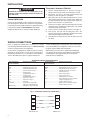
1
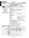
1F98EZ-1421, -1441 Easy Install
For up to 4 Stages Heat and 2 Stages Cool
INSTALLATION INSTRUCTIONS
FAILURE TO READ AND FOLLOW ALL INSTRUCTIONS CAREFULLY BEFORE
INSTALLING OR OPERATING THIS CONTROL COULD CAUSE PERSONAL
INJURY AND/OR PROPERTY DAMAGE.
APPLICATIONS
Configuration
Options
Applications
Single Stage
Gas, Oil, Electric, Heat Only, Cool
Only or Heat Cool Systems
1/1
Multi Stage
Gas, Oil, Electric, Heat Only, Cool
Only or Heat Cool Systems
2/2
Heat Pump
Single or Two Compressor Systems
with up to 2 Stages of Aux / Em Heat
4/2
Heat Pump
with Dual Fuel
Single or Two Compressor Systems
with up to 2 Stages of Fossil fuel
Heat
4/2
1F98EZ-1421, -1441 System
Maximum
Stages
12” Touchscreen User Interface
1F98-1491
Equipment Control
40C01-1400
SPECIFICATIONS
Electrical Rating:
Input-Hardwire.................................................... 20 to 30 VAC
Terminal Load............................................................ 1.0A per terminal, 2.5A maximum all terminals combined
Setpoint Range.......................................................... 45° to 99°F (7° to 37°C)
Differential (Single Stage).......................................... Heat 0.6°F; Cool 1.2°F
Differential (Multi-Stage)............................................ Heat 0.6°F; Cool 1.2°F
Differential (Heat Pump)............................................ Heat 1.2°F; Cool 1.5°F
Operating Ambient..................................................... 32°F to +105°F (0° to +41°C)
Operating Humidity.................................................... 90% non-condensing max.
Shipping Temperature Range.................................... -40° to +150°F (-40° to +65°C)
Dimensions Interface................................................. 4-1/2”H x 6”W x 1-1/4”D
Dimensions Control................................................... 5-1/2”H x 5-3/4”W x 1-1/2”D
! CAUTION
To prevent electrical shock and/or equipment damage,
disconnect electric power to system at main fuse or
circuit breaker box until installation is complete.
Index
Page
Installation
2
Wiring Connections
2
Wiring Diagrams
3
Installer Configuration Menu
5
Troubleshooting
8
ATTENTION: MERCURY NOTICE
This product does not contain mercury. However, this
product may replace a product that contains mercury.
Mercury and products containing mercury must not be
discarded in household trash. Do not touch any spilled
mercury. Wearing non-absorbent gloves, clean up any
spilled mercury and place in a sealed container. For proper
disposal of a product containing mercury or a sealed
container of spilled mercury, place it in a suitable shipping
container. Refer to www.white-rodgers.com for location to
send product containing mercury.
PART NO. 37-7215C
www.white-rodgers.com
www.emersonclimate.com
Replaces 37-7215B
1110
1
INSTALLATION
!
Thermostat / Interface 1F98-1491
WARNING
Thermostat installation and all components of the
control system shall conform to Class II circuits per
the NEC code.
Control 40C01-1400
Control can be mounted on wall or equipment. Control has
four mounting holes. Wall anchors and screws are provided
for mounting on drywall. Drill 3/16 hole for drywall mounting.
If mounting on equipment Do Not Mount inside HVAC
equipment. Only mount on outside of HVAC equipment.
1) Pull the thermostat/interface off the base. Forcing or
prying on the thermostat will cause damage to the unit.
2) Place base over hole in wall and mark mounting hole
locations on wall using base as a template.
3) Move base out of the way. Drill mounting holes. If you are
using existing mounting holes and the holes drilled are
too large and do not allow you to tighten base snugly, use
plastic screw anchors to secure the base.
4) Fasten base snugly to wall using mounting holes and two
mounting screws. Leveling is for appearance only and will
not affect thermostat operation.
5) Connect wires to terminal block on base (see Figure 1).
6) Push excess wire into wall and plug hole with a fire
resistant material (such as fiberglass insulation) to prevent
drafts from affecting thermostat operation.
7) Carefully line the thermostat up with the base and snap
into place.
WIRING CONNECTIONS
Refer to equipment manufacturers’ instructions for specific
system wiring information. After wiring, see CONFIGURATION
section for proper thermostat configuration.
control will display E (for communication error) until interface
is connected. With power supplied to control, it is normal for
the green system LED to flash periodically.
Connect wires as appropriate for HVAC systems (see wiring
diagrams). To power control, connect the 24 V system hot to
R terminal and common to C on left side of control labelled
“Power”. On initial power up the 7 segment LED on the
With interface connected, the 7 segment LED will display
C to indicate the two devices have initiated communication.
C will disappear after approximately 30 seconds when
communication is established.
BLUE EASY INSTALL INPUTS/OUTPUTS
Easy Install 40C01
Control Terminals
Operational / Functional.
R..........................................24 VAC Transformer
RC........................................24 VAC Cooling Transformer
RH........................................24 VAC Heating Transformer
C..........................................24 V Transformer Common
W/E......................................Heating Stage 1
HP Aux/Em Heat Stage 1
W2........................................Heating Stage 2
HP Aux/Em Heat Stage 2
Y...........................................Compressor Stage 1
Y2.........................................Compressor Stage 2
G...........................................Fan Relay
L Terminal.............................System Monitor Compatible
with Comfort Alert Diagnostics
O/B Terminal.........................Changeover Relay Heat Pump
Easy Install 40C01
Control Terminals
Operational / Functional.
DHM.....................................Dehumidification Relay / Connection
DHM2...................................Dehumidification Relay / Connection
HM........................................Humidification Relay / Connection
HM2......................................Humidification Relay / Connection
R...........................................24 VAC to Interface
1...........................................Data to/from Interface
2...........................................Data to/from Interface
C...........................................24 VAC Common to Interface
RJ11.....................................Field configuration hook-up with RJ11
equipped configuration tool.
+...........................................Voltage to Outdoor Sensor
S...........................................Outdoor Sensor Temperature Signal
-............................................Voltage to Outdoor Sensor
Fig. 1 - Thermostat / Interface to control wiring
R
R
1
1
2
2
C
1F98 Thermostat
2
C
40C01Control
WIRING DIAGRAMS
Fig. 2 - Typical Connection of a Single Stage or Multi-Stage System
*
SYSTEM
R
Single
Stage
24 VAC
Power
Multi
Stage
24 VAC
Power
RH
RC
C
24 VAC
24 VAC
Power
Power
for Heating for Cooling
24 VAC
Power
24 VAC
Power
24 VAC
Common
Required
W/E
W2
Y
Y2
G
O/B
L
Heat
N/A
Cool
N/A
Fan
N/A
System
Monitor
Heat
mode
1st
stage
Heat
mode
2nd
stage
Cool
mode
1st
stage
Cool
mode
2nd
stage
NEUTRAL
120 VAC
24 VAC
HOT
*Factory installed jumper between RH and RC
CLASS II
Transformer
Fig. 3 - Typical Connection of Heat Pump System up to 4 Stages Heat / 2 Stages Cool
*
SYSTEM
Heat
Pump
R
RH
RC
C
24 VAC 24 VAC 24 VAC 24 VAC
Power Power Power Common
for
for
Required
Heating Cooling
W/E W2
Y
Y2
G
O/B
L
Aux / Aux /
1st stage
2nd stage
Fan Changeover System
Em
Em Compressor Compressor
Valve
Monitor
1st
2nd
stage stage
NEUTRAL
120 VAC
24 VAC
HOT
*Factory installed jumper between RH and RC
CLASS II
Transformer
Fig. 4 - Typical Connection of Heat Pump / Dual Fuel System up to 4 Stages Heat / 2 Stages Cool
SYSTEM
Heat
Pump
R
*
RH
RC
C
24 VAC 24 VAC 24 VAC 24 VAC
Power Power Power Common
for
for
Required
Heating Cooling
W/E W2
Y
Y2
G
O/B
L
Fossil Fossil 1 stage
2 stage
Fan Changeover System
Fuel Fuel Compressor Compressor
Valve
Monitor
1st
2nd
stage stage
st
nd
NEUTRAL
24 VAC
120 VAC
HOT
*Factory installed jumper between RH and RC
CLASS II
Transformer
3
WIRING DIAGRAMS
Wiring Guide for Equipment Accessories
Fig. 5 - Non-Powered Humidifier. HM terminal provides system 24 V on call for humidification
HM DRY
R
RH
HM
Non-Powered
Humidifier
HM2
C
HM2
Transformer
Fig. 6 - Powered Humidifier. With HM DRY switch in HM2 position, HM and HM2 provide normally
open dry contact for low voltage (24 V) powered humidifier connection.
HM
HM DRY
RH
Powered
Humidifier
HM2
HM2
Fig. 7 - Powered Dehumidifier. With DHM DRY switch in DHM2 position, DHM and DHM2 provide
normally open dry contact for low voltage (24 V) whole house powered dehumidifier connection.
RH
DHM2
DHM
Powered
Dehumidifier
DHM2
DHM DRY
Fig. 8 - System Dehumidification with variable speed blower. For systems where low speed requires connect to normally
open 24 V powered DHM terminal for low speed connection on air handler / furnace (24 V removed on dehumidification call).
DHM
RH
Low Speed
Fan
DHM2
DHM2
DHM DRY
Fig. 9 - System Dehumidification with variable speed blower. For systems where low speed requires system 24 V on
dehumidification connect 24 V to DHM2 with DHM DRY switch in DHM2 position and connect DHM to low speed
connection on air handler/ furnace.
R
C
Transformer
4
RH
DHM2
DHM DRY
DHM
DHM2
Low Speed
Fan
INSTALLER/CONFIGURATION MENU
Entering and Navigating the Advanced Installer Configuration Menu
On the Home Screen Display, touch the Menu key to display additional key choices. Touch and hold the Installer Config key
for approximately 3 seconds to enter the Thermostat Options Configuration Menu. Touch and hold the Installer Config key
again for approximately 3 seconds to enter the Advanced Installer Configuration Menu.
Press
or
Key
to Select Options
Displayed in
Message Area
Ref.
#
Description of
Features in order when
using
to choose;
(Use
to step back)
Displayed in
Clock Digits
(Default)
Options
1
Outdoor / Condenser
Configuration
AC1
AC0, AC1, AC2, HP1, HP2
CONDENSER
CONFIG
2
Indoor Heat
Configuration
GA2
FAN, GA1, GA2, EL1, EL2
INDOOR HEAT
CONFIG
3
B or O terminal
(HP1, HP2 only)
O
O, b
REVERSING VALVE
4
Heat Cycle Rate
FA
SL, FA
HEAT CYCLE RATE
5
Cool Cycle Rate
FA
SL, FA
COOL CYCLE RATE
6
Auxiliary Cycle Rate
(HP1, HP2 only)
FA
SL, FA
AUXILIARY CYCLE
RATE
7
Energy Management
Recovery
On
OFF, On
ENERGY MANAGEMENT
RECOVERY
8
Outdoor Remote
Sensor
OFF
OFF, On
OUTDOOR REMOTE SENSOR
9
Auxiliary Off
(HP1, HP2 only)
OFF
OFF, 35-80 (in steps of 1 degree)
From OFF, value changes to 80
AUXILIARY OFF
10
Dual Fuel Config
(HP1, HP2 only)
40
OFF, 0 to 50 (in steps of 1 degree)
From OFF, value changes to 40
DUAL FUEL CONFIG
DEHUM XX% (where XX
is the DEHUM set point)
11
Dehumidification
OFF
OFF, 40-80 (in 1% steps) - displayed
in the last digits of the Message Area.
From OFF, value changes to 60
12
Independent
Dehumidification
OFF
OFF, On
INDEPENDENT DEHUMID
HUMID XX% (where XX
is the HUM set point)
13
Humidification
OFF
OFF, 20-60 (in 1% steps) - displayed
in the last digits of the Message Area.
From OFF, value changes to 40
14
Independent
Humidification
OFF
OFF, On
INDEPENDENT
HUMID
15
Compressor Lockout
OFF
OFF, On
COMPRESSOR LOCKOUT
5
INSTALLER/CONFIGURATION MENU
Configuration
Control can be configured at the equipment by utilizing the configuration plug in tool (F4-1400). The tool mounts to the back
of the interface and plugs into the bottom of the control via the RJ-11 connection. (Note: You cannot have two interfaces
connected to the control at the same time). With control powered, interface is used to configure the application and for
operational checks. Once configured, the interface can be installed in living area.
1) Outdoor / Condenser Configuration. Select the number type A/C (air conditioner) HP Heat Pump and number
of stages. The appropriate Color (A/C= Amber, Heat
Pump=Green) LED will illuminate for the configured Y/Y2
terminals.
2) Indoor / Heat Configuration. Select the number type
GA (Gas) EL (electric) and Fan and number of stages.
The appropriate Color (Amber if gas, Green if electric)
LED will illuminate for the configured W/W2 terminals.
3) B or O Terminal Configuration. If condenser is heat
pump configured then Select either O (default) or B
terminal output configuration. The B/O LED will illuminate
the appropriate color (Amber if B, Green if O)
4) Heat Cycle Rate. Select either FA fast (default) or SL
slow cycle rate. If longer cycles are desired then set to
SL.
5) Cool Cycle Rate. Select either FA fast (default) or SL
slow cycle rate. If longer cycles are desired then set to
SL.
6) Auxiliary Cycle Rate. If condenser is heat pump select
W/E
either FA fast (default) or SL slow cycle rate. If longer
cycles are desired then set to SL.
7) Energy Management Recovery. Select either On or Off.
With a selection of On the system will start temperature
setback recovery early to reach the program setpoint
W2 at
the program start time. A selection of Off will startYthe
Y2
recovery period at the program start time.
G the
8) Outdoor Remote Sense. A selection of On enables
O/B
display of outdoor temperature with the connection of
F145-1378 outdoor remote sensor to the control. HM
DHM
After Advanced Installer Configuration, LEDs on the control
will indicate the selections of the thermostat. The following
tables show the LED indications. Remove control cover to
Fig. 10 - LED locations
10) Dual Fuel Config. When condenser is heat pump and
indoor heat is gas and outdoor sensor is connected. A
selection from 0 to 50 in one degree increment is available. The Auxiliary/fossil fuel system is enabled, the heat
pump is disabled when the outdoor ambient temperature
is at or below the selection.
11) Dehumidification. Select from Off (default) to a setting
range from 40% to 80% Rh. If Rh is above setting, a
cooling call is initiated. To turn this feature Off raise setting to its highest level 80%
12) Independent Dehumidification. Selection of Off (default) or On. When On is selected the DHM2 output is
active when humidity level is above the desired dehumidification setting.
13) Humidification. Select from Off (default) to a setting
range from 20% to 60% Rh. If Rh is below setting HM2
output is active with a call for heat. To turn this feature Off
lower setting to its lowest level 20%.
Break tab
14)Independent Humidification. Selection of Off (default)
to have LEDs
or On. When On is selected the HM2 output operateson with cover
when humidity level is below the desired humidification
installed
setting.
15) Compressor Lockout. Selection of Off (default) or On.
When On is selected the control will invoke a 5 minute
delay between compressor cycles.
view LEDs. To view LEDs with cover installed, break off tab
on inside of cover.
Fig. 11 - Inside of front cover
Break tab
to have LEDs
on with cover
installed
W/E
W2
Y
Y2
G
O/B
HM
7-Segment
LED for Comfort
Alert and
Communication
Codes
System
DHM
RJ-11 Connection for
Configuration Plug-In tool
6
9) Auxiliary Off. When condenser is heat pump configured
and outdoor sensor is connected, the option of locking
out the auxiliary heat based on outdoor ambient temperature becomes available. Default is Off with a selection range from 80 degrees to 35 degrees in 1 degree
increment. When outdoor ambient is above the selected
temperature the auxiliary stages are disabled.
Fig. 11 - Inside of front cover
INSTALLER/CONFIGURATION MENU
LED Indicator legend:
= Amber
= Green
Off
= Off
LED’s will be on constant to show configuration.
LED’s will flash to indicate the terminal output is active.
Table 1 - System Configuration
System
Type
Conventional
Heat Pump
Dual Fuel
AC Cool
Gas Heat
Electric Heat
Electric System
Outdoor
Equipment
Type
No. of Stages –
Outdoor
Equipment
Type
Indoor
Equipment
Type
No. of Stages –
Indoor
Equipment
Type
AC
1
Gas
1
Off
AC
1
Gas
2
Off
AC
2
Gas
1
AC
2
Gas
2
HP
1
Elec
1
Off
HP
1
Elec
2
Off
HP
2
Elec
1
HP
2
Elec
2
HP
1
Gas
1
Off
HP
1
Gas
2
Off
HP
2
Gas
1
HP
2
Gas
2
AC
1
Elec
0
Y2
Off
AC
2
Elec
0
–
Gas
1
Off
Off
No Outdoor
Unit
–
Gas
2
Off
Off
No Outdoor
Unit
–
Elec
1
Off
Off
No Outdoor
Unit
–
Elec
2
Off
Off
AC
1
Elec
1
Off
AC
1
Elec
2
Off
AC
2
Elec
1
AC
2
Elec
2
1
Elec
0
HP Only (HO)
HP
2
Elec
0
Fan Only
No Outdoor
Unit
–
Elec
0
Table 2 - DHM Bi-Color LED Table
DHM LED
Table 3 - HM Bi-Color LED Truth Table
HM DRY
Switch Position
HM LED
W/E
W2
G
Off
Off
No Outdoor
Unit
HP
DHM DRY
Switch Position
Y
Off
Off
Off
Off
Off
Off
Off
Off
Off
Off
Off
Off
Off
Off
Off
Off
Off
Off
Table 4 - O/B Bi-Color LED Truth Table
Reversing Valve
Configuration
RH
RH
O mode
DHM2
HM2
B mode
O/B LED
7
TROUBLESHOOTING
Reset Operation
If a voltage spike or static discharge blanks out the display or
causes erratic thermostat operation, you can reset the system
by removing batteries for 2 minutes. After resetting the
system, replace the batteries. If the system has been reset
and still does not function correctly perform a power reset.
Note: Be sure to review the installer configuration menu
settings.
Note: When thermostat is reset, installer configuration menu
settings and programming will reset to factory settings.
To reset the programming, clock and configuration
settings, press
and
and the SYSTEM touch keys
simultaneously. The thermostat should go blank and then all
segments will be displayed momentarily.
Symptom
Possible Cause
Correction Action
No Heat/No Cool/No Fan
(common problems)
1.Blown fuse or tripped circuit breaker.
2.Power switch to OFF.
3.Furnace blower compartment door or
panel loose or not properly installed.
4.Loose connection to system.
Replace fuse or reset breaker.
Turn switch to ON.
Replace door panel in proper position to engage safety
interlock or door switch.
Check connections.
No Heat
1.Pilot light not lit.
2.Furnace Lock-Out Condition. Heat
may also be intermittent.
3.Heat pump system requires service.
See fault code table Comfort Alert.
Re-light pilot.
Many furnaces have safety devices that shut down when
a lock-out condition occurs. If the heat works intermittently
contact the furnace manufacturer or local HVAC service
person for assistance.
No Cool
1.Cooling system requires service.
See fault code table Comfort Alert.
1.Possible short in wiring.
2.Possible short in thermostat.
3.Possible short in heat/cool/fan system.
4.FAN Switch set to Fan ON.
Check each wire connection to verify they are not shorted
or touching together. No bare wire should stick out from
under terminal block. Try resetting the thermostat as
described above. If the condition persists the manufacturer
of your system or service person can instruct you on how
to test the Heat/Cool system for correct operation. If the
system operates correctly, replace the thermostat.
Thermostat Setting &
Thermostat Thermometer
Disagree
1.Thermostat display setting
requires adjustment.
The display can be adjusted +/- 5 degrees. See
Temperature Display Adjustment in the Configuration Menu
section.
Furnace (Air Conditioner)
Cycles Too Fast or Too
Slow (narrow or wide
temperature swing)
1.The location of the thermostat and/or
the size of the Heating System may
be influencing the cycle rate.
Digital thermostats provide precise control and cycle faster
than older mechanical models. The system turns on and off
more frequently but runs for a shorter time so there is no
increase in energy use. If you would like an increased cycle
time, choose SL for slow cycle in the Configuration menu.
Heat, Cool or Fan
Runs Constantly
Comfort Alert™ Fault Codes
Number Displayed in
7 Segment LED
Comfort Alert Fault
P
1
Trip
Long Run Time
2
3
4
5
6
7
8
9
System Pressure Trip
Short Cycling
Locked Rotor
Open Circuit
Open Start Circuit
Open Run Circuit
Welded Contactor
Low Voltage
System Communication Codes
E
C
Communication Error
For 30 seconds after Communication
established, then blank
White-Rodgers is a division
of Emerson Electric Co.
The Emerson logo is a
trademark and service mark
of Emerson Electric Co.
8
www.white-rodgers.com
www.emersonclimate.com