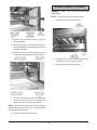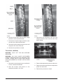
1
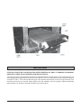
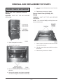
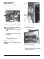
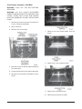
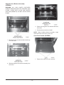
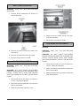
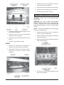
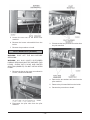
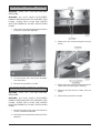
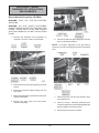
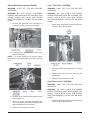
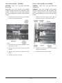
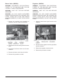
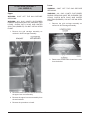
SERVICE MANUAL
HEAVY DUTY GAS BROILER
MODELS
GHCB40
GHCB44
GHMCB44
HCB1
HCB2(B)
IR1
IR2(B)
GHIR44
ML-052211
ML-052213
ML-052214
ML-052202
ML-052208
ML-052200
ML-052201
ML-052210
GHCB40 SHOWN
– NOTICE –
This Manual is prepared for the use of trained Vulcan Service Technicians and should not be used by those not properly
qualified. If you have attended a Vulcan Service School for this product, you may be qualified to perform all the procedures
described in this manual.
This manual is not intended to be all encompassing. If you have not attended a Vulcan Service School for this product,
you should read, in its entirety, the repair procedure you wish to perform to determine if you have the necessary tools,
instruments and skills required to perform the procedure. Procedures for which you do not have the necessary tools,
instruments and skills should be performed by a trained Vulcan Service Technician.
Reproduction or other use of this Manual, without the express written consent of Vulcan, is prohibited.
For additional information on Vulcan-Hart Company or to locate an authorized
parts and service provider in your area, visit our website at www.vulcanhart.com
VULCAN-HART
COMPANY,
P.O.
BOX
696,
LOUISVILLE,
KY
40201-0696,
TEL.
(502)
778-2791
FORM 35608 (Aug. 2003)
TABLE OF CONTENTS
GENERAL ................................................................................................................................................................
Introduction .................................................................................................................................................
Installation and Operation ............................................................................................................................
Cleaning ......................................................................................................................................................
Lighting Pilot ...............................................................................................................................................
Data Plate Location .....................................................................................................................................
GHCB40 ...............................................................................................................................................
HCB1/2(B) ............................................................................................................................................
GHIR44 .................................................................................................................................................
IR1/2(B) ................................................................................................................................................
Specifications .............................................................................................................................................
Gas Data ..............................................................................................................................................
Tools ...........................................................................................................................................................
Standard ...............................................................................................................................................
4
4
4
4
4
4
4
4
4
4
4
4
4
4
IMPORTANT ............................................................................................................................................................ 5
REMOVAL AND REPLACEMENT OF PARTS .......................................................................................................... 6
Covers, Panels and Handles ....................................................................................................................... 6
Burner Box Cover (GHCB40, GHCB44, GHIR44) .................................................................................. 6
Burner Shield Cover [HCB2(B), IR1, IR2(B)] ......................................................................................... 6
Manifold Cover Assembly (GHCB40 & GHIR44) ................................................................................... 7
Burner Knob Cover Plate [HCB2(B), IR1 and IR2(B)] ............................................................................ 7
Control Panel Cover (GHCB40) ............................................................................................................. 8
Lower Front Panel (GHCB40) ................................................................................................................ 8
Oven Burner Cover (GHCB40) .............................................................................................................. 8
Oven Bottom Assembly (GHCB40) ...................................................................................................... 9
Augratin Oven Bottom Assembly (GHCB40) ....................................................................................... 10
Oven Door Handle (GHCB40) .............................................................................................................. 10
Broiler Grid Tray (All Models) ..................................................................................................................... 11
Grid Carriage Assembly (All Models) ......................................................................................................... 11
Burner Ceramics (GHCB40) ..................................................................................................................... 12
Burner Assembly ...................................................................................................................................... 13
GHCB40 & HCB2(B) ........................................................................................................................... 13
GHIR44 ............................................................................................................................................... 13
Heat Shield (GHIR44) ................................................................................................................................ 14
Pilot Elbow Nozzle .................................................................................................................................... 14
Sub-Manifold Assembly ............................................................................................................................ 14
GHCB40 ............................................................................................................................................. 14
GHIR44 ............................................................................................................................................... 15
Burner Sub-Manifold (GHIR44) ................................................................................................................. 15
Pilot Manifold (GHIR44) ............................................................................................................................. 16
Oven Burner Assembly (GHCB40) ............................................................................................................ 17
Pilot Burner Nozzles (GHIR44) ................................................................................................................. 17
–2–
Gas Valves, Tubing, Thermostats, Regulators and Solenoids ....................................................................
Burner Manifold Assembly (GHCB40) .................................................................................................
Burner Manifold Assembly (GHIR44) ..................................................................................................
Oven Pilot Valve (GHCB40) ..............................................................................................................
Oven Burner Valve (GHCB40) ............................................................................................................
Pilot Outage Protection Valve (GHCB40) ...........................................................................................
Thermostat (GHCB40) .......................................................................................................................
Oven Burner Nozzle (GHCB40) ..........................................................................................................
Burner Valve [(IR2(B) and HCB2(B)] ....................................................................................................
Burner Valve (GHIR44) ........................................................................................................................
Regulator (GHIR44) .............................................................................................................................
Regulator [HCB2(B)] ...........................................................................................................................
Solenoid (GHIR44) ..............................................................................................................................
Lever Arm Assembly (All Models) .............................................................................................................
Upper ..................................................................................................................................................
Lower ..................................................................................................................................................
Blower and Motor ......................................................................................................................................
GHIR44 ...............................................................................................................................................
IR1 and IR2(B) ....................................................................................................................................
Blower Switch (GHIR44) .....................................................................................................................
Light (GHIR44) ....................................................................................................................................
18
18
19
19
19
20
21
22
22
23
23
24
24
25
25
25
26
26
27
27
28
SERVICE PROCEDURES AND ADJUSTMENTS ..................................................................................................
Gas Supply Checks ..................................................................................................................................
Regulator Adjustment (All Models) ............................................................................................................
Pilot Adjustment (All Models) ....................................................................................................................
Burner Venturi Air Shutter Adjustment [GHCB40 and HCB2(B)] .................................................................
Burner Service (All Models) .......................................................................................................................
Burner Orifice Service (All Models) ...........................................................................................................
28
28
28
29
29
30
30
TROUBLESHOOTING ............................................................................................................................................ 31
–3–
GENERAL
SPECIFICATIONS
INTRODUCTION
Gas Data
This service manual was specially written for the
Heavy Duty Gas Broilers.
Dimensions
Model
INSTALLATION AND OPERATION
Detailed installation and operation instructions are
included in the Installation and Operation Manual
which is sent with each Broiler.
CLEANING
Detailed cleaning instructions are included in the
Installation and Operation Manual for the appropriate
model.
LIGHTING PILOT
Width
No. of
Burners
Depth Height
per
Total
BTU
/hr
Section
GHCB40
34”
391/8”
79”
4
100,000
GHCB44
34”
391/8”
79”
4
100,000
GHMCB44
34”
39 1/ 8”
57”
4
100,000
HCB1
36”
38 3/ 8”
68”
4
50,000
HCB2(B)
36”
38 3/ 8”
80 1/ 2”
4
100,000
IR1
36”
38 3/ 8”
69”
4
80,000
IR2(B)
36”
38 3/ 8”
80 1/ 2”
4
160,000
GHIR44
34”
38 1/ 4”
82”
4
80,000
Detailed lighting pilot instruction are included in the
Installation and Operation Manual for the appropriate
model.
TOOLS
Standard
DATA PLATE LOCATION
• Hand tools (standard set)
GHCB40
• Volt-Ohmmeter (VOM) with AC current tester
(any quality VOM with a sensitivity of at least
20,000 ohms per volt can be used).
Behind the oven kick panel riveted to left corner of
the oven burner box. (Removal of the kick panel is
necessary to access plate.)
• Gas test kit
HCB1/2(B)
Riveted to front right-hand corner of the lower shelf.
• Temperature tester (thermocouple or digital
pyrometer)
GHIR44
• Temperature tester (thermocouple type).
Riveted to the door liner behind the left hand door
panel.
• Manometer
IR1/2(B)
Riveted to lower cabinet bottom shelf.
–4–
IMPORTANT
STOP BOLTS MUST BE IN POSITION FOR SAFE OPERATION OF GRID. IF DAMAGED OR MISSING,
REPLACE AT ONCE. DO NOT OPERATE GRID WITHOUT BOLTS.
Two (2) broiler grid 1/4-20 stop bolts and nuts are supplied with each broiler grid to ensure that the grid is not
accidentally pulled completely from the broil section while hot. One (1) stop bolt and nut are mounted to the grid
carriage RT. and LT. HD. side member through a 0.281 diameter hole directly in front of the grid stop tab. The
stop nuts and bolts are screwed tightly against the side members and are properly adjusted extending
approximately 1/2” below the stop tab as shown in the above photo.
–5–
REMOVAL AND REPLACEMENT OF PARTS
5. Lift and remove the burner box cover from the
broiler.
COVERS, PANELS AND HANDLES
6. Reverse the procedure to install.
Burner Box Cover (GHCB40, GHCB44,
GHIR44)
Burner Shield Cover [HCB2(B), IR1,
IR2(B)]
WARNING: SHUT OFF THE GAS BEFORE
SERVICING.
WARNING: SHUT OFF THE GAS BEFORE
SERVICING.
NOTE: The models HCB2(B) and IR2(B) have two
burner shield covers.
1. Open the augratin oven door.
1. Remove the two screws from the burner shield
cover and the broiler.
2. Remove the oven rack.
2. Lift and remove the burner shield cover from
the broiler.
3. Reverse the procedure to install.
3. Remove the four screws and bushings from
the oven.
4. Remove the augratin oven bottom assembly
as outlined in Augratin Oven Bottom Assembly.
–6–
Manifold Cover Assembly
(GHCB40 & GHIR44)
WARNING: SHUT OFF THE GAS BEFORE
SERVICING.
1. Remove the grease tray from the broiler
(GHCB40 only).
1. Loosen the mounting screw in each burner
knob.
NOTE: The GHIR44 manifold cover assembly has
a chain to protect switch wiring.
2. Remove the burner knob.
2. Loosen the mounting screw in each burner
knob.
3. Remove the two burner knobs from the broiler.
4. Remove the two screws from the manifold
cover assembly.
5. Remove the manifold cover assembly from
the broiler.
6. Reverse the procedure to install.
Burner Knob Cover Plate [
HCB2(B), IR1 and IR2(B)]
WARNING: SHUT OFF THE GAS BEFORE
SERVICING.
3. Remove two screws from the burner knob
cover plate and the broiler.
4. Slide the burner knob cover plate out and
remove it from the broiler.
5. Reverse the procedure to install.
–7–
Control Panel Cover (GHCB40)
4. Remove the bolt and the control panel cover
from the broiler.
1. Remove the manifold cover assembly as
outlined in Manifold Cover Assembly.
5. Reverse the procedure to install.
Lower Front Panel (GHCB40)
1. Grasp the bottom of the lower front panel.
2. Pull the lower front panel out to remove it from
the broiler.
2. Loosen the retaining screw and remove the
burner knob from the broiler.
3. Reverse the procedure to install.
3. Pull the thermostat knob to remove it from the
broiler.
Oven Burner Cover (GHCB40)
1. Remove the lower front panel as outlined in
Covers, Panels and Handles.
2. Remove the screw from the oven burner cover.
3. Remove the oven burner cover from the
broiler.
4. Reverse the procedure to install.
–8–
Oven Bottom Assembly (GHCB40)
WARNING: SHUT OFF THE GAS BEFORE
SERVICING.
WARNING: ALL GAS JOINTS DISTURBED
DURING SERVICING MUST BE CHECKED FOR
LEAKS. CHECK WITH SOAP AND WATER
SOLUTION (BUBBLES). DO NOT USE AN OPEN
FLAME.
1. Remove the lower front panel as outlined in
Covers, Panels and Handles.
2. Open oven door.
3. Remove rack if necessary.
7. Remove the oven bottom baffle from the
broiler.
8. Remove the oven insulation sheet.
4. Remove the two screws and brass bushings
from the broiler.
5. Loosen the two bolts on the retainer brackets.
6. Remove the oven bottom assembly from the
broiler.
9. Remove the oven bottom tray.
10. Reverse the procedure to install.
–9–
Augratin Oven Bottom Assembly
(GHCB40)
WARNING: ALL GAS JOINTS DISTURED
DURING SERVICING MUST BE CHECKED FOR
LEAKS. CHECK WITH SOAP AND WATER
SOLUTION (BUBBLES). DO NOT USE AN OPEN
FLAME.
3. Remove the augratin oven bottom baffle from
the broiler.
4. Reverse the procedure to install.
NOTE: When installing bottom assembly, angle
metal should be at the rear of the oven.
Oven Door Handle (GHCB40)
1. Remove the four screws and brass bushings
from the broiler.
1. Remove the caps from the oven door.
2. Slide the augratin oven bottom assembly from
the broiler.
– 10 –
GRID CARRIAGE ASSEMBLY
(ALL MODELS)
WARNING: SHUT OFF THE GAS BEFORE
SERVICING.
WARNING: ALL GAS JOINTS DISTURBED
DURING SERVICING MUST BE CHECKED FOR
LEAKS. CHECK WITH SOAP AND WATER
SOLUTION (BUBBLES). DO NOT USE AN OPEN
FLAME.
WARNING: SPRING
UNDER TENSION.
AND HOOK BOLT ARE
1. Remove the broiler grid tray as outlined in
Broiler Grid Tray.
2. Remove two screws and the oven door handle
from the oven door.
2. Remove cover manifold cover assembly as
outlined in Covers, Panels and Handles.
3. Reverse the procedure to install.
BROILER GRID TRAY (ALL MODELS)
WARNING: SHUT OFF THE GAS BEFORE
SERVICING.
1. Allow the broiler grids to cool.
3. Carefully remove the two springs from the
threaded hook bolts and the lower lever arm
assembly.
2. Remove the two broiler grids from the broiler
grid tray.
3. Remove two stop bolts and nuts from the
broiler.
4. Carefully pull out the broiler grid tray to remove
it from the grid carriage.
5. Reverse the procedure to install.
– 11 –
BURNER CERAMICS (GHCB40)
WARNING: SHUT OFF THE GAS BEFORE
SERVICING.
NOTE: Lower broiler pan for easier access.
1. Allow the burner ceramics to cool.
4. Remove the grid handle from the grid arm
lifting assembly.
5. Remove two bolts, six washers and two nuts
from the grid arm lifting assembly and the grid
carriage assembly.
6. Remove the grid arm lifting assembly from
the grid carriage assembly and the broiler.
2. Carefully push up on the side and center
ceramics to remove from the broiler.
3. Reverse the procedure to install.
7. Remove the four cotter pins and bolts (two
each side) from the lever arm bracket and
upper and lower lever arm assemblies.
NOTE: When installing grid arm lifting assembly,
install washers between grid arm lifting assembly
and grid carriage assembly.
8. Reverse the procedure to install.
– 12 –
GHIR44
BURNER ASSEMBLY
WARNING: SHUT OFF THE GAS BEFORE
SERVICING.
GHCB40 & HCB2(B)
1. Allow the burner assembly to cool.
WARNING: SHUT OFF THE GAS BEFORE
SERVICING.
1. Remove the burner ceramics as outlined under
Burner Ceramics.
2. Remove burner box cover as outlined in
Controls, Panels and Handles.
2. Lift the rear of the burner assembly off the
alignment pins.
3. Carefully move the burner assembly to the
rear of the broiler and then remove burner
from the broiler.
3. Allow the burner assembly to cool.
4. Lift the rear of the burner assembly and remove
it from the broiler.
CAUTION: Make sure that you do not damage the
pilot burner nozzle when you remove the burner
assembly.
CAUTION: Make sure that you do not damage the
pilot nozzle when you remove the burner
assembly.
4. Reverse the procedure to install.
5. Reverse the procedure to install.
– 13 –
HEAT SHIELD (GHIR44)
WARNING: SHUT OFF THE GAS BEFORE
SERVICING.
1. Remove burner assemblies as outlined in
Burner Assembly.
4. Remove the pilot elbow nozzle from submanifold assembly.
5. Reverse the procedure to install.
SUB-MANIFOLD ASSEMBLY
GHCB40
2. Remove the cotter pin from the shaft of the
heat shield.
WARNING: SHUT OFF THE GAS BEFORE
SERVICING.
3. Remove the heat shield from the broiler.
WARNING: ALL GAS JOINTS DISTURBED
DURING SERVICING MUST BE CHECKED FOR
LEAKS. CHECK WITH SOAP AND WATER
SOLUTION (BUBBLES). DO NOT USE AN OPEN
FLAME.
4. Reverse the procedure to install.
PILOT ELBOW NOZZLE
1. Remove the burner box cover as outlined in
Covers, Panels and Handles.
WARNING: SHUT OFF THE GAS BEFORE
SERVICING.
2. Remove the burner assemblies as outlined in
Burner Assemblies.
WARNING: ALL GAS JOINTS DISTURBED
DURING SERVICING MUST BE CHECKED FOR
LEAKS. CHECK WITH SOAP AND WATER
SOLUTION (BUBBLES). DO NOT USE AN OPEN
FLAME.
3. Remove the pilot elbow nozzles as outlined in
Pilot Elbow Nozzle.
1. Remove the burner box cover as outlined in
Covers, Panels and Handles.
2. Remove the burner assemblies as outlined in
Burner Assemblies.
3. Allow the pilot elbow nozzles to cool.
– 14 –
3. Remove the two nuts and washers from the
sub-manifold and the bracket.
4. Disconnect the sub-manifold from the elbow.
5. Remove the sub-manifold from the broiler.
6. Reverse the procedures to install.
BURNER SUB-MANIFOLD (GHIR44)
WARNING: SHUT OFF THE GAS BEFORE
SERVICING.
WARNING: ALL GAS JOINTS DISTURBED
DURING SERVICING MUST BE CHECKED FOR
LEAKS. CHECK WITH SOAP AND WATER
SOLUTION (BUBBLES). DO NOT USE AN OPEN
FLAME.
NOTE: These procedures apply to the left and right
side burner subassemblies.
4. Disconnect the burner tubing fitting from the
sub-manifold assembly.
1. Remove the burner box cover as outlined in
Covers, Panels and Handles.
5. Loosen the two nuts on the sub-manifold
assembly and the brackets.
2. Remove the burner assemblies as outlined in
Burner Assemblies.
6. Remove the sub-manifold assembly from the
broiler.
3. Remove the elbow pilot nozzles as outlined in
Pilot & Elbow Nozzle.
7. Reverse the procedure to install.
GHIR44
1. Remove the manifold cover assembly as
outlined in Covers, Panels and Handles.
2. Disconnect the burner valves from the submanifold as outlined in Burner Valves
(GHIR44).
4. Disconnect the burner tubing fitting from the
burner sub-manifold.
– 15 –
5. Loosen the two nuts on the burner submanifold.
6. Remove the burner sub-manifold from the
broiler.
3. Disconnect the four pilot burner nozzles from
the pilot manifold.
7. Reverse the procedure to install.
PILOT MANIFOLD (GHIR44)
WARNING: SHUT OFF THE GAS BEFORE
SERVICING.
WARNING: ALL GAS JOINTS DISTURBED
DURING SERVICING MUST BE CHECKED FOR
LEAKS. CHECK WITH SOAP AND WATER
SOLUTION (BUBBLES). DO NOT USE AN OPEN
FLAME.
1. Remove the burner box cover as outlined in
Covers, Panels and Handles.
4. Remove the two washers and nuts from the
pilot manifold.
5. Remove the pilot manifold from the broiler.
6. Reverse the procedure to install.
2. Disconnect the pilot tube from the pilot
manifold.
– 16 –
OVEN BURNER ASSEMBLY (GHCB40)
WARNING: SHUT OFF THE GAS BEFORE
SERVICING.
WARNING: ALL GAS JOINTS DISTURBED
DURING SERVICING MUST BE CHECKED FOR
LEAKS. CHECK WITH SOAP AND WATER
SOLUTION (BUBBLES). DO NOT USE AN OPEN
FLAME.
1. Remove the oven bottom assembly as outlined
in Covers, Panels and Handles.
3. Remove the two screws and plate from the
broiler.
2. Lift and remove the oven burner assembly
from the broiler.
3. Reverse the procedure to install.
4. Remove the two screws and the pilot burner
nozzle from the pilot support housing.
PILOT BURNER NOZZLES (GHIR44)
5. Remove the pilot burner nozzle from the
broiler.
WARNING: SHUT OFF THE GAS BEFORE
SERVICING.
6. Reverse the procedure to install.
WARNING: ALL GAS JOINTS DISTURBED
DURING SERVICING MUST BE CHECKED FOR
LEAKS. CHECK WITH SOAP AND WATER
SOLUTION (BUBBLES). DO NOT USE AN OPEN
FLAME.
1. Remove the burner box cover as outlined in
Covers, Panels and Handles.
2. Remove the pilot manifold as outlined in Pilot
Manifold.
– 17 –
GAS VALVES, TUBING,
THERMOSTATS, REGULATORS
AND SOLENOIDS
Burner Manifold Assembly (GHCB40)
WARNING: SHUT OFF THE GAS BEFORE
SERVICING.
WARNING: ALL GAS JOINTS DISTURBED
DURING SERVICING MUST BE CHECKED FOR
LEAKS. CHECK WITH SOAP AND WATER
SOLUTION (BUBBLES). DO NOT USE AN OPEN
FLAME.
1. Remove the manifold cover assembly as
outlined in Covers, Panels and Handles.
6. Disconnect the oven gas supply tube from the
burner manifold assembly.
NOTE: For proper alignment of the gas tubing,
make sure you do not change the position of the stop
nuts.
2. Disconnect the burner tubing from the burner
valves.
3. Disconnect the pilot supply tubing from the
pilot valve.
4. Remove the two burner valves from the burner
manifold assembly.
7. Remove the two nuts and two washers from
the threaded rod.
5. Remove the pilot valve from the burner
manifold assembly.
8. Hold the burner manifold assembly and
remove the two bolts, manifold holding bracket
and two washers from the broiler.
9. Reverse the procedure to install.
– 18 –
Burner Manifold Assembly (GHIR44)
Oven Pilot Valve (GHCB40)
WARNING: SHUT OFF THE GAS BEFORE
SERVICING.
WARNING: SHUT OFF THE GAS BEFORE
SERVICING.
WARNING: ALL GAS JOINTS DISTURBED
DURING SERVICING MUST BE CHECKED FOR
LEAKS. CHECK WITH SOAP AND WATER
SOLUTION (BUBBLES). DO NOT USE AN OPEN
FLAME.
WARNING: ALL GAS JOINTS DISTURBED
DURING SERVICING MUST BE CHECKED FOR
LEAKS. CHECK WITH SOAP AND WATER
SOLUTION (BUBBLES). DO NOT USE AN OPEN
FLAME.
1. Remove the manifold cover assembly as
outlined in Covers, Panels and Handles.
1. Remove the control panel cover as outlined in
Covers, Panels and Handles.
2. Disconnect the drop pipe from the burner
manifold assembly
NOTE: For proper alignment of the gas tubing,
make sure you do not change the position of the stop
nuts.
2. Disconnect the pilot tubing from the oven pilot
valve.
3. Remove the oven pilot valve from the gas
supply tube.
4. Reverse the procedure to install.
Oven Burner Valve (GHCB40)
WARNING: SHUT OFF THE GAS BEFORE
SERVICING.
WARNING: ALL GAS JOINTS DISTURBED
DURING SERVICING MUST BE CHECKED FOR
LEAKS. CHECK WITH SOAP AND WATER
SOLUTION (BUBBLES). DO NOT USE AN OPEN
FLAME.
3. Remove the two nuts and two washers from
the threaded rod.
1. Remove the control panel cover as outlined in
Covers, Panels and Handles.
4. Hold the burner manifold assembly and
remove the two bolts, manifold holding bracket
and two washers from the broiler.
5. Reverse the procedure to install.
– 19 –
2. Disconnect the oven burner valve from the
oven gas supply tube and the union.
3. Disconnect the pilot valve tubing from the pilot
outage protection valve.
3. Reverse the procedure to install.
4. Remove the oven bottom assembly as outlined
in Covers, Panels and Handles.
Pilot Outage Protection Valve (GHCB40)
WARNING: SHUT OFF THE GAS BEFORE
SERVICING.
WARNING: ALL GAS JOINTS DISTURBED
DURING SERVICING MUST BE CHECKED FOR
LEAKS. CHECK WITH SOAP AND WATER
SOLUTION (BUBBLES). DO NOT USE AN OPEN
FLAME.
1. Remove the control panel cover as outlined in
Covers, Panels and Handles.
2. Remove the lower front panel as outlined in
Covers, Panels and Handles.
5. Loosen the b-nut and remove the ignitor wire
from the bracket.
– 20 –
6. Remove the two bolts from the pilot outage
protection valve and the bracket.
3. Disconnect the thermostat from the pilot
outage protection valve and from the oven
burner tubing.
7. Disconnect the pilot outage protection valve
from the union and the thermostat.
8. Remove the pilot outage protection valve and
the ignitor wire from the broiler.
9. Reverse the procedure to install.
Thermostat (GHCB40)
WARNING: SHUT OFF THE GAS BEFORE
SERVICING.
WARNING: ALL GAS JOINTS DISTURBED
DURING SERVICING MUST BE CHECKED FOR
LEAKS. CHECK WITH SOAP AND WATER
SOLUTION (BUBBLES). DO NOT USE AN OPEN
FLAME.
4. Remove the temperature probe from the oven.
1. Remove the control panel cover as outlined in
Covers, Panels and Handles.
5. Remove the thermostat with the temperature
probe from the broiler.
2. Note the location and position of the
temperature probe in the oven.
6. Reverse the procedure to install.
– 21 –
Oven Burner Nozzle (GHCB40)
Burner Valve [(IR2(B) and HCB2(B)]
WARNING: SHUT OFF THE GAS BEFORE
SERVICING.
WARNING: SHUT OFF THE GAS BEFORE
SERVICING.
WARNING: ALL GAS JOINTS DISTURBED
DURING SERVICING MUST BE CHECKED FOR
LEAKS. CHECK WITH SOAP AND WATER
SOLUTION (BUBBLES). DO NOT USE AN OPEN
FLAME.
WARNING: ALL GAS JOINTS DISTURBED
DURING SERVICING MUST BE CHECKED FOR
LEAKS. CHECK WITH SOAP AND WATER
SOLUTION (BUBBLES). DO NOT USE AN OPEN
FLAME.
1. Remove the oven burner cover as outlined in
Covers, Panels and Handles.
1. Remove the burner knob cover plate as
outlined in Covers, Panels and Handles.
2. Disconnect the oven burner tubing from the
oven burner nozzle.
3. Remove the oven burner nozzle from the
bracket.
2. Disconnect the burner valve from the elbow
and the burner tubing.
4. Remove the oven burner nozzle from the
broiler.
3. Reverse the procedure to install.
5. Reverse procedure to install.
– 22 –
Burner Valve (GHIR44)
Regulator (GHIR44)
WARNING: DISCONNECT THE ELECTRICAL
POWER TO THE MACHINE AND FOLLOW
LOCKOUT / TAGOUT PROCEDURES.
WARNING: DISCONNECT THE ELECTRICAL
POWER TO THE MACHINE AND FOLLOW
LOCKOUT / TAGOUT PROCEDURES.
WARNING: SHUT OFF THE GAS BEFORE
SERVICING.
WARNING: SHUT OFF THE GAS BEFORE
SERVICING.
WARNING: ALL GAS JOINTS DISTURBED
DURING SERVICING MUST BE CHECKED FOR
LEAKS. CHECK WITH SOAP AND WATER
SOLUTION (BUBBLES). DO NOT USE AN OPEN
FLAME.
WARNING: ALL GAS JOINTS DISTURBED
DURING SERVICING MUST BE CHECKED FOR
LEAKS. CHECK WITH SOAP AND WATER
SOLUTION (BUBBLES). DO NOT USE AN OPEN
FLAME.
1. Remove the manifold cover assembly as
outlined in Covers, Panels and Handles.
1. Open the lower doors to gain access to the
regulator.
2. Disconnect the burner tubing from the burner
valve.
2. Disconnect the regulator from the pipe elbow
and the solenoid.
3. Remove the regulator from the broiler.
3. Disconnect the burner valve from the submanifold.
4. Reverse the procedure to install.
4. Remove the burner valve from the broiler.
5. Reverse the procedure to install.
– 23 –
Regulator [HCB2(B)]
Solenoid (GHIR44)
WARNING: SHUT OFF THE GAS BEFORE
SERVICING.
WARNING: DISCONNECT THE ELECTRICAL
POWER TO THE MACHINE AND FOLLOW
LOCKOUT / TAGOUT PROCEDURES.
WARNING: ALL GAS JOINTS DISTURBED
DURING SERVICING MUST BE CHECKED FOR
LEAKS. CHECK WITH SOAP AND WATER
SOLUTION (BUBBLES). DO NOT USE AN OPEN
FLAME.
WARNING: SHUT OFF THE GAS BEFORE
SERVICING.
WARNING: ALL GAS JOINTS DISTURBED
DURING SERVICING MUST BE CHECKED FOR
LEAKS. CHECK WITH SOAP AND WATER
SOLUTION (BUBBLES). DO NOT USE AN OPEN
FLAME.
1. Open the lower doors to get access to the
solenoid.
1. Disconnect the gas supply tube and the burner
tube.
2. Remove the regulator from the broiler.
3. Reverse the procedure to install.
2. Note the location and connection of the
electrical wires.
3. Disconnect the electrical wires.
4. Disconnect the solenoid from the burner pipe
and the regulator.
5. Remove the solenoid from the broiler.
6. Reverse the procedure to install.
– 24 –
Lower
LEVER ARM ASSEMBLY
(ALL MODELS)
WARNING: SHUT OFF THE GAS BEFORE
SERVICING.
Upper
WARNING: ALL GAS JOINTS DISTURBED
DURING SERVICING MUST BE CHECKED FOR
LEAKS. CHECK WITH SOAP AND WATER
SOLUTION (BUBBLES). DO NOT USE AN OPEN
FLAME.
WARNING: SHUT OFF THE GAS BEFORE
SERVICING.
WARNING: ALL GAS JOINTS DISTURBED
DURING SERVICING MUST BE CHECKED FOR
LEAKS. CHECK WITH SOAP AND WATER
SOLUTION (BUBBLES). DO NOT USE AN OPEN
FLAME.
1. Remove the grid carriage assembly as
outlined in Grid Carriage Assembly.
1. Remove the grid carriage assembly as
outlined in Grid Carriage Assembly.
2. Remove two screws and the lower lever cover
from the broiler.
2. Remove the two cotter pins and washers from
the upper lever arm assembly.
3. Remove the upper lever arm assembly from
the two brackets.
4. Reverse the procedure to install.
– 25 –
2. Remove the four screws from the bracket and
blower and motor.
3. Move the bracket away from the blower and
motor.
3. Remove the two cotter pins and washers from
the lower lever arm assembly.
4. Remove the lower lever arm assembly from
the two brackets.
5. Reverse the procedure to install.
BLOWER AND MOTOR
GHIR44
WARNING: SHUT OFF THE GAS BEFORE
SERVICING.
WARNING: DISCONNECT THE ELECTRICAL
POWER TO THE MACHINE AND FOLLOW
LOCKOUT / TAGOUT PROCEDURES.
4. Remove the four screws and nuts from the air
duct and the blower and motor.
1. Open the lower doors to get access to the
blower and motor.
5. Carefully remove the six screws from the
blower and motor and the brackets.
6. Remove the air duct from the broiler.
7. Note the location and connection of the
electrical wires.
– 26 –
Blower Switch (GHIR44)
WARNING: DISCONNECT THE ELECTRICAL
POWER TO THE MACHINE AND FOLLOW
LOCKOUT / TAGOUT PROCEDURES.
WARNING: SHUT OFF THE GAS BEFORE
SERVICING.
1. Remove the manifold cover assembly as
outlined in Covers, Panels and Handles.
8. Disconnect the electrical wires.
9. Remove the blower and motor from the broiler.
10. Reverse the procedure to install.
IR1 and IR2(B)
WARNING: DISCONNECT THE ELECTRICAL
POWER TO THE MACHINE AND FOLLOW
LOCKOUT / TAGOUT PROCEDURES.
2. Remove the nut from the manifold cover
assembly and the switch.
WARNING: SHUT OFF THE GAS BEFORE
SERVICING.
3. Note the location and connection of the
electrical wires.
1. Remove the screws and the bracket and the
blower and motor.
2. Remove the screws and nuts from the air duct
and the blower and motor.
3. Carefully remove the screws from the blower
and motor and the brackets.
4. Carefully remove the air duct from the blower
and motor.
5. Note the location and connection of the
electrical wires.
6. Disconnect the electrical wires from the blower
and motor.
4. Disconnect the electrical wires.
7. Remove the blower and motor from the broiler.
5. Reverse the procedures to install.
8. Reverse the procedure to install.
– 27 –
Light (GHIR44)
WARNING: DISCONNECT THE ELECTRICAL
POWER TO THE MACHINE AND FOLLOW
LOCKOUT / TAGOUT PROCEDURES.
WARNING: SHUT OFF THE GAS BEFORE
SERVICING.
1. Remove the manifold cover assembly as
outlined in Covers, Panels and Handles.
2. Note the location and connection of the
electrical wires.
3. Disconnect the electrical wires from the light.
4. Reverse the procedure to install.
SERVICE PROCEDURES AND ADJUSTMENTS
GAS SUPPLY CHECKS
If the gas supply piping is to be tested at a test pressure in excess of 1/2 psi (3.45 kPa), the appliance and its
individual shutoff valve must be disconnected from the supply line. If the gas supply piping is to be tested at a
pressure equal to or less than 1/2 psi (3.45 kPa), the individual shutoff valve must be closed during testing.
REGULATOR ADJUSTMENT
(ALL MODELS)
3. Light all burners and take a reading.
4. Light all the gas appliances on the same
supply line and take a reading.
WARNING: SHUT OFF THE GAS BEFORE
SERVICING.
A. At no time should the pressure drop more
than 1/2” W.C. A large pressure drop
could be an indication that the gas supply
line is too small or a blockage. Check
supply line pressure to ensure that it is at
least 1.0” greater than the specified
operating pressure of the broiler. Check
with the gas provider for the proper size
gas line.
Accurate gas pressure adjustment can only be made
with the gas on and the burner lit. In addition the
supply line pressure to the broiler must be at least
1.0” W.C. greater than what is stated on the broiler
unit rating plate.
Regulators are preadjusted for natural or propane gas
as specified on the broiler rating plate.
1. Connect the manometer to the main gas
manifold pipe of the broiler. Turn on gas.
2. Light one burner and take a reading.
– 28 –
PILOT ADJUSTMENT
(ALL MODELS)
1. Light the pilot as outlined under Lighting Pilot
in the Installation and Operation manual for
the appropriate model.
2. Locate the pilot adjustment screw on the
supply end of pilot manifold pipe.
3. With a flat blade screwdriver, turn the pilot
adjustment screw counterclockwise to
increase or clockwise to decrease gas flow.
The flame should only be high enough to
ignite the burner in less than 4 seconds.
4. Turn the burner on . If the flame is soft, lazy or
yellow, there is not enough primary air and
the air shutter needs to be opened up. If the
flame is lifting off the burner, there is too
much primary air and the air shutter needs to
be closed down.
BURNER VENTURI AIR SHUTTER
ADJUSTMENT
[GHCB40 AND HCB2(B)]
The gas burners have a disk type air shutter. The disk
type is used on cast iron burners. All burners are
tested and the air shutters are set at the factory prior
to shipment. However, fine tuning adjustments may
be necessary.
5. Rotate the air shutter so that a blue flame
without any yellow tipping is seen across the
burner.
6. Once the proper adjustment is made, carefully
tighten the adjustment screw without moving
the air adjuster.
When using natural gas, the air shutter will be
approximately 50% open. On propane (LP), the air
shutter will be approximately 90% open.
7. Install front covers when complete.
1. For GHCB40 remove the burner box cover as
outlined under Covers, Panels and Handles
in Removal and Replacement of Parts Section
of this manual.
2. For HCB2(B) remove the burner box cover as
outlined under Covers, Panels and Handles in
Removal and Replacement of Parts Section of
this manual.
3. Loosen the air shutter adjustment screw.
– 29 –
BURNER SERVICE (ALL MODELS)
WARNING: SHUT OFF THE GAS BEFORE SERVICING THE OVEN.
If the burner ports become obstructed or the burner cracks, the burner will not operate properly.
1. Remove burner(s) as outlined under Burner Assemblies Section of this manual.
2. Check burner(s) for:
A. Obstruction in port holes.
1) Soak the burner(s) in warm, soapy water. If this does not solve the problem, the obstruction may
be removed by carefully inserting, by hand, the proper size drill bit. If severe clogging or damage
is evident, replace the burner(s).
B. Cracks in burner body.
1) Burner must be replaced.
BURNER ORIFICE SERVICE (ALL MODELS)
WARNING: SHUT OFF THE GAS BEFORE SERVICING.
1. Remove the burner associated with the orifice to be serviced as outlined under Burner Assemblies.
2. Remove the orifice tip and check for obstructions or damage.
3. Soak the orifice(s) in warm, soapy water. If this does not solve the problem, the obstructions may be
removed by carefully inserting, by hand, the proper size drill bit. If severe clogging or damage is evident,
replace the orifice(s).
4. Reverse the procedure to install.
– 30 –
TROUBLESHOOTING
SYMPTOMS
POSSIBLE CAUSES
Uneven heating, sides burning.
A) Temperature too low.
B) Improper operation of broiler.
C) Fluctuating gas pressure.
Too much top heat.
A)
B)
C)
D)
Uneven heat front to back.
A) Appliance not level front to back.
Dried out products.
A) Broiling time too long or product too close to the burner.
B) Gas pressure too high or orifice too large.
Pilot outage.
A) Pilot flame too low.
B) Restriction in pilot orifice.
Pilot will not light.
A)
B)
C)
D)
E)
Temperature too high.
Faulty ventilation.
Excessive heat input.
Gas pressure too high or orifice too large.
Insufficient gas input.
Poor air to gas adjustment.
Restriction in pilot orifice.
Restriction in main burner port.
Pilot adjustment incorrect.
– 31 –
FORM 35608 (Aug. 2003)
– 32 –
PRINTED IN U.S.A.