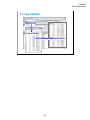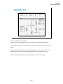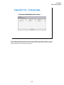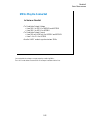
1
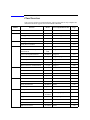
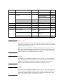
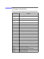
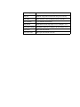
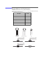
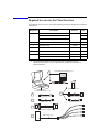
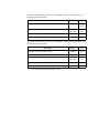
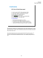
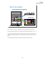
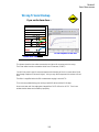
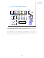
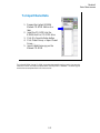
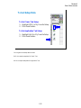
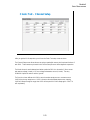
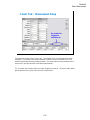
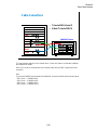
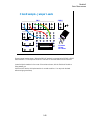
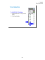
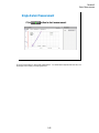
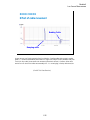
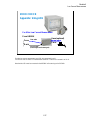
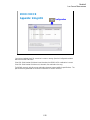
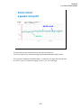
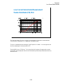
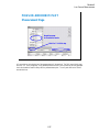
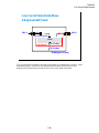
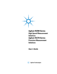
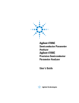
Agilent B1500A
Semiconductor Device
Analyzer
Self-paced Training Manual
Agilent Technologies
Notices
© Agilent Technologies 2005 - 2008
Manual Part Number
No part of this manual may be reproduced
in any form or by any means (including
electronic storage and retrieval or translation into a foreign language) without prior
agreement and written consent from Agilent Technologies, Inc. as governed by
United States and international copyright
laws.
B1500-90042
Edition
Edition 1, September 2005
Edition 2, May 2006
Edition 3, January 2007
Edition 4, June 2007
Edition 5, February 2008
Edition 6, October 2008
Agilent Technologies
5301 Stevens Creek Blvd
Santa Clara, CA 95051 USA
Warranty
The material contained in this document is provided “as is,” and is subject to being changed, without notice,
in future editions. Further, to the maximum extent permitted by applicable
law, Agilent disclaims all warranties,
either express or implied, with regard
to this manual and any information
contained herein, including but not
limited to the implied warranties of
merchantability and fitness for a particular purpose. Agilent shall not be
liable for errors or for incidental or
consequential damages in connection
with the furnishing, use, or performance of this document or of any
information contained herein. Should
Agilent and the user have a separate
written agreement with warranty
terms covering the material in this
document that conflict with these
terms, the warranty terms in the separate agreement shall control.
Technology Licenses
The hardware and/or software described in
this document are furnished under a
license and may be used or copied only in
accordance with the terms of such license.
Restricted Rights Legend
If software is for use in the performance of
a U.S. Government prime contract or subcontract, Software is delivered and
licensed as “Commercial computer soft-
ware” as defined in DFAR 252.227-7014
(June 1995), or as a “commercial item” as
defined in FAR 2.101(a) or as “Restricted
computer software” as defined in FAR
52.227-19 (June 1987) or any equivalent
agency regulation or contract clause. Use,
duplication or disclosure of Software is
subject to Agilent Technologies’ standard
commercial license terms, and non-DOD
Departments and Agencies of the U.S. Government will receive no greater than
Restricted Rights as defined in FAR
52.227-19(c)(1-2) (June 1987). U.S. Government users will receive no greater than
Limited Rights as defined in FAR 52.227-14
(June 1987) or DFAR 252.227-7015 (b)(2)
(November 1995), as applicable in any
technical data.
In This Manual
This document is the self-paced training manual to help you to understand what is Agilent
B1500A, what functions the B1500A has, how to use the B1500A, and what applications
the B1500A contributes to.
CAUTION
The test setup data described in this manual are only examples. If these example data
damage your devices, Agilent is NOT LIABLE for the damage.
•
Module 1. Introduction
This module explains the product concept and the key features of the B1500A/
EasyEXPERT. You will learn about what is the B1500A.
•
Module 2. Getting Started
This module explains the basic operations of the B1500A. You will learn about how to
launch B1500A/EasyEXPERT and how to perform application test and quick test.
•
Module 3. Data Display and Management
This module explains the data display and analysis capabilities of the EasyEXPERT
software. You will learn how to use analysis tools, how to change display setup, and
how to print/export test result data.
•
Module 4. Classic Test Environment
This module explains the classic test mode of the EasyEXPERT. You will learn how to
create the classic test setup in the course exercises.
•
Module 5. Basic Measurement
This module explains the basic I-V sweep measurement function and the cabling and
fixturing issues. You will learn how to measure I-V curves in the course exercises.
•
Module 6. Low Current Measurement
This module explains the low current measurement technique. You will learn how to
measure the low current in the course exercises.
•
Module 7. Measurement Functions
This module explains the measurement functions available with the B1500A. You will
learn how to use various measurement functions in the course exercises.
•
Module 8. Capacitance Measurement
This module explains the capacitance measurement function. You will learn how to
measure the capacitance in a course exercise.
•
Module 9. Modifying Application Test Definitions
This module explains a modification example of an application test definition. You will
learn how to modify the definition in a course exercise.
•
Module 10. Creating Your Test Definitions
This module explains about the application test definition. You will learn how to create
your application test definition in a course exercise.
•
Module 11. Advanced Definitions and Operations
This module explains how to control external GPIB devices, how to call an execution
file, how to perform a repeat measurement, and how to use the prober control script.
•
Module 12. Miscellaneous Operations
This module explains what is the status indicator, what is the automatic data export
function and the automatic data record function, how to perform selftest and
calibration, how to perform SMU zero offset cancel, and such.
•
Module 13. SPGU Control and Applications
This module explains the SPGU Control classic test. You will learn how to create the
classic test setup and the applications using SPGU in the course exercises.
EasyEXPERT is a trademark of Agilent Technologies. All other trademarks are the
property of their respective owners.
Class Exercises
Class exercises use the test setup listed below. The test setup data are only examples and
included in the Demo.xpg file stored in the Manual CD-ROM.
Module
Exercise
Device
Test setup/definition/data
Page
Module 1
no exercise
Module 2
Id-Vd measurement
MOSFET
CMOS: Id-Vd
2-19, 27
Id-Vg, gm-Vg measurement
MOSFET
CMOS: Vth gmMax
2-19, 27
B2200/E5250 switch control
-
Id-Vg, gm-Vg measurement
MOSFET
Module 3
Using Preview window
Module 4
3-28
-
3-31
Trng Id-Vd
4-25
Multi Channel I/V Sweep
Measurement
Bipolar Tr
LED
Trng Multi
4-37
I/V List Sweep Measurement
MOSFET
Trng List
4-51
I/V-t sampling measurement
0.1 μF
Trng Sampling
4-64
Trng CV
4-76
Trng Switch
4-81
Trng C-f
4-88
Direct Control (C-f measurement)
MOSFET
0.1 μF
Id-Vd measurement
MOSFET
IDVD, Id-Vd
5-7
SMU series connection
511 kohm
IRVR
5-24
Parallel
5-28
REKELV
5-38
SMU parallel connection
Re measurement, kelvin connection
Module 7
GMMAX.xtr
MOSFET
B2200/E5250 switch control
Module 6
2-32
Id-Vd measurement
C-V sweep measurement
Module 5
-
-
1 ohm
Bipolar Tr
Leak current measurement
-
Zero-check
6-9
Ultra low current measurement
-
Zero-check-ASU
6-19
Id-Vg measurement
MOSFET
IDVG
6-20
Gummel plot
Bipolar Tr
GUMMEL
6-25
SMU pulse mode
MOSFET
IDVD-Pulse
7-8
RC measurement
0.1 μF and
511 kohm
RC-sampling-log
7-16
Negative hold time
511 kohm
R-sampl-neg-hold
7-22
Auto analysis
MOSFET
GMMAX
7-28
Bias hold function
LED
LED
7-35
SMU series resistor
511 kohm
IV-res
7-43
Module
Exercise
Device
Test setup/definition/data
Page
Module 8
C-V sweep measurement
MOSFET
CV-1MHz
8-6
Module 9
Modifying application test
definition
MOSFET
Trng IdVd Vth.xtd
9-14
Trng idvd idvg2.xtd
9-29
Trng idvd idvg3.xtd
9-32
Using auto analysys twice
MOSFET
Vth gmMax and Id
9-34
Using vector data
MOSFET
Trng Cgg-Vg
9-42
Module 10
Creating application test definition
MOSFET
Trng idvd idvg.xtd
10-17
Module 11
no exercise
Module 12
no exercise
Module 13
Charge pumping
MOSFET
Charge Pumping 4T 0.1V
step
13-20
Flash memory
MOSFET
Demo-S-NorFlash
Endurance
13-29
ALWG output
511 kohm
ALWG monitor
13-36
NOTE
Demo.xpg file
Demo.xpg file is required to create the Demo preset group which contains the test setup
data used by the class exercises. And it is stored in the \data folder on the Agilent B1500A
Manual CD-ROM, Edition 4 or later.
The Demo preset group should be created before starting the class exercise. To create the
preset group, launch EasyEXPERT and import the file by using the Preset Group Import
dialog box opened by clicking My Favorite Setup > Preset Group > Import Preset Group.
The test setup data are only examples for the class exercises.
NOTE
.xtd files
The \data folder on the Manual CD-ROM stores some .xtd files. They are the application
test definitions used by some class exercises. To use the definition file, import the file by
using the Test Definition Import dialog box opened by clicking Library > Import Test
Definition. The test definition data are only examples for the class exercises.
NOTE
.xtr files
The \data folder on the Manual CD-ROM stores some .xtr files. They are the sample test
results created by executing the test setup which has the same name as the result data. To
display these sample test results, import the files by using the Test Result Import dialog
box opened by clicking Results > Transport Data > Import.
Test Setup for Class Exercises
The Demo preset group contains the following test setup. The setup data are only examples
for the class exercises. The following table lists the test setup name in alphabetical order.
Test Setup Name
Description
ALWG monitor
511 kohm sampling measurement with SPGU ALWG output
Charge Pumping 4T
0.1V step
MOSFET Icp-Vbase measurement
CV-1MHz
MOSFET Cgs-Vg measurement
Demo-S-NorFlash
Endurance
MOSFET Endurance test
Fowler-Nordheim
Fowler-Nordheim (FN) plot
GMMAX
MOSFET sqrt_Id-Vg, PEAK-Vg measurement
GUMMEL
Bipolar transistor gummel plot
IDVD
MOSFET Id-Vd measurement
IDVD-Pulse
MOSFET pulsed Id-Vd measurement
Id-Vd
MOSFET Id-Vd measurement, Application Test
IDVG
MOSFET Id-Vg measurement
IRVR
511 kohm I-V measurement
IV-res
511 kohm I-V measurement with SMU series resistor
LED
LED I-V measurement
Parallel
1 ohm I-V measurement, voltage force and current measurement
PG monitor
511 kohm sampling measurement with SPGU VPULSE output
RC-sampling-log
RC sampling measurement, log sampling
REKELV
Bipolar transistor Re measurement
R-sampl-neg-hold
511 kohm sampling measurement with negative hold time
Subthreshold
MOSFET subthreshold measurement
Trng C-f
Direct Control (C-f measurement)
Trng Cgg-Vg
Cgg-Vg modification example for multi-frequency
Trng CV
MOSFET C-V measurement
Trng Id-Vd
MOSFET Id-Vd measurement
Test Setup Name
Description
Trng List
MOSFET Vth-gmmax measurement using I/V List Sweep
Trng Multi
Multi Channel I/V Sweep (Bipolar transistor and LED)
Trng Sampling
0.1 μF sampling measurement
Trng Switch
B2200/E5250 switch setup, Input 1-3-5-7 to Output 1-3-5-7
Vth gmMax and Id
Vth gmMax modification example to use auto analysis twice
Zero-check
SMU open measurement
Zero-check-ASU
SMU open measurement with ASU
Required Devices for Class Exercises
To perform the class exercises, you need the device set (Agilent part number 04156-87001)
which contains the following devices.
Description
Quantity
N-channel MOSFET
2 ea.
NPN Bipolar Transistor
1 ea.
Red Miniature LED
1 ea.
0.1 μF Capacitor 50 V
1 ea.
1.0 Ω Resistor 1/8 W
1 ea.
1.1 kΩ Resistor 1/8 W
1 ea.
511 kΩ Resistor 1/8 W
1 ea.
N-ch MOSFET
NPN bipolar Transistor
LED
Brown
Black
Black
Silver
1 ohm Resistor
Brown
Brown
Black
Brown
1.1 kohm Resistor
Green
Brown
Brown
Orange
511 kohm Resistor
0.1 uF Capacitor
Required Accessories for Class Exercises
To perform the class exercises, you need the following accessories. Prepare the accessories
shown below.
Designation
1
Description
Test Fixture
Model No.
Qty.
16442A/B a
1 ea.
28 pin socket module
1 ea.
Connection wire
6 ea.
2
Triaxial Cable
16494A
4 ea.
3
Interlock Cable
16493J
1 ea.
4
Kelvin Triaxial Cable, for Module 5
16493K
1 ea.
5
CMU Cable, for Module 8
N1300A
1 ea.
6
Atto Sense/Switch Unit, for Module 6
E5288A
1 ea.
ASU control cable, triax cable, for Module 6
16493M
1 ea.
a. The 16058A Test Fixture for the 4145A/B may be substituted for the
16442A/B Test Fixture. If you use the 16058A, you also need the 16435A
Interlock Adapter.
28 pin DIP Socket Module (1ea.)
1
Connection Wire (6ea.)
E5288A ASU (1ea.)
16442A/B Test Fixture (1ea.)
6
2
Triaxial Cable (4ea.)
Control Cable (1ea.)
3
INTLK Cable (1ea.)
4
Kelvin Triaxial Cable (1ea.)
5
CMU Cable (1ea.)
Triaxial Cable (1ea.)
To perform the flash memory class exercise in Module 13 and if you use the ASU, you
need the following accessories.
Description
Model No.
Qty.
E5288A
Total
3sets
16494A or
equivalent
Total
7ea.
BNC-SMA Cable
16493P
3 ea.
SMA-SMA Cable, for synchronization of SPGU
16493Q
2 ea.
ASU (Atto Sense/Switch Unit) with control cable
Triaxial Cable
To perform the flash memory class exercise in Module 13 and if you use the selector, you
need the following accessories.
Description
Model No.
Qty.
SMU/PG selector with control cable a
16440A
2 sets
Selector adapter with control cable
16445A
1 set
16494A or
equivalent
Total
7ea.
BNC-SMA Cable
16493P
3 ea.
SMA-SMA Cable, for synchronization of SPGU
16493Q
2 ea.
Triaxial Cable
a. One selector can be replaced with one ASU.
Contents
Module 1. Introduction
•
New Features
•
EasyEXPERT
•
To Perform Easy Application Test
•
User Interface
•
Modular Mainframe
•
SCUU/GSWU
•
ASU
•
SMU/Pulse Generator Selector
•
B2200/E5250 Switch Control
•
Desktop EasyEXPERT
Module 2. Getting Started
•
To Turn on/off B1500A
•
To Launch EasyEXPERT
•
To Specify/Create Workspace
•
To Perform Application Test
•
To Save/Recall Your Test Setup
•
To Export/Import Your Preset Group
•
To Export/Import Test Record
•
To Perform Quick Test
•
To Control Switching Matrix
•
To Manage Data Display Window
Contents-1
Contents
Module 3. Data Display and Management
•
Data Display window
•
Graph Analysis Tools
•
Data Status
•
To Change Graph/List/Display Setup
•
To See Print Preview
•
To Print Display Data
•
To Copy Graph Plot/List Data
•
To Save Analysis Result
•
To Use Preview Window
Module 4. Classic Test Environment
•
Classic Test Execution Mode
•
I/V Sweep Measurement
•
Multi Channel I/V Sweep Measurement
•
I/V List Sweep Measurement
•
I/V-t Sampling Measurement
•
C-V Sweep Measurement
•
Switching Matrix Control
•
Direct Control
Contents-2
Contents
Module 5. Basic Measurement
•
SMU Fundamentals
•
Classic Test Environment
•
SMUs Connected in Series or Parallel
•
Cabling and Fixture Issues
•
Kelvin and Driven Guard
•
Probes and Prober Connections
•
Triax and Coax Adapters
•
Safety Interlock Issues
Module 6. Low Current Measurement
•
Low-Current Measurement Challenges
•
Calibration and Zero Cancel
•
Effect of Cable Movement
•
ASU for Ultra Low-Current Measurement
•
Low-Current Subthreshold
•
Trade-Off Speed Vs Accuracy
•
Low-Current Gummel Plot
•
Low-Current Gate Oxide Leakage
Contents-3
Contents
Module 7. Measurement Functions
•
SMU Pulsed Sweep Measurement
•
I/V-t Sampling Measurement
•
Negative Hold Time for High Speed Sampling
•
Auto Analysis
•
SMU Filter
•
SMU Series Resistor
•
Standby Function
•
Bias Hold Function
Module 8. Capacitance Measurement
•
CMU Fundamentals
•
Classic Test Environment
•
CMU Calibration
•
SCUU for IV/CV Switching
•
GSWU for Accurate Capacitance Measurement
•
ASU for IV/CV Switching
Contents-4
Contents
Module 9. Modifying Application Test Definitions
•
To Open Application Test Definition
•
To Modify Test Definition
•
To Use Debug Tools
•
To Use Built-in Functions
•
To Add Data Display
•
To Use Auto Analysis
•
To Use Test Setup Internal Variables
•
To Use Auto Analysis twice (as Class Exercise)
•
To Use Vector Data (as Class Exercise)
Module 10. Creating Your Test Definitions
•
What is Test Definition
•
What is Test Contents
•
To Open Test Definition Editor
•
To Define Test Specification
•
To Define Test Contents
•
Available Elements
•
Available Variables
•
To Define Test Output
Contents-5
Contents
Module 11. Advanced Definitions and Operations
•
To Control External GPIB Devices
•
To Call Execution Files
•
To Perform Repeat Measurements
•
Prober Control Script
Module 12. Miscellaneous Operations
•
Function Status Indicator
•
Run Option
•
Automatic Data Export and Data Record
•
Calibration
•
Configuration
•
XSLT Samples
•
To Enable System Controller
•
To Start Desktop EasyEXPERT
•
To Use 415x Setup File Converter
Contents-6
Contents
Module 13. SPGU Control and Applications
•
High Voltage SPGU
•
SPGU Control
•
Pulse Generator Mode
•
Charge Pumping
•
Flash Memory Test
•
ALWG Mode
Contents-7
Contents
Contents-8
5
Basic Measurement
Module 5
Basic Measurement
In This Module
•
SMU Fundamentals
•
Classic Test Environment
•
SMUs Connected in Series or Parallel
•
Cabling and Fixture Issues
•
Kelvin and Driven Guard
•
Probes and Prober Connections
•
Triax and Coax Adapters
•
Safety Interlock Issues
5-2
Module 5
Basic Measurement
SMU Block Diagram
Three Modes
A
V Source Mode
Output Switch
Common Mode
SMU
FORCE
I Source Mode
COMMON
- V +
The source monitor unit (SMU) can function in three modes:
- Voltage source while monitoring current
- Current source while monitoring voltage
- Source common with no monitor
The SMUs on the B1500A can output V or I in constant, linear sweep, logarithmic sweep or pulsed
modes.
Constant V or I mode could be used for “spot” measurements or biases.
Swept output is used to trace a curve. A second SMU can be swept subordinately to measure a
“family of curves.”
Pulsed mode is used during swept measurements to reduce the effects of thermal stress on the device
under test (DUT).
5-3
Module 5
Basic Measurement
Basic Sweep Measurement
VAR1
Single Sweep
Double Sweep
Linear Sweep
Log Sweep
The SMUs can now sweep up to a value and then back down (double sweep). This feature is useful
when the device must be tested without abruptly removing the forcing condition.
Log sweeps are required any time the measurement results span many decades, such as a MOS
subthreshold curve.
The variable used to set the SMU to a basic sweep is VAR1. It may be called the primary sweep.
5-4
Module 5
Basic Measurement
Sweep Measurement Modes
Combining VAR1, VAR1’, VAR2
VAR1
(primary sweep)
Subordinate
sweep
Synchronous
sweep
VAR2
(secondary sweep)
VAR1 (primary sweep)
VAR1’ (synchronous sweep)
A subordinate sweep variable (VAR2) may be combined with the basic sweep variable (VAR1).
This corresponds to the step knob and sweep knob of a curve tracer. This produces a family of
curves. VAR2 may be called the secondary sweep.
Another useful combination is a synchronous sweep. Here VAR1 and VAR1’ are in-step. VAR1’
defaults to a gain of 1, which means it exactly tracks VAR1. You can also vary the initial offset
between VAR1 and VAR1’. These features are useful for bipolar gummel plots, op-amp differential
input tests, etc.
5-5
Module 5
Basic Measurement
Why Four SMUs?
z
z
z
Four terminal MOS device
Only one configuration required
Speed up testing
Drain
Gate
Substrate
Source
VAR1
SMU3
Common
Constant
SMU1
SMU2
VAR2
SMU4
The basic semiconductor device is the 4-terminal MOS transistor. By assigning an SMU to each
terminal, you have complete flexibility to make any measurement without having to change the
device hookup. No relays are required to switch any connection; this is all done by changing the
mode of the SMU from the front panel.
5-6
Module 5
Basic Measurement
Class Exercise
MOS Id vs Vd Basic Measurement
z
z
z
z
z
z
You will connect the SMU cables and jumper leads
You will then "properly" insert the MOS transistor
You will learn how to load a setup data
Observe Classic Test setup screen
Click
button to make a new measurement
Observe Application Test setup screen
To Get Started:
z
z
z
z
Use the next several pages as you guide
Verify that four triax cables are connected as shown
Connect four jumper leads to the 28 pin socket as shown
Insert the MOS transistor using the "anti-static" procedure
The purpose of this class exercise is to familiarize yourself with how to connect a MOS FET device,
and make a basic IDVD family of curves measurement. You will observe the Application Test setup
screen and the Classic Test setup screen (interrelationship between the Channel Setup, Measurement
Setup, Display Setup screen).
The next several pages show how to connect the 4-terminal MOS FET used in this course. The
device for this exercise includes a separate substrate pin. This corresponds to the back gate
connection. We can observe all characteristics of the device as if we were probing it at the wafer
level.
5-7
Module 5
Basic Measurement
SMU Triax Connection
Force Lines to Fixture 1,2,3,4 Ports
Force side
Sense side
CMU
16442A/B Fixture
SMU4
SMU3
SMU2
SMU1
GNDU
B1500A Rear View
For the non-Kelvin connections, connect only the Force lines, leaving the Sense lines open.
Connect corresponding numbers. On the 16442A/B fixture use the numbers labeled 1 - 6, not 1 - 3.
Your B1500A may not match the SMU configuration shown in this figure. Note that SMU1 is the
module top of the GNDU (ground unit). The SMU number become large from bottom to top as
shown.
This is the SMU cable setup that will be used in the remainder of the class exercises.
5-8
Module 5
Basic Measurement
Wrong Triaxial Hookup
If you use the Sense lines …
CMU
SMU4
SMU3
SMU2
SMU1
GNDU
Curves clamped at 10 mA level
B1500A Rear View
This picture shows the triax cables connected to the right set of connectors which is wrong.
The 4 triax cables must be connected to the left set of connectors (FORCE).
You will likely see this type of erroneous response with clamping at 10 mA (no trace above 10 mA
even though compliance is set much higher). Also you may see the response with notches at 10 mA
level.
The effect is magnified when the SMU measurement ranging is set to AUTO.
This curve was produced using your training class MOS device and the IDVD setup.
No error was seen until the ranging was changed from FIXED 100 mA to AUTO. Then it was
evident that the cables were hooked up improperly.
5-9
Module 5
Basic Measurement
Jumper Leads – MOS transistor
F
1
G
F
F
2
1
1
PGU
F
VSU
VMU
SMU
F
4
G
G
G
1
F
3
F
5
F
G
GNDU
6
F
S
G
2
2
2
4
5
6
9
10
11
12
14
15
16
17
18
20
21
22
23
24
1
2
7
8
13
19
28
3
15
25
26
27
28
14
1
S
D
G
Sub
1: Substrate
2: Source
3: Gate
4: Drain
For all class exercises, you need the 28-pin dual in line socket which comes standard with the 4145
fixture (16058A) or the newer fixture (16442A/B). Either fixture works fine.
With the 16442A/B fixture, note that there are two SMU numbering schemes....3 SMUs with force
and sense, or six SMUs with force only. For this class example we will use the six (6) SMU scheme.
On older fixtures, this scheme is shown in light blue lettering. In newer fixtures, this scheme is
shown in white reverse background lettering.
5-10
Module 5
Basic Measurement
To Import Demo Data
1. Prepare the Agilent B1500A
Manual CD-ROM Edition 4 or
later
2. Insert the CD-ROM into the
B1500A built-in CD-ROM drive
3. Click My Favorite Setup button
4. Click Preset Group > Import Preset
Group …
5. Import \data\Demo.xpg on the
Manual CD-ROM
The Agilent B1500A Manual CD-ROM stores demo data used for performing this class exercise.
Insert the CD-ROM and import the demo data to the EasyEXPERT database. The demo.xpg file
contains the test setup data used in this class exercise.
5-11
Module 5
Basic Measurement
To Get Setup Data
To Get Classic Test Setup:
1. Highlight IDVD in My Favorite Setup
2. Click Recall button
To Get Application Test Setup:
1. Highlight Id-Vd in My Favorite Setup
2. Click Recall button
You can get the test setup data as shown.
IDVD is a sample setup data for Classic Test.
Id-Vd is a sample setup data for Application Test.
5-12
Module 5
Basic Measurement
Classic Test – Channel Setup
After you get the IDVD setup data, you will see the Classic Test setup screen as shown.
The Channel Setup screen allows the user to assign a meaningful name to the force/meas functions of
each SMU. These names may be used in the Function Setup screen to define algebraic expressions.
The Mode column is used to determine whether a particular SMU is to be used to 1) force current
and measure voltage (I mode), or 2) force voltage and measure current (V mode). The entry
COMMON implies the node is used as "ground."
The Function column defines which SMUs are to be used as swept sources or constant sources.
VAR1 is the primary swept source. VAR2 is known as the subordinate swept source, meaning
VAR1 will sweep through its range, then VAR2 will step and VAR1 will sweep again. CONST is
self- explanatory.
5-13
Module 5
Basic Measurement
Classic Test – Measurement Setup
Do not abort on
compliance,
oscillation, etc.
The Measurement Setup screen is shown here. The variables VAR1 and VAR2 define the sweep
parameters. In a case where two sweep parameters are defined, the second parameter (VAR2) is
called the subordinate (secondary) sweep parameter. This means that the primary parameter will be
swept once for each discrete value of the subordinate parameter.
The “Constants” area is used to define non-swept voltage/current sources. This area is used to define
ground references (forcing zero volts) as well as constant biases.
5-14
Module 5
Basic Measurement
Classic Test – Display Setup
The Display Setup screen allows you to set the X-Y graph axes. The display setup is divorced from
the measurement setup to allow the user to tailor the view to a particular region of interest.
This screen also allows you to set data variable names to be displayed in the List Display and
Parameters areas on the Data Display window which is opened when the measurement is started.
5-15
Module 5
Basic Measurement
To Start Measurement
1. Click Single button
This opens the Data Display window
and starts measurement.
The Data Display window shows
measurement result data graph/list.
5-16
Module 5
Basic Measurement
Data Display Window – Graph
Analysis tools
Graph Plot
Parameters
Auto Scale
List Display
This window displays measurement result graph, list, and parameter values.
Markers are used to traverse the actual measurement data. Markers cannot be placed anywhere on
the screen except on an actual measurement trace. They are denoted with a small circle. One moves
the markers with the front panel rotary pulse generator (RPG) knob, mouse, or touch screen.
Cursor may be used anywhere on the screen and are denoted by a small cross. The cursor is moved
using mouse, touch screen, or an arrow key.
The line function may be selected to draw one of four types of lines: line between cursors, gradient
line, tangent line, regression line.
One of the most used interactive functions on this window is the autoscale feature which is applied
by clicking the icon of yardsticks.
5-17
Module 5
Basic Measurement
Data Display Window - List
Analysis tools
Graph Plot
Parameters
Marker position
List Display
The List Display corresponds exactly with the Graph Plot. Even the highlighted line of data
corresponds to the marker position on the Graph Plot.
Up to twenty columns of data can be set on the List Display. Note that the Graph Plot can only plot
nine columns (X, Y1 to Y8).
The list data can be copied to a spreadsheet software easily. Click Edit > Copy List. This copies all
of the list data into the clipboard.
On the Notepad, paste it and save it as a text file. The file can be opened as a tab separated value
data by using a spreadsheet software. See the next page.
The details of the analysis tools function are discussed in Module3.
5-18
Module 5
Basic Measurement
To Copy List Data
Paste to Notepad
Open by a spreadsheet software
5-19
Module 5
Basic Measurement
Application Test
Recall Id-Vd application test setup data.
After you get the Id-Vd setup data, you will see the Application Test setup screen as shown.
Test Parameters area shows the device connection information and allows the user to set the SMU
outputs.
Device Parameters area allows the user to set device parameters. In the Id-Vd setup, the device
parameters are polarity, gate length, gate width, temperature, and maximum drain current.
Extended Setup button opens the Extended Setup dialog box shown in the next page.
5-20
Module 5
Basic Measurement
Application Test – Extended Setup
Clicking the Extended Setup button opens …
The Extended Setup dialog box allows the user to set the additional test setup parameters. In the IdVd setup, the additional parameters are source voltage, maximum gate current, maximum substrate
current, integration time, hold time, and delay time.
5-21
Module 5
Basic Measurement
SMUs May Be Connected
In Series or Parallel
z
z
z
To Double the Output Voltage
z from 100 V to 200 V for HRSMU and MPSMU
z from 200 V to 400 V for HPSMU
To Double the Output Current
z from 100 mA to 200 mA for HRSMU and MPSMU
z from 1 A to 2 A for HPSMU
Use the VAR1’ mode to synchronize two SMUs
You can double the voltage or current output by combining SMUs.
The VAR1’ mode allows a second SMU to be swept in tandem with the first.
5-22
Module 5
Basic Measurement
200 Volt Sweep (400 Volt with 2 HPSMUs)
Two SMUs in Series
Base current = 0
or leave open
WARNING
Collector
V2
V1
Base
Const.
SMU1
I=0
Emitter
VAR1'
VAR1
VAR1
SMU2
V=0 to -100
SMU3
V=0 to 100
200 V BVceo
SMU1
V=0 to 100
VAR1'
SMU2
V=0 to -100
200 V Resistor Sweep
Higher voltages are necessary to observe breakdown conditions, such as BVceo. In the case of
BVceo the base must be open (no SMU) or the SMU must be set as a current source with I=0.
One SMU must sweep in a positive direction while the other sweeps in a negative direction. The
result is a floating measurement with double the differential voltage. A resistor is used in the next
few slides to demonstrate a 200 V sweep.
Note: Using two HPSMUs, it is possible to sweep a total of 400 Volts.
5-23
Module 5
Basic Measurement
Channel and User Function Pages
Two SMUs in Series
Voltage across resistor
VR = V1-V2
The voltage across the resistor (VR) is the difference between V1 and V2. A simple user function
can be used to plot VR.
5-24
Module 5
Basic Measurement
Measurement and Display Pages
Two SMUs in Series
VAR1' Ratio = -1
The VAR1’ mode is used to synchronously sweep two SMUs. Setting Ratio = -1 forces one SMU to
sweep in the opposite direction of the other.
5-25
Module 5
Basic Measurement
Graphics Page
0 to 200 V
Two SMUs in Series
WARNING
Use the interlock
cable and observe
safety precautions.
511K
Resistor
The result is a clean 200 V sweep.
Remember that there is a serious shocking hazard.
The interlock cable is necessary for any voltage sweep greater than 42 V.
5-26
Module 5
Basic Measurement
200 mA Output
Two SMUs in Parallel
V1
V2
1 ohm
VAR1
SMU1
V=0 to 0.2
NOTE
VAR1’
Ground Unit
(GNDU) or
Chassis Gnd
Use Ground Unit
or the chassis
ground as the
SMU return path.
Shorting bar
SMU2
V=0 to 0.2
Circuit Common
Two SMUs can be operated in parallel.
The trick is to not use any SMU as COMMON.
HRSMU and MPSMU can only sink 100 mA.
Use GNDU (ground unit) or the chassis to sink the 200 mA of current. Chassis noise level will not
affect the measurement. There is a shorting bar in the back of the instrument which connects SMU
common to the chassis. The shorting bar must be connected as shown above. Use the connector on
the shorting bar to make an easy chassis connection to your circuit. The chassis connection is also
provided if you use a packaged part test fixture, such as the 16058A or 16442A/B.
Note
The only time you would ever want to remove the shorting bar, is the case of floating the instrument
circuit common when using other instruments. An example might be a connection to a RF Network
Analyzer. You may want to remove chassis ground loops by connecting the circuit common directly
to the NWA chassis.
Note
Never use the chassis ground for low current measurements. It is noisy. Use the GNDU or an SMU
set to 0 volts or COMMON mode.
Note
If the GNDU is used, connect the 16493L GNDU cable between the GNDU and the test fixture. Do
not connect the triaxial cable. The GNDU is rated for up to 4.2 A, while the maximum current rating
of the triaxial cable is 1 A.
5-27
Module 5
Basic Measurement
Channel and User Function Pages
Two SMUs in Parallel
Current in resistor
Itotal = I1+I2
A user function totals the current in both SMUs.
5-28
Module 5
Basic Measurement
Measurement and Display Pages
Two SMUs in Parallel
VAR1' Ratio = 1
The VAR1’ mode with Ratio = 1 forces two SMUs to sweep the same voltage.
5-29
Module 5
Basic Measurement
Graphics Page
0 to 200 mA
Two SMUs in Parallel
1 ohm
Resistor
The result is a clean sweep to 200 mV. It shows the current measurement data near 200 mA.
5-30
Module 5
Basic Measurement
Cabling and Fixturing Issues
z
Guard connection
z
Kelvin connection
z
Prober interface
z
Triaxial Probes
z
RF Fixturing interface
z
Feedthru and triax to coax adapters
z
16442A/B fixture interlock
z
16058A fixture compatibility
What?
Where?
Why?
The B1500A is a precision instrument. However, the ability to make precise and reliable
measurements may be compromised by your fixturing to the device. The following section provides
some theory and hints for making sense out of cabling and fixturing issues.
5-31
Module 5
Basic Measurement
Guard Connection for Non-Kelvin Connection
Simplified Diagram
Buffer
x1
Rs
10K
Guard
SMU
Force
DUT
V
The guard connection is needed for measurement < 1 nA. Below 1 nA a regular coax cable's
capacitance dominates over the DUT (device under test) capacitance. What you see is cable
charging current. I = C(dv/dt) where dv/dt is the rate of change of SMU voltage from one step to the
next of a coax cable with no guard. C is the total capacitance of the cable.
The above diagram shows how the cable capacitance is eliminated with a triaxial cable. The guard is
driven at the same voltage as the force center conductor. No current can flow between guard and
force when they are held at the same potential. Guard and force are isolated by a buffer amplifier.
They can never be shorted together.
5-32
Module 5
Basic Measurement
Triaxial Cable for Non-Kelvin connection
Shield (Ground)
Guard
Force
16494A-001
(1.5 m)
16494A-002
(3.0 m)
Shield Capacitance
900 pF
1800 pF
Guard Capacitance
130 pF
240 pF
Force Resistance
160m ohm
320m ohm
Shown above are typical capacitance and series resistance of the force line. If cables are too long,
high capacitance may cause the SMU to oscillate. Keep the force-guard cable capacitance less than
600 pF. Similarly, the guard-shield capacitance must be less than 5000 pF.
Note the rather high force resistance. Kelvin connections must be used to eliminate this cable error.
5-33
Module 5
Basic Measurement
Why Use Guarded (Triax) Cables?
Shield (Ground)
Guard
Leakage
Shield (Ground)
Force
Force
MOSFET Subthreshold
MOSFET Subthreshold
Id
mA
mA
uA
uA
Id
nA
pA
nA
pA
fA
fA
Vg
Triax Cables
Vg
Coax Cables
Eliminate cable low current errors.
The triax cable is a special low dielectric loss, high impedance cable. This cable may be used down
to fA levels when properly used with a guarded probe. The guard voltage tracks the force voltage
exactly, so that no voltage drop can exist between guard and force. This eliminates the capacitive
loading that would otherwise limit low current measurements.
If low impedance coax cables are used with outer layer at ground potential, two limitations will be
immediately apparent. The cable leakage will limit the low current measurement floor. In addition,
when the voltage is swept, the sudden change will cause additional cable charging. This distorts the
low current portion of a MOS subthreshold curve as shown.
RULES:
Unguarded coax cable is OK for measurements above 1 nA.
Triax cable or coax with outer layer at guard potential should be used for measurements below 1 nA.
5-34
Module 5
Basic Measurement
Guard Connection for Kelvin connection
Simplified Diagram
Buffer
x1
Guard
Rs
10K
Sense
Force
SMU
DUT
V
With the Kelvin connection, sensing is done at the DUT, eliminating the fraction of an ohm of cable
resistance. The internal sensing resistor Rs is the only feedback path without the Kelvin connection.
Note that the B1500A operates just fine without the sense cable. This is important to know because
in general you do not need the sensing Kelvin connection. Most MOS measurements are high
impedance and the residual cable loss is insignificant.
5-35
Module 5
Basic Measurement
Kelvin Triaxial Cable
Ground
Guard
Force
Sense
The triaxial cables are good for low current measurements. However, two cables are necessary for
low resistance Kelvin measurements.
Agilent Technologies designed a special Kelvin triaxial cable for the precision semiconductor
parameter analyzers. This cable is optimized for both low current and low resistance measurement.
Both force and sense lines are held rigidly in the same Teflon cable. Friction is reduced and the
cable is less sensitive to noise caused by moving the cable.
Kelvin triaxial cable assemblies are available with two connector options:
16494B
B1500/4156 compatible on one end; 4142 compatible on the other end
16493K
B1500/4156 compatible on both ends (standard option)
5-36
Module 5
Basic Measurement
Why Kelvin Measurements?
VC
monitor
IB
20
Re = 735 mΩ
Slope = 1/Re
(Kelvin)
Rcable = 214 mΩ
Ib (mA)
Slope = 1/(Re+Rcable)
(Non-Kelvin)
0.1
0
Vc (mV)
50
In the example above, the device is connected with a SMU on the base sweeping current, a voltmeter
on the collector, and the emitter is grounded with a Kelvin SMU. The base SMU does not have to be
Kelvin since we are only forcing current and do not care about measuring the cable loss in the base.
Also, the collector SMU is being used only as a high impedance voltmeter, so there is no cable loss
in this lead.
The emitter on the other hand, must be connected to a Kelvin SMU. Because of this, we can
compensate for the 0.214 ohm path through the cable and fixture. From the graph we can see the
emitter resistance is 0.735 ohm when compensated using the Kelvin connection. Non-Kelvin
resistance is 0.949 ohm, due to the extra 0.214 ohm cable and fixture resistance error.
5-37
Module 5
Basic Measurement
Class Exercise
Bipolar Re Using A Kelvin SMU
z
z
z
z
You will connect a Kelvin triax cable to the B1500A
You will then connect jumper leads and the bipolar device
You will get the REKELV setup
You will observe Re using Kelvin and Non-Kelvin connections.
Why is the Non-Kelvin error so large?
To Get Started:
z
z
z
z
Use the next several pages as you guide
Verify that all triax cables are connected properly
Connect four jumper leads to the 28 pin socket as shown
Insert the bipolar transistor (not static sensitive)
The purpose of this class exercise is to familiarize yourself with making a Kelvin measurement. Low
resistance measurements such as Re, Rc (bipolar) or Rs, Rd (MOS) are excellent examples because
the resistances are of the same approximate magnitude as cable resistances. Kelvin techniques must
be used, or your error can be as much as 100 %.
The next several pages lead you through the steps of connecting a Kelvin cable, making the correct
Force/Sense jumper lead connections, orienting the device properly in the socket, and getting the
REKELV algorithm. The measurement will be Re (emitter resistance) of a bipolar transistor. You
will be able to remove the Sense jumper lead on the Emitter terminal of the device to see the gross
measurement degradation when the connection is non-Kelvin (no sense connection near the device).
5-38
Module 5
Basic Measurement
Cable Connections
z
Triax to SMUs 1 and 2
z
Kelvin Triax to SMU 3
CMU
16442A/B Fixture
SMU4
SMU3
SMU2
SMU1
GNDU
B1500A Rear View
This class example requires a Kelvin triaxial cable. If the Kelvin cable is not available, substitute
two standard triax cables.
SMUs 1,2,3 can all be connected with Kelvin triaxial cables, but only SMU3 requires the Kelvin
connection.
Note
If you use the 16058A fixture instead of the 16442A/B, connect the triaxial cables as shown below.
SMU1 Force ---> 16058A SMU1
SMU2 Force ---> 16058A SMU2
SMU3 Force ---> 16058A SMU3
SMU3 Sense ---> 16058A SMU4
5-39
Module 5
Basic Measurement
Class Example - Jumper Leads
F
1
G
F
F
2
1
PGU
F
VSU
SMU
F
4
G
G
G
1
F
3
F
5
F
G
1
F
S
G
2
2
4
5
6
9
10
11
12
14
15
16
17
18
20
21
22
23
1
2
7
8
13
19
28
3
15
25
VMU
GNDU
6
24
26
EBC
2
27
28
14
1
E
B
C
17: Emitter
16: Base
15: Collector
Connect jumper leads as shown. Where, the SMU4 F terminal is connected to the B1500A’s SMU3
Sense connector. So the couple of the SMU3 F and SMU4 F terminals makes a Kelvin terminal.
Locate the bipolar transistor in the corner of the socket as shown, with the flat side of the device
facing toward you.
Unlike the MOS device, the bipolar transistor is not static sensitive. You may touch the leads
without using a ground strap.
5-40
Module 5
Basic Measurement
To Get Setup Data
To Get REKELV Test Setup:
1. Highlight REKELV in My Favorite
Setup
2. Click Recall button
5-41
Module 5
Basic Measurement
Single Kelvin Measurement
Click
button to start measurement
Click the Single button to make a new measurement. You should see a response similar to this, will
the analysis line correctly overlaying the curve.
5-42
Module 5
Basic Measurement
Non-Kelvin Measurement
Click
button to start append measurement
You can switch
the analysis line
between the two
curves with this
softkey
Remove the jumper lead connected between the terminal 17 and the SMU4 F terminal. And click the
Append button to add another measurement to the graph.
Now you see the very large difference between Kelvin and non-Kelvin measurements when the
resistance is low. You can see that Re jumps from about 0.735 ohm in this example, to about 0.949
ohm. The extra resistance is due to cable loss and fixture loss. This resistance is compensated out
when you use the Kelvin connection.
5-43
Module 5
Basic Measurement
Prober Kelvin Cable Connection
To Kelvin Probe
To Guarded Chuck
Photo of SMU cable connection to a Cascade Microtech Summit probe station.
The Kelvin triaxial cables mate directly to the probe station.
5-44
Module 5
Basic Measurement
Connector Plate
Non-Kelvin Connection
Shielding Box
Kelvin Triaxial Cable
16493K
GUARD Line
FORCE,SENSE Line
COMMON
GUARD
FORCE
Probe Cable (Coaxial)
S
M
U
F
F
S
S
Connector Plate
16495H-002
or
16495J-002
SENSE
GUARD
COMMON
Insulator
Prober
DUT
Jumper to eliminate cable
resistance in force line
This is a "hybrid" Kelvin connection. Cable resistance from SMU is eliminated by shorting FORCE
and SENSE lines inside the prober. A short line to the probe makes the non-Kelvin connection,
simplifying hookup.
5-45
Module 5
Basic Measurement
Simplifying the Prober Connection
z
Use single triax for basic MOS FET measurements
z
One triax on each Force line
z
Leave the Sense lines open...no cable connected
z
Use triax bulkhead feedthru adapters on the prober
z
Use a probe holder with a triaxial connector
z
Use a probe holder than accommodates replaceable
probe tips (inexpensive repair)
The next section sheds light on the confusing topic of connection to the device under test. Without
proper considerations, noise, capacitance, sense resistance, or inductance will result in unacceptable
measurement error.
5-46
Module 5
Basic Measurement
Triaxial Probes
Guarded to within 2mm of tip
Single Triax
Kelvin Triax
These probes are guarded within 2mm of the probe tip, ideal for low current applications. The
Kelvin triax probe is the ideal mate for the Kelvin triax cable. A third variation of these probes is a
Kelvin triax probe with only one probe. The Kelvin connection is made inside the probe holder.
This compromise eliminates most cable loss while making a single point contact.
5-47
Module 5
Basic Measurement
Simplifying RF Connections
z
Triax is not necessary...bias currents are > 1 nA.
Use triax to coax adapters with floating guard.
Bias Network
RF in
Bias
F
DUT
Bias Sensing
SMU1
Bias Network
RF out
Bias Bias Sensing
S
F SMU2
S
Above 1 nA guarding is of little use. Cable capacitance has a negligible effect on the bias port. Use
the floating guard triax(m) to BNC(f) adapter at the B1500A rear panel. Then use standard coax
BNC cables. Use sense to minimize series resistance error. 100 mV errors can occur in bias voltages
if remote sensing is not used.
Some recent bias tees from Agilent Technologies are specially designed to mate easily to triax SMU
ports.
5-48
Module 5
Basic Measurement
Interlock Connection
z
z
For measurements above 42 Volts
For program control using program memory
6 1
2
5
4 3
Short required
View from B1500A rear panel
To prevent shock hazard, the B1500A will not operate above 42 V, unless you connect the interlock
circuit.
The interlock connection is required when the voltage exceeds 42 V or when the program memory is
used in a control program.
The 16442A/B test fixture has the interlock circuit internally which makes this short by closing a lid
activated switch.
You must make the circuit to your prober to comply with US OSHA safety standards. The switch on
the prober should be mounted into the access door of the shield box.
If you want to connect to the BNC type interlock connector on the 16088B, your fixture or prober,
use the 16435A Interlock Cable Adapter. The 16435A provides a BNC cable and a small adapter
box which is used to join the BNC cable and the interlock cable furnished with the B1500A.
If you want to wire your own cable or fixture, these Agilent part numbers may be used:
1252-1419 Female 6-pin plug connector
1252-1418 Male 6-pin cable connector
5-49
Module 5
Basic Measurement
16442A/B Fixture
interlock cable
16493J-001
16493J-002
1.5 m cable
3.0 m cable
The 16493J interlock cable is designed to be connected directly between the B1500A’s interlock
connector and the 16442A/B. If the fixture lid is closed, internal switch is closed, and then the
B1500A can perform measurement up to 100 volts; 200 V with the HPSMU.
5-50
Module 5
Basic Measurement
16058A Fixture Compatibility
Use the 16058A with the B1500A
4 non-Kelvin SMU inputs
3 general purpose coaxial inputs
Add the 16493A Adapter Cable
Interlock connection
4 additional coaxial inputs
Add the 16435A Adapter
The 16058A has 4 non-Kelvin SMU inputs and 3 coaxial inputs for the other instrument connection.
By adding the 16493A Adapter Cable, you get access to 5 more coaxial connections. The adapter
was designed to bring out the fixture interlock connection and 4 additional connections, such as the
4142/4155/4156’s VSU/VMU.
The 16493A cable converts the 16058A fixture interlock connection to a single coaxial connector.
This mates directly with the 16435A Interlock Cable Adapter mentioned on the previous page.
Note
You will notice that the socket modules for Agilent Technologies entire DC parametric product line
are interchangeable. So socket modules that came with the 4142, 4145, 4155, or 4156 will work with
the 16058A, 16088A/B, and 16442A/B fixtures.
5-51
Module 5
Basic Measurement
5-52
6
Low Current Measurement
Module 6
Low Current Measurement
In This Module
•
Low-Current Measurement Challenges
•
Calibration and Zero Cancel
•
Effect of Cable Movement
•
ASU for Ultra Low-Current Measurement
•
Low-Current Subthreshold
•
Trade-Off Speed Vs Accuracy
•
Low-Current Gummel Plot
•
Low-Current Gate Oxide Leakage
This module is primarily written for the B1500A installed with the HRSMU (high resolution SMU)
and covers sub pA measurement techniques. Course exercises are included which fully explore
speed vs. accuracy issues to the fA level.
6-2
Module 6
Low Current Measurement
Low Current Measurement
What is possible?
z
Measurements below 10 fA at the wafer level
z
Repeatability within a few fA
z
Speeds less than 1 minute for subthreshold sweep
Making wafer level measurements to fA levels is easy and routine using proper measurement
procedures on a low noise probe station. This module explains how.
6-3
Module 6
Low Current Measurement
Low Current Measurement
Challenges
z
z
z
z
NOISE FROM PROBER
z Faraday enclosure required
z Eliminate all electrical interference
STRAY CAPACITANCE
z Full guarding, including the probe
z Guarded chuck to measure substrate current
MEASUREMENT SETUP
z Hold time, integration, auto ranging
CALIBRATION & ZERO CANCEL
Measurement below 1pA is not possible without special attention to the prober and cabling. The
wafer must be in total darkness and in an electrically isolated metal box. Motors must be turned off
or completely shielded.
Stray capacitance kills any hope of making good low current measurements. High cable capacitance
which is unguarded can produce pA level currents during voltage steps. The probes themselves must
be guarded.
The B1500A defaults at bootup to setup conditions which are not optimized for ultra low current.
This is desirable because there is a large trade-off between speed and ultra-low current accuracy.
The typical use is moderate current levels where settings can be optimize for speed, not accuracy.
There are some features such as zero cancel, which can eliminate the last 10 or 20 fA of error from
your measurement. Before zeroing, you should check that SMU CALIBRATION has been
performed. SMU Calibration removes most error and makes the final zero cancel easier.
6-4
Module 6
Low Current Measurement
Clean Probing Environment
What is Required?
9 Low loss triaxial connection (no matrix card)
9 Guard to tip of probe (no bare needle or probe cards)
9 No air flowing near probe tip (including dry nitrogen)
9 No hot chuck
9 Chuck isolated from ground (10^13 ohms)
9 Chuck guarded for substrate measurements
9 Shielded probe station
9 No vibration; cables stationary
9 Microscope light, motors, etc. off
This check list covers most sources of noise or stray capacitance. In a "clean" probing environment
the B1500A can be used with short integration time and no delay time between steps.
6-5
Module 6
Low Current Measurement
Debugging A Noisy Probe System
Where to Start?
z
z
Sweep 0 to 1 volt with no cables attached to SMU
z Check that there is a +/- 3 fA base line
Add prober cables but no prober
z Wait several minutes
z Still +/- 3 fA base line?
z
Add shielded prober but no probes
z
Add probes
This is a systematic strategy for focusing in on the sources of noise and error. You can be very
surprised. Some prober cable is not low loss. You may see popping noise due to relaxing of Teflon
fiber in the cables, high current level due to poor dielectric loss, etc. You may find improper triax
adapters, high levels of stray capacitance, etc., as you add prober and probe connections.
6-6
Module 6
Low Current Measurement
Low Current
Calibration & Zero Cancel
z
z
z
WAIT 30 MINUTES AFTER TURN ON
z Instrument must stabilize
CAL & ZERO WITH PROBES UP
z Prevent device damage
ZERO EVERY 30 MINUTES
z To get repeatable fA level measurements
The SMU can be thought of as a sophisticated OP AMP. With any OP AMP there is an associated
input offset error. This error is small and varies with ambient temperature shifts and other factors. It
can be reduced to a negligible amount with a zero cancel function.
Zeroing is performed with the probes up. If there is a very large error to correct, you may get a
warning message. This usually means that SMU CALIBRATION has not been recently performed.
SMU calibration eliminates gross. ZEROing only has an effect on the 1 nA range or less.
Use the Calibration window to perform the SMU calibration and zero cancel. See the next page.
NOTE:
The B1500A provides the auto calibration function which automatically starts calibration for all
modules every 30 minutes if the output switches of all modules are off for 30 minutes. You can
enable or disable this function on the Calibration window. If auto-calibration is enabled, move
probes up (open measurement terminals) after measurement to prevent device damage and to
perform calibration correctly.
6-7
Module 6
Low Current Measurement
Low Current
Calibration & Zero Cancel
Calibration
Click Calibration button to open the Calibration window.
SMU calibration is performed on the SMU Calibration tab screen. Specify the modules for
calibration by checking the left check box and click Start Calibration button to start calibration. If
ASU (atto sense/switch unit) is connected and 1 pA range is used for measurement, check Full Range
Calibration check box before clicking Start Calibration button.
SMU zero cancel is performed on the SMU Zero Cancel tab screen. Specify the modules for zero by
checking the left check box and click Measure... button to start SMU zero. If ASU is connected and
1 pA range is used for measurement, check Full Range check box before clicking Measure... button.
To enable the auto calibration function, check the Enable Auto Calibration check box on the SMU
Calibration tab screen.
6-8
Module 6
Low Current Measurement
Class Exercise
Measurements Near Zero fA
You will be able to answer the following questions:
z
What does a sweep into an open SMU port look like?
z
What is the time per meas using PLC integration?
z
Add a 1.5 m cable during a sweep...how long to settle?
z
Move and bend the cable...how much current flows?
To Get Started:
z
Use the next several pages as your guide
z
Remove any cable attached to SMU4
z
Measure SMU4 noise level using the setup shown
The following pages lead you step-by-step through the "ZERO CHECK" class exercise. This is the
logical place to start if you are debugging a "noisy" test environment.
You will create an algorithm to look at the low level measurement capability of a SMU. On the next
page you will see the expected curve when looking into an open at the rear panel.
6-9
Module 6
Low Current Measurement
ZERO CHECK - No cable
Using Default SMU Setup
Cursor at the maximum point 3.17 fA
Marker at the minimum point -1.84 fA
+/- 3 fA variation typical, using 16 PLC integration time
With slight modification of the default SMU settings of Classic Test I/V Sweep, you can check the
conditions of your measurement system. This is a typical plot when no cable is attached to the SMU
port. You would typically expect no more than a few fAs of deviation from zero using 16 PLC
integration time.
6-10
Module 6
Low Current Measurement
ZERO CHECK
Channel Setup
Change Mode to V and
Function to VAR1
Delete SMU1 and SMU2
Click the Classic Test tab, I/V Sweep, and Select to display the Channel Setup screen.
On this display, delete the rows of SMU1 and SMU2.
Change the Mode of SMU4 to V.
Change the Function of SMU4 to VAR1.
This setup will be used for checking the zero measurement on SMU4.
6-11
Module 6
Low Current Measurement
ZERO CHECK
Measurement Setup
Do not change this screen
This default sweep setup is enough for the Zero Check measurement.
The sweep steps are small (10 mV) and that is ideal for checking current at fA levels.
Also the sweep starts at 0, so no big discontinuities on the first step of the sweep.
There is no need to change anything on the Measurement Setup screen. But the ranging mode and
the integration time settings must be changed. See the next page.
Click Range button to change the ranging mode.
Click ADC/Integ button to change the integration time setting.
6-12
Module 6
Low Current Measurement
ZERO CHECK
Range and Integration Time
Change SMU Range to
AUTO or LIMITED 10 pA
Change Integration Time to
16 PLC
You must change the range setting from the default of LIMITED 1 nA to LIMITED 10 pA or to
AUTO. Otherwise you will have 100 fA resolution instead of the best 1 fA resolution possible.
Also change the High Resolution ADC Mode to PLC and Factor to 16. You will see +/- 3 fA
variation measurement result as shown in the previous slide.
6-13
Module 6
Low Current Measurement
ZERO CHECK
Display Setup
Linear, with zero set to mid scale
The best check is done with a LINEAR scale which brackets either side of ZERO by 100 fA or less.
A log scale is particularly unacceptable, Log plots of zero are not possible, and all readings of a log
plot must be either all positive or all negative.
6-14
Module 6
Low Current Measurement
ZERO CHECK
Effect of connecting a triaxial cable
Approx. 50 sec
> +/- 3 fA
< +/- 3 fA
< +/- 3 fA
If you change anything in your fixturing or cabling, wait at least 1 minute before making a
measurement at low currents.
Here we see the effect of connecting a cable to the open SMU port of the B1500A. The discontinuity
lasted for 50 seconds of a 2 minute sweep from 0 to 1 volt in 10 mV steps.
6-15
Module 6
Low Current Measurement
ZERO CHECK
Effect of cable movement
Bending Cable
Bumping cable
As you can see, your fixturing must be free from vibration. Bending cables during a test is another
NO NO. The above measurements were made on a single triax cable for classic parameter analyzers.
The Kelvin triax cable is less sensitive to movement (triboelectric effects). However, either cable
works fine to fA level if the cables are reasonably still...i.e. not swinging, coiled up and moved, etc.
(End Of This Class Exercise)
6-16
Module 6
Low Current Measurement
ZERO CHECK
Appendix: Using ASU
For Ultra Low Current Measurement
From HRSMU
Force
D-sub
Sense (optional)
Triax cable
Force
Control cable
(control signal and Sense signal)
For ultra low current measurement, use ASU (atto sense/switch unit).
The HRSMU has an innate 1 fA measurement resolution. And the ASU extends it to 0.1 fA.
Note that the ASU must be connected to the HRSMU before turning on the B1500A.
6-17
Module 6
Low Current Measurement
ZERO CHECK
Appendix: Using ASU
Configuration
You can check whether the ASU connection is correct or wrong. Open the Configuration window
and look at the ASU tab screen.
If the ASU Serial Number field shows its serial number, the HRSMU-ASU combination is correct.
If the ASU Serial Number field shows *s/n mismatch, the combination is wrong.
The B1500A can work with this wrong combination however it cannot satisfy its specifications. The
specifications are guaranteed for the correct combination of HRSMU and ASU.
6-18
Module 6
Low Current Measurement
ZERO CHECK
Appendix: Using ASU
HRSMU+ASU
HRSMU
This slide shows the open measurement results with ASU and without ASU.
The ASU provides the 1 pA measurement range and the stable measurement results as shown.
The 1 pA range is disabled with the default setting. To enable the 1 pA range, set the ranging mode
to LIMITED 1 pA (1 pA limited auto ranging) or FIXED 1 pA (1 pA fixed range).
6-19
Module 6
Low Current Measurement
Class Exercise
Low Current Subthreshold
You will:
z Check low level accuracy with fixture lid open/closed
z Observe trade off between resolution and speed
z Change resolution from LIMITED 1 nA to LIMITED 10 pA
z Observe trade off between averaging and speed
z Change integration from AUTO to PLC to MANUAL
To Get Started:
z
z
Use the next pages to setup the MOS FET correctly
Get the IDVG setup in the Demo preset group
The following pages show a typical plot of the subthreshold curves for this class exercise, device
connections, and setup changes with comments.
6-20
Module 6
Low Current Measurement
Jumper Leads – MOS transistor
F
1
G
F
F
2
1
1
PGU
F
VSU
VMU
SMU
F
4
G
G
G
1
F
3
F
5
F
G
GNDU
6
F
S
G
2
2
2
4
5
6
9
10
11
12
14
15
16
17
18
20
21
22
23
24
1
2
7
8
13
19
28
3
15
25
26
27
28
14
1
S
D
G
Sub
1: Substrate
2: Source
3: Gate
4: Drain
For all class exercises, you need the 28-pin dual in line socket which comes standard with the 4145
fixture (16058A) or the newer fixture (16442A/B). Either fixture works fine.
With the 16442A/B fixture, note that there are two SMU numbering schemes....3 SMUs with force
and sense, or six SMUs with force only. For this class example we will use the six (6) SMU scheme.
On older fixtures, this scheme is shown in light blue lettering. In newer fixtures, this scheme is
shown in white reverse background lettering.
Connect the cables between the B1500A and test fixture as follows.
SMU1 : SMU1
SMU2 : SMU2
SMU3 : SMU3
SMU4 : SMU4
Connect jumper leads as follows.
Terminal 1 : SMU1 F terminal
Terminal 2 : SMU2 F terminal
Terminal 3 : SMU3 F terminal
Terminal 4 : SMU4 F terminal
6-21
Module 6
Low Current Measurement
Class Exercise
SD214DE MOS Subthreshold
With lid closed, you should see this typical response using the IDVG setup data. If the subthreshold
region is much higher, at the pA or nA level, the MOS device may be statically damaged. Replace
the device using the handling procedure detailed on the previous page.
6-22
Module 6
Low Current Measurement
Class Exercise
Trade Off Speed vs Accuracy
Change LIMITED range
from 10 pA to 100 nA.
Change Factor from 16 to 1.
Change Mode from PLC to AUTO
to NORMAL.
You can trade off speed vs accuracy by varying the LIMITED range setting or the integration time
setting.
The 100 nA range will speed up the test but you will lose low-end resolution. Try setting LIMITED
to 10 pA range or 100 pA range. Accuracy increases but speed slows considerably.
For the integration time, small factor value will speed up but accuracy decreases.
Also measurement speed will be changed by the Mode setting. Set the mode which provides
applicable measurement results.
6-23
Module 6
Low Current Measurement
Gummel Plot
What is measured?
z
z
Ve is swept while Vb and Vc are held at 0 V
Ib and Ic are plotted on log scale
Collector
Base
Emitter
Constant
SMU3
Constant
VAR1
SMU2
SMU4
The "Gummel Plot" is an excellent low current measurement to make on a bipolar transistor. It plots
log base current and log collector current against the same bias voltage. A good bipolar device has
constant gain over a wide bias range (both curves are linear and parallel). Low level base and
collector currents can be measured to the fA level on small signal devices.
Above, we see the simplest channel definition for making a Gummel plot. The emitter is swept from
ground to a negative value on a NPN device. Another method would be to hold Ve at 0 V while
synchronously sweeping Vb and Vc in a positive direction. In the later case, Vb could be the
primary sweep VAR1, and Vc could be the synchronous sweep VAR1'.
6-24
Module 6
Low Current Measurement
Class Exercise
Low Current Gummel Plot
z
You will notice that sub 10 fA measurements are possible
To Get Started:
z
z
z
Set the jumper leads for the bipolar transistor
Insert the device and perform a zero cancel offset
Get the GUMMEL setup in the Demo preset group
The following pages will lead you through the setup and measurement procedure for a low current
Gummel measurement. Single triaxial cable connections to the force lines of SMUs 2, 3, and 4 are
fine for this test. Kelvin triaxial cables are not necessary.
6-25
Module 6
Low Current Measurement
Jumper Leads - Bipolar examples
F
1
G
F
F
2
1
PGU
F
VSU
SMU
F
4
G
G
G
1
F
3
F
5
F
G
1
F
S
G
2
2
4
5
6
9
10
11
12
14
15
16
17
18
20
21
22
23
1
2
7
8
13
19
28
3
15
25
VMU
GNDU
6
24
26
EBC
2
27
28
14
1
E
B
C
17: Emitter
16: Base
15: Collector
For all class exercises, you need the 28-pin dual in line socket which comes standard with the 4145
fixture (16058A) or the newer fixture (16442A/B). Either fixture works fine.
With the 16442A/B fixture, note that there are two SMU numbering schemes....3 SMUs with force
and sense, or six SMUs with force only. For this class example we will use the six (6) SMU scheme.
Connect the cables between the B1500A and test fixture as follows.
SMU1 : SMU1
SMU2 : SMU2
SMU3 : SMU3
SMU4 : SMU4
Connect jumper leads as follows.
Terminal 15 : SMU4 F terminal
Terminal 16 : SMU3 F terminal
Terminal 17 : SMU2 F terminal
Locate the bipolar transistor in the corner of the socket as shown, with the flat side of the device
facing toward you.
Unlike the MOS device, the bipolar transistor is not static sensitive. You may touch the leads
without using a ground strap.
6-26
Module 6
Low Current Measurement
Gummel Plot
Measurement Setup
Small step size.
Negative sweep values.
Ve is swept below ground level to keep positive bias on the NPN device.
6-27
Module 6
Low Current Measurement
Gummel Plot
Range and Integration Time
Maximum resolution
16 PLC
Medium integration smoothes the plot at the ultra low levels. Make sure the range is set to AUTO or
LIMITED to lowest current range:
HRSMU: 10 pA
MPSMU: 1 nA
HPSMU: 1 nA
6-28
Module 6
Low Current Measurement
LOW CURRENT MEASUREMENT
Gummel Plot
This curve shows a normal gummel characteristic of the bipolar transistor. The collector current is
linear when plotted on log scale from 10 mA down to fA levels.
Keep the fixture lid closed and do not bump any part of the setup during the measurement.
(End of This Class Exercise)
6-29
Module 6
Low Current Measurement
Gummel Plot With
Base-Collector Self Oscillation
Fix by isolating
base-collector leads
Fix by using ferrite
bead on base lead
This is a common occurrence when high frequency bipolar transistors are tested with jumper lead
connections. When RF couples in the air to the base lead, there can be enough DC rectification to
increase the base current bias. This causes positive feedback. At some point along the curve, there
will be enough feedback to abruptly turn on the transistor (steep increase in base and collector
current).
Separating the leads can help marginally. Threading one or two ferrite beads onto the base jumper
lead usually solves the problem. Use ferrite beads with any type of 4145, 4155, 4156 jumper lead.
Using the beads on a jumper lead involves prying open one end of the plastic connector. The
connector is temporarily unsoldered from the lead to slip on several beads.
For severe oscillation, the RF transistor must be tested in an RF fixtured designed to maintain RF
isolation between input (base) and output (collector) ports.
6-30
Module 6
Low Current Measurement
ULTRA LOW CURRENT
Subthreshold Curve
This curve shows the high quality measurement that you would typically expect with the B1500A
and a well guarded probe station. The MARKER is sitting at 5.3 fA near the subthreshold region.
To get best ultra low current accuracy, zero the SMU offset error just prior to taking the
measurement by using the Calibration window. See beginning of this module, before page 10 in this
module. Do the ZEROing procedure with the probes up.
6-31
Module 6
Low Current Measurement
ULTRA LOW CURRENT
Measurement Setup
Small STEP: 100 mV
Large HOLD TIME: 3 sec
To prevent charging current due to residual cable or probe capacitance, you should limit the STEP
size to 100 mV. The B1500A has a built-in delay time on the low current ranges, and you do not
need to add extra time.
If the STEP is large, like the -500 mV for the first point in this sweep, simply add an initial hold time.
3 to 5 seconds should work fine. This has the effect of holding off measurement for a specified
amount of time, at the beginning point only.
6-32
Module 6
Low Current Measurement
ULTRA LOW CURRENT
Effect of Cable Charging Current
Not part of the subthreshold characteristic
You can see an initial high current that drops off after a few measurements. This is the effect when
delay time is set to zero. Any residual capacitance due to un-guarded probes is the cause. This effect
is minimal in this case due to the use of fully guarded probes to within 2 mm of the probe tip. With
unguarded probes this initial charging current can be orders of magnitude larger, and dominate the
low end portion of the subthreshold curve.
The solution is to improve the guarding as much as practical. Then get the last bit of charging out of
the curve by using a delay time of at least 3 seconds in the Measurement Setup. This gives the cable
time to discharge prior to making the first measurement.
6-33
Module 6
Low Current Measurement
ULTRA LOW CURRENT
Range and Integration Time
Lowest resolution: Auto or Limited 10 pA
Set long integration time
In this example we are measuring Id very accurately. The B1500A autoranges every decade of
current down to 1 nA as a factory default. Change this to AUTO or LIMITED 10 pA to get two
more ranges of low end resolution (1 fA resolution). The factory default of LIMITED 1 nA gives
100 fA resolution and is adequate for most measurements. Since the B1500A can trade off speed for
resolution, you get better speed performance by limiting current ranging.
If your prober environment is not ultra low noise, you can remove some random noise by setting long
integration time.
6-34
Module 6
Low Current Measurement
Low Current Leakage
Gate Oxide
z
z
z
Leakage to fA levels
Electrical connection to wafer backside
Chuck must be guarded
Gate
+
Oxide
Wafer backside
Substrate
Gate oxide leakage tests are complicated by the fact that there is an electrical connection to the back
of the wafer. The chuck must be insulated and guarded to get meaningful low current results. The
huge capacitance of the chuck surface would cause charging currents which would swamp out the
low level currents you are trying to measure through the oxide.
6-35
Module 6
Low Current Measurement
Low Current Gate Oxide Measurement
Fowler-Nordheim (FN) Plot
The Fowler-Nordheim (FN) plot is a log plot of oxide leakage in accumulation mode breakdown.
The plot shows a characteristic "arc" leading up to the rupture current.
This plot is a measurement result example of a MOS capacitor on a wafer. You cannot get this kind
of plot by measuring the class exercise MOS FET.
The MARKER is set to -27.590 mA. This is the point at which rupture of the gate oxide occurred.
The B1500A has the sweep abort function which automatically aborts sweep measurement when any
abnormal occurs.
6-36
Module 6
Low Current Measurement
FOWLER-NORDHEIM PLOT
Measurement Page
Negative sweep.
Accumulation mode.
Wait for 5 V initial step
A 3 second delay at the beginning of the measurement will be required. The SMU must initially step
from 0 to -5 V, a very large step. Fully guarded probes to within 2 mm of probe tip and fully guarded
chuck eliminated the need for delays at every measurement point. The only wait will be the initial 3
second hold time.
6-37
Module 6
Low Current Measurement
Low Current Gate Oxide Meas.
Using Guarded Chuck
SMU1
SMU2
Gate Oxide Capacitor
Chuck
Chuck Guard
10^13 ohms
10^13 ohms
Shielding Box (Ground)
This is a simplified block diagram of the prober requirements for a guarded chuck connection. When
implemented properly, very fast low level sweeps are possible due to the elimination of stray
capacitance at the probes (wafer top side) as well as in the chuck (wafer bottom side).
6-38