1
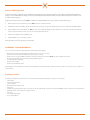
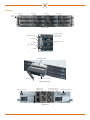
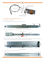
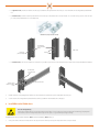
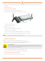
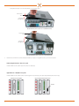
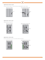
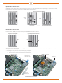
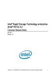
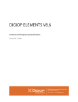
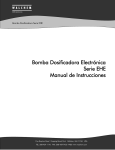
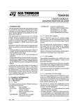
DIGIOP® SV4000 Storage Vault
Hardware Installation and Setup Guide
DIGIOP® SV4000 Chassis for
DIGIOP® Video and Data Management Systems
Congratulations on your new DIGIOP® SV4000 Storage Vault.
This guide provides setup instructions for your server hardware.
For more information, contact DIGIOP® Support at
877.972.2522 Toll Free • [email protected] • www.digiop.com
www.digiop.com
DO_SV4000_PI1
6/10/13
© 2013 DIGIOP, Inc. All rights reserved.
About the SV4000 Storage Vault
The SV4000 Storage Vault is a high performance, high availability data storage appliance that is rack mountable and includes 12 bays for SATA 3.0/6.0 GB hard disk drives (HDDs). This
appliance connects to a DIGIOP® VMS server through a SAS interface controller board (STR-CTRL) installed in the DIGIOP® server chassis. HDDs and fan modules in the SV4000 are easily
accessible for maintenance purposes.
Installation of the SV4000 includes five main steps (NOTE: If the SV4000 was ordered with a DIGIOP® system, steps C, D and E were completed at the factory):
A.
Install the SV4000 chassis into an equipment rack, if preferred. (NOTE: DO NOT power on the SV4000 at this time.)
B.
Install HDDs into the SV4000 chassis. HDDs are shipped separately from the chassis for better protection against shock and damage. These drives need to be installed in the chassis before startup.
C.
Install the STR-CTRL controller card in the DIGIOP® server. NOTE: The controller card is provided with a full height faceplate for installation in server chassis that accommodate them. A half-height
faceplate is provided for installation in an XE, 780, 790, 7010 or other chassis designed for half-height cards.
D.
Install drivers for the STR-CTRL controller in the DIGIOP® system.
E.
Configure the DIGIOP® server to use the SV4000 Storage Vault.
Refer to Specifications the end of this document for more information.
Installation - General Guidelines
Select a location where the SV4000 chassis will be installed that is compliant with the following guidelines:
•
•
•
•
•
•
•
Install the chassis in a climate-controlled environment with a temperature range of 32 °F to 95 °F (0 °C to 35 °C).
Install in a moisture-free environment with a humidity range of 20% to 80% (non-condensing).
Install in a location close enough to the DIGIOP server hardware so that the SAS cable between the two will reach. NOTE: Longer cables are available from your vendor.
The SV4000 chassis can weigh between 33 lb and 55 lb, depending on the HDD configuration.
Use an Uninterrupted Power Supply (UPS).
Keep away from direct sunlight.
Install in an area with minimal dust or debris.
When installing the chassis in an equipment rack, follow the instructions provided with the rack mounting kit. When locating the chassis in the rack, provide at least 1 inch of open space above and below for
adequate ventilation.
Unpacking the Contents
The following are included with your system. Please inspect each system component while unpacking. If any damage is noticed, please contact your provider.
•
•
•
•
•
•
•
•
•
•
2
Quick Start Guide
Software and documentation CD
Surge Protection Notice
Rack installation bracket kit and instructions
SV4000 chassis
STR-CTRL Storage Controller Card and SAS cable (39 in, 1 m. Longer SAS cables are available through your provider.) This card is installed in DIGIOP® systems pre-configured at the factory with the SV4000.
Hard disk drives (number of drives depends on the configuration ordered)
Power cord (2)
Screws for Hard Disk Drives (HDDs)
Keys for locking the HDD trays.
Components
Bay 1, 2, 3
Bay 4, 5, 6
Bay 7, 8, 9
Bay 10, 11, 12
Handle
bracket
Chassis front view
HDD power LED:
Power on: blue
Active: blink
Alarm MUTE button
Power LED
HDD failed LED: red
Alert LED
Temperature LED
Fan LED
Front panel buttons and indicators
HDD tray with HDD
Tray latch lever
Tray latch lever release button
HDD tray in bay (unlatched)
Chassis power switch
Hot-swap blower module
Hot-swap power
supply module (2)
Serial port for console
monitoring (not used)
Chassis ground terminals
2 x 24Gb/s mini-SAS port
Hot-swap blower module
Chassis back view
3
Half-height faceplate installed
Faceplate attachment screw
SAS cable connector
Faceplate attachment screw
SASCABLE1M cable and STR-CTRL card
A. Install the SV4000 chassis with the SV4-RKKIT in an equipment rack
The following instructions apply to the SV4-RKKIT rail kit.
1.
Un-package the SV4-RKKIT rail kit. The rail kit is provided with the rail inner channel nested in the outer channel.
Front of rack
Outer channel
Inner channel
Rail assembly as shipped (inner channel nested in outer channel)
2.
Separate these two channels by sliding the inner channel forward and out of the outer channel. Slide the release latch forward to disengage the detent.
Release latch - slide forward
Outer channel
Inner channel
Separating the inner channel from the outer channel
3.
Position the inner channel on the side of the SV4000 chassis as shown below. Note that the stop tab is near the front of the chassis, and the catches on the sides of the chassis are placed through the slots
in the channel. Secure both channels to the chassis with flat-head screws - one near the middle of the chassis, and one near the back of the chassis.
Chassis
Inner
channel
Screw
Screw
Catch
Slot
Stop tab
Chassis with inner channel attached
4.
Attach the outer channel to the rack using the hardware provided with the rail kit.
This end to back of rack
4
This end to front of rack
——
For square-hole racks, extend the outer channel so that the tangs at each end fit into the square holes in the vertical rack posts. Secure the channel to the rack using hardware provided with the
rack.
——
For round-hole racks, attach the rack brackets provided in the kit to the vertical rack posts. Install two brackets for each outer channel - one on each of the front post, and one on each of the back
post - using screws provided with the rack. See the example below.
Rack brackets (two provided for each rail)
Rack bracket
for round-hole
racks
Inside view
Screws
Rack post
(front or back)
——
For round-hole racks, connect the outer channels to the rack brackets as you would for a square-hole rack. Secure the channel to the post with a retention screw provided with the rack hardware.
Rack bracket
for round-hole
racks
Rail outer channel
Hole for outer
channel retention
screw
5.
Install the chassis in the rack by aligning the inner channels on the chassis with the outer channels in the rack, then carefully slide the chassis into place.
6.
Secure the chassis to the rack using hardware provided with the rack. Holes are provided in the chassis handle brackets for this purpose.
B.
Install HDDs into the SV4000 chassis
Electrostatic Discharge Warning
Electronic modules including the HDDs STR-CTRL controller board, and parts inside the DIGIOP® server chassis contains components that can be damaged by electrostatic discharge (ESD). Always follow
recommended ESD procedures when handling this board and other components inside computers. Use a grounded wrist strap and ESD approved clothing.
Each HDD is labeled for the bay it should be installed into. Drive 1 should be installed in Bay 1, Drive 2 in Bay 2, etc.
1.
Set the power switches on the back of the SV4000 chassis to “off” ( O ). There are three switches, the chassis power switch, and one switch on each power module.
5
2.
Starting at bay 1 and increasing sequentially, remove a drive tray from the bay for each HDD you are installing. To remove the drive tray, push in the tray lever release button, then use the tray lever to pull
the tray out of the bay.
3.
Install an HDD in each drive tray as follows:
NOTE: Use proper ESD procedures when handling HDDs.
a. Position the HDD in the drive tray with the interface connectors toward the back of the tray.
b. Align the screw holes in the sides of the HDD with the back set of holes on the sides of the tray. See the picture below.
Tray latch lever
HDD interface connectors
Screw
Align holes here
c. Secure the HDD to the drive tray with 4 screws, 2 on each side.
d. Repeat steps “a”, “b”, and “c” above for each HDD.
4.
Reinstall the drive trays in the SV4000 chassis as follows:
a. Slide the drive tray with the HDD numbered Drive 1 into Bay 1 until it is fully in place.
b. Push the tray latch lever in until it clicks and is held in place.
c. Repeat steps “a” and “b” above, installing the HDD numbered Drive 2 into Bay 2, Drive 3 into Bay 3, etc. until all HDD trays are installed.
5.
Connect power cables to the both power supply module. Plug them into a UPS (if available) with standard grounded 12 Vac grounded outlets.
NOTE
C.
DO NOT attach the SAS cable to the SV4000 chassis or power on the SV4000 chassis at this time.
Installing the STR-CTRL controller card
The STR-CTRL controller card is provided with a full-height faceplate (installed) and a half -height faceplate for use in these chassis:
•
•
Full-height faceplate with card: Use in the 960, 990, 9010, Power Edge R210 chassis and other chassis requiring cards with full-height faceplates.
Half-height faceplate with card: Use in the XE, 780, 790, 7010 and other chassis requiring cards with half-height faceplates.
Electrostatic Discharge Warning
The DIGIOP® server chassis and the STR-CTRL controller card contain components that can be damaged by electrostatic discharge (ESD). Always follow recommended ESD procedures when handling the
card and other components inside your computers. Use a grounded wrist strap and ESD approved clothing if available. If an ESD wrist strap and ESD protective clothing are not available, touch a bare metal
grounded surface or computer chassis frequently to discharge static from your body.
1.
If you are replacing the STR-CTRL controller in a Power Edge R210 , 960, 990 or 9010 chassis, skip this step and continue with step 2. The XE, 780, 790 or 7010 chassis accept only half height expansion
cards. Since the card is provided with a full height faceplate, replace the faceplate with the half height faceplate provided: .
a. Find a flat surface in a location that is clean, dust free, and away from high voltage devices such as CRTs and power panels.
NOTE: Use proper ESD procedures when handling the controller board.
b. Remove the controller board from the electrostatic protective packaging and lay it face up on the surface.
6
c. Remove the two faceplate retaining screws, then separate the faceplate from the board.
d. Attach the half-height faceplate to the board using the screws removed in the previous step. Tighten the screws until snug. Over tightening the screws can damage the board.
Half-height faceplate installed
Faceplate attachment screw
Faceplate attachment screw
e. Return the board to the electrostatic protective packaging removed previously.
2.
Power off your DIGIOP server hardware (computer).
3.
Unplug the power cord from the back of the chassis, then disconnect ALL other cables from the chassis. Wait 30 seconds before continuing to allow components in the chassis to discharge.
4.
If necessary, move the chassis to a clean surface where it is away from high voltage devices such as CRTs and power panels.
5.
Remove the chassis side cover to gain access to the internal components of the computer.
a. Lay the chassis on its side (mini-tower models) or upright (desktop models), then remove the cover.
»»
WIth the PowerEdge R210 chassis, turn the cover release lock to the unlocked position (left). Slide the cover back about 1/2 inch, then lift it off the chassis.
Unlock
Lock
Cover release lock
Dell PowerEdge R210 cover removal
7
»»
WIth OptiPlex chassis, lift the cover release latch, then lift the cover up and off the chassis.
Cover release
latch
Lift cover at
this edge first
XE, 790, 7010 desktop chassis - remove side cover (7010 chassis shown)
Cover release
latch
Lift cover at
this edge first
960, 990, 9010 minitower chassis - remove side cover (990 chassis shown)
6.
Determine the location where the controller board should be installed in your computer. See the guidelines below for your server chassis and system.
Dell Power Edge R210 II chassis – AI45 series system
Install the STR-CTRL controller card in the expansion slot. This slot is normally empty.
Optiplex XE chassis – EH30/EH35 series systems
Install the STR-CTRL controller card in the fourth slot from the left (right-most slot) when looking at the computer backpanel. Normally the fourth slot is empty.
Original expansion card configuration
Suggested configuration with STR-CTRL controller
STR-CTRL
8
Optiplex XE chassis – EI40 series systems
Originally, the EI40 series systems have no expansion cards. Install the STR-CTRL in the fourth slot from the left.
Optiplex 780 chassis –EH20 series systems
Remove the I/O board from the left slot, then install the STR-CTRL card there. The I/O board can be left out, or can replace the analog audio board in the right slot.
EH2008, EH2016 original expansion card configuration
Analog
audio
card
I/O
card
EH2008, EH2016 suggested configurations with STR-CTRL controller
Analog
audio
card
STR-CTRL
I/O
board
System without I/O card
STR-CTRL
System without audio card
Optiplex 790 chassis –EH21 series systems
In EH2104 systems, move the NIC in the left-most slot to slot 1, then install the STR-CTRL in the left-most slot.
EH2104 original expansion card configuration
EH2104 suggested configuration with STR-CTRL controller
NIC
STR-CTRL
In EH2108 and EH2116 systems, remove the NIC in the forth slot from the left, then install the STR-CTRL into that slot. If the NIC is needed, it can replace the analog audio card in slot 1 (left-most slot), or
the I/O card in slot 2.
EH2108, EH2116 original expansion card configuration
EH2108, EH2116 suggested configurations with STR-CTRL controller
NIC
NIC
STR-CTRL
System without NIC
STR-CTRL
System without I/O card
STR-CTRL
System without audio card
9
Optiplex 790 chassis –EI21 series systems
Move the network interface card (NIC) to the second slot from the left, then install the STR-CTRL in the fourth slot from the left.
Original expansion card configuration
Suggested configuration with STR-CTRL controller
NIC
STR-CTRL
NIC
Optiplex 7010 chassis – EH22 series systems
In the EH2204 system, move the NIC in the forth slot from the left to slot 1, then install the STR-CTRL in the fourth slot from the left.
EH2204 original expansion card configuration
EH2204 Suggested configuration with STR-CTRL controller
NIC
STR-CTRL
In EH2208 and EH2216 systems, remove the NIC in the forth slot from the left, then install the STR-CTRL into that slot. If the NIC is needed, it can replace the analog audio card in slot 1, or the I/O card in
slot 2.
EH2208, EH2216 original expansion card configuration
EH2208. EH2216 suggested configurations with STR-CTRL controller
NIC
NIC
STR-CTRL
System without NIC
10
–
or –
STR-CTRL
System without I/O card
– or – System without audio card
STR-CTRL
Optiplex 7010 chassis –EI22 series systems
Move the network interface card (NIC) to the second slot from the left, then install the STR-CTRL in the fourth slot from the left.
Original expansion card configuration
Suggested configuration with STR-CTRL controller
NIC
STR-CTRL
NIC
Optiplex 960 chassis – AH series systems
Install the STR-CTRL card in the right-most slot.
Original expansion card configuration
Suggested configurations with STR-CTRL controller
STR-CTRL
Optiplex 960 chassis – PH series systems
Move the I/O card from the right slot to the left-most slot, then install the STR-CTRL card in the right slot.
Original expansion card configuration
Suggested configurations with STR-CTRL controller
I/O
card
STR-CTRL
11
Optiplex 990 chassis – AH40 series systems
Install the STR-CTRL controller card in the fourth slot from the left (right-most slot) when looking at the computer backpanel. Because this slot is full, the network interface card (NIC) card in the fourth slot
must be removed. The NIC can be installed in the second slot from the left if the analog audio card is removed, or left out if not needed.
Original expansion card configuration
Suggested configurations with STR-CTRL controller
STR-CTRL
STR-CTRL
Analog
audio
card
NIC
System without NIC
System without audio card
Optiplex 990 chassis – PH50 series systems
Install the STR-CTRL controller card in the fourth slot from the left (right-most slot, originally empty) when looking at the computer backpanel.
Original expansion card configuration
Suggested configuration with STR-CTRL controller
STR-CTRL
Optiplex 990 chassis – AI50 series systems
Move the network interface card (NIC) to the second slot from the left, then install the STR-CTRL in the fourth slot from the left.
Original configuration
Suggested configuration with STR-CTRL controller
NIC
STR-CTRL
NIC
12
Optiplex 9010 chassis – AH41 series systems
Install the STR-CTRL controller card in the fourth slot from the left (right-most slot) when looking at the computer backpanel. Because this slot is full, the analog audio card in the slot must be removed.
The analog audio card can be installed in the second slot from the left if the NIC is removed, or left out if not needed.
Original expansion card configuration
Suggested configurations with STR-CTRL controller
STR-CTRL
STR-CTRL
Analog
audio
card
NIC
System without NIC
– or –
System without analog audio card
Optiplex 9010 chassis – AI51 series systems
Move the network interface card (NIC) to the second slot from the left, then install the STR-CTRL in the fourth slot from the left.
Original expansion card configuration
Suggested configuration with STR-CTRL controller
NIC
STR-CTRL
NIC
7.
Install the STR-CTRL controller card in the suggested location, rearranging other cards in the chassis if necessary. Make sure the board edge connectors of all cards are fully seated in their mainboard
connectors, and the faceplate is positioned properly.
——
In the PowerEdge R210 chassis, the faceplate should align with the opening on the backpanel.
i. Lift open the expansion card latch (see below) and remove the card slot filler bracket.
Expansion card riser
STR-CTRL card installed
Expansion card
latch (shown open)
Expansion card
latch (closed)
Card slot
filler bracket
PowerEdge R210 expansion card installation
13
——
ii.
Place the STR-CTRL card into place (see above), then slide it into the card connecter on the riser.
iii.
Close the expansion card latch.
In OptiPlex chassis, the slot in the upper faceplate tab should surround the alignment pin in card retention latch assembly (see below).
Upper tab of
faceplate
Card retention
latch assembly
Correct positioning
of upper faceplate tab
Proper positioning of XE, 780, 790, 7010 expansion card faceplates
Upper tab of
faceplate
Card retention
latch assembly
Correct positioning
of upper faceplate tab
Proper positioning of 960, 990, 9010 expansion card faceplates
8.
In the PowerEdge R210 chassis, ensure the card is fully seated in the riser. and the card faceplate aligns with the opening on the back of the chassis.
In OptiPlex chassis, roll the card retention latch assembly back into place. The tab should snap into position to lock it.
9.
Reinstall the chassis cover.
10. Reconnect all cables to the chassis.
NOTE
DO NOT attach the SAS cable to the controller or power on the SV4000 chassis at this time.
D.
Install drivers for the STR-CTRL controller card
1.
Power on the DIGIOP server chassis and allow it to fully initialize. Depending on your BIOS configuration, Windows may try to boot through the RocketRAID card; ignore this option; allow the server to
initialize normally.
14
NOTE
Depending on your system BIOS configuration, Windows may try to boot through the RocketRAID card; ignore this screen, and allow the server to initialize.
2.
Open the Device Manager window. (Go to Start u Control Panel u Device Manager.) If this is the first time this controller card is used in the chassis, in the Other devices list you should see a
device named RAID Controller with an alert status. It should be the only device with an alert status.
3.
Right click on RAID Controller to select it, then click Update Driver Software in the pop-up menu. See above.
4.
In the Update Driver Software - RAID Controller window, click the option to Browse my computer for driver software.
5.
If your computer didn’t find drivers for the RocketRAID controller card in your computer, use the CD included with the STR-CTRL board, or download drivers from the web.
a. To install files from the CD provided:
i.
Load the CD into the optical drive
ii.
Open the CD in a file browser
iii.
Copy the path to the CD for use in the window below.
b. To find drivers on Internet:
iv.
Search for: HighPoint RocketRAID 2711 drivers.
v.
Follow the prompts to download drivers for the RocketRAID 2711 card for a Microsoft Windows 7 operating system.
vi.
Save the download file to a location on your computer or network, then decompress the file (Extract All... ) to a directory.
vii. Copy the path to the directory for use in the window below.
15
c. Paste the path to the location where the drivers exist into the Browse entry field in the window shown below, then click Next.
6.
After your computer locates driver files for your system, the window similar to the one shown below will open. Click Install.
7.
If the drivers loaded successfully, the following window will open. Click Close to continue.
8.
When the following window opens, click No. Do not Restart or power off the server at this time.
16
9.
Verify that the Device Manager window does not show an alert status on the RocketRAID icon. See below.
E.
Configuring the DIGIOP® server to use Storage Vault
Configuring the DIGIOP server to use Storage Vault includes the following:
•
•
•
Reassigning the CD-ROM drive letter
Connecting the DIGIOP server to the SV4000 chassis
Configuring the HDDs in the SV4000 chassis to be acknowledged by the DIGIOP server as storage devices
Reassigning the CD-ROM drive letter
1.
At the DIGIOP server, open the Disk Management window.
(Go to Start u Control Panel u Administrative Tools u Computer Management u Storage u Disk Management)
2.
In the bottom center of the window, scroll down through the list of devices to find the CD-ROM entry. In the screen above, it is shown as CD-ROM 0 DVD (E) where the letter in parens (“E”) is the drive
letter.
3.
Right click on the title of the CD-ROM drive, and then select Change Drive Letter and Paths .. .
4.
In the window Change Drive Letter and Paths for E:, Click the Change button.
17
5.
In the Change Drive Letter or Path pop-up window, select Assign the following drive letter, select Z form the drop down list, then click OK. If a verification window opens, click OK to continue.
6.
In the Disk Management screen, verify that the CD-ROM drive letter changed to “Z”.
Connecting the DIGIOP server to the SV4000 chassis
7.
Power off the DIGIOP server.
8.
Connect one end of the SAS cable to the mini SAS port UP connector on the pack of the SV4000 chassis. Connect the other end of the SAS cable to the controller card installed in the DIGIOP server.
Controller card and cable in DIGIOP® server
9.
Power on the SV4000 chassis as follows:
a. Set the two power module power switches to “on” (I).
b. Set the SV4000 chassis power switch to “on” (I).
c. Wait at least 30 seconds for the SV4000 to power on and fully initialize.
10. Power on the DIGIOP® server chassis and allow it to fully initialize.
18
SV4000 SAS cable “UP” connector
11. Open the Disk Management window. In the window shown below, note that volumes 1, 2, 3 and 4 (drives E, F, G and H) of the SV4000 are shown. Verify that for each of these drives have the Status of
Healthy (Primary Partition).
12. Open the Windows file explorer, then open the directory: C:\\DiSSTech\Bin.
13. If you are using a version of DIGIOP ELEMENTS™ before V8.5, skip this step and continue with Step 14. Otherwise, do the following:
a. In the file list, use Notepad (Edit) to open the file DiSSFactory.ini.
b. In the DiSSFactory.ini file, find the entry NO_MCU=1 and insert the following two lines after it:
DRIVESELECTION=1
CUSTOMDRIVEMASK=00000000000000000000000000
where each digit of the 26 digit CUSTOMDRIVEMASK represent a drive letter, A to Z, left to right, of the drives installed in the SV4000 as follows: if the digit is a “1”, the respective drive letter is part of
the SV4000. All other digits are “0”.
In the example used above, with drives E, F, G and H installed in the SV4000, the CUSTOMDRIVEMASK is: 0000111100000000000000000
c. Save the edited DiSSFactory.ini file, and then close Notepad.
d. Skip the following steps. Your SV4000 is now setup and ready for use with your DIGIOP ELEMENTS™ system.
19
Before editing
After editing
14. Complete the following only if you are using a DIGIOP ELEMENTS™ V8.1 or earlier.
a. Open the DIGIOP system in kiosk mode.
b. Click the TOOLS button, then click Pause Recording.
c. Click the System tab, then click the Select Drives button.
20
d. In the Drive Selection menu, select Custom Selection, then
e. In the drive list, select only the drives you want to use for archival storage.
NOTE
DO NOT select the C:\ drive (system drive)
The D:\ drive is the remainder of the internal hard drive.
Do not select any storage that you do not want to use for archives.
f. Click OK to save the setting. Your SV4000 is now setup and ready for use with your DIGIOP ELEMENTS™ system.
SV4000 Storage Vault Specifications
GENERAL
Number of Expander
Single/Dual
Expander Chip
LSISAS2x28
Host Interface
Single Mini SAS 4x connector
Expansion Interface
Single Mini SAS 4x connector
Transfer Bandwidth
2,400MB/s per connector
DRIVES SUPPORTED
Drive Interface
3.0/6.0 Gb dual ported SAS, 1.5/3.0/6.0 Gb single ported SATA
Drive RPM
Up to 15,000
Form Factor
3.5”, 1” height
ADMINISTRATION / MANAGEMENT
Admin/Firmware Upgrade
In-band and Out-of-band, Serial port via Hyper terminal
LED Indicators, Audible Alarm
Yes
HOT-SWAP & REDUNDANCY
Disk Drive (HDD)
Front accessible HDD trays in 12 bay
Cooling
2 x hot-swap blowers
Power Supplies
500 W 1+1 hot-swap redundant 80+ (Sliver)
Power Entry
Dual AC Inlet
ELECTRICAL & ENVIRONMENTAL
Universal A/C Input
100 ~ 240 Vac full range
Operating Environment
Temperature 32 ºF to 95 ºF (0 ºC to 35 ºC), Relative humidity 20% to 80%
Non-operating Environment
Temperature -4 ºF to 140 ºF (-20 ºC to 60 ºC), Relative humidity 10%
to 90%
PHYSICAL SPECIFICATION
Dimensions (W x D x H)
19 x 18.94 x 3.50 in (482.6 x 481 x 88.8 inches: 19 x 19 x 3.5 mm)
Gross Weight (w/ PSU; w/o Rail & Disks)
33 lb (15 kg)
Packaging Dimension (W x D x H)
23.62 x 28.74 x 11.34 in (600 x 730 x 288 mm)
Cubic Feet
5.2
Mounting Option
Adjust plate or toolless rail (optional)
21
22