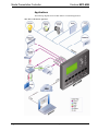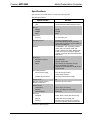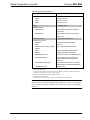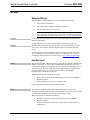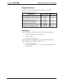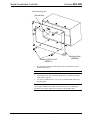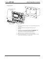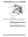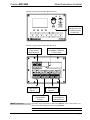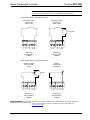
1
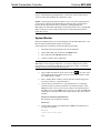
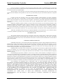
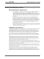
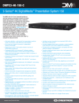
Crestron MPC-M50
MPC Media Presentation Controller™
Operations & Installation Guide
This document was prepared and written by the Technical Documentation department at:
Crestron Electronics, Inc.
15 Volvo Drive
Rockleigh, NJ 07647
1-888-CRESTRON
Regulatory Compliance
This product is Listed to applicable UL Standards and requirements by Underwriters Laboratories Inc.
As of the date of manufacture, the MPC-M50 has been tested and found to comply with specifications for CE
marking and standards per EMC and Radiocommunications Compliance Labelling.
Federal Communications Commission (FCC) Compliance Statement
This device complies with part 15 of the FCC Rules. Operation is subject to the following conditions:
(1) This device may not cause harmful interference and (2) this device must accept any interference received,
including interference that may cause undesired operation.
CAUTION: Changes or modifications not expressly approved by the manufacturer responsible for compliance
could void the user’s authority to operate the equipment.
NOTE: This equipment has been tested and found to comply with the limits for a Class B digital device,
pursuant to part 15 of the FCC Rules. These limits are designed to provide reasonable protection against harmful
interference in a residential installation. This equipment generates, uses and can radiate radio frequency energy
and, if not installed and used in accordance with the instructions, may cause harmful interference to radio
communications. However, there is no guarantee that interference will not occur in a particular installation. If
this equipment does cause harmful interference to radio or television reception, which can be determined by
turning the equipment off and on, the user is encouraged to try to correct the interference by one or more of the
following measures:
Reorient or relocate the receiving antenna
Increase the separation between the equipment and receiver
Connect the equipment into an outlet on a circuit different from that to which the receiver is connected
Consult the dealer or an experienced radio/TV technician for help
Industry Canada (IC) Compliance Statement
This Class B digital apparatus complies with Canadian ICES-003.
Cet appareil numérique de la classe B est conforme à la norme NMB-003 du Canada.
Crestron, the Crestron logo, Crestron Toolbox, Cresnet, e-Control, MPC Media Presentation Controller, QuickMedia, RoomView, SIMPL
Windows, SIMPL+, and SystemBuilder, are trademarks or registered trademarks of Crestron Electronics, Inc. in the United States and other
countries. ColdFire is a registered trademark of Freescale Semiconductor, Inc. in the United States. Windows SideShow is a trademark of the
Microsoft Corporation in the United States and/or other countries. Other trademarks, registered trademarks and trade names may be used in this
document to refer to either the entities claiming the marks and names or their products.
Crestron disclaims any proprietary interest in the marks and names of others.
©2011 Crestron Electronics, Inc
Crestron MPC-M50
Media Presentation Controller
Contents
MPC Media Presentation Controller™: MPC-M50
1
Introduction ............................................................................................................................... 1
Features and Functions ................................................................................................ 1
Applications................................................................................................................. 4
Specifications .............................................................................................................. 5
Physical Description.................................................................................................... 7
Setup ........................................................................................................................................ 12
Network Wiring......................................................................................................... 12
Identity Code ............................................................................................................. 12
Supplied Hardware .................................................................................................... 13
Installation ................................................................................................................. 13
Hardware Hookup ..................................................................................................... 16
Programming Software............................................................................................................ 19
Earliest Version Software Requirements for the PC ................................................. 19
Programming with Crestron SystemBuilder.............................................................. 19
Programming with SIMPL Windows ........................................................................ 19
Push Button Programming ........................................................................................ 20
Uploading and Upgrading........................................................................................................ 21
Establishing Communication..................................................................................... 21
Programs and Firmware ............................................................................................ 22
Problem Solving ...................................................................................................................... 23
Troubleshooting......................................................................................................... 23
System Monitor ......................................................................................................... 24
Check Network Wiring.............................................................................................. 25
Reference Documents................................................................................................ 26
Further Inquiries ........................................................................................................ 26
Future Updates .......................................................................................................... 26
Software License Agreement................................................................................................... 27
Return and Warranty Policies .................................................................................................. 29
Merchandise Returns / Repair Service ...................................................................... 29
CRESTRON Limited Warranty................................................................................. 29
Operations & Installation Guide – DOC. 6814B
Contents • i
Crestron MPC-M50
Media Presentation Controller
MPC Media Presentation
Controller™: MPC-M50
Introduction
Creston® MPC Media Presentation Controller™ is a family of 2-Series control
systems designed for installation in a wall or podium, delivering the industry’s best
multimedia room control technology in a convenient, space saving design. Perfect
for classrooms, meeting rooms, lecture halls and training facilities, the MPC-M50
provides a fully programmable user interface featuring illuminated LCD display,
push buttons with customizable backlit labeling, volume control and wireless remote
capability.
Available in black or white, the MPC-M50 is constructed to handle the rigors of
everyday use in a corporate or educational environment. Numerous programmable
control ports afford plentiful connectivity for a roomful of audio, video and lighting
equipment. The onboard e-Control® Web server provides for complete integration as
part of a facility-wide managed control network.
Features and Functions
•
•
•
•
•
•
•
•
•
•
•
•
•
•
•
•
•
Wall mount 2-Series control system
Programmable LCD display
Volume control knob and menu navigation knob
Seven programmable buttons with LED feedback
Customizable backlit button labels
Built-in IR receiver and light sensor
Two RS-232, two IR, four input and six relay control ports
Cresnet® and 10/100 Ethernet communications
Onboard e-Control® Web server
RoomView® and SNMP remote management
SSL (Secure Sockets Layer) network protection
Astronomical time clock
Exclusively programmable via Crestron SystemBuilder™ software
Rugged construction
3-gang wall mountable
Available in white or black
Includes external Cresnet power supply
Operations & Installation Guide – DOC. 6814B
Media Presentation Controller: MPC-M50 • 1
Media Presentation Controller
Crestron MPC-M50
Control…Simplified
The MPC-M50 is engineered to be easy to integrate and use, yet versatile enough to
suit each application perfectly. Its front panel features a large LCD display with four
“soft keys” plus seven “hard keys” buttons with LED feedback and a volume control
knob, all which can be freely programmed for controlling system functions like
power, source selection, transport control, audio settings, lighting and much more.
The continuous turn “volume” knob provides quick access for adjusting audio
volume and setting values on the LCD display. The soft keys are used to actuate
dynamic menu functions that appear on the display, while the hard keys and LEDs
provide immediate access to the most commonly used functions. Custom backlit
labeling of the hard keys is facilitated using an assortment of pre-printed labels or
Crestron Engraver software.
Configuring a complete MPC media presentation control solution is simplified using
Crestron SystemBuilder™ software, allowing limitless programmability from the
award-winning platform that is familiar to every Crestron dealer. Uploading and
updating a facility full of MPC systems is managed easily over the network or
individually via the front panel USB port.
Wireless Remote
A range of options is available for adding wireless remote control to the MPC
system. Its built-in IR receiver allows use of any Crestron IR wireless touchpanel or
handheld remote without requiring a separate receiver or gateway. For greater range
and freedom of movement, MPC also supports Crestron’s full line of RF wireless
and Wi-Fi based products.
Wired Expansion
With Cresnet® and Ethernet built in, the MPC-M50 works seamlessly with the entire
Crestron line of keypads and touchpanels, lighting dimmers and shade controllers,
signal processors and switchers and much more.
Built-in Control Ports
Through a host of onboard control ports, the MPC-M50 interfaces directly with
video displays and projectors, DVD players, TV receivers, projection screens, lifts,
occupancy sensors and other devices in the room. In addition to Cresnet and highspeed Ethernet, there are two bidirectional RS-232 COM ports, two IR/serial ports,
six isolated relays and four input ports right on the rear panel.
Audio and Video Control
The MPC-M50 is ideal for all kinds of small to medium sized room systems. Like
any 2-Series control system, MPC is fully scalable to suit applications with
numerous program sources, microphones and multiple displays. Use it to control any
Crestron AV switcher or signal processor or as the front end for a system of
QuickMedia® wall plates, FlipTop interfaces, switchers and receivers for a total
signal routing, processing and amplification solution.
Ethernet and e-Control®2
Built-in 10/100 Ethernet facilitates secure high-speed network connectivity, enabling
extensive capabilities for remote system maintenance and control and providing an
interface to other Crestron control systems. The onboard Web server provides the
foundation for Crestron exclusive e-Control®2 XPanel technology, providing secure
IP-based remote control. SSL encryption prevents hackers from breaching the system
and accessing its controls.
2 • Media Presentation Controller: MPC-M50
Operations & Installation Guide – DOC. 6814B
Crestron MPC-M50
Media Presentation Controller
RoomView® and SNMP
The MPC-M50 communicates directly with Crestron RoomView help desk software,
the industry’s most comprehensive facility-wide solution for remote monitoring and
asset management. Built-in SNMP support also enables integration with third-party
network management software, allowing full control and monitoring from the IT
help desk or network operations center in a format that is familiar to IT personnel.
Cresnet® Slave Mode
Selectable Cresnet Slave Mode enables the MPC-M50 to become a Cresnet
controller and expansion module as part of a larger Crestron system, providing a
deluxe user interface with local control ports built in for interfacing to nearby
devices.
Ambient Light Sensor
The MPC-M50’s built-in light sensor has a range of uses, from controlling its own
backlight intensity to providing ambient lighting level data to a central building
management system.
Operations & Installation Guide – DOC. 6814B
Media Presentation Controller: MPC-M50 • 3
Media Presentation Controller
Crestron MPC-M50
Applications
The following diagrams show an MPC-M50 in a residential application.
MPC-M50 in a Residential Application
4 • Media Presentation Controller: MPC-M50
Operations & Installation Guide – DOC. 6814B
Crestron MPC-M50
Media Presentation Controller
Specifications
Specifications for the MPC-M50 are listed in the following table.
MPC-M50 Specifications
SPECIFICATION
DETAILS
Processor
CPU
32-bit Freescale ColdFire® Microprocessor
Memory
SDRAM
32 MB
NVRAM
256 KB
Flash
8 MB
Time Clock
Accuracy
± 1 minute per year
Operating System
Real-time, preemptive multithreaded/multitasking kernel; FAT32 file
system with long names; supports SIMPL™
Windows and SIMPL+®.
Ethernet
10/100BASE-T, auto-negotiating, full/half
duplex, static IP or DHCP, DNS, SSL,
TCP/IP, UDP/IP, CIP, SMTP, SNMP, builtin Web server and e-mail client; supports
Crestron e-Control2 XPanel and RoomView
applications.
IR Receiver
Reception Frequency
36 to 38 kHz IR
Formats
Crestron format, RC5
Range
Up to 50 feet (15 meters) line of sight
typical, dependent upon angle,
obstructions, IR interference and IR remote
signal strength
Power Requirements
Cresnet Power Usage
10 W (0.42 A @ 24 VDC)
power supply included
Available Cresnet Power
8 W using included power supply
Default Net ID
02
Minimum 2-Series Control
System Update File1, 2
Version 4.001.1017 or later
Environmental
Temperature
32º to 104º F (0º to 40º C)
Humidity
10% to 90% RH (non-condensing)
Heat Dissipation
20 BTU/Hr
Enclosure
Faceplate
Plastic, black or white, with label overlay
Chassis
Plastic with steel mounting plate
Mounting
Requires 3-gang plaster ring or electrical
box, ≥2.5 in (64 mm) deep recommended
(Continued on following page)
Operations & Installation Guide – DOC. 6814B
Media Presentation Controller: MPC-M50 • 5
Media Presentation Controller
Crestron MPC-M50
MPC-M50 Specifications (Continued)
SPECIFICATION
DETAILS
Dimensions
Height
4.50 in (114 mm)
Width
6.70 in (170 mm)
Depth
2.23 in (57 mm)
Weight
1.33 lbs (0.61 kg)
Available Models
MPC-M50-B-T
MPC Media Presentation Controller™
M50, black
MPC-M50-W
MPC Media Presentation Controller™
M50, white
Included Accessory
18 W Cresnet Power Pack
Available Accessories
CNSP-XX
Custom Serial Interface Cable
IRP2
IR Probe
MP/MPC/IPAC_FRONT_LABEL[B,W]-T
Set of Engravable Backlit Labels
MP-B3
Media Presentation Button Panels3
4
MP-WP
Media Presentation Wall Plates4
SMK-MP/MPC/IPAC
Swivel Mount Kit for TTK-MP/MPC/IPAC
SW-ROOMVW-ENT
RoomView® Express - Remote Help
Desk and Resource Management
Software
SW-ROOMVW-SERVER
RoomView® Server Edition - Enterprise
Management and Scheduling Software
TTK-MP/MPC/IPAC
TableTop Kit
1. The latest software versions can be obtained from the Crestron Web site. Refer to the NOTE
following these footnotes.
2. Crestron 2-Series control systems include the AV2 and PRO2. Consult the latest Crestron Product
Catalog for a complete list of 2-Series control systems.
3. Media Presentation Button Panels MP-B10/B20-W/B-T
4. Media Presentation Wall Plates
MP-WP100/110/120/125/130/131/140/150/152/160/162/180/185/186/190-B/W
NOTE: Crestron software and any files on the Web site are for authorized Crestron
dealers and Crestron Authorized Independent Programmers (CAIP) only. New users
may be required to register to obtain access to certain areas of the site (including the
FTP site).
6 • Media Presentation Controller: MPC-M50
Operations & Installation Guide – DOC. 6814B
Crestron MPC-M50
Media Presentation Controller
Physical Description
This section provides information on the connections, controls and indicators
available on your MPC-M50.
MPC-M50 Physical View (Front)
MPC-M50 Physical View (Rear)
Operations & Installation Guide – DOC. 6814B
Media Presentation Controller: MPC-M50 • 7
Media Presentation Controller
Crestron MPC-M50
MPC-M50 Overall Dimensions (Front View)
1
2
3
4
8
9
10
4.50 in
(114 mm)
11
5
12
6
13
7
14
6.70 in
(170 mm)
MPC-M50 Overall Dimensions (Rear and Side Views)
15
16
0.95 in
(24 mm)
16
2.60 in
(66 mm)
17
18
19
20
21
1.90 in
(48 mm)
2.23 in
(57 mm)
8 • Media Presentation Controller: MPC-M50
Operations & Installation Guide – DOC. 6814B
Crestron MPC-M50
Media Presentation Controller
Connectors, Controls & Indicators
#
CONNECTORS,
CONTROLS &
INDICATORS
1
LCD DISPLAY
DESCRIPTION
Green LCD dot matrix, 128 x 64 resolution,
adjustable LED backlight
Supports dynamic text and icon graphics,
scrolling text, scrolling lists, Windows®
SideShow® enabled
(1) Programmable continuous turn rotary
encoder for volume adjustment, navigating
menu, scrolling lists and adjusting values
2
VOLUME
3
LIGHT SENSOR
4
IR RECEIVER
5
SOFT KEYS
(4) Push buttons for activation of LCD driven
functions
6
FEEDBACK
INDICATORS
(7) Programmable red LEDs (one per hard
key)
7
HARD KEYS
(7) Programmable buttons with backlit
labeling
8
HOME
(1) Push button, returns to the home page
,
(2) Push buttons, scroll up or down through
menu and adjust menu parameters
9
10
Receives signals from IR transmitter
(1) Push button, executes highlighted menu
or value
ENTER
11
MUTE
12
COMPUTER
Pin 1
Pin 4
Pin 2
Photo sensor, programmable for
auto-dimming of front panel labeling and
other functions
(1) Programmable push button
Pin 3
(1) USB Type B female (behind front cover)
USB 1.1 computer console port
PIN
DESCRIPTION
1
+5 VDC
2
Data -
3
Data +
4
Ground
13
SW-R
(1) Recessed miniature push button (behind
front cover) for software reset (restarts the
SIMPL program)
14
HW-R
(1) Recessed miniature push button for
hardware reset (reboots the processor)
15
NET
(2) Sets of (4) captive screw terminals
Cresnet port and 24 VDC power input with
parallel pass-through
Master/Slave selectable
24:
Y:
Z:
G:
Power (24 VDC)
Data
Data
Ground
(Continued on following page)
Operations & Installation Guide – DOC. 6814B
Media Presentation Controller: MPC-M50 • 9
Media Presentation Controller
Crestron MPC-M50
Connectors, Controls & Indicators (Continued)
#
CONNECTORS,
CONTROLS &
INDICATORS
LAN*
16
YELLOW
LED
PIN 1
GREEN
LED
PIN 8
COM 1
17
DESCRIPTION
(1) 8-pin RJ-45 with two LED indicators
10/100BASE-T Ethernet port
Green LED indicates link status
Yellow LED indicates Ethernet activity
PIN
SIGNAL
PIN
SIGNAL
1
2
3
4
TX +
TX RC+
N/C
5
6
7
8
N/C
RC N/C
N/C
(5) Captive screw terminals
Bidirectional RS-232 port
Up to 115.2 k baud
Hardware and software handshaking support
PIN
COM 2
18
1
TX
2
RX
3
Ground
4
RTS
5
CTS
(2) Captive screw terminals
Bidirectional RS-232 port
Up to 115.2 k baud
Software handshaking support
PIN
RELAYS 1-6
19
(One group of three shown)
DESCRIPTION
DESCRIPTION
1
TX
2
RX
3
Ground
(9) Captive screw terminals comprising (6)
normally open, isolated relays (every two
share a common)
Rated 1 A, 30 VAC/DC
MOV arc suppression across contacts
PIN
DESCRIPTION
1
1
1
2
2
Common
3
2
4
3
5
Common
6
4
7
5
8
Common
9
6
C
Each pair of inputs
shares a common.
(Continued on following page)
10 • Media Presentation Controller: MPC-M50
Operations & Installation Guide – DOC. 6814B
Crestron MPC-M50
Media Presentation Controller
Connectors, Controls & Indicators (Continued)
#
CONNECTORS,
CONTROLS &
INDICATORS
20
IR 1-2
(One group of two shown)
DESCRIPTION
(4) Captive screw terminals comprising (2)
IR/Serial output ports;
IR output up to 1.2 MHz;
1-way serial TTL/RS-232 (0-5 V)
up to 115.2 k baud.
PIN
21
*
INPUTS 1–4
DESCRIPTION
1
Signal
2
Ground
3
Signal
4
Ground
(5) Captive screw terminals comprising (4)
digital or analog input ports (referenced to
GND);
Digital input:
Rated for 0-24 VDC
Input impedance 20 kΩ
Logic threshold 1.25 VDC
Analog input:
Rated for 0-10 VDC
Protected to 24 VDC maximum
Input impedance 20 kΩ
Programmable 5 V, 2 kΩ pull-up resistor per
pin
PIN
DESCRIPTION
1
1
2
2
3
3
4
4
5
Ground
To determine which is pin 1 on the cable, hold the cable so the end of the eight pin modular jack is
facing away from you, with the clip down and copper side up. Pin 1 is on the far left.
Operations & Installation Guide – DOC. 6814B
Media Presentation Controller: MPC-M50 • 11
Media Presentation Controller
Crestron MPC-M50
Setup
Network Wiring
When wiring the Cresnet and Ethernet network, consider the following:
•
Use Crestron Certified Wire.
•
Use Crestron power supplies for Crestron equipment.
•
Provide sufficient power to the system.
CAUTION: Insufficient power can lead to unpredictable results or damage
to the equipment. Please use the Crestron Power Calculator to help calculate
how much power is needed for the system (www.crestron.com/calculators).
Cresnet
For networks with 20 or more devices, use a Cresnet Hub/Repeater (CNXHUB) to
maintain signal quality.
For more details, refer to “Check Network Wiring” which starts on page 25.
Ethernet
The MPC-M50 can also use high-speed Ethernet for communications between the
device and a control system, computer, digital media server and other IP-based
devices.
For information on connecting Ethernet devices in a Crestron system, refer to the
latest version of the Crestron e-Control® Reference Guide (Doc. 6052), which is
available for download from the Crestron Web site (www.crestron.com/manuals).
Identity Code
Net ID
The Net ID of the MPC-M50 has been factory set to 02. This Net ID is defined as the
“Master” control system. The Net IDs of multiple MPC-M50 devices in the same
system must be unique; this means there will be a master/slave relationship between
units (only the Net ID of the master will be left at 02). Net IDs are changed from a
personal computer (PC) via Crestron Toolbox™ (refer to “Establishing
Communication” which starts on page 21).
When setting the Net ID, consider the following:
•
The Net ID of each unit must match an ID code specified in the SIMPL™
Windows program.
•
Each network device must have a unique Net ID.
For more details, refer to the Crestron Toolbox help file.
IP ID
The IP ID is set within the MPC-M50’s table using Crestron Toolbox. For
information on setting an IP table, refer to the Crestron Toolbox help file. The IP IDs
of multiple MPC-M50 devices in the same system must be unique.
When setting the IP ID, consider the following:
•
The IP ID of each unit must match an IP ID specified in the SIMPL
Windows program.
•
Each device using IP to communicate with a control system must have a
unique IP ID.
12 • Media Presentation Controller: MPC-M50
Operations & Installation Guide – DOC. 6814B
Crestron MPC-M50
Media Presentation Controller
Supplied Hardware
The hardware supplied with the MPC-M50 is listed in the following table.
Supplied Hardware for the MPC-M50
DESCRIPTION
PART NUMBER
QUANTITY
Mounting Plate with Ground Wire
4506280
1
Button Identification Labels, Sources, 100
4509400
1
Button Identification Labels, Actions, 100
4509402
1
Screws, 04-40 x 1/4”, Pan, Phil
2007156
2
Screws, 06-32 x 3/4”, Combo Head
2009211
4
2021395 or
2021396*
4
2022867
1
Screws, 04-40 x 1/2”, Btn Head
Prod tool, 1/16” Allen Wrench, L-Key
*
2021395 with black models, 2021396 with white models.
Installation
The following material and tools are required for installation of an MPC-M50:
•
Standard 3-gang electrical box (not included)
•
Philips screwdriver
•
1/16” Allen wrench (included)
After the wiring has been installed and verified, use the following procedure to
install the MPC-M50 in a standard, 3-gang electrical box.
1.
Turn system power OFF.
2.
Use the four included 06-32 x 3/4” screws to attach the mounting plate to
the electrical box.
Operations & Installation Guide – DOC. 6814B
Media Presentation Controller: MPC-M50 • 13
Media Presentation Controller
Crestron MPC-M50
Attach the Mounting Plate
Ground Wire
Screws (4) 06-32 x 3/4"
(2009211)
3.
Mounting Plate
(4506280)
The ground wire from the mounting plate must be attached to an earth
ground (building steel).
NOTE: Ensure the unit is properly grounded.
4.
Attach cables to the rear of the MPC-M50. Refer to “Hardware Hookup”
which starts on page 16.
5.
Use the two included 04-40 x 1/4” screws to attach the MPC-M50 to the
mounting plate.
CAUTION: Excess wire that is pinched between the MPC-M50 and the
electrical box could short out. Make sure that all excess wire is completely
inside the electrical box and not between the box and the MPC-M50.
14 • Media Presentation Controller: MPC-M50
Operations & Installation Guide – DOC. 6814B
Crestron MPC-M50
Media Presentation Controller
Attach the MPC-M50
Screws (2) 04-40 x 1/4"
(2007156)
Label Holder
Button Labels
6.
Attach the label holder by placing it over its slots and sliding it downward
into position.
7.
Attach the included labels in the appropriate positions on the
MPC-M50.
8.
Perform any necessary programming using the COMPUTER (USB)
connection prior to attaching the front panel of the MPC-M50.
(Programming can also be performed via the LAN port.)
9.
Remove the protective coating that covers the LCD display.
10. Use the four included 04/40 x 1/2” screws and the included 1/16” Allen
wrench to attach the front panel to the MPC-M50.
Operations & Installation Guide – DOC. 6814B
Media Presentation Controller: MPC-M50 • 15
Media Presentation Controller
Crestron MPC-M50
Attach the Front Panel
Screws (4) 04-40 x 1/2"
(2021395 or 2021396)
Hardware Hookup
Connect the Device
Make the necessary connections as called out in the illustration that follows this
paragraph. Refer to “Network Wiring” on page 12 before attaching the 4-position
terminal block connector. Apply power after all connections have been made.
When making connections to the MPC-M50, use Creston power supplies for
Crestron equipment.
NOTE: When connecting the included power supply to the NET connector on the
unit, make sure the lead with the white stripes goes to the terminal marked 24. The
other lead goes to the terminal marked G.
NOTE: Ensure the unit is properly grounded by connecting the flying ground lead
on the mounting plate to an earth ground (building steel).
16 • Media Presentation Controller: MPC-M50
Operations & Installation Guide – DOC. 6814B
Crestron MPC-M50
Media Presentation Controller
Hardware Connections for the MPC-M50 (Front View)
COMPUTER
(behind front cover):
To USB Computer
Console Port
Hardware Connections for the MPC-M50 (Rear View)
NET:
To any Cresnet
Network Device
COM:
To any RS-232
Device
RELAYS:
To Controllable
Devices
INPUT Connections
LAN:
10/100Base-T Ethernet
to LAN or Web
IR:
To IRP2 or Serial
Devices
INPUTS:
From Digital or
Analog Devices
Depending on the application, the MPC-M50 INPUTS can be wired multiple ways.
Refer to the following diagrams when wiring INPUTS.
CAUTION: Incorrect wiring may damage the MPC-M50.
Operations & Installation Guide – DOC. 6814B
Media Presentation Controller: MPC-M50 • 17
Media Presentation Controller
Crestron MPC-M50
NOTE: The settings for the pull-up resistor are specified in the SIMPL Windows
program. For more information, refer to the SIMPL Windows help file.
Input Wiring Diagrams – Digital Input Function
Detecting a contact
closure from a
switch or relay
Detecting a contact
voltage from a
switch or relay
+
24 VDC Max
-
1 2
3 4 G
1 2
3 4 G
Digital Input
Digital Input
Pull-up Resistor:
Enabled
Pull-up Resistor:
Disabled
Input Wiring Diagrams – Analog Input Function
Reading a voltage
from an analog
source
Reading
resistance of a
potentiometer
+
10 VDC
-
1 2
Label the Buttons
3 4 G
1 2
3 4 G
Analog Input
Analog Input
Pull-up Resistor:
Disabled
Pull-up Resistor:
Enabled
Optional custom engraved labels for the MPC-M50 can be ordered separately by
using Crestron Engraver software, available from the Crestron Web site
(www.crestron.com).
18 • Media Presentation Controller: MPC-M50
Operations & Installation Guide – DOC. 6814B
Crestron MPC-M50
Media Presentation Controller
Programming Software
Have a question or comment about Crestron software?
Answers to frequently asked questions (FAQs) can be viewed in the Online Help
section of the Crestron Web site. To post a question or view questions you have
submitted to Crestron’s True Blue Support, log in at http://support.crestron.com.
First-time users will need to establish a user account.
Earliest Version Software Requirements for the PC
NOTE: Crestron recommends that you use the latest software to take advantage of
the most recently released features. The latest software is available from the Crestron
Web site (www.crestron.com/software).
NOTE: Crestron software and any files on the Web site are for authorized Crestron
dealers and Crestron Authorized Independent Programmers (CAIP) only. New users
may be required to register to obtain access to certain areas of the site (including the
FTP site).
Crestron provides an assortment of Windows®-based software tools to develop a
customized system. Use Crestron SystemBuilder™ or SIMPL Windows to create a
program to control the MPC-M50.
Programming with Crestron SystemBuilder
The MPC Wizard in Crestron SystemBuilder is the easiest method of programming
the MPC-M50. For additional details, download SystemBuilder from the Crestron
Web site and examine the extensive help file.
Programming with SIMPL Windows
NOTE: While SIMPL Windows can be used to program the MPC-M50, it is
recommended to use SystemBuilder for configuring a system.
SIMPL Windows is Crestron’s premier software for programming Crestron control
systems. It is organized into two separate but equally important “Managers”:
Configuration and Program.
Configuration Manager
Configuration Manager is the view where programmers “build” a Crestron control
system by selecting hardware from the Device Library.
To incorporate the MPC-M50 into the system, drag the MPC-M50 from the Control
Systems folder of the Device Library and drop it in the System Views.
Operations & Installation Guide – DOC. 6814B
Media Presentation Controller: MPC-M50 • 19
Media Presentation Controller
Crestron MPC-M50
Locating the MPC-M50 in the Device Library
Program Manager
Program Manager is the view where programmers “program” a Crestron control
system by assigning signals to symbols.
The symbol can be viewed by double clicking on the icon or dragging it into Detail
View. Each signal in the symbol is described in the SIMPL Windows help file (F1).
Push Button Programming
The four “soft key” push buttons and seven “hard key” push buttons are
programmable and can provide tactile control of many functions such as power,
source selection, transport control, audio settings, lighting and more. Refer to the
following illustration for their assigned join numbers. A description for each button
signal is described in the SIMPL Windows help file (F1).
MPC-M50 Push button Layout and Join Assignment
Soft Keys
(1 - 4)
Press
(1 - 7)
1
1
20 • Media Presentation Controller: MPC-M50
2
2
3
3
4
4
5
6
7
Operations & Installation Guide – DOC. 6814B
Crestron MPC-M50
Media Presentation Controller
Uploading and Upgrading
Crestron recommends using the latest programming software and that each device
contains the latest firmware to take advantage of the most recently released features.
However, before attempting to upload or upgrade it is necessary to establish
communication. Once communication has been established, files (for example,
programs or firmware) can be transferred to the control system (and/or device).
Finally, program checks can be performed (such as changing the device ID or
creating an IP table) to ensure proper functioning.
While the next section provides an overview for communication, refer to
“Establishing Communications with the Control System” in the latest version of the
Crestron 2-Series Control Systems Reference Guide (Doc. 6256) for connection
details. If communications cannot be established, refer to “Troubleshooting
Communications” in the same guide.
Establishing Communication
Use Crestron Toolbox for communicating with the MPC-M50; refer to the Crestron
Toolbox help file for details. There are two methods of communication.
USB
NOTE: Required for initial setup of Ethernet parameters.
NOTE: Required for loading projects and firmware.
USB Communication
PC Running
Crestron Toolbox
USB
MPC-M50
The COMPUTER port on the MPC-M50 connects to the USB port on the PC via a
Type A to Type B USB cable (not included):
1.
Use the Address Book in Crestron Toolbox to create an entry using the
expected communication protocol (USB). When multiple USB devices are
connected, identify the MPC-M50 by entering (for example) “MPC-M50”
in the Model textbox, the unit’s serial number in the Serial textbox or the
unit’s hostname in the Hostname textbox. The hostname can be found in the
“System Info” window in the section marked Ethernet however,
communications must be established in order to see this information in the
“System Info” window.
2.
icon);
Display the MPC-M50’s “System Info” window (click the
communications are confirmed when the device information is displayed.
Operations & Installation Guide – DOC. 6814B
Media Presentation Controller: MPC-M50 • 21
Media Presentation Controller
TCP/IP
Crestron MPC-M50
Ethernet Communication
The MPC-M50 connects to PC via Ethernet:
1.
Establish USB communication between MPC-M50 and PC.
2.
Enter the IP address, IP mask and default router of the MPC-M50 via the
Crestron Toolbox (Functions | Ethernet Addressing); otherwise enable
DHCP.
3.
Confirm Ethernet connections between MPC-M50 and PC. If connecting
through a hub or router, use CAT5 straight through cables with 8-pin RJ-45
connectors. Alternatively, use a CAT5 crossover cable to connect the two
LAN ports directly without using a hub or router.
4.
Use the Address Book in Crestron Toolbox to create an entry for the
MPC-M50 with the MPC-M50’s TCP/IP communication parameters.
5.
Display the “System Info” window (click the
MPC-M50 entry.
6.
Use Crestron Toolbox to create the MPC-M50 IP table.
7.
icon) and select the
a.
Select Functions | IP Table Setup.
b.
Add, modify or delete entries in the IP table. The MPC-M50 can
have only one IP table entry.
c.
A defined IP table can be saved to a file or sent to the device.
When using the MPC-M50 as a “slave”, edit the “master” control system’s
IP table to include an entry for the MPC-M50. The entry should list the
MPC-M50’s IP ID (specified on the MPC-M50’s IP table) and its IP
address.
Programs and Firmware
Program or firmware files may be distributed from programmers to installers or from
Crestron to dealers. Firmware upgrades are available from the Crestron Web site as
new features are developed after product releases. One has the option to upload
programs via the programming software or to upload and upgrade via the Crestron
Toolbox. For details on uploading and upgrading, refer to the SIMPL Windows help
file or the Crestron Toolbox help file.
SIMPL Windows
If a SIMPL Windows program is provided, it can be uploaded to the control system
using SIMPL Windows or Crestron Toolbox.
Firmware
Check the Crestron Web site to find the latest firmware. (New users may be required
to register to obtain access to certain areas of the site, including the FTP site.)
Upgrade MPC-M50 firmware via Crestron Toolbox.
•
Establish communication with the MPC-M50 and display the “System Info”
window.
•
Select Functions | Firmware… to upgrade the MPC-M50 firmware.
22 • Media Presentation Controller: MPC-M50
Operations & Installation Guide – DOC. 6814B
Crestron MPC-M50
Media Presentation Controller
Problem Solving
Troubleshooting
The following table provides corrective action for possible trouble situations. If
further assistance is required, please contact a Crestron customer service
representative.
MPC-M50 Troubleshooting
TROUBLE
POSSIBLE CAUSE(S)
CORRECTIVE ACTION
Unexpected
response from
control system.
Network devices are not
communicating with the
control system.
Use Crestron Toolbox to poll
the network. Verify network
connection to the device.
Top left LED on
front panel is lit
but no response
from device.
Power has been applied
but no program has
been loaded.
Use SIMPL Windows or
Crestron Toolbox to load the
program.
Compilation error
RLCMCVT166 &
RLCMCVT177.
Poor analog versus
serial signal definition in
the SIMPL Windows
program.
Confirm properly defined
signal definition in the
program.
System locks up.
Various.
Press SW-R (behind front
cover) and HW-R buttons at
the same time to bypass
program and communicate
directly with the processor.
Refer to “Troubleshooting
Communications” in the latest
version of the Crestron
2-Series Control Systems
Reference Guide (Doc. 6256)
for more details.
Cresnet device
does not respond.
Device not wired
correctly.
Verify Cresnet wiring.
Improper Net ID used.
Verify that device ID matches
Net ID in the program.
Used wrong IR port.
Verify that proper IR port is
defined.
Device is not receiving
power from a Crestron
power source.
Use the provided Crestron
power source. Verify
connections.
Device is not receiving
sufficient power.
Use the Crestron Power
Calculator to help calculate
how much power is needed
for the system.
Power supply wires not
connected properly.
Verify power supply lead with
white stripes is connected to
NET connector terminal
marked 24. The other lead
should be connected to the
terminal marked G.
A/V system device
does not respond.
Device does not
function.
Operations & Installation Guide – DOC. 6814B
Media Presentation Controller: MPC-M50 • 23
Media Presentation Controller
Crestron MPC-M50
NOTE: If communication cannot be established or the control system is locked up,
refer to “Troubleshooting Communications” in the latest version of the Crestron
2-Series Control Systems Reference Guide (Doc. 6256).
NOTE: Passthrough mode enables Toolbox access to any serial controlled device
on the network. This aids in troubleshooting by allowing direct communication
between the PC and a network device (effectively “passing through” the
MPC-M50). For information pertaining to Passthrough mode, refer to “Passthrough
Mode” in the latest version of the Crestron 2-Series Control Systems Reference
Guide (Doc. 6256)
System Monitor
The System Monitor allows you to reload firmware into the MPC-M50 in the event
that you cannot load the firmware in the normal mode.
If the system does not function, perform the following procedure:
1.
Disconnect all Crestron USB devices from the computer.
2.
On the MPC-M50, press and release the HW-R button.
3.
Press and release the SW-R button three times.
4.
Connect to the PC using a USB cable.
NOTE: If your PC does not have the USB driver installed, after connecting the
MPC-M50 to the PC using the USB cable, you will see a dialog box on your PC
screen asking you to install the USB driver. For instructions on how to install the
USB driver, refer to the Crestron Toolbox help file.
5.
Open Toolbox and start the Text Console (click the
icon). Then, click
on the Address Book icon in the lower left corner of the window to open
the “Address Book” window.
6.
In the “Address Book” window, click the Add Entry button and give the
new entry a name (e.g. “System Monitor”).
7.
Click the arrow next to the Device Type drop-down list. A “Warning”
window will open to inform you that this is an advanced feature. Click
Okay, then select 2-Series Control System Monitor from the drop-down
list. Make sure to choose USB as the Connection Type, then click OK. The
following text will appear in the bottom right corner of the “Text Console”
window:
usb;device 2SeriesCtrlSystemMonitor
The following text will appear in Toolbox:
MONITOR>
8.
At the Toolbox prompt, type erase and press Enter. The following text
will appear in Toolbox:
Erasing
->25%->50%->75%->100%
Done
24 • Media Presentation Controller: MPC-M50
Operations & Installation Guide – DOC. 6814B
Crestron MPC-M50
Media Presentation Controller
9.
Click the
icon and select Firmware… to open the “Firmware”
window, then click Browse.
10. Find and select the correct firmware file (.CUZ or .zip) and click Open.
11. In the “Firmware” window, click Send. You will see a “Confirmation”
window asking if you have selected the right file. Click OK and you will
see the “File Transfer” window.
12. When file transfer is completed, a window asking you to re-connect
appears. Click Okay, then close the “Firmware” window and re-connect
using the normal Address Book entry.
Check Network Wiring
Use the Right Wire
Calculate Power
In order to ensure optimum performance over the full range of your installation
topology, use Crestron Certified Wire only. Failure to do so may incur additional
charges if support is required to identify performance deficiencies because of using
improper wire.
CAUTION: Use only Crestron power supplies for Crestron equipment. Failure to
do so could cause equipment damage or void the Crestron warranty.
CAUTION: Provide sufficient power to the system. Insufficient power can lead to
unpredictable results or damage to the equipment. Please use the Crestron Power
Calculator to help calculate how much power is needed for the system
(www.crestron.com/calculators).
When calculating the length of wire for a particular Cresnet run, the wire gauge and
the Cresnet power usage of each network unit to be connected must be taken into
consideration. Use Crestron Certified Wire only. If Cresnet units are to be daisychained on the run, the Cresnet power usage of each network unit to be daisychained must be added together to determine the Cresnet power usage of the entire
chain. If the unit is home-run from a Crestron system power supply network port, the
Cresnet power usage of that unit is the Cresnet power usage of the entire run. The
wire gauge and the Cresnet power usage of the run should be used in the following
equation to calculate the cable length value on the equation’s left side.
Cable Length Equation
40,000
L<
RxP
Where: L = Length of run (or chain) in feet
R = 6 Ohms (Crestron Certified Wire: 18 AWG (0.75 mm 2 ))
or 1.6 Ohms (Cresnet HP: 12 AWG (4 mm 2 ))
P = Cresnet power usage of entire run (or chain)
Make sure the cable length value is less than the value calculated on the right side of
the equation. For example, a Cresnet run using 18 AWG Crestron Certified Wire and
drawing 20 watts should not have a length of run more than 333 feet (101 meters). If
Cresnet HP is used for the same run, its length could extend to 1250 feet (381
meters).
NOTE: All Crestron certified Cresnet wiring must consist of two twisted pairs. One
twisted pair is the +24V conductor and the GND conductor and the other twisted
pair is the Y conductor and the Z conductor.
Operations & Installation Guide – DOC. 6814B
Media Presentation Controller: MPC-M50 • 25
Media Presentation Controller
Crestron MPC-M50
Strip and Tin Wire
When daisy-chaining Cresnet units, strip the ends of the wires carefully to avoid
nicking the conductors. Twist together the ends of the wires that share a pin on the
network connector and tin the twisted connection. Apply solder only to the ends of
the twisted wires. Avoid tinning too far up the wires or the end becomes brittle.
Insert the tinned connection into the Cresnet connector and tighten the retaining
screw. Repeat the procedure for the other three conductors.
Add Hubs
Use of a Cresnet Hub/Repeater (CNXHUB) is advised whenever the number of
Cresnet devices on a network exceeds 20 or when the combined total length of
Cresnet cable exceeds 3000 feet (914 meters).
Reference Documents
The latest version of all documents mentioned within the guide can be obtained from
the Crestron Web site (www.crestron.com/manuals). This link will provide a list of
product manuals arranged in alphabetical order by model number.
List of Related Reference Documents
DOCUMENT TITLE
2-Series Control Systems Reference Guide
Crestron e-Control Reference Guide
Further Inquiries
If you cannot locate specific information or have questions after reviewing this
guide, please take advantage of Crestron's award winning customer service team by
calling Crestron at 1-888-CRESTRON [1-888-273-7876]. For assistance in your
region, please refer to the Crestron Web site (www.crestron.com) for a listing of
Crestron worldwide offices.
You can also log onto the online help section of the Crestron Web site
(www.crestron.com/onlinehelp) to ask questions about Crestron products. First-time
users will need to establish a user account to fully benefit from all available features.
Future Updates
As Crestron improves functions, adds new features and extends the capabilities of
the MPC-M50, additional information may be made available as manual updates.
These updates are solely electronic and serve as intermediary supplements prior to
the release of a complete technical documentation revision.
Check the Crestron Web site periodically for manual update availability and its
relevance. Updates are identified as an “Addendum” in the Download column.
26 • Media Presentation Controller: MPC-M50
Operations & Installation Guide – DOC. 6814B
Crestron MPC-M50
Media Presentation Controller
Software License Agreement
This License Agreement (“Agreement”) is a legal contract between you (either an individual or a single business entity) and
Crestron Electronics, Inc. (“Crestron”) for software referenced in this guide, which includes computer software and as applicable,
associated media, printed materials and “online” or electronic documentation (the “Software”).
BY INSTALLING, COPYING OR OTHERWISE USING THE SOFTWARE, YOU REPRESENT THAT YOU ARE AN
AUTHORIZED DEALER OF CRESTRON PRODUCTS OR A CRESTRON AUTHORIZED INDEPENDENT PROGRAMMER
AND YOU AGREE TO BE BOUND BY THE TERMS OF THIS AGREEMENT. IF YOU DO NOT AGREE TO THE TERMS OF
THIS AGREEMENT, DO NOT INSTALL OR USE THE SOFTWARE.
IF YOU HAVE PAID A FEE FOR THIS LICENSE AND DO NOT ACCEPT THE TERMS OF THIS AGREEMENT,
CRESTRON WILL REFUND THE FEE TO YOU PROVIDED YOU (1) CLICK THE DO NOT ACCEPT BUTTON, (2) DO NOT
INSTALL THE SOFTWARE AND (3) RETURN ALL SOFTWARE, MEDIA AND OTHER DOCUMENTATION AND
MATERIALS PROVIDED WITH THE SOFTWARE TO CRESTRON AT: CRESTRON ELECTRONICS, INC., 15 VOLVO
DRIVE, ROCKLEIGH, NEW JERSEY 07647, WITHIN 30 DAYS OF PAYMENT.
LICENSE TERMS
Crestron hereby grants You and You accept a nonexclusive, nontransferable license to use the Software (a) in machine
readable object code together with the related explanatory written materials provided by Crestron (b) on a central processing unit
(“CPU”) owned or leased or otherwise controlled exclusively by You and (c) only as authorized in this Agreement and the related
explanatory files and written materials provided by Crestron.
If this software requires payment for a license, you may make one backup copy of the Software, provided Your backup copy
is not installed or used on any CPU. You may not transfer the rights of this Agreement to a backup copy unless the installed copy of
the Software is destroyed or otherwise inoperable and You transfer all rights in the Software.
You may not transfer the license granted pursuant to this Agreement or assign this Agreement without the express written
consent of Crestron.
If this software requires payment for a license, the total number of CPUs on which all versions of the Software are installed
may not exceed one per license fee (1) and no concurrent, server or network use of the Software (including any permitted back-up
copies) is permitted, including but not limited to using the Software (a) either directly or through commands, data or instructions from
or to another computer (b) for local, campus or wide area network, internet or web hosting services or (c) pursuant to any rental,
sharing or “service bureau” arrangement.
The Software is designed as a software development and customization tool. As such Crestron cannot and does not
guarantee any results of use of the Software or that the Software will operate error free and You acknowledge that any development
that You perform using the Software or Host Application is done entirely at Your own risk.
The Software is licensed and not sold. Crestron retains ownership of the Software and all copies of the Software and
reserves all rights not expressly granted in writing.
OTHER LIMITATIONS
You must be an Authorized Dealer of Crestron products or a Crestron Authorized Independent Programmer to install or use
the Software. If Your status as a Crestron Authorized Dealer or Crestron Authorized Independent Programmer is terminated, Your
license is also terminated.
You may not rent, lease, lend, sublicense, distribute or otherwise transfer or assign any interest in or to the Software.
You may not reverse engineer, decompile or disassemble the Software.
You agree that the Software will not be shipped, transferred or exported into any country or used in any manner prohibited
by the United States Export Administration Act or any other export laws, restrictions or regulations (“Export Laws”). By downloading
or installing the Software You (a) are certifying that You are not a national of Cuba, Iran, Iraq, Libya, North Korea, Sudan, Syria or
any country to which the United States embargoes goods (b) are certifying that You are not otherwise prohibited from receiving the
Software and (c) You agree to comply with the Export Laws.
If any part of this Agreement is found void and unenforceable, it will not affect the validity of the balance of the Agreement,
which shall remain valid and enforceable according to its terms. This Agreement may only be modified by a writing signed by an
authorized officer of Crestron. Updates may be licensed to You by Crestron with additional or different terms. This is the entire
agreement between Crestron and You relating to the Software and it supersedes any prior representations, discussions, undertakings,
communications or advertising relating to the Software. The failure of either party to enforce any right or take any action in the event
of a breach hereunder shall constitute a waiver unless expressly acknowledged and set forth in writing by the party alleged to have
provided such waiver.
Operations & Installation Guide – DOC. 6814B
Media Presentation Controller: MPC-M50 • 27
Media Presentation Controller
Crestron MPC-M50
If You are a business or organization, You agree that upon request from Crestron or its authorized agent, You will within
thirty (30) days fully document and certify that use of any and all Software at the time of the request is in conformity with Your valid
licenses from Crestron of its authorized agent.
Without prejudice to any other rights, Crestron may terminate this Agreement immediately upon notice if you fail to comply
with the terms and conditions of this Agreement. In such event, you must destroy all copies of the Software and all of its component
parts.
PROPRIETARY RIGHTS
Copyright. All title and copyrights in and to the Software (including, without limitation, any images, photographs,
animations, video, audio, music, text and “applets” incorporated into the Software), the accompanying media and printed materials
and any copies of the Software are owned by Crestron or its suppliers. The Software is protected by copyright laws and international
treaty provisions. Therefore, you must treat the Software like any other copyrighted material, subject to the provisions of this
Agreement.
Submissions. Should you decide to transmit to Crestron’s Web site by any means or by any media any materials or other
information (including, without limitation, ideas, concepts or techniques for new or improved services and products), whether as
information, feedback, data, questions, comments, suggestions or the like, you agree such submissions are unrestricted and shall be
deemed non-confidential and you automatically grant Crestron and its assigns a non-exclusive, royalty-free, worldwide, perpetual,
irrevocable license, with the right to sublicense, to use, copy, transmit, distribute, create derivative works of, display and perform the
same.
Trademarks. CRESTRON and the Swirl Logo are registered trademarks of Crestron Electronics, Inc. You shall not remove
or conceal any trademark or proprietary notice of Crestron from the Software including any back-up copy.
GOVERNING LAW
This Agreement shall be governed by the laws of the State of New Jersey, without regard to conflicts of laws principles.
Any disputes between the parties to the Agreement shall be brought in the state courts in Bergen County, New Jersey or the federal
courts located in the District of New Jersey. The United Nations Convention on Contracts for the International Sale of Goods shall not
apply to this Agreement.
CRESTRON LIMITED WARRANTY
CRESTRON warrants that: (a) the Software will perform substantially in accordance with the published specifications for a
period of ninety (90) days from the date of receipt and (b) that any hardware accompanying the Software will be subject to its own
limited warranty as stated in its accompanying written material. Crestron shall, at its option, repair or replace or refund the license fee
for any Software found defective by Crestron if notified by you within the warranty period. The foregoing remedy shall be your
exclusive remedy for any claim or loss arising from the Software.
CRESTRON shall not be liable to honor warranty terms if the product has been used in any application other than that for
which it was intended or if it as been subjected to misuse, accidental damage, modification or improper installation procedures.
Furthermore, this warranty does not cover any product that has had the serial number or license code altered, defaced, improperly
obtained or removed.
Notwithstanding any agreement to maintain or correct errors or defects, Crestron shall have no obligation to service or
correct any error or defect that is not reproducible by Crestron or is deemed in Crestron’s reasonable discretion to have resulted from
(1) accident; unusual stress; neglect; misuse; failure of electric power, operation of the Software with other media not meeting or not
maintained in accordance with the manufacturer’s specifications or causes other than ordinary use; (2) improper installation by anyone
other than Crestron or its authorized agents of the Software that deviates from any operating procedures established by Crestron in the
material and files provided to You by Crestron or its authorized agent; (3) use of the Software on unauthorized hardware or (4)
modification of, alteration of or additions to the Software undertaken by persons other than Crestron or Crestron’s authorized agents.
ANY LIABILITY OF CRESTRON FOR A DEFECTIVE COPY OF THE SOFTWARE WILL BE LIMITED
EXCLUSIVELY TO REPAIR OR REPLACEMENT OF YOUR COPY OF THE SOFTWARE WITH ANOTHER COPY OR
REFUND OF THE INITIAL LICENSE FEE CRESTRON RECEIVED FROM YOU FOR THE DEFECTIVE COPY OF THE
PRODUCT. THIS WARRANTY SHALL BE THE SOLE AND EXCLUSIVE REMEDY TO YOU. IN NO EVENT SHALL
CRESTRON BE LIABLE FOR INCIDENTAL, CONSEQUENTIAL, SPECIAL OR PUNITIVE DAMAGES OF ANY KIND
(PROPERTY OR ECONOMIC DAMAGES INCLUSIVE), EVEN IF A CRESTRON REPRESENTATIVE HAS BEEN ADVISED
OF THE POSSIBILITY OF SUCH DAMAGES OR OF ANY CLAIM BY ANY THIRD PARTY. CRESTRON MAKES NO
WARRANTIES, EXPRESS OR IMPLIED, AS TO TITLE OR INFRINGEMENT OF THIRD-PARTY RIGHTS,
MERCHANTABILITY OR FITNESS FOR ANY PARTICULAR PURPOSE, OR ANY OTHER WARRANTIES, NOR
AUTHORIZES ANY OTHER PARTY TO OFFER ANY WARRANTIES, INCLUDING WARRANTIES OF
MERCHANTABILITY FOR THIS PRODUCT. THIS WARRANTY STATEMENT SUPERSEDES ALL PREVIOUS
WARRANTIES.
28 • Media Presentation Controller: MPC-M50
Operations & Installation Guide – DOC. 6814B
Crestron MPC-M50
Media Presentation Controller
Return and Warranty Policies
Merchandise Returns / Repair Service
1.
No merchandise may be returned for credit, exchange or service without prior authorization
from CRESTRON. To obtain warranty service for CRESTRON products, contact an
authorized CRESTRON dealer. Only authorized CRESTRON dealers may contact the factory
and request an RMA (Return Merchandise Authorization) number. Enclose a note specifying
the nature of the problem, name and phone number of contact person, RMA number and
return address.
2.
Products may be returned for credit, exchange or service with a CRESTRON Return
Merchandise Authorization (RMA) number. Authorized returns must be shipped freight
prepaid to CRESTRON, 6 Volvo Drive, Rockleigh, N.J. or its authorized subsidiaries, with
RMA number clearly marked on the outside of all cartons. Shipments arriving freight collect
or without an RMA number shall be subject to refusal. CRESTRON reserves the right in its
sole and absolute discretion to charge a 15% restocking fee plus shipping costs on any
products returned with an RMA.
3.
Return freight charges following repair of items under warranty shall be paid by CRESTRON,
shipping by standard ground carrier. In the event repairs are found to be non-warranty, return
freight costs shall be paid by the purchaser.
CRESTRON Limited Warranty
CRESTRON ELECTRONICS, Inc. warrants its products to be free from manufacturing defects in materials
and workmanship under normal use for a period of three (3) years from the date of purchase from
CRESTRON, with the following exceptions: disk drives and any other moving or rotating mechanical
parts, pan/tilt heads and power supplies are covered for a period of one (1) year; touchscreen display and
overlay components are covered for 90 days; batteries and incandescent lamps are not covered.
This warranty extends to products purchased directly from CRESTRON or an authorized CRESTRON
dealer. Purchasers should inquire of the dealer regarding the nature and extent of the dealer's warranty, if
any.
CRESTRON shall not be liable to honor the terms of this warranty if the product has been used in any
application other than that for which it was intended or if it has been subjected to misuse, accidental
damage, modification or improper installation procedures. Furthermore, this warranty does not cover any
product that has had the serial number altered, defaced or removed.
This warranty shall be the sole and exclusive remedy to the original purchaser. In no event shall
CRESTRON be liable for incidental or consequential damages of any kind (property or economic damages
inclusive) arising from the sale or use of this equipment. CRESTRON is not liable for any claim made by a
third party or made by the purchaser for a third party.
CRESTRON shall, at its option, repair or replace any product found defective, without charge for parts or
labor. Repaired or replaced equipment and parts supplied under this warranty shall be covered only by the
unexpired portion of the warranty.
Except as expressly set forth in this warranty, CRESTRON makes no other warranties, expressed or
implied, nor authorizes any other party to offer any warranty, including any implied warranties of
merchantability or fitness for a particular purpose. Any implied warranties that may be imposed by law are
limited to the terms of this limited warranty. This warranty statement supersedes all previous warranties.
Operations & Installation Guide – DOC. 6814B
Media Presentation Controller: MPC-M50 • 29
Media Presentation Controller
Crestron MPC-M50
This page is intentionally left blank.
30 • Media Presentation Controller: MPC-M50
Operations & Installation Guide – DOC. 6814B
Crestron MPC-M50
Media Presentation Controller
This page is intentionally left blank.
Operations & Installation Guide – DOC. 6814B
Media Presentation Controller: MPC-M50 • 31
Crestron Electronics, Inc.
15 Volvo Drive Rockleigh, NJ 07647
Tel: 888.CRESTRON
Fax: 201.767.7576
www.crestron.com
Operations & Installation Guide – DOC. 6814B
(2024142)
04.11
Specifications subject to
change without notice.