1
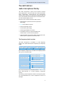
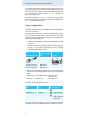
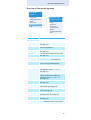
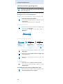
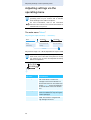
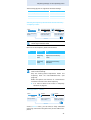
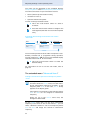
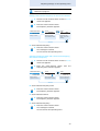
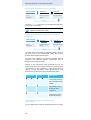
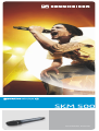
SKM 500
Instruction manual
Contents
Contents
Important safety instructions ............................................... 2
The SKM 500 G3 radio microphone family ......................... 3
The frequency bank system ............................................. 3
Areas of application ............................................................ 4
Delivery includes ....................................................................... 5
Product overview ...................................................................... 6
Overview of the SKM 500 G3 radio microphone ........... 6
Overview of the displays ................................................... 7
Putting the radio microphone into operation .................... 8
Inserting the batteries/accupack ..................................... 8
Charging the accupack ....................................................... 9
Changing the microphone head ....................................... 9
Changing the color-coded protection ring .................. 11
Using the radio microphone ................................................ 12
Switching the radio microphone on/off ..................... 12
Deactivating the lock mode temporarily ..................... 14
Deactivating the RF signal .............................................. 14
Selecting a standard display ......................................... 15
Using the operating menu ................................................... 16
The buttons ...................................................................... 16
Overview of the operating menu ................................. 17
Working with the operating menu .............................. 18
Adjusting settings via the operating menu .................... 20
The main menu “Menu” .................................................. 20
The extended menu “Advanced Menu” ....................... 22
Synchronizing the radio microphone with a receiver ... 26
Synchronizing the radio microphone
with the receiver – individual operation ..................... 26
Synchronizing radio microphones
with receivers – multi-channel operation ................... 26
Cleaning the radio microphone .......................................... 27
Recommendations and tips ............................................... 28
If a problem occurs ... ........................................................... 29
Accessories and spare parts ................................................ 30
Specifications .......................................................................... 31
Polar diagrams and frequency response curves
of the microphone heads ................................................ 32
Manufacturer Declarations .................................................. 34
Index ......................................................................................... 36
An animated instruction manual can be viewed
on the SKM 500 G3 product page on our
website at www.sennheiser.com.
1
Important safety instructions
Important safety instructions
•
Read this instruction manual.
•
Keep this instruction manual. Always include this
instruction manual when passing the product on to third
parties.
•
Heed all warnings and follow all instructions in this
instruction manual.
•
Use only a cloth for cleaning the product.
•
Do not place the product near any heat sources such as
radiators, stoves, or other devices (including amplifiers)
that produce heat.
•
Only use attachments/accessories
Sennheiser.
•
Refer all servicing to qualified service personnel.
Servicing is required if the product has been damaged in
any way, liquid has been spilled, objects have fallen
inside, the product has been exposed to rain or moisture, does not operate properly or has been dropped.
•
WARNING: To reduce the risk of short circuits, do not use
the product near water and do not expose it to rain or
moisture.
specified
by
Replacement parts
When replacement parts are required, be sure the service
technician uses replacement parts specified by Sennheiser
or those having the same characteristics as the original
part. Unauthorized substitutions may result in fire, electric
shock, or other hazards.
Intended use
Intended use of the ew 500 G3 series products includes:
•
having read these instructions especially the chapter
“Important safety instructions”,
•
using the products within the operating conditions and
limitations described in this instruction manual.
“Improper use” means using the products other than as
described in this instruction manual, or under operating
conditions which differ from those described herein.
2
The SKM 500 G3 radio microphone family
The SKM 500 G3
radio microphone family
This radio microphone is part of the evolution wireless
series generation 3 (ew G3). With this series, Sennheiser
offers high-quality state-of-the-art RF transmission
systems with a high level of operational reliability and ease
of use. Transmitters and receivers permit wireless transmission with studio-quality sound.
Features of the evolution wireless 500 G3 series:
•
Optimized PLL synthesizer and microprocessor
technology
•
HDX noise reduction system
•
Pilot tone squelch control
•
True diversity technology
•
Switching bandwidth of 42 MHz
•
Increased immunity to intermodulation and
interferences in multi-channel operation
•
Interchangeable microphone heads, allowing the use of
different pick-up patterns and sensitivities
The frequency bank system
The radio microphone is available in 6 UHF frequency
ranges with 1,680 transmission frequencies per frequency
range:
Range A:
516 – 558
Range G:
566 – 608
Range B:
626 – 668
Range C:
734 – 776
Range D:
780 – 822
Range E:
823 – 865
Each frequency range (A–E, G) offers 26 frequency banks
with up to 32 channels each:
Channel 1 – frequency preset
Channel 2 – frequency preset
Frequency bank 1... 20
Channel 32 – frequency preset
Channel 1 – freely selectable frequency
Channel 2 – freely selectable frequency
Frequency bank U1 ... U6
Channel 32 – freely selectable frequency
Each of the channels in the frequency banks “1” to “20” has
been factory-preset to a fixed frequency (frequency
preset).
The factory-preset frequencies within one frequency bank
are intermodulation-free. These frequencies cannot be
changed.
3
The SKM 500 G3 radio microphone family
For an overview of the frequency presets, please refer to the
supplied frequency information sheet. Updated versions of
the frequency information sheet can be downloaded from
the SKM 500 G3 product page on our website at
www.sennheiser.com.
The frequency banks “U1” to “U6” allow you to freely select
and store frequencies. It might be that these frequencies
are not intermodulation-free.
Areas of application
The radio microphone can be combined with the EM 500 G3
rack-mount receiver.
The EM 500 G3 rack-mount receiver is available in the same
UHF frequency ranges and is equipped with the same
frequency bank system with factory-preset frequencies.
This has the advantage that
•
a transmission system is ready for immediate use after
switch-on,
•
several transmission systems can be operated simultaneously on the preset frequencies without causing
intermodulation interference.
Radio microphone
Interchangeable microphone
heads
Receiver
PEAK
40
30
20
10
RF
SKM 500-935 G3*
SKM 500-945 G3*
SKM 500-965 G3*
MMD 935-1
MMD 945-1
MMK 965-1
0
-10
-20
-30
-40
AF
B.Ch: 20.30
ew500 G3
542.625 MHz
SKM500
EQ
P + 12dB MUTE
EM 500 G3
* The name of the radio microphone is a combination of the
name of the transmitter and the name of the microphone
head:
Transmitter + microphone head = Name of radio
microphone
SKM 500 + MMD 935-1
= SKM 500-935
Overview of the microphone heads:
Microphone
head
Microphone
type
MMD 935-1
dynamic
– cardioid
MMD 945-1
dynamic
– super-cardioid
MMK 965-1
condenser
– cardioid/
super-cardioid,
switchable
Pick-up pattern
The name and pick-up pattern of the microphone head are
printed on the sound inlet basket of the radio microphone.
4
Delivery includes
Delivery includes
The packaging contains the following items:
1 SKM 500 G3 radio microphone incl. microphone head
2 AA size batteries, 1.5 V
1 microphone clamp
1 instruction manual
1 frequency information sheet
1 RF licensing information sheet
1 HHP 2 pouch
5
Product overview
Product overview
Overview of the SKM 500 G3 radio
microphone
쐄
쐆
쐏
쐋
�
쐂
쐇
쐊
쐈
쐅
쐎
쐊
쐉
쐅
쐅
쐃 Microphone head (interchangeable)
쐇 Name and pick-up pattern of the microphone head
(not visible here, see page 4)
쐋 Body of radio microphone
쐏 Battery compartment (not visible from outside)
쐄 Display panel, backlit in orange
쐂 Infra-red interface
쐆 Antenna
쐊 Color-coded protection ring;
available in different colors
쐎 Operation and battery status indicator, red LED
(lit = ON/flashing = LOW BATTERY)
쐅 Charging contacts
쐈 Multi-function switch:
(DOWN), (UP) and
쐉 ON/OFF button
with ESC function (cancel)
6
(SET)
Product overview
Overview of the displays
After switch-on, the radio microphone displays the
standard display “Frequency/Name”. For further illustrations and examples of the different standard displays, refer
to page 15.
The display backlighting is automatically reduced after
approx. 20 seconds.
햲
햳 햴
햵
542.625 MHz
ew500 G3
AF
햶
P MUTE
햷
햸
햹
Display
Meaning
햲 Audio level “AF”
Modulation of the radio microphone with peak hold function
햳 Frequency
Current transmission frequency
햴 Name
Freely selectable name of the
transmitter
햵 Transmission icon RF signal is being transmitted
햶 Lock mode icon
Lock mode is activated
햷 “P” (pilot tone)
Pilot tone transmission is
activated
햸 “MUTE”
Audio signal is muted
햹 Battery status
Charge status:
approx. 100%
approx. 70%
approx. 30%
charge status is
critical, the red
LOW BATTERY LED 쐎
is flashing:
쐎
7
Putting the radio microphone into operation
Putting the radio microphone
into operation
Inserting the batteries/accupack
For powering the radio microphone, you can either use two
1.5 V AA size batteries or the rechargeable Sennheiser
BA 2015 accupack (see “Accessories and spare parts” on
page 30).
Unscrew the lower part of the radio microphone from
the radio microphone’s body 쐋 by turning it counterclockwise.
쐋
When unscrewing the radio microphone during
operation, the muting function is automatically
activated. “MUTE” appears on the display panel.
When screwing the lower part of the radio microphone back to the radio microphone’s body, the
muting is canceled. “MUTE” disappears from the
display panel.
Slide back the lower part of the radio microphone as far
as it will go.
Open the battery compartment cover 씈.
씈
Insert the batteries or the BA 2015 accupack as shown
on the battery compartment cover. Observe correct
polarity when inserting the batteries/accupack.
8
Putting the radio microphone into operation
씈
Close the battery compartment cover 씈.
Push the battery compartment into the radio microphone’s body.
Screw the lower part of the radio microphone back to
the radio microphone’s body 쐋.
Charging the accupack
To charge the radio microphone with the BA 2015 accupack
(see “Accessories and spare parts” on page 30) installed:
Insert the radio microphone into the LA 2 charging
adapter (see “Accessories and spare parts” on page 30)
until it locks into place.
LA 2
L 2015
Plug the LA 2 charging adapter with the inserted radio
microphone into the L 2015 charger (see “Accessories
and spare parts” on page 30).
The LA 2 charging adapter and L 2015 charger can
only charge the radio microphone with the BA 2015
accupack installed. Standard batteries (primary
cells) or individual rechargeable battery cells cannot
be charged in this way.
Changing the microphone head
The microphone head 쐃 is easy to change.
Unscrew the microphone head 쐃.
쐃
9
Putting the radio microphone into operation
Do not touch the contacts of the radio microphone
nor the contacts of the microphone head 쐃. The
contacts can become dirty or damaged if touched.
When unscrewing the microphone head 쐃 during
operation, the muting function is automatically activated. “MUTE” appears on the display panel.
When screwing the microphone head 쐃 back to the
radio microphone, the muting is canceled. “MUTE”
disappears from the display panel.
Screw the desired microphone head to the radio microphone.
The radio microphone is operational again.
10
Putting the radio microphone into operation
Changing the color-coded protection ring
The color-coded protection ring 쐊 prevents the multifunction switch from accidental operation.
Protection rings 쐊 in different colors are available as accessories (see “Accessories and spare parts” on page 30).
The protection rings allow you to clearly identify each radio
microphone.
Remove the color-coded protection ring 쐊 as shown.
쐊
쐊
Put on a new protection ring 쐊 as shown.
쐊
쐊
11
Using the radio microphone
Using the radio microphone
CAUTION! Reduced transmission range
If you touch the antenna 쐆 of the radio microphone, the transmission range will be considerably reduced!
쐆
Only hold the radio microphone by its
body.
To establish a transmission link, proceed as follows:
1. Switch the receiver on
(see the instruction manual of the receiver).
2. Switch the radio microphone on (see next section).
The transmission link is established and the display
backlighting of the receiver changes from red to orange.
It is vital to observe the notes on frequency
selection on page 26.
If you cannot establish a transmission link between radio
microphone and receiver, refer to the chapter “Synchronizing the radio microphone with a receiver” on page 26.
Switching the radio microphone on/off
햵
쐉
쐎
To switch the radio microphone on (online operation):
ON/OFF
12
Briefly press the ON/OFF button 쐉.
The radio microphone transmits an RF signal.
The red ON LED 쐎 lights up. The standard
display “Frequency/Name” appears on the
display panel. The transmission icon 햵 is
displayed.
Using the radio microphone
You can switch the radio microphone on and deactivate the RF signal on switch-on. For more information, see next section.
To switch the radio microphone off:
If necessary, deactivate the lock mode (see page 14).
ON/OFF
Keep the ON/OFF button 쐉 pressed until “OFF”
appears on the display panel. The red ON LED 쐎
goes off and the display panel turns off.
When in the operating menu, pressing the ON/
OFF button 쐉 will cancel your entry (ESC function)
and return you to the current standard display.
To switch the radio microphone on and to deactivate the
RF signal on switch-on (offline operation):
ON/OFF
Keep the ON/OFF button pressed until “RF Mute
On?” appears on the display panel.
Press the multi-function switch.
The transmission frequency is displayed but the
radio microphone does not transmit an RF signal.
The transmission icon 햵 is not displayed. When
the pilot tone function is activated on both radio
microphone and receiver, “RF Mute” appears on
the receiver’s display panel.
542.625 MHz
ew500 G3
AF
햵
P MUTE
Use this function to save battery power or to
prepare a radio microphone for use during live operation without causing interference to existing transmission links.
To activate the RF signal:
ON/OFF
Briefly press the ON/OFF button.
“RF Mute Off?” appears on the display panel.
Press the multi-function switch.
The transmission icon 햵 is displayed again.
13
Using the radio microphone
Deactivating the lock mode temporarily
You can activate or deactivate the automatic lock mode via
the “Auto Lock” menu item (see page 22).
If the lock mode is activated, you have to temporarily deactivate it In order to be able to operate the radio microphone:
Press the multi-function switch.
“Locked“ appears on the display panel.
Move the multi-function switch.
“Unlock?” appears on the display panel.
Press the multi-function switch again.
The lock mode is temporarily deactivated.
How you are using the radio microphone determines how long the lock mode remains deactivated:
When you are in the operating menu
The lock mode remains deactivated until you
exit the operating menu.
When one of the standard displays is shown
The lock mode is automatically activated after
10 seconds.
The lock mode icon 햶 flashes prior to the lock mode being
activated again.
542.625 MHz
ew500 G3
AF
P MUTE
햶
Deactivating the RF signal
Deactivating the RF signal on switch-on
For information on deactivating the RF signal on switch-on,
refer to the chapter “Switching the radio microphone on/
off” on page 13.
Deactivating the RF signal during operation
ON/OFF
When one of the standard displays is shown
on the display panel, briefly press the ON/
OFF button.
“RX Mute On?” appears on the display panel.
Proceed as described under “Switching the radio microphone on/off” on page 12.
14
Using the radio microphone
Selecting a standard display
Move the multi-function switch to select a
standard display.
Contents of the display Selectable standard display
542.625 MHz
ew500 G3
AF
P MUTE
B.Ch: 20.30
542.625 MHz
AF
“Frequency bank/Channel/
Frequency”
P MUTE
ew500 G3
B.Ch: 20.30
AF
“Frequency/Name”
“Name/Frequency bank/
Channel”
P MUTE
15
Using the operating menu
Using the operating menu
A special feature of the Sennheiser ew G3 series is the
consistent, intuitive menu structure of transmitters and
receivers. As a result, adjustments to the settings can be
made quickly – even in stressful situations, for example on
stage or during a live show or presentation.
Make use of the possibility to adjust settings via the
operating menu of the receiver and to transfer these
settings to the radio microphone.
For more information on how to transfer settings
to the radio microphone, refer to the instruction
manual of your receiver. The relevant information is
marked with the sync icon.
The buttons
Button
Function of the button
Press the
ON/OFF
button
•
Switches the radio microphone on
and off
•
Cancels the entry and returns to the
current standard display (ESC function)
•
Activates/deactivates the RF signal
(special function, see page 13)
•
Changes from the current standard
display to the operating menu
•
Calls up a menu item
•
Enters a submenu
•
Stores the settings and returns to the
operating menu
•
Selects a standard display
•
Changes to the next/previous menu
item
•
Changes the setting of a menu item
ON/OFF
Press the
multi-function
switch
Move the
multi-function
switch
16
Using the operating menu
Overview of the operating menu
Main menu
“Menu”
Sensitivity
Frequency Preset
Name
Auto Lock
Advanced
Exit
Display
Extended menu
“Advanced Menu”
Tune
RF Power
Pilot Tone
LCD Contrast
Reset
Software Revision
Exit
Function of the menu item
Main menu “Menu”
Sensitivity
Adjusts the sensitivity “AF”
(see page 20)
Frequency Preset Sets the frequency bank and the
channel (see page 21)
Name
Enters a freely selectable name
(see page 21)
Auto Lock
Activates/deactivates the lock mode
(see page 22)
Advanced
Calls up the extended menu
“Advanced Menu” (see page 22)
Exit
Exits the operating menu and returns
to the current standard display
Extended menu “Advanced Menu”
Tune
Sets the transmission frequencies for
the frequency banks “U1” to “U6”
(see page 22)
Sets the frequency bank, the channel
and the transmission frequency
(frequency banks “U1” to “U6”)
(see page 23)
RF Power
Adjusts the transmission power
(see page 24)
Pilot Tone
Activates/deactivates the pilot tone
transmission (see page 24)
LCD Contrast
Adjusts the contrast of the display
panel (see page 24)
Reset
Resets the settings made in the
operating menu (see page 25)
Software Revision Displays the current software revision
(see page 25)
Exit
Exits the extended menu “Advanced
Menu” and returns to the main menu
17
Using the operating menu
Working with the operating menu
If the lock mode is activated, you have to deactivate
it In order to be able to work with the operating
menu (see page 14).
By way of example of the “Sensitivity” menu, this section
describes how to use the operating menu.
Changing from a standard display to the operating menu
Press the multi-function switch.
The current standard display is replaced by the
main menu.
The last selected menu item is displayed.
Selecting a menu item
Move the multi-function switch to change to the
“Sensitivity” menu item.
The current setting of the menu item is
displayed:
Menu
Sensitivity
–12 dB
Changing and storing settings
Menu
Sensitivity
–12 dB
Call up
“Sensitivity”
Sensitivity
–12 dB
Select the desired
setting
Sensitivity
–36 dB
Store the setting
“Stored”
Press the multi-function switch to call up the
menu item.
Move the multi-function switch to adjust the
input sensitivity.
Press the multi-function switch to store the
setting.
Canceling an entry
ON/OFF
Press the ON/OFF button to cancel the entry.
The current standard display appears on the
display panel.
To subsequently return to the last edited menu item:
Press the multi-function switch repeatedly until
the last edited menu item appears.
18
Using the operating menu
Exiting a menu item
Change to the “Exit” menu item.
Menu
Exit
Confirm your selection.
You return to the next higher menu level.
To directly return to the current standard display:
ON/OFF
Press the ON/OFF button.
19
Adjusting settings via the operating menu
Adjusting settings via the
operating menu
Make use of the possibility to adjust settings via the
operating menu of your receiver and to transfer
these settings to the radio microphone.
For more information, refer to the instruction
manual of the receiver. The relevant information is
marked with the sync icon.
The main menu “Menu”
Adjusting the input sensitivity – “Sensitivity”
Menu
Sensitivity
–12 dB
Call up
“Sensitivity”
Sensitivity
–12 dB
Select the desired
setting
Sensitivity
–36 dB
Store the setting
“Stored”
Adjustment range: 0 to −48 dB, adjustable in steps of 6 dB
The audio level display “AF” 햲 always indicates the
audio level, even if the radio microphone is muted,
e.g. allowing you to check the adjusted sensitivity
before live operation.
B.Ch: 20.30
542.625 MHz
AF
P MUTE
햲
Input sensitivity is
adjusted ...
Effect/display
... too high
Close talking distances, speakers
with loud voices or loud music
passages cause overmodulation in
the transmission link. The audio level
display “AF” 햲 shows full deflection
for the duration of the overmodulation.
... correctly
The audio level display “AF” 햲
shows full deflection only during the
loudest passages.
... too low
The transmission link is undermodulated. This results in a signal with
high background noise.
20
Adjusting settings via the operating menu
The following figures are a guide to the best settings:
Transmission situation
Sensitivity setting
Loud music/vocals
−48 to −18 dB
Presentations
−18 to −12 dB
Interviews
−12 to 0 dB
Selecting the frequency bank and the channel manually –
“Frequency Preset”
Menu
Frequency Preset
B.Ch: 1. 1
Frequency Preset
B.Ch: 1. 1
542.625 MHz
Frequency
B.Ch: 20. 1
533.875 MHz
Call up “Frequency
Preset”
Select the frequency
bank and confirm
Select the channel;
store the setting
“Stored”
When you are in the “Frequency Preset” menu item,
the RF signal is deactivated.
Overview of the frequency banks and channels:
Frequency
bank
“1” to “20”
Channels
Type
up to 32 per System bank:
frequency frequencies are factorybank
preset
“U1” to “U6” up to 32 per User bank:
frequency frequencies are freely
bank
selectable
When setting up multi-channel systems, please
observe the following:
Only the factory-preset frequencies within one
frequency bank are intermodulation-free (see
page 26).
Radio microphone and receiver of a transmission
link have to be set to the same frequency.
It is vital to observe the notes on frequency
selection on page 26.
Entering a name – “Name”
Menu
Name
Lichael
Call up “Name”
Name
Lichael
Name
Michael
Enter a character
and confirm
Enter a character;
store the setting
“Stored”
Via the “Name” menu, you can enter a freely selectable
name (e.g. the name of the performer) for the radio microphone.
21
Adjusting settings via the operating menu
The name can be displayed on the standard displays
“Frequency/Name” and “Name/Frequency bank/Channel”.
The name can consist of up to 8 characters such as:
•
letters (without pronounciation marks),
•
numbers from 0 to 9,
•
special characters and spaces.
To enter a name, proceed as follows:
Move the multi-function switch to select a
character.
Press the multi-function switch to change to the
next segment/character or to store the complete
entry.
Activating/deactivating the automatic lock mode –
“Auto Lock“
Menu
Auto Lock
Active
Auto Lock
Active
Auto Lock
Inactive
Call up “Auto
Lock”
Select the desired
setting
Store the setting
“Stored”
The lock mode prevents that the radio microphone is accidentally switched off or programed during operation.
The lock mode icon 햶
on the current standard display
indicates that the lock mode is activated.
Move the multi-function switch to select the
desired setting.
For information on how to use the lock mode, refer to
page 14.
The extended menu “Advanced Menu”
Setting transmission frequencies and frequency banks –
“Tune”
When you have selected one of the system banks
and then select the “Tune” menu, the radio microphone automatically switches to channel 1 of the
frequency bank “U1”. In this case, “U1.1” briefly
appears on the display panel.
Upon delivery, the channels of the frequency banks
“U1” to “U6” are not assigned a transmission
frequency.
When you are in the “Tune” menu item, the
RF signal is deactivated.
Via the “Tune” menu item, you can set a transmission
frequency to be stored in the current channel or you can
select a different channel in one of the frequency banks
“U1” to “U6” and assign this channel a transmission
frequency.
22
Adjusting settings via the operating menu
It is vital to observe the notes on frequency
selection on page 26.
Setting a transmission frequency for the current channel
Move the multi-function switch until the “Tune”
menu item appears.
Press the multi-function switch.
The frequency selection appears.
Advanced Menu
Tune
542.625 MHz
Tune
542 .625 MHz
B.Ch: U1. 1
Tune
544.625 MHz
B.Ch: U1. 1
Call up “Tune”
Select the MHz
value and confirm
Select the kHz
value; store the
setting
“Stored”
Set the desired frequency.
Press the multi-function switch.
Your settings are stored.
You are back to the operating menu.
Selecting a frequency bank and a channel and assigning
this channel a frequency
Move the multi-function switch until the “Tune”
menu item appears.
Press the multi-function switch until the
frequency bank selection appears.
Advanced Menu
Tune
543.200 MHz
Call up “Tune”
(special function)
Tune
543.200 MHz
B.Ch: U1. 1
Tune
543.200 MHz
B.Ch: U1. 1
Set the frequency
bank and the channel
Set the frequency;
store the setting
“Stored”
Set the desired frequency bank.
Press the multi-function switch.
The frequency selection appears.
Set the desired channel.
Press the multi-function switch.
The frequency selection appears.
Set the desired frequency.
Press the multi-function switch.
Your settings are stored.
You are back to the operating menu.
23
Adjusting settings via the operating menu
Adjusting the transmission power – “RF Power”
Advanced Menu
RF Power
RF Power
Standard
RF Power
Low
Call up
“RF Power”
Select the desired
setting
Store the setting
“Stored”
Via the “RF Power” menu item, you can adjust the transmission power in two steps.
It is vital to observe the notes on the supplied
frequency information sheet.
Activating/deactivating the pilot tone transmission –
“Pilot Tone”
Advanced Menu
Name
Pilot Tone
Call up
“Pilot Tone”
Pilot Tone
Active
Pilot Tone
Inactive
Select the desired
setting
Store the setting
“Stored”
The radio microphone adds an inaudible signal, known as
the pilot tone, to the transmitted signal. The receiver
detects and evaluates the pilot tone.
The pilot tone supports the receiver’s squelch function
(Squelch) and protects against interference due to
RF signals from other devices.
Devices of the ew 500 G1 series (generation 1) do not
support the pilot tone function. Therefore, please observe
the following when combining a radio microphone or
receiver of the ew 500 G3 series (generation 3) with
devices from an earlier evolution wireless generation:
Radio
microphone
Receiver
Make sure to ...
w G3/ w G2
w G3/ w G2
... activate the pilot
tone function on both
radio microphone and
receiver.
w G3
w G1
... deactivate the pilot
tone function on the
ew 500 G3 radio
microphone.
w G1
w G3
... deactivate the pilot
tone function on the
ew 500 G3 receiver.
Adjusting the contrast of the display panel –
“LCD Contrast“
You can adjust the contrast of the display panel in 16 steps.
24
Adjusting settings via the operating menu
Resetting the settings made in the operating menu –
“Reset”
Advanced Menu
Reset
Call up “Reset”
Reset
Yes
Select the desired
setting; apply the
setting
“Stored”
When resetting the settings made in the operating menu,
only the selected settings for the pilot tone and for the
frequency banks “U1” to “U6” remain unchanged.
For an overview of the factory-preset default settings, refer
to the supplied frequency information sheet.
Displaying the software revision – “Software Revision”
You can display the current software revision of the radio
microphone.
For information on software updates, visit the
SKM 500 G3 product page at www.sennheiser.com.
25
Synchronizing the radio microphone with a receiver
Synchronizing the radio
microphone with a receiver
When synchronizing the radio microphone with a receiver,
please observe the following:
Only use a transmitter and a receiver from the
same frequency range (see the type plate on the
transmitter and the receiver).
Make sure that the desired frequencies are listed
in the enclosed frequency information sheet.
Make sure that the desired frequencies are
approved and legal in your country and, if necessary, apply for an operating license.
Synchronizing the radio microphone with
the receiver – individual operation
Upon delivery, the radio microphone and the receiver are
synchronized with each other.
If, however, you cannot establish a transmission link
between radio microphone and receiver, you have to
synchronize the channels of the devices.
For information on automatic synchronization of the radio
microphone with the receiver (individual operation), refer
to the instruction manual of the receiver. This information
is marked with the
icon.
Alternatively, you can set the channel on the radio microphone manually:
Make sure that you set the radio microphone to the
same frequency bank and the same channel as the
receiver (see page 21).
If you still cannot establish a transmission link, refer to the
chapter “If a problem occurs ...” on page 29.
Synchronizing radio microphones with
receivers – multi-channel operation
Combined with ew 500 G3 receivers, ew 500 G3 radio
microphones can form transmission links that can be used
in multi-channel systems.
For information on automatic synchronization of radio
microphones with receivers (multi-channel operation),
refer to the instruction manual of your receiver.
For more information on multi-channel operation, visit the
SKM 500 G3 product page at www.sennheiser.com.
26
Cleaning the radio microphone
Cleaning the radio microphone
CAUTION! Liquids can damage the electronics of the
radio microphone!
Liquids entering the housing of the device
can cause a short-circuit and damage the
electronics.
Keep all liquids away from the radio microphone.
Use a cloth to clean the radio microphone from time to
time.
Do not use any solvents or cleansing agents.
To clean the sound inlet basket of the microphone head
(MMD 935-1, MMD 945-1):
Unscrew the upper sound inlet basket from the
microphone head by turning it counterclockwise (see
diagram).
CAUTION! Liquids will damage the microphone module!
Liquids will damage the microphone module.
Only clean the upper sound inlet basket.
Remove the foam insert.
To clean the sound inlet basket:
– Use a cloth to clean the upper sound inlet basket from
the inside and outside.
OR
– Scrub with a brush and rinse with clear water.
If necessary, clean the foam insert with a mild detergent
or replace the foam insert.
Dry the upper sound inlet basket.
Dry the foam insert.
Reinsert the foam insert.
Replace the sound inlet basket on the microphone head
and screw it tight.
You should also clean the contact rings of the microphone
head from time to time:
Wipe the contact rings of the microphone head with a
cloth.
For information on cleaning the MMK 965-1 microphone head, refer to its instruction manual.
27
Recommendations and tips
Recommendations and tips
... for optimum sound
•
Hold the radio microphone in the middle of the microphone body. Holding it close to the sound inlet basket
will influence the radio microphone’s pick-up pattern.
•
You can vary the bass reproduction by increasing/
decreasing the talking distance.
•
For best results, make sure that the sensitivity is
correctly adjusted.
... for optimum reception
•
Transmission range depends to a large extent on location and can vary from about 10 m to about 150 m.
There should be a “free line of sight” between transmitting and receiving antennas.
•
To avoid overloading the receiver, observe a minimum
distance of 5 m between transmitting and receiving
antennas.
•
Only hold the radio microphone by its body. If you
touch the antenna of the radio microphone, the transmission range will be considerably reduced.
... for multi-channel operation
•
For multi-channel operation, you should only use the
channels within one frequency bank. Each of the
frequency banks “1” to “20” accommodates factorypreset frequencies which are intermodulation-free.
•
When using several transmitters simultaneously,
interference can be avoided by maintaining a
minimum distance of 20 cm between two transmitters.
28
If a problem occurs ...
If a problem occurs ...
Problem
Possible cause
Possible solution
Radio micro- Lock mode is
phone
activated
cannot be
operated,
“Locked”
appears on
the display
panel
Deactivate the lock
mode (see page 14).
No operation indication
Replace the batteries
or recharge the
accupack
(see page 8).
Batteries are flat or
accupack is flat
No RF signal Radio microphone
Set the radio microat the
and receiver are not phone to the same
receiver
on the same channel channel as the
receiver.
Synchronize the
radio microphone
with the receiver
(see page 16).
Transmission range
is exceeded
Reduce the distance
between radio microphone and receiving
antennas.
Increase the transmission power
(see page 24).
RF signal is
deactivated
(“RF Mute“)
Activate the RF
signal (see page 14).
RF signal
available,
no audio
signal,
“MUTE”
appears on
the display
panel
Receiver’s squelch
threshold is
adjusted too high
Reduce the squelch
threshold setting on
the receiver.
Radio microphone
doesn’t transmit a
pilot tone
Activate or deactivate the pilot tone
transmission (see
page 24).
Audio signal
has a high
level of
background
noise or
audio signal
is distorted
Radio microphone’s
sensitivity is
adjusted too low/
too high
Adjust the input
sensitivity
(see page 20).
If a problem occurs that is not listed in the above table or if
the problem cannot be solved with the proposed solutions,
please contact your local Sennheiser partner for assistance.
To find a Sennheiser partner in your country, search at
www.sennheiser.com under “Service & Support”.
29
Accessories and spare parts
Accessories and spare parts
The following accessories are available from your specialist
dealer:
Cat. No.
Product name and description
009950
BA 2015 accupack
009828
L 2015 charger
503162
LA 2 charging adapter
503168
CC 3 system case
004839
MZW 1 wind and pop shield
002155
MZQ 1 microphone clamp
Microphone heads
502577
MMD 935-1 microphone head,
dynamic, cardioid
502579
MMD 945-1 microphone head,
dynamic, super-cardioid
502575
MMD 835-1 microphone head,
dynamic, cardioid
502576
MMD 845-1 microphone head,
dynamic, super-cardioid
501581
MME 865-1 microphone head,
condenser, super-cardioid
502582
MMK 965-1 BK microphone head, color black
externally polarized dual diaphragm condenser
microphone, cardioid/super-cardioid (switchable)
502583
MMK 965-1 BL microphone head, color blue
externally polarized dual diaphragm condenser
microphone, cardioid/super-cardioid (switchable)
502584
MMK 965-1 NI microphone head, color nickel
externally polarized dual diaphragm condenser
microphone, cardioid/super-cardioid (switchable)
30
Specifications
Specifications
RF characteristics
Modulation
wideband FM
Frequency ranges
516–558, 566–608,
626–668, 734–776,
780–822, 823–865 MHz
(A–E, G, see page 3)
Transmission frequencies
1,680 frequencies, tuneable in steps of 25 kHz
20 frequency banks, each
with up to 32 factorypreset channels
6 frequency banks, each
with up to 32 user
programmable channels
Switching bandwidth
42 MHz
Nominal/peak deviation
± 24 kHz/± 48 kHz
Frequency stability
≤ ±15 ppm
RF output power at 50 Ω,
switchable
typ. 10 mW (Low)
typ. 30 mW (Standard)
Pilot tone squelch
can be switched off
AF characteristics
Compander system
Sennheiser HDX
AF frequency response
80–18,000 Hz
Signal-to-noise ratio
(1 mV, peak deviation)
≥ 115 dBA
THD
≤ 0.9 %
Adjustment range of input
sensitivity
48 dB, adjustable
in 6-dB steps
Overall device
Temperature range
−10 °C to +55 °C
Power supply
2 AA size batteries, 1.5 V
or BA 2015 accupack
Nominal voltage
2.4 V
Current consumption:
• at nominal voltage
• with switched-off radio
microphone
typ. 180 mA (30 mW)
≤ 25 μA
Operating time
typ. 8 hrs
Dimensions
approx. ∅ 50 x 265 mm
Weight (incl. batteries)
approx. 450 g
31
Specifications
In compliance with
Europe
EMC
Radio
Safety
EN 301489-1/-9
EN 300422-1/-2
EN 60065
EN 62311 (SAR)
Approved by
Canada
Industry Canada RSS 123
IC: 2099A-G3SKMEM
limited to 806 MHz
USA
FCC-Part 74
FCC-ID: DMO G3SKMEM
limited to 608 MHz
Microphone heads
MMD 935-1 MMD 945-1 MMK 965-1
Microphone
type
dynamic
dynamic
externally
polarized dual
diaphragm
condenser
microphone
Sensitivity
2.5 mV/Pa
1.8 mV/Pa
5.7 mV/Pa /
1.8 mV/Pa
Pick-up
pattern
cardioid
supercardioid
cardioid /
supercardioid,
switchable
Max. SPL
154 dB SPL
154 dB SPL
144 dB SPL /
154 dB SPL
Polar diagrams and frequency response
curves of the microphone heads
Polar diagram MMD 935-1
30°
60°
0°
0
Polar diagram MMD 945-1
30°
30°
5
10
10
60°
60°
15
25
90°
dB
120°
250 Hz
120°
150°
150°
180°
60°
20
25
125 Hz
30°
15
20
90°
0°
0
5
2000 Hz
4000 Hz
90°
90°
dB
120°
125 Hz
250 Hz
120°
150°
150°
180°
2000 Hz
4000 Hz
500 Hz
8000 Hz
500 Hz
8000 Hz
1000 Hz
16000 Hz
1000 Hz
16000 Hz
32
Specifications
Polar diagram MMK 965-1
(cardioid)
Polar diagram MMK 965-1
(super-cardioid)
Frequency response curve MMD 935-1
dBV
-30
-40
-50
-60
-70
-80
50
100
200
500
1.000
1k
2k
5k
10.000
10k
20k
Hz
5k
10.000
10k
20k
Hz
Frequency response curve MMD 945-1
dBV
-30
-40
-50
-60
-70
-80
50
100
200
500
1.000
1k
2k
Frequency response curve MMK 965-1 (cardioid)
dBV
-30
-40
-50
-60
-70
-80
50
100
200
500
Hz
1k
PAD
2k
5k
10k
20k
0° 1 m
Frequency response curve MMK 965-1 (super-cardioid)
dBV
-30
-40
-50
-60
-70
-80
50
100
200
500
PAD
Hz
1k
2k
5k
10k
20k
0° 1 m
33
Manufacturer Declarations
Manufacturer Declarations
Warranty
Sennheiser electronic GmbH & Co. KG gives a warranty of
24 months on this product.
For the current warranty conditions, please visit our web
site at www.sennheiser.com or contact your Sennheiser
partner.
In compliance with the following requirements
•
RoHS Directive (2002/95/EC)
•
WEEE Directive (2002/96/EC)
Please dispose of the radio microphone at the end
of its operational lifetime by taking it to your local
collection point or recycling center for such equipment.
•
Battery Directive (2006/66/EC)
The supplied batteries or rechargeable batteries
can be recycled. Please dispose of them as special
waste or return them to your specialist dealer. In
order to protect the environment, only dispose of
exhausted batteries.
CE Declaration of Conformity
•
•
0682
R&TTE Directive (1999/5/CE)
The declaration is available at www.sennheiser.com.
Before putting the device into operation, please observe
the respective country-specific regulations.
Statements regarding FCC and Industry Canada
This device complies with Part 15 of the FCC Rules and with
RSS-210 of Industry Canada. Operation is subject to the
following two conditions: (1) this device may not cause
harmful interference, and (2) this device must accept any
interference received, including interference that may
cause undesired operation.
This equipment has been tested and found to comply with
the limits for a Class B digital device, pursuant to Part 15 of
the FCC Rules. These limits are designed to provide reasonable protection against harmful interference in a residential
installation. This equipment generates, uses and can
radiate radio frequency energy and, if not installed and
used in accordance with the instructions, may cause
harmful interference to radio communications. However,
there is no guarantee that interference will not occur in a
particular installation. If this equipment does cause harmful
interference to radio or television reception, which can be
determined by turning the equipment off and on, the user
is encouraged to try to correct the interference by one or
more of the following measures:
34
Manufacturer Declarations
•
Reorient or relocate the receiving antenna.
•
Increase the separation between the equipment and
receiver.
•
Connect the equipment into an outlet on a circuit
different from that to which the receiver is connected.
•
Consult the dealer or an experienced radio/TV technician
for help.
This class B digital device complies with the Canadian
ICES-003.
Changes or modifications made to this equipment not
expressly approved by Sennheiser electronic Corp. may void
the FCC authorization to operate this equipment.
Before putting the device into operation, please observe the
respective country-specific regulations!
35
Index
Index
A
Accupack
charging 9
inserting 8
Activating/deactivating
lock mode (Auto Lock) 22
pilot tone 24
Adjusting
contrast (LCD Contrast) 24
input sensitivity (Sensitivity) 20
transmission power 24
Advanced Menu (extended menu)
overview 17
settings 22
AF (audio level) 7
Auto Lock (activating/deactivating the lock mode) 22
B
Batteries, inserting 8
Buttons (function of the ~) 16
C
Channel
assigning a frequency 23
overview 3
selecting (Frequency Preset) 21
selecting (Tune) 22
Charging
accupack 9
battery status display 7
Cleaning (radio microphone) 27
Color-coded protection ring, changing 11
D
Deactivating
lock mode temporarily 14
Displays
adjusting the contrast (LCD Contrast) 24
charge status 7
overview 7
standard displays 15
F
Factory default settings (resetting the settings in the
operating menu) 25
Frequency
preset frequencies 3
~ ranges 3
selecting ~ presets 21
setting the transmission ~ 22
Frequency bank
overview 3
selecting (Frequency Preset) 21
~ system 3
Frequency Preset (selecting a frequency bank/
channel) 21
I
Infra-red transmission 26
Inserting (batteries/accupack) 8
L
LCD Contrast (contrast of the display panel) 24
36
Index
Lock mode
activating/deactivating (Auto Lock) 22
deactivating temporarily 14
Locked (lock mode activated) 14
M
Menu (main menu)
overview 17
settings 20
Microphone heads
changing 9
changing the color-coded protection ring 11
overview 4
pick-up patterns 4
polar diagrams/frequency response curves 32
suitable ~ 4
Modulation (input sensitivity/adjusting the
sensitivity) 20
Multi-channel operation 26
N
Name (entering a name) 21
O
Offline operation (RF signal deactivated) 13
Online operation (RF signal activated) 12
P
Pilot tone
activating/deactivating 24
transmission 24
R
Radio microphone
cleaning 27
resetting (Reset) 25
switching on/off 12
synchronizing with receiver 26
Reset (resetting the settings in the operating menu) 25
RF Mute On/Off (activating/deactivating the RF signal) 13
RF Power (adjusting the transmission power) 24
RF signal
activating (online operation) 12
deactivating (during operation) 14
deactivating (offline operation) 13
S
Selecting (Tune) 23
Sensitivity (adjusting the input sensitivity) 20
Setting up
multi-channel system 26
transmission link 26
Synchronizing (radio microphone/receiver) 26
T
Transmission frequency
selecting (Frequency Preset) 21
setting (Tune) 22
Transmission link, establishing 26
Transmission power, optimizing 28
Troubleshooting 29
Tune (setting a transmission frequency) 22
U
Unlock (deactivating the lock mode) 14
Using
operating menu 18
radio microphone 12
37
Sennheiser electronic GmbH & Co. KG
Am Labor 1, 30900 Wedemark, Germany
www.sennheiser.com
Printed in Germany
Publ. 01/09
529673/A01