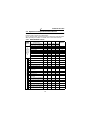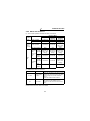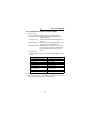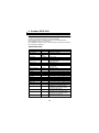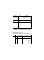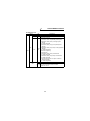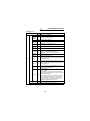
1
MITSUBISHI ELECTRIC
FR-A5NPA
Frequency Inverter
Instruction Manual
Profibus/DP
Communication Option
Art. no.: 146529
01 02 2003
Version B
IB(NA)-0600095-B
MITSUBISHI ELECTRIC
INDUSTRIAL AUTOMATION
Thank you for choosing the Mitsubishi transistorized inverter option unit.
This instruction manual gives handling information and precautions for use of
this equipment. Incorrect handling might cause an unexpected fault. Before using
the equipment, please read this manual carefully to use the equipment to its
optimum.
This section is specifically about safety matters
Do not attempt to install, operate, maintain or inspect this product until you
have read through this instruction manual and appended documents carefully
and can use the equipment correctly. Do not use this product until you have a
full knowledge of the equipment, safety information and instructions.
In this instruction manual, the safety instruction levels are classified into
"WARNING" and "CAUTION".
WARNING
Assumes that incorrect handling may cause
hazardous conditions, resulting in death or
severe injury.
CAUTION
Assumes that incorrect handling may cause
hazardous conditions, resulting in medium or
slight injury, or may cause physical damage only.
Note that the CAUTION level may lead to a serious consequence according to
conditions. Please follow the instructions of both levels because they are
important to personnel safety.
SAFETY INSTRUCTIONS
1. Electric Shock Prevention
WARNING
• While power is on or when the inverter is running, do not open the front
cover. You may get an electric shock.
• Do not run the inverter with the front cover removed. Otherwise, you may
access the exposed high-voltage terminals and charging part and get an
electric shock.
• If power is off, do not remove the front cover except for wiring or periodic
inspection. You may access the charged inverter circuits and get an electric
shock.
• Before starting wiring or inspection, switch power off, wait for more than 10
minutes, and check for no residual voltage with a tester or the like.
WARNING
• Any person who is involved in the wiring or inspection of this equipment
should be fully competent to do the work.
• Always install the option unit before wiring. Otherwise, you may get an
electric shock or be injured.
• Handle this option unit with dry hands to prevent an electric shock.
• Do not subject the cables to scratches, excessive stress, heavy loads or
pinching. Otherwise, you may get an electric shock.
• While power is on, do not move the station number and baud rate setting
switches. Doing so can cause an electric shock.
A-1
2. Injury Prevention
CAUTION
• Apply only the voltage specified in the instruction manual to each terminal to
prevent burst, damage, etc.
• Ensure that the cables are connected to the correct terminals. Otherwise,
burst, damage, etc. may occur.
• Always make sure that polarity is correct to prevent burst, damage, etc.
• While power is on or for some time after power-off, do not touch the inverter
as it is hot and you may get burnt.
3. Additional instructions
Also note the following points to prevent an accidental failure, injury, electric
shock, etc.:
(1) Transportation and mounting
CAUTION
•
•
•
•
Do not install or operate the option unit if it is damaged or has parts missing.
Do not stand or rest heavy objects on the product.
Check that the mounting orientation is correct.
Prevent screws, metal fragments or other conductive bodies or oil or other
flammable substance from entering the inverter.
(2) Test operation and adjustment
CAUTION
• Before starting operation, confirm and adjust the parameters. A failure to do
so may cause some machines to make unexpected motions.
(3) Usage
WARNING
• Do not modify the equipment.
CAUTION
• When parameter clear or all parameter clear is performed, each parameter
returns to the factory setting. Re-set the required parameters before starting
operation.
• For prevention of damage due to static electricity, touch nearby metal before
touching this product to eliminate static electricity from your body.
(4) Maintenance, inspection and parts replacement
CAUTION
• Do not test the equipment with a megger (measure insulation resistance).
(5) Disposal
CAUTION
• Treat as industrial waste.
(6) General instruction
All illustrations given in this manual may have been drawn with covers or safety
guards removed to provide in-depth description. Before starting operation of
the product, always return the covers and guards into original positions as
specified and operate the equipment in accordance with the manual.
A-2
CONTENTS
1. PRE-OPERATION INSTRUCTIONS
1.1
1.2
1.3
1.4
1.5
1
Unpacking and Product Confirmation ............................................... 1
Packing Confirmation........................................................................ 1
Structure ........................................................................................... 2
Inverter Specifications ...................................................................... 3
Communication Specification ........................................................... 3
2. INSTALLATION
4
2.1 Pre-Installation Instructions .............................................................. 4
2.2 Inverter Node Address Setting.......................................................... 4
2.3 Installation and Removal Procedure................................................. 5
2.3.1 Profibus Communication Cable ................................................. 7
3. INVERTER SETTING
8
3.1 List of Dedicated Communication Parameters ................................. 8
3.2 Operation Mode ................................................................................ 9
3.2.1 Operation mode indication......................................................... 9
3.2.2 Operation mode switching ....................................................... 10
3.3 Operation and Speed Command Source........................................ 15
3.3.1 FR-A500/F500 series............................................................... 15
3.3.2 FR-V500 series........................................................................ 17
3.4 Operation at Communication Error Occurrence ............................. 19
3.4.1 Operation selection at communication error occurrence (For the
FR-A500/V500 series only)...................................................... 19
3.4.2 Alarm and measures................................................................ 23
3.4.3 Inverter reset............................................................................ 24
3.5 Instructions ..................................................................................... 24
4. FUNCTION OVERVIEW
25
4.1 Function Overview .......................................................................... 25
4.1.1 Input from master module to inverter....................................... 26
4.1.2 Output from inverter to master module .................................... 27
5. Profibus PROFILES
28
5.1 Profibus Device Data ...................................................................... 28
5.2 Slave User Parameter .................................................................... 30
5.3 Profibus Profiles.............................................................................. 31
5.3.1 ID definitions ............................................................................ 31
5.3.2
5.3.3
Buffer memory map ................................................................. 32
Points to note........................................................................... 32
6. BUFFER MEMORY DETAILS
6.1
6.2
33
FR-A500/F500 Series ..................................................................... 33
FR-V500 Series .............................................................................. 40
7. PARAMETER DEFINITIONS - A500/F500 SERIES
47
7.1 Outline of PNU................................................................................ 47
7.2 Profibus PNU .................................................................................. 48
7.2.1 Real-time monitor .................................................................... 48
7.2.2 Parameter clear ....................................................................... 50
7.2.3 Operation mode read/write ...................................................... 50
7.2.4 Set frequency read .................................................................. 50
7.2.5 Terminal input read.................................................................. 50
7.2.6 Inverter reset............................................................................ 50
7.2.7 Node address read .................................................................. 51
7.2.8 Alarm history............................................................................ 51
7.2.9 PNU list read............................................................................ 52
7.3 Standard Parameters..................................................................... 53
8. PARAMETER DEFINITIONS - V500 SERIES
56
8.1 Outline of PNU................................................................................ 56
8.2 Profibus PNU .................................................................................. 57
8.2.1 Real-time monitor .................................................................... 57
8.2.2 Parameter clear ....................................................................... 59
8.2.3 Operation mode read/write ...................................................... 59
8.2.4 Set frequency read .................................................................. 59
8.2.5 Terminal input read.................................................................. 60
8.2.6 Inverter reset............................................................................ 60
8.2.7 Node address read .................................................................. 60
8.2.8 Alarm history............................................................................ 61
8.2.9 PNU list read............................................................................ 62
8.3 Standard Parameters...................................................................... 63
9. TROUBLESHOOTING
66
1. PRE-OPERATION INSTRUCTIONS
1.1 Unpacking and Product Confirmation
Take the option unit out of the package, check the unit name, and confirm
that the product is as you ordered and intact.
Note that the FR-A500/F500 series inverter and FR-V500 series inverter
have different functions when the option is fitted.
Please check the SERIAL number of the inverter when using the FR-V500
series.
• SERIAL number check
•This product may be used with the FR-V500 series manufactured in and
after May 2002. Any of the models may be used with this unit if its
SERIAL number indicated on the rating plate and package has
"!25!!!!!!" or later version. For details on the SERIAL number,
please contact your sales representative.
SERIAL is made up of 1 version symbol, 1 alphabet letter or numeric
character indicating month, and 7 numeric characters indicating year
and control number as shown below. (Only the first three digits of the
control number are printed on the package.)
2
5
!!!!!!
!
Symbol Year Month Control number
SERIAL number
1.2 Packing Confirmation
Make sure that the package includes the following
" Instruction manual.........................................................................1
" Mounting screws M3 × 6 ...............................................................2
1
PRE-OPERATION INSTRUCTIONS
1.3 Structure
Front view
Mounting
hole
Mounting
hole
FR-A5NPA
CD
AB E
45
23 6
F01
SW1
789
Node address switch
Mounting
hole
Rear view
Mounting
hole
connector
Name
Operating status indicator
LEDs (green)
Profibus connector
(Dsub9 pin connector)
CD
AB E
Operating status
indicator LED Option fixing hole
Option fixing hole
Node address setting
switches
789
SW2
45
23 6
F01
Profibus connector
(Dsub9 pin connector)
Function
Used to set the inverter station number between 0H
and 7DH.
For details, refer to page 4.
off
Communication stops
on
During communication
Used to connect a Profibus cable for Profibus
communication (Refer to page 7.)
2
PRE-OPERATION INSTRUCTIONS
1.4 Inverter Specifications
Type
Inverter inboard option, to be connected with a connector
(can be mounted/dismounted to/from the inverter front face)
Number of node
occupied
One inverter occupies one node.
Cable
For 12Mbps communication
(compliant with EEIA-RS-485 standard)
* When the option unit (FR-A5NPA) is plugged in, the protective structure
(JEM1030) is open type (IP00).
1.5 Communication Specification
Wiring length 1200m
maximum
Wiring length 600m
Communication maximum
speed
Wiring length 200m
maximum
Wiring length 100m
maximum
9600bps, 19.2Kbps, 93.75Kbps
187.5Kbps
500Kbps, 1.5Mbps
3Mbps, 6Mbps, 12Mbps
3
2. INSTALLATION
2.1 Pre-Installation Instructions
Make sure that the input power of the inverter is off.
CAUTION
With input power on, do not install or remove the option unit.
Otherwise, the inverter and option unit may be damaged.
2.2 Inverter Node Address Setting
Set the node address of the inverter on the Profibus network.
Set the inverter node address before switching on the inverter and do not
change the setting while power is on.
The node address may be set between 0H and 7DH.
CAUTION
1. Do not set the node address to 7EH through FFH.
2. Depending on the master module, 0H, 1H, 2H, 7CH, 7DH may not
be used.
3. The node address changed while powering on the inverter is not
made valid. The node address setting is made valid either after
power is reapplied or when the RES signal turns on.
4. You cannot set the same node address to other devices on the
network. (Such setting disables normal communication.)
CD
AB E
789
CD
AB E
F01
SW2
45
23 6
789
•For node address 7DH:
Set (%) SW1 to "7" and the (%) SW2 to "D".
F01
SW1
45
23 6
$ Set the arrow (%) of the corresponding switch to the
required numeral.
Example:
•For node address 1H:
Set (%) of SW1 to "0" and (%) of SW2 to "1".
45
23 6
CD
AB E
F01
SW1
789
45
23 6
CD
AB E
F01
SW2
789
REMARKS
CD
AB E
F01
789
CD
AB E
Bad example
F01
45
23 6
789
4
Good example
45
23 6
Set each node address switch to the
position of its numeral without error. If it is
set to any position between numerals,
normal data communication cannot be
made.
INSTALLATION
2.3 Installation and Removal Procedure
Mount the option unit to slot 3.
(1) Remove the front cover from the inverter and remove the DATA PORT
cover by pushing it from the back of the front cover.
(2) Securely insert the connector of the option unit far into the connector
of slot 3 in the inverter. At this time, fit the option fixing holes snugly.
For the position of slot 3, refer to the illustration below.
Also be sure to fit the unit into the option fixing hook (For the FR-A500/
FR-F500 series, it is available in Aug., 2000).
(3) Securely fix the option unit to the inverter on both sides with the
accessory mounting screws. If the screw holes do not line up, the
connector may not have been plugged snugly. Check for loose
plugging.
(4) Reinstall the front cover of the inverter. (Refer to the inverter manual.)
(5) Connect a Profibus communication cable to the Profibus connector
(Dsub9 pin connector) of the option. (Refer to page 7 for a
communication cable.)
Inverter
(Without cover)
Slot 1
Accessory screw
(2 pcs.)
Slot 2
Option fixing hook
DATA PORT
Inverter side connector
Slot 3
Option unit
(FR-A5NPA)
Dsub9 pin
male
connector
Profibus communication
cable
The slots 1, 2, and 3 are provided
with an option fixing hook.
5
INSTALLATION
(6) To remove the option unit, remove the two left and right screws, and
then hold the option unit and pull its bottom toward you as shown in the
figure. (The option unit is fixed by the hook of the inverter.)
REMARKS
Perform wiring after the option unit (FR-A5NPA) was fitted and the inverter front
cover was mounted.
The option unit (FR-A5NPA) is valid only if it is fitted in slot 3.
When two or more communication option units are mounted, "E.OPT" error is
displayed. Note that when the relay output/computer link unit (FR-A5NR) is
mounted, only relay output is activated.
6
INSTALLATION
2.3.1 Profibus Communication Cable
Make a network communication cable using a Dsub9 pin male connector
and a cable supporting 12Mbps communication.
(1) Pin arrangement of a connector
1 2 3 4 5
6 7 8 9
Dsub9 pin type male
Signal
connector pin number
1
SHIELD
2
N/C
3
RxD/TxD+
4
RTS *1
5
6
7
8
9
DGND *2
+5VDC *2
N/C
RxD/TxDN/C
Application
Shield
Unconnected
Receive/transmit + data
Control signal (transmission request
from the inverter)
Data earth
Voltage output
Unconnected
Receive/transmit - data
Unconnected
*1 It may not be necessary depending on the master module used.
*2 This signal is used to make the terminating resistor present.
(2) Terminating resistor
If the nodes at both ends of the network are the FR-A5NPA and
inverter, connect a connector with a built-in terminating resistor.
R1
R2
R3
1 2 3 4 5
R1=390Ω±2% 1/4W
R2=220Ω±2% 1/4W
R3=390Ω±2% 1/4W
6 7 8 9
7
3. INVERTER SETTING
3.1 List of Dedicated Communication Parameters
When this option unit is mounted, extended functions of the following
parameters become available.
Perform setting as required.
FR-A500/F500 series parameter
Parameter
Number
Setting Minimum Factory Refer
to
Setting
Range Increments Setting page
Name
Operation control
0, 1
1
0
command source
339
Speed command source
0, 1
1
0
Link startup mode
340
0 to 2
1
0
selection
0 to
Communication error
500(*1)
0.1s
0
recognition waiting time
999.8s
Communication error
501(*1)
0
1
0
occurrence count display
Communication error-time
502(*1)
0 to 2
1
0
stop mode selection
*1 Pr. 500 to Pr. 502 are available only with the FR-A500 series.
Refer to the inverter manual for the availability of the parameters.
338
15
15
12
19
20
21
FR-V500 series parameter
Parameter
Number
338
339
340
400
401
402
500
501
502
Setting
Range
Name
Operation control
0, 1
command source
Speed command source
0, 1
Link startup mode
0 to 2
selection
DI11 terminal function
0 to 3, 5,
selection
8 to 12,
14 to 16, 20,
DI12 terminal function
selection
22 to 27,
42 to 44,
DI13 terminal function
9999
selection
Communication error
0 to 999.8s
recognition waiting time
Communication error
0
occurrence count display
Communication error-time
0 to 2
stop mode selection
8
Minimum Factory Refer
Setting
to
Increments Setting page
1
0
17
1
0
17
1
0
12
1
9999
—
0.1s
0
19
1
0
20
1
0
21
INVERTER SETTING
3.2 Operation Mode
The inverter mounted with the option unit (FR-A5NPA) has the following
operation modes:
(1) PU operation [PU] ................. Controls the inverter from the keyboard
of the operation panel (FR-DU04(-1)) or
parameter unit (FR-PU04(V)) (referred
to as the "PU") installed to the inverter.
(2) External operation [EXT] ....... Controls the inverter by switching on/off
external signals connected to the
control circuit terminals of the inverter.
(3) Network operation [NET] ....... Controls the inverter with instructions
from the Profibus master module via the
option unit (FR-A5NPA).
(The operation signal and running
frequency can be entered from the
control circuit terminals depending on
the Pr. 338 "operation control command
source" and Pr. 339 "speed command
source" setting.)
3.2.1 Operation mode indication
FR-DU04(-1)
CONTROL PANEL
Hz
A
V
MON
EXT
PU
REV
FWD
Operation mode indication (lit)
PU : PU operation mode
EXT: External operation mode
Network operation mode
FR-PU04(V)
OL
Hz
STF
FWD
PU
Operation mode indication
PU : PU operation mode
EXT: External operation mode
NET: Network operation mode
9
INVERTER SETTING
3.2.2 Operation mode switching
(1) Operation mode switching conditions
Before switching the operation mode, check that:
1) The inverter is at a stop;
2) Both the STF and STR signals are off; and
3) The Pr. 79 "operation mode selection" setting is correct.
(For setting, use the inverter's operation panel or optional
parameter unit.)
Pr. 79
Setting
0
1
2
3, 4
5*1
6
7
8
Switching to Network Operation
Mode
Disallowed when the PU mode is
PU or external operation
selected. Allowed when the external
mode is selected.
PU operation
Disallowed
External operation
Allowed
External/PU combined operation Disallowed
Operation Mode Selection
Programmed operation
Disallowed
Switch-over
Allowed
Allowed only in the external operation
External operation
mode when the PU interlock signal
(PU operation interlock)
(X12) is on.
Allowed only in the external operation
PU or external (signal switching)
mode (X16 on).
*1 Programmed operation is available only with the FR-A500 series.
10
INVERTER SETTING
(2) Operation mode switching method
Switched via Profibus
master module
C
Network
External
operation
operation
D
E
A
B
Switching Type
PU operation
→ External operation
External operation
→ PU operation
External operation
→ Network operation
Network operation
→ External operation
PU operation
B
(Switching disallowed)
F
Symbol
Switched
from PU
A
Switching Method
Operate the external operation key on the PU.
Operate the PU operation key on the PU.
Switch to the network operation mode via
Profibus master module.
Switch to the external operation mode via
D
Profibus master module.
Switching disallowed. Allowed if external
PU operation
operation is selected in A and network operation
E
→ Network operation
is then selected in C. *1
Switching disallowed. Allowed if external
Network operation
F
operation is selected in D and PU operation is
→ PU operation
then selected in B. *1
*1 In the switch-over mode (Pr. 79 = 6), switching in E and F is allowed.
C
CAUTION
1. When "1" or "2" is set in Pr. 340 "link startup mode selection",
the operation mode is network operation at power on or inverter
reset.
2. When setting "1" or "2" in Pr. 340, the initial settings of the
inverter must be made without fail.
11
INVERTER SETTING
(3) Link startup mode selection (Pr. 340)
The operation mode at power on and at restoration from instantaneous
power failure can be selected.
To choose the network operation mode, set "1" or "2" in Pr. 340.
After the link has started, parameter write is enabled by the Profibus
master module.
Pr. 340
Setting Pr. 79 Operation Mode
PU or external
0
operation
1
PU operation
External
2
operation
Mode at Power On or at Restoration
from Instantaneous Power Failure
Inverter operates in the external operation
mode.
Inverter operates in the PU operation mode.
Inverter operates in the external operation
mode.
Inverter operates in the external/PU combined
External/PU
operation mode.
3
combined
Input running frequency/running speed from
operation
the PU and the start signal from outside.
Inverter operates in the external/PU combined
External/PU
operation mode.
4
combined
Input running frequency/running speed from
operation
outside and the start signal from the PU.
Inverter operates in the programmed operation
1 Programmed
5*
0
operation
mode.
(Factory
Inverter operates in the external operation
Setting)
6
Switch-over
mode.
Operation mode is switched while running.
X12 signal ON ..... Inverter operates in the
external operation mode.
(Operation mode can be
PU operation
switched to the PU
7
interlock
operation mode from the
parameter unit.)
X12 signal OFF.... Inverter operates in the
external operation mode.
X16 signal ON ..... Inverter operates in the
Operation mode
external operation mode.
8
switch-over by the
X16 signal OFF.... Inverter operates in the PU
external signal
operation mode.
*1 Programmed operation is available only with the FR-A500 series.
12
INVERTER SETTING
Pr. 340
Operation Mode
Setting Pr. 79
Mode at Power On or at Restoration
from Instantaneous Power Failure
Inverter operates in the network operation mode.
PU or network
(Profibus master module need not be used for
0
operation
switching)
1
PU operation
Inverter operates in the PU operation mode.
Inverter operates in the network operation mode.
Network
(Profibus master module need not be used for
2
operation
switching.)
Inverter operates in the external/PU combined
External/PU
operation mode.
3
combined
Input running frequency/running speed from
operation
the PU and the start signal from outside.
Inverter operates in the external/PU combined
External/PU
operation mode.
4
combined
Input running frequency/running speed from
operation
outside and the start signal from the PU.
Inverter operates in the programmed operation
Programmed
1
5*
operation
mode.
Inverter operates in the network operation
1, (2*2)
mode.
6
Switch-over
Operation mode is switched while running.
Refer to the inverter manual for details.
X12 signal ON ..... Inverter operates in the
network operation mode.
(Operation mode can be
PU operation
switched to the external
7
operation mode by the
interlock
Profibus master module.)
X12 signal OFF.... Inverter operates in the
external operation mode.
X16 signal ON ..... Inverter operates in the
network operation mode.
(Operation mode can be
Operation mode
switched to the external
8
switch-over by the
operation mode by the
external signal
Profibus master module.)
X16 signal OFF.... Inverter operates in the PU
operation mode.
*1 Programmed operation is available only with the FR-A500 series.
*2 When Pr. 340 = "2"
The inverter will resume the same operation state which was in before the
instantaneous power failure occurrence when values other than "9999" are set
in Pr. 57 (with restart).
(This setting is mainly used for computer link option (FR-A5NR).)
13
INVERTER SETTING
REMARKS
1. The Pr. 340 value may be changed from the PU in any operation mode.
2. Computer programming, which has stopped due to an instantaneous power
failure or like during network operation, remains stopped even if power is
recovered.
3. When Pr. 340 = "2":
When a start command is given from the network with restart enabled (Pr. 57
≠ 9999), a start command during power off (including instantaneous power
failure and power failure) is stored. Therefore, the inverter resumes operation
in the state before powering off at powering on again (power restoration).
14
INVERTER SETTING
3.3 Operation and Speed Command Source
In the network operation mode, commands from the external terminals and
Profibus master module are as listed below.
(For Pr. 180 and higher (input terminal function selection), assigned signals
differ depending on inverters. For details, refer to the inverter manual.)
3.3.1 FR-A500/F500 series
Fixed functions
(Functions equivalent
to terminals)
Control
location
selection
Pr. 338 "operation control
command source"
0: NET
0: NET
Pr. 339 "speed command
source"
0: NET
1: External
Selective functions
REMARKS
0: NET
1: External
Forward rotation command (STF)
NET
NET
External External
Reverse rotation command (STR)
NET
NET
External External
—
—
External External
Start self-holding selection (STOP)
Output stop (MRS)
Combined Combined External
Reset (RES)
Combined Combined Combined Combined
Network operation frequency
2
4
1
Pr. 180 to Pr. 186 settings
1: External 1: External
External
NET
—
NET
—
—
External
—
External
—
External
—
External
(*1, 2)
Compen
Compen
External
External
sation
sation
operation command
0 Low-speed
(RL)
NET
External
NET
External
Pr. 59 = 0
operation command
1 Middle-speed
(RM)
NET
External
NET
External
Pr. 59 = 0
operation command
2 High-speed
(RH)
NET
External
NET
External
Pr. 59 = 0
3 Second function selection (RT)
NET
NET
4 Current input selection (AU)
—
Combined
5 Jog operation selection (JOG)
—
—
External External
—
Combined
External External
Automatic restart after
6 instantaneous power failure
selection (CS)
External External External External
7 External thermal relay input (OH)
External External External External
8 15-speed selection (REX)
NET
External
9 Third function (X9)
NET
NET
NET
External
External External
FR-HC connection, FR-CV
10 connection (inverter operation
enable) (X10)
External External External External
connection, instantaneous
11 FR-HC
power failure detection (X11)
External External External External
12 PU operation external interlock (X12) External External External External
13 External DC injection braking start
(X13)
NET
NET
14 PID control valid terminal (X14)
NET
External
opening completion signal
15 Brake
(BRI)
NET
NET
operation-external operation
16 PU
switching (X16)
External External
NET
External
External External
External External External External
15
Pr. 59 = 0
INVERTER SETTING
Pr. 338 "operation control
command source"
0: NET
0: NET
Pr. 339 "speed command
source"
0: NET
1: External
Load pattern selection-forward/
17 reverse rotation boost switching
(X17)
NET
NET
External External
18 Magnetic flux-V/F switching (X18)
NET
NET
External External
torque high-speed frequency
19 Load
(X19)
NET
NET
External External
S-pattern acceleration/
20 deceleration C selection terminal
(X20) *3
NET
NET
External External
Selective functions
Pr. 180 to Pr. 186 settings
Control
location
selection
1: External 1: External
REMARKS
0: NET
1: External
22 Orientation command (X22) *3
NET
NET
External External
23 Pre-excitation (LX) *3
NET
NET
External External
NET
External
NET
—
Remote setting (RH, RM, RL)
RH, RM, Programmed operation group
RL, RT
selection (RH, RM, RL) *4
selective
functions
Stop-on-contact selection 0 (RL) *4
—
—
NET
External
Stop-on-contact selection 1 (RT) *4
NET
NET
NET
External Pr. 59 = 1, 2
—
Pr. 79 = 5
Network
operation is
disabled
External Pr. 270 = 1,
3
External External
External
NET
Combined
: Control by signal from external terminal is only valid.
: Control from Profibus master module is only valid.
: Control from both external terminal and Profibus master module
is valid.
—
: Control from both external terminal and Profibus master module
is invalid.
Compensation : Control by signal from external terminal is only valid if Pr. 28
"multi-speed input compensation" setting is "1".
*1 If the FR-HC connection, FR-CV connection (inverter operation enable signal)
(X10) is not assigned when "2" is set in Pr. 30 "regenerative function selection"
(when the FR-HC or FR-CV is used) or if the PU operation interlock signal
(X12) is not assigned when "7" (when the PU operation interlock function is set)
is set in Pr.79 "operation mode selection" , this function is also used by the
MRS terminal and therefore operation is only valid for the external terminal,
independently of Pr. 338 and Pr. 339 settings.
*2 When the MRS signal is assigned to both network and external control, the
output stop command is as listed below:
Network
External
ON
ON
OFF
OFF
ON
OFF
ON
OFF
Output Stop Command
Pr. 17 = 0
Pr. 17 = 2
Output stopped
Output stopped
Output stopped
Output not stopped
Output not stopped
Output stopped
Output stopped
Output stopped
*3 This setting is valid only when the FR-A5AP option is mounted. (The FR-A5AP
cannot be used with the FR-F500 series.)
*4 Programmed operation is available only with the FR-A500 series.
16
INVERTER SETTING
3.3.2 FR-V500 series
Fixed functions
(Functions equivalent
to terminals)
Control
location
selection
0
1
2
3
Pr. 338 "operation control
command source"
Pr. 339 "speed command
source"
Forward rotation command (STF)
Reverse rotation command (STR)
Reset (RES)
External thermal relay (OH)
Computer link operation speed
2
Speed setting auxiliary
1
Selective functions
0: NET
0: NET
1: External
NET
NET
NET
NET
1: External 1: External
REMARKS
0: NET
1: External
External External
External External
Combined Combined Combined Combined
External External External External
NET
—
NET
—
—
External
—
External
Compen
Compen
External
External
sation
sation
Magnetic flux command/
regeneration torque restriction External
3
—
Low-speed operation command,
NET
Remote setting (setting clear) (RL)
Middle-speed operation command,
NET
Remote setting (deceleration) (RM)
High-speed operation command,
NET
Remote setting (acceleration) (RH)
Second function selection (RT)
NET
5 Jog operation selection (JOG)
Pr. 180 to Pr. 183, Pr. 187 settings *1
0: NET
External External External
External
—
External
External
NET
External
External
NET
External
NET
External
External
NET
External External
External External
—
—
8 15-speed selection (REX)
NET
External
9 Third function (X9)
FR-HC connection, FR-CV
10 connection (inverter operation
enable) (X10)
connection (instantaneous
11 FR-HC
power failure detection) (X11)
12 PU operation external interlock (X12)
14 PID control enable terminal (X14)
sequence opening
15 Brake
completion signal (BRI)
PU-external
operation switchover
16 (X16)
20 S-pattern acceleration/deceleration
C switchover (X20)
22 Orientation command(X22)
23 Pre-excitation/servo ON (LX)
24 Output stop (MRS)
25 Start self-holding selection (STOP)
26 Control mode changing (MC)
27 Torque restriction selection (TL)
42 Torque bias selection 1 (X42)
43 Torque bias selection 2 (X43)
control selection (P/PI control
44 P
switchover) (X44)
NET
NET
NET
Pr. 59 ≠ 0:
Remote
setting
External
External External
External External External External
External External External External
External External External External
NET
External
NET
External
NET
NET
External External
External External External External
NET
NET
External External
NET
NET
NET
NET
External
External
External
External
External
External
External
External
External
External
Combined Combined External
—
—
External
NET
NET
External
NET
NET
External
NET
NET
External
NET
NET
External
NET
External
NET
Combined
NET
*2
External External
: Control by signal from external terminal is only valid.
: Control from Profibus master module is only valid.
: Control from both external terminal and Profibus master module is
valid.
—
: Control from both external terminal and Profibus master module is
invalid.
Compensation : Control by signal from external terminal is only valid if Pr. 28 "multispeed input compensation" setting is 1.
17
INVERTER SETTING
*1 For details of Pr. 180 to Pr. 183, Pr. 187 (input terminal function selection), refer
to the inverter manual.
*2 When the MRS signal is assigned for both network and external control, the
output stop command is as indicated in the following table.
Network
External
ON
ON
OFF
OFF
ON
OFF
ON
OFF
Output Stop Command
Pr.17="0"
Pr.17="2"
Output stopped
Output stopped
Output stopped
Output not stopped
18
Output not stopped
Output stopped
Output stopped
Output stopped
INVERTER SETTING
3.4 Operation at Communication Error Occurrence
3.4.1 Operation selection at communication error
occurrence (For the FR-A500/V500 series only)
You can select operations at error occurrences by setting Pr. 500 to Pr.
502 under network operation.
REMARKS
For the FR-A500, Pr. 500 to Pr. 502 are available with an upgraded inverter.
Refer to the inverter manual for the availability of the parameters.
• Parameter setting
1) Pr. 500 "communication error recognition waiting time"
You can set the waiting time from when a communication line fault
occurs until it is recognized as a communication error.
Parameter Number Setting Range Minimum Setting Factory Setting
Increments
500
0 to 999.8s
0.1s
0
Communication line status
Normal
Abnormal
Recognition
Communication error (E. OP3)
Time set in Pr. 500
If the communication line fault still persists after the time set in Pr. 500
has elapsed, it is recognized as a communication error.
When the fault is restored to normal communication within the set time,
it is not regarded as a communication error and operation continues.
19
INVERTER SETTING
2) Pr. 501 "communication error occurrence count display"
The cumulative number of communication error occurrences can be
indicated. Write 0 to erase this cumulative count.
Parameter Number Setting Range
501
Count timing depending on
communication line status
0
Normal
Minimum Setting
Factory Setting
Increments
1
0
Abnormal
Normal
Incremented by 1
Abnormal
Incremented by 1
At the point of communication line fault occurrence, Pr. 501
"communication error occurrence count display" is incremented by 1.
CAUTION
The communication error occurrence count is stored into RAM
temporarily. Since this data is stored in E2PROM at one-hour
intervals, performing power-on reset or inverter reset may cause the
Pr. 501 data to be the value stored in E2PROM the last time
depending on the reset timing.
20
INVERTER SETTING
3) Pr. 502 "communication error-time stop mode selection"
You can select the inverter operation if a communication line fault or a
fault of the option unit itself occurs.
Parameter Number Setting Range
502
0, 1, 2
Minimum Setting
Factory Setting
Increments
1
0
About setting
• At Fault Occurrence
Pr. 502
Setting
0
Communication
1
line
2
0
Option itself
1, 2
Fault
Operation
Indication
Alarm output
Continued*
Normal indication*
Not provided*
Coast to stop
Decelerated to
stop
E. 3 lit
Provided
Provided after
stop
E. 3 lit after stop
* If the fault status returns to the normal communication status within the time
set in Pr. 500 , communication line fault (E.OP3) does not occur.
• At Fault Recognition after Elapse of Pr. 500 Time
Fault
Pr. 502
Setting
0
Communication
line
1
2
0
Option itself
1, 2
Operation
Indication
Alarm output
Coast to stop
Decelerated
to stop
Decelerated to
stop
Coast to stop
Decelerated to
stop
E.OP3 lit
E.OP3 lit after
stop
E.OP3 lit after
stop
E. 3 lit
E. 3 lit
after stop
Provided
Provided after
stop
Operation
Indication
Alarm output
Kept stopped
E.OP3 kept lit
Kept provided
Restart
Normal indication
Not provided
Kept stopped
E. 3 kept lit
Kept provided
Not provided
Provided
Provided after
stop
• At Fault Removal
Pr. 502
Setting
0
Communication
1
line
2
0
Option itself
1, 2
Fault
21
INVERTER SETTING
CAUTION
1. A communication line fault [E.OP3 (alarm data: HA3)] is a fault
that occurs on the communication line, and a fault of the option
unit itself [E. 3 (alarm data: HF3)] is a communication circuit fault
in the option.
2. The alarm output is the ABC contact output or alarm bit output.
3. When the Pr. 502 setting is "1" or "2", the deceleration time is
the ordinary deceleration time setting (e.g. Pr. 8, Pr. 44, Pr. 45).
4. The acceleration time at a restart is the ordinary acceleration
time setting (e.g. Pr. 7, Pr. 44).
5. When the Pr. 502 setting is "2", the operation/speed command at
a restart is the one given before the fault occurrence.
6. When the setting was made to provide an alarm output, the fault
definition is stored into the alarm history.
(The fault definition is written to the alarm history when an alarm
output is provided.)
When no alarm output is provided, the fault definition overwrites
the alarm indication of the alarm history temporarily, but is not
stored.
After the fault is removed, the alarm indication is reset and
returns to the ordinary monitor, and the alarm history returns to
the preceding alarm indication.
7. When a communication line fault occurs at the Pr. 502 setting of
"2", removing the fault during deceleration causes acceleration
to restart at that point.
(Acceleration is not restarted if the fault is that of the option unit
itself.)
22
INVERTER SETTING
3.4.2 Alarm and measures
(1) The inverter operates as follows at alarm occurrences
Operation Mode
Fault
Location
Inverter
alarm
Status
PU operation
External
operation
Network
operation
Inverter operation
Inverter trip
Inverter trip
Inverter trip
Data communication
Continued
Continued
Continued
Continued
Continued
Inverter trip
(Depends on
the Pr. 502
setting)
Stop
Stop
Stop
Inverter
operation
Inverter trip
(Depends on
the Pr. 502
setting)
Inverter trip
(Depends on
the Pr. 502
setting)
Inverter trip
(Depends on
the Pr. 502
setting)
Data
communication
Continued
Continued
Continued
Commu- Inverter operation
nication
line alarm
Data communication
Communication
option connection
fault
Option
itself
FR-A5NPA
alarm
Inverter
operation
Continued
Continued
Inverter trip
(Depends on
the Pr. 502
setting)
Data
communication
Stop
Stop
Stop
(2) Measures at alarm occurrences
Alarm Indication Alarm Definition
E. OP3
E. 3
Communication
line alarm
Option alarm
Measures
Check the LED states of the option unit (FRA5NPA) and remove the cause of the alarm.
(Refer to page 2 for the LED indication
status.)
Check the Profibus master module.
Check the connection between the inverter
and option unit (FR-A5NPA) for poor
contact, etc. and remove the cause of the
alarm.
When alarms other than the above are displayed, refer to the inverter
manual and remove the cause of the alarm.
23
INVERTER SETTING
3.4.3 Inverter reset
Which resetting method is allowed or not allowed in each operation mode
is described below.
Operation Mode
Resetting Method
Network
operation
External
operation
PU
operation
Inverter reset
• Inverter reset can be made
any time.
Allowed
Error reset at inverter fault
• Reset can be made only
when the protective
function of the inverter is
activated.
Allowed
Allowed
Allowed
Connect terminals RES-SD
Allowed
Allowed
Allowed
Switch off inverter power
Allowed
Allowed
Allowed
Profibus
master
module
Disallowed Disallowed
CAUTION
1. When a communication line fault has occurred, reset cannot be
made from the Profibus master module.
2. The inverter is set to the external operation mode if it has been
reset in the network operation mode.
To resume the network operation, the inverter must be switched
to the network operation again.
(When "1" or "2" is set in Pr. 340 "link startup mode selection",
switching is not needed. Refer to page 12.)
3. Communication stops for about 1 s during inverter reset.
3.5 Instructions
For the FR-A500/F500 series, use the factory-set values when using Pr.
37 "speed display" and Pr. 144 "speed setting switchover". The inverter
may not function correctly if the setting was changed.
24
4. FUNCTION OVERVIEW
4.1 Function Overview
The following table lists the functions that can be controlled from the
Profibus master module.
Control
Location
Operation Mode
PU
External Network
operation operation operation
Item
Operation command/Output
frequency setting
Monitor
Profibus
Control
circuit
terminal
Disallowed Disallowed
Allowed
Disallowed
*3
Allowed
Disallowed
Allowed *1
Disallowed
Allowed
Parameter write
Parameter read
Inverter reset
Error reset at inverter fault
Stop command (*2)
Inverter reset terminal
Operation command/Output
frequency setting
Disallowed
Allowed
Allowed
Allowed
Disallowed
Allowed *3
*3
Allowed
Allowed
Disallowed Allowed *1
Allowed *1 Allowed *1
Disallowed Allowed
Allowed
Allowed
Allowed
Allowed *4
*1 At a communication error, reset cannot be made from the master module.
(For inverter reset, refer to the inverter manual.)
*2 As set in Pr. 75 "PU stop selection".
*3 As set in Pr. 77 "parameter write disable selection".
For parameters write-enabled during operation, refer to the inverter manual.
*4 As set in Pr. 338 and Pr. 339. (Refer to pages 15, 17.)
CAUTION
The external operation mode is selected when the inverter is reset
from the master module in the network operation mode.
Setting "1" or "2" in Pr. 340 selects the network operation mode.
25
FUNCTION OVERVIEW
4.1.1 Input from master module to inverter
(1) Operation command
The following items can be output any time from the master module to
the inverter as operation commands. (Refer to pages 39, 46)
FR-A500/F500 series
Operation Command
Terminal
(Signal)
STF
STR
RH
RM
RL
JOG
RT
AU
CS
MRS
FR-V500 series
Operation Command
Terminal
(Signal)
Forward rotation command
(STF)
Reverse rotation command
(STR)
High speed operation
command (RH) *1
Middle speed operation
command (RM) *1
Low speed operation
command (RL) *1
Jog operation selection (JOG)
*1
Second function selection
(RT) *1
Current input selection (AU)
*1
Instantaneous power failure
restart selection (CS) *1
Output stop (MRS)
STF
STR
DI1
DI2
DI3
DI4
Forward rotation command
(STF)
Reverse rotation command
(STR)
Low speed operation
command (RL) *1
Middle speed operation
command (RM) *1
High speed operation
command (RH) *1
Second function selection
(RT) *1
DI11
— *2
DI12
— *2
DI13
— *2
MRS
Output stop (MRS)
*1 These are factory-set signals. Input signals can be changed by input
terminal function selection (Pr. 180 and higher). Note that some signals do
not accept a command from the master module according to the settings.
Refer to page 15 for details. Signals to be assigned to input terminal
function selection (Pr. 180 and higher) differ according to the inverters. For
details, refer to the inverter manual.
*2 Signals can be assigned using input terminal function selection (Pr. 400 to
Pr. 402). Refer to page 8. (when the FR-A5NPA is connected)
(2) Set frequency/set speed
Write a setting change from the master module to the inverter. (Refer
to pages 38, 45.)
(3) Parameter write
You can write a function from the master module. Note that writing a
function during inverter operation will result in a write mode error. (Refer
to pages 35, 42.) Refer to the inverter manual for parameter details.
(4) Inverter reset
You can reset the inverter or reset an inverter error. (Refer to pages
37, 44, 50, 60.)
26
FUNCTION OVERVIEW
4.1.2 Output from inverter to master module
(1) Monitor function
You can monitor the following items from the master module.
1) Running frequency :0.01Hz increments (FR-A500/F500 series)
(Refer to page 38.)
Running speed
: 1r/min increments (FR-V500 series) (Refer to
page 45.)
2) Alarm definition : Refer to page 51 for the FR-A500/F500 series
and page 61 for the FR-V500 series.
3) Special monitoring: Monitor data set by the real time monitor (P1.1
to P1.37). Refer to page 48 for the FR-A500/
F500 series and page 57 for the FR-V500
series.
4) Inverter status
Inverter output signal can be monitored by the PNU. (Refer to pages
38, 45.)
FR-A500/F500 series
Output Definition (Signal)
Inverter running (RUN)
Forward running
Reverse running
FR-V500 series
Output Definition (Signal)
Inverter running (RUN)
Forward running
Reverse running
Up to frequency (SU)
Overload alarm (OL)
Instantaneous power failure or
under voltage (IPF)
Frequency detection (FU)
Alarm output (ABC)
Up to speed (SU)
Overload alarm (OL)
Instantaneous power failure or
under voltage (IPF)
Speed detection (FB)
Alarm output (ABC)
(2) Parameter read
You can read a function to the master module. (Refer to pages 35, 42.)
Refer to the inverter manual for parameter details.
27
5. Profibus PROFILES
5.1 Profibus Device Data
MEAU0865A. GSD is a GSD file designed to recognize the features and
functions of the Profibus DP devices of the FR-A5NPA.
You can obtain it from us. Please contact your sales representative.
When editing this file, use a text editor.
For installation instruction, refer to the instruction manual of the ProfibusDP Configuration Software.
<MEAU0865A.GSD>
Parameter
#Profibus_DP
GSD_Revision
Vendor_Name
Model_Name
Revision
Ident_Number
Protocol_Ident
Station_Type
FMS_Supp
Hardware_Release
Software Release
9.6_supp
19.2_supp
93.75_supp
187.5_supp
500_supp
1.5M_supp
3.0M_supp
6.0M_supp
12.0M_supp
MaxTsdr_9.6
MaxTsdr_19.2
MaxTsdr_93.75
MaxTsdr_187.5
MaxTsdr_500
Value
Description*1
File header
ID version of GSD file
1
"Mitsubishi
Manufacturer’s name*2
Electric"
Product name
"FR-A5NPA"
"Revision 2.00" Product version
Device number obtained from Profibus
0865AH
Nutzer Organization
0
Profibus-DP is 0.
0
DP slave is 0.
FMS (Field-Bus Message Specifications)
0
not supported.
Hardware version
"Series A"
"Revision 2.00" Software version
1
Communication speed 9600bps support
1
Communication speed 19.2Kbps support
1
Communication speed 93.75Kbps support
1
Communication speed 187.5Kbps support
1
Communication speed 500Kbps support
1
Communication speed 1.5Mbps support
1
Communication speed 3.0Mbps support
1
Communication speed 6.0Mbps support
1
Communication speed 12.0Mbps support
Longest time 60 bit times
60
at 9600bps communication speed
Longest time 60 bit times
60
at 19.2Kbps communication speed
Longest time 60 bit times
60
at 93.75Kbps communication speed
Longest time 60 bit times
60
at 187.5Kbps communication speed
Longest time 100 bit times
100
at 500Kbps communication speed
28
Profibus PROFILES
Parameter
Value
MaxTsdr_1.5M
150
MaxTsdr_3.0M
250
MaxTsdr_6.0M
450
MaxTsdr_12.0M
800
Redundancy
0
Repeater_Ctrl_Sig
2
24V_Pins
0
Freeze_Mode_supp
Sync_Mode_supp
Auto_Baud_supp
Set_Slave_Add_supp
Min_Slave_Intervall
Modular_Station
Max_Module
Max_Input_Len
Max_output_Len
1
1
1
0
1
1
1
28
28
Max_Data_Len
56
Fail_Safe
0
Max_Diag_Data_Len 6
Slave_Family
1
PrmText
1
"No byte
swapping"
"Byte
swapping"
Text(0)
Text(1)
Description*1
Longest time 150 bit times
at 1.5MKbps communication speed
Longest time 250 bit times
at 3.0Mbps communication speed
Longest time 450 bit times
at 6.0Mbps communication speed
Longest time 800 bit times
at 12.0Mbps communication speed
Redundancy not supported.
Installed as TTL level via RTS signal from
module.
24V power supply for maintenance device
connection is not used.
Freeze mode supported.
Synchronous mode supported.
Automatic baud rate detection support
Slave address is not set.
100µs interval between 2 polling cycles
Modular device specified.
Maximum number of modules: 1
Input data: Maximum 28 bytes
Output data: Maximum 28 bytes
Input and output data:
Maximum 28 + 28 = 56 bytes
Failsafe not supported
Diagnostic data of 6 bytes secured
(no external diagnosis)
Drives defined as function class
(Main Family)
Text selection 1 registration
If Bit 0 = 0, "No byte swapping"
If Bit 0 = 1, "Byte swapping"
EndPrmText
ExtUserPrmData
1 "Byte
swapping"
Bit(0) 0 0-1
Prm_Text_Ref
1
EndExtUserPrmData
Max_User_Prm_Data
2
_Len
Ext_User_Prm_Data_
01H
Const(0)
Byte swapping selection 1 registration on
text base
Bit 0 = default 0, range 0 to 1
Text selection 1 is used.
User parameter of 2 bytes secured
Initial value of user parameter's first byte
29
Profibus PROFILES
Parameter
Value
Ext_User_Prm_Data_
00H
Const(1)
Ext_User_Prm_Data_
1
Ref(1)
"PPO type 1"
Module
F3H, F1H
EndModule
"PPO type 2"
Module
F3H, F5H
EndModule
"PPO type 3"
Module
F1H
EndModule
"PPO type 4"
Module
F5H
EndModule
"PPO type 5"
Module
F3H, F9H
EndModule
*1
*2
Description*1
Initial value of user parameter's second
byte
Byte swapping selection 1 is used on text
base in user parameter's second byte.
PPO type 1 selection
PPO type 2 selection
PPO type 3 selection
PPO type 4 selection
PPO type 5 selection
Description is not included in the ASCII file itself.
Use "Mitsubishi" if the maximum number of characters of the vendorname of the master used is 10.
5.2 Slave User Parameter
By changing the slave user parameter value, you can use the byte
swapping function (byte inversion function).
Setting "1" at Address 1H (Bit 0) makes the byte swapping function valid.
Since "-" is an unused bit, set "0".
Address
Function
0H
For manufacturer’s setting (Value should be "1".)
15
Bit
14
Bit
13
Bit
12
Bit
11
Bit
10
Bit
9
Bit
8
Bit
-
-
-
-
-
-
-
-
7
Bit
6
Bit
5
Bit
4
Bit
3
Bit
2
Bit
1
Bit
0
Bit
1H
-
-
-
-
-
30
-
-
0:Byte
swapping
invalid
1:Byte
swapping
valid
Profibus PROFILES
5.3 Profibus Profiles
The option unit operates as a "slave of the Profibus DP master" or a
"controller equivalent to Profibus DP master class 1 on an RS-485
network".
The Profibus profile (data buffer) can be selected from among five different
types, "PPO type 1" to "PPO type 5". Change the Module type in the slave
module setting. For details, refer to the instruction manual of the Network
Master Configuration Software.
PPO
type 1
PKE
IND
PWE
STW/ HSW/
ZSW HIW
PPO
type 2
PKE
IND
PWE
STW/ HSW/ ECW/ Reser- Reser- Reser- Input data: 10 words
ZSW HIW ESW ved
ved
ved
Output data: 10 words
Input data: 6 words
Output data: 6 words
PPO
type 3
STW/ HSW/
ZSW HIW
PPO
type 4
STW/ HSW/ ECW/ Reser- Reser- Reser- Input data: 6 words
Output data: 6 words
ZSW HIW ESW ved
ved
ved
PPO
type 5
PKE
IND
PWE
Input data: 2 words
Output data: 2 words
STW/ HSW/ ECW/ Reser- Reser- Reser- Reser- Reser- Reser- ReserZSW HIW ESW ved
ved
ved
ved
ved
ved
ved
Input data: 14 words
Output data: 14 words
PZD
PKW
1 word
5.3.1 ID definitions
PKW
ID
PKE
IND
PWE
STW/
ZSW
HSW/
PZD HIW
Description
PNU number (PNU) and task or response Id (AK)
Sub-Index number and reserved area for extension
Set 0 since high bits (Bits 16 to 31) are not used.
Low bits (Bits 0 to 15): Parameter value
STW :Control word (command request)
ZSW :Status word (command response)
HSW :Set frequency/set speed (command request)
HIW :Running frequency/running speed (command response)
ECW :Extended control word (command request)
ESW :Extended status word (command response)
Reserved Reserved area for extension
ECW/
ESW
* Command request :Message from master to slave
Command response :Message from slave to master
31
Profibus PROFILES
5.3.2 Buffer memory map
The following shows the buffer memory map of the PPO type 1 to PPO
type 5 Profibus profiles.
1Word 2Word 3Word 4Word 5Word 6Word 7Word 8Word 9Word 10Word11Word 12Word13Word14Word
PKE
IND
PWE
STW/
ZSW
HSW/
HIW
IND
PWE
STW/
ZSW
HSW/
HIW
PPO
type 1
PKE
ECW/ Reser- Reser- Reserved
ved
ESW ved
PPO
type 2
STW/
ZSW
HSW/
HIW
PPO
type 3
STW/
ZSW
HSW/
HIW
ECW/ Reser- Reser- Reserved
ved
ESW ved
PPO
type 4
PKE
IND
PWE
STW/
ZSW
HSW/
HIW
ECW/ Reser- Reser- Reser- Reser- Reser- Reser- ReserESW ved
ved
ved
ved
ved
ved
ved
PPO
type 5
5.3.3 Points to note
Only when the contents of the command request (request for changing the
inverter setting: PKW, HSW, STW/ECW) from the master changed, the
inverter processes the request. If the contents of the command request
are identical with those of the last request, the inverter does not process
the request. (The received request is cleared.)
For instance, while the master keeps sending the "network operation
mode enabled" command, changing the mode to the PU operation mode
with switchover function does not allow the "network operation mode
enabled" command to be executed due to the same contents as that
sent last time. Therefore, the operation mode remains the PU operation
mode without changing to the network operation mode.
In this case, send another command as "PU operation mode enabled"
from the master once, then send the "network operation mode enabled"
command again.
32
6. BUFFER MEMORY DETAILS
6.1 FR-A500/F500 Series
The following indicates the buffer memory details of the FR-A500/F500
series Profibus profiles.
→Slave (command request)
Master→
15 141312 1110 9 8 7 6 5 4 3 2 1 0
PKE
AK
Task
SPM Not support
15 141312 1110 9 8 7 6 5 4 3 2 1 0
IND
bit
PNU (parameter number)
Sub-Index
bit
reserved
31 30 29 28 27 26 25 24 23 22 21 20 19 18 17 16
bit
0 0 0 0 0 0 0 0 0 0 0 0 0 0 0 0
PWE 15 141312 1110 9 8 7 6 5 4 3 2 1 0
bit
PWE (set value)
15 141312 1110 9 8 7 6 5 4 3 2 1 0
STW
0
RAM/E2PROM
MRS
RT
STR
STF
0 0
1 1 1
Not support
Operation enable
Not support
Fault reset
Not support
PZD enable
15 141312 1110 9 8 7 6 5 4 3 2 1 0
HSW
bit
HSW (set frequency)
15 141312 1110 9 8 7 6 5 4 3 2 1 0
ECW
bit
1 1 1
command count
bit
0 0
CS
AU
JOG
33
RH
RM
RL
BUFFER MEMORY DETAILS
Slave → Master (command response)
1514 13121110 9 8 7 6 5 4 3 2 1 0
PKE
AK
Response
SPM Not support
1514 13121110 9 8 7 6 5 4 3 2 1 0
IND
bit
PNU (parameter number)
Sub-Index
bit
reserved
31 30 29 28 27 26 25 24 23 22 21 20 19 18 17 16
bit
0 0 0 0 0 0 0 0 0 0 0 0 0 0 0 0
PWE 1514 13121110 9 8 7 6 5 4 3 2 1 0
bit
PWE (read value)
1514 13121110 9 8 7 6 5 4 3 2 1 0
ZSW
1 0
Busy
NET mode
REW
FWD
RUN
FU
0 1 1
Not support
Fault
Not support
Power on inhibit
Alarm
Not support
Control request
1514 13121110 9 8 7 6 5 4 3 2 1 0
HIW
bit
HIW (operation frequency)
1514 13121110 9 8 7 6 5 4 3 2 1 0
ESW
bit
1 1 1
command count
bit
0 0 0 0 0
IPF
34
SU
OL
BUFFER MEMORY DETAILS
FR-A500/F500 series
Name
Bit
Description
PNU
0 to 10 PNU number
SPM
11
Not used (0 is set)
[Command request]
0:No task
1:Parameter value is requested (read request)
2:Parameter value (word) is changed (write
request
3 to 5:Not supported
6:Parameter value (array) is requested (read
request)
7:Parameter value (array word) is changed (write
PKE
12 to
request)
AK
15
8 to 15:Not supported
PKW
[Command response]
0:No response
1:Parameter value (word) is transferred.
2 to 3:Not supported
4:Parameter value (array word) is transferred.
5 to 6:Not supported
7:Command execution error (error number is
stored into PWE)
8 to 15:Not supported
0 to 7 Reserved area for extension (0 is set)
Sub-Index number
IND
8 to 15 At command request, set this number
when AK = 6 or 7.
35
BUFFER MEMORY DETAILS
FR-A500/F500 series
Name
Bit
Description
PNU read value/write value
When command response AK = 7 (command
execution error), PWE definition is as follows.
0
1
PKW
PWE
2
3
4
11
0 to 15
18
*1
Error Definition
Invalid PNU
Parameter value unchangeable
(This error also occurs when Pr. 77 = 1)
Outside setting range
Invalid Sub-Index number
No array
No parameter change right
Other error (*1)
Error Definition
• Outside AK number range
• Write data error
• External operation error
• Without option error
• Instruction code error
• With STF error
• With STR error
• With operation mode specification error
• Calibration error (Pr. 900 and later)
• Reset disabled error
(per Pr. 75 reset input specification)
16 to
Not used (0 is set)
31
36
BUFFER MEMORY DETAILS
FR-A500/F500 series
Name
Bit
0 to 2
Control
3
enable
4 to 6
Description
Not used (1 is set)
0:Inverter output shutoff
1:Inverter output shutoff is cancelled
Not used (1 is set)
[At inverter error]
0:No action
Fault
7
1:Inverter reset
reset
[When inverter is normal]
No action
8 to 9 Not used (0 is set)
0:Command request of PZD is not processed. (*1)
PZD
10
1:Command request of PZD is processed.
enable
• At power-on or inverter reset, set 1 once.
0:OFF
STF
PZD STW
11
1:ON (Forward rotation command)
signal
STR
0:OFF
12
signal
1:ON (Reverse rotation command)
0:RT-OFF
RT
1:RT-ON
13
terminal
Factory-set to the second function selection
Pr. 183 can be used to change the signal. (*2)
0:OFF
MRS
14
1:ON (Output shutoff)
signal
0:Set frequency (HSW) is written to RAM (PowerRAM/
on reset returns the changed set frequency to
15
the setting before it was written to RAM.).
E2PROM
1:Set frequency (HSW) is written to E2PROM.
*1 PZD enable and command count request can be executed.
*2 Refer to the inverter manual for details of the input terminal function selection
(Pr. 180 to Pr. 186).
37
BUFFER MEMORY DETAILS
FR-A500/F500 series
Name
Bit
Description
0 to 2 Not used (1 is returned)
Fault
0:Inverter normal
(Alarm
3
1:Inverter alarm occurrence
signal)
4 to 5 Not used (1 is returned)
Power6
0 is returned
on inhibit
0:Command execution normal
Alarm
7
1:Command execution error
8
Not used (0 is returned)
Control
9
1 is returned
request
0:OFF
FU
10
1:ON (Output frequency being detected)
signal
Refer to Pr. 42 and Pr. 43 in the inverter manual.
0:OFF
RUN
11
1:ON (Inverter running)
signal
0:Other than forward operation being performed
ZSW
(at a stop, reverse rotation operation being
FWD
12
PZD
performed)
1:Forward rotation operation being performed
0:Other than reverse operation being performed
(at a stop, forward rotation operation being
REW
13
performed)
1:Reverse rotation operation being performed
0:Other than network operation mode
Operation
14
1:Network operation mode
mode
0:Ready status
1:Busy status
If it takes time to perform slave side processing,
slave side busy status is announced since reply to
master will be delayed.
BUSY
15
In busy status, other response data are unfixed
values. When slave side is busy, request from
master is invalid. Therefore, the same request must
be sent again. During busy status, 0 is returned for
all Bits except for Bit 15.
HSW
0 to 15 Set frequency (0.01 Hz increments)
HIW
0 to 15 Running frequency (0.01 Hz increments)
38
BUFFER MEMORY DETAILS
FR-A500/F500 series
Name
RH
terminal
RM
terminal
RL
terminal
ECW
JOG
terminal
AU
terminal
PZD
CS
terminal
Command
count
SU
signal
OL
signal
ESW
IPF
signal
Bit
Description
0:RH-OFF
1:RH-ON
0
Factory-set to high-speed operation command
Pr. 182 can be used to change the signal. (*1)
0:RM-OFF
1:RM-ON
1
Factory-set to middle-speed operation command
Pr. 181 can be used to change the signal. (*1)
0:RL-OFF
1:RL-ON
2
Factory-set to low-speed operation command
Pr. 180 can be used to change the signal. (*1)
0:JOG-OFF
1:JOG-ON
3
Factory-set to jog operation selection
Pr. 185 can be used to change the signal. (*1)
0:AU-OFF
1:AU-ON
4
Factory-set to current input selection
Pr. 184 can be used to change the signal. (*1)
0:CS-OFF
1:CS-ON
5
Factory-set to automatic restart after
instantaneous power failure selection
Pr. 186 can be used to change the signal. (*1)
6, 7 Not used (0 is set)
Used by the master to recognize the command
8 to 15
response
0:OFF
0
1:ON (Up to frequency)
0:OFF
1
1:ON (Overload alarm)
0:OFF
2
1:ON (Instantaneous power failure or
undervoltage)
3 to 7 Not used (0 is set)
Command
8 to 15 Echo back of the command request
count
Reserved
0 to 15 Not used (0 is set, 0 is returned)
*1 Refer to the inverter manual for details of the input terminal function selection
(Pr. 180 to Pr. 186).
39
BUFFER MEMORY DETAILS
6.2 FR-V500 Series
The following indicates the buffer memory details of the FR-V500 series
Profibus profiles.
→Slave (command request)
Master→
151413121110 9 8 7 6 5 4 3 2 1 0
PKE
AK
Task
SPM Not support
151413121110 9 8 7 6 5 4 3 2 1 0
IND
bit
PNU (parameter number)
Sub-Index
bit
reserved
31 30 29 28 27 26 25 24 23 22 21 20 19 18 17 16
bit
0 0 0 0 0 0 0 0 0 0 0 0 0 0 0 0
PWE 151413121110 9 8 7 6 5 4 3 2 1 0
bit
PWE (set value)
151413121110 9 8 7 6 5 4 3 2 1 0
STW
0 0
RAM/E2PROM
MRS
DI11
STR
STF
1 1 1
Not support
Operation enable
Not support
Fault reset
Not support
PZD enable
151413121110 9 8 7 6 5 4 3 2 1 0
HSW
bit
HSW (set speed)
151413121110 9 8 7 6 5 4 3 2 1 0
ECW
bit
1 1 1
command count
DI13
DI12
DI4
40
bit
0 0
DI1
DI2
DI3
BUFFER MEMORY DETAILS
Slave → Master (command response)
15 141312 1110 9 8 7 6 5 4 3 2 1 0
PKE
AK
Response
SPM Not support
15 141312 1110 9 8 7 6 5 4 3 2 1 0
IND
bit
PNU (parameter number)
Sub-Index
bit
reserved
31 30 29 28 27 26 25 24 23 22 21 20 19 18 17 16
bit
0 0 0 0 0 0 0 0 0 0 0 0 0 0 0 0
PWE 15 141312 1110 9 8 7 6 5 4 3 2 1 0
bit
PWE (read value)
15 141312 1110 9 8 7 6 5 4 3 2 1 0
ZSW
1 0
Busy
NET mode
REW
FWD
RUN
FB
0 1 1
Not support
Fault
Not support
Power on inhibit
Alarm
Not support
Control request
15 141312 1110 9 8 7 6 5 4 3 2 1 0
HIW
bit
HIW (operation speed)
15 141312 1110 9 8 7 6 5 4 3 2 1 0
ESW
bit
1 1 1
command count
bit
0 0 0 0 0
IPF
41
SU
OL
BUFFER MEMORY DETAILS
FR-V500 series
Name
PNU
SPM
PKE
AK
PKW
IND
Bit
Description
0 to 10 PNU number
11
Not used (0 is set)
[Command request]
0:No task
1:Parameter value is requested (read request)
2:Parameter value (word) is changed (write
request)
3 to 5:Not supported
6:Parameter value (array) is requested (read
request)
7:Parameter value (array word) is changed (write
12 to
request)
15
8 to 15:Not supported
[Command response]
0:No response
1:Parameter value (word) is transferred.
2 to 3:Not supported
4:Parameter value (array word) is transferred.
5 to 6:Not supported
7:Command execution error (error number is
stored into PWE)
8 to 15:Not supported
0 to 7 Reserved area for extension (0 is set)
Sub-Index number
8 to 15 At command request, set this number
when AK = 6 or 7.
42
BUFFER MEMORY DETAILS
FR-V500 series
Name
PKW
PWE
Bit
Description
PNU read value/write value
When command response AK = 7 (command
execution error), PWE definition is as follows.
Error Definition
0 Invalid PNU
Parameter value unchangeable
1
(This error also occurs when Pr. 77 = 1)
2 Outside setting range
3 Invalid Sub-Index number
4 No array
11 No parameter change right
0 to 15
18 Other error (*1)
*1 Error Definition
• Outside AK number range
• Write data error
• External operation error
• Without option error
• Instruction code error
• With STF error
• With STR error
• With operation mode specification error
• Calibration error (Pr. 900 and later)
• Reset disabled error
(per Pr. 75 reset input specification)
16 to
Not used (0 is set)
31
43
BUFFER MEMORY DETAILS
FR-V500 series
Name
Bit
Description
0 to 2 Not used (1 is set)
0:Inverter output shutoff
3
1:Inverter output shutoff is cancelled
4 to 6 Not used (1 is set)
[At inverter error]
0:No action
Fault
7
1:Inverter reset
reset
[When inverter is normal]
No action
8 to 9 Not used (0 is set)
0:Command request of PZD is not processed. (*1)
PZD
10
1:Command request of PZD is processed.
enable
• At power-on or inverter reset, set 1 once.
0:OFF
STF
11
PZD STW
1:ON (Forward rotation command)
signal
0:STR-OFF
STR
1:STR-ON
12
signal
Factory-set to reverse rotation command
Pr. 187 can be used to change the signal. (*2)
0:DI11 terminal function-OFF
DI11
13
1:DI11 terminal function-ON
terminal
Pr. 400 can be used to select the signal. (*3)
MRS
0:OFF
14
signal
1:ON (Output shutoff)
0:Set speed (HSW) is written to RAM (Power-on
RAM/
reset returns the set speed to the setting before
15
it was written to RAM.).
E2PROM
1:Set speed (HSW) is written to E2PROM.
*1 PZD enable and command count request can be executed.
*2 Refer to the inverter manual for details of the input terminal function selection
(Pr. 180 to Pr. 183, Pr. 187).
*3 Refer to the inverter manual for the signal types.
Control
enable
-
44
BUFFER MEMORY DETAILS
FR-V500 series
Name
Bit
Description
0 to 2 Not used (1 is returned)
Fault
0:Inverter normal
(Alarm
3
1:Inverter alarm occurrence
signal)
4 to 5 Not used (1 is returned)
Power6
0 is returned
on inhibit
0:Command execution normal
Alarm
7
1:Command execution error
8
Not used (0 is returned)
Control
9
1 is returned
request
0:OFF
FB signal 10
1:ON (Output speed being detected)
(Refer to Pr. 42, 43 in the invert manual)
0:OFF
RUN
11
1:ON (Inverter running)
signal
0:Other than forward rotation operation being
ZSW
performed (at a stop, reverse rotation operation
FWD
12
PZD
being performed)
1:Forward rotation operation being performed
0:Other than reverse rotation operation being
performed (at a stop, forward rotation operation
REW
13
being performed)
1:Reverse rotation operation being performed
0:Other thatn network operation mode
Operation
14
1:Network operation mode
mode
0:Ready status
1:Busy status
If it takes time to perform slave side processing,
slave side busy status is announced since reply to
master will be delayed.
BUSY
15
In busy status, other response data are unfixed
values. When slave side is busy, request from
master is invalid. Therefore, the same request
must be sent again. During busy status, 0 is
returned for all Bits except for Bit 15.
HSW
0 to 15 Set speed (1 r/min increments)
HIW
0 to 15 Running speed (1 r/min increments)
45
BUFFER MEMORY DETAILS
FR-V500 series
Name
DI1
terminal
DI2
terminal
DI3
terminal
ECW
DI4
terminal
PZD
DI12
terminal
DI13
terminal
Bit
Description
0:RL-OFF
1:RL-ON
0
Factory-set to low-speed operation command
Pr. 180 can be used to change the signal. (*1)
0:RM-OFF
1:RM-ON
1
Factory-set to middle-speed operation command
Pr. 181 can be used to change the signal. (*1)
0:RH-OFF
1:RH-ON
2
Factory-set to high-speed operation command
Pr. 182 can be used to change the signal. (*1)
0:RT-OFF
1:RT-ON
3
Factory-set to second function selection
Pr. 183 can be used to change the signal. (*1)
0:DI12 terminal function-OFF
4
1:DI12 terminal function-ON
Pr. 401 can be used to change the signal. (*1)
0:DI13 terminal function-OFF
5
1:DI13 terminal function-ON
Pr. 402 can be used to change the signal. (*2)
6, 7 Not used (0 is set)
Used by the master to recognize the command
8 to 15
response
0:OFF
0
1:ON (Up to speed)
0:OFF
1
1:ON (Overload alarm)
0:OFF
2
1:ON (Instantaneous power failure/undervoltage )
3 to 7 Not used (0 is set)
Command
count
SU
signal
OL
signal
IPF
ESW
signal
Command
8 to 15 Echo back of the command request
count
Reserved
0 to 15 Not used (0 is set, 0 is returned)
*1 Refer to the inverter manual for details of the input terminal function selection
(Pr. 180 to Pr. 183, Pr. 187).
*2 Refer to the inverter manual for the signal types.
46
7. PARAMETER DEFINITIONS - A500/F500 SERIES
7.1 Outline of PNU
You can use the PNU to make inverter settings from the network.
The data used with the network is denoted P for PNU to differentiate it
from Pr. for parameter.
CAUTION
The parameter definitions differ between the FR-A500/F500 and FRV500 series. When using the FR-V500 series, refer to page 56.
(1) PNU data definition
P1902.1
Sub-Index number*
PNU number
* When the data type is "with array", the Sub-Index number is included in
the PNU.
(2) PNU data type
The PNU has the data types of "Array Unsigned 16" and "Unsigned
16".
Array Unsigned 16
Abbreviation:AUs16
With array
P1902.1
Sub-Index number
Unsigned 16
Abbreviation:Us16
Without array
P1200
CAUTION
When the data type is "with array", include the Sub-Index number in
the PNU.
47
PARAMETER DEFINITIONS - A500/F500 SERIES
7.2 Profibus PNU
7.2.1 Real-time monitor
The following items can be monitored from the master.
PNU
P1.1
P1.2
P1.3
P1.5
P1.6
P1.7
P1.8
P1.9
P1.10
P1.11
P1.12
P1.13
P1.14
P1.15
P1.16
P1.17
P1.18
P1.19
P1.20
P1.22
P1.23
P1.24
P1.25
Item
Unit
Output frequency
Output current
Output voltage
Frequency setting
Running speed
Motor torque
Converter output voltage
Regenerative brake duty
Electronic overcurrent protection load factor
Output current peak value
Converter output voltage peak value
Input power
Output power
Input terminal status (refer to page 49 (1))
Output terminal status (refer to page 49 (2))
Load meter
Motor excitation current
Position pulse*
Cumulative energization time
Orientation status*
Actual operation time
Motor load factor
Cumulative power
* Can be monitored only when the FR-A5AP is fitted.
48
0.01Hz
0.01A
0.1V
0.01Hz
1r/min
0.1%
0.1V
0.1%
0.1%
0.01A
0.1V
0.01kW
0.01kW
0.1%
0.01A
1h
1h
0.1%
1kWh
Data
Type
AUs16
AUs16
AUs16
AUs16
AUs16
AUs16
AUs16
AUs16
AUs16
AUs16
AUs16
AUs16
AUs16
AUs16
AUs16
AUs16
AUs16
AUs16
AUs16
AUs16
AUs16
AUs16
AUs16
PARAMETER DEFINITIONS - A500/F500 SERIES
(1) External input terminal status PWE bitmap
Bit
Terminal
name
15
14
13
12
11
0
0
0
0
CS* RES STOP MRS JOG* RH* RM* RL*
10
9
8
7
6
5
4
3
RT*
2
1
0
AU* STR STF
Not used (system reserved)
* Pr. 180 to 186 can be used to assign the terminal functions. Refer to the
inverter manual for details of the terminal functions.
(2) External output terminal status PWE bitmap
Bit
Terminal
name
15
14
13
12
11
10
9
8
7
6
0
0
0
0
0
0
0
0
0
0
5
4
ABC* FU*
3
2
1
0
OL* IPF* SU* RUN*
Not used (system reserved)
* Pr. 190 to 195 can be used to assign the terminal functions. Refer to the
inverter manual for details of the terminal functions.
49
PARAMETER DEFINITIONS - A500/F500 SERIES
7.2.2 Parameter clear
Parameter clear can be performed from the master.
PNU
Item
P2.1 User clear value setting
P2.2 Parameter clear
P2.3 Parameter all clear
P2.4 Parameter user clear
P2.5 Parameter clear (*1)
P2.6 Parameter all clear (*1)
P2.7 Parameter user clear (*1)
P2.8 Error history clear
*1 Communication parameters (Pr. 117 to
cleared.
Data Definition
Data Type
Set parameter number
AUs16
965AH
AUs16
99AAH
AUs16
5A55H
AUs16
5A96H
AUs16
AA99H
AUs16
555AH
AUs16
0000H
AUs16
Pr. 124, Pr. 331 to Pr. 342) are not
7.2.3 Operation mode read/write
Read/write of the operation mode can be performed from the master.
PNU
P3
Item
Data Definition
NET
:14H
External :10H
Operation mode read/write
Data Type
Us16
7.2.4 Set frequency read
The frequency set to the inverter can be read from the master.
PNU
Item
Data Definition
Data Type
Set frequency (RAM) is
AUs16
read.
Set frequency
AUs16
(E2PROM) is read.
P4.1 Set frequency (RAM) read
P4.2 Set frequency (E2PROM) read
7.2.5 Terminal input read
The setting of the No. 2 terminal can be read.
PNU
P5
Item
Data Definition
No. 2 terminal input
value (%) is read.
No. 2 terminal input value read
Data Type
Us16
7.2.6 Inverter reset
The inverter can be reset from the master.
PNU
P6
Item
Inverter reset
Data Definition
Data Type
The inverter is reset after the data
Us16
was written to the master.
• The inverter maintains the resetting status while reset is requested.
• When Pr. 75 ≠ "0, 2, 14, 16", reset is enabled only during an inverter
error.
50
PARAMETER DEFINITIONS - A500/F500 SERIES
7.2.7 Node address read
The node address of the inverter can be read.
PNU
P918
Item
Data Definition
Node address read Set node address is read.
Data Type
Us16
7.2.8 Alarm history
The eight past error definitions of the inverter can be read.
PNU
P947.1 to
P947.8
P947.9 to
P947.16
P947.17 to
P947.24
P947.25 to
P947.32
P947.33 to
P947.40
P947.41 to
P947.48
P947.49 to
P947.56
P947.57 to
P947.64
Item
Error history No. 1
read
Error history No. 2
read
Error history No. 3
read
Error history No. 4
read
Error history No. 5
read
Error history No. 6
read
Error history No. 7
read
Error history No. 8
read
Data Definition
Data Type
P947.1
:Error number
AUs16
P947.2 to P947.8 :All 0
P947.9
:Error number
AUs16
P947.10 to P947.16 :All 0
P947.17
:Error number
AUs16
P947.18 to P947.24 :All 0
P947.25
:Error number
AUs16
P947.26 to P947.32 :All 0
P947.33
:Error number
AUs16
P947.34 to P947.40 :All 0
P947.41
:Error number
AUs16
P947.42 to P947.48 :All 0
P947.49
:Error number
AUs16
P947.50 to P947.56 :All 0
P947.57
:Error number
AUs16
P947.58 to P947.64 :All 0
<Error numbers>
Error
Number
00H
10H
11H
12H
20H
21H
22H
30H
31H
40H
50H
51H
60H
Definition
No alarm
E.OC1
E.OC2
E.OC3
E.OV1
E.OV2
E.OV3
E.THT
E.THM
E.FIN
E.IPF
E.UVT
E.OLT
Error
Number
70H
80H
81H
90H
A0H
A1H
A2H
A3H
B0H
B1H
B2H
C0H
C1H
Definition
E.BE
E.GF
E.LF
E.OHT
E.OPT
E.OP1
E.OP2
E.OP3
E.PE
E.PUE
E.RET
E.CPU
E.CTE
Error
Number
C2H
D5H
D6H
D7H
D8H
D9H
DAH
DBH
F1H
F2H
F3H
F6H
F7H
* Refer to the inverter manual for details of the error definitions.
51
Definition
E.P24
E.MB1
E.MB2
E.MB3
E.MB4
E.MB5
E.MB6
E.MB7
E. 1
E. 2
E. 3
E. 6
E. 7
PARAMETER DEFINITIONS - A500/F500 SERIES
7.2.9 PNU list read
The usable PNU numbers can be read.
PNU
Item
P980.1 to 116
P981.1 to 116
P982.1 to 116
P983.1 to 116
P984.1 to 116
PNU list read
P985.1 to 116
P986.1 to 116
P987.1 to 116
P988.1 to 116
P989.1 to 116
Data Definition
Data Type
Usable PNU numbers are read in
sorted status.
AUs16
<PNU list read example>
PNU
Number
P980.1
1
P980.2
2
P980.3
3
:
:
P980.116
1000
P981.1
1001
P981.2
1002
:
:
P982.111
0 (*1)
*1 When 0 is stored, read is terminated.
52
PARAMETER DEFINITIONS - A500/F500 SERIES
7.3
Standard Parameters
You can use the PNU to make parameter settings from the network.
Standard parameter examples are introduced below. Refer to the
examples and make parameter settings.
For the parameter data and details, refer to the inverter and option
manuals.
Representation of the PNU for standard parameters (Example: Pr. 902)
P1902.1
Sub-Index number
1000 + parameter number
PNU
0
P1000
Torque
boost
1
P1001
2
Setting Range
Decimal
Data
Remarks
Hexadecimal Type
0.01Hz
0 to 120
0 to 2EE0
Us16
P1002
Minimum
frequency
0.01Hz
0 to 120
0 to 2EE0
Us16
P1003
Base
frequency
0.01Hz
(A500)
0 to 400
(F500)
0 to 120
(A500)
0 to 9C40
(F500)
0 to 2EE0
Us16
P1004
Multispeed
setting
(High
speed)
0.01Hz
(A500)
0 to 400
(F500)
0 to 120
(A500)
0 to 9C40
(F500)
0 to 2EE0
Us16
P1005
Multispeed
setting
(Middle
speed)
0.01Hz
(A500)
0 to 400
(F500)
0 to 120
(A500)
0 to 9C40
(F500)
0 to 2EE0
Us16
6
P1006
Multispeed
setting
(Low
speed)
0.01Hz
(A500)
0 to 400
(F500)
0 to 120
(A500)
0 to 9C40
(F500)
0 to 2EE0
Us16
3
4
5
···
Maximum
frequency
···
Us16
···
0 to 12C
···
0 to 30
···
0.1%
···
Minimum
Setting
Increments
···
Name
···
Pr.
Number
CAUTION
Write to Pr. 77 and Pr. 79 is not allowed from the network with the
FR-A5NPA. (Read is allowed.)
53
PARAMETER DEFINITIONS - A500/F500 SERIES
The following parameters require the Sub-Index number for the PNU.
Pr.
Number
201 to
210
PNU
Name
P1201.1 Program
to
setting 1
P1210.1 (Time)
0.01
Program
P1201.2
setting 1
to
(Rotation
P1210.2
direction)
1
Data
Remarks
Hexadecimal Type
0 to 26E7
AUs16
0 to 2
0 to 2
AUs16
0.1Hz
0 to 400,
9999
0 to 9C40,
FFFF
AUs16
0.01
0 to 99.59
0 to 26E7
AUs16
0 to 2
0 to 2
A500
series
AUs16
parameters
0.1Hz
0 to 400,
9999
0 to 9C40,
FFFF
AUs16
P1221.1 Program
to
setting 3
P1230.1 (Time)
0.01
0 to 99.59
0 to 26E7
AUs16
Program
P1221.2
setting 3
to
(Rotation
P1230.2
direction)
1
0 to 2
0 to 2
AUs16
0 to 400,
9999
0 to 9C40,
FFFF
AUs16
P1211.1 Program
to
setting 2
P1220.1 (Time)
Program
P1211.2
setting 2
to
(Rotation
P1220.2
direction)
P1211.3 Program
to
setting 2
P1220.3 (Frequency)
221 to
230
Setting Range
Decimal
0 to 99.59
P1201.3 Program
to
setting 1
P1210.3 (Frequency)
211 to
220
Minimum
Setting
Increments
P1221.3 Program
to
setting 3
P1230.3 (Frequency)
1
0.1Hz
900
P1900.1
FM terminal
calibration
-
-
-
AUs16
901
P1901.1
AM terminal
calibration
-
-
-
AUs16
P1902.1
Frequency
setting
voltage bias
(frequency)
0.01Hz
P1902.2
Frequency
setting
voltage bias
(%)
0.1%
902
0 to 60
-
54
0 to 1770
-
AUs16
AUs16
PARAMETER DEFINITIONS - A500/F500 SERIES
Pr.
Number
903
904
905
PNU
Name
Minimum
Setting
Increments
Frequency
setting
P1903.1
voltage gain
(frequency)
0.01Hz
Frequency
setting
P1903.2
voltage gain
(%)
0.1%
Frequency
setting
P1904.1
current bias
(frequency)
0.01Hz
Frequency
setting
P1904.2
current bias
(%)
0.1%
Frequency
setting
P1905.1
current gain
(frequency)
0.01Hz
Frequency
setting
P1905.2
current gain
(%)
0.1%
Setting Range
Decimal
(A500)
1 to 400
(F500)
1 to 120
-
0 to 60
-
(A500)
1 to 400
(F500)
1 to 120
-
55
Data Remarks
Hexadecimal Type
(A500)
64 to 9C40
(F500)
64 to 2EE0
-
0 to 1770
-
(A500)
64 to 9C40
(F500)
64 to 2EE0
-
AUs16
AUs16
AUs16
AUs16
AUs16
AUs16
8. PARAMETER DEFINITIONS - V500 SERIES
8.1 Outline of PNU
You can use the PNU to make inverter settings from the network.
The data used with the network is denoted PNU(P) to differentiate it from
the parameter (Pr.).
CAUTION
The parameter definitions differ between the FR-V500 and A500/
F500 series. When using the A500/F500 series, refer to page 47.
(1) PNU data definition
P1902.1
Sub-Index number*
PNU number
* When the data type is "with array", the Sub-Index number is included in
the PNU.
(2) PNU data type
The PNU has the data types of "Array Unsigned 16" and "Unsigned
16".
Array Unsigned 16
Abbreviation:AUs16
With array
P1902.1
Sub-Index number
Unsigned 16
Abbreviation:Us16
Without array
P1200
CAUTION
When the data type is "with array", include the Sub-Index number in
the PNU.
56
PARAMETER DEFINITIONS - V500 SERIES
8.2 Profibus PNU
8.2.1 Real-time monitor
The following items can be monitored from the master.
PNU
Item
Unit
P1.1
P1.2
P1.3
P1.5
P1.6
P1.7
P1.8
P1.9
P1.10
P1.11
P1.12
P1.15
Output frequency
Output current
Output voltage
Speed setting
Running speed
Motor torque
Converter output voltage
Regenerative brake duty
Electronic thermal overload protection load factor
Output current peak value
Converter output voltage peak value
Input terminal status (refer to page 58 (1))
0.01Hz
0.01A
0.1V
1r/min
1r/min
0.1%
0.1V
0.1%
0.1%
0.01A
0.1V
-
Data
Type
AUs16
AUs16
AUs16
AUs16
AUs16
AUs16
AUs16
AUs16
AUs16
AUs16
AUs16
AUs16
P1.16
P1.17
P1.18
P1.19
P1.20
P1.23
P1.24
P1.32
P1.33
P1.34
P1.35
P1.38
Output terminal status (refer to page 58 (2))
Load meter
Motor excitation current
Position pulse
Cumulative energization time
Actual operation time
Motor load factor
Trace status
Torque current command
Motor output
Feedback pulse
Trace status
0.1%
0.01A
1h
1h
0.1%
0.1%
0.1%
0.01kW
-
AUs16
AUs16
AUs16
AUs16
AUs16
AUs16
AUs16
AUs16
AUs16
AUs16
AUs16
AUs16
57
PARAMETER DEFINITIONS - V500 SERIES
(1) External input terminal status PWE bitmap
Bit
Terminal
name
15
14
13
12
11
10
9
8
0
0
0
0
0
0
0
0
7
6
5
4
3
2
1
0
RES* OH* DI4* DI3* DI2* DI1* STR* STF
Not used (system reserved)
* Pr. 180 to Pr. 183 and Pr. 187 can be used to assign the terminal
functions. Refer to the inverter manual for details of the terminal functions.
(2) External output terminal status PWE bitmap
Bit
Terminal
name
15
14
13
12
11
10
9
8
7
6
5
4
0
0
0
0
0
0
0
0
0
0
0
0
3
2
1
0
ABC* DO3* DO2* DO1*
Not used (system reserved)
* Pr. 190 to Pr. 192 and Pr. 195 can be used to assign the terminal
functions. Refer to the inverter manual for details of the terminal functions.
58
PARAMETER DEFINITIONS - V500 SERIES
8.2.2 Parameter clear
Parameter clear can be performed from the master.
PNU
Item
P2.2 Parameter clear
P2.3 Parameter all clear
P2.5 Parameter clear (*1)
P2.6 Parameter all clear (*1)
P2.8 Error history clear
*1 Communication parameters (Pr. 117 to
cleared.
Data Definition
Data Type
965AH
AUs16
99AAH
AUs16
5A96H
AUs16
AA99H
AUs16
0000H
AUs16
Pr. 124, Pr. 331 to Pr. 342) are not
8.2.3 Operation mode read/write
Read/write of the operation mode can be performed from the master.
PNU
P3
Item
Data Definition
NET
:14H
External :10H
Operation mode read/write
Data Type
Us16
8.2.4 Set frequency read
The frequency set to the inverter can be read from the master.
PNU
Item
Data Definition
Set speed (RAM) is
read.
P4.1 Set speed (RAM) read
Set speed (E2PROM) is
read.
P4.2 Set speed (E2PROM) read
59
Data Type
AUs16
AUs16
PARAMETER DEFINITIONS - V500 SERIES
8.2.5 Terminal input read
The setting of the No. 2 terminal can be read.
PNU
P5
Item
Data Definition
No. 2 terminal input
value (%) is read.
No. 2 terminal input value read
Data Type
Us16
8.2.6 Inverter reset
The inverter can be reset from the master.
PNU
P6
Item
Inverter reset
Data Definition
Data Type
The inverter is reset after the data
was written to the master.
Us16
• The inverter maintains the resetting status while reset is requested.
• When Pr. 75 ≠ "0, 2, 14, 16", reset is enabled only during an inverter
error.
8.2.7 Node address read
The node address of the inverter can be read.
PNU
P918
Item
Data Definition
Node address read Set node address is read.
60
Data Type
Us16
PARAMETER DEFINITIONS - V500 SERIES
8.2.8 Alarm history
The eight past error definitions of the inverter can be read.
PNU
P947.1 to
P947.8
P947.9 to
P947.16
P947.17 to
P947.24
P947.25 to
P947.32
P947.33 to
P947.40
P947.41 to
P947.48
P947.49 to
P947.56
P947.57 to
P947.64
Item
Error history No. 1
read
Error history No. 2
read
Error history No. 3
read
Error history No. 4
read
Error history No. 5
read
Error history No. 6
read
Error history No. 7
read
Error history No. 8
read
Data Definition
Data Type
P947.1
:Error number
AUs16
P947.2 to P947.8 :All 0
P947.9
:Error number
AUs16
P947.10 to P947.16 :All 0
P947.17
:Error number
AUs16
P947.18 to P947.24 :All 0
P947.25
:Error number
AUs16
P947.26 to P947.32 :All 0
P947.33
:Error number
AUs16
P947.34 to P947.40 :All 0
P947.41
:Error number
AUs16
P947.42 to P947.48 :All 0
P947.49
:Error number
AUs16
P947.50 to P947.56 :All 0
P947.57
:Error number
AUs16
P947.58 to P947.64 :All 0
<Error numbers>
Error
Number
00H
10H
11H
12H
20H
21H
22H
30H
31H
40H
50H
51H
60H
70H
80H
81H
Definition
No alarm
E.OC1
E.OC2
E.OC3
E.OV1
E.OV2
E.OV3
E.THT
E.THM
E.FIN
E.IPF
E.UVT
E.OLT
E.BE
E.GF
E.LF
Error
Number
90H
A0H
A1H
A2H
A3H
B0H
B1H
B2H
C0H
C1H
C2H
C3H
D0H
D1H
D2H
Definition
E.OHT
E.OPT
E.OP1
E.OP2
E.OP3
E.PE
E.PUE
E.RET
E.CPU
E.CTE
E.P24
E.P12
E.OS
E.OSD
E.ECT
Error
Number
D3H
D4H
D5H
D6H
D7H
D8H
D9H
DAH
DBH
DCH
F1H
F2H
F3H
F6H
F7H
* Refer to the inverter manual for details of the error definitions.
61
Definition
E.OD
E.ECA
E.MB1
E.MB2
E.MB3
E.MB4
E.MB5
E.MB6
E.MB7
E.EP
E. 1
E. 2
E. 3
E. 6
E. 7
PARAMETER DEFINITIONS - V500 SERIES
8.2.9 PNU list read
The usable PNU numbers can be read.
PNU
Item
P980.1 to 116
P981.1 to 116
P982.1 to 116
P983.1 to 116
P984.1 to 116
PNU list read
P985.1 to 116
P986.1 to 116
P987.1 to 116
P988.1 to 116
P989.1 to 116
Data Definition
Data Type
Usable PNU numbers are read in
sorted status.
AUs16
<PNU list read example>
PNU
Number
P980.1
1
P980.2
2
P980.3
3
:
:
P980.116
1000
P981.1
1001
P981.2
1002
:
:
P982.111
0 (*1)
*1 When 0 is stored, read is terminated.
62
PARAMETER DEFINITIONS - V500 SERIES
8.3 Standard Parameters
You can use the PNU to make parameter settings from the network.
Standard parameter examples will be introduced. Refer to the examples
and make parameter settings.
For the parameter data and details, refer to the inverter and option
manuals.
Representation of the PNU for standard parameters (Example: Pr. 902)
P1902.1
Sub-Index number
1000 + parameter number
PNU
0
P1000
Torque
boost
1
P1001
Maximum
setting
2
P1002
3
Data
Remarks
Hexadecimal Type
0 to E10
Us16
Minimum
setting
1r/min
0 to 3600
0 to E10
Us16
P1003
Base
frequency
0.01Hz
20 to 200
14 to 4E20
Us16
P1004
Multispeed
setting
(High
speed)
1r/min
0 to 3600
0 to E10
Us16
P1005
Multispeed
setting
(Middle
speed)
1r/min
0 to 3600
0 to E10
Us16
6
P1006
Multispeed
setting
(Low
speed)
1r/min
0 to 3600
0 to E10
Us16
5
···
0 to 3600
···
1r/mim
···
Us16
···
0 to 12C
···
0 to 30
4
0.1%
Setting Range
Decimal
···
Minimum
Setting
Increments
···
Name
···
Pr.
Number
CAUTION
Write to Pr. 77 and Pr. 79 is not allowed from the network with the
FR-A5NPA. (Read is allowed.)
63
PARAMETER DEFINITIONS - V500 SERIES
The following parameters require the Sub-Index number for the PNU.
Pr.
Number
PNU
Name
Minimum
Setting
Increments
Decimal
Setting Range
Data
Remarks
Hexadecimal Type
900
DA1
P1900.1 terminal
calibration
-
-
-
AUs16
901
DA2
P1901.1 terminal
calibration
-
-
-
AUs16
902
903
904
905
917
Speed
P1902.1 setting No. 2
bias (speed)
0.1r/min
Speed
P1902.2 setting No. 2
bias (%)
0.1%
Speed
P1903.1 setting No. 2
gain (speed)
1r/min
Speed
P1903.2 setting No. 2
gain (%)
0.1%
Torque
command
P1904.1
No. 3 bias
(torque)
0.1%
Torque
command
P1904.2
No. 3 bias
(%)
0.1%
Torque
command
P1905.1
No. 3 gain
(torque)
0.1%
Torque
command
P1905.2
No. 3 gain
(%)
0.1%
No. 1
P1917.1 terminal
bias (speed)
No. 1
P1917.2 terminal
bias (%)
0.1r/min
0 to 3600
-
0 to 3600
-
0 to 400
-
0 to 400
-
0 to 3600
0.1%
-
64
0 to 8CA0
-
0 to E10
-
0 to FA0
-
0 to FA0
-
0 to 8CA0
-
AUs16
AUs16
AUs16
AUs16
AUs16
AUs16
AUs16
AUs16
AUs16 Speed
AUs16 Speed
PARAMETER DEFINITIONS - V500 SERIES
Pr.
Number
918
PNU
920
Minimum
Setting
Increments
No. 1
P1918.1 terminal
gain (speed)
1r/min
No. 1
P1918.2 terminal
gain (%)
0.1%
No. 1
terminal
bias
(torque)
0.1%
No. 1
P1919.2 terminal
bias (%)
0.1%
No. 1
P1920.1 terminal
gain (torque)
0.1%
No. 1
P1920.2 terminal
gain (%)
0.1%
P1919.1
919
Name
Setting Range
Decimal
0 to 3600
-
0 to 400
-
0 to 400
-
65
Data Remarks
Hexadecimal Type
0 to E10
-
0 to FA0
-
0 to FA0
-
AUs16 Speed
AUs16 Speed
Torque/
AUs16 magnetic flux
Torque/
AUs16 magnetic flux
Torque/
AUs16 magnetic flux
Torque/
AUs16 magnetic flux
9. TROUBLESHOOTING
If an alarm occurred in the inverter and the inverter and option unit do not
function, refer to the following check points, find the cause from the
operation panel indication of the inverter and the LED status of the option
unit, and take an appropriate action. If any of the causes does not apply to
the alarm, a failure may have occurred. In that case, contact your sales
representative.
Operation
Option Unit
Panel
LED Status
Indication
Assumed
Cause
Check Point
Make sure that the option is fitted
properly.
Reset the inverter.
Perform parameter all clear to return
the parameters to the factory settings,
and switch power off once, then on
again.
Make sure that the network cables
between the nodes are connected
properly.
Make sure that the network cables are
terminated.
Check the network setting from the
Profibus-DP Network Configuration
Software.
Check the other nodes for a network
error.
Option unit
does not
function.
0.00
E.***
Off
Off/on
Network is
instable.
Network master
does not exist
Check the connection and operation of
or does not
the Profibus-DP master.
function
properly.
Inverter in error Refer to the inverter manual.
* The error code of the inverter enters.
66
REVISIONS
*The manual number is given on the bottom left of the back cover.
Print Date
*Manual Number
May, 2002
Feb., 2003
IB(NA)-0600095-A
IB(NA)-0600095-B
Revision
First edition
Additions
• Command count
• Inverter reset command
MITSUBISHI ELECTRIC
HEADQUARTERS
EUROPEAN REPRESENTATIVES
EUROPEAN REPRESENTATIVES
EUROPEAN REPRESENTATIVES
MITSUBISHI ELECTRIC
EUROPE
EUROPE B.V.
German Branch
Gothaer Straße 8
D-40880 Ratingen
Phone: +49 (0) 21 02 / 486-0
Fax: +49 (0) 21 02 / 4 86-1 12
e mail: [email protected]
MITSUBISHI ELECTRIC
FRANCE
EUROPE B.V.
French Branch
25, Boulevard des Bouvets
F-92741 Nanterre Cedex
Phone: +33 1 55 68 55 68
Fax: +33 1 49 01 07 25
e mail: [email protected]
MITSUBISHI ELECTRIC
ITALY
EUROPE B.V.
Italian Branch
Via Paracelso 12
I-20041 Agrate Brianza (MI)
Phone: +39 039 6053 1
Fax: +39 039 6053 312
e mail: [email protected]
MITSUBISHI ELECTRIC
SPAIN
EUROPE B.V.
Spanish Branch
Carretera de Rubí 76-80
E-08190 Sant Cugat del Vallés
Phone: +34 9 3 / 565 3131
Fax: +34 9 3 / 589 2948
e mail: [email protected]
MITSUBISHI ELECTRIC
UK
EUROPE B.V.
UK Branch
Travellers Lane
GB-Hatfield Herts. AL10 8 XB
Phone: +44 (0) 1707 / 27 61 00
Fax: +44 (0) 1707 / 27 86 95
MITSUBISHI ELECTRIC
JAPAN
CORPORATION
Office Tower “Z” 14 F
8-12,1 chome, Harumi Chuo-Ku
Tokyo 104-6212
Phone: +81 3 / 622 160 60
Fax: +81 3 / 622 160 75
MITSUBISHI ELECTRIC
USA
AUTOMATION
500 Corporate Woods Parkway
Vernon Hills, IL 60061
Phone: +1 847 / 478 21 00
Fax: +1 847 / 478 22 83
GEVA
AUSTRIA
Wiener Straße 89
A-2500 Baden
Phone: +43 (0) 2252 / 85 55 20
Fax: +43 (0) 2252 / 488 60
e mail: [email protected]
TEHNIKON
BELARUS
Oktjabrskaya 16/5, Ap 704
BY-220030 Minsk
Phone: +375 (0) 17 / 2275704
Fax: +375 (0) 17 / 2276669
e mail: [email protected]
Getronics b.v.
BELGIUM
Control Systems
Pontbeeklaan 43
B-1731 Asse-Zellik
Phone: +32 (0) 2 / 4 67 17 51
Fax: +32 (0) 2 / 4 67 17 45
e mail: [email protected]
TELECON CO.
BULGARIA
4, A. Ljapchev Blvd.
BG-1756 Sofia
Phone: +359 (0) 2/ 97 44 05 8
Fax: +359 (0) 2/ 97 44 06 1
e mail: —
INEA CR d.o.o.
CROATIA
Drvinje 63
HR-10000 Zagreb
Phone: +385 (0) 1 / 3667140
Fax: +385 (0) 1 / 3667140
e mail: —
AutoCont
CZECH REPUBLIC
Control Systems s.r.o.
Nemocnicni 12
CZ-70200 Ostrava 2
Phone: +420 59 / 6152 111
Fax: +420 59 / 6152 562
e mail: [email protected]
louis poulsen
DENMARK
industri & automation
Geminivej 32
DK-2670 Greve
Phone: +45 (0) 43 / 95 95 95
Fax: +45 (0) 43 / 95 95 91
e mail: [email protected]
UTU Elektrotehnika AS
ESTONIA
Pärnu mnt.160i
EE-10621 Tallinn
Phone: +372 6 / 51 72 80
Fax: +372 6 / 51 72 88
e mail: [email protected]
UTU POWEL OY
FINLAND
Box 236
FIN-28101 Pori
Phone: +358 (0) 2 / 550 800
Fax: +358 (0) 2 / 550 8841
e mail: [email protected]
UTECO A.B.E.E.
GRECCE
5, Mavrogenous Str.
GR-18542 Piraeus
Phone: +302 (0) 10 / 42 10 050
Fax: +302 (0) 10 / 42 12 033
e mail: [email protected]
Meltrade Automatika Kft. HUNGARY
55, Harmat St.
HU-1105 Budapest
Phone: +36 (0) 1 / 2605 602
Fax: +36 (0) 1 / 2605 602
e mail: [email protected]
MITSUBISHI ELECTRIC
IRELAND
EUROPE B.V. – Irish Branch
Westgate Business Park
Ballymount
IRL-Dublin 24
Phone: +353 (0) 1 / 419 88 00
Fax: +353 (0) 1 / 419 88 90
e mail: [email protected]
SIA POWEL
LATVIA
Lienes iela 28
LV-1009 Riga
Phone: +371 784 / 2280
Fax: +371 784 / 2281
e mail: [email protected]
UAB UTU POWEL
LITHUANIA
Savanoriu Pr. 187
LT-2053 Vilnius
Phone: +370 (0) 52323-101
Fax: +370 (0) 52322-980
e mail: [email protected]
Intehsis Srl
MOLDOWA
Cuza-Voda 36/1-81
MD-2061 Chisinau
Phone: +373 (0) 2 / 562 263
Fax: +373 (0) 2 / 562 263
e mail: [email protected]
Getronics b.v.
NETHERLANDS
Control Systems
Donauweg 2 B
NL-1043 AJ Amsterdam
Phone: +31 (0) 20 / 587 6700
Fax: +31 (0) 20 / 587 6839
e mail: [email protected]
Motion Control
NETHERLANDS
Automation b.v.
Markenweg 5
NL-7051 HS Varsseveld
Phone: +31 (0)315 / 257 260
Fax: +31 (0)315 / 257 269
e mail: —
Beijer Electronics AS
NORWAY
Teglverksveien 1
N-3002 Drammen
Phone: +47 (0) 32 / 24 30 00
Fax: +47 (0) 32 / 84 85 77
e mail: [email protected]
MPL Technology Sp. z o.o. POLAND
ul. Sliczna 36
PL-31-444 Kraków
Phone: +48 (0) 12 / 632 28 85
Fax: +48 (0) 12 / 632 47 82
e mail: [email protected]
Sirius Trading & Services srl ROMANIA
Bd. Lacul Tei nr. 1 B
RO-72301 Bucuresti 2
Phone: +40 (0) 21 / 201 7147
Fax: +40 (0) 21 / 201 7148
e mail: [email protected]
ACP Autocomp a.s.
SLOVAKIA
Chalupkova 7
SK-81109 Bratislava
Phone: +421 (0) 7 592 22 54
Fax: +421 (0) 7 592 22 48
e mail: [email protected]
INEA d.o.o.
SLOVENIA
Stegne 11
SI-1000 Ljubljana
Phone: +386 (0) 1 513 8100
Fax: +386 (0) 1 513 8170
e mail: [email protected]
Beijer Electronics AB
SWEDEN
Box 426
S-20124 Malmö
Phone: +46 (0) 40 / 35 86 00
Fax: +46 (0) 40 / 35 86 02
e mail: [email protected]
ECONOTEC AG
SWITZERLAND
Postfach 282
CH-8309 Nürensdorf
Phone: +41 (0) 1 / 838 48 11
Fax: +41 (0) 1 / 838 48 12
e mail: [email protected]
GTS
TURKEY
Darülaceze Cad. No. 43A KAT: 2
TR-80270 Okmeydani-Istanbul
Phone: +90 (0) 212 / 320 1640
Fax: +90 (0) 212 / 320 1649
e mail: [email protected]
CSC Automation
UKRAINE
15, M. Raskovoyi St., Fl. 10, Off. 1010
U-02002 Kiev
Phone: +380 (0) 44 / 238 83 16
Fax: +380 (0) 44 / 238 83 17
e mail: [email protected]
MITSUBISHI ELECTRIC
EURASIAN REPRESENTATIVES
CONSYS
RUSSIA
Promyshlennaya St. 42
RU-198099 St Petersburg
Phone: +7 812 / 325 36 53
Fax: +7 812 / 325 36 53
e mail: [email protected]
ELEKTROSTYLE
RUSSIA
Ul Garschina 11
RU-140070 Moscowskaja Oblast
Phone: +7 095 / 261 3808
Fax: +7 095 / 261 3808
e mail: [email protected]
ICOS
RUSSIA
Ryazanskij Prospekt, 8A, Office 100
RU-109428 Moscow
Phone: +7 095 / 232 0207
Fax: +7 095 / 232 0327
e mail: [email protected]
STC Drive Technique
RUSSIA
Poslannikov per., 9, str.1
RU-107005 Moscow
Phone: +7 095 / 786 21 00
Fax: +7 095 / 786 21 01
e mail: [email protected]
MIDDLE EAST REPRESENTATIVE
SHERF Motion Techn. LTD
ISRAEL
Rehov Hamerkava 19
IL-58851 Holon
Phone: +972 (0) 3 / 559 54 62
Fax: +972 (0) 3 / 556 01 82
e mail: —
AFRICAN REPRESENTATIVE
INDUSTRIAL AUTOMATION
Gothaer Strasse 8 Phone: +49 2102 486-0
Fax:
+49 2102 486-717 www.mitsubishi-automation.de
D-40880 Ratingen Hotline: +49 2102 1805 000-765 [email protected] www.mitsubishi-automation.com
INV 05.03 - Printed in Germany
CBI Ltd
SOUTH AFRICA
Private Bag 2016
ZA-1600 Isando
Phone: +27 (0) 11 / 928 2000
Fax: +27 (0) 11 / 392 2354
e mail: [email protected]