1
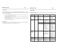
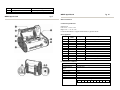
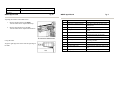
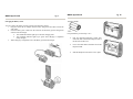
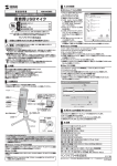
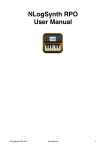
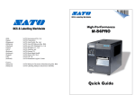
EXCELLENT PRINTING
PERFORMANCE
(HQ)
(Japan)
(Singapore)
(Malaysia)
(Thailand)
(China)
(USA)
(Belgium)
(Germany)
(Poland)
(UK)
(Holland)
SATO International Pte. Ltd.
SATO Corporation
SATO Asia Pacific Pte. Ltd.
SATO Auto-ID Malaysia Sdn. Bhd.
SATO Auto-ID (Thailand) Co., Ltd
SATO Shanghai Co., Ltd
SATO America, Inc.
SATO Europe NV
SATO Deutchland GmbH
SATO Polska SP Z O.O.
SATO UK Ltd
SATO Rotterdam Logistics Center
Factory :
(Malaysia)
(Malaysia)
SATO Malaysia Electronics Manufacturing Sdn. Bhd.
SATO Labelling Malaysia Electronics Sdn.Bhd.
MB400
Quick Guide
SAP/MB400/QG/Jan05/02
MB400 Quick Guide
Pg 20
Options
SATO Asia Pacific Pte. Ltd.
438A Alexandra Road
#05-01/02 Alexandra Technopark
Singapore 119967
Tel : (65) 6271 5300; Fax : (65) 6273 6011
Sales Hotline : (65) 6276 2722; Service Hotline : (65) 6273 6455
Email : [email protected]
Website : www.satoworldwide.com
© Copyright 2003
SATO Asia Pacific Pte. Ltd.
Warning : This equipment complies with the requirements in Part 15 of FCC rules for a Class
A computing device. Operation of this equipment in a residential area may cause
unacceptable interference to radio and TV reception requiring the operator to take whatever
steps necessary to correct the interference.
All rights reserved. No part of this document may be reproduced or issued to third parties in
any form whatsoever without the express permission of SATO Asia Pacific Pte. Ltd. The
materials in this document are provided for general information and are subject to change
without notice. SATO Asia Pacific Pte. Ltd. assumes no responsibilities for any errors that
may appear.
SAP/MB400/QG/Jan05/02
Battery Pack
Used when the printer is carried
Battery Charger
The battery packs are recharged on this.
AC Adapter for Printer
Use the adapter to supply power from a household electrical outlet (AC 100V). Connect the
DC output jack of the adapter to the printer.
RS232C Cable
For connection of computers and handy terminals.
Weak Radio Unit
For communication with specified handy terminals.
Battery Charger Set
Battery charger enables the recharging of the maximum of 4 batteries at the same time, with
one AC adapter.
MB400 Quick Guide
Item
Label Sensor
Font
Barcode
Two Dimension Code
Function Key
LED
Noise Gauge
Protection Function
Environment Conditions
(including battery)
Option
Pg 19
Details
Opaque sensor / Dispense sensor
SATO standard font: x 21, x 22, x 23
Kanji 16 x 16, 24 x 24 Kaku Gothic / Mincho (JIS
First Second standard)
JAN8/13, UPC-E/UPC-A, NW-7, CODE39,
INTERLEAVED 2 of 5, CODE 128, CODE 93,
Customer Bar Code
PDF 417, QR code
POWER key, PRINT key, FEED key
STATUS, BATTERY (Red / Orange / Green)
Noise radiation: VCCI - B
Static withstanding pressure: Level 2
Suspension of action upon detection of low batteries
Operation temperature: 0 - 50ºC
Humidity: 25-80% (without condensation)
Storage Temperature: -10 - 60ºC
Humidity: 25-80% (without condensation)
AC Adapter, Battery charger, Battery pack, RS-232C
cable
MB400 Quick Guide
PRINTER OVERVIEW
The SATO MB400 printer has a compact and lightweight body combined with
high performances. Not only does this printer print barcodes clearly, it can
also enlarge and print various types of fonts and Kanji characters in a free
layout.
The Operator’s Manual will help you to understand the basic operations of the
printer such as setup, installation, configuration, cleaning and maintenance.
MB400 is superb in durability, as it has been designed with the premises of
printing barcodes. Special considerations have also been taken so that the
printer can be easily maintained.
As a portable printer, MB400 can easily print and dispense labels to enable the
application of labels on-site.
This Quick Guide is an extract of the more common functions which you need
to start the printer running. For more advanced functions, please refer to the
Operator’s Manual
MB400 Quick Guide
Pg 1
Table of Contents
Installation …………………………………………………………………….
Installation …………………………………………………………...
Other Accessories ……………………………………………………
Considerations ……………………………………………………….
Components ………………………………………………………….
Pg 18
MB400 Specifications
2
2
2
3
4
Battery Pack ………………………………………………………………….. 7
Charging the Battery Pack …………………………………………… 7
Installing and Removing Battery Pack ………………………………. 9
Media Loading ………………………………………………………………..
Setting Labels ………………………………………………………...
Adjusting the Position of the Label Sensor …………………………..
MB400 Quick Guide
10
10
13
RS232 Connection …………………………………………………………….. 14
Item
Printing Method
Head Density
Maximum Printing Size
Printing Speed
Printing mode
Size
Weight
Power (Battery)
Paper
Label Shape
Label Size
Troubleshooting ……………………………………………………………….. 15
MB400 Specifications …………………………………………………………. 18
Thickness
Options ………………………………………………………………………… 20
Self Diagnosing Function
Power Save Function
Interface
RS232C/TTL
Optical
Coupler
Details
Thermal
8 dots/mm
Width 104mm x Pitch 297mm
Max. 50mm/sec. (may vary from environment)
Continuous, Dispense and Journal
Printer : W190mm x D80mm x H139mm
Approximately 960g (including battery)
Packet type (Lithium ion battery) : 1600mAh; Will
print 1 roll of journal paper (25m) on continuous
mode when fully charged (printing rate at 15% or
less)
Always use specified labels
Roll; Maximum outer diameter: 58mm
Width: 50-11mm (53-114mm)
Pitch (Continuous): 25-297mm (28-300mm)
Pitch (Dispense): 25-182mm (28-185mm)
Numbers indicated in ( ) are for pasteboards, nonadhesive or non-separated labels and journal paper.
Continuous: 0.06 - 0.18mm
Dispense: 0.18mm (the thickness of the pasteboard
is under 0.06mm)
Battery Check / Paper end
Head Open / Test Printing / Head Check
In Sleep mode after 5 seconds without any
operation, and Auto Power Off mode after 5
minutes without any operation.
High density special connector
IrDA (IrDA Standard Ver. 1.2 compliant)
MB400 Quick Guide
Status
(LED)
Green
(blinking)
Red
(blinking)
Mode
Pg 17
Details
On-Line
(Printing
/Receiving
data)
Buffer near full
All Modes
Low Battery
Cause
Approaching the
buffer quota
Batteries are not
recharged
properly.
Solution
Pause the data
transmission
and wait till the
buffer is empty
before trying
again.
Recharge the
batteries.
MB400 Quick Guide
Pg 2
Installation
Remove the MB400 from its packing container. Check to make sure you have the following
items:
Shoulder belt
The power will automatically be turned off 30 seconds after “Low Battery” is indicated. Make
sure the power is off before removing the battery pack and recharge the battery.
Printer
Quick Guide
Battery pack
* The shape of the protector
pads to hold the printer in place
may differ from the picture
shown.
Other Accessories
• Cable Lock - Attached to the interface connector.
•
Adjustment Screwdriver - Located inside the printer (under
the label feed area).
MB400 Quick Guide
Pg 3
Considerations
Careful considerations must be given when selecting location of the printer, especially to
environmental considerations. To obtain optimum results from MB400, always try to avoid
operation locations influenced by:
•
•
•
Direct or bright sunlight, as this will make the label sensor less responsive and may
cause the label to be sensed incorrectly.
Locations which have extreme temperatures, as this can create electrical problems on
the circuits in the printer.
The installed location of the printer should ideally be in areas free from dust,
humidity and sudden vibrations.
MB400 Quick Guide
Pg 16
Troubleshooting
The status of the printer is shown on the status indicator. To solve the problems, follow the
instructions in the table.
Status
(LED)
Red
Red
(blinking)
Mode
After
power
input
On-Line
Consumables
Always use SATO recommended labels in MB400 printer. The use of incorrect material may
cause malfunctions of the printer and void the printer warranty.
Details
1. Program
error
2. FLASH
ROM error
Open cover
Paper end
Sensor error
Cause
Solution
FLASH ROM
reading/writing error
1. Replace the
substrate
2. Adjust the
program again
1. Lock the
cover.
2. Adjust the
micro switch.
Set new labels
1. Adjust the
sensor level.
2. Adjust the
sensor type.
3. Reset the
labels properly.
4. Adjust the
position of the
sensor.
1. Adjust the
data amount at
the host side so
that it won’t
exceed the
buffering quota.
2. Match the
protocol.
Replace the
print head
The function
will deactivate
when the print
1. Cover isn’t locked.
2. Cover micro
switch is not working
properly.
Out of paper
1. Sensor level isn’t
accurate.
2. Sensor type
doesn’t match.
3. Label is
meandering.
4. Sensor position
isn’t accurate.
Red/
Orange
(blinking)
On-Line
Buffer over
1. Received data over
the buffer quota.
2. The protocol
between the printer
and host does not
match.
Orange
(blinking)
Orange/
Green
(blinking)
On-Line
Print Head error
On-Line
Head
overheating
protection
The print head is
damaged
Not an error. The
overheating
protection function
function
activates when the
print head
temperature rises
above 70ºC.
head
temperature
goes down to
60ºC.
MB400 Quick Guide
Pg 15
MB400 Quick Guide
Pg 4
Components
ACK/NAK Control Type
This communication protocol is a software handshake type based on ACK/NAK.
When the print data (STX-ETX) is sent from the host under the following conditions, the
received data is not guaranteed.
1. When the printer is in the offline condition.
2. When an error occurs with the printer.
Wiring
Host
RD
SD
SG
CS
RS
Printer
11 SD
10 RD
12 SG
POWER Key
PRINT Key
FEED Key
STATUS LED Indicator
BATTERY LED Indicator
Turns the power on and off.
Sets the printer to on-line or off-line.
Feeds labels.
Indicates the status of the printer.
Indicates the status of the battery.
* For SG, 1, 7 pins are available in addition to 12 pin
*Note
For writing, some host types are required to loop CS and RS on the host side (always keep CS
and RS “High”). Therefore, you must confirm the host type before connecting.
Input and Output Signal
Pin No.
11
Signal Name
SD
Direction
Output
10
RD
Input
1, 7 or 12
SG
-
Description
The data transferred from the printer to the
host.
The data transferred from the host to the
printer.
Signal ground
No.
1
Item
Dispense/Continuous switch lever
2
Dispenser unit
3
4
5
Front cover Open/Close lever
Front cover
Easy cutter
Details
Switches the print mode
(dispense/continuous)
Move this when the Dispense mode
is selected
Opens and closes the front cover
Open this for setting labels
Cuts printed labels
6
7
8
Battery cover
Label ejection
Platen Roller
MB400 Quick Guide
Insertion of battery pack
Collection point for printed labels
Pg 5
MB400 Quick Guide
Pg 14
RS232 Connection
Connection Specification
Signal Level:
Low Level → -3V to -12V
High Level → +3V to +12V
Connector Manufacturer: Nippon Kouku Denshi, Type RL01-R12P
Pin Assignments
Pin No
Signal
Name
1
SG
2
3
4
5
6
7
SG
8
9
10
RD
11
SD
12
SG
Type
Description
Input
Output
-
Signal Ground
Not Used
Not Used
Not Used
Not Used
Not Used
Signal Ground
Not Used
Not Used
Receiving Data
Sending Data
Signal Ground
Communication Conditions
Item
Details
Protocol
ACK/NAK Control Type
Communication
Asynchronous
Type
Baud Rate (bps)
4800, 9600, 19200, 38400
Data Length
8 bits
Stop Bit
1 bit
Parity Bit
NONE, EVEN, ODD
Codes Used
ASCII Character Codes, JIS Kanji Codes
Transfer Format
LSB (Low level bit leading)
Start b0 b1 b2 b3 b4 b5 b6
b7
Stop
Control Code
Error Control
Method
MB400 Quick Guide
STX (02H), ETX (03H), ACK (06H), NAK (15H)
Response Check
Pg 13
MB400 Quick Guide
Pg 6
Adjusting the Position of the Label Sensor
1.
Moving the label Sensor to the Right.
Turn the Label Sensor Adjustment Dial up.
No.
1
2
Items
Label sensor
Label sensor adjustment dial
2.
Moving the Label Sensor to the Left.
Turn the Label Sensor Adjustment Dial down.
3
4
Label guide
O ring
5
Shoulder belt hook
6
7
8
Adjustment screwdriver
IrDA filter
IrDA adjustment lever
9
10
11
Interface cover
Interface connector (RS232C)
DC input jack cover
12
DC input jack
Using the Sensor
Align the right edge of the sensor with the right edge of
the label.
Details
Adjust this to the label size used
Use this to adjust the location of the
label sensor
Adjust this to the label size used.
Use this ring when fixing the label
guide
Attaches the shoulder belt when
hanging the printer on shoulder.
(Supplied accessory)
Location of IrDA receiving element
Changes the angle of the IrDA
receiving element.
Covers the interface connector
Connects to a computer
Covers the DC input jack when not in
use
Connects the AC adapter
MB400 Quick Guide
Pg 7
Charging the Battery Pack
You can recharge the battery pack by inserting into the battery charger.
1. Plug one end of the AC adapter into the battery charger and the other end into the
wall outlet.
2. Insert the battery pack. Make sure the connector on the battery pack is facing down
and insert into the charger.
• The CHARGE indicator lights up in red when charging starts.
• The CHARGE indicator lights up in green when charging is completed.
(Fully charged)
3. When charging is completed, remove the battery pack from the charger.
MB400 Quick Guide
[Dispense Mode]
First perform the previous Steps 1 to 6.
•
Pick the Dispense/Continuous switch lever
from both sides and slide the Dispenser unit to
the direction of the arrow.
•
Leave more than 30mm of the label out for the
Dispense mode.
•
Slide the Dispenser unit until it is set in place.
Pg 12
MB400 Quick Guide
4.
Pg 11
MB400 Quick Guide
Insert the label roll on the label guide boss inside
the front cover.
*Note
•
Press the tab to adjust the label guide (right), and
adjust the guide to the width of the labels used.
•
•
Label guide boss
Firmly insert the label roll on the bosses on the left
and right of the label guide.
•
Move the label roll to make sure that it is firmly
set on the bosses.
•
5.
6.
After peeling the lead tape on the roll, take the
leading edge of the first label on the roll and pull it
out via the platen roller. Then turn the front cover
in the direction of the arrow.
Close the front cover in the direction of the arrow.
Press the front cover until the cover Open/Close
lever clicks.
Pg 8
If the CHARGE indicator on the charger does not light up, make sure that the battery
pack is firmly attached to the charger. The battery might not be able to charge if it is
not firmly attached.
If an already charged battery pack is inserted into the charger, the CHARGE indicator
will turn red once (charging), however, it will soon change to green (fully charged).
If charging a battery pack that has not been used for a long period, the HCARGE
indicator will flash for a while. This does not indicate an error, and you can continue
charging as it is. It the indicator continues to flash for a long time while charging,
replace the battery pack with a new one.
The battery pack can be charged up to 300 times (during usage in regular
temperature). If the battery pack is fully charged but soon runs out, replace the
battery pack with a new one.
* Take down the date of purchase of the battery with a marker on the sticker
attached to the battery pack as a guideline of the number of times the battery can be
recharged (the life of the battery). For example, Date of purchase: 1/9/2002.
The battery pack cannot be used when using the AC adapter. If the AC adapter jack
is plugged into the printer when using the battery, the power will be reset. If there
are any remaining print data, they will be lost.
Charging Time.
The charger time for one battery pack from empty until fully charged is about 90 minutes. For
two battery packs, it takes about 130 minutes. The charging time varies depending on the
environment.
MB400 Quick Guide
Pg 9
MB400 Quick Guide
Installing and Removing Battery Pack
Media Loading
Remove the protection case.
Setting Labels
The method of setting labels may vary depending on the print mode.
1.
Place your finger on the battery cover ribbed
area, and open the battery cover in the
direction of the arrow.
2.
Insert the battery pack with the connector
facing towards the end.
* Insert the battery all the way in until the
lock clicks into place.
3.
To remove the battery pack, press down the
lock lever and release the lock. Then pull the
battery pack out placing your finger into the
notch.
** Take caution not to drop the battery pack when
removing it. The battery pack may be damaged if it
is dropped.
Battery Status
1. Battery near end
When the battery is getting low, the battery
near end is detected and the BATTERY
LED indicator lights up in orange. The keys
can still be operated, however the battery
should be recharged.
2. Low Battery Error
When the battery is empty, a low battery error is detected and the BATTERY
LED indicator lights up in red. The keys cannot be operated, and after 30 seconds
the power automatically turns off. Make sure to recharge the battery.
Status
Battery near end
Low battery error
BATTERY LED indicator
Light (orange)
Light (red)
** The BATTERY LED indicator does not light up during printing or an error, even if
battery near end or low battery error has been detected.
[Continuous Mode]
1.
Press the cover Open/Close lever in the
direction of the arrow to release the front
cover lock.
2.
Slide the front cover to open. Hold the
front cover and slide it in the direction of
the arrow until it stops.
3.
Open the front cover in the direction of the
arrow.
Pg 10