1
Special Topics Guide—Sensor High Availability
revision 1.0
McAfee® Network Security Platform
Network Security Sensor
version 6.0
McAfee®
Network Protection
Industry-leading network security solutions
COPYRIGHT
Copyright ® 2001 - 2009 McAfee, Inc. All Rights Reserved. No part of this publication may be reproduced, transmitted, transcribed, stored in a retrieval system, or translated into
any language in any form or by any means without the written permission of McAfee, Inc., or its suppliers or affiliate companies.
TRADEMARKS
ACTIVE FIREWALL, ACTIVE SECURITY, ACTIVESECURITY (AND IN KATAKANA), ACTIVESHIELD, CLEAN-UP, DESIGN (STYLIZED E), DESIGN (STYLIZED N),
ENTERCEPT, EPOLICY ORCHESTRATOR, FIRST AID, FOUNDSTONE, GROUPSHIELD, GROUPSHIELD (AND IN KATAKANA), INTRUSHIELD, INTRUSION PREVENTION
THROUGH INNOVATION, McAfee, McAfee (AND IN KATAKANA), McAfee AND DESIGN, McAfee.COM, McAfee VIRUSSCAN, NET TOOLS, NET TOOLS (AND IN KATAKANA),
NETSCAN, NETSHIELD, NUTS & BOLTS, OIL CHANGE, PRIMESUPPORT, SPAMKILLER, THREATSCAN, TOTAL VIRUS DEFENSE, VIREX, VIRUS FORUM, VIRUSCAN,
VIRUSSCAN, VIRUSSCAN (AND IN KATAKANA), WEBSCAN, WEBSHIELD, WEBSHIELD (AND IN KATAKANA) are registered trademarks or trademarks of McAfee, Inc. and/or
its affiliates in the US and/or other countries. The color red in connection with security is distinctive of McAfee brand products. All other registered and unregistered trademarks
herein are the sole property of their respective owners.
LICENSE AND PATENT INFORMATION
License Agreement
NOTICE TO ALL USERS: CAREFULLY READ THE APPROPRIATE LEGAL AGREEMENT CORRESPONDING TO THE LICENSE YOU PURCHASED, WHICH SETS FORTH
THE GENERAL TERMS AND CONDITIONS FOR THE USE OF THE LICENSED SOFTWARE. IF YOU DO NOT KNOW WHICH TYPE OF LICENSE YOU HAVE ACQUIRED,
PLEASE CONSULT THE SALES AND OTHER RELATED LICENSE GRANT OR PURCHASE ORDER DOCUMENTS THAT ACCOMPANIES YOUR SOFTWARE PACKAGING
OR THAT YOU HAVE RECEIVED SEPARATELY AS PART OF THE PURCHASE (AS A BOOKLET, A FILE ON THE PRODUCT CD, OR A FILE AVAILABLE ON THE WEB SITE
FROM WHICH YOU DOWNLOADED THE SOFTWARE PACKAGE). IF YOU DO NOT AGREE TO ALL OF THE TERMS SET FORTH IN THE AGREEMENT, DO NOT INSTALL
THE SOFTWARE. IF APPLICABLE, YOU MAY RETURN THE PRODUCT TO McAfee OR THE PLACE OF PURCHASE FOR A FULL REFUND.
License Attributions
This product includes or may include:
* Software developed by the OpenSSL Project for use in the OpenSSL Toolkit (http://www.openssl.org/). * Cryptographic software written by Eric A. Young and software written by
Tim J. Hudson. * Some software programs that are licensed (or sublicensed) to the user under the GNU General Public License (GPL) or other similar Free Software licenses
which, among other rights, permit the user to copy, modify and redistribute certain programs, or portions thereof, and have access to the source code. The GPL requires that for
any software covered under the GPL, which is distributed to someone in an executable binary format, that the source code also be made available to those users. For any such
software covered under the GPL, the source code is made available on this CD. If any Free Software licenses require that McAfee provide rights to use, copy or modify a software
program that are broader than the rights granted in this agreement, then such rights shall take precedence over the rights and restrictions herein. * Software originally written by
Henry Spencer, Copyright 1992, 1993, 1994, 1997 Henry Spencer. * Software originally written by Robert Nordier, Copyright (C) 1996-7 Robert Nordier. * Software written by
Douglas W. Sauder. * Software developed by the Apache Software Foundation (http://www.apache.org/). A copy of the license agreement for this software can be found at
www.apache.org/licenses/LICENSE-2.0.txt. * International Components for Unicode ("ICU") Copyright (C) 1995-2002 International Business Machines Corporation and others. *
Software developed by CrystalClear Software, Inc., Copyright (C) 2000 CrystalClear Software, Inc. * FEAD(R) Optimizer(R) technology, Copyright Netopsystems AG, Berlin,
Germany. * Outside In(R) Viewer Technology (C) 1992-2001 Stellent Chicago, Inc. and/or Outside In(R) HTML Export, (C) 2001 Stellent Chicago, Inc. * Software copyrighted by
Thai Open Source Software Center Ltd. and Clark Cooper, (C) 1998, 1999, 2000. * Software copyrighted by Expat maintainers. * Software copyrighted by The Regents of the
University of California, (C) 1996, 1989, 1998-2000. * Software copyrighted by Gunnar Ritter. * Software copyrighted by Sun Microsystems, Inc., 4150 Network Circle, Santa Clara,
California 95054, U.S.A., (C) 2003. * Software copyrighted by Gisle Aas. (C) 1995-2003. * Software copyrighted by Michael A. Chase, (C) 1999-2000. * Software copyrighted by
Neil Winton, (C) 1995-1996. * Software copyrighted by RSA Data Security, Inc., (C) 1990-1992. * Software copyrighted by Sean M. Burke, (C) 1999, 2000. * Software copyrighted
by Martijn Koster, (C) 1995. * Software copyrighted by Brad Appleton, (C) 1996-1999. * Software copyrighted by Michael G. Schwern, (C) 2001. * Software copyrighted by Graham
Barr, (C) 1998. * Software copyrighted by Larry Wall and Clark Cooper, (C) 1998-2000. * Software copyrighted by Frodo Looijaard, (C) 1997. * Software copyrighted by the Python
Software Foundation, Copyright (C) 2001, 2002, 2003. A copy of the license agreement for this software can be found at www.python.org. * Software copyrighted by Beman
Dawes, (C) 1994-1999, 2002. * Software written by Andrew Lumsdaine, Lie-Quan Lee, Jeremy G. Siek (C) 1997-2000 University of Notre Dame. * Software copyrighted by Simone
Bordet & Marco Cravero, (C) 2002. * Software copyrighted by Stephen Purcell, (C) 2001. * Software developed by the Indiana University Extreme! Lab
(http://www.extreme.indiana.edu/). * Software copyrighted by International Business Machines Corporation and others, (C) 1995-2003. * Software developed by the University of
California, Berkeley and its contributors. * Software developed by Ralf S. Engelschall <[email protected]> for use in the mod_ssl project (http:// www.modssl.org/). * Software
copyrighted by Kevlin Henney, (C) 2000-2002. * Software copyrighted by Peter Dimov and Multi Media Ltd. (C) 2001, 2002. * Software copyrighted by David Abrahams, (C) 2001,
2002. See http://www.boost.org/libs/bind/bind.html for documentation. * Software copyrighted by Steve Cleary, Beman Dawes, Howard Hinnant & John Maddock, (C) 2000. *
Software copyrighted by Boost.org, (C) 1999-2002. * Software copyrighted by Nicolai M. Josuttis, (C) 1999. * Software copyrighted by Jeremy Siek, (C) 1999-2001. * Software
copyrighted by Daryle Walker, (C) 2001. * Software copyrighted by Chuck Allison and Jeremy Siek, (C) 2001, 2002. * Software copyrighted by Samuel Krempp, (C) 2001. See
http://www.boost.org for updates, documentation, and revision history. * Software copyrighted by Doug Gregor ([email protected]), (C) 2001, 2002. * Software copyrighted by
Cadenza New Zealand Ltd., (C) 2000. * Software copyrighted by Jens Maurer, (C) 2000, 2001. * Software copyrighted by Jaakko Järvi ([email protected]), (C) 1999, 2000. *
Software copyrighted by Ronald Garcia, (C) 2002. * Software copyrighted by David Abrahams, Jeremy Siek, and Daryle Walker, (C) 1999-2001. * Software copyrighted by Stephen
Cleary ([email protected]), (C) 2000. * Software copyrighted by Housemarque Oy <http://www.housemarque.com>, (C) 2001. * Software copyrighted by Paul Moore, (C)
1999. * Software copyrighted by Dr. John Maddock, (C) 1998-2002. * Software copyrighted by Greg Colvin and Beman Dawes, (C) 1998, 1999. * Software copyrighted by Peter
Dimov, (C) 2001, 2002. * Software copyrighted by Jeremy Siek and John R. Bandela, (C) 2001. * Software copyrighted by Joerg Walter and Mathias Koch, (C) 2000-2002. *
Software copyrighted by Carnegie Mellon University (C) 1989, 1991, 1992. * Software copyrighted by Cambridge Broadband Ltd., (C) 2001-2003. * Software copyrighted by
Sparta, Inc., (C) 2003-2004. * Software copyrighted by Cisco, Inc and Information Network Center of Beijing University of Posts and Telecommunications, (C) 2004. * Software
copyrighted by Simon Josefsson, (C) 2003. * Software copyrighted by Thomas Jacob, (C) 2003-2004. * Software copyrighted by Advanced Software Engineering Limited, (C)
2004. * Software copyrighted by Todd C. Miller, (C) 1998. * Software copyrighted by The Regents of the University of California, (C) 1990, 1993, with code derived from software
contributed to Berkeley by Chris Torek.
Issued DECEMBER 2009 / Special Topics Guide—Sensor High Availability
700-2382-00/ 1.0 - English
Contents
Preface ........................................................................................................... v
Introducing McAfee Network Security Platform............................................................................. v
About the Guide ............................................................................................................................ v
Conventions used in this guide ..................................................................................................... v
Related documentation .................................................................................................................vi
Contacting Technical Support ......................................................................................................vii
Chapter 1 Background.................................................................................. 1
Chapter 2 Network Security Platform Failover Architecture .................... 2
Chapter 3 Sensor Failover Implementation................................................ 3
Chapter 4 Understanding the current network topology .......................... 4
Two paths - Active/Passive ........................................................................................................... 4
Two paths - Active/Active .............................................................................................................. 4
A single path.................................................................................................................................. 5
Chapter 5 Determining optimal Sensor location........................................ 6
Redundant Sensors on a single path ............................................................................................ 8
Preventing duplicate alerts .......................................................................................................... 10
Summary ..................................................................................................................................... 10
Chapter 6 Configuring the ports on each Sensor.................................... 11
Potential pitfall ............................................................................................................................. 12
A note on fail open functionality for GE ports .............................................................................. 12
A caution about active-passive failover ....................................................................................... 13
Chapter 7 How dongles work..................................................................... 14
Chapter 8 Physically installing the Sensors ............................................ 18
Reality check - Asymmetric routing ............................................................................................. 21
Chapter 9 Defining the Network Security Platform Failover Pair........... 22
Chapter 10 Cabling the heartbeat connection ......................................... 25
Initial hints ................................................................................................................................... 25
GBIC cabling ............................................................................................................................... 26
Important notes ....................................................................................................................27
Cabling guidelines and examples................................................................................................ 27
I-1200 and I-1400 examples ................................................................................................27
I-2700 examples...................................................................................................................27
I-4000 example ....................................................................................................................28
I-3000 and I-4010 examples ................................................................................................28
TX GBICs .................................................................................................................................... 28
Cabling failover through a network device .................................................................................. 29
Chapter 11 Verifying the failover configuration....................................... 30
iii
Confirming Sensor communication ............................................................................................. 30
Testing failover setup .................................................................................................................. 31
Chapter 12 Network Scenarios for Sensor High Availability.................. 33
I-4010 Sensor in Load balanced Configuration ........................................................................... 33
I-4010 Sensor in Active/Active HA mode .................................................................................... 33
I-4010 Sensor in Active/Passive HA mode.................................................................................. 34
Index ............................................................................................................. 35
iv
Preface
This preface provides a brief introduction to the product, discusses the information in this
document, and explains how this document is organized. It also provides information such
as, the supporting documents for this guide and how to contact McAfee Technical Support.
Introducing McAfee Network Security Platform
McAfee® Network Security Platform [formerly McAfee® IntruShield®] delivers the most
comprehensive, accurate, and scalable Network Access Control (NAC), network Intrusion
Prevention System (IPS) and Network Threat Behavior Analysis (NTBA) for mission-critical
enterprise, carrier, and service provider networks, while providing unmatched protection
against spyware and known, zero-day, and encrypted attacks.
McAfee Network Threat Behavior Analysis Appliance provides the capability of monitoring
network traffic by analyzing NetFlow information flowing through the network in real time,
thus complementing the NAC and IPS capabilities in a scenario in which McAfee Network
Security Sensor, NAC Sensor, and NTBA Appliance are installed and managed through a
single Manager.
About the Guide
This special topics guide helps you to deploy McAfee Network Security Sensor (Sensor)s
as failover pairs. The guide provides detailed sections on determining optimal Sensor
location, configuring Sensor ports, defining failover pairs, cabling and verifying the failover
connection.
Conventions used in this guide
This document uses the following typographical conventions:
Convention
Example
Terms that identify fields, buttons, tabs,
options, selections, and commands on the
User Interface (UI) are shown in Arial Narrow
bold font.
The Service field on the Properties tab specifies the
name of the requested service.
Menu or action group selections are
indicated using a right angle bracket.
Select My Company > Admin Domain > Summary.
Procedures are presented as a series of
numbered steps.
1. On the Configuration tab, click Backup.
v
McAfee® Network Security Platform 6.0
Preface
Convention
Example
Names of keys on the keyboard are denoted Press ENTER.
using UPPER CASE.
Text such as syntax, key words, and values
that you must type exactly are denoted
using Courier New font.
Type: setup and then press ENTER.
Variable information that you must type
based on your specific situation or
environment is shown in italics.
Type: Sensor-IP-address and then press
ENTER.
Parameters that you must supply are shown
enclosed in angle brackets.
set Sensor ip <A.B.C.D>
Information that you must read before
beginning a procedure or that alerts you to
negative consequences of certain actions,
such as loss of data is denoted using this
notation.
Caution:
Warning:
Information that you must read to prevent
injury, accidents from contact with electricity,
or other serious consequences is denoted
using this notation.
Notes that provide related, but non-critical,
information are denoted using this notation.
Note:
Related documentation
The following documents and on-line help are companions to this guide. Refer to Quick
Tour for more information on these guides
•
•
•
•
•
•
•
•
•
•
•
•
•
•
•
•
•
Quick Tour
Installation Guide
Upgrade Guide
Getting Started Guide
IPS Deployment Guide
Manager Configuration Basics Guide
I-1200 Sensor Product Guide
I-1400 Sensor Product Guide
I-2700 Sensor Product Guide
I-3000 Sensor Product Guide
I-4000 Sensor Product Guide
I-4010 Sensor Product Guide
M-1250/M-1450 Sensor Product Guide
M-1250/M-1450 Quick Start Guide
M-2750 Sensor Product Guide
M-2750 Quick Start Guide
M-3050/M-4050 Sensor Product Guide
vi
McAfee® Network Security Platform 6.0
•
•
•
•
•
•
•
•
•
•
•
•
•
•
•
•
•
•
•
•
•
•
•
•
•
•
•
•
•
•
•
Preface
M-3050/M-4050 Quick Start Guide
M-6050 Sensor Product Guide
M-6050 Quick Start Guide
M-8000 Sensor Product Guide
M-8000 Quick Start Guide
Gigabit Optical Fail-Open Bypass Kit Guide
Gigabit Copper Fail-Open Bypass Kit Guide
10 Gigabit Fail-Open Bypass Kit Guide
M-8000/M-6050/M-4050/M-3050 Slide Rail Assembly Procedure
M-2750 Slide Rail Assembly Procedure
M-series DC Power Supply Installation Procedure
Administrative Domain Configuration Guide
Manager Server Configuration Guide
CLI Guide
Device Configuration Guide
IPS Configuration Guide
NAC Configuration Guide
Integration Guide
System Status Monitoring Guide
Reports Guide
Custom Attack Definitions Guide
Central Manager Administrator's Guide
Best Practices Guide
Troubleshooting Guide
Special Topics Guide—In-line Sensor Deployment
Special Topics Guide—Virtualization
Special Topics Guide—Denial-of-Service
NTBA Appliance Administrator's Guide
NTBA Monitoring Guide
NTBA Appliance T-200 Quick Start Guide
NTBA Appliance T-500 Quick Start Guide
Contacting Technical Support
If you have any questions, contact McAfee for assistance:
Online
Contact McAfee Technical Support http://mysupport.mcafee.com.
Registered customers can obtain up-to-date documentation, technical bulletins, and quick
tips on McAfee's 24x7 comprehensive KnowledgeBase. In addition, customers can also
resolve technical issues with the online case submit, software downloads, and signature
updates.
vii
McAfee® Network Security Platform 6.0
Preface
Phone
Technical Support is available 7:00 A.M. to 5:00 P.M. PST Monday-Friday. Extended 24x7
Technical Support is available for customers with Gold or Platinum service contracts.
Global phone contact numbers can be found at McAfee Contact Information
http://www.mcafee.com/us/about/contact/index.html page.
Note: McAfee requires that you provide your GRANT ID and the serial number of
your system when opening a ticket with Technical Support. You will be provided with
a user name and password for the online case submission.
viii
CHAPTER 1
Background
Most networks today have some amount of in-built redundancy. However, the extent to
which a network can withstand a failure varies, depending on the environment. For
example, one setup might have two fully redundant paths to and from the Internet,
whereas another might have Primary and Secondary firewalls, but single points of failure
elsewhere.
Network devices traditionally provide redundancy at Layer 2 or 3 of the OSI model. That is,
they take advantage of the existing switching or routing infrastructure to provide fault
tolerance.
The principle behind Hot Standby Router Protocol (HSRP - RFC 2281) and Virtual Router
Redundancy Protocol (VRRP - RFC 2338), for example, is that two or more routers share
a Virtual IP (VIP) address. One router takes on a primary role and “owns” the VIP; all traffic
directed to the VIP routes through the primary when all is well. If the primary goes offline, a
standby router is automatically promoted and takes over ownership.
Because most network devices run at Layer 2 or higher, incorporating redundancy often
requires a logical topology change. As a simple example, to add the aforementioned router
redundancy, you have to reconfigure all downstream routers to use with the new VIP as
their default gateway.
1
CHAPTER 2
Network Security Platform Failover Architecture
McAfee® Network Security Platform was built with high availability in mind. In fact, those
who initially become confused by the possibilities around McAfee Network Security
Platform failover usually do so because the implementation is actually simpler than they
assume initially.
Note the following points regarding Network Security Platform failover architecture:
•
Sensors are invisible at Layer 2 and above; the monitoring ports do not even have
MAC addresses.
•
Sensors configured for failover confirm a “heartbeat” once each second.
•
Sensors configured for failover share flow information in real time.
As a result, you do not have to worry about Layer 2 and 3 topology changes when you
introduce Network Security Platform failover into the environment; and in the unlikely event
of a Sensor failure, failover is instantaneous and connection state is maintained.
2
CHAPTER 3
Sensor Failover Implementation
A typical McAfee® Network Security Platform failover implementation includes the following
steps:
•
Understanding the current network topology
•
Determining optimal Sensor location
•
Configuring the ports on each Sensor
•
Physically installing the Sensors
•
Defining McAfee Network Security Platform failover Pair
•
Cabling the heartbeat connection
•
Verifying the failover configuration
In the sections that follow, we will consider each of these points in detail.
3
CHAPTER 4
Understanding the current network topology
Understanding the current network topology is essential for the proper planning of McAfee®
Network Security Platform failover solution. Rather, the more you understand about the
existing data flow, the less likely you run into obstacles during implementation.
The most common network topologies can be summarized as follows:
•
•
•
Two paths - Active/Passive
Two paths - Active/Active
A single path
Note: For usage scenarios regarding active/passive and active/active network
topologies, see the section Network Scenarios for Sensor High Availability (on page
33).
Two paths - Active/Passive
Most redundant links today are made up of active and passive paths. There are two ways
in and out of the network, but only one way will actually be available at any given time. The
path passing traffic is called the active path, and the one standing by in the event of a
failure is called the passive path.
HSRP, VRRP, Spanning Tree Protocol (STP), and Dynamic Routing Protocols, such as,
OSPF, EIGRP, and BGP, are arguably the most common technologies used to automate
network failover. Admittedly, many of these include options to balance traffic, but they are
historically configured to allow for one path to pass traffic at a time.
Two paths - Active/Active
Some networks will maintain two active paths to and from the Internet. In addition to
redundancy, these approaches can potentially double the available bandwidth, under
normal conditions.
In most cases, the two paths are not designed to share traffic unless there is a failure.
When all is well, a flow will be established on one of the paths, and all packets from that
flow will traverse the same path.
In some cases, however, the network infrastructure is designed in such a way that cross
both paths under normal circumstances. For example, inbound requests might come in on
path A and outbound responses might go out on path B. Such traffic is said to be
asymmetrically routed.
Of course, if one path becomes unavailable, all traffic will be routed across the remaining
path.
4
McAfee® Network Security Platform 6.0
Understanding the current network topology
A single path
Some networks do not include much or any redundancy. In this case, there is one or more
single points of failure.
If one of the non-redundant devices fails, the connection to the Internet will fail as well.
Most companies that choose to invest in a redundant Network Security Platform solution
also invest in redundant paths to and from their network. That is, there are numerous
companies that have single points of failure, but insist on implementing Network Security
Platform failover.
5
CHAPTER 5
Determining optimal Sensor location
The previous section is mostly intended as a point of reference. The good news is that
McAfee® Network Security Platform failover process is often identical, whether the network
failover configuration is active-active, with or without asymmetric routing, active-passive, or
even made up of a single path.
The details are as follows:
•
•
•
Both McAfee® Network Security Sensors (Sensors) in a failover Pair are always in an
active state. In this way, they are sure to protect a network on which the redundant
path is active.
However, such an approach does not preclude the Sensors from protecting a network
on which the Secondary path is passive; the Sensor on the passive path will not have
much or any flow information to pass to its counterpart.
Sensors in a failover Pair scan independently, but use the information they share with
each other during the scanning process. In this way, if a flow happens to be
asymmetrically routed across both Sensors, each Sensor will end up with the full flow.
Redundant Sensors on redundant paths
Determining the optimal physical location for the Sensors on a redundant network is
usually quite obvious. If you ignore the idea of McAfee Network Security Platform failover
for a moment, the rule of thumb for Sensor placement is to install the Sensor along the
same boundaries of trust that often guide firewall placement. In fact, most Sensor
installations are either directly inside or directly outside the company firewall. Of course,
like a firewall, a Sensor can be used deep inside an enterprise to isolate one segment of
the network from the next.
6
McAfee® Network Security Platform 6.0
Determining optimal Sensor location
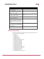
The same basic rule applies to Network Security Platform failover. If the network currently
has parallel firewalls connected to parallel switches, for example, it follows that you can
introduce parallel Sensors between them. The following set of diagrams is a very simple
“before and after,” to help clarify the logic:
Figure 1: Determining optimal sensor location - Before
Note: The dotted line represents a heartbeat link.
7
McAfee® Network Security Platform 6.0
Determining optimal Sensor location
Figure 2: Determining optimal sensor location - After
The key is to ensure the redundant Sensors will be scanning the same traffic at the same
point in the network. If you were to instead place one Sensor outside the firewall on one
path and the other Sensor inside the firewall on the other path, the outcome is what
developers like to refer to as “undefined.” That is, there is no telling what false positives
and false negatives, and even instability, such a setup might produce.
Redundant Sensors on a single path
Sensor failover is typically straightforward to implement in the more complicated
environments because Network Security Platform was engineered to seamless slip onto
networks with existing, redundant paths. The irony is that introducing a Sensor failover
Pair onto a network with a single path often requires some additional thought:
A pair of Sensors can run in parallel on a network that otherwise has no or little
redundancy. For example, you might “sandwich” a pair of Sensors between a pair of
switches and use STP to control the failover process. The drawback to relying on STP,
however, is that you inherently complicate the Layer 2 infrastructure and STP convergence
typically takes between 12 and 50 seconds; so it's not ideal.
8
McAfee® Network Security Platform 6.0
Determining optimal Sensor location
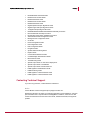
Instead, consider the configuration in Figure “Stack” configuration for a single path:
Figure 3: Stack Configuration
In this scenario, the Sensors are “stacked” (one after the other) in much the same way you
might daisy chain a pair of switches.
Note: A crossover cable is required to make the connection between the Sensor
monitoring ports.
These Sensors are configured to run inline, failopen, and function as a failover Pair.
The advantages of this redundant configuration over others on a network with a single
path are as follows:
•
•
There is no dependency on the Layer 2 or Layer 3 topologies for Sensor redundancy.
If one Sensor fails, it fails open, and the other Sensor continues to scan with no
interruption.
•
Because they are configured as a failover Pair, state will be maintained.
The single disadvantage is that duplicate alerts will be generated for UDP and ICMP
attacks. (More on this later in this document.)
9
McAfee® Network Security Platform 6.0
Determining optimal Sensor location
Preventing duplicate alerts
To prevent the failover Pair from forwarding the same alert twice, each node in the Pair
adheres to the following rules:
•
The Sensor that received the attack packet on its monitoring port sends the signature
alert to McAfee.® Network Security Manager (Manager). (The Sensor that gets a copy
of the attack packet from its failover peer does not send an alert.)
•
The Sensor forwarding the alert also takes the configured response action, such as
sending a TCP reset.
•
The Sensor that has been online the longest is responsible for sending all
reconnaissance and DoS alerts to the Manager.
•
In the event that both Sensors have been up for exactly the same amount time, the
Sensor with the higher value serial number will be responsible for sending all
reconnaissance and DoS alerts.
The reality check is that because the previous “stacked” configuration results in attacks
arriving on the monitoring ports of both Sensors (unless blocking is enabled), this
configuration will cause some duplicate alerts to be generated. The details are as follows:
•
•
•
There will be no issue with reconnaissance and DoS attacks because one Sensor in a
failover Pair is always dedicated to send these alerts.
There will be no issue with TCP signature attacks either, thanks to the stateful nature
of the scanning engine. That is, even though both Sensors will get the attack packet
on their monitoring ports, the second Sensor will actually get the packet on its failover
port first. When it subsequently gets the packet for a second time on its monitoring
port, the packet will be recognized and treated as a duplicate packet. The duplicate
packet will be forwarded along, but no alert will be generated.
However, because UDP and ICMP are not stateful, the same logic does not apply to
those packets. Instead, UDP and ICMP attacks will create duplicate alerts in this
configuration.
Summary
If the current network failover topology has been configured in a logical fashion, you will no
doubt see a pattern as you research the existing infrastructure. In this case, follow that
pattern when you add the Sensors. If the current topology does not follow a logical pattern,
address the issue before you consider adding Network Security Platform failover, and
avoid the possibility of Network Security Platform taking the blame for a flaw in the network
design.
10
CHAPTER 6
Configuring the ports on each Sensor
To function as a failover Pair, the two McAfee® Network Security Sensors (Sensors) must
be the same model and have the same Sensor image (Sensor software version).
Previously, you could create Sensor fail-over pair only if all the monitoring ports of the
primary sensor were in Inline mode. Now, you can create Sensor fail-over pairs even if the
monitoring ports are in different operating modes, that is some ports in Inline, some in
SPAN, and some in Tap mode. For example, you can create an I-4010 fail-over pair with
monitoring ports 1A-1B, 2A-2B, 3A-3B and 4A-4B deployed in Inline mode and port 5A
deployed in SPAN mode.
In some Sensor models, a monitoring port is configured for the primary-secondary
heartbeat. In such cases, the peer monitoring port is disabled. For example, in I-2700,
monitoring port 4A is used for the heartbeat and when you create the failover pair, port 4B
is disabled.
Note that the port deployment modes of both the primary and secondary Sensors must be
the same. For example, if port 5A is deployed in SPAN mode in the primary then 5A of the
secondary must be deployed in SPAN mode as well.
Figure 4: Sensors - Failover Pairs tab
By design, there will always be a certain amount of independence among the Sensors. For
example, the solution must be flexible enough to handle a network on which a primary
path runs at 100 Mbps full duplex, but the secondary path runs at only 10 Mbps half
duplex.
This is the proper time to configure each port pair to fail open or closed. In previous
Network Security Platform versions, you could only configure each Sensor in a failover
Pair to fail closed. Now, you can configure one Sensor to fail closed and the second to fail
open.
Note: There is no special requirement for a minimum Sensor software version to be
able to configure one Sensor to fail closed and the other to fail open.
You can configure both the port speed and operating mode from the Configure Ports page
of the user interface:
11
McAfee® Network Security Platform 6.0
Configuring the ports on each Sensor
If you choose to fail closed on an Ethernet port pair (not GBICs), the user interface will
remind you to cable the ports with the Network Security Platform dongles.
Note: McAfee® Network Security Platform dongles ship with the Sensors.
Potential pitfall
When you configure a failover Pair, you must designate a “Primary” and “Secondary”
Sensor. By design, the configuration of the Primary Sensor is copied to the Secondary
Sensor, overwriting the original configuration on the Secondary.
If you intend to configure both Sensors to fail closed or fail open, you configure the ports
on the Sensor you intend to designate as the primary during the failover Pair creation
process.
If you intend to have one Sensor fail closed and the other fail open, however, you must
revisit the Port Configuration page of one or both Sensors after the failover Pair creation
and make the appropriate changes.
A note on fail open functionality for GE ports
Unlike the Fast Ethernet ports, the GE ports cannot fail open on their own. You must
purchase an optical bypass kit for each port pair you wish to fail open.
If a Sensor is rebooted, hangs, or fails to come up after a power on, the optical bypass kit
takes over and ensures the link remains active. When configured as a failover Pair, this
logic still applies, except in the case in which the Sensor port actually fails. In this case, the
12
McAfee® Network Security Platform 6.0
Configuring the ports on each Sensor
bypass kit does not change to bypass mode. Instead, the port pair fails closed and the
redundant link takes over.
The details of optical bypass kits are currently beyond the scope of this document. See the
documentation that accompanies the fail open kits (for example, the Gigabit Optical Fail-Open
Bypass Kit Guide, which accompanies the Optical Fail-Open kit).
A caution about active-passive failover
The option to fail one Sensor closed and one Sensor open was intended for use with
active-passive configurations. When the order in which the redundant paths will be used is
known, you can safely configure the Sensor on the primary path to fail closed and the
Sensor on the secondary path to fail open. The result is as follows:
•
If the Sensor on the primary path fails, it will force the secondary path to take over,
which will ensure the link remains protected.
•
In the unlikely event that the secondary path has become active and the Sensor on it
fails as well, traffic will no longer be scanned, but will continue to flow.
You might prefer to shut down the Internet connection if the traffic on the secondary path
cannot be scanned for intrusions. In this case, you would configure both Sensors to fail
closed.
On a network on which both paths are active, there is no way to predict the order in which
the paths will fail. Configuring a Sensor to fail open in this context would at best negate the
purpose of the Network Security Platform redundancy. Furthermore, if there were
asymmetric flows on the paths, the remaining Sensor would not see all the packets from
those flows and therefore be susceptible to false positives and false negatives.
13
CHAPTER 7
How dongles work
Dongles, included with all 10/100-port McAfee® Network Security Sensors (Sensors), are
required when a 10/100 Sensor port runs in SPAN or inline fail-closed mode.
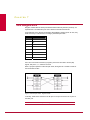
All 10/100 ports on the Sensors are standard 10/100 Base-T Ethernet ports. As such, they
make use of only 4 of the 8 wires in a Category 5/6 twisted pair cable:
Pin
Function
1
Tx
2
Tx
3
Rx
4
5
6
Rx
7
8
Pins 1 and 2 are used to transmit (Tx) signals, pins 3 and 6 are used to receive (Rx)
signals, and pins 4, 5, 7, and 8 are not used.
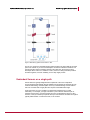
When a port pair operates in inline fail-open mode, the signals are “crossed” to allow for
the normal flow of traffic:
Figure 5: Inline fail-open mode - Signals crossed
In this way, traffic that is received on the Rx pins on one port are sent on the Tx pins on
the other port.
Note: This is the same cross performed by a crossover cable.
14
McAfee® Network Security Platform 6.0
How dongles work
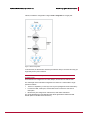
A group of mechanical relays actually resides between each port pair:
Figure 6: Mechanical Relays
The relays come into play when the Sensor is shut down. Specifically, the relays provide a
path for the signals on pins 1, 2, 3, and 6 to continue to pass when the Sensor is powered
off. In short, the relays ensure that the Sensor will fail open.
It is important to note that the relays provide a path for the signals on pins 1, 2, 3, and 6
only. The signals on pins 4, 5, 7, and 8 are instead filtered out.
When the Sensor runs in inline fail-closed mode, the Sensor uses pins 4 and 5 instead of
pins 1 and 2 to transmit signals:
Figure 7: Tx signals on pins 4 and 5
15
McAfee® Network Security Platform 6.0
How dongles work
Again, the relays come into play when the Sensor is powered off:
Figure 8: Mechanical Relay - Fail closed
Because the relays only pass the signals on pins 1, 2, 3, and 6, however, the transmit
signals on pins 4 and 5 are filtered out and the ports fail closed.
So what does the dongle do? The answer becomes obvious when we compare the Sensor
port pin-outs configured for fail-closed operation to standard Ethernet cable pin-outs:
Figure 9: Pin-out comparison
As the previous diagram indicates, a Sensor in fail-closed mode uses pins 4 and 5 to
transmit signals, yet standard 10/100 Ethernet connections use pins 1 and 2 to transmit
signals (pins 4 and 5 are not used). Without a mechanism to transpose the signals, traffic
therefore comes to a halt.
Note: The operating mode of the Sensor has no effect on the receive (Rx) signals,
so they are not shown here for simplicity.
16
McAfee® Network Security Platform 6.0
How dongles work
The sole purpose of the dongles is to transpose the transmit signals from pins 4 and 5
(back) to pins 1 and 2 so the Sensor can communicate with standard Ethernet devices
when powered on:
Figure 10: Dongle transposes signals
The inner workings of the dongle are shown in Figure Inner workings of dongle
Figure 11: Inner workings of dongle
When the transmit signals go from the fail closed port on the Sensor to the male end of the
dongle, they do so on pins 4 and 5. When they go from the female end of the dongles to a
standard 10/100 Base-T cable, however, they use pins 1 and 2, which is the Ethernet
standard.
The same approach is used to prevent loops from a Sensor port operating in SPAN mode.
Imagine that ports 2A and 2B are each running in SPAN mode. When the Sensor is
powered on, because each port is configured for SPAN mode, the Sensor software will
prevent traffic from passing between the pair. But when the Sensor is powered off, the
relays will, by design, allow transmit signals to pass over pins 1 and 2. To avoid this
situation, which will only serve to confuse the remote devices (and even possibly create
bridging loops), Sensor ports configured for SPAN mode also transmit on pins 4 and 5 and
therefore require the dongles.
17
CHAPTER 8
Physically installing the Sensors
Installing McAfee® Network Security Sensors (Sensors) at this point may seem premature.
After all, you will no doubt perform tests once the failover pair has been configured. The
logic here is to confirm connectivity and proper scanning with as few variables as possible.
If basic connectivity and scanning prove to be fine now, but fail after configuring the
failover pair, you at least know the issue is specific to the failover pair.
Ideally, you should test each Sensor individually. This includes, if need be, manually failing
over the Primary path, so traffic will flow across the Secondary path.
You can use common utilities like Ping and Traceroute (tracert.exe on Windows) to test basic
connectivity. You can also look at the statistics from the Threat Analyzer for each Sensor
port to confirm that traffic is properly flowing through it.
Figure 12: Performance Statistics: Data View
Note: For step-by-step procedures on verifying how to verify traffic is flowing
through the Sensor, see the System Status Monitoring Guide.
An easy and benign way to confirm that Network Security Platform is scanning for exploits
is to trigger a FTP directory traversal signature.
18
McAfee® Network Security Platform 6.0
Physically installing the Sensors
The “attack” looks as follows:
Figure 13: FTP traversal “attack”
The highlighted section is the command that actually trips the signature.
The corresponding attack will look similar to the alert in Figure FTP traversal alert.
19
McAfee® Network Security Platform 6.0
Physically installing the Sensors
Figure 14: Show details of Specific attack
If you are interested in HTTP tests, you can instead try the following URLs from your
favorite browser:
http://serveraddress/inetpub/scripts/root.exe
http://serveraddress/inetpub/scripts/cmd.exe
Note: These exploits are specific to IIS.
Caution: These URLs are synonymous with Code Red and Nimda exploits, so they
may trigger anti-virus software on the Web server as well.
Warning: Use these tools for Network Security Platform testing purposes only. McAfee in no
way condones use of attack traffic for any reason other than testing product
connectivity and communication.
20
McAfee® Network Security Platform 6.0
Physically installing the Sensors
Reality check - Asymmetric routing
In the case in which the network has two active paths that route asymmetrically, these
initial intrusion tests might not be successful and you may even see false positives.
In such a case, you can instead temporarily assign the All inclusive with audit policy to the
interface(s) at hand to help confirm the scanning process, or skip testing for now and hope
all goes well in the steps to follow.
21
CHAPTER 9
Defining the Network Security Platform Failover Pair
Once McAfee® Network Security Sensors (Sensors) are known to be working
independently, we are ready to define a failover Pair. It is by way of the failover Pair
configuration that we ensure the Sensors share flow information under normal conditions
and also fail over as required.
In Figure Failover Pair creation, we have specified the Sensor model in question (I-4010),
named the Failover Pair, FO-Pair-4010, and selected the two intended Sensors:
Figure 15: Creating a Failover pair
Again, the one important consideration is that the current configuration of “primary” Sensor
will be copied over that of the “secondary” Sensor during the Pair creation process.
Note: The creation of a failover pair happens in real time. There is no need to
explicitly update the configuration.
When it comes to scanning roles, however, you can safely ignore the terms Primary
Sensor and Secondary Sensor here. Remember that both Sensors are always scanning
actively.
22
McAfee® Network Security Platform 6.0
Defining the Network Security Platform Failover Pair
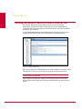
Once complete, the display of the user interface will change to reflect the existence of the
new failover pair:
Figure 16: Update configuration
A new failover pair node now exists in the resource tree (left pane) in Figure Failover Pair
administration. That node contains icons for each interface taking part in the failover
process. Also within the failover pair node is a list of its member Sensors.
Most configuration options are hereafter done at the failover pair node level. For example,
you can now apply a policy, update the configuration, or even create an ACL rule at the
failover pair node level and it will automatically propagate to each of the member Sensors.
On the other hand, you still configure the port settings, view interface statistics, and
upgrade the Sensor software at the Sensor node level. So the easiest way to get a feel for
the failover pair configuration process is to examine the user interface once the pair has
been created.
Note: The Sensors must be running the same software version to run in a failover
configuration. However, you upgrade software at a Sensor level, even those that are
part of a failover pair. The recommended upgrade procedure is to therefore upgrade
the software version on both Sensors, and then reboot them sequentially. That is,
once the upgrade process is complete on both, reboot the first, confirm that it has
rebooted without error, and reboot the second.
23
McAfee® Network Security Platform 6.0
Defining the Network Security Platform Failover Pair
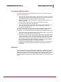
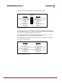
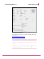
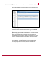
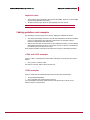
It is very easy to see the details of the port status across all Sensors from the View Details
page at the Sensors level:
Figure 17: Sensor status and operational details
For additional details, you can dive down on the current failover status for a given interface
from the View Details page of that interface:
Figure 18: CIDR Interface Details Example
In the previous figure you will notice that the logical operational status of the interface is
UP, but the operational status for the secondary Sensor is DOWN. This means the failover
pair is working as planned, but there is an issue with the physical Sensor. (As it turns out,
the wires have been pulled from the 3A/3B port pair on the secondary Sensor here.)
24
CHAPTER 10
Cabling the heartbeat connection
There is no standard heartbeat port across all McAfee® Network Security Sensor (Sensor)
models. Instead, the port or ports you use to connect the two Sensors for failover depends
directly on the model at hand. The details are as follows:
Sensor model
Port(s) used for heartbeat connection
I-4010
6A and 6B (HA1 and HA2)
I-4000
2A and 2B
I-3000
6A and 6B (HA1 and HA2)
I-2700
4A
I-1400
R1 (response port)
I-1200
R1 (response port)
Sensor model
Port(s) used for heartbeat connection
M-8000
3A and 3B (HA1 and HA2)
M-6050
4A (HA1—note that port 4B remains unused)
M-4050
2A
M-3050
2A
M-2750
10A
M-1450
4A
M-1250
4A
N-450
10A and 10B
Initial hints
Consider these hints when cabling:
•
•
•
•
The I-3000, I-4000, I-4010, models require two ports to share flow information at a
high throughput level.
Only port 4A is actually used for the heartbeat connection on the I-2700 model. Port
4B is disabled when in failover mode.
Ports 6A and 6B are labeled HA1 and HA2, respectively, on the I-3000 and I-4010
models to indicate their use in the failover process. (HA stands for High Availability.)
To cable the heartbeat connection on the I-1200 and I-1400 Sensors, connect the
Response ports of the primary and secondary using a crossover cable.
25
McAfee® Network Security Platform 6.0
Cabling the heartbeat connection
GBIC cabling
All Sensor models other than the I-1200 and I-1400 use a standard GBIC, Small Formfactor Pluggable (SFP) GBIC, or 10GbE Small Form-factor Pluggable (XFP) GBIC to make
the heartbeat connection.
Before you attempt to cable failover with a GBIC, complete the following steps:
1
Determine the appropriate GBIC (standard, SFP, or XFP) for the model at hand.
2
Determine the connector type required to plug the fiber optic cable into the chosen
GBIC.
3
Determine the correct GBIC module type and cable to support the distance between
the Sensor pair.
Note: If you are using copper GBICs, then use Category 6 Enhanced (Cat 6e)
straight cable.
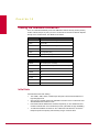
The table below addresses the first two steps. It builds off the previous table to include
columns for the port type and corresponding cable connector type:
I-series Sensor data:
Sensor model Port(s) used for heartbeat connection Port type Cable connector type
I-4010
6A and 6B (HA1 and HA2)
SFP
LC
I-4000
2A and 2B
GBIC
SC
I-3000
6A and 6B (HA1 and HA2)
SFP
LC
I-2700
4A
GBIC
SC
I-1400
R1 (response port)
Ethernet RJ45
I-1200
R1 (response port)
Ethernet RJ45
M-series Sensor and N-450 Sensor data:
Sensor
model
Port(s) used for heartbeat connection
Port
type
Cable connector
type
M-8000
3A and 3B (HA1 and HA2)
XFP
LC
M-6050
4A (HA1—Note that port 4B or HA2
remains unused)
XFP
LC
M-4050
2A
XFP
LC
M-3050
2A
XFP
LC
M-2750
10A
SFP
LC
M-1450
4A
Copper
RJ45
M-1250
4A
Copper
RJ45
N-450
10A and 10B
SFP
LC
26
McAfee® Network Security Platform 6.0
Cabling the heartbeat connection
Important notes
•
•
The monitoring ports and failover ports use the same GBIC. (There is no special GBIC
required for the heartbeat connection.)
All GBICs and fiber optic cables are sold separately from the Sensors.
Note : McAfee only officially supports GBICs purchased from McAfee price list.
Cabling guidelines and examples
The following is a quick summary of the rules for cabling the heartbeat connection:
•
The cabling must always cross the Tx and Rx channels between the Sensor heartbeat
ports. It is for this reason the I-1200 and I-1400 Sensors, for example, require a
crossover cable between their failover pairs.
•
When 2 ports are used on each Sensor for the heartbeat connection, you must always
cable between identical port names. For example, port 2A on Sensor 1 should always
be cabled to port 2A on Sensor 2 (not 2B).
Some sample hardware requirements and setup hints are given in the following sections:
I-1200 and I-1400 examples
A pair of I-1200 or I-1400 Sensors located within 100 meters or less of each other would
require:
•
One (1) CAT 5 crossover cable
Connect the crossover cable to each response port.
I-2700 examples
A pair of I-2700 Sensors located within 550 meters of each other would require:
•
Two (2) standard SX GBICs
•
One (1) SX fiber optic cable with SC connectors
You need 2 GBICs and a single cable because I-2700 Sensors only use port 4A for
Sensor-to-Sensor communication.
27
McAfee® Network Security Platform 6.0
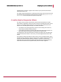
Cabling the heartbeat connection
The key to a successful fiber optic connection is to make sure the cable is crossed
between the Sensors:
Figure 19: Running Cables
In the previous photo, for example, the white connector is on the left side of the GBIC in
the top Sensor and on the right side of the GBIC in the bottom Sensor.
I-4000 example
A pair of I-4000 Sensors located within 10 Km of each other would require:
•
Four (4) standard LX/LH GBICs
•
Two (2) LX/LH fiber optic cables with SC connectors
The cabling logic here is similar to the logic used with the I-2700 model. The key difference
is that the I-4000 uses ports 2A and 2B for the heartbeat connection. It follows that you
take the same approach as above, but do it twice. Specifically, you cross the cable from
port 2A on the first Sensor to port 2A on the second Sensor, and then repeat the step
between port 2B on the first Sensor and 2B on the second Sensor.
I-3000 and I-4010 examples
A pair of I-3000 or I-4010 Sensors located within 100 Km of each other would require:
•
Four (4) SFP ZX GBICs
•
Two (2) ZX fiber optic cables with LC connectors
The approach to cabling here is the same as it is for the I-4000, except the I-3000 and I4010 use ports 6A and 6B (HA1 and HA2) for the heartbeat connection.
Warning: Network Security Platform has been known to work fine with ZX GBICs.
However, McAfee does not sell or actively test with ZX GBICs.
TX GBICs
McAfee also offers a TX module type for both the standard and SFP GBICs. The TX
module type is used to connect to twisted pair (copper). With the TX module, the required
28
McAfee® Network Security Platform 6.0
Cabling the heartbeat connection
cable connector type is indeed RJ45 and the maximum distance is that of standard twisted
pair (100 meters).
If desired, TX modules can be used to provide the failover connection. This is not
traditionally done, however, because the SX modules are less expensive and have a
greater maximum distance.
Note: The TX module can only be used at 1000 Mbps: there is currently no option to
run the TX module at 10/100 Mbps.
Cabling failover through a network device
Do not cable the heartbeat connection through an external network device!
To keep overhead low and throughput high, the Sensors do not include layer 2 or 3
headers on the packets they pass over the heartbeat connection, and they pass data
larger than the standard Ethernet maximum frame size (1518 bytes).
If you attempt to place a network device, such as a switch or router, between the heartbeat
ports, the heartbeat connection will fail.
29
CHAPTER 11
Verifying the failover configuration
The final steps are to:
•
Confirm McAfee® Network Security Sensors (Sensors) are communicating over the
heartbeat connection
Test the failover setup
•
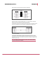
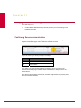
Confirming Sensor communication
Once the failover pair has been configured, failover peer status errors will appear on the
System Health Status page until you cable the heartbeat connection:
Figure 20: Faults of Type: Warning Message for the Manager
Item
Description
1
Click link for specific fault detail.
2
Action buttons.
The status of the communication between the Sensors can be monitored on the
Sensors/View Details page of the Web-based user interface or directly from the CLI of
either Sensor.
The Sensors represented by the previous screenshot might therefore be properly cabled,
but just need to be rebooted.
30
McAfee® Network Security Platform 6.0
Verifying the failover configuration
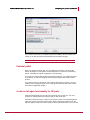
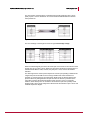
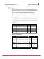
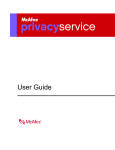
From within the CLI, you can instead run the command from either Sensor. The output
includes the failover Enabled and Peer Status fields. The former indicates whether the
Sensor at hand has been configured to be part of a failover pair, and the latter shows the
current state of the communication between the two Sensors:
Figure 21: show failover-status
In Figure show failover-status, the Sensor is part of a failover pair, and the pair is successfully
communicating over the heartbeat connection.
Testing failover setup
Once communication between the Sensors has been confirmed, the failover configuration
should be tested.
The way in which the configuration is best validated will vary from setup to setup, but these
tests should be similar to the ones performed after the Sensors were physically installed
on the network.
The key differences this time include the following:
•
In the specific case in which the network at hand has two active paths that route
asymmetrically, the intrusion tests that previously failed should now be successful
because both Sensors are analyzing all packets from all flows.
•
Existing session state should not be lost when a Sensor goes offline.
The most precise way to confirm that the session remained intact after the “failure” is to
capture and analyze packets. A more rudimentary test is to open a browser and start a
large download while one Sensor is taken offline. If the state is successfully kept, there will
be no fatal interruption in the download process.
If the state is lost, confirm that the Sensors are indeed communicating with each other.
If the Sensors are not communicating, try the following steps in the order shown:
31
McAfee® Network Security Platform 6.0
Verifying the failover configuration
1
Cold start both Sensors.
2
Reconnect the cabling between them.
3
Recreate the failover pair.
4
If GBICs are used, confirm that McAfee supplied them.
Caution: Non-McAfee GBICs are known to create problems. If the GBICs used are
not from McAfee pricelist, temporarily swap them out for those that are before
spending more time troubleshooting.
If they are communicating:
1
Capture packets simultaneously on both redundant paths. This will provide a full
picture of the data flow, and no doubt insight into the problem.
32
CHAPTER 12
Network Scenarios for Sensor High Availability
In the below use-case scenarios, the term Active/Passive refers to network topology and
not the Sensor High Availability (HA) configuration. In Sensor HA, both the Sensors are in
Active/Active state meaning both the Sensors will process traffic received on their
respective monitoring ports.
I-4010 Sensor in Load balanced Configuration
Scenario:
Two I-4010 Sensors are in load-balanced configuration. Each Sensor is monitoring an
active 1GB full duplex link - 500 Mbps in both directions- so each Sensor is handling
1Gbps of traffic. That is the total 2 Gbps throughput for each Sensor is utilized.
Will the total throughput that the Sensors need to handle is more, i.e. will the pair scan 4
Gbps of traffic when combined?
Solution:
When used in the High Availability mode, the total aggregate throughput of Sensor pair
remains the same as in the standalone mode. i.e., Total throughput capability of the pair
<= the quoted throughput rate of the single Sensor. This remains the same when the total
traffic is not evenly distributed across the Sensors.
For example, an I-4010 will scan for 2Gbps in standalone mode, as well as HA mode.
If X is the throughput of one Sensor and Y is the throughput of the second Sensor,
X +Y <= the quoted throughput rate of the Sensor model. Suppose X = 2Gbps and Y =
2Gbps, so the total is 4 Gbps, which exceeds the limit of the total throughput capability of
2Gbps that the pair can handle.
Both Sensors share all data they receive on their monitoring ports with their peers and,
most importantly, both Sensors process the data they receive from their peers. So when
you count how much data an individual Sensor in HA mode is seeing per second, you
have to include both the data it is receiving on its monitoring ports as well as the data it is
receiving from its peer via the HA / interconnect ports.
I-4010 Sensor in Active/Active HA mode
Scenario:
Suppose there are two I-4010's in active/active HA mode with 500Mbps of traffic in both
directions (full duplex), then how does the pair work?
33
McAfee® Network Security Platform 6.0
Network Scenarios for Sensor High Availability
Solution:
Each 4010 can scan up to 2 Gbps at any time -standalone or part of an HA pair.
In the above case, the aggregate throughput for the pair would be 2Gbps - processed on
each Sensor.
As long as the traffic on the monitoring ports of the Sensor on both the active links stays at
or below an aggregate rate of 2 Gbps, the deployment works fine.
I-4010 Sensor in Active/Passive HA mode
Scenario:
Suppose there are two I-4010's in active/passive HA mode with 1 Gbps throughput in full
duplex (500Mbps of traffic in both directions), then how does the pair work?
Solution:
In the above case, the aggregate throughput for the pair would be 2Gbps - 2 Gbps on the
active Sensor and 0 Gbps on the passive Sensor.
In this scenario, the Sensor on the active link receives 1 Gbps of traffic on its monitoring
ports and nothing on its HA ports, because the other Sensor is on the passive link. The
Sensor on the Active link sends a copy of the 1 Gbps of traffic to its peer and processes
the same traffic without issue- because 1 Gbps is only 50% of the single Sensor
throughput.
The 500 Mbps of traffic in each direction, i.e., total 1 Gbps of traffic is well under what the
I-4010 Sensor can handle. Even if the 1 Gbps link is fully saturated, the total would be 2
Gbps in full duplex and this can be handled by the Sensor.
34
Hot Standby Router Protocol ................................... 1
I
Index
inline fail-open mode.............................................. 12
A
active/active ............................................................. 4
M
mechanical relays .................................................. 12
active/passive........................................................... 4
Assymetric Routing ................................................ 16
N
C
network scenarios .................................................. 26
network topology...................................................... 4
cabling guidelines................................................... 21
cabling heart beat connection ................................ 19
Category 5/6 twisted pair cable.............................. 12
configuring ports....................................................... 9
O
operating mode configuration .................................. 9
optimal sensor location ............................................ 6
conventions ............................................................. iv
crossover cable ............................................ 7, 12, 21
P
D
performance statistics ............................................ 15
dongles............................................................... 9, 12
port speed configuration .......................................... 9
primary sensor ................................................. 10, 17
duplicate alerts ......................................................... 7
F
fail-closed ........................................................... 9, 10
failing closed .......................................................... 10
R
redundant path......................................................... 6
redundant sensors ............................................... 6, 7
Rx pins ................................................................... 12
failing open............................................................... 9
fail-open for GE ports ............................................. 10
failover architecture.............................................. 2, 3
failover implementation ............................................ 3
failover pair creation............................................... 17
failover pair node.................................................... 17
failover share flow information ................................. 2
G
GBIC cabling .......................................................... 20
H
heartbeat link.......................................... 6, 19, 20, 23
high availability..................................................... 1, 2
S
single path topology ................................................. 5
SPAN/hub operating mode
deploying the I-1200 in...................................... 12
stack configuration ................................................... 7
STP convergence .................................................... 7
T
technical support.....................................................vii
testing failover setup .............................................. 25
Tx pins ................................................................... 12
V
verifying failover configuration.......................... 24, 25
Virtual IP................................................................... 1
Virtual Router Redundancy Protocol........................ 1