1
Alcatel-Lucent 7705
SERVICE AGGREGATION ROUTER OS | RELEASE 4.0
BASIC SYSTEM CONFIGURATION GUIDE
Alcatel-Lucent Proprietary
This document contains proprietary information of Alcatel-Lucent and is not to be disclosed
or used except in accordance with applicable agreements.
Copyright 2010 © Alcatel-Lucent. All rights reserved.
Alcatel-Lucent assumes no responsibility for the accuracy of the information presented, which is
subject to change without notice.
Alcatel, Lucent, Alcatel-Lucent and the Alcatel-Lucent logo are trademarks of Alcatel-Lucent. All
other trademarks are the property of their respective owners.
Copyright 2010 Alcatel-Lucent.
All rights reserved.
Disclaimers
Alcatel-Lucent products are intended for commercial uses. Without the appropriate network design
engineering, they must not be sold, licensed or otherwise distributed for use in any hazardous
environments requiring fail-safe performance, such as in the operation of nuclear facilities, aircraft
navigation or communication systems, air traffic control, direct life-support machines, or weapons
systems, in which the failure of products could lead directly to death, personal injury, or severe physical
or environmental damage. The customer hereby agrees that the use, sale, license or other distribution
of the products for any such application without the prior written consent of Alcatel-Lucent, shall be at
the customer's sole risk. The customer hereby agrees to defend and hold Alcatel-Lucent harmless from
any claims for loss, cost, damage, expense or liability that may arise out of or in connection with the
use, sale, license or other distribution of the products in such applications.
This document may contain information regarding the use and installation of non-Alcatel-Lucent
products. Please note that this information is provided as a courtesy to assist you. While Alcatel-Lucent
tries to ensure that this information accurately reflects information provided by the supplier, please refer
to the materials provided with any non-Alcatel-Lucent product and contact the supplier for
confirmation. Alcatel-Lucent assumes no responsibility or liability for incorrect or incomplete
information provided about non-Alcatel-Lucent products.
However, this does not constitute a representation or warranty. The warranties provided for
Alcatel-Lucent products, if any, are set forth in contractual documentation entered into by
Alcatel-Lucent and its customers.
This document was originally written in English. If there is any conflict or inconsistency between the
English version and any other version of a document, the English version shall prevail.
When printed by Alcatel-Lucent, this document is printed on recycled paper.
Table of Contents
Preface . . . . . . . . . . . . . . . . . . . . . . . . . . . . . . . . . . . . . . . . . . . . . . . . . . . . . . . . . . . . . . . . . . . . . . . . . 27
Getting Started . . . . . . . . . . . . . . . . . . . . . . . . . . . . . . . . . . . . . . . . . . . . . . . . . . . . . . . . . . . . . . . . . . . 31
Alcatel-Lucent 7705 SAR System Configuration Process. . . . . . . . . . . . . . . . . . . . . . . . . . . . . . . . . . . . . . . . . 31
Notes on 7705 SAR-8, 7705 SAR-18, and 7705 SAR-F . . . . . . . . . . . . . . . . . . . . . . . . . . . . . . . . . . . . . . . 33
CLI Usage . . . . . . . . . . . . . . . . . . . . . . . . . . . . . . . . . . . . . . . . . . . . . . . . . . . . . . . . . . . . . . . . . . . . . . . 35
CLI Structure . . . . . . . . . . . . . . . . . . . . . . . . . . . . . . . . . . . . . . . . . . . . . . . . . . . . . . . . . . . . . . . . . . . . . . . . . . .
Navigating in the CLI. . . . . . . . . . . . . . . . . . . . . . . . . . . . . . . . . . . . . . . . . . . . . . . . . . . . . . . . . . . . . . . . . . . . .
CLI Contexts . . . . . . . . . . . . . . . . . . . . . . . . . . . . . . . . . . . . . . . . . . . . . . . . . . . . . . . . . . . . . . . . . . . . . . . .
Basic CLI Commands . . . . . . . . . . . . . . . . . . . . . . . . . . . . . . . . . . . . . . . . . . . . . . . . . . . . . . . . . . . . . . . . .
CLI Environment Commands . . . . . . . . . . . . . . . . . . . . . . . . . . . . . . . . . . . . . . . . . . . . . . . . . . . . . . . . . . .
CLI Monitor Commands . . . . . . . . . . . . . . . . . . . . . . . . . . . . . . . . . . . . . . . . . . . . . . . . . . . . . . . . . . . . . . .
Getting Help in the CLI . . . . . . . . . . . . . . . . . . . . . . . . . . . . . . . . . . . . . . . . . . . . . . . . . . . . . . . . . . . . . . . . . . .
The CLI Command Prompt . . . . . . . . . . . . . . . . . . . . . . . . . . . . . . . . . . . . . . . . . . . . . . . . . . . . . . . . . . . . . . . .
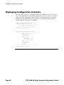
Displaying Configuration Contexts . . . . . . . . . . . . . . . . . . . . . . . . . . . . . . . . . . . . . . . . . . . . . . . . . . . . . . . . . .
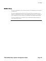
EXEC Files . . . . . . . . . . . . . . . . . . . . . . . . . . . . . . . . . . . . . . . . . . . . . . . . . . . . . . . . . . . . . . . . . . . . . . . . . . . .
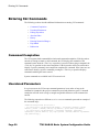
Entering CLI Commands. . . . . . . . . . . . . . . . . . . . . . . . . . . . . . . . . . . . . . . . . . . . . . . . . . . . . . . . . . . . . . . . . .
Command Completion . . . . . . . . . . . . . . . . . . . . . . . . . . . . . . . . . . . . . . . . . . . . . . . . . . . . . . . . . . . . . . . .
Unordered Parameters . . . . . . . . . . . . . . . . . . . . . . . . . . . . . . . . . . . . . . . . . . . . . . . . . . . . . . . . . . . . . . . .
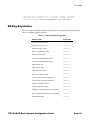
Editing Keystrokes . . . . . . . . . . . . . . . . . . . . . . . . . . . . . . . . . . . . . . . . . . . . . . . . . . . . . . . . . . . . . . . . . . .
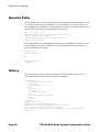
Absolute Paths . . . . . . . . . . . . . . . . . . . . . . . . . . . . . . . . . . . . . . . . . . . . . . . . . . . . . . . . . . . . . . . . . . . . . .
History . . . . . . . . . . . . . . . . . . . . . . . . . . . . . . . . . . . . . . . . . . . . . . . . . . . . . . . . . . . . . . . . . . . . . . . . . . . . .
Entering Numerical Ranges . . . . . . . . . . . . . . . . . . . . . . . . . . . . . . . . . . . . . . . . . . . . . . . . . . . . . . . . . . . .
Pipe/Match . . . . . . . . . . . . . . . . . . . . . . . . . . . . . . . . . . . . . . . . . . . . . . . . . . . . . . . . . . . . . . . . . . . . . . . . .
Redirection . . . . . . . . . . . . . . . . . . . . . . . . . . . . . . . . . . . . . . . . . . . . . . . . . . . . . . . . . . . . . . . . . . . . . . . . .
Basic Command Reference . . . . . . . . . . . . . . . . . . . . . . . . . . . . . . . . . . . . . . . . . . . . . . . . . . . . . . . . . . . . . . .
Command Hierarchies . . . . . . . . . . . . . . . . . . . . . . . . . . . . . . . . . . . . . . . . . . . . . . . . . . . . . . . . . . . . . . . .
Command Descriptions . . . . . . . . . . . . . . . . . . . . . . . . . . . . . . . . . . . . . . . . . . . . . . . . . . . . . . . . . . . . . . . .
Basic CLI Commands . . . . . . . . . . . . . . . . . . . . . . . . . . . . . . . . . . . . . . . . . . . . . . . . . . . . . . . . . . . . . .
Environment Commands . . . . . . . . . . . . . . . . . . . . . . . . . . . . . . . . . . . . . . . . . . . . . . . . . . . . . . . . . . . .
Monitor CLI Commands . . . . . . . . . . . . . . . . . . . . . . . . . . . . . . . . . . . . . . . . . . . . . . . . . . . . . . . . . . . . .
Show Commands . . . . . . . . . . . . . . . . . . . . . . . . . . . . . . . . . . . . . . . . . . . . . . . . . . . . . . . . . . . . . . . . .
36
39
39
40
43
43
45
47
48
49
50
50
50
51
52
52
53
54
56
59
59
61
62
76
80
96
File System Management . . . . . . . . . . . . . . . . . . . . . . . . . . . . . . . . . . . . . . . . . . . . . . . . . . . . . . . . . . 97
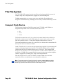
The File System . . . . . . . . . . . . . . . . . . . . . . . . . . . . . . . . . . . . . . . . . . . . . . . . . . . . . . . . . . . . . . . . . . . . . . . . 98
Compact Flash Device . . . . . . . . . . . . . . . . . . . . . . . . . . . . . . . . . . . . . . . . . . . . . . . . . . . . . . . . . . . . . . . . 98
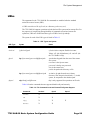
URLs . . . . . . . . . . . . . . . . . . . . . . . . . . . . . . . . . . . . . . . . . . . . . . . . . . . . . . . . . . . . . . . . . . . . . . . . . . . . . . 99
Wildcards . . . . . . . . . . . . . . . . . . . . . . . . . . . . . . . . . . . . . . . . . . . . . . . . . . . . . . . . . . . . . . . . . . . . . . . . . 101
Common Configuration Tasks. . . . . . . . . . . . . . . . . . . . . . . . . . . . . . . . . . . . . . . . . . . . . . . . . . . . . . . . . . . . . 102
Modifying File Attributes . . . . . . . . . . . . . . . . . . . . . . . . . . . . . . . . . . . . . . . . . . . . . . . . . . . . . . . . . . . . . . 102
Creating and Navigating Directories . . . . . . . . . . . . . . . . . . . . . . . . . . . . . . . . . . . . . . . . . . . . . . . . . . . . . 103
Copying Files . . . . . . . . . . . . . . . . . . . . . . . . . . . . . . . . . . . . . . . . . . . . . . . . . . . . . . . . . . . . . . . . . . . . . . 103
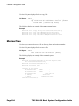
Moving Files . . . . . . . . . . . . . . . . . . . . . . . . . . . . . . . . . . . . . . . . . . . . . . . . . . . . . . . . . . . . . . . . . . . . . . . 104
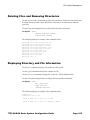
Deleting Files and Removing Directories . . . . . . . . . . . . . . . . . . . . . . . . . . . . . . . . . . . . . . . . . . . . . . . . . 105
Displaying Directory and File Information . . . . . . . . . . . . . . . . . . . . . . . . . . . . . . . . . . . . . . . . . . . . . . . . . 105
7705 SAR OS Basic System Configuration Guide
Page 3
Table of Contents
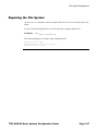
Repairing the File System . . . . . . . . . . . . . . . . . . . . . . . . . . . . . . . . . . . . . . . . . . . . . . . . . . . . . . . . . . . . .
File System Command Reference . . . . . . . . . . . . . . . . . . . . . . . . . . . . . . . . . . . . . . . . . . . . . . . . . . . . . . . . .
Command Hierarchy . . . . . . . . . . . . . . . . . . . . . . . . . . . . . . . . . . . . . . . . . . . . . . . . . . . . . . . . . . . . . . . . .
Command Descriptions . . . . . . . . . . . . . . . . . . . . . . . . . . . . . . . . . . . . . . . . . . . . . . . . . . . . . . . . . . . . . . .
Configuration Commands . . . . . . . . . . . . . . . . . . . . . . . . . . . . . . . . . . . . . . . . . . . . . . . . . . . . . . . . . .
107
109
109
110
111
Boot Options . . . . . . . . . . . . . . . . . . . . . . . . . . . . . . . . . . . . . . . . . . . . . . . . . . . . . . . . . . . . . . . . . . . 121
System Initialization . . . . . . . . . . . . . . . . . . . . . . . . . . . . . . . . . . . . . . . . . . . . . . . . . . . . . . . . . . . . . . . . . . . .
Configuration and Image Loading . . . . . . . . . . . . . . . . . . . . . . . . . . . . . . . . . . . . . . . . . . . . . . . . . . . . . . .
Persistence . . . . . . . . . . . . . . . . . . . . . . . . . . . . . . . . . . . . . . . . . . . . . . . . . . . . . . . . . . . . . . . . . . . . . .
Automatic Discovery Protocol . . . . . . . . . . . . . . . . . . . . . . . . . . . . . . . . . . . . . . . . . . . . . . . . . . . . . . . . . .
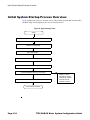
Initial System Startup Process Overview . . . . . . . . . . . . . . . . . . . . . . . . . . . . . . . . . . . . . . . . . . . . . . . . . . . .
Configuration Notes . . . . . . . . . . . . . . . . . . . . . . . . . . . . . . . . . . . . . . . . . . . . . . . . . . . . . . . . . . . . . . . . . . . .
Reference Sources . . . . . . . . . . . . . . . . . . . . . . . . . . . . . . . . . . . . . . . . . . . . . . . . . . . . . . . . . . . . . . . . . .
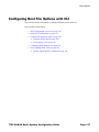
Configuring Boot File Options with CLI . . . . . . . . . . . . . . . . . . . . . . . . . . . . . . . . . . . . . . . . . . . . . . . . . . . . . .
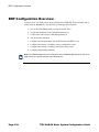
BOF Configuration Overview . . . . . . . . . . . . . . . . . . . . . . . . . . . . . . . . . . . . . . . . . . . . . . . . . . . . . . . . . . . . .
Basic BOF Configuration. . . . . . . . . . . . . . . . . . . . . . . . . . . . . . . . . . . . . . . . . . . . . . . . . . . . . . . . . . . . . . . . .
Common Configuration Tasks. . . . . . . . . . . . . . . . . . . . . . . . . . . . . . . . . . . . . . . . . . . . . . . . . . . . . . . . . . . . .
Searching for the BOF . . . . . . . . . . . . . . . . . . . . . . . . . . . . . . . . . . . . . . . . . . . . . . . . . . . . . . . . . . . . . . .
Accessing the CLI . . . . . . . . . . . . . . . . . . . . . . . . . . . . . . . . . . . . . . . . . . . . . . . . . . . . . . . . . . . . . . . . . . .
Console Connection . . . . . . . . . . . . . . . . . . . . . . . . . . . . . . . . . . . . . . . . . . . . . . . . . . . . . . . . . . . . . . .
Configuring BOF Parameters . . . . . . . . . . . . . . . . . . . . . . . . . . . . . . . . . . . . . . . . . . . . . . . . . . . . . . . . . . . . .
Service Management Tasks . . . . . . . . . . . . . . . . . . . . . . . . . . . . . . . . . . . . . . . . . . . . . . . . . . . . . . . . . . . . . .
System Administration Commands . . . . . . . . . . . . . . . . . . . . . . . . . . . . . . . . . . . . . . . . . . . . . . . . . . . . . .
Viewing the Current Configuration . . . . . . . . . . . . . . . . . . . . . . . . . . . . . . . . . . . . . . . . . . . . . . . . . . . .
Modifying and Saving a Configuration . . . . . . . . . . . . . . . . . . . . . . . . . . . . . . . . . . . . . . . . . . . . . . . . .
Deleting BOF Parameters. . . . . . . . . . . . . . . . . . . . . . . . . . . . . . . . . . . . . . . . . . . . . . . . . . . . . . . . . . .
Saving a Configuration to a Different Filename . . . . . . . . . . . . . . . . . . . . . . . . . . . . . . . . . . . . . . . . . .
Rebooting . . . . . . . . . . . . . . . . . . . . . . . . . . . . . . . . . . . . . . . . . . . . . . . . . . . . . . . . . . . . . . . . . . . . . . .
BOF Command Reference . . . . . . . . . . . . . . . . . . . . . . . . . . . . . . . . . . . . . . . . . . . . . . . . . . . . . . . . . . . . . . .
Command Hierarchies . . . . . . . . . . . . . . . . . . . . . . . . . . . . . . . . . . . . . . . . . . . . . . . . . . . . . . . . . . . . . . .
Command Descriptions . . . . . . . . . . . . . . . . . . . . . . . . . . . . . . . . . . . . . . . . . . . . . . . . . . . . . . . . . . . . . . .
Configuration Commands . . . . . . . . . . . . . . . . . . . . . . . . . . . . . . . . . . . . . . . . . . . . . . . . . . . . . . . . . .
Show Commands . . . . . . . . . . . . . . . . . . . . . . . . . . . . . . . . . . . . . . . . . . . . . . . . . . . . . . . . . . . . . . . .
122
126
129
129
134
135
135
137
138
139
140
140
142
142
144
146
146
146
148
148
149
150
151
151
153
154
170
System Management . . . . . . . . . . . . . . . . . . . . . . . . . . . . . . . . . . . . . . . . . . . . . . . . . . . . . . . . . . . . . 175
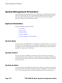
System Management Parameters. . . . . . . . . . . . . . . . . . . . . . . . . . . . . . . . . . . . . . . . . . . . . . . . . . . . . . . . . .
System Information . . . . . . . . . . . . . . . . . . . . . . . . . . . . . . . . . . . . . . . . . . . . . . . . . . . . . . . . . . . . . . . . . .
System Name . . . . . . . . . . . . . . . . . . . . . . . . . . . . . . . . . . . . . . . . . . . . . . . . . . . . . . . . . . . . . . . . . . . .
System Contact . . . . . . . . . . . . . . . . . . . . . . . . . . . . . . . . . . . . . . . . . . . . . . . . . . . . . . . . . . . . . . . . . .
System Location . . . . . . . . . . . . . . . . . . . . . . . . . . . . . . . . . . . . . . . . . . . . . . . . . . . . . . . . . . . . . . . . . .
System Coordinates . . . . . . . . . . . . . . . . . . . . . . . . . . . . . . . . . . . . . . . . . . . . . . . . . . . . . . . . . . . . . . .
Common Language Location Identifier. . . . . . . . . . . . . . . . . . . . . . . . . . . . . . . . . . . . . . . . . . . . . . . . .
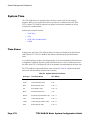
System Time . . . . . . . . . . . . . . . . . . . . . . . . . . . . . . . . . . . . . . . . . . . . . . . . . . . . . . . . . . . . . . . . . . . . . .
Time Zones. . . . . . . . . . . . . . . . . . . . . . . . . . . . . . . . . . . . . . . . . . . . . . . . . . . . . . . . . . . . . . . . . . . . . .
NTP. . . . . . . . . . . . . . . . . . . . . . . . . . . . . . . . . . . . . . . . . . . . . . . . . . . . . . . . . . . . . . . . . . . . . . . . . . . .
SNTP Time Synchronization. . . . . . . . . . . . . . . . . . . . . . . . . . . . . . . . . . . . . . . . . . . . . . . . . . . . . . . . .
CRON . . . . . . . . . . . . . . . . . . . . . . . . . . . . . . . . . . . . . . . . . . . . . . . . . . . . . . . . . . . . . . . . . . . . . . . . . .
Page 4
176
176
176
176
176
177
177
178
178
180
181
181
7705 SAR OS Basic System Configuration Guide
Table of Contents
High Availability. . . . . . . . . . . . . . . . . . . . . . . . . . . . . . . . . . . . . . . . . . . . . . . . . . . . . . . . . . . . . . . . . . . . . . . .
High Availability Features . . . . . . . . . . . . . . . . . . . . . . . . . . . . . . . . . . . . . . . . . . . . . . . . . . . . . . . . . . . . .
Redundancy . . . . . . . . . . . . . . . . . . . . . . . . . . . . . . . . . . . . . . . . . . . . . . . . . . . . . . . . . . . . . . . . . . . . .
Nonstop Routing (NSR) . . . . . . . . . . . . . . . . . . . . . . . . . . . . . . . . . . . . . . . . . . . . . . . . . . . . . . . . . . . .
In-service Upgrade . . . . . . . . . . . . . . . . . . . . . . . . . . . . . . . . . . . . . . . . . . . . . . . . . . . . . . . . . . . . . . . .
CSM Switchover . . . . . . . . . . . . . . . . . . . . . . . . . . . . . . . . . . . . . . . . . . . . . . . . . . . . . . . . . . . . . . . . . .
Synchronization . . . . . . . . . . . . . . . . . . . . . . . . . . . . . . . . . . . . . . . . . . . . . . . . . . . . . . . . . . . . . . . . . .
Synchronization and Redundancy . . . . . . . . . . . . . . . . . . . . . . . . . . . . . . . . . . . . . . . . . . . . . . . . . . . . . . . . .
Active and Standby Designations . . . . . . . . . . . . . . . . . . . . . . . . . . . . . . . . . . . . . . . . . . . . . . . . . . . . . . .
When the Active CSM Goes Offline . . . . . . . . . . . . . . . . . . . . . . . . . . . . . . . . . . . . . . . . . . . . . . . . . . . . .
Administrative Tasks . . . . . . . . . . . . . . . . . . . . . . . . . . . . . . . . . . . . . . . . . . . . . . . . . . . . . . . . . . . . . . . . .
Saving Configurations. . . . . . . . . . . . . . . . . . . . . . . . . . . . . . . . . . . . . . . . . . . . . . . . . . . . . . . . . . . . . .
Specifying Post-Boot Configuration Files . . . . . . . . . . . . . . . . . . . . . . . . . . . . . . . . . . . . . . . . . . . . . . .
Automatic Synchronization . . . . . . . . . . . . . . . . . . . . . . . . . . . . . . . . . . . . . . . . . . . . . . . . . . . . . . . . . . . .
Boot-Env Option . . . . . . . . . . . . . . . . . . . . . . . . . . . . . . . . . . . . . . . . . . . . . . . . . . . . . . . . . . . . . . . . . .
Config Option . . . . . . . . . . . . . . . . . . . . . . . . . . . . . . . . . . . . . . . . . . . . . . . . . . . . . . . . . . . . . . . . . . . .
Manual Synchronization . . . . . . . . . . . . . . . . . . . . . . . . . . . . . . . . . . . . . . . . . . . . . . . . . . . . . . . . . . . . . .
Forcing a Switchover . . . . . . . . . . . . . . . . . . . . . . . . . . . . . . . . . . . . . . . . . . . . . . . . . . . . . . . . . . . . . .
Node Timing . . . . . . . . . . . . . . . . . . . . . . . . . . . . . . . . . . . . . . . . . . . . . . . . . . . . . . . . . . . . . . . . . . . . . . . . . .
External Timing Mode . . . . . . . . . . . . . . . . . . . . . . . . . . . . . . . . . . . . . . . . . . . . . . . . . . . . . . . . . . . . . . . .
Line Timing Mode . . . . . . . . . . . . . . . . . . . . . . . . . . . . . . . . . . . . . . . . . . . . . . . . . . . . . . . . . . . . . . . . . . .
Adaptive Clock Recovery (ACR) . . . . . . . . . . . . . . . . . . . . . . . . . . . . . . . . . . . . . . . . . . . . . . . . . . . . . . . .
ACR States . . . . . . . . . . . . . . . . . . . . . . . . . . . . . . . . . . . . . . . . . . . . . . . . . . . . . . . . . . . . . . . . . . . . . .
ACR Statistics. . . . . . . . . . . . . . . . . . . . . . . . . . . . . . . . . . . . . . . . . . . . . . . . . . . . . . . . . . . . . . . . . . . .
IEEE 1588v2 PTP . . . . . . . . . . . . . . . . . . . . . . . . . . . . . . . . . . . . . . . . . . . . . . . . . . . . . . . . . . . . . . . . . . .
PTP Clock Synchronization . . . . . . . . . . . . . . . . . . . . . . . . . . . . . . . . . . . . . . . . . . . . . . . . . . . . . . . . .
Performance Considerations . . . . . . . . . . . . . . . . . . . . . . . . . . . . . . . . . . . . . . . . . . . . . . . . . . . . . . . .
PTP Capabilities . . . . . . . . . . . . . . . . . . . . . . . . . . . . . . . . . . . . . . . . . . . . . . . . . . . . . . . . . . . . . . . . . .
PTP Ordinary Slave Clock For Frequency . . . . . . . . . . . . . . . . . . . . . . . . . . . . . . . . . . . . . . . . . . . . . .
PTP Ordinary Master Clock For Frequency . . . . . . . . . . . . . . . . . . . . . . . . . . . . . . . . . . . . . . . . . . . . .
PTP Boundary Clock For Frequency . . . . . . . . . . . . . . . . . . . . . . . . . . . . . . . . . . . . . . . . . . . . . . . . . .
PTP Clock Redundancy . . . . . . . . . . . . . . . . . . . . . . . . . . . . . . . . . . . . . . . . . . . . . . . . . . . . . . . . . . . .
PTP Statistics . . . . . . . . . . . . . . . . . . . . . . . . . . . . . . . . . . . . . . . . . . . . . . . . . . . . . . . . . . . . . . . . . . . .
Synchronous Ethernet . . . . . . . . . . . . . . . . . . . . . . . . . . . . . . . . . . . . . . . . . . . . . . . . . . . . . . . . . . . . . . .
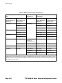
Synchronization Status Messaging with Quality Level Selection . . . . . . . . . . . . . . . . . . . . . . . . . . . . . . .
Timing Reference Selection Based on Quality Level . . . . . . . . . . . . . . . . . . . . . . . . . . . . . . . . . . . . . .
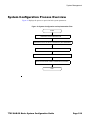
System Configuration Process Overview . . . . . . . . . . . . . . . . . . . . . . . . . . . . . . . . . . . . . . . . . . . . . . . . . . . .
Configuration Notes . . . . . . . . . . . . . . . . . . . . . . . . . . . . . . . . . . . . . . . . . . . . . . . . . . . . . . . . . . . . . . . . . . . .
Reference Sources . . . . . . . . . . . . . . . . . . . . . . . . . . . . . . . . . . . . . . . . . . . . . . . . . . . . . . . . . . . . . . . . . .
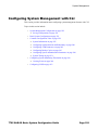
Configuring System Management with CLI. . . . . . . . . . . . . . . . . . . . . . . . . . . . . . . . . . . . . . . . . . . . . . . . . . .
System Management Configuration . . . . . . . . . . . . . . . . . . . . . . . . . . . . . . . . . . . . . . . . . . . . . . . . . . . . . . . .
Saving Configurations . . . . . . . . . . . . . . . . . . . . . . . . . . . . . . . . . . . . . . . . . . . . . . . . . . . . . . . . . . . . . . . .
Basic System Configuration . . . . . . . . . . . . . . . . . . . . . . . . . . . . . . . . . . . . . . . . . . . . . . . . . . . . . . . . . . . . . .
Common Configuration Tasks. . . . . . . . . . . . . . . . . . . . . . . . . . . . . . . . . . . . . . . . . . . . . . . . . . . . . . . . . . . . .
System Information . . . . . . . . . . . . . . . . . . . . . . . . . . . . . . . . . . . . . . . . . . . . . . . . . . . . . . . . . . . . . . . . . .
System Information Parameters . . . . . . . . . . . . . . . . . . . . . . . . . . . . . . . . . . . . . . . . . . . . . . . . . . . . . .
System Time Elements. . . . . . . . . . . . . . . . . . . . . . . . . . . . . . . . . . . . . . . . . . . . . . . . . . . . . . . . . . . . .
Configuring Synchronization and Redundancy . . . . . . . . . . . . . . . . . . . . . . . . . . . . . . . . . . . . . . . . . . . . .
Configuring Synchronization. . . . . . . . . . . . . . . . . . . . . . . . . . . . . . . . . . . . . . . . . . . . . . . . . . . . . . . . .
7705 SAR OS Basic System Configuration Guide
183
184
184
186
186
187
187
189
190
190
191
191
191
192
192
192
193
193
194
195
196
197
197
198
199
201
203
203
204
206
208
210
210
212
213
217
219
220
220
221
222
222
223
224
225
225
227
240
240
Page 5
Table of Contents
Configuring Manual Synchronization . . . . . . . . . . . . . . . . . . . . . . . . . . . . . . . . . . . . . . . . . . . . . . . . . .
Forcing a Switchover . . . . . . . . . . . . . . . . . . . . . . . . . . . . . . . . . . . . . . . . . . . . . . . . . . . . . . . . . . . . . .
Configuring Synchronization Options . . . . . . . . . . . . . . . . . . . . . . . . . . . . . . . . . . . . . . . . . . . . . . . . . .
Configuring ATM Parameters . . . . . . . . . . . . . . . . . . . . . . . . . . . . . . . . . . . . . . . . . . . . . . . . . . . . . . . . . .
Configuring Backup Copies . . . . . . . . . . . . . . . . . . . . . . . . . . . . . . . . . . . . . . . . . . . . . . . . . . . . . . . . . . .
Configuring System Administration Parameters . . . . . . . . . . . . . . . . . . . . . . . . . . . . . . . . . . . . . . . . . . . .
Disconnect . . . . . . . . . . . . . . . . . . . . . . . . . . . . . . . . . . . . . . . . . . . . . . . . . . . . . . . . . . . . . . . . . . . . . .
Set-time . . . . . . . . . . . . . . . . . . . . . . . . . . . . . . . . . . . . . . . . . . . . . . . . . . . . . . . . . . . . . . . . . . . . . . . .
Display-config . . . . . . . . . . . . . . . . . . . . . . . . . . . . . . . . . . . . . . . . . . . . . . . . . . . . . . . . . . . . . . . . . . . .
Tech-support. . . . . . . . . . . . . . . . . . . . . . . . . . . . . . . . . . . . . . . . . . . . . . . . . . . . . . . . . . . . . . . . . . . . .
Save . . . . . . . . . . . . . . . . . . . . . . . . . . . . . . . . . . . . . . . . . . . . . . . . . . . . . . . . . . . . . . . . . . . . . . . . . . .
Reboot . . . . . . . . . . . . . . . . . . . . . . . . . . . . . . . . . . . . . . . . . . . . . . . . . . . . . . . . . . . . . . . . . . . . . . . . .
Post-Boot Configuration Extension Files . . . . . . . . . . . . . . . . . . . . . . . . . . . . . . . . . . . . . . . . . . . . . . .
System Timing . . . . . . . . . . . . . . . . . . . . . . . . . . . . . . . . . . . . . . . . . . . . . . . . . . . . . . . . . . . . . . . . . . . . .
Entering Edit Mode . . . . . . . . . . . . . . . . . . . . . . . . . . . . . . . . . . . . . . . . . . . . . . . . . . . . . . . . . . . . . . . .
Configuring Timing References . . . . . . . . . . . . . . . . . . . . . . . . . . . . . . . . . . . . . . . . . . . . . . . . . . . . . .
Configuring IEEE 1588v2 PTP . . . . . . . . . . . . . . . . . . . . . . . . . . . . . . . . . . . . . . . . . . . . . . . . . . . . . . .
Configuring QL Values for SSM . . . . . . . . . . . . . . . . . . . . . . . . . . . . . . . . . . . . . . . . . . . . . . . . . . . . . .
Using the Revert Command . . . . . . . . . . . . . . . . . . . . . . . . . . . . . . . . . . . . . . . . . . . . . . . . . . . . . . . . .
Other Editing Commands . . . . . . . . . . . . . . . . . . . . . . . . . . . . . . . . . . . . . . . . . . . . . . . . . . . . . . . . . . .
Forcing a Specific Reference . . . . . . . . . . . . . . . . . . . . . . . . . . . . . . . . . . . . . . . . . . . . . . . . . . . . . . . .
Configuring System Monitoring Thresholds . . . . . . . . . . . . . . . . . . . . . . . . . . . . . . . . . . . . . . . . . . . . . . . . . .
Creating Events . . . . . . . . . . . . . . . . . . . . . . . . . . . . . . . . . . . . . . . . . . . . . . . . . . . . . . . . . . . . . . . . . . . .
Configuring LLDP . . . . . . . . . . . . . . . . . . . . . . . . . . . . . . . . . . . . . . . . . . . . . . . . . . . . . . . . . . . . . . . . . . . . . .
System Command Reference . . . . . . . . . . . . . . . . . . . . . . . . . . . . . . . . . . . . . . . . . . . . . . . . . . . . . . . . . . . . .
Command Hierarchies . . . . . . . . . . . . . . . . . . . . . . . . . . . . . . . . . . . . . . . . . . . . . . . . . . . . . . . . . . . . . . .
Command Descriptions . . . . . . . . . . . . . . . . . . . . . . . . . . . . . . . . . . . . . . . . . . . . . . . . . . . . . . . . . . . . . . .
Configuration Commands . . . . . . . . . . . . . . . . . . . . . . . . . . . . . . . . . . . . . . . . . . . . . . . . . . . . . . . . . .
Administration Commands . . . . . . . . . . . . . . . . . . . . . . . . . . . . . . . . . . . . . . . . . . . . . . . . . . . . . . . . . .
Show Commands . . . . . . . . . . . . . . . . . . . . . . . . . . . . . . . . . . . . . . . . . . . . . . . . . . . . . . . . . . . . . . . .
Debug Commands . . . . . . . . . . . . . . . . . . . . . . . . . . . . . . . . . . . . . . . . . . . . . . . . . . . . . . . . . . . . . . . .
Clear Commands . . . . . . . . . . . . . . . . . . . . . . . . . . . . . . . . . . . . . . . . . . . . . . . . . . . . . . . . . . . . . . . . .
240
241
241
242
243
244
244
245
245
247
247
247
248
251
252
252
253
255
258
258
258
260
260
263
265
265
275
276
334
342
389
391
Standards and Protocol Support . . . . . . . . . . . . . . . . . . . . . . . . . . . . . . . . . . . . . . . . . . . . . . . . . . . 393
Page 6
7705 SAR OS Basic System Configuration Guide
List of Tables
Getting Started . . . . . . . . . . . . . . . . . . . . . . . . . . . . . . . . . . . . . . . . . . . . . . . . . . . . . . . . . . . . . . . . . . . 31
Table 1:
Basic Configuration Process . . . . . . . . . . . . . . . . . . . . . . . . . . . . . . . . . . . . . . . . . . . . . . . . . . . . . . 31
Table 2:
7705 SAR-8, 7705 SAR-18, and 7705 SAR-F Comparison . . . . . . . . . . . . . . . . . . . . . . . . . . . . . . . 33
CLI Usage . . . . . . . . . . . . . . . . . . . . . . . . . . . . . . . . . . . . . . . . . . . . . . . . . . . . . . . . . . . . . . . . . . . . . . . 35
Table 3:
Console Control Commands . . . . . . . . . . . . . . . . . . . . . . . . . . . . . . . . . . . . . . . . . . . . . . . . . . . . . . 40
Table 4:
Command Syntax Symbols . . . . . . . . . . . . . . . . . . . . . . . . . . . . . . . . . . . . . . . . . . . . . . . . . . . . . . . 42
Table 5:
CLI Environment Commands . . . . . . . . . . . . . . . . . . . . . . . . . . . . . . . . . . . . . . . . . . . . . . . . . . . . . . 43
Table 6:
CLI Monitor Commands . . . . . . . . . . . . . . . . . . . . . . . . . . . . . . . . . . . . . . . . . . . . . . . . . . . . . . . . . . 44
Table 7:
Online Help Commands . . . . . . . . . . . . . . . . . . . . . . . . . . . . . . . . . . . . . . . . . . . . . . . . . . . . . . . . . . 45
Table 8:
Command Editing Keystrokes
Table 9:
CLI Range Use Limitations . . . . . . . . . . . . . . . . . . . . . . . . . . . . . . . . . . . . . . . . . . . . . . . . . . . . . . . . 53
Table 10:
Pipe/Match Characters . . . . . . . . . . . . . . . . . . . . . . . . . . . . . . . . . . . . . . . . . . . . . . . . . . . . . . . . . . . 55
Table 11:
Special Characters . . . . . . . . . . . . . . . . . . . . . . . . . . . . . . . . . . . . . . . . . . . . . . . . . . . . . . . . . . . . . . 56
Table 12:
Show Alias Output Fields . . . . . . . . . . . . . . . . . . . . . . . . . . . . . . . . . . . . . . . . . . . . . . . . . . . . . . . . . 96
. . . . . . . . . . . . . . . . . . . . . . . . . . . . . . . . . . . . . . . . . . . . . . . . . . . . 51
File System Management . . . . . . . . . . . . . . . . . . . . . . . . . . . . . . . . . . . . . . . . . . . . . . . . . . . . . . . . . . 97
Table 13:
URL Types and Syntax . . . . . . . . . . . . . . . . . . . . . . . . . . . . . . . . . . . . . . . . . . . . . . . . . . . . . . . . . . . 99
Table 14:
File Command Local and Remote File System Support . . . . . . . . . . . . . . . . . . . . . . . . . . . . . . . . . . 99
Boot Options . . . . . . . . . . . . . . . . . . . . . . . . . . . . . . . . . . . . . . . . . . . . . . . . . . . . . . . . . . . . . . . . . . . 121
Table 15:
DHCP DISCOVER Message Options . . . . . . . . . . . . . . . . . . . . . . . . . . . . . . . . . . . . . . . . . . . . . . . 130
Table 16:
DHCP OFFER Message Options . . . . . . . . . . . . . . . . . . . . . . . . . . . . . . . . . . . . . . . . . . . . . . . . . . 131
Table 17:
ADP Instructions . . . . . . . . . . . . . . . . . . . . . . . . . . . . . . . . . . . . . . . . . . . . . . . . . . . . . . . . . . . . . . . 132
Table 18:
Console Configuration Parameter Values . . . . . . . . . . . . . . . . . . . . . . . . . . . . . . . . . . . . . . . . . . . 142
Table 19:
Show BOF Output Fields . . . . . . . . . . . . . . . . . . . . . . . . . . . . . . . . . . . . . . . . . . . . . . . . . . . . . . . . 171
System Management . . . . . . . . . . . . . . . . . . . . . . . . . . . . . . . . . . . . . . . . . . . . . . . . . . . . . . . . . . . . . 175
Table 20:
System-defined Time Zones . . . . . . . . . . . . . . . . . . . . . . . . . . . . . . . . . . . . . . . . . . . . . . . . . . . . . . 178
Table 21:
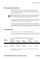
Support Message Rates for Slave and Master Clock States . . . . . . . . . . . . . . . . . . . . . . . . . . . . . 203
Table 22:
Quality Level Values by Interface Type . . . . . . . . . . . . . . . . . . . . . . . . . . . . . . . . . . . . . . . . . . . . . 216
Table 23:
System-defined Time Zones . . . . . . . . . . . . . . . . . . . . . . . . . . . . . . . . . . . . . . . . . . . . . . . . . . . . . . 229
Table 24:
Show System Connections Output Fields . . . . . . . . . . . . . . . . . . . . . . . . . . . . . . . . . . . . . . . . . . . 344
Table 25:
Show System CPU Output Fields . . . . . . . . . . . . . . . . . . . . . . . . . . . . . . . . . . . . . . . . . . . . . . . . . . 345
Table 26:
Show Cron Run History Output Fields . . . . . . . . . . . . . . . . . . . . . . . . . . . . . . . . . . . . . . . . . . . . . . 348
Table 27:
Show Cron Schedule Output Fields . . . . . . . . . . . . . . . . . . . . . . . . . . . . . . . . . . . . . . . . . . . . . . . . 350
Table 28:
Show Cron Script Output Fields . . . . . . . . . . . . . . . . . . . . . . . . . . . . . . . . . . . . . . . . . . . . . . . . . . . 352
Table 29:
Show System Information Output Fields . . . . . . . . . . . . . . . . . . . . . . . . . . . . . . . . . . . . . . . . . . . . 354
7705 SAR OS Basic System Configuration Guide
Page 7
List of Tables
Table 30:
Show Memory Pool Output Fields . . . . . . . . . . . . . . . . . . . . . . . . . . . . . . . . . . . . . . . . . . . . . . . . . 357
Table 31:
Show System NTP Output Fields . . . . . . . . . . . . . . . . . . . . . . . . . . . . . . . . . . . . . . . . . . . . . . . . . . 359
Table 32:
Show System PTP Clock Summary Output Fields . . . . . . . . . . . . . . . . . . . . . . . . . . . . . . . . . . . . . 362
Table 33:
Show System PTP Clock Detail Output Fields . . . . . . . . . . . . . . . . . . . . . . . . . . . . . . . . . . . . . . . . 364
Table 34:
Show System PTP Port Output Fields . . . . . . . . . . . . . . . . . . . . . . . . . . . . . . . . . . . . . . . . . . . . . . 367
Table 35:
Show System PTP Port Peer Detail Output Fields . . . . . . . . . . . . . . . . . . . . . . . . . . . . . . . . . . . . . 370
Table 36:
Show System SNTP Output Fields . . . . . . . . . . . . . . . . . . . . . . . . . . . . . . . . . . . . . . . . . . . . . . . . . 373
Table 37:
Show System Threshold Output Fields . . . . . . . . . . . . . . . . . . . . . . . . . . . . . . . . . . . . . . . . . . . . . 375
Table 38:
Show System Time Output Fields . . . . . . . . . . . . . . . . . . . . . . . . . . . . . . . . . . . . . . . . . . . . . . . . . 377
Table 39:
Show Synchronization Output Fields . . . . . . . . . . . . . . . . . . . . . . . . . . . . . . . . . . . . . . . . . . . . . . . 379
Table 40:
System Uptime Output Fields . . . . . . . . . . . . . . . . . . . . . . . . . . . . . . . . . . . . . . . . . . . . . . . . . . . . . 380
Table 41:
Show Sync-If-Timing Output Fields . . . . . . . . . . . . . . . . . . . . . . . . . . . . . . . . . . . . . . . . . . . . . . . . 381
Table 42:
Show Chassis Output Fields . . . . . . . . . . . . . . . . . . . . . . . . . . . . . . . . . . . . . . . . . . . . . . . . . . . . . 386
Page 8
7705 SAR OS Basic System Configuration Guide
List of Figures
CLI Usage . . . . . . . . . . . . . . . . . . . . . . . . . . . . . . . . . . . . . . . . . . . . . . . . . . . . . . . . . . . . . . . . . . . . . . . 35
Figure 1:
Root Commands . . . . . . . . . . . . . . . . . . . . . . . . . . . . . . . . . . . . . . . . . . . . . . . . . . . . . . . . . . . . . . . . 37
Figure 2:
Operational Root Commands . . . . . . . . . . . . . . . . . . . . . . . . . . . . . . . . . . . . . . . . . . . . . . . . . . . . . . 38
Figure 3:
CLI Display for CLI Tree Help . . . . . . . . . . . . . . . . . . . . . . . . . . . . . . . . . . . . . . . . . . . . . . . . . . . . . . 46
Boot Options . . . . . . . . . . . . . . . . . . . . . . . . . . . . . . . . . . . . . . . . . . . . . . . . . . . . . . . . . . . . . . . . . . . 121
Figure 4:
System Initialization - Part 1 . . . . . . . . . . . . . . . . . . . . . . . . . . . . . . . . . . . . . . . . . . . . . . . . . . . . . . 124
Figure 5:
Files on the Compact Flash . . . . . . . . . . . . . . . . . . . . . . . . . . . . . . . . . . . . . . . . . . . . . . . . . . . . . . 125
Figure 6:
System Initialization - Part 2 . . . . . . . . . . . . . . . . . . . . . . . . . . . . . . . . . . . . . . . . . . . . . . . . . . . . . . 127
Figure 7:
System Initialization With ADP . . . . . . . . . . . . . . . . . . . . . . . . . . . . . . . . . . . . . . . . . . . . . . . . . . . . 128
Figure 8:
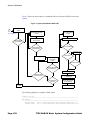
System Startup Flow . . . . . . . . . . . . . . . . . . . . . . . . . . . . . . . . . . . . . . . . . . . . . . . . . . . . . . . . . . . . 134
Figure 9:
7705 SAR Console Port . . . . . . . . . . . . . . . . . . . . . . . . . . . . . . . . . . . . . . . . . . . . . . . . . . . . . . . . . 143
System Management . . . . . . . . . . . . . . . . . . . . . . . . . . . . . . . . . . . . . . . . . . . . . . . . . . . . . . . . . . . . . 175
Figure 10:
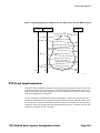
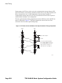
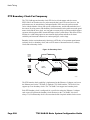
Messaging Sequence Between the PTP Slave Clock and PTP Master Clocks . . . . . . . . . . . . . . . 201
Figure 11:
PTP Slave Clock and Master Clock Synchronization Timing Computation . . . . . . . . . . . . . . . . . . 202
Figure 12:
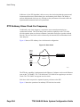
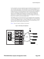
Slave Clock . . . . . . . . . . . . . . . . . . . . . . . . . . . . . . . . . . . . . . . . . . . . . . . . . . . . . . . . . . . . . . . . . . . 204
Figure 13:
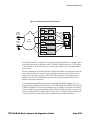
Ordinary Slave Clock Operation . . . . . . . . . . . . . . . . . . . . . . . . . . . . . . . . . . . . . . . . . . . . . . . . . . . 205
Figure 14:
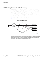
PTP Master Clock . . . . . . . . . . . . . . . . . . . . . . . . . . . . . . . . . . . . . . . . . . . . . . . . . . . . . . . . . . . . . . 206
Figure 15:
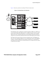
Ordinary Master Clock Operation . . . . . . . . . . . . . . . . . . . . . . . . . . . . . . . . . . . . . . . . . . . . . . . . . . 207
Figure 16:
Boundary Clock . . . . . . . . . . . . . . . . . . . . . . . . . . . . . . . . . . . . . . . . . . . . . . . . . . . . . . . . . . . . . . . 208
Figure 17:
Boundary Clock Operation . . . . . . . . . . . . . . . . . . . . . . . . . . . . . . . . . . . . . . . . . . . . . . . . . . . . . . . 209
Figure 18:
Timing Reference Selection Based on Quality Level . . . . . . . . . . . . . . . . . . . . . . . . . . . . . . . . . . . 214
Figure 19:
System Configuration and Implementation Flow . . . . . . . . . . . . . . . . . . . . . . . . . . . . . . . . . . . . . . 219
7705 SAR OS Basic System Configuration Guide
Page 9
List of Figures
Page 10
7705 SAR OS Basic System Configuration Guide
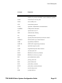
List of Acronyms
Acronym
Expansion
2G
second generation wireless telephone technology
3DES
triple DES (data encryption standard)
3G
third generation mobile telephone technology
5620 SAM
5620 Service Aware Manager
7705 SAR
7705 Service Aggregation Router
7710 SR
7710 Service Router
7750 SR
7750 Service Router
9500 MPR
9500 Microwave Packet Radio
ABR
available bit rate
area border router
AC
alternating current
attachment circuit
ACK
acknowledge
ACL
access control list
ACR
adaptive clock recovery
ADP
automatic discovery protocol
AFI
authority and format identifier
AIS
alarm indication signal
ANSI
American National Standards Institute
Apipe
ATM VLL
APS
automatic protection switching
ARP
address resolution protocol
A/S
active/standby
AS
autonomous system
7705 SAR OS Basic System Configuration Guide
Page 11
List of Acronyms
Page 12
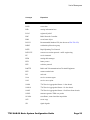
Acronym
Expansion
ASAP
any service, any port
ASBR
autonomous system boundary router
ASN
autonomous system number
ATM
asynchronous transfer mode
ATM PVC
ATM permanent virtual circuit
B3ZS
bipolar with three-zero substitution
Batt A
battery A
B-bit
beginning bit (first packet of a fragment)
Bellcore
Bell Communications Research
BFD
bidirectional forwarding detection
BGP
border gateway protocol
BITS
building integrated timing supply
BMCA
best master clock algorithm
BMU
broadcast, multicast, and unknown traffic
Traffic that is not unicast. Any nature of multipoint traffic:
• broadcast (that is, all 1s as the destination IP to represent all
destinations within the subnet)
• multicast (that is, traffic typically identified by the
destination address, uses special destination address);
for IP, the destination must be 224.0.0.0 to 239.255.255.255
• unknown (that is, the destination is typically a valid unicast
address but the destination port/interface is not yet known;
therefore, traffic needs to be forwarded to all destinations;
unknown traffic is treated as broadcast)
BOF
boot options file
BPDU
bridge protocol data unit
BRAS
Broadband Remote Access Server
BSC
Base Station Controller
BSTA
Broadband Service Termination Architecture
7705 SAR OS Basic System Configuration Guide
List of Acronyms
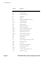
Acronym
Expansion
BTS
base transceiver station
CAS
channel associated signaling
CBN
common bonding networks
CBS
committed buffer space
CC
control channel
continuity check
CCM
continuity check message
CE
customer edge
circuit emulation
CEM
circuit emulation
CES
circuit emulation services
CESoPSN
circuit emulation services over packet switched network
CFM
connectivity fault management
CIDR
classless inter-domain routing
CIR
committed information rate
CLI
command line interface
CLP
cell loss priority
CoS
class of service
CPE
customer premises equipment
Cpipe
circuit emulation (or TDM) VLL
CPM
Control and Processing Module (CPM is used instead of CSM
when referring to CSM filtering to align with CLI syntax used
with other SR products). CSM management ports are referred
to as CPM management ports in the CLI.
CPU
central processing unit
CRC
cyclic redundancy check
CRON
a time-based scheduling service (from chronos = time)
7705 SAR OS Basic System Configuration Guide
Page 13
List of Acronyms
Page 14
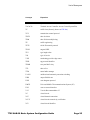
Acronym
Expansion
CSM
Control and Switching Module
CSNP
complete sequence number PDU
CSPF
constrained shortest path first
C-TAG
customer VLAN tag
CV
connection verification
customer VLAN (tag)
CW
control word
DC
direct current
DC-C
DC return - common
DCE
data communications equipment
DC-I
DC return - isolated
DCO
digitally controlled oscillator
DDoS
distributed DoS
DES
data encryption standard
DF
do not fragment
DHB
decimal, hexadecimal, or binary
DHCP
dynamic host configuration protocol
DHCPv6
dynamic host configuration protocol for IPv6
DIS
designated intermediate system
DM
delay measurement
DNS
domain name server
DoS
denial of service
dot1p
IEEE 802.1p bits, found in Ethernet or VLAN ingress packet
headers and used to map traffic to up to eight forwarding
classes
dot1q
IEEE 802.1q encapsulation for Ethernet interfaces
DPI
deep packet inspection
7705 SAR OS Basic System Configuration Guide
List of Acronyms
Acronym
Expansion
DPLL
digital phase locked loop
DSCP
differentiated services code point
DSL
digital subscriber line
DSLAM
digital subscriber line access multiplexer
DTE
data termination equipment
DU
downstream unsolicited
DUID
DHCP unique identifier
DV
delay variation
e911
enhanced 911 service
EAP
Extensible Authentication Protocol
EAPOL
EAP over LAN
E-bit
ending bit (last packet of a fragment)
ECMP
equal cost multi-path
EFM
Ethernet in the first mile
EGP
exterior gateway protocol
EIA/TIA-232
Electronic Industries Alliance/Telecommunications Industry
Association Standard 232 (also known as RS-232)
ELER
egress label edge router
E&M
ear and mouth
earth and magneto
exchange and multiplexer
Epipe
Ethernet VLL
EPL
Ethernet private line
ERO
explicit route object
ESD
electrostatic discharge
ESMC
Ethernet synchronization message channel
ETE
end-to-end
7705 SAR OS Basic System Configuration Guide
Page 15
List of Acronyms
Page 16
Acronym
Expansion
ETH-CFM
Ethernet connectivity fault management (IEEE 802.1ag)
EVDO
evolution - data optimized
EVPL
Ethernet virtual private link
EXP bits
experimental bits (currently known as TC)
FC
forwarding class
FCS
frame check sequence
FDB
forwarding database
FDL
facilities data link
FEAC
far-end alarm and control
FEC
forwarding equivalence class
FF
fixed filter
FIB
forwarding information base
FIFO
first in, first out
FNG
fault notification generator
FOM
figure of merit
FRR
fast reroute
FTN
FEC-to-NHLFE
FTP
file transfer protocol
GFP
generic framing procedure
GigE
Gigabit Ethernet
GRE
generic routing encapsulation
GSM
Global System for Mobile Communications (2G)
HCM
high capacity multiplexing
HDB3
high density bipolar of order 3
HEC
header error control
HMAC
hash message authentication code
7705 SAR OS Basic System Configuration Guide
List of Acronyms
Acronym
Expansion
HSDPA
high-speed downlink packet access
HSPA
high-speed packet access
HVPLS
hierarchical virtual private line service
IANA
internet assigned numbers authority
IBN
isolated bonding networks
ICMP
Internet control message protocol
ICMPv6
Internet control message protocol for IPv6
ICP
IMA control protocol cells
IEEE
Institute of Electrical and Electronics Engineers
IEEE 1588v2
Institute of Electrical and Electronics Engineers standard
1588-2008
IES
Internet Enhanced Service
IETF
Internet Engineering Task Force
IGP
interior gateway protocol
ILER
ingress label edge router
ILM
incoming label map
IMA
inverse multiplexing over ATM
IOM
input/output module
IP
Internet Protocol
IPCP
Internet Protocol Control Protocol
IPIP
IP in IP
Ipipe
IP interworking VLL
IPoATM
IP over ATM
IS-IS
Intermediate System-to-Intermediate System
IS-IS-TE
IS-IS-traffic engineering (extensions)
ISO
International Organization for Standardization
7705 SAR OS Basic System Configuration Guide
Page 17
List of Acronyms
Page 18
Acronym
Expansion
LB
loopback
lbf-in
pound force inch
LBM
loopback message
LBO
line buildout
LBR
loopback reply
LCP
link control protocol
LDP
label distribution protocol
LER
label edge router
LFIB
label forwarding information base
LIB
label information base
LLDP
link layer discovery protocol
LLDPDU
link layer discovery protocol data unit
LLF
link loss forwarding
LLID
loopback location ID
LM
loss measurement
LSA
link-state advertisement
LSDB
link-state database
LSP
label switched path
link-state PDU (for IS-IS)
LSR
label switch router
link-state request
LSU
link-state update
LT
linktrace
LTE
line termination equipment
LTM
linktrace message
LTN
LSP ID to NHLFE
7705 SAR OS Basic System Configuration Guide
List of Acronyms
Acronym
Expansion
LTR
linktrace reply
MA
maintenance association
MAC
media access control
MA-ID
maintenance association identifier
MBB
make-before-break
MBS
maximum buffer space
maximum burst size
media buffer space
MBSP
mobile backhaul service provider
MC-MLPPP
multi-class multilink point-to-point protocol
MD
maintenance domain
MD5
message digest version 5 (algorithm)
MDA
media dependent adapter
MDDB
multidrop data bridge
MDL
maintenance data link
ME
maintenance entity
MED
multi-exit discriminator
MEF
Metro Ethernet Forum
MEG
maintenance entity group
MEG-ID
maintenance entity group identifier
MEN
Metro Ethernet network
MEP
maintenance association end point
MFC
multi-field classification
MHF
MIP half function
MIB
management information base
MIP
maintenance association intermediate point
7705 SAR OS Basic System Configuration Guide
Page 19
List of Acronyms
Page 20
Acronym
Expansion
MIR
minimum information rate
MLPPP
multilink point-to-point protocol
MP
merge point
multilink protocol
MP-BGP
multiprotocol border gateway protocol
MPLS
multiprotocol label switching
MPR
see 9500 MPR
MRRU
maximum received reconstructed unit
MRU
maximum receive unit
MSDU
MAC Service Data Unit
MS-PW
multi-segment pseudowire
MTIE
maximum time interval error
MTSO
mobile trunk switching office
MTU
maximum transmission unit
multi-tenant unit
M-VPLS
management virtual private line service
MW
microwave
N.m
newton meter
NBMA
non-broadcast multiple access (network)
NE
network element
NET
network entity title
NHLFE
next hop label forwarding entry
NHOP
next-hop
NLRI
network layer reachability information
NNHOP
next next-hop
NNI
network-to-network interface
7705 SAR OS Basic System Configuration Guide
List of Acronyms
Acronym
Expansion
Node B
similar to BTS but used in 3G networks — term is used in
UMTS (3G systems) while BTS is used in GSM (2G systems)
NSAP
network service access point
NSSA
not-so-stubby area
NTP
network time protocol
OAM
operations, administration, and maintenance
OAMPDU
OAM protocol data units
OC3
optical carrier, level 3
ORF
outbound route filtering
OS
operating system
OSI
Open Systems Interconnection (reference model)
OSINLCP
OSI Network Layer Control Protocol
OSPF
Open Shortest Path First
OSPF-TE
OSPF-traffic engineering (extensions)
OSS
operations support system
OSSP
Organization Specific Slow Protocol
OTP
one time password
PADI
PPPoE active discovery initiation
PADR
PPPoE active discovery request
PAE
port authentication entities
PCP
priority point code
PDU
protocol data units
PDV
packet delay variation
PDVT
packet delay variation tolerance
PE
provider edge router
PHB
per-hop behavior
7705 SAR OS Basic System Configuration Guide
Page 21
List of Acronyms
Page 22
Acronym
Expansion
PHY
physical layer
PID
protocol ID
PIR
peak information rate
PLCP
Physical Layer Convergence Protocol
PLR
point of local repair
POP
point of presence
POS
packet over SONET
PPP
point-to-point protocol
PPPoE
point-to-point protocol over Ethernet
PRC
primary reference clock
PSN
packet switched network
PSNP
partial sequence number PDU
PTP
precision time protocol
performance transparency protocol
PVC
permanent virtual circuit
PVCC
permanent virtual channel connection
PW
pseudowire
PWE
pseudowire emulation
PWE3
pseudowire emulation edge-to-edge
QL
quality level
QoS
quality of service
RADIUS
Remote Authentication Dial In User Service
RAN
Radio Access Network
RBS
robbed bit signaling
RD
route distinguisher
RDI
remote defect indication
7705 SAR OS Basic System Configuration Guide
List of Acronyms
Acronym
Expansion
RED
random early discard
RESV
reservation
RIB
routing information base
RJ-45
registered jack 45
RNC
Radio Network Controller
RRO
record route object
RS-232
Recommended Standard 232 (also known as EIA/TIA-232)
RSHG
residential split horizon group
RSTP
Rapid Spanning Tree Protocol
RSVP-TE
resource reservation protocol - traffic engineering
RT
receive/transmit
RTM
routing table manager
RTN
battery return
RTP
real-time protocol
R&TTE
Radio and Telecommunications Terminal Equipment
RTU
remote terminal unit
RU
rack unit
SAA
service assurance agent
SAP
service access point
SAR-8
7705 Service Aggregation Router - 8-slot chassis
SAR-18
7705 Service Aggregation Router - 18-slot chassis
SAR-F
7705 Service Aggregation Router - fixed form-factor chassis
SAToP
structure-agnostic TDM over packet
SCADA
surveillance, control and data acquisition
SCP
secure copy
SD
signal degrade
7705 SAR OS Basic System Configuration Guide
Page 23
List of Acronyms
Page 24
Acronym
Expansion
SDH
synchronous digital hierarchy
SDI
serial data interface
SDP
service destination point
SE
shared explicit
SF
signal fail
SFP
small form-factor pluggable (transceiver)
SGT
self-generated traffic
SHA-1
secure hash algorithm
SHG
split horizon group
SIR
sustained information rate
SLA
Service Level Agreement
SNMP
Simple Network Management Protocol
SNPA
subnetwork point of attachment
SNTP
simple network time protocol
SONET
synchronous optical networking
S-PE
switching provider edge router
SPF
shortest path first
SPT
shortest path tree
SR
service router (includes 7710 SR, 7750 SR)
SRLG
shared risk link group
SSH
secure shell
SSM
synchronization status messaging
SSU
system synchronization unit
S-TAG
service VLAN tag
STM1
synchronous transport module, level 1
SVC
switched virtual circuit
7705 SAR OS Basic System Configuration Guide
List of Acronyms
Acronym
Expansion
SYN
synchronize
TACACS+
Terminal Access Controller Access-Control System Plus
TC
traffic class (formerly known as EXP bits)
TCP
transmission control protocol
TDEV
time deviation
TDM
time division multiplexing
TE
traffic engineering
TFTP
trivial file transfer protocol
TLDP
targeted LDP
TLV
type length value
ToS
type of service
T-PE
terminating provider edge router
TPID
tag protocol identifier
TPMR
two-port MAC relay
TTL
time to live
TTM
tunnel table manager
U-APS
unidirectional automatic protection switching
UBR
unspecified bit rate
UDP
user datagram protocol
UMTS
Universal Mobile Telecommunications System (3G)
UNI
user-to-network interface
V.35
V-series Recommendation 35
VC
virtual circuit
VCC
virtual channel connection
VCCV
virtual circuit connectivity verification
VCI
virtual circuit identifier
7705 SAR OS Basic System Configuration Guide
Page 25
List of Acronyms
Page 26
Acronym
Expansion
VID
VLAN ID
VLAN
virtual LAN
VLL
virtual leased line
VoIP
voice over IP
Vp
peak voltage
VP
virtual path
VPC
virtual path connection
VPI
virtual path identifier
VPLS
virtual private LAN service
VPN
virtual private network
VPRN
virtual private routed network
VRF
virtual routing and forwarding table
VSE
vendor-specific extension
VSO
vendor-specific option
WCDMA
wideband code division multiple access (transmission protocol
used in UMTS networks)
WRED
weighted random early discard
WTR
wait to restore
7705 SAR OS Basic System Configuration Guide
Preface
About This Guide
This guide describes system concepts and provides configuration explanations and examples
to configure the 7705 SAR boot option file (BOF) and perform system and file management
functions.
This guide is organized into functional chapters and provides concepts and descriptions of
the implementation flow, as well as Command Line Interface (CLI) syntax and command
usage.
Audience
This guide is intended for network administrators who are responsible for configuring
7705 SAR routers. It is assumed that the network administrators have an understanding of
networking principles and configurations. Protocols, standards, and processes described in
this guide include the following:
•
CLI concepts
•
file system concepts
•
boot option, configuration, image loading, and initialization procedures
•
basic system management functions such as the system name, router location and
coordinates, and CLLI code, time zones, Network Time Protocol (NTP), Simple
Network Time Protocol (SNTP), and synchronization properties
7705 SAR OS Basic System Configuration Guide
Page 27
Preface
List of Technical Publications
The 7705 SAR OS documentation set is composed of the following guides:
•
7705 SAR OS Basic System Configuration Guide
This guide describes basic system configurations and operations.
•
7705 SAR OS System Management Guide
This guide describes system security and access configurations as well as event
logging and accounting logs.
•
7705 SAR OS Interface Configuration Guide
This guide describes card and port provisioning.
•
7705 SAR OS Router Configuration Guide
This guide describes logical IP routing interfaces, IP-based filtering, and routing
policies.
•
7705 SAR OS MPLS Guide
This guide describes how to configure Multiprotocol Label Switching (MPLS),
Resource Reservation Protocol for Traffic Engineering (RSVP-TE), and Label
Distribution Protocol (LDP).
•
7705 SAR OS Services Guide
This guide describes how to configure service parameters such as service access
points (SAPs), service destination points (SDPs), customer information, and user
services.
•
7705 SAR OS Quality of Service Guide
This guide describes how to configure Quality of Service (QoS) policy
management.
•
7705 SAR OS Routing Protocols Guide
This guide provides an overview of dynamic routing concepts and describes how to
configure them.
•
7705 SAR OS OAM and Diagnostics Guide
This guide provides information on Operations, Administration and Maintenance
(OAM) tools.
Page 28
7705 SAR OS Basic System Configuration Guide
Preface
Multiple PDF File Search
You can use Adobe Reader, Release 6.0 or later, to search multiple PDF files for a term.
Adobe Reader displays the results in a display panel. The results are grouped by PDF file.
You can expand the entry for each file.
Note: The PDF files in which you search must be in the same folder.
To search multiple PDF files for a term:
Step 1. Open Adobe Reader.
Step 2. Choose Edit – Search from the Adobe Reader main menu. The Search panel appears.
Step 3. Enter the term to search for.
Step 4. Select the All PDF Documents in radio button.
Step 5. Choose the folder in which to search using the drop-down menu.
Step 6. Select the following criteria if required:
•
Whole words only
•
Case-Sensitive
•
Include Bookmarks
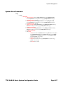
•
Include Comments
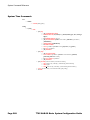
Step 7. Click on the Search button.
Adobe Reader displays the search results. You can expand the entries for each file by
clicking on the + symbol.
Step 8. Click on a search result to go directly to that location in the selected file.
Technical Support
If you purchased a service agreement for your 7705 SAR router and related products from a
distributor or authorized reseller, contact the technical support staff for that distributor or
reseller for assistance. If you purchased an Alcatel-Lucent service agreement, contact your
welcome center at:
Web: http://support.alcatel-lucent.com
7705 SAR OS Basic System Configuration Guide
Page 29
Preface
Page 30
7705 SAR OS Basic System Configuration Guide
Getting Started
In This Chapter
This chapter provides process flow information to configure basic router and system
parameters, perform operational functions with directory and file management, and perform
boot option tasks.
Alcatel-Lucent 7705 SAR System Configuration
Process
Table 1 lists the tasks necessary to perform system and file management functions and to
configure boot option files (BOF).
Each chapter in this book is presented in an overall logical configuration flow. Each section
describes a software area and provides CLI syntax and command usage to configure
parameters for a functional area.
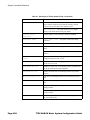
Table 1: Basic Configuration Process
Area
Task
Chapter
CLI Usage
Learning the CLI structure
CLI Usage on page 35
Basic CLI commands
Basic CLI Commands on page 40
Configure environment commands
CLI Environment Commands on page 43
Configure monitor commands
CLI Monitor Commands on page 43
Operational
functions
Directory and file management
File System Management on page 97
Boot options
Configure boot option files (BOF)
Boot Options on page 121
7705 SAR OS Basic System Configuration Guide
Page 31
Getting Started
Table 1: Basic Configuration Process (Continued)
Area
Task
Chapter
System
configuration
Configure system functions, including host
name, address, domain name, and time
parameters
System Management on page 175
Reference
List of IEEE, IETF, and other proprietary
entities
Standards and Protocol Support on page
393
Page 32
7705 SAR OS Basic System Configuration Guide
Getting Started
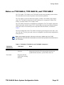
Notes on 7705 SAR-8, 7705 SAR-18, and 7705 SAR-F
The 7705 SAR-8, 7705 SAR-18, and 7705 SAR-F run the same operating system software.
The main difference between the products is their hardware platforms.
The 7705 SAR-8 is an 8-slot chassis that supports 2 CSMs, a Fan module, and 6 adapter
cards. The 7705 SAR-18 chassis has 18 slots; in Release 4.0, it supports 2 CSMs, a Fan
module, an Alarm module, and 12 adapter cards.
The 7705 SAR-F chassis has a fixed hardware configuration. The 7705 SAR-F replaces the
CSM, Fan module, and the 16-port T1/E1 ASAP Adapter card and 8-port Ethernet Adapter
card with an all-in-one unit that provides comparable functional blocks, as detailed in
Table 2.
The fixed configuration of the 7705 SAR-F means that provisioning the router at the “card
slot” and “type” levels is preset and is not user-configurable. Operators begin configurations
at the port level.
Note: Unless stated otherwise, references to the terms “Adapter card” and “CSM”
throughout the 7705 SAR OS documentation set include the equivalent functional blocks on
the 7705 SAR-F.
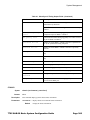
Table 2: 7705 SAR-8, 7705 SAR-18, and 7705 SAR-F Comparison
7705 SAR-8,
7705 SAR-18
7705 SAR-F
Notes
CSM
Control and switching
functions
The control and switching functions include the console and
management interfaces, the alarm and fan functions, the
synchronization interfaces, system LEDs, and so on.
Fan module
Integrated with the
control and switching
functions
7705 SAR OS Basic System Configuration Guide
Page 33
Getting Started
Table 2: 7705 SAR-8, 7705 SAR-18, and 7705 SAR-F Comparison (Continued)
7705 SAR-8,
7705 SAR-18
7705 SAR-F
Notes
16-port T1/E1 ASAP
Adapter card
16 individual T1/E1
ports on the faceplate
The T1/E1 ports on the 7705 SAR-F are equivalent to the
T1/E1 ports on the 16-port T1/E1 ASAP Adapter card,
version 1, except that the 16 T1/E1 ports on the 7705 SAR-F
support multiple synchronization sources to support two
timing references. The 16-port T1/E1 ASAP Adapter card,
version 2, also supports two timing references.
On the 7705 SAR-8 and 7705 SAR-18, the CLI indicates the
MDA type for the 16-port T1/E1 ASAP Adapter card as
a16-chds1 for version 1 and a16-chds1v2 for version
2.
On the 7705 SAR-F, the CLI indicates the MDA type for the
7705 SAR-F ports as i16-chds1.
8-port Ethernet
Adapter card
8 individual Ethernet
ports on the faceplate
The –48 VDC versions of the 7705 SAR-8 support two
versions of the 8-port Ethernet Adapter card, with version 2
having additional support for Synchronous Ethernet.
The +24 VDC version of the 7705 SAR-8 supports only
version 2 of the 8-port Ethernet Adapter card.
The 7705 SAR-18 supports only version 2 of the card.
The Ethernet ports on the 7705 SAR-F are functionally
equivalent to the Ethernet ports on version 2 of the 8-port
Ethernet Adapter card and support multiple synchronization
sources to support two timing references.
On the 7705 SAR-8, the CLI indicates the MDA type for the
8-port Ethernet Adapter card as a8-eth or a8-ethv2. On
the 7705 SAR-18, the CLI indicates the MDA type as
a8-ethv2. On the 7705 SAR-F, the CLI indicates the MDA
type for the 7705 SAR-F Ethernet ports as i8-eth.
Requires user
configuration at card
(IOM) and MDA
(adapter card) levels
Configuration at card
(IOM) and MDA
(adapter card) levels
is preset and users
cannot change these
types
Page 34
7705 SAR OS Basic System Configuration Guide
CLI Usage
In This Chapter
This chapter provides information about using the Command Line Interface (CLI).
Topics in this chapter include:
•
CLI Structure on page 36
•
Navigating in the CLI on page 39
→ CLI Contexts on page 39
→ Basic CLI Commands on page 40
→ CLI Environment Commands on page 43
→ CLI Monitor Commands on page 43
•
Getting Help in the CLI on page 45
•
The CLI Command Prompt on page 47
•
Displaying Configuration Contexts on page 48
•
EXEC Files on page 49
•
Entering CLI Commands on page 50
→ Command Completion on page 50
→ Unordered Parameters on page 50
→ Editing Keystrokes on page 51
→ Absolute Paths on page 52
→ History on page 52
→ Entering Numerical Ranges on page 53
→ Pipe/Match on page 54
→ Redirection on page 56
•
Basic Command Reference on page 59
7705 SAR OS Basic System Configuration Guide
Page 35
CLI Structure
CLI Structure
Alcatel-Lucent’s 7705 SAR Operating System (OS) CLI is a command-driven interface
accessible through the console, Telnet, and secure shell (SSH). The CLI can be used for
configuration and management of 7705 SAR routers.
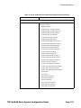
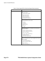
The 7705 SAR CLI command tree is a hierarchical inverted tree. At the highest level is the
ROOT level. Below this level are other tree levels with the major command groups; for
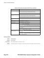
example, configuration commands and show commands are levels below ROOT.
The CLI is organized so that related commands with the same scope are at the same level or
in the same context. Sublevels or subcontexts have related commands with a more refined
scope.
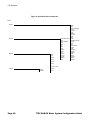
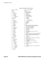
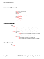
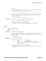
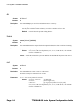
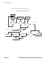
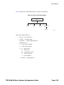
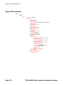
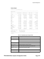
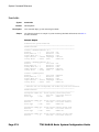
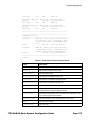
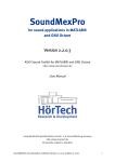
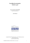
Figure 1 and Figure 2 display the major contexts for router configuration.
Page 36
7705 SAR OS Basic System Configuration Guide
CLI Usage
Figure 1: Root Commands
ROOT
ADMIN
BOF
CONFIGURE
card
cron
eth-cfm
filter
log
port
qos
redundancy
router
saa
service
system
ENVIRONMENT
alias
create
more
reduced-prompt
saved-ind-prom
terminal
time-display
time-stamp
FILE
MONITOR
HELP
address
autonegotiate
console-speed
dns-domain
duplex
persist
primary-config
primary-dns
primary-image
save
secondary-config
secondary-dns
secondary-image
speed
static-route
tertiary-config
tertiary-dns
tertiary-image
wait
debug-save
disconnect
display-config
enable-tech
radius-disc
reboot
redundancy
save
set-time
tech-support
filter
port
router
service
management-access-filter
help
help edit
help globals
attrib
cd
copy
delete
dir
format
md
move
rd
repair
scp
shutdown
type
version
PASSWORD
7705 SAR OS Basic System Configuration Guide
Page 37
CLI Structure
Figure 2: Operational Root Commands
ROOT
SHOW
CLEAR
DEBUG
oam
ppp
radius
router
application-assur
card
cpu-protection
cron
filter
log
mda
port
radius
router
saa
screen
service
system
tacplus
trace
alias
bof
boot-messages
card
chassis
cron
debug
eth-cfm
filter
log
mda
multilink-bundle
pools
port
qos
redundancy
router
saa
service
snmp
system
time
trace
uptime
users
version
service
snmp
sync-if-timing
TOOLS
Page 38
dump
perform
system
trace
7705 SAR OS Basic System Configuration Guide
CLI Usage
Navigating in the CLI
The following sections describe additional navigational and syntax information:
•
CLI Contexts
•
Basic CLI Commands
•
CLI Environment Commands
•
CLI Monitor Commands
CLI Contexts
Use the CLI to access, configure, and manage Alcatel-Lucent’s 7705 SAR routers. CLI
commands are entered at the command line prompt. Access to specific CLI commands is
controlled by the permissions set by your system administrator. Entering a CLI command
makes navigation possible from one command context (or level) to another. When you
initially enter a CLI session, you are in the ROOT context. Navigate to another level by
entering the name of successively lower contexts. For example, enter either the configure
or show commands at the ROOT context to navigate to the config or show context,
respectively. For example, at the command prompt, enter config. The active CSM slot
displays in the command prompt at the beginning of the CLI context.
A:ALU-12# config
A:ALU-12>config#
In a given CLI context, you can enter commands at that context level by simply entering the
text. It is also possible to include a command in a lower context as long as the command is
formatted in the proper command and parameter syntax.
The following example shows two methods of navigating to a service SDP ingress level:
Method 1: Enter all commands on a single line.
A:ALU-12# configure service cpipe 6 spoke-sdp 2:6 ingress
*A:ALU-12>config>service>cpipe>spoke-sdp>ingress#
Method 2: Enter each command on a separate line.
A:ALU-12>config# service
A:ALU-12>config>service# cpipe 6
*A:ALU-12>config>service>cpipe# spoke-sdp 2:6
*A:ALU-12>config>service>cpipe>spoke-sdp# ingress
*A:ALU-12>config>service>cpipe>spoke-sdp>ingress#
The CLI returns an error message if the syntax is incorrect.
*A:ALU-12>config# rooter
Error: Bad command.
7705 SAR OS Basic System Configuration Guide
Page 39
Navigating in the CLI
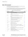
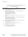
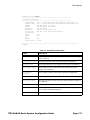
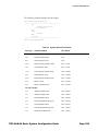
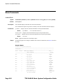
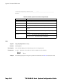
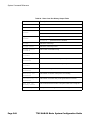
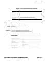
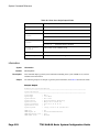
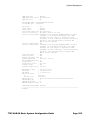
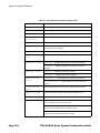
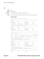
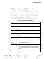
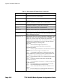
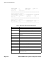
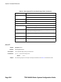
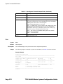
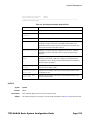
Basic CLI Commands
The console control commands are the commands that are used for navigating within the
CLI and displaying information about the console session.
Most of these commands are implemented as global commands. They can be entered at any
level in the CLI hierarchy, with the exception of the password command, which must be
entered at the ROOT level. The console control commands are listed in Table 3.
Table 3: Console Control Commands
Page 40
Command
Description
Page
<Ctrl-c>
Aborts the pending command
<Ctrl-z>
Terminates the pending command line and returns to the ROOT
context
back
Navigates the user to the parent context
63
clear
Clears statistics for a specified entity or clears and resets the
entity
63
echo
Echoes the text that is typed in. Primary use is to display
messages to the screen within an exec file.
64
exec
Executes the contents of a text file as if they were CLI
commands entered at the console
64
exit
Returns the user to the previous higher context
64
exit all
Returns the user to the ROOT context
66
help
Displays help in the CLI
66
?
Displays all available options
history
Displays a list of the most recently entered commands
67
info
Displays the running configuration for a configuration context
68
logout
Terminates the CLI session
69
oam
Provides OAM test suite options. See the 7705 SAR OS OAM
and Diagnostics Guide.
password
Changes the user CLI login password. The password can only
be changed at the ROOT level.
69
ping
Verifies the reachability of a remote host
70
7705 SAR OS Basic System Configuration Guide
CLI Usage
Table 3: Console Control Commands (Continued)
Command
Description
Page
pwc
Displays the present or previous working context of the CLI
session
72
sleep
Causes the console session to pause operation (sleep) for 1
second or for the specified number of seconds. Primary use is to
introduce a pause within the execution of an exec file.
72
ssh
Opens a secure shell connection to a host
73
telnet
Telnets to a host
73
traceroute
Determines the route to a destination address
74
tree
Displays a list of all commands at the current level and all
sublevels
75
write
Sends a console message to a specific user or to all users with
active console sessions
75
The list of all system global commands is displayed by entering help globals in the
CLI. For example:
*A:ALU-12>config>service# help globals
back
- Go back a level in the command tree
echo
- Echo the text that is typed in
enable-admin
- Enable the user to become a system administrator
exec
- Execute a file - use -echo to show the commands and
prompts on the screen
exit
- Exit to intermediate mode - use option all to exit to
root prompt
help
- Display help
history
- Show command history
info
- Display configuration for the present node
logout
- Log off this system
oam
+ OAM Test Suite
ping
- Verify the reachability of a remote host
pwc
- Show the present working context
sleep
- Sleep for specified number of seconds
ssh
- SSH to a host
telnet
- Telnet to a host
traceroute
- Determine the route to a destination address
tree
- Display command tree structure from the context of
execution
write
- Write text to another user
*A:ALU-12>config>service#
7705 SAR OS Basic System Configuration Guide
Page 41
Navigating in the CLI
Table 4 lists command syntax symbols. Where the syntax differs between the CLI and the
Command Reference sections of the 7705 SAR guides is noted in the table.
Table 4: Command Syntax Symbols
Symbol
Description
Example
A vertical line (pipe) indicates that one of the
parameters within the brackets or braces is required
tcp-ack {true | false}
[]
Brackets indicate optional parameters
router [router-name]
<>
Angle brackets indicate that the user must enter a
value for the parameter inside the brackets (Note:
angle brackets are not used in the Command
Reference section but are used on the CLI; italics are
used in the Command Reference section to indicate
the same rule)
interface <interface-name>
{}
Braces indicate that one of the parameters must be
selected
default-action {drop | forward}
[{ }]
Braces within square brackets indicate that the
parameters are optional, but if one is selected, the
information within the braces is required; for
example, if you select the peer parameter, you must
enter the keyword “peer” (ip-address is optional)
discovery [{peer [ip-address]} |
{interface [ip-int-name]}]
Bold
In the Command Reference section (not on the CLI),
bold indicates commands and keywords that the user
must enter exactly as shown
scope {inclusive | template}
Italic
In the Command Reference section (not on the CLI),
italics indicate parameters that the user must enter a
value for
dscp dscp-name
n/a
In the Command Reference section, n/a in the
Default field of a command indicates that a default
value is not applicable for the command
|
Page 42
7705 SAR OS Basic System Configuration Guide
CLI Usage
CLI Environment Commands
The CLI environment commands are found in the root>environment context of the
CLI tree. These commands control session preferences for a single CLI session. The CLI
environment commands are listed in Table 5.
Table 5: CLI Environment Commands
Command
Description
Page
alias
Enables the substitution of a command line by an alias
76
create
Enables or disables the use of a create parameter check
76
more
Configures whether CLI output should be displayed one
screen at a time awaiting user input to continue
77
reducedprompt
Configures the maximum number of higher-level CLI context
nodes to display by name in the CLI prompt for the current
CLI session
77
saved-indprompt
Saves the indicator in the prompt
78
terminal
Configures the terminal screen length for the current CLI
session
78
time-display
Specifies whether time should be displayed in local time or
UTC
79
time-stamp
Specifies whether a timestamp should be displayed before the
prompt
79
CLI Monitor Commands
The CLI monitor commands are found in the root>monitor context of the CLI tree.
Monitor commands display specified statistical information related to the monitor subject
(such as filter, port, router, and service) at a configurable interval until a count is reached.
The monitor command output displays a snapshot of the current statistics. The output
display refreshes with subsequent statistical information at each configured interval and is
displayed as a delta to the previous display.
The <Ctrl-c> keystroke interrupts a monitoring process. Monitor command
configurations cannot be saved. You must enter the command for each monitoring session.
If the maximum limits are configured, you can monitor the statistical information for a
maximum of 60 × 999 s (approximately 1000 minutes, or 16.6 hours).
7705 SAR OS Basic System Configuration Guide
Page 43
Navigating in the CLI
The CLI monitor commands are listed in Table 6.
Table 6: CLI Monitor Commands
Page 44
Command
Description
Page
filter
Enables IP and MAC filter monitoring at a configurable
interval until that count is reached
80
managementaccess-filter
Monitors commands for management access filters
82
port
Enables port traffic monitoring. The specified port(s)
statistical information displays at the configured interval
until the configured count is reached.
84
router
Enables virtual router instance monitoring at a
configurable interval until that count is reached
87
service
Monitors commands for a particular service
92
7705 SAR OS Basic System Configuration Guide
CLI Usage
Getting Help in the CLI
The help system commands and the ? key display different types of help in the CLI.
Table 7 lists the help commands.
Table 7: Online Help Commands
Command
Description
?
Lists all commands in the current context
string ?
Lists all commands available in the current context that start
with string
command ?
Displays the command’s syntax and associated keywords
command keyword ?
Lists the associated arguments for keyword in command
string<Tab>
string<Space>
Completes a partial command name (auto-completion) or lists
available commands that match string
The tree and tree detail system commands are help commands that are useful when
searching for a command in a lower-level context.
Figure 3 displays a partial list of the tree and tree detail command output entered at
the config level.
7705 SAR OS Basic System Configuration Guide
Page 45
Getting Help in the CLI
Figure 3: CLI Display for CLI Tree Help
*A:ALU-12>config# tree
configure
+---card
| +---card-type
| +---mda
| | +---clock-mode
| | +---mda-type
| | +---network
| | | +---ingress
| | | | +---queue-policy
| | +---shutdown
| +---shutdown
+---cron
| +---action
| | +---expire-time
| | +---lifetime
| | +---max-completed
| | +---results|
| | +---script
| | +---shutdown
| +---schedule
| | +---action|
| | +---count
| | +---day-of-month
| | +---description
| | +---end-time
| | +---hour
| | +---interval
| | +---minute
| | +---month
| | +---shutdown
| | +---type
| | +---weekday
| +---script
| | +---description
| | +---location
| | +---shutdown
+---filter
| +---ip-filter
| | +---default-action
| | +---description
| | +---entry
| | | +---action
| | | +---description
| | | +---match
| | | | +---dst-ip
| | | | +---dst-port
| | | | +---icmp-code
| | | | +---icmp-type
| | | | +---src-ip
| | | | +---src-port
| | +---renum
| | +---scope
Page 46
*A:ALU-12>config# tree detail
configure
+---card <slot-number>
| no card <slot-number>
| +---card-type <card-type>
| | no card-type
| +---mda <mda-slot>
| | no mda <mda-slot>
| | +---clock-mode adaptive
| | +---mda-type <mda-type>
| | | no mda-type
| | +---network
| | | +---ingress
| | | | +---no queue-policy
| | | | | queue-policy <name>
| | +---no shutdown
| | | shutdown
| +---no shutdown
| | shutdown
+---cron
| +---action <action-name> [owner <action-owner>]
| | no action <action-name> [owner <action-owner>]
| | +---expire-time {<seconds>|forever}
| | +---lifetime {<seconds>|forever}
| | +---max-completed <unsigned>
| | +---no results
| | | results <file-url>
| | +---no script
| | | script <script-name> [owner <script-owner>]
| | +---no shutdown
| | | shutdown
| +---no schedule <schedule-name> [owner <schedule-owner>]
| | schedule <schedule-name> [owner <schedule-owner>]
| | +---action <action-name> [owner <action-owner>]
| | | no action
| | +---count <number>
| | | no count
| | +---day-of-month {<day-number> [..<day-number>]|all}
| | | no day-of-month
| | +---description <description-string>
| | | no description
| | +---end-time [<date>|<day-name>] <time>
| | | no end-time
| | +---hour {<hour-number> [..<hour-number>]|all}
| | | no hour
| | +---interval <seconds>
| | | no interval
| | +---minute {<minute-number> [..<minute-number>]|all}
| | | no minute
7705 SAR OS Basic System Configuration Guide
CLI Usage
The CLI Command Prompt
By default, the CLI command prompt indicates the device being accessed and the current
CLI context. For example, the prompt: A:ALU-1>config>router# indicates that the
active CSM is CSM A, the user is on the device with hostname ALU-1, and the current
context is configure router. In the prompt, the separator used between contexts is the
“>” symbol.
At the end of the prompt, there is either a pound sign (#) or a dollar sign ($). A # at the end
of the prompt indicates that the context is an existing context. A $ at the end of the prompt
indicates that the context has been newly created. New contexts are newly created for logical
entities when the user first navigates into the context.
Since there can be a large number of sublevels in the CLI, the system command reducedprompt #_of_levels allows the user to control the number of levels displayed in the
prompt.
All special characters (#, $, and so on) must be enclosed within double quotes; otherwise, the
character is seen as a comment character and all characters on the command line following
the # are ignored. For example:
*A:ALU-1>config>router>mpls# authentication-key "router#1"
This example shows a security configuration over a network link. Because the string
“router#1” is enclosed within double quotes, it is recognized as a password for the link.
When changes are made to the configuration file, a “*” appears in the prompt string
(*A:ALU-1) indicating that the changes have not been saved. When an admin save
command is executed the “*” disappears. This behavior is controlled in the saved-indprompt command in the environment context.
7705 SAR OS Basic System Configuration Guide
Page 47
Displaying Configuration Contexts
Displaying Configuration Contexts
The info and info detail commands display the configuration for the current level.
The info command displays non-default configurations. The info detail command
displays the entire configuration for the current level, including defaults. The following
example shows the output that displays using the info command and the output that
displays using the info detail command.
*A:ALU-1>config>router# interface system
*A:ALU-1>config>router>if# info
---------------------------------------------address 10.221.221.72/32
---------------------------------------------*A:ALU-1>config>router>if#
*A:ALU-1>config>router>if# info detail
---------------------------------------------address 10.221.221.72/32
no description
no arp-timeout
icmp
mask-reply
unreachables 100 10
ttl-expired 100 10
exit
no ntp-broadcast
no shutdown
no bfd
---------------------------------------------*A:ALU-1>config>router>if#
Page 48
7705 SAR OS Basic System Configuration Guide
CLI Usage
EXEC Files
The exec command allows you to execute a text file of CLI commands as if it were typed at
a console device.
The exec command and the associated exec files can be used to conveniently execute a
number of commands that are always executed together in the same order. For example, an
exec command can be used to define a set of commonly used standard command aliases.
The echo command can be used within an exec command file to display messages on
screen while the file executes.
7705 SAR OS Basic System Configuration Guide
Page 49
Entering CLI Commands
Entering CLI Commands
The following sections describe additional information on entering CLI commands:
•
Command Completion
•
Unordered Parameters
•
Editing Keystrokes
•
Absolute Paths
•
History
•
Entering Numerical Ranges
•
Pipe/Match
•
Redirection
Command Completion
The CLI supports both command abbreviation and command completion. If the keystrokes
entered are enough to match a valid command, the CLI displays the remainder of the
command syntax when the <Tab> key or spacebar is pressed. When typing a command, the
<Tab> key or spacebar invokes auto-completion. If the keystrokes entered are sufficient to
identify a specific command, auto-completion completes the command. If the letters are not
sufficient to identify a specific command, pressing the <Tab> key or spacebar displays
commands matching the letters entered.
System commands are available in all CLI context levels.
Unordered Parameters
In a given context, the CLI accepts command parameters in any order as long as the
command is formatted in the proper command keyword and parameter syntax. Command
completion will still work as long as enough recognizable characters of the command are
entered.
The following output shows different static-route command syntax and an example of
the command usage.
*A:ALU-12>config>router# static-route ?
- [no] static-route {<ip-prefix/prefix-length> | <ip-prefix> <netmask>} [metric
<metric>] [enable | disable] next-hop <ip-address | ip-int-name> [bfd-enable]
- [no] static-route {<ip-prefix/mask> | <ip-prefix> <netmask>} [preference
<preference>] [metric <metric>] [tag <tag>] [enable | disable] indirect <ip-address>
[ldp [disallow-igp]]
Page 50
7705 SAR OS Basic System Configuration Guide
CLI Usage
- [no] static-route {<ip-prefix/mask> | <ip-prefix> <netmask>} [preference
<preference>] [metric <metric>] [tag <tag>] [enable | disable] black-hole
*A:ALU-12>config>router# static-route preference 1 10.1.0.0/16 metric
Editing Keystrokes
When entering a command, special keystrokes allow for editing of the command. Table 8
lists the command editing keystrokes.
Table 8: Command Editing Keystrokes
Editing Action
Keystrokes
Delete current character
<Ctrl-d>
Delete text up to cursor
<Ctrl-u>
Delete text after cursor
<Ctrl-k>
Move to beginning of line
<Ctrl-a>
Move to end of line
<Ctrl-e>
Get prior command from history
<Ctrl-p>
Get next command from history
<Ctrl-n>
Move cursor left
<Ctrl-b>
Move cursor right
<Ctrl-f>
Move back one word
<Esc><b>
Move forward one word
<Esc><f>
Convert rest of word to uppercase
<Esc><c>
Convert rest of word to lowercase
<Esc><l>
Delete remainder of word
<Esc><d>
Delete word up to cursor
<Ctrl-w>
Transpose current and previous character
<Ctrl-t>
Enter command and return to root prompt
<Ctrl-z>
Refresh input line
<Ctrl-l>
7705 SAR OS Basic System Configuration Guide
Page 51
Entering CLI Commands
Absolute Paths
CLI commands can be executed in any context by specifying the full path from the CLI root.
To execute an out-of-context command, enter a forward slash “/” or backward slash “\” at
the beginning of the command line. The commands are interpreted as absolute paths. Spaces
between the slash and the first command will return an error.
*A:ALU-12# configure router
*A:ALU-12>config>router# interface system address 1.2.3.4
*A:ALU-12>config>router# /admin save
A:ALU-12>config>router# \clear router bfd session all
A:ALU-12>config>router#
The command may or may not change the current context depending on whether or not it is
a leaf command. This is the same behavior the CLI performs when CLI commands are
entered individually, for example:
*A:ALU-12# admin
*A:ALU-12>admin# save
or
*A:ALU-12# admin save
*A:ALU-12#
History
The CLI maintains a history of the most recently entered commands. The history
command displays the most recently entered CLI commands.
*A:ALU-1# history
1 environment terminal length 48
2 show version
3 configure port 1/1/1
4 info
5 show port 1/1/1
6 \con port 1/1/1
7 \configure router mpls
8 info
9 \configure system login-control
10 info
11 history
*A:ALU-1# !2
*A:ALU-1# show version
TiMOS-B-0.0.I322 both/hops ALCATEL SAR 7705
Copyright (c) 2000-2008 Alcatel-Lucent.All rights reserved.
All use subject to applicable license agreements.
Built on Wed Jan 16 01:05:13 EST 2008 by csabuild in /rel0.0/I322/panos/main
*A:ALU-1#
Page 52
7705 SAR OS Basic System Configuration Guide
CLI Usage
Entering Numerical Ranges
The 7705 SAR OS CLI allows the use of a single numerical range as an argument in the
command line. A range in a CLI command is limited to positive integers and is denoted with
two numbers enclosed in square brackets with two periods (“..”) between the numbers [x.. y]
where x and y are positive integers and y-x is less than 1000.
For example, it is possible to shut down ports 1 through 10 on MDA 1. A port is denoted
with “slot/mda/port”, where slot identifies the IOM card slot ID (always 1), mda is the MDA
number and port is the port number. To shut down ports 1 through 10 on Slot 1 and MDA 1,
the command is entered as follows:
configure port 1/1/[1..10] shutdown
<Ctrl-c> can be used to abort the execution of a range command.
Specifying a range in the CLI does have limitations. These limitations are summarized in
Table 9.
Table 9: CLI Range Use Limitations
Limitation
Description
Only a single range can be specified
It is not possible to shut down ports 1 through 10 on MDA 1 and MDA
2, as the command would look like
configure port 1/[1..2]/[1..10]
and requires two ranges in the command: [1..2] for the MDA and
[1..10] for the port number
Ranges within quotation marks are
interpreted literally
In the 7705 SAR OS CLI, enclosing a string in quotation marks
(“string”) causes the string to be treated literally and as a single
parameter. For example, several commands in the 7705 SAR OS CLI
allow the configuration of a descriptive string. If the string is more than
one word and includes spaces, it must be enclosed in quotation marks.
A range that is enclosed in quotes is also treated literally. For example,
configure router interface "A[1..10]" no shutdown
creates a single router interface with the name “A[1..10]”. However, a
command such as:
configure router interface A[1..10] no shutdown
creates 10 interfaces with names A1, A2 .. A10.
7705 SAR OS Basic System Configuration Guide
Page 53
Entering CLI Commands
Table 9: CLI Range Use Limitations (Continued)
Limitation
Description
The range cannot cause a change in
contexts
Commands should be formed in such a way that there is no context
change upon command completion. For example,
configure port 1/1/[1..10]
will attempt to change 10 different contexts. When a range is specified
in the CLI, the commands are executed in a loop. On the first loop
execution, the command changes contexts, but the new context is no
longer valid for the second iteration of the range loop. A “Bad
Command” error is reported and the command aborts.
Command completion may cease to
work when entering a range
After entering a range in a CLI command, command and key
completion, which normally occurs by pressing the <Tab> or spacebar,
may cease to work. If the command line entered is correct and
unambiguous, the command works properly; otherwise, an error is
returned.
Pipe/Match
The 7705 SAR OS supports the pipe feature to search one or more files for a given character
string or pattern.
Match syntax:
match [ignore-case] [invert-match] [post-lines num-lines] [max-count
num-matches] [expression] pattern
where:
num-lines: 1 to 2147483647
num-matches: 1 to 2147483647
pattern:string or regular expression
For example:
A:Dut-C# show log log-id 98 | match ignore-case "sdp bind"
"Status of SDP Bind 101:1002 in service 1001 (customer 1) changed to admin=up oper=up
flags="
"Processing of a SDP state change event is finished and the status of all affected SDP
Bindings on SDP 101 has been updated."
A:Dut-C# show log log-id 98 | match max-count 1 "service 1001"
"Status of service 1001 (customer 1) changed to administrative state: up, operational
state: up"
Page 54
7705 SAR OS Basic System Configuration Guide
CLI Usage
*A:ALU-1# admin display-config | match post-lines 5 max-count 2 expression "snmp”
snmp
exit
login-control
idle-timeout disable
pre-login-message "csasim2 - " name
exit
snmp
view "testview" subtree "1"
mask ff
exit
view "testview" subtree "1.3.6.1.2"
mask ff type excluded
*A:ALU-1#
Table 10 describes regular expression symbols and interpretation (similar to what is used for
route policy regexp matching).
Table 10: Pipe/Match Characters
String
Description
.
Matches any single character
[]
Matches a single character that is contained within the brackets
[abc] matches “a”, “b”, or “c”
[a-z] matches any lowercase letter
[A-Z] matches any uppercase letter
[0-9] matches any number
[^ ]
Matches a single character that is not contained within the brackets
[^abc] matches any character other than “a”, “b”, or “c”
[^a-z] matches any single character that is not a lowercase letter
^
Matches the start of the line (or any line, when applied in multiline mode)
$
Matches the end of the line (or any line, when applied in multiline mode)
()
Define a “marked subexpression”
Every matched instance will be available to the next command as a variable
*
A single character expression followed by “*” matches zero or more copies
of the expression
{m,n}
Matches least m and at most n repetitions of the term
{m}
Matches exactly m repetitions of the term
{m,}
Matches m or more repetitions of the term
?
The preceding item is optional and matched at most once
7705 SAR OS Basic System Configuration Guide
Page 55
Entering CLI Commands
Table 10: Pipe/Match Characters (Continued)
String
Description
+
The preceding item is matched one or more times
-
Used between start and end of a range
\
An escape character to indicate that the following character is a match criteria
and not a grouping delimiter
Table 11 identifies the special character options.
Table 11: Special Characters
Options
Similar to
Description
[:upper:]
[A-Z]
uppercase letters
[:lower:]
[a-z]
lowercase letters
[:alpha:]
[A-Za-z]
uppercase and lowercase letters
\w
[A-Za-z_]
word characters
[:alnum:]
[A-Za-z0-9]
digits, uppercase and lowercase letters
[:digit:]
[0-9]
digits
\d
[0-9]
digits
[:xdigit:]
[0-9A-Fa-f]
hexadecimal digits
[:punct:]
[.,!?:...]
punctuation
[:blank:]
[ \t]
space and TAB
[:space:]
[ \t\n\r\f\v]
blank characters
\s
[ \t\n\r\f\v]
blank characters
Redirection
The 7705 SAR OS supports redirection (“>”) which allows the operator to store the output
of a CLI command as a local or remote file. Redirection of output can be used to
automatically store results of commands in files (both local and remote).
‘ping <customer_ip> > cf3:/ping/result.txt’
‘ping <customer_ip> > ftp://[email protected]/ping/result.txt’
Page 56
7705 SAR OS Basic System Configuration Guide
CLI Usage
In some cases only part of the output might be applicable. The pipe/match and redirection
commands can be combined:
ping 10.0.0.1 | match expression “time.\d+” > cf3:/ping/time.txt
This records only the RTT portion (including the word “time”).
7705 SAR OS Basic System Configuration Guide
Page 57
Entering CLI Commands
Page 58
7705 SAR OS Basic System Configuration Guide
CLI Usage
Basic Command Reference
Command Hierarchies
•
Basic CLI Commands
•
Environment Commands
•
Monitor Commands
•
Show Commands
Basic CLI Commands
—
—
—
—
—
—
—
—
—
—
—
—
—
—
—
—
—
—
—
—
—
—
back
clear
echo [text-to-echo] [extra-text-to-echo] [more-text]
exec [-echo] [-syntax] {filename | <<[eof-marker-string]}
enable-admin
exit [all]
help
help edit
help globals
help special-characters
history
info [detail]
logout
password
ping {ip-address | dns-name} [rapid | detail] [ttl time-to-live] [tos type-of-service] [size bytes]
[pattern pattern] [source ip-address] [interval seconds] [{next-hop ip-address} | {interface
interface-name} | bypass-routing] [count requests] [do-not-fragment] [router router-instance
[timeout timeout]
pwc [previous]
sleep [seconds]
ssh [ip-addr | dns-name | username@ip-addr] [-l username] [-v SSH-version] [router router-instance]
telnet [ip-address | dns-name] [port] [router router-instance]
traceroute {ip-address | dns-name}[ttl ttl] [wait milliseconds] [no-dns] [source ip-address]
[tos type-of-service] [router router-instance]
tree [detail]
write {user | broadcast} message-string
7705 SAR OS Basic System Configuration Guide
Page 59
Basic Command Reference
Environment Commands
<root>
— environment
— alias alias-name alias-command-name
— no alias alias-name
— [no] create
— [no] more
— reduced-prompt [no-of-nodes-in-prompt]
— no reduced-prompt
— [no] saved-ind-prompt
— terminal
— length lines
— time-display {local | utc}
— [no] time-stamp
Monitor Commands
monitor
— filter
—
—
—
—
— ip ip-filter-id entry entry-id [interval seconds] [repeat repeat] [absolute | rate]
— ipv6 ip-filter-id entry entry-id [interval seconds] [repeat repeat] [absolute | rate]
management-access-filter
— ip entry entry-id [interval seconds] [repeat repeat] [absolute | rate]
— ipv6 entry entry-id [interval seconds] [repeat repeat] [absolute | rate]
port port-id [port-id...(up to 5 max)] [interval seconds] [repeat repeat] [absolute | rate]
router router-instance
— ldp
— session ldp-id [ldp-id...(up to 5 max)] [interval seconds] [repeat repeat] [absolute
| rate]
— statistics [interval seconds] [repeat repeat] [absolute | rate]
service
— id service-id
— sap sap-id [interval seconds] [repeat repeat] [absolute | rate]
— sdp {sdp-id | far-end ip-address} [interval seconds] [repeat repeat] [absolute |
rate]
Show Commands
show
— alias
Page 60
7705 SAR OS Basic System Configuration Guide
CLI Usage
Command Descriptions
•
Basic CLI Commands on page 62
•
Environment Commands on page 76
•
Monitor CLI Commands on page 80
•
Show Commands on page 96
7705 SAR OS Basic System Configuration Guide
Page 61
Basic Command Reference
Basic CLI Commands
enable-admin
Syntax
Context
Description
enable-admin
<global>
See the description for the admin-password command. If the admin-password is configured in the
config>system>security>password context, then any user can enter a special administrative mode
by entering the enable-admin command.
The enable-admin command is in the default profile. By default, all users are given access to this
command.
Once the enable-admin command is entered, the user is prompted for a password. If the password
matches, the user is given unrestricted access to all the commands.
The minimum length of the password is determined by the minimum-length command. The
complexity requirements for the password is determined by the complexity command.
The following displays an example of the password command usage.
Example:
config>system>security#password
security>password# admin-password test1234 hash
security>password# aging 365
security>password# minimum-length 8
security>password# attempts 5 time 5 lockout 20
security>password# authentication-order radius tacplus
local
security>password# enable-admin
Password: test1234
security>password#
The following example displays the password configuration:
ALU-1>config>system>security# info
---------------------------------------------...
aging 365
minimum-length 8
attempts 5 time 5 lockout 20
admin-password "rUYUz9XMo6I" hash
...
---------------------------------------------ALU-1>config>system>security#
Page 62
7705 SAR OS Basic System Configuration Guide
CLI Usage
There are two ways to verify that a user is in the enable-admin mode:
•
show users – administrator can learn which users are in this mode
•
enter the enable-admin command again at the root prompt and an error message will be
returned
A:ALU-1# show users
===============================================================================
User
Type
Login time
Idle time
From
===============================================================================
admin
Console
-0d 19:42:22
-admin
Telnet 08APR2008 08:35:23
0d 00:00:00
138.120.141.147
------------------------------------------------------------------------------Number of users : 2
===============================================================================
A:ALU-1#
A:ALU-1# enable-admin
MINOR: CLI Already in admin mode.
A:ALU-1#
back
Syntax
Context
Description
back
<global>
This command moves the context back one level of the command hierarchy. For example, if the
current level is the config router mpls context, the back command moves the cursor to the config
router context level.
clear
Syntax
Context
clear
<global>
Description
This command clears statistics for a specified entity or clears and resets the entity.
Parameters
card — reinitializes an I/O module in a specified slot
cron — clears CRON history
filter — clears IP filter counters
log — closes and reinitializes the log specified by log-id
mda — reinitializes the specified MDA in a particular slot
port — clears port statistics
7705 SAR OS Basic System Configuration Guide
Page 63
Basic Command Reference
radius — clears the RADIUS server state
router — clears router commands affecting the router instance in which they are entered
Values
arp, authentication, bfd, forwarding-table, interface, ldp, mpls
saa — clears the SAA test results
screen — clears the console or Telnet screen
service — clears service ID and statistical entities
system — clears (re-enables) a previously failed reference
tacplus — clears the TACACS+ server state
trace — clears the trace log
echo
Syntax
Context
echo [text-to-echo] [extra-text-to-echo] [more-text]
<global>
Description
This command echoes arguments on the command line. The primary use of this command is to allow
messages to be displayed to the screen in files executed with the exec command.
Parameters
text-to-echo — specifies a text string to be echoed, up to 256 characters
extra-text-to-echo — specifies more text to be echoed, up to 256 characters
more-text — specifies more text to be echoed, up to 256 characters
exec
Syntax
Context
Description
exec [-echo] [-syntax] {filename | <<[eof-marker-string]}
<global>
This command executes the contents of a text file as if they were CLI commands entered at the
console.
Exec commands do not have no versions.
Parameters
-echo — echoes the contents of the exec file to the session screen as it executes
Default
Page 64
echo disabled
7705 SAR OS Basic System Configuration Guide
CLI Usage
-syntax — Performs a syntax check of the file without executing the commands. Syntax checking
will be able to find invalid commands and keywords, but it will not be able to validate erroneous
user-supplied parameters.
Default
execute file commands
filename — the text file with CLI commands to execute
<< — Stdin can be used as the source of commands for the exec command. When stdin is used as the
exec command input, the command list is terminated with <Ctrl-c>, “EOF<Return>” or
“eof_string<Return>”.
If an error occurs entering an exec file sourced from stdin, all commands after the command
returning the error will be silently ignored. The exec command will indicate the command error
line number when the stdin input is terminated with an end-of-file input.
eof-marker-string — The ASCII printable string used to indicate the end of the exec file when stdin is
used as the exec file source. <Ctrl-c> and “EOF” can always be used to terminate an exec file
sourced from stdin.
Default
Related
Commands
<Ctrl-c>, EOF
boot-bad-exec command on page 279 — Use this command to configure a URL for a CLI script to
exec following a failed configuration boot.
boot-good-exec command on page 280 — Use this command to configure a URL for a CLI script to
exec following a successful configuration boot.
exit
Syntax
exit [all]
Context
<global>
Description
This command returns to the context from which the current level was entered. For example, if you
navigated to the current level on a context by context basis, then the exit command only moves the
cursor back one level.
ALU-1# configure
ALU-1>config# router
ALU-1>config>router# mpls
ALU-1>config>router>mpls# exit
ALU-1>config>router# exit
ALU-1>config# exit
If you navigated to the current level by entering a command string, then the exit command returns the
cursor to the context in which the command was initially entered.
ALU-1# configure router mpls
ALU-1>config>router>mpls# exit
ALU-1#
The exit all command moves the cursor all the way back to the root level.
7705 SAR OS Basic System Configuration Guide
Page 65
Basic Command Reference
ALU-1# configure
ALU-1>config# router
ALU-1>config>router# mpls
ALU-1>config>router>mpls# exit all
ALU-1#
Parameters
all — exits back to the root CLI context
help
Syntax
Context
Description
help
help edit
help globals
help special-characters
<global>
This command provides a brief description of the help system. The following information displays:
Help may be requested at any point by hitting a question mark '?'.
In case of an executable node, the syntax for that node will be displayed with an
explanation of all parameters.
In case of sub-commands, a brief description is provided.
Global Commands:
Help on global commands can be observed by issuing "help globals" at any time.
Editing Commands:
Help on editing commands can be observed by issuing "help edit" at any time.
Parameters
help — displays a brief description of the help system
help edit — displays help on editing
Available editing keystrokes:
Delete current character.....................Ctrl-d
Delete text up to cursor.....................Ctrl-u
Delete text after cursor.....................Ctrl-k
Move to beginning of line....................Ctrl-a
Move to end of line..........................Ctrl-e
Get prior command from history...............Ctrl-p
Get next command from history................Ctrl-n
Move cursor left.............................Ctrl-b
Move cursor right............................Ctrl-f
Move back one word...........................Esc-b
Move forward one word........................Esc-f
Convert rest of word to uppercase............Esc-c
Convert rest of word to lowercase............Esc-l
Delete remainder of word.....................Esc-d
Delete word up to cursor.....................Ctrl-w
Transpose current and previous character.....Ctrl-t
Enter command and return to root prompt......Ctrl-z
Refresh input line...........................Ctrl-l
Page 66
7705 SAR OS Basic System Configuration Guide
CLI Usage
help globals — displays help on global commands
Available global commands:
back
echo
enable-admin
exec
-
exit
-
help
history
info
logout
oam
ping
pwc
sleep
ssh
telnet
traceroute
tree
+
-
write
-
Go back a level in the command tree
Echo the text that is typed in
Enables the user to become a system administrator
Execute a file - use -echo to show the commands and
prompts on the screen
Exit to intermediate mode - use option all to exit to
root prompt
Display help
Show command history
Display configuration for the present node
Log off this system
OAM Test Suite
Verify the reachability of a remote host
Show the present working context
Sleep for specified number of seconds
SSH to a host
Telnet to a host
Determine the route to a destination address
Display command tree structure from the context of
execution
Write text to another user
help special-characters — displays help on special characters
Use the following CLI commands to display more information about commands and command
syntax:
? — lists all commands in the current context
string? — lists all commands available in the current context that start with the string
command ? — display command’s syntax and associated keywords
string<Tab> or string<Space> — complete a partial command name (auto-completion) or list
available commands that match the string
history
Syntax
history
Context
<global>
Description
This command lists the last 30 commands entered in this session.
Re-execute a command in the history with the !n command, where n is the line number associated
with the command in the history output.
For example:
ALU-1#
68
69
70
history
info
exit
info
7705 SAR OS Basic System Configuration Guide
Page 67
Basic Command Reference
71 filter
72 exit all
73 configure
74 router
75 info
76 interface
77 exit
79 info
80 interface
81 exit all
82 configure
83 interface
84 info
85 interface
86 info
87 exit all
88 configure
89 card 1
91 exit
92 router
93 exit
94 history
ALU-1# !88
ALU-1# configure
ALU-1>config#
"test"
"test"
router
"test"
info
Syntax
Context
Description
info [detail]
<global>
This command displays the running configuration for the configuration context.
The output of this command is similar to the output of a show config command. This command,
however, lists the configuration of the context where it is entered and all branches below that context
level.
For example:
ALU-1>config>router>mpls# info
-----------------------------------------mpls
interface "system"
exit
interface "to_1/2/1"
label-map 131
pop
no shutdown
exit
exit
static-lsp "to121"
to 10.8.8.8
push 121 nexthop 10.1.3.1
no shutdown
exit
Page 68
7705 SAR OS Basic System Configuration Guide
CLI Usage
no shutdown
exit
exit
---------------------------------------------ALU-1>config>router>mpls#
By default, the command only enters the configuration parameters that vary from the default values.
The detail keyword causes all configuration parameters to be displayed.
Parameters
detail — displays all configuration parameters, including parameters at their default values
logout
Syntax
Context
Description
logout
<global>
This command logs out of the router session.
When the logout command is issued from the console, the login prompt is displayed and any log IDs
directed to the console are discarded. When the console session resumes (regardless of the user), the
log output to the console resumes.
When a Telnet session is terminated from a logout command, all log IDs directed to the session are
removed. When a user logs back in, the log IDs must be re-created.
password
Syntax
password
Context
<ROOT>
Description
This command changes a user CLI login password.
When a user logs in after the administrator forces a new-password-at-login, or the password has
expired (aging), then this command is automatically invoked.
When invoked, the user is prompted to enter the old password, the new password, and then the new
password again to verify the correct input.
If a user fails to create a new password after the administrator forces a new-password-at-login or
after the password has expired, the user is not allowed access to the CLI.
7705 SAR OS Basic System Configuration Guide
Page 69
Basic Command Reference
ping
Syntax
Context
ping {ip-address | dns-name} [rapid | detail] [ttl time-to-live] [tos type-of-service] [size
bytes] [pattern pattern] [source ip-address] [interval seconds] [{next-hop ip-address} |
{interface interface-name} | bypass-routing] [count requests] [do-not-fragment] [router
router-instance [timeout timeout]
<global>
Description
This command is the TCP/IP utility to verify IP reachability.
Parameters
ip-address — the IP address of the remote host to ping
Values
ipv4-address
a.b.c.d (host bits must be 0)
ipv6-address
x:x:x:x:x:x:x:x (eight 16-bit pieces)
x:x:x:x:x:x:d.d.d.d
x: [0 to FFFF]H
d: [0 to 255]D
dns-name — the DNS name (if DNS name resolution is configured) of the remote host to ping
Values
128 characters maximum
rapid | detail — the rapid parameter specifies to send ping requests rapidly. The results are reported
in a single message, not in individual messages for each ping request. By default, five ping
requests are sent before the results are reported. To change the number of requests, include the
count option.
The detail parameter includes in the output the interface on which the ping reply was received.
ALU-1# ping 192.168.xx.xx4 detail
PING 192.168.xx.xx4: 56 data bytes
64 bytes from 192.168.xx.xx4 via fei0:
64 bytes from 192.168.xx.xx4 via fei0:
64 bytes from 192.168.xx.xx4 via fei0:
64 bytes from 192.168.xx.xx4 via fei0:
64 bytes from 192.168.xx.xx4 via fei0:
icmp_seq=0
icmp_seq=1
icmp_seq=2
icmp_seq=3
icmp_seq=4
ttl=64
ttl=64
ttl=64
ttl=64
ttl=64
time=0.000
time=0.000
time=0.000
time=0.000
time=0.000
ms.
ms.
ms.
ms.
ms.
---- 192.168.xx.xx4 PING Statistics ---5 packets transmitted, 5 packets received, 0.00% packet loss
round-trip min/avg/max/stddev = 0.000/0.000/0.000/0.000 ms
ALU-1#
time-to-live — the IP Time To Live (TTL) value to include in the ping request, expressed as a decimal
integer
Values
0 to 128
type-of-service — the type-of-service (TOS) bits in the IP header of the ping packets, expressed as a
decimal integer
Values
Page 70
0 to 255
7705 SAR OS Basic System Configuration Guide
CLI Usage
bytes — the size in bytes of the ping request packets
Default
56 bytes (actually 64 bytes because 8 bytes of ICMP header data are added to the
packet)
Values
0 to 65507
pattern — 16-bit pattern string to include in the ping packet, expressed as a decimal integer
Values
0 to 65535
source ip-address — the source IP address to use in the ping requests in dotted-decimal notation
Default
the IP address of the egress IP interface
Values
0.0.0.0 to 255.255.255.255
seconds — the interval in seconds between consecutive ping requests, expressed as a decimal integer
Default
1
Values
1 to 10000
next-hop ip-address — this option disregards the routing table and will send this packet to the
specified next hop address. This address must be on an adjacent router that is attached to a subnet
that is common between this and the next-hop router.
Default
per the routing table
Values
a valid IP next hop IP address
interface-name — specifies the interface name
bypass-routing — sends the ping request to a host on a directly attached network bypassing the
routing table. The host must be on a directly attached network or an error is returned.
requests — the number of ping requests to send to the remote host, expressed as a decimal integer
Default
5
Values
1 to 10000
do-not-fragment — specifies that the request frame should not be fragmented. This option is
particularly useful in combination with the size parameter for maximum MTU determination.
router-instance — specifies the router name or service ID
Default
Base
Values
router-name:
service-id:
Base, management
1 to 2147483647
timeout — specifies the timeout in seconds
Default
5
Values
1 to 10
7705 SAR OS Basic System Configuration Guide
Page 71
Basic Command Reference
pwc
Syntax
Context
Description
pwc [previous]
<global>
This command displays the present or previous working context of the CLI session.
The pwc command provides a user who is in the process of dynamically configuring a chassis a way
to display the current or previous working context of the CLI session. The pwc command displays a
list of the CLI nodes that hierarchically define the current context of the CLI instance of the user.
For example:
A:ALU>config>router>mpls# pwc
---------------------------------------------Present Working Context :
---------------------------------------------<root>
configure
router “Base”
mpls
---------------------------------------------A:ALU>config>router>mpls#
When the previous keyword is specified, the previous context displays. This is the context entered by
the CLI parser upon execution of the exit command. The current context of the CLI is not affected by
the pwc command.
Parameters
previous — displays the previous working context
sleep
Syntax
Context
sleep [seconds]
<global>
Description
This command causes the console session to pause operation (sleep) for 1 second (default) or for the
specified number of seconds.
Parameters
seconds — specifies the number of seconds for the console session to sleep, expressed as a decimal
integer
Page 72
Default
1
Values
1 to 100
7705 SAR OS Basic System Configuration Guide
CLI Usage
ssh
Syntax
Context
Description
ssh [ip-addr | dns-name | username@ip-addr] [-l username] [-v SSH-version]
[router router-instance]
<global>
This command opens a Secure Shell (SSH) session with another host.
This command initiates a client SSH session with the remote host and is independent from the
administrative or operational state of the SSH server. However, to be the target of an SSH session, the
SSH server must be operational.
Quitting SSH while in the process of authentication is accomplished by either executing a <Ctrl-c> or
"~." (tilde and dot) assuming the “~” is the default escape character for the SSH session.
Parameters
ip-addr | dns-name | username@ip-addr — the remote host to open an SSH session with. The IP
address, DNS name (providing DNS name resolution is configured), or the user name at the IP
address can be specified.
-l username — the user name to use when opening the SSH session
-v SSH-version — the version of the SSH session to use, 1, 2 or 1-2
router-instance — the router name or service ID
Values
router-name:
service-id:
Default
Base
Base, management
1 to 2147483647
telnet
Syntax
Context
Description
telnet [ip-address | dns-name] [port] [router router-instance]
<global>
This command opens a Telnet session to a remote host.
Telnet servers in 7705 SAR networks limit a Telnet client to three retries to log in. The Telnet server
disconnects the Telnet client session after three retries. The number of retry attempts for a Telnet
client session is not user-configurable.
Parameters
ip-address — the IP address of the remote host
Values
ipv4-address
a.b.c.d (host bits must be 0)
ipv6-address
x:x:x:x:x:x:x:x (eight 16-bit pieces)
x:x:x:x:x:x:d.d.d.d
x: [0 to FFFF]H
d: [0 to 255]D
7705 SAR OS Basic System Configuration Guide
Page 73
Basic Command Reference
dns-name — the DNS name (if DNS name resolution is configured) of the remote host
Values
128 characters maximum
port — the TCP port number to use to Telnet to the remote host, expressed as a decimal integer
Default
23
Values
1 to 65535
router-instance — the router name or service ID
Values
router-name:
service-id:
Default
Base
Base, management
1 to 2147483647
traceroute
Syntax
Context
Description
traceroute {ip-address | dns-name} [ttl ttl] [wait milliseconds] [no-dns] [source ip-address]
[tos type-of-service] [router router-instance]
<global>
The TCP/IP traceroute utility determines the route to a destination address. Note that aborting a
traceroute with the <Ctrl-c> command could require issuing a second <Ctrl-c> command before the
prompt is returned.
ALU-1# traceroute 192.168.xx.xx4
traceroute to 192.168.xx.xx4, 30 hops max, 40 byte packets
1 192.168.xx.xx4 0.000 ms 0.000 ms 0.000 ms
ALU-1#
Parameters
ip-address — the IP address to trace
Values
ipv4-address
a.b.c.d (host bits must be 0)
ipv6-address
x:x:x:x:x:x:x:x (eight 16-bit pieces)
x:x:x:x:x:x:d.d.d.d
x: [0 to FFFF]H
d: [0 to 255]D
dns-name — the DNS name (if DNS name resolution is configured)
Values
128 characters maximum
ttl — the maximum Time-To-Live (TTL) value to include in the traceroute request, expressed as a
decimal integer
Values
1 to 255
milliseconds — the time in milliseconds to wait for a response to a probe, expressed as a decimal
integer
Page 74
Default
5000
Values
1 to 60000
7705 SAR OS Basic System Configuration Guide
CLI Usage
no-dns — when the no-dns keyword is specified, a DNS lookup for the specified host name will not
be performed
Default
DNS lookups are performed
source ip-address — the source IP address to use as the source of the probe packets in dotted-decimal
notation. If the IP address is not one of the device’s interfaces, an error is returned.
type-of-service — the type-of-service (TOS) bits in the IP header of the probe packets, expressed as a
decimal integer
Values
0 to 255
router-instance — the router name or service ID
Values
router-name:
service-id:
Default
Base
Base, management
1 to 2147483647
tree
Syntax
Context
tree [detail]
<global>
Description
This command displays the command hierarchy structure from the present working context.
Parameters
detail — includes parameter information for each command displayed in the tree output
write
Syntax
Context
write {user | broadcast} message-string
<global>
Description
This command sends a console message to a specific user or to all users with active console sessions.
Parameters
user — the name of a user with an active console session to which to send a console message
Values
any valid CLI username
broadcast — specifies that the message-string is to be sent to all users logged in to the router
message-string — the message string to send, up to 250 characters long composed of printable, 7-bit
ASCII characters. If the string contains special characters (#, $, spaces, etc.), the entire string
must be enclosed within double quotes.
7705 SAR OS Basic System Configuration Guide
Page 75
Basic Command Reference
Environment Commands
alias
Syntax
Context
Description
alias alias-name alias-command-name
no alias alias-name
environment
This command enables the substitution of a command line by an alias.
Use the alias command to create alternative names for an entity or command string that are easier to
understand and remember. If the string contains special characters (#, $, spaces, etc.), the entire string
must be enclosed within double quotes. Only a single command can be present in the command
string.
The alias command can be entered in any context but must be created in the root>environment
context.
For example, to create an alias named soi to display MPLS interfaces, enter:
alias soi “show router mpls interface”
Parameters
alias-name — the alias name. Do not use a valid command string for the alias. If the alias specified is
an actual command, this causes the command to be replaced by the alias.
alias-command-name — the command line to be associated
create
Syntax
[no] create
Context
environment
Description
By default, the create command is required to create a new OS entity.
The no form of the command disables requiring the create keyword.
Default
Page 76
create
7705 SAR OS Basic System Configuration Guide
CLI Usage
more
Syntax
Context
Description
[no] more
environment
This command enables per-screen CLI output, meaning that the output is displayed on a screen-byscreen basis. The terminal screen length can be modified with the terminal command.
The following prompt appears at the end of each screen of paginated output:
Press any key to continue (Q to quit)
The no form of the command displays the output all at once. If the output length is longer than one
screen, the entire output will be displayed, which may scroll the screen.
Default
more
reduced-prompt
Syntax
Context
Description
reduced-prompt [no-of-nodes-in-prompt]
no reduced-prompt
environment
This command configures the maximum number of higher CLI context levels to display in the CLI
prompt for the current CLI session. This command is useful when configuring features that are
several node levels deep, which can cause the CLI prompt to become too long.
By default, the CLI prompt displays the system name and the complete context in the CLI.
The number of nodes specified indicates the number of higher-level contexts that can be displayed in
the prompt.
For example, if reduced-prompt is set to 2, the two highest contexts from the present working
context are displayed by name with the hidden (reduced) contexts compressed into a ellipsis (“…”).
ALU-1>environment# reduced-prompt 2
ALU-1>config>router# interface to-103
ALU-1>...router>if#
Note that the setting is not saved in the configuration. It must be reset for each CLI session or stored
in an exec script file.
The no form of the command reverts to the default.
Default
no reduced-prompt
7705 SAR OS Basic System Configuration Guide
Page 77
Basic Command Reference
Parameters
no-of-nodes-in-prompt — the maximum number of higher-level nodes displayed by name in the
prompt, expressed as a decimal integer
Default
2
Values
0 to 15
saved-ind-prompt
Syntax
Context
Description
[no] saved-ind-prompt
environment
This command enables a saved indicator in the prompt. When changes are made to the configuration
file, a “*” appears in the prompt string indicating that the changes have not been saved. When an
admin save command is executed, the “*” disappears.
*A:ALU-48# admin save
Writing file to ftp://128.251.10.43/./sim48/sim48-config.cfg
Saving configuration .... Completed.
A:ALU-48#
terminal
Syntax
Context
Description
terminal
environment
This command enables the context to configure the terminal screen length for the current CLI session.
length
Syntax
Context
Description
Default
Parameters
length lines
environment>terminal
This command sets the terminal screen length (number of lines).
24 — terminal dimensions are set to 24 lines long by 80 characters wide
lines — the number of lines for the terminal screen length, expressed as a decimal integer
Values
Page 78
1 to 512
7705 SAR OS Basic System Configuration Guide
CLI Usage
time-display
Syntax
Context
Description
time-display {local | utc}
environment
This command displays timestamps in the CLI session based on local time or Coordinated Universal
Time (UTC).
The system keeps time internally in UTC and is capable of displaying the time in either UTC or local
time based on the time zone configured.
This configuration command is only valid for times displayed in the current CLI session. This
includes displays of event logs, traps and all other places where a timestamp is displayed.
In general, all timestamps are shown in the time selected. This includes log entries destined for
console/session, memory, or SNMP logs. Log files on compact flash are maintained and displayed in
UTC format.
Default
time-display local
time-stamp
Syntax
Context
Description
Default
[no] time-stamp
environment
This command displays timestamps before the CLI prompt, indicating the last time that the command
was completed. The date and time are displayed; the time format is either local or UTC, depending on
how it was set with the time-display command.
no time-stamp
7705 SAR OS Basic System Configuration Guide
Page 79
Basic Command Reference
Monitor CLI Commands
filter
Syntax
Context
Description
filter
monitor
This command enables the context to configure criteria to monitor IP filter statistics.
ip
Syntax
Context
Description
ip ip-filter-id entry entry-id [interval seconds] [repeat repeat] [absolute | rate]
monitor>filter
This command enables IP filter monitoring. The statistical information for the specified IP filter entry
displays at the configured interval until the configured count is reached.
The first screen displays the current statistics related to the specified IP filter. The subsequent
statistical information listed for each interval is displayed as a delta to the previous display.
When the keyword rate is specified, the "rate per second" for each statistic is displayed instead of the
delta.
Monitor commands are similar to show commands, but only statistical information displays. Monitor
commands display the selected statistics according to the configured number of times at the interval
specified.
Parameters
ip-filter-id — displays detailed information for the specified filter ID and its filter entries
Values
1 to 65535
entry-id — displays information on the specified filter entry ID for the specified filter ID only
Values
1 to 65535
seconds — configures the interval for each display in seconds
Default
10
Values
3 to 60
repeat — configures how many times the command is repeated
Default
10
Values
1 to 999
absolute — displays raw statistics, without processing. No calculations are performed on the delta or
rate statistics.
Page 80
7705 SAR OS Basic System Configuration Guide
CLI Usage
rate — displays the rate per second for each statistic instead of the delta
Sample Output
ALU-1>monitor# filter ip 10 entry 1 interval 3 repeat 3 absolute
===============================================================================
Monitor statistics for IP filter 10 entry 1
===============================================================================
------------------------------------------------------------------------------At time t = 0 sec (Base Statistics)
------------------------------------------------------------------------------Ing. Matches : 0
Egr. Matches : 0
------------------------------------------------------------------------------At time t = 3 sec (Mode: Absolute)
------------------------------------------------------------------------------Ing. Matches : 0
Egr. Matches : 0
------------------------------------------------------------------------------At time t = 6 sec (Mode: Absolute)
------------------------------------------------------------------------------Ing. Matches : 0
Egr. Matches : 0
------------------------------------------------------------------------------At time t = 9 sec (Mode: Absolute)
------------------------------------------------------------------------------Ing. Matches : 0
Egr. Matches : 0
===============================================================================
ALU-1>monitor#
ALU-1>monitor# filter ip 10 entry 1 interval 3 repeat 3 rate
===========================================================================
Monitor statistics for IP filter 10 entry 1
===========================================================================
--------------------------------------------------------------------------At time t = 0 sec (Base Statistics)
--------------------------------------------------------------------------Ing. Matches : 0
Egr. Matches : 0
--------------------------------------------------------------------------At time t = 3 sec (Mode: Rate)
--------------------------------------------------------------------------Ing. Matches : 0
Egr. Matches : 0
--------------------------------------------------------------------------At time t = 6 sec (Mode: Rate)
--------------------------------------------------------------------------Ing. Matches : 0
Egr. Matches : 0
--------------------------------------------------------------------------At time t = 9 sec (Mode: Rate)
--------------------------------------------------------------------------Ing. Matches : 0
Egr. Matches : 0
===========================================================================
ALU-1>monitor#
7705 SAR OS Basic System Configuration Guide
Page 81
Basic Command Reference
ipv6
Syntax
Context
Description
ipv6 ipv6-filter-id entry entry-id [interval seconds] [repeat repeat] [absolute | rate]
monitor>filter
This command enables IPv6 filter monitoring. The statistical information for the specified IPv6 filter
entry displays at the configured interval until the configured count is reached.
The first screen displays the current statistics related to the specified IPv6 filter. The subsequent
statistical information listed for each interval is displayed as a delta to the previous display.
When the keyword rate is specified, the "rate per second" for each statistic is displayed instead of the
delta.
Monitor commands are similar to show commands, but only statistical information displays. Monitor
commands display the selected statistics according to the configured number of times at the interval
specified.
Parameters
ipv6-filter-id — displays detailed information for the specified filter ID and its filter entries
Values
1 to 65535
entry-id — displays information on the specified filter entry ID for the specified filter ID only
Values
1 to 65535
seconds — configures the interval for each display in seconds
Default
10
Values
3 to 60
repeat — configures how many times the command is repeated
Default
10
Values
1 to 999
absolute — displays raw statistics, without processing. No calculations are performed on the delta or
rate statistics.
rate — displays the rate per second for each statistic instead of the delta
Page 82
7705 SAR OS Basic System Configuration Guide
CLI Usage
management-access-filter
Syntax
Context
Description
management-access-filter
monitor
This command enables the context to configure criteria to monitor management access filters.
Management access filters control all traffic. They can be used to restrict management of the
7705 SAR by other nodes outside specific (sub)networks or through designated ports.
ip
Syntax
Context
Description
ip entry entry-id [interval seconds] [repeat repeat] [absolute | rate]
monitor>management-access-filter
This command enables IP filter monitoring. The statistical information for the specified IP filter entry
displays at the configured interval until the configured count is reached.
The first screen displays the current statistics related to the specified IP filter. The subsequent
statistical information listed for each interval is displayed as a delta to the previous display.
When the keyword rate is specified, the "rate per second" for each statistic is displayed instead of the
delta.
Monitor commands are similar to show commands, but only statistical information displays. Monitor
commands display the selected statistics according to the configured number of times at the interval
specified.
Parameters
entry-id — displays information on the specified filter entry ID for the specified filter ID only
Values
1 to 9999
seconds — configures the interval for each display in seconds
Default
10
Values
3 to 60
repeat — configures how many times the command is repeated
Default
10
Values
1 to 999
absolute — displays raw statistics, without processing. No calculations are performed on the delta or
rate statistics.
rate — displays the rate per second for each statistic instead of the delta
7705 SAR OS Basic System Configuration Guide
Page 83
Basic Command Reference
ipv6
Syntax
Context
Description
ipv6 entry entry-id [interval seconds] [repeat repeat] [absolute | rate]
monitor>management-access-filter
This command enables IPv6 filter monitoring. The statistical information for the specified IPv6 filter
entry displays at the configured interval until the configured count is reached.
The first screen displays the current statistics related to the specified IPv6 filter. The subsequent
statistical information listed for each interval is displayed as a delta to the previous display.
When the keyword rate is specified, the "rate per second" for each statistic is displayed instead of the
delta.
Monitor commands are similar to show commands, but only statistical information displays. Monitor
commands display the selected statistics according to the configured number of times at the interval
specified.
Parameters
entry-id — displays information on the specified filter entry ID for the specified filter ID only
Values
1 to 9999
seconds — configures the interval for each display in seconds
Default
10
Values
3 to 60
repeat — configures how many times the command is repeated
Default
10
Values
1 to 999
absolute — displays raw statistics, without processing. No calculations are performed on the delta or
rate statistics.
rate — displays the rate per second for each statistic instead of the delta
port
Syntax
Context
Description
port port-id [port-id...(up to 5 max)] [interval seconds] [repeat repeat] [absolute | rate]
monitor
This command enables port traffic monitoring. The specified port(s) statistical information displays at
the configured interval until the configured count is reached.
The first screen displays the current statistics related to the specified port(s). The subsequent
statistical information listed for each interval is displayed as a delta to the previous display.
Page 84
7705 SAR OS Basic System Configuration Guide
CLI Usage
When the keyword rate is specified, the “rate per second” for each statistic is displayed instead of the
delta. The percentage of the port being utilized is also displayed. For Ethernet ports, the utilization
includes inter-frame gap and preamble.
Monitor commands are similar to show commands, but only statistical information displays. Monitor
commands display the selected statistics according to the configured number of times at the interval
specified.
Parameters
port-id — specifies up to 5 port IDs
Syntax:
port-id
slot/mda/port[.channel]
seconds — configures the interval for each display in seconds
Default
10
Values
3 to 60
repeat — configures how many times the command is repeated
Default
10
Values
1 to 999
absolute — displays raw statistics, without processing. No calculations are performed on the delta or
rate statistics.
rate — displays the rate per second for each statistic instead of the delta
Sample Output
ALU-12>monitor# port 1/1/4 interval 3 repeat 3 absolute
===============================================================================
Monitor statistics for Port 1/1/4
===============================================================================
Input
Output
------------------------------------------------------------------------------At time t = 0 sec (Base Statistics)
------------------------------------------------------------------------------Octets
0
0
Packets
39
175
Errors
0
0
------------------------------------------------------------------------------At time t = 3 sec (Mode: Absolute)
-------------------------------------------------------------------------------
7705 SAR OS Basic System Configuration Guide
Page 85
Basic Command Reference
Octets
0
0
Packets
39
175
Errors
0
0
------------------------------------------------------------------------------At time t = 6 sec (Mode: Absolute)
------------------------------------------------------------------------------Octets
0
0
Packets
39
175
Errors
0
0
------------------------------------------------------------------------------At time t = 9 sec (Mode: Absolute)
------------------------------------------------------------------------------Octets
0
0
Packets
39
175
Errors
0
0
===============================================================================
ALU-12>monitor#
ALU-12>monitor# port 1/1/4 interval 3 repeat 3 rate
===============================================================================
Monitor statistics for Port 1/1/4
===============================================================================
Input
Output
------------------------------------------------------------------------------At time t = 0 sec (Base Statistics)
------------------------------------------------------------------------------Octets
0
0
Packets
39
175
Errors
0
0
------------------------------------------------------------------------------At time t = 3 sec (Mode: Rate)
------------------------------------------------------------------------------Octets
0
0
Packets
0
0
Errors
0
0
Utilisation (% of port capacity)
0.00
0.00
------------------------------------------------------------------------------At time t = 6 sec (Mode: Rate)
------------------------------------------------------------------------------Octets
0
0
Packets
0
0
Errors
0
0
Utilisation (% of port capacity)
0.00
0.00
------------------------------------------------------------------------------At time t = 9 sec (Mode: Rate)
------------------------------------------------------------------------------Octets
0
0
Packets
0
0
Errors
0
0
Utilisation (% of port capacity)
0.00
0.00
===============================================================================
ALU-12>monitor#
Page 86
7705 SAR OS Basic System Configuration Guide
CLI Usage
router
Syntax
Context
router router-instance
monitor
Description
This command enables the context to configure criteria to monitor statistical information for LDP and
MPLS protocols.
Parameters
router-instance — specifies the router name or service ID
Values
router-name:
service-id:
Default
Base
Base, management
1 to 2147483647
session
Syntax
Context
Description
session ldp-id [ldp-id...(up to 5 max)] [interval seconds] [repeat repeat] [absolute | rate]
monitor>router>ldp
This command displays statistical information for LDP sessions at the configured interval until the
configured count is reached.
The first screen displays the current statistics related to the specified LDP session(s). The subsequent
statistical information listed for each interval is displayed as a delta to the previous display.
When the keyword rate is specified, the "rate per second" for each statistic is displayed instead of the
delta.
Monitor commands are similar to show commands, but only statistical information displays. Monitor
commands display the selected statistics according to the configured number of times at the interval
specified.
Parameters
ldp-id — specifies the IP address of the LDP session to display
Values
ip-address[:label-space]
ip-address — a.b.c.d
label-space — [0..65535]
seconds — configures the interval for each display in seconds
Default
10
Values
3 to 60
repeat — configures how many times the command is repeated
Default
10
Values
1 to 999
7705 SAR OS Basic System Configuration Guide
Page 87
Basic Command Reference
absolute — displays raw statistics, without processing. No calculations are performed on the delta or
rate statistics.
rate — displays the rate per second for each statistic instead of the delta
Sample Output
ALU-103>monitor>router>ldp# session 10.10.10.104 interval 3 repeat 3 absolute
===============================================================================
Monitor statistics for LDP Session 10.10.10.104
===============================================================================
Sent
Received
------------------------------------------------------------------------------At time t = 0 sec (Base Statistics)
------------------------------------------------------------------------------FECs
1
2
Hello
5288
5289
Keepalive
8225
8225
Init
1
1
Label Mapping
1
4
Label Request
0
0
Label Release
0
0
Label Withdraw
0
0
Label Abort
0
0
Notification
0
0
Address
1
1
Address Withdraw
0
0
------------------------------------------------------------------------------At time t = 3 sec (Mode: Absolute)
------------------------------------------------------------------------------FECs
1
2
Hello
5288
5289
Keepalive
8226
8226
Init
1
1
Label Mapping
1
4
Label Request
0
0
Label Release
0
0
Label Withdraw
0
0
Label Abort
0
0
Notification
0
0
Address
1
1
Address Withdraw
0
0
------------------------------------------------------------------------------At time t = 6 sec (Mode: Absolute)
------------------------------------------------------------------------------FECs
1
2
Hello
5288
5290
Keepalive
8226
8226
Init
1
1
Label Mapping
1
4
Label Request
0
0
Label Release
0
0
Label Withdraw
0
0
Label Abort
0
0
Notification
0
0
Address
1
1
Address Withdraw
0
0
-------------------------------------------------------------------------------
Page 88
7705 SAR OS Basic System Configuration Guide
CLI Usage
At time t = 9 sec (Mode: Absolute)
------------------------------------------------------------------------------FECs
1
2
Hello
5288
5290
Keepalive
8226
8226
Init
1
1
Label Mapping
1
4
Label Request
0
0
Label Release
0
0
Label Withdraw
0
0
Label Abort
0
0
Notification
0
0
Address
1
1
Address Withdraw
0
0
========================================================================
ALU-12>monitor>router>ldp#
ALU-12>monitor>router>ldp# session 10.10.10.104 interval 3 repeat 3 rate
===============================================================================
Monitor statistics for LDP Session 10.10.10.104
===============================================================================
Sent
Received
------------------------------------------------------------------------------At time t = 0 sec (Base Statistics)
------------------------------------------------------------------------------FECs
1
2
Hello
5289
5290
Keepalive
8227
8227
Init
1
1
Label Mapping
1
4
Label Request
0
0
Label Release
0
0
Label Withdraw
0
0
Label Abort
0
0
Notification
0
0
Address
1
1
Address Withdraw
0
0
------------------------------------------------------------------------------At time t = 3 sec (Mode: Rate)
------------------------------------------------------------------------------FECs
0
0
Hello
0
0
Keepalive
0
0
Init
0
0
Label Mapping
0
0
Label Request
0
0
Label Release
0
0
Label Withdraw
0
0
Label Abort
0
0
Notification
0
0
Address
0
0
Address Withdraw
0
0
------------------------------------------------------------------------------At time t = 6 sec (Mode: Rate)
------------------------------------------------------------------------------FECs
0
0
Hello
0
0
Keepalive
0
0
7705 SAR OS Basic System Configuration Guide
Page 89
Basic Command Reference
Init
0
0
Label Mapping
0
0
Label Request
0
0
Label Release
0
0
Label Withdraw
0
0
Label Abort
0
0
Notification
0
0
Address
0
0
Address Withdraw
0
0
------------------------------------------------------------------------------At time t = 9 sec (Mode: Rate)
------------------------------------------------------------------------------FECs
0
0
Hello
0
0
Keepalive
0
0
Init
0
0
Label Mapping
0
0
Label Request
0
0
Label Release
0
0
Label Withdraw
0
0
Label Abort
0
0
Notification
0
0
Address
0
0
Address Withdraw
0
0
===============================================================================
ALU-12>monitor>router>ldp#
statistics
Syntax
Context
Description
statistics [interval seconds] [repeat repeat] [absolute | rate]
monitor>router>ldp
This command displays statistics for an LDP instance at the configured interval until the configured
count is reached.
The first screen displays the current statistics related to the LDP statistics. The subsequent statistical
information listed for each interval is displayed as a delta to the previous display.
When the keyword rate is specified, the "rate per second" for each statistic is displayed instead of the
delta.
Monitor commands are similar to show commands, but only statistical information displays. Monitor
commands display the selected statistics according to the configured number of times at the interval
specified.
Parameters
Page 90
seconds — configures the interval for each display in seconds
Default
10
Values
3 to 60
7705 SAR OS Basic System Configuration Guide
CLI Usage
repeat — configures how many times the command is repeated
Default
10
Values
1 to 999
absolute — displays raw statistics, without processing. No calculations are performed on the delta or
rate statistics.
rate — displays the rate per second for each statistic instead of the delta
Sample Output
ALU-12>monitor>router>ldp# statistics interval 3 repeat 3 absolute
===============================================================================
Monitor statistics for LDP instance
===============================================================================
At time t = 0 sec (Base Statistics)
------------------------------------------------------------------------------Addr FECs Sent
: 0
Addr FECs Recv
: 0
Serv FECs Sent
: 1
Serv FECs Recv
: 2
...
------------------------------------------------------------------------------At time t = 3 sec (Mode: Absolute)
------------------------------------------------------------------------------Addr FECs Sent
: 0
Addr FECs Recv
: 0
Serv FECs Sent
: 1
Serv FECs Recv
: 2
...
------------------------------------------------------------------------------At time t = 6 sec (Mode: Absolute)
------------------------------------------------------------------------------Addr FECs Sent
: 0
Addr FECs Recv
: 0
Serv FECs Sent
: 1
Serv FECs Recv
: 2
...
------------------------------------------------------------------------------At time t = 9 sec (Mode: Absolute)
------------------------------------------------------------------------------Addr FECs Sent
: 0
Addr FECs Recv
: 0
Serv FECs Sent
: 1
Serv FECs Recv
: 2
...
===============================================================================
ALU-12>monitor>router>ldp#
ALU-12>monitor>router>ldp# statistics interval 3 repeat 3 rate
===============================================================================
Monitor statistics for LDP instance
===============================================================================
At time t = 0 sec (Base Statistics)
------------------------------------------------------------------------------Addr FECs Sent
: 0
Addr FECs Recv
: 0
Serv FECs Sent
: 1
Serv FECs Recv
: 2
...
------------------------------------------------------------------------------At time t = 3 sec (Mode: Rate)
------------------------------------------------------------------------------Addr FECs Sent
: 0
Addr FECs Recv
: 0
Serv FECs Sent
: 0
Serv FECs Recv
: 0
...
7705 SAR OS Basic System Configuration Guide
Page 91
Basic Command Reference
------------------------------------------------------------------------------At time t = 6 sec (Mode: Rate)
------------------------------------------------------------------------------Addr FECs Sent
: 0
Addr FECs Recv
: 0
Serv FECs Sent
: 0
Serv FECs Recv
: 0
...
------------------------------------------------------------------------------At time t = 9 sec (Mode: Rate)
------------------------------------------------------------------------------Addr FECs Sent
: 0
Addr FECs Recv
: 0
Serv FECs Sent
: 0
Serv FECs Recv
: 0
...
===============================================================================
ALU-12>monitor>router>ldp#
service
Syntax
service
Context
monitor
Description
This command enables the context to configure criteria to monitor specific service SAP criteria.
id
Syntax
Context
Description
id service-id
monitor>service
This command displays statistics for a specific service, specified by the service-id, at the configured
interval until the configured count is reached.
The first screen displays the current statistics related to the service-id. The subsequent statistical
information listed for each interval is displayed as a delta to the previous display.
When the keyword rate is specified, the "rate per second" for each statistic is displayed instead of the
delta.
Monitor commands are similar to show commands, but only statistical information displays. Monitor
commands display the selected statistics according to the configured number of times at the interval
specified.
Parameters
Page 92
service-id — identifies the service in the service domain
7705 SAR OS Basic System Configuration Guide
CLI Usage
sap
Syntax
Context
Description
sap sap-id [interval seconds] [repeat repeat] [absolute | rate]
monitor>service>id service-id
This command displays statistics for a SAP associated with this service.
This command displays statistics for a specific SAP, identified by the port-id and encapsulation
value, at the configured interval until the configured count is reached.
The first screen displays the current statistics related to the SAP. The subsequent statistical
information listed for each interval is displayed as a delta to the previous display.
When the keyword rate is specified, the “rate per second” for each statistic is displayed instead of the
delta.
Monitor commands are similar to show commands, but only statistical information displays. Monitor
commands display the selected statistics according to the configured number of times at the interval
specified.
Parameters
sap-id — specifies the physical port identifier portion of the SAP definition
The sap-id can be configured in one of the following formats:.
Type
Syntax
Example
port-id
slot/mda/port[.channel]
1/1/5
null
[port-id | bundle-id]
port-id: 1/1/3
bundle-id: bundle-ppp-1/1.1
dot1q
[port-id | bundle-id]:qtag1
port-id:qtag1: 1/1/3:100
bundle-id: bundle-ppp-1/1.1
atm
[port-id | bundle-id][:vpi/vci | vpi]
port-id: 1/1/1.1
bundle-id: bundle-ima-1/1.1
bundle-ppp-1/1.1
vpi/vci: 16/26
vpi:
16
cem
slot/mda/port.channel
1/1/1.3
Values
sap-id:
null
dot1q
atm
[port-id | bundle-id]
[port-id | bundle-id]:qtag1
[port-id | bundle-id][:vpi/vci | vpi | vpi1.vpi2]
port-id slot/mda/port[.channel]
bundle-type-slot/mda.bundle-num
bundle keyword
type
ima, ppp
bundle-num 1 to 128
7705 SAR OS Basic System Configuration Guide
Page 93
Basic Command Reference
qtag1
vpi
vci
0 to 4094
NNI
0 to 4095
UNI
0 to 255
1, 2, 5 to 65535
port-id — specifies the physical port ID in the slot/mda/port format
If the card in the slot has an adapter card installed, the port-id must be in the
slot_number/MDA_number/port_number format. For example 1/2/3 specifies port 3 on MDA 2
in slot 1.
The port-id must reference a valid port type. When the port-id parameter represents TDM
channels, the port ID must include the channel ID. A period “.” separates the physical port from
the channel-id. The port must be configured as an access port.
bundle-id — specifies the multilink bundle to be associated with this IP interface. The bundle
keyword must be entered at the beginning of the parameter. The command syntax must be
configured as follows:
bundle-id:
bundle-id value range:
bundle-type-slot-id/mda-slot.bundle-num
1 to 128
For example:
*A:ALU-12>config# port bundle-ppp-5/1.1
*A:ALU-12>config>port# multilink-bundle
qtag1 — specifies the encapsulation value used to identify the SAP on the port or sub-port. If this
parameter is not specificially defined, the default value is 0.
Values
qtag1:
0 to 4094
The values depend on the encapsulation type configured for the interface. The following table
describes the allowed values for the port and encapsulation types.
Port Type
Encap-Type
Allowed Values
Comments
Ethernet
Null
0
The SAP is identified by the port.
Ethernet
Dot1q
0 to 4094
The SAP is identified by the 802.1Q tag on
the port. Note that a 0 qtag1 value also
accepts untagged packets on the dot1q
port.
seconds — configures the interval for each display in seconds
Default
11
Values
11 to 60
repeat — configures how many times the command is repeated
Default
10
Values
1 to 999
absolute — displays the absolute rate per second value for each statistic
Page 94
7705 SAR OS Basic System Configuration Guide
CLI Usage
rate — displays the rate per second for each statistic instead of the delta.
sdp
Syntax
Context
sdp {sdp-id | far-end ip-address} [interval seconds] [repeat repeat] [absolute | rate]
monitor>service>id service-id
Description
This command displays statistics for an SDP binding associated with this service.
Parameters
sdp-id — specifies the SDP identifier
Values
1 to 17407
ip-address — the system address of the far-end 7705 SAR for the SDP in dotted-decimal notation
seconds — configures the interval for each display in seconds
Default
11
Values
11 to 60
repeat — configures how many times the command is repeated
Default
10
Values
1 to 999
absolute — displays raw statistics, without processing. No calculations are performed on the delta or
rate statistics
rate — displays the rate per second for each statistic instead of the delta
Sample Output
ALU-12# monitor service id 100 sdp 10 repeat 2
===============================================================================
Monitor statistics for Service 100 SDP binding 10
===============================================================================
------------------------------------------------------------------------------At time t = 0 sec (Base Statistics)
------------------------------------------------------------------------------I. Fwd. Pkts.
: 0
I. Dro. Pkts.
: 0
E. Fwd. Pkts.
: 0
E. Fwd. Octets : 0
------------------------------------------------------------------------------At time t = 11 sec (Mode: Delta)
------------------------------------------------------------------------------I. Fwd. Pkts.
: 0
I. Dro. Pkts.
: 0
E. Fwd. Pkts.
: 0
E. Fwd. Octets : 0
------------------------------------------------------------------------------At time t = 22 sec (Mode: Delta)
------------------------------------------------------------------------------I. Fwd. Pkts.
: 0
I. Dro. Pkts.
: 0
E. Fwd. Pkts.
: 0
E. Fwd. Octets : 0
------------------------------------------------------------------------------===============================================================================
ALU-12#
7705 SAR OS Basic System Configuration Guide
Page 95
Basic Command Reference
Show Commands
alias
Syntax
alias
Context
show
Description
Output
This command displays a list of existing aliases.
The following output is an example of alias information, and Table 12 describes the fields.
Sample Output
ALU-103>config>system# show alias
==============================================================================
Alias-Name
Alias-command-name
==============================================================================
sri
show router interface
sse
show service service-using cpipe
ssvll
show service service-using vll
-----------------------------------------------------------------------------Number of aliases : 3
==============================================================================
ALU-103>config>system#
Table 12: Show Alias Output Fields
Page 96
Label
Description
Alias-Name
Displays the name of the alias
Alias-command-name
The command and parameter syntax that define the alias
Number of aliases
The total number of aliases configured on the router
7705 SAR OS Basic System Configuration Guide
File System Management
In This Chapter
This chapter provides information about file system management.
Topics in this chapter include:
•
The File System on page 98
→ Compact Flash Device on page 98
→ URLs on page 99
→ Wildcards on page 101
•
Common Configuration Tasks on page 102
→ Modifying File Attributes on page 102
→ Creating and Navigating Directories on page 103
→ Copying Files on page 103
→ Moving Files on page 104
→ Deleting Files and Removing Directories on page 105
→ Displaying Directory and File Information on page 105
→ Repairing the File System on page 107
•
File System Command Reference on page 109
7705 SAR OS Basic System Configuration Guide
Page 97
The File System
The File System
The 7705 SAR OS file system is used to store files used and generated by the system; for
example, image files, configuration files, logging files, and accounting files.
The file commands allow you to copy, create, move, and delete files and directories,
navigate to a different directory, and display file or directory contents and the image version.
Compact Flash Device
The file system is based on a DOS file system. On the 7705 SAR, each CSM has an
integrated compact flash device. The names for these devices are:
•
cf3:
•
cf3-A:
•
cf3-B:
The first device name above (cf3:) is a relative device name in that it refers to the device
local to the control processor on the CSM running the current console session. As in the
DOS file system, the colon (“:”) at the end of the name indicates that it is a device.
The second and third device names (cf3-A: and cf3-B:) are absolute device names that refer
directly to the device on CSM A or CSM B.
On the 7705 SAR-18, cf3: is used to store the software image required for system startup and
operation, including the application load. The 7705 SAR-18 CSM also has two optional
compact flash slots for two compact flash devices (cf1: and cf2:). These compact flash
devices are also referred to as cf1-A:/cf1-B: and cf2-A:/cf2-B: to indicate whether they are
on CSM A or CSM B. All the compact flash devices can be used to store software upgrades,
statistics, logging files, accounting files, scripts, and configuration data.
With the exception of cf3: on the 7705 SAR-F, all compact flash devices are fieldreplaceable and have an administrative state (shutdown/no shutdown).
Note: To prevent corruption of open files in the file system, compact flashes should be
removed only when they are administratively shut down. The 7705 SAR OS gracefully
closes any open files on the device so that it can be safely removed.
Page 98
7705 SAR OS Basic System Configuration Guide
File System Management
URLs
The arguments for the 7705 SAR OS file commands are modeled after the standard
universal resource locator (URL).
A URL can refer to a file (a file-url) or a directory (a directory-url).
The 7705 SAR OS supports operations on both the local file system and on remote files. For
the purposes of categorizing the applicability of commands to local and remote file
operations, URLs are divided into three types of URLs: local, ftp and tftp.
The syntax for each of the URL types is listed in Table 13.
Table 13: URL Types and Syntax
URL Type
Syntax
Notes
local-url
[cflash-id:\]path
cflash-id is the compact flash device name
Values: cf3: (for all platforms), cf1: and cf2: (for
the 7705 SAR-18 only)
ftp-url
ftp://[username[:password]@]host/path
An absolute ftp path from the root of the remote
file system:
username is the ftp user name
password is the ftp user password
host is the remote host
path is the path to the directory or file
ftp://[username[:password]@]host/./path
A relative ftp path from the user’s home
directory. Note the period and slash (“./”) in this
syntax, as compared to the absolute path.
tftp://host[/path]/filename
tftp is only supported for operations on file-urls
tftp-url
Table 14 lists the commands that are supported both locally and remotely.
Table 14: File Command Local and Remote File System Support
Command
local-url
ftp-url
attrib
X
cd
X
X
copy
X
X
delete
X
X
7705 SAR OS Basic System Configuration Guide
tftp-url
X
Page 99
The File System
Table 14: File Command Local and Remote File System Support (Continued)
Command
local-url
ftp-url
dir
X
X
X
md
move
tftp-url
X
X
X
rd
repair
scp
source only
type
X
X
X
version
X
X
X
The 7705 SAR OS accepts either forward slash (“/”) or backslash (“\”) characters to delimit
directory and/or filenames in URLs. Similarly, the 7705 SAR OS SCP client application can
use either slash or backslash characters, but not all SCP clients treat backslash characters as
equivalent to slash characters. In particular, UNIX systems will often interpret the backslash
character as an “escape” character. This can cause problems when using an external SCP
client application to send files to the 7705 SAR OS SCP server. If the external system treats
the backslash like an escape character, the backslash delimiter will get stripped by the parser
and will not be transmitted to the 7705 SAR OS SCP server.
For example, a destination directory specified as “cf3:\dir1\file1” will be transmitted to the
7705 SAR OS SCP server as “cf3:dir1file1” where the backslash escape characters are
stripped by the SCP client system before transmission. On systems where the client treats the
backslash like an “escape” character, a double backslash “\\” or the forward slash “/” can
typically be used to properly delimit directories and the filename.
Page 100
7705 SAR OS Basic System Configuration Guide
File System Management
Wildcards
The 7705 SAR supports the standard DOS wildcard characters. The asterisk (*) can
represent zero or more characters in a string of characters, and the question mark (?) can
represent any one character.
Example:
ALU-1>file cf3:\ # copy test*.cfg siliconvalley
cf3:\testfile.cfg
1 file(s) copied.
ALU-1>file cf3:\ # cd siliconvalley
ALU-1>file cf3:\siliconvalley\ # dir
Volume in drive cf3 on slot A has no label.
Directory of cf3:\siliconvalley\
05/10/2006 11:32p
<DIR>
.
05/10/2006 11:14p
<DIR>
..
05/10/2006 11:32p
7597 testfile.cfg
1 File(s)
7597 bytes.
2 Dir(s)
1082368 bytes free.
ALU-1>file cf3:\siliconvalley\ #
As in a DOS file system, the 7705 SAR wildcard characters can only be used in some of the
file commands.
7705 SAR OS Basic System Configuration Guide
Page 101
Common Configuration Tasks
Common Configuration Tasks
The following sections describe the basic system tasks that can be performed.
•
Modifying File Attributes
•
Creating and Navigating Directories
•
Copying Files
•
Moving Files
•
Deleting Files and Removing Directories
•
Displaying Directory and File Information
•
Repairing the File System
Note: When a file system operation is performed with a command that can potentially delete
or overwrite a file system entry (such as a copy, delete, move, rd, or scp command), a
prompt appears to confirm the action. The force keyword performs the copy, delete, move,
rd, or scp action without displaying the confirmation prompt.
Modifying File Attributes
The system administrator can change the read-only attribute in the local file. Enter the
attrib command with no options to display the contents of the directory and the file
attributes.
Use the CLI syntax displayed below to modify file attributes:
CLI Syntax:
file>
attrib [+r | -r] file-url
The following displays an example of the command syntax:
Example:
# file
file cf3:\ # attrib
file cf3:\ # attrib +r BOF.SAV
file cf3:\ # attrib
The following displays the file configuration:
ALU-1>file cf3:\ # attrib
cf3:\bootlog.txt
cf3:\bof.cfg
cf3:\boot.ldr
cf3:\bootlog_prev.txt
cf3:\BOF.SAV
Page 102
7705 SAR OS Basic System Configuration Guide
File System Management
ALU-1>file cf3:\ # attrib +r BOF.SAV
ALU-1>file cf3:\ # attrib
cf3:\bootlog.txt
cf3:\bof.cfg
cf3:\boot.ldr
cf3:\bootlog_prev.txt
R cf3:\BOF.SAV
Creating and Navigating Directories
Use the md command to create a new directory in the local file system, one level at a time.
Use the cd command to navigate to different directories.
Use the CLI syntax displayed below to create a new directory:
CLI Syntax:
file>
md file-url
The following displays an example of the command syntax:
Example:
file
file
file
file
file
file
file
cf3:\ # md test1
cf3:\ # cd test1
cf3:\test1\ # md test2
cf3:\test1\ # cd test2
cf3:\test1\test2\ # md test3
cf3:\test1\test2\ # cd test3
cf3:\test1\test2\test3 #
Copying Files
Use the copy command to upload or download an image file, configuration file, or other
file types to or from a flash card or a TFTP server.
The scp command copies files between hosts on a network. It uses SSH for data transfer,
and uses the same authentication and provides the same security as SSH.
The source file for the scp command must be local. The file must reside on the 7705 SAR
router. The destination file must be in the format: user@host:file-name. The destination does
not need to be local.
7705 SAR OS Basic System Configuration Guide
Page 103
Common Configuration Tasks
Use the CLI syntax displayed below to copy files:
CLI Syntax:
file>
copy source-file-url dest-file-url [force]
scp local-file-url destination-file-url [router
router name | service-id] [force]
The following displays an example of the copy command syntax:
Example:
ALU-1>file
ALU-1>file
ALU-1>file
ALU-1>file
cf3::\
cf3::\
cf3::\
cf3::\
#
#
#
#
copy 104.cfg cf3::\test1\test2\test3\test.cfg
scp file1 [email protected]:cf3::\file1
scp file2 [email protected]:/user2/file2
scp cf3::/file3 [email protected]:cf3::\file3
Moving Files
Use the move command to move a file or directory from one location to another.
Use the CLI syntax displayed below to move files:
CLI Syntax:
file>
move old-file-url new-file-url [force]
The following displays an example of the command syntax:
Example:
ALU-1>file cf3::\test1\test2\test3\ # move test.cfg cf3::\test1
cf3::\test1\test2\test3\test.cfg
ALU-1>file cf3::\test1\test2\test3\ # cd ..
ALU-1>file cf3::\test1\test2\ # cd ..
ALU-1>file cf3::\test1\ # dir
Directory of cf3::\test1\
05/04/2006 07:58a
05/04/2006 07:06a
05/04/2006 07:06a
05/04/2006 07:58a
1 File(s)
3 Dir(s)
ALU-1>file cf3::\test1\ #
Page 104
<DIR>
<DIR>
<DIR>
.
..
test2
25278 test.cfg
25278 bytes.
1056256 bytes free.
7705 SAR OS Basic System Configuration Guide
File System Management
Deleting Files and Removing Directories
Use the delete and rd commands to delete files and remove directories. Directories must
be empty in order to remove them. When files or directories are deleted, they cannot be
recovered.
Use the CLI syntax displayed below to delete files and remove directories:
CLI Syntax:
file>
delete file-url [force]
rd file-url [force]
The following displays an example of the command syntax:
ALU-1>file
ALU-1>file
ALU-1>file
ALU-1>file
ALU-1>file
ALU-1>file
ALU-1>file
ALU-1>file
ALU-1>file
ALU-1>file
cf3::\test1\ # delete test.cfg
cf3::\test1\ # delete abc.cfg
cf3::\test1\test2\ # cd test3
cf3::\test1\test2\test3\ # cd ..
cf3::\test1\test2\ # rd test3
cf3::\test1\test2\ # cd ..
cf3::\test1\ # rd test2
cf3::\test1\ # cd ..
cf3::\ # rd test1
cf3::\ #
Displaying Directory and File Information
Use the dir command to display a list of files on a file system.
Use the type command to display the contents of a file.
Use the version command to display the version of a 7705 SARboth.tim file.
Use the CLI syntax displayed below to display directory and file information:
CLI Syntax:
file>
dir [file-url]
type file-url
version file-url
The following displays an example of the command syntax:
A:ALU-1# file
A:ALU-1>file cf3::\ # dir
Volume in drive cf3: on slot A has no label.
Volume in drive cf3: on slot A is formatted as FAT32.
7705 SAR OS Basic System Configuration Guide
Page 105
Common Configuration Tasks
Directory of cf3::\
02/08/2008
02/07/2008
02/13/2008
01/13/2008
01/30/2008
01/25/2008
01/30/2008
01/30/2008
01/30/2008
01/30/2008
11:23a
140584 boot.ldr
12:19p
786 bof.cfg
05:42p
2058 bootlog.txt
05:42p
2434 bootlog_pre.txt
05:17p
797 bof.cfg.arash
04:11p
<DIR>
TXT
11:36a
787 bof.cfg.ftp
01:11p
736 bof.cfg.root
11:35a
886 bof.cfg.deep
11:35a
483 bof.cfg.JC
8 File(s)
411097 bytes.
1 Dir(s)
1043456 bytes free.
A:ALU-1>file cf3::\ # type bof.cfg
# TiMOS-B-1.1.R1 both/hops ALCATEL-LUCENT SAR 7705
# Copyright (c) 2000-2008 Alcatel-Lucent.
# All rights reserved. All use subject to applicable license agreements.
# Built on Wed Apr 9 09:53:01 EDT 2008 by csabuild in /rel2.0/b1/R1/panos/main
# Generated WED APR 09 20:18:06 2008 UTC
primary-image
primary-config
address
address
primary-dns
dns-domain
static-route
autonegotiate
duplex
speed
wait
persist
console-speed
ftp://*:*@xxx.xxx.xxx.xx/home/csahwreg17/images/both.tim
ftp://*:*@ xxx.xxx.xxx.xx /home/csahwreg17/images/dut-a.cfg
xxx.xxx.xxx.xx /24 active
xxx.xxx.xxx.xx /24 standby
xxx.xxx.xxx.xx
labs.ca.alcatel-lucent.com
xxx.xxx.0.0/16 next-hop xxx.xxx.xxx.x
full
100
3
off
115200
A:ALU-1>file cf3::\ #
Page 106
7705 SAR OS Basic System Configuration Guide
File System Management
Repairing the File System
Use the repair command to check a compact flash device for errors and repair any errors
found.
Use the CLI syntax displayed below to check and repair a compact flash device:
CLI Syntax:
file
repair [cflash-id]
The following displays an example of the command syntax:
ALU-1>file cf3:\ # repair
Checking drive cf3: on slot A for errors...
Drive cf3: on slot A is OK.
7705 SAR OS Basic System Configuration Guide
Page 107
Common Configuration Tasks
Page 108
7705 SAR OS Basic System Configuration Guide
File System Management
File System Command Reference
Command Hierarchy
Configuration Commands
file
—
—
—
—
—
—
—
—
—
—
—
—
—
—
—
—
attrib [+r | -r] file-url
attrib
cd [file-url]
copy source-file-url dest-file-url [force]
delete file-url [force]
dir [file-url]
format [cflash-id] [reliable]
md file-url
move old-file-url new-file-url [force]
rd file-url [force]
repair [cflash-id]
scp local-file-url destination-file-url [router router-instance] [force]
[no] shutdown [active] [standby]
[no] shutdown cflash-id
type file-url
version file-url [check]
7705 SAR OS Basic System Configuration Guide
Page 109
File System Command Reference
Command Descriptions
•
Page 110
Configuration Commands on page 111
7705 SAR OS Basic System Configuration Guide
File System Management
Configuration Commands
file
Syntax
file
Context
root
Description
This command enters the context to perform file system operations.
When entering the file context, the prompt changes to reflect the present working directory.
Navigating the file system with the cd .. command results in a changed prompt.
The exit all command leaves the file system/file operation context and returns to the <ROOT> CLI
context. The state of the present working directory is maintained for the CLI session. Entering the file
command returns the cursor to the working directory where the exit command was issued.
attrib
Syntax
Context
Description
attrib [+r | -r] file-url
attrib
file
This command sets or clears/resets the read-only attribute for a file in the local file system.
To list all files and their current attributes, enter attrib or attrib x where x is either the filename or a
wildcard (*).
When an attrib command is entered to list a specific file or all files in a directory, the file’s attributes
are displayed with or without an “R” preceding the filename. The “R” implies that the +r is set and
that the file is read-only. Files without the “R” designation imply that the -r is set and that the file is
read-write-all. For example:
ALU-1>file cf3:\ # attrib
cf3:\bootlog.txt
cf3:\bof.cfg
cf3:\boot.ldr
cf3:\sr1.cfg
cf3:\test
cf3:\bootlog_prev.txt
R
cf3:\BOF.SAV
7705 SAR OS Basic System Configuration Guide
Page 111
File System Command Reference
Parameters
file-url — the URL for the local file
Values
local-url | remote-url:
255 chars max
local-url:
[cflash-id/][file-path]
remote-url
[ftp://login:pswd@remote-locn/][file-path]
cf3:,cf3-A:,cf3-B: (for all platforms); cf1:, cf1-A:, cf1-B: and cf2:, cf2-A:, cf2-B:
(for the 7705 SAR-18)
+r — sets the read-only attribute on the specified file
-r — clears/resets the read-only attribute on the specified file
cd
Syntax
Context
cd [file-url]
file
Description
This command displays or changes the current working directory in the local file system.
Parameters
file-url — Syntax: [local-url | remote-url (255 chars max)
local-url - [cflash-id/][file-path]
remote-url - [{ftp:// | tftp://}login:pswd@remote-locn/][file-path]
cf3:,cf3-A:,cf3-B: (for all platforms); cf1:, cf1-A:, cf1-B: and
cf2:, cf2-A:, cf2-B: (for the 7705 SAR-18)
<none> — displays the current working directory
.. — signifies the parent directory. This can be used in place of an actual directory name in a
directory-url.
directory-url — the destination directory
copy
Syntax
Context
Description
copy source-file-url dest-file-url [force]
file
This command copies a file or all files in a directory from a source URL to a destination URL. At
least one of the specified URLs should be a local URL. The optional wildcard (*) can be used to copy
multiple files that share a common (partial) prefix and/or (partial) suffix.
When a file is copied to a destination with the same file name, the original file is overwritten by the
new file specified in the operation. The following prompt appears if the destination file already exists:
“Overwrite destination file (y/n)?”
Page 112
7705 SAR OS Basic System Configuration Guide
File System Management
For example:
To copy a file named srcfile in a directory called test on cf3: in slot CSM B to a file called destfile in
a directory called production on cf3: in slot CSM A, the syntax is:
sr1>file cf3:\ # copy cf3-B:/test/srcfile cf3-A:/production/destfile
To FTP a file named 121201.cfg in directory mydir stored on cf3: in slot CSM A to a network FTP
server with IP address 131.12.31.79 in a directory called backup with a destination file name of
121201.cfg, the FTP syntax is:
copy cf3-A:/mydir/121201.cfg 131.12.31.79/backup/121201.cfg
Parameters
source-file-url — the location of the source file or directory to be copied
dest-file-url — the destination of the copied file or directory
force — forces an immediate copy of the specified file(s)
file copy force executes the command without displaying a user prompt message.
delete
Syntax
Context
Description
delete file-url [force]
file
This command deletes the specified file.
The optional wildcard “*” can be used to delete multiple files that share a common (partial) prefix
and/or (partial) suffix. When the wildcard is entered, the following prompt displays for each file that
matches the wildcard:
“Delete file <filename> (y/n)?”
Parameters
file-url — The file name to delete
Values
local-url | remote-url:
255 chars max
local-url:
[cflash-id/][file-path]
remote-url
[ftp://login:pswd@remote-locn/][file-path]
cf3:,cf3-A:,cf3-B: (for all platforms); cf1:, cf1-A:, cf1-B: and cf2:, cf2-A:, cf2-B:
(for the 7705 SAR-18)
force — forces an immediate deletion of the specified file(s)
file delete * force deletes all the wildcard matching files without displaying a user prompt
message.
7705 SAR OS Basic System Configuration Guide
Page 113
File System Command Reference
dir
Syntax
Context
dir [file-url]
file
Description
This command displays a list of files and subdirectories in a directory.
Parameters
file-url — the path or directory name
Use the file-url with the optional wildcard (*) to reduce the number of files to list.
Default
lists all files in the present working directory
format
Syntax
Context
format [cflash-id] [reliable]
file
Description
This command formats the compact flash. The compact flash must be shut down before formatting.
Parameters
cflash-id — the compact flash type
Values
cf3:,cf3-A:,cf3-B: (for all platforms); cf1:, cf1-A:, cf1-B: and cf2:, cf2-A:, cf2-B:
(for the 7705 SAR-18)
reliable — enables the reliance file system and disables the default DOS file system. This option is
valid only on compact flashes 1 and 2.
md
Syntax
Context
Description
md file-url
file
This command creates a new directory in a file system.
Directories can only be created one level at a time.
Parameters
file-url — the directory name to be created
Values
Page 114
local-url | remote-url:
255 chars max
local-url:
[cflash-id/][file-path]
remote-url
[ftp://login:pswd@remote-locn/][file-path]
cf3:,cf3-A:,cf3-B: (for all platforms); cf1:, cf1-A:, cf1-B: and cf2:, cf2-A:, cf2-B:
(for the 7705 SAR-18):
7705 SAR OS Basic System Configuration Guide
File System Management
move
Syntax
Context
Description
move old-file-url new-file-url [force]
file
This command moves a local file, system file, or a directory. If the target already exists, the command
fails and an error message displays.
The following prompt appears if the destination file already exists:
“Overwrite destination file (y/n)?”
Parameters
old-file-url — the file or directory to be moved
Values
local-url | remote-url:
255 chars max
local-url:
[cflash-id/][file-path]
remote-url
[ftp://login:pswd@remote-locn/][file-path]
cf3:,cf3-A:,cf3-B: (for all platforms); cf1:, cf1-A:, cf1-B: and cf2:, cf2-A:, cf2-B:
(for the 7705 SAR-18)
new-file-url — the new destination to place the old-file-url
Values
local-url | remote-url:
255 chars max
local-url:
[cflash-id/][file-path]
remote-url
[ftp://login:pswd@remote-locn/][file-path]
cf3:,cf3-A:,cf3-B: (for all platforms); cf1:, cf1-A:, cf1-B: and cf2:, cf2-A:, cf2-B:
(for the 7705 SAR-18):
force — forces an immediate move of the specified file(s)
file move force executes the command without displaying a user prompt message.
rd
Syntax
Context
Description
rd file-url [force]
file
This command removes (deletes) a directory in a file system. The following message displays:
Are you sure (y/n)?
Parameters
file-url — the directory to be removed
Values
local-url | remote-url:
255 chars max
local-url:
[cflash-id/][file-path]
remote-url
[ftp://login:pswd@remote-locn/][file-path]
cf3:,cf3-A:,cf3-B: (for all platforms); cf1:, cf1-A:, cf1-B: and cf2:, cf2-A:, cf2-B:
(for the 7705 SAR-18)
7705 SAR OS Basic System Configuration Guide
Page 115
File System Command Reference
force — forces an immediate deletion of the specified directory
rd file-url force executes the command without displaying a user prompt message.
repair
Syntax
Context
repair [cflash-id]
file
Description
This command checks a compact flash device for errors and repairs any errors found.
Parameters
cflash-id — the compact flash slot ID to be shut down or enabled. When a specific cflash-id is
specified, then that drive is shut down. If no cflash-id is specified, the drive referred to by the
current working directory is assumed. If a slot number is not specified, then the active CSM is
assumed.
Default
the current compact flash device
Values
cf3:,cf3-A:,cf3-B: (for all platforms); cf1:, cf1-A:, cf1-B: and cf2:, cf2-A:, cf2-B:
(for the 7705 SAR-18)
scp
Syntax
Context
Description
scp local-file-url destination-file-url [router router-instance] [force]
file
This command copies a local file to a remote host file system. It uses ssh for data transfer, and uses
the same authentication and provides the same security as ssh. The following prompt appears:
“Are you sure (y/n)?”
The destination must specify a user and a host.
Parameters
local-file-url — the local source file or directory
Values
[cflash-id/][file-path]: up to 256 characters
destination-file-url — the destination file
Values
user@hostname:destination-file
user — the SSH user
host — the remote host IP address of DNS name
file-path — the destination path
Page 116
7705 SAR OS Basic System Configuration Guide
File System Management
router-instance — specifies the router name or service ID
Values
router-name:
service-id:
Default
Base
Base , management
1 to 2147483647
force — forces an immediate copy of the specified file
file scp local-file-url destination-file-url [router] force executes the command without
displaying a user prompt message.
shutdown
Syntax
Context
Description
[no] shutdown [active] [standby]
[no] shutdown cflash-id
file
This command shuts down (unmounts) the specified CSM(s).
Use the no shutdown [active] [standby] command to enable one or both CSMs.
Use the no shutdown cflash-id command to enable a compact flash (cf3: on all platforms; cf1: or cf2:
on the 7705 SAR-18) on the CSM. The no shutdown command can be issued for a specific slot when
no compact flash is present. When a compact flash is installed in the slot, the device will be activated
upon detection.
In redundant systems, use the no shutdown command on cf3: on both CSMs in order to facilitate
synchronization. See the synchronize command in the configure>redundancy context.
The shutdown command must be issued prior to removing a compact flash. If no parameters are
specified, the drive referred to by the current working directory will be shut down.
LED status indicators — The following states are possible for the compact flash:
Operational: If a compact flash is present in a drive and operational (no shutdown), the respective
LED is lit green. The LED flickers when the compact flash is accessed. Do not remove the compact
flash during a read/write operation.
State:
admin = up, operational = up, equipped
Flash defective: If a compact flash is defective, the respective LED blinks amber to reflect the error
condition and a trap is raised.
State:
admin = up/down, operational = faulty, equipped = no
Flash drive shut down: When the compact flash drive is shut down and a compact flash is present,
the LED is lit amber. In this state, the compact flash can be ejected.
State:
admin = down, operational = down, equipped = yes
7705 SAR OS Basic System Configuration Guide
Page 117
File System Command Reference
No compact flash present, drive shut down: If no compact flash is present and the drive is shut
down, the LED is unlit.
State:
admin = down, operational = down, equipped = no
No compact flash present, drive enabled: If no compact flash is present and the drive is not shut
down, the LED is unlit.
State:
admin = up, operational = down, equipped = no
Ejecting a compact flash: The compact flash drive should be shut down before ejecting a compact
flash. The LED should turn to solid (not blinking) amber. This is the only way to safely remove the
compact flash. If a compact flash drive is not shut down before a compact flash is ejected, the LED
blinks amber for approximately 5 s before shutting off.
State:
admin = down, operational = down, equipped = yes
The shutdown or no shutdown state is not saved in the configuration file. Following a reboot, all
compact flash drives are in their default state.
Default
Parameters
no shutdown — compact flash device is administratively enabled
cflash-id — the compact flash slot ID to be shut down or enabled. If a cflash-id is specified, the drive
is shut down or enabled. If no cflash-id is specified, the drive referred to by the current working
directory is assumed. If a slot number is not specified, the active CSM is assumed.
Values
cf3:, cf3-A:, cf3-B: (all platforms); cf1:, cf1-A:, cf1-B:, cf2:, cf2-A:, cf2-B: (for the
7705 SAR-18)
active — all drives on the active CSM are shut down or enabled
standby — all drives on the standby CSM are shut down or enabled
If both active and standby keywords are specified, all drives on both CSMs are shut down or
enabled.
type
Syntax
Context
type file-url
file
Description
This command displays the contents of a text file.
Parameters
file-url — the file contents to display
Page 118
7705 SAR OS Basic System Configuration Guide
File System Management
version
Syntax
Context
version file-url [check]
file
Description
This command displays the version of a TiMOS both.tim file.
Parameters
file-url — the file name of the target file
Values
local-url | remote-url:
local-url:
remote-url:
cflash-id:
255 characters maximum
[cflash-id/][file-path]
[{ftp:// | tftp://}login:pswd@remote-locn/][file-path]
cf3:,cf3-A:,cf3-B: (for all platforms); cf1:, cf1-A:,
cf1-B: and cf2:, cf2-A:, cf2-B: (for the 7705 SAR-18)
check — validates the .tim file
Sample Output
A:ALU-1# file version cf3:/both.tim
TiMOS-B-0.0.R1 for ALCATEL-LUCENT SAR 7705
A:ALU-1# file version ftp://timos:[email protected]/./both.tim check
Validation successful
TiMOS-I-0.0.R1 for ALCATEL-LUCENT SAR 7705
B:Performance#
7705 SAR OS Basic System Configuration Guide
Page 119
File System Command Reference
Page 120
7705 SAR OS Basic System Configuration Guide
Boot Options
In This Chapter
This chapter provides information about configuring boot option parameters.
Topics in this chapter include:
•
System Initialization on page 122
→ Configuration and Image Loading on page 126
→ Automatic Discovery Protocol on page 129
•
Initial System Startup Process Overview on page 134
•
Configuration Notes on page 135
•
Configuring Boot File Options with CLI on page 137
•
BOF Command Reference on page 151
7705 SAR OS Basic System Configuration Guide
Page 121
System Initialization
System Initialization
The primary copy of 7705 SAR OS software is located on a Compact Flash card. The
removable media is shipped with each 7705 SAR router and contains a copy of the
7705 SAR OS image.
Notes:
• The 7705 SAR uses a Compact Flash card (cf3) on the CSM to store configurations and
executable images. These images can also be stored on an FTP file location.
• The compact Flash card also contains the bootstrap and boot option files.
• In most cases you must have a console connection in order to talk to the node when
there is no network connectivity to the node. Some commands can be given to the node
through the ACO/LT button before there is network connectivity. See Automatic
Discovery Protocol. Also refer to the 7705 SAR-8 Installation Guide, the 7705 SAR-18
Installation Guide, or the 7705 SAR-F Installation Guide, “Automatic Discovery Protocol”.
Starting a 7705 SAR begins with hardware initialization (a reset or power cycle). By default,
the system searches the Compact Flash (cf3) for the boot.ldr file (also known as the boot
loader or bootstrap file). The boot.ldr file is the image that reads and executes the system
initialization commands configured in the boot option file (BOF). The default value to
initially search for the boot.ldr file on cf3 cannot be modified.
The following is an example of console display output when the boot.ldr file cannot be
located on cf3.
...
Alcatel-Lucent 7705 Boot ROM. Copyright 2010 Alcatel-Lucent.
All rights reserved. All use is subject to applicable license agreements.
Build: X-2.1.R1 on Tue Oct 5 16:25:56 EDT 2010 by csabuild
Version: 0x1D
Performing Data Bus Test... Passed.
Performing Local RAM Test (1st 2MB)... Passed.
COLD boot on processor #1
?Preparing for jump to RAM...
Starting bootrom RAM code...
Boot rom version is v29
CPU BIST check passed.
Testing SDRAM from 0x02200000 to 0x40000000
Testing Compact Flash ... Slot Empty
Board Serial Number is 'NS080940085'
Chassis Serial Number is 'NS000000064'
Searching for boot.ldr on local drives:
No disk in cf3
No disk in cf3
No disk in cf3
Error - file boot.ldr not found on any drive
Please insert CF containing boot.ldr. Rebooting in 5 seconds.
Rebooting...ÿ
Alcatel-Lucent 7705 Boot ROM. Copyright 2000-2010 Alcatel-Lucent.
Page 122
7705 SAR OS Basic System Configuration Guide
Boot Options
All rights reserved. All use is subject to applicable license agreements.
Build: X-2.1.R1 on Tue Oct 5 16:25:56 EDT 2010 by csabuild
Version: 0x1D
Performing Data Bus Test... Passed.
Performing Local RAM Test (1st 2MB)... Passed.
COLD boot on processor #1
?Preparing for jump to RAM...
Starting bootrom RAM code...
Boot rom version is v29
CPU BIST check passed.
Testing SDRAM from 0x02200000 to 0x40000000
Testing Compact Flash ... OK (SMART CF)
Board Serial Number is 'NS080940085'
Chassis Serial Number is 'NS000000064'
Searching for boot.ldr on local drives:
Searching cf3 for boot.ldr...
**********************************************
Total Memory: 992MB Chassis Type: sar8 Card Type: corona_r1
TiMOS-L-2.1.R1 boot/hops ALCATEL-LUCENT SAR 7705
Copyright (c) 2000-2010 Alcatel-Lucent.
All rights reserved. All use subject to applicable license agreements.
Built on Tue Oct 5 16:35:12 EDT 2010 by csabuild in /rel2.0/b1/R1/panos/main
When the bootstrap image is loaded, the BOF is read to obtain the location of the image and
configuration files. The BOF must be located on the same compact flash drive as the
boot.ldr file.
7705 SAR OS Basic System Configuration Guide
Page 123
System Initialization
Figure 4 displays the system initialization sequence.
Figure 4: System Initialization - Part 1
START
INITIALIZE
HARDWARE
BOOT.LDR FOUND?
LOAD & EXECUTE
BOOTSTRAP IMAGE
Y
BOF FOUND?
PROCESS
BOF
See Figure 6
Y
Y
BOF OK?
N
A
N
N
See Figure 6
CLI USER
B
B
N
CONNECTED?
Y
N
REQUEST
IMAGE LOCATION
ENABLE OR DISABLE
ADP
REQUEST
CONFIG LOCATION
LOCAL?
Y
REQUEST
IP ADDRESS &
ROUTING INFO
REQUEST
ADP IDENTIFIER
AND VLAN
Page 124
7705 SAR OS Basic System Configuration Guide
Boot Options
Figure 5 displays the compact flash directory structure and file names.
Figure 5: Files on the Compact Flash
Root
bof.cfg
boot.ldr
config.cfg
TiMOS-m.n.Yz
both.tim
19644
Files on the compact flash are:
•
bof.cfg — boot option file
•
boot.ldr — bootstrap image
•
config.cfg — default configuration file
•
TIMOS-m.n.Yz:
m — major release number
n — minor release number
Y: A — alpha release
B — beta release
M — maintenance release
R — released software
z — version number
→ both.tim — CSM image file
7705 SAR OS Basic System Configuration Guide
Page 125
System Initialization
Configuration and Image Loading
When the system executes the boot.ldr file, the initialization parameters from the BOF are
processed. Three locations can be configured for the system to search for the files that
contain the runtime image. The locations can be local or remote. The first location searched
is the primary image location. If not found, the secondary image location is searched, and
lastly, the tertiary image location is searched.
If the BOF cannot be found or loaded, then the system enters a console message dialog
session prompting the user to enter alternate file locations and file names.
When the runtime image is successfully loaded, control is passed from the bootstrap loader
to the image. Depending on the options in the BOF file, the runtime image loads the
configuration in one of two ways.
If ADP is enabled, no configuration files are processed at startup. Instead, ADP discovers
the node configuration from the network and the primary-config file is generated based on
the configuration discovered by ADP. Any existing primary-config file is backed up, then
overwritten.
If ADP is not enabled, the runtime image attempts to locate the configuration file as
configured in the BOF. Like the runtime image, three locations can be configured for the
system to search for the configuration file. The locations can be local or remote. The first
location searched is the primary configuration location. If not found, the secondary
configuration location is searched, and lastly, the tertiary configuration location is searched.
The configuration file includes chassis, CSM, adapter card and port configurations, as well
as system, routing, and service configurations.
Page 126
7705 SAR OS Basic System Configuration Guide
Boot Options
Figure 6 displays the boot sequence.
Figure 6: System Initialization - Part 2
See Figure 4
CLI
(user in control)
B
N
A
See Figure 4
WAIT
REQUIRED?
STARTUP
FAILED
GET FIRST/NEXT
RUNTIME IMAGE
Y
Y
N
CHECK FOR
PRIMARY
SECONDARY
TERTIARY
CONFIG OK?
ALL IMAGES?
N
IMAGE OK?
Y
N
N
Y
N
Y
Y
Y
N
GET FIRST/NEXT
RUNTIME IMAGE
ALL CONFIGS
?
N
PERSIST
PROCESSED
OK?
PROCESS
CONFIG FILE
C
See Figure 7
RUN ADP?
OPERATIONAL
Boot with defaults
SNMP shutdown
Issue trap
Issue log entry
Issue console msg
SNMP shutdown
Issue trap
Issue log entry
Issue console msg
OPERATIONAL
PROCESS
PERSISTENCE &
CONFIGURATION
FILES
CHECK FOR
PRIMARY
SECONDARY
TERTIARY
CONFIG FOUND
?
7705 SAR OS Basic System Configuration Guide
N
Y
NEED
PERSISTENCE
?
Y
Page 127
System Initialization
Figure 7 shows the boot sequence if Automatic Discovery Protocol (ADP) is run on the
system.
Figure 7: System Initialization With ADP
C
SELF-DISCOVERY
STAGE
TEST AND COMMIT
STAGE
NETWORK DISCOVERY
STAGE
See Figure 6
PROVISIONING
SUCCESSFUL?
N
Validate system IP address
EVALUATE/SELECT
DHCP OFFER
Y
N
N
VALID IP ADDRESS?
DHCP SESSION
ESTABLISHED?
Y
Y
Y
IP address ping
PING TEST?
IP routing enabled
CONFIGURATION
DISCOVERY
STAGE
N
N
PING SUCCESSFUL?
ADP INSTRUCTIONS
SUCCESSFUL?
N
Y
Y
Commit configuration
Y
N
DISCARD ADP
INSTRUCTIONS?
Apply configuration updates
to the BOF file
Y
RECOVERABLE
ERROR?
ADP
FAILED
Remove ADP keywords
from the BOF file
N
ADP SUCCESSFUL
The following displays an example of BOF output.
A:ALU-1> show bof
===============================================================================
BOF (Memory)
===============================================================================
primary-image
ftp://*:*@xxx.xxx.xxx.xx/home/csahwreg17/images/both.tim
primary-config
ftp://*:*@ xxx.xxx.xxx.xx /home/csahwreg17/images/dut-a.cfg
Page 128
7705 SAR OS Basic System Configuration Guide
Boot Options
address
xxx.xxx.xxx.xx /24 active
address
xxx.xxx.xxx.xx /24 standby
primary-dns
xxx.xxx.xxx.xx
dns-domain
labs.ca.alcatel-lucent.com
static-route
xxx.xxx.0.0/16 next-hop xxx.xxx.xxx.x
autonegotiate
duplex
full
speed
100
wait
3
persist
off
console-speed
115200
===============================================================================
A:ALU-1>
Persistence
The BOF persist parameter can specify whether the system should preserve system
indexes when a save command is executed. During a subsequent boot, the index file is read
along with the configuration file. As a result, a number of system indexes are preserved
between reboots, including the interface index, LSP IDs, and path IDs. If persistence is not
required and the configuration file is successfully processed, then the system becomes
operational. If persistence is required, then a matching x.ndx file must be located and
successfully processed before the system can become operational. Matching files
(configuration and index files) must have the same filename prefix, such as test123.cfg and
test123.ndx, and are created at the same time when a save command is executed. The
persistence option must be enabled to deploy the Network Management System (NMS). The
default is off.
Traps, logs, and console messages are generated if problems occur, and SNMP shuts down
for all SNMP gets and sets; however, traps are issued.
Automatic Discovery Protocol
Automatic Discovery Protocol (ADP) is triggered by a factory-installed boot option and
automates the initial commissioning of 7705 SAR nodes. When the 7705 SAR is started for
the first time, an ADP keyword in the BOF causes automatic discovery to run as part of the
TiMOS application image. Refer to the 7705 SAR-8 Installation Guide, the 7705 SAR-18
Installation Guide, or the 7705 SAR-F Installation Guide, “Automatic Discovery Protocol”,
for more information on ADP.
ADP supports both null and dot1q encapsulation on all ports on the 8-port Ethernet Adapter
card version 1 and version 2 on the 7705 SAR-8 and on the 8-port Ethernet Adapter card
version 2 on the 7705 SAR-18, and all Ethernet ports on the 7705 SAR-F.
7705 SAR OS Basic System Configuration Guide
Page 129
System Initialization
When run on the system, ADP goes through four basic stages:
•
self-discovery
•
network discovery
•
configuration discovery
•
test and commit
During the self-discovery stage, all supported adapter cards and CSMs are detected and
automatically provisioned. The 7705 SAR then brings up all Ethernet ports. Depending on
the physical connectivity of the port, some ports may fail to come up. If at least one port
connected to the transport network becomes operationally up, ADP moves to the next stage.
During the network discovery stage, the 7705 SAR sends a DHCP DISCOVER message
from all operational ports. Table 15 describes the DHCP DISCOVER message options.
Table 15: DHCP DISCOVER Message Options
Option
Name
Description
chaddr
Client HW Address
The MAC address of the port
51
Lease Time
Always set to Infinite
60
Class Identifier
The class of 7705 SAR router:
ALU-AD | SAR-8
ALU-AD | SAR-18
ALU-AD | SAR-F
61
Client Identifier
Not sent by default, but can be configured to be
the chassis MAC address or an operator-defined
string
82
Relay Agent Information
Network uplink information, such as circuit ID
and gateway address, added by the relay agent, if
applicable
No client identifier is sent by default, but you can configure this option during boot-up, or
with the auto-discover command, to be the chassis MAC address or a unique string.
During boot-up, you can also configure the VLAN ID for ADP with 802.1q encapsulation.
During the configuration discovery stage, the DHCP server receives the DHCP DISCOVER
message and replies with a DHCP OFFER message that contains an IP address assigned to
the network interface. Table 16 describes the options included in the DHCP OFFER. If any
of the required options are not included, the packet may be dropped and not processed.
Page 130
7705 SAR OS Basic System Configuration Guide
Boot Options
Table 16: DHCP OFFER Message Options
Option
Name
Description
Required
yiaddr
Client Ip-Address
The network interface IP address
For network consistency, it is recommended
that this IP address be a fixed IP address, not
assigned randomly from a DHCP server IP
pool
Yes
1
Subnet Mask
The network interface subnet mask
Yes
3
Router
The network interface default gateway
Only the first router is used – all others are
ignored
No
12
Host Name
The network interface host name
No
51
Lease Time
The least time, validated as infinite
Yes
54
Server Address
Identifies the DHCP server
No
67
Bootfile Name
Contains the ADP instructions or a URL to
an ADP instructions file
No
Option 67 contains further configuration information in the form of keyword text files
interpreted by ADP as instructions and executed during the Configuration and Test phases.
For basic reachability, option 67 is not mandatory; however, it can be used to send the
system IP address of a newly discovered node, making it possible to communicate with the
5620 SAM and complete ADP.
If a system IP address is made available with the DHCP OFFER and a template
configuration file is also executed using the load-cfg keyword, then the system IP
address specified in the template configuration file is used instead of the one in the DHCP
OFFER.
Table 17 describes the keywords used in ADP instructions. A DHCP offer message can
contain a maximum of 15 instructions in either the Bootfile Name option, or in an external
file referenced by the include keyword. If more than 15 instructions are included, ADP
fails to complete and the system generates an error message in the ADP log.
7705 SAR OS Basic System Configuration Guide
Page 131
System Initialization
Table 17: ADP Instructions
Keyword
Description
Format
sys-addr
Specifies the system interface IP address
and the system base routing instance subnet
sys-addr 10.10.10.1/32
sys-name
Specifies the chassis name
sys-name SITE43_7705
sys-loc
Specifies the chassis location
sys-loc 600_MARCH_ROAD
load-cfg
Specifies the URL of a template
configuration file to load into the router's
runtime configuration
load-cfg ftp://.....@.../7705.cfg
test-ip
Specifies an IP address that must be
successfully pinged before committing
configuration and declaring ADP a success
test-ip 100.20.2.30
include
Specifies the URL of a file containing
additional ADP instructions
include ftp://.....@.../7705.tmp
Any BOF
keyword
Interpreted as instructions to update the
specified field in the BOF
As per BOF
In order for ADP to be declared successful during the test and commit stage, the discovered
configuration must contain an IP address. If the optional test-ip keyword is included in
the ADP instructions, the node pings the IP address included in the DHCP OFFER message.
If ADP is successful, the system stores the configuration and opens an SSH session to
provide remote operators access to the router.
ADP can be controlled, without a connected PC or ASCII terminal, by the ACO/LT button
on the Fan module. You can use the ACO/LT button to terminate or restart ADP, or reboot
the chassis.
ADP runs in the background to allow continued CLI access for status queries and
troubleshooting. Periodic progress updates are sent to the console and can be viewed through
a connected PC. Additionally, dump commands are available to display information and
detailed logs about ADP during and after running on the system. The logs are not retained
over a chassis reboot.
ADP runs only once on a router during initial startup if the automatic discovery is
successful. The learned network interface configuration is retained in the local database. On
subsequent reboots, the router uses its local database to reload its network configuration.
After ADP successfully completes, or if it is manually terminated, the system sends a
command to the BOF to remove the ADP keyword. You can terminate ADP at any time
while it is running by using the CLI or the ACO/LT button.
Page 132
7705 SAR OS Basic System Configuration Guide
Boot Options
Any temporary configuration done by ADP is not stored; however, network configuration
and remote access remain enabled to allow the router to be manually provisioned remotely.
ADP does not run again on future system reboots unless it is re-enabled via the CLI. If a
standby CSM with ADP enabled is inserted into a running system that does not have the
ADP keyword in its BOF file, the ADP keyword is automatically removed from the inactive
card’s BOF file during reconcile.
7705 SAR OS Basic System Configuration Guide
Page 133
Initial System Startup Process Overview
Initial System Startup Process Overview
Figure 8 displays the process to start the system. This example assumes that the boot loader
and BOF image and configuration files are successfully located.
Figure 8: System Startup Flow
START
INSERT FLASH CARD INTO COMPACT FLASH SLOT
POWER CYCLE ROUTER
BOOT.LDR FILES FOUND
BOF FILES FOUND
ESTABLISH ROUTER CONNECTION (CONSOLE PORT)
ASSIGN IP ADDRESS TO THE CSM
CONFIGURE/MODIFY BOF FILE LOCATIONS
RUN ADP (INITIAL START-UP)
PRIMARY IMAGE
PRIMARY CONFIG
SECONDARY IMAGE
SECONDARY CONFIG
TERTIARY IMAGE
TERTIARY CONFIG
SAVE CONFIG CHANGES
Page 134
7705 SAR OS Basic System Configuration Guide
Boot Options
Configuration Notes
The following describes BOF configuration caveats.
•
For router initialization, the compact flash card must be installed in the compact
flash slot.
•
The loading sequence is based on the order in which it is placed in the configuration
file (not based on service ID, for example) and it is loaded as it is read in at boot
time.
Reference Sources
For information on supported IETF drafts and standards as well as standard and proprietary
MIBs, refer to Standards and Protocol Support on page 393.
7705 SAR OS Basic System Configuration Guide
Page 135
Configuration Notes
Page 136
7705 SAR OS Basic System Configuration Guide
Boot Options
Configuring Boot File Options with CLI
This section provides information to configure BOF parameters with CLI.
Topics in this section include:
•
BOF Configuration Overview on page 138
•
Basic BOF Configuration on page 139
•
Common Configuration Tasks on page 140
→ Searching for the BOF on page 140
→ Accessing the CLI on page 142
•
Configuring BOF Parameters on page 144
•
Service Management Tasks on page 146
→ System Administration Commands on page 146
7705 SAR OS Basic System Configuration Guide
Page 137
BOF Configuration Overview
BOF Configuration Overview
Alcatel-Lucent 7705 SAR routers do not contain a boot EEPROM. The boot loader code is
loaded from the boot.ldr file. The BOF file performs the following tasks:
1. Sets up the CSM Management port (speed, duplex, auto)
2. Assigns the IP address for the CSM Management port
3. Creates static routes for the CSM Management port
4. Sets the console port speed
5. Configures the Domain Name System (DNS) name and DNS servers
6. Configures the primary, secondary, tertiary configuration source
7. Configures the primary, secondary, and tertiary image source
8. Configures operational parameters
Note: The CSM Management port is referred to as the CPM Management port in the CLI to
align with the CLI syntax used with other SR products.
Page 138
7705 SAR OS Basic System Configuration Guide
Boot Options
Basic BOF Configuration
The parameters that specify the location of the image filename that the router will try to boot
from and the configuration file are in the BOF.
The most basic BOF configuration should have the following:
•
primary address
•
primary image location
•
primary configuration location
The following displays a sample of a basic BOF configuration.
A:ALU-1# show bof
===============================================================================
BOF (Memory)
===============================================================================
primary-image
ftp://*:*@xxx.xxx.xxx.xx/home/csahwreg17/images/both.tim
primary-config
ftp://*:*@ xxx.xxx.xxx.xx /home/csahwreg17/images/dut-a.cfg
address
xxx.xxx.xxx.xx /24 active
address
xxx.xxx.xxx.xx /24 standby
primary-dns
xxx.xxx.xxx.xx
dns-domain
labs.ca.alcatel-lucent.com
static-route
xxx.xxx.0.0/16 next-hop xxx.xxx.xxx.x
autonegotiate
duplex
full
speed
100
wait
3
persist
off
console-speed
115200
===============================================================================
A:ALU-1#
7705 SAR OS Basic System Configuration Guide
Page 139
Common Configuration Tasks
Common Configuration Tasks
The following sections are basic system tasks that must be performed.
•
Searching for the BOF
•
Accessing the CLI
→ Console Connection
•
Configuring BOF Parameters
For details about hardware installation and initial router connections, refer to the specific
7705 SAR hardware installation guide.
Searching for the BOF
The BOF should be on the same drive as the boot loader file. If the system cannot load or
cannot find the BOF, the system checks whether the boot sequence was manually
interrupted. The system prompts for a different image and configuration location.
The following example displays the output when the boot sequence is interrupted.
...
Hit a key within 3 seconds to change boot parms...
You must supply some required Boot Options. At any prompt, you can type:
"restart" - restart the query mode.
"reboot" - reboot.
"exit"
- boot with existing values.
Press ENTER to begin, or 'flash' to enter firmware update...
Software Location
----------------You must enter the URL of the TiMOS software.
The location can be on a Compact Flash device,
or on the network.
Here are some examples
cf3:/timos2.0R1
ftp://user:[email protected]/./timos2.0R1
tftp://192.168.xx.xxx/./timos2.0R1
The existing Image URL is 'ftp://*.*@192.168.xx.xxx/./rel/0.0/xx'
Press ENTER to keep it.
Software Image URL:
Using: 'ftp://*.*@192.168.xx.xxx/./rel/0.0/xx'
Page 140
7705 SAR OS Basic System Configuration Guide
Boot Options
Configuration File Location
--------------------------You must enter the location of configuration
file to be used by TiMOS. The file can be on
a Compact Flash device, or on the network.
Here are some examples
cf1:/config.cfg
ftp://user:[email protected]/./config.cfg
tftp://192.168.xx.xxx/./config.cfg
The existing Config URL is 'cf3:/config.cfg'
Press ENTER to keep it, or the word 'none' for no Config URL.
Config File URL:
Using: 'cf3:/config.cfg'
Network Configuration
--------------------You specified a network location for either the
software or the configuration file. You need to
assign an IP address for this system.
The IP address should be entered in standard
dotted decimal form with a network length.
example:
192.168.xx.xxx/24
Displays on NonRedundant Models l
The existing IP address is 192.168.xx.xxx/20. Press ENTER to keep it.
Enter IP Address:
Using: 192.168.xx.xxx/20
Display on
Redundant models
The existing Active IP address is 192.168.xx.xxx/20. Press ENTER to keep it.
Enter Active IP Address:
Using: 192.168.xx.xxx/20
The existing Standby IP address is 192.168.xx.xxx/20. Press ENTER to keep it.
Enter Standby IP Address (Type 0 if none desired):
Using: 192.168.xx.xxx/20
Would you like to add a static route? (yes/no) y
Static Routes
------------You specified network locations which require
static routes to reach. You will be asked to
enter static routes until all the locations become
reachable.
Static routes should be entered in the following format:
prefix/mask next-hop ip-address
example:
192.168.xx.xxx/16 next-hop 192.168.xx.xxx
Enter route: 1.x.x.0/24 next-hop 192.168.xx.xxx
OK
Would you like to add another static route? (yes/no) n
7705 SAR OS Basic System Configuration Guide
Page 141
Common Configuration Tasks
New Settings
-----------primary-image
primary-config
address
primary-dns
dns-domain
static-route
autonegotiate
duplex
speed
wait
persist
ftp://*.*@192.168.xx.xx/./rel/0.0/xx
cf3:/config.cfg
192.168.xx.xx/20 active
192.168.xx.xx
xxx.xxx.com
1.x.x.0/24 next-hop 192.168.xx.xxx
full
100
3
off
Do you want to overwrite cf3:/bof.cfg with the new settings? (yes/no): y
Successfully saved the new settings in cf3:/bof.cfg
Accessing the CLI
To access the CLI to configure the software for the first time, follow these steps:
1. Ensure that the CSM is installed and power to the chassis is turned on. The
7705 SAR software then automatically begins the boot sequence.
2. When the boot loader and BOF image and configuration files are successfully
located, establish a router connection (console session).
Console Connection
To establish a console connection, you will need the following:
•
an ASCII terminal or a PC running terminal emulation software set to the
parameters shown in Table 18
•
a standard serial cable with a male DB9 connector
Table 18: Console Configuration Parameter Values
Page 142
Parameter
Value
Baud Rate
115 200
Data Bits
8
Parity
None
7705 SAR OS Basic System Configuration Guide
Boot Options
Table 18: Console Configuration Parameter Values (Continued)
Parameter
Value
Stop Bits
1
Flow Control
None
Figure 9 displays an example of the Console port on a 7705 SAR front panel.
Figure 9: 7705 SAR Console Port
Console port
CSM
Stat Act
Pwr
Sync
Mgmt Port
Console
In
Out
19645
To establish a console connection:
Step 1. Connect the terminal to the Console port on the front panel (Figure 9) using the serial
cable.
Step 2. Power on the terminal.
Step 3. Establish the connection by pressing the <Enter> key a few times on your terminal
keyboard.
Step 4. At the router prompt, enter the login and password.
The default login is admin.
The default password is admin.
7705 SAR OS Basic System Configuration Guide
Page 143
Configuring BOF Parameters
Configuring BOF Parameters
Use the CLI syntax displayed below to configure BOF components:
CLI Syntax:
bof
address ip-address/mask [active | standby]
autonegotiate
console-speed baud-rate
dns-domain dns-name
duplex {full | half}
persist {on | off}
primary-config file-url
primary-dns ip-address
primary-image file-url
save [cflash-id]
secondary-config file-url
secondary-dns ip-address
secondary-image file-url
speed speed
static-route ip-address/mask next-hop ip-address
tertiary-config file-url
tertiary-dns ip-address
tertiary-image file-url
wait seconds
The following example displays BOF command usage:
Example:
Page 144
ALU-1# bof
ALU-1>bof#
ALU-1>bof#
ALU-1>bof#
ALU-1>bof#
ALU-1>bof#
ALU-1>bof#
ALU-1>bof#
ALU-1>bof#
ALU-1>bof#
address 10.10.10.103/20 active
dns-domain ca.alcatel.com
duplex full
persist on
wait 3
primary-image cf3:\TIMOS.5.0.R0
primary-config cf3:\test123.cfg
primary-dns 10.10.10.103
save cf3:
7705 SAR OS Basic System Configuration Guide
Boot Options
A:ALU-1# show bof
===============================================================================
BOF (Memory)
===============================================================================
primary-image
ftp://*:*@xxx.xxx.xxx.xx/home/csahwreg17/images/both.tim
primary-config
ftp://*:*@ xxx.xxx.xxx.xx /home/csahwreg17/images/dut-a.cfg
address
xxx.xxx.xxx.xx /24 active
address
xxx.xxx.xxx.xx /24 standby
primary-dns
xxx.xxx.xxx.xx
dns-domain
labs.ca.alcatel-lucent.com
static-route
xxx.xxx.0.0/16 next-hop xxx.xxx.xxx.x
autonegotiate
duplex
full
speed
100
wait
3
persist
off
console-speed
115200
===============================================================================
A:ALU-1#
7705 SAR OS Basic System Configuration Guide
Page 145
Service Management Tasks
Service Management Tasks
This section discusses the following service management tasks:
•
System Administration Commands
→ Viewing the Current Configuration
→ Modifying and Saving a Configuration
→ Deleting BOF Parameters
→ Saving a Configuration to a Different Filename
→ Rebooting
System Administration Commands
Use the following administrative commands to perform management tasks.
CLI Syntax:
ALU-1# admin
display-config
reboot [active | standby] [now]
save [file-url] [detail] [index]
Viewing the Current Configuration
Use one of the following CLI commands to display the current configuration. The detail
option displays all default values. The index option displays only the persistent indexes.
The info command displays context-level information.
CLI Syntax:
Page 146
admin# display-config [detail | index]
info detail
7705 SAR OS Basic System Configuration Guide
Boot Options
The following displays an example of a configuration file:
A:ALU-1# admin display-config
# TiMOS-B-0.0.R3 both/hops ALCATEL-LUCENT SAR 7705
# Copyright (c) 2000-2008 Alcatel-Lucent.
# All rights reserved. All use subject to applicable license agreements.
# Built on Wed Jan 16 01:05:13 EST 2008 by csabuild in /rel0.0/I297/panos/main
# Generated THU JAN 17 21:21:21 2008 UTC
exit all
configure
#-------------------------------------------------echo "System Configuration"
#-------------------------------------------------system
name "ALU-1"
exit
login-control
idle-timeout disable
pre-login-message "CSAxxx - 7705" name
exit
time
sntp
server-address 128.120.118.37 preferred
server-address 128.120.210.200
no shutdown
exit
zone EST
exit
thresholds
rmon
exit
exit
exit
#-------------------------------------------------echo "System Security Configuration"
#-------------------------------------------------system
security
telnet-server
ftp-server
snmp
exit
...exit all
# Finished THU JAN 17 21:57:11 2008 UTC
A:ALU-1#
7705 SAR OS Basic System Configuration Guide
Page 147
Service Management Tasks
Modifying and Saving a Configuration
If you modify a configuration file, the changes remain in effect only during the current
power cycle unless a save command is executed. Changes are lost if the system is powered
down or the router is rebooted without saving.
•
Specify the file URL location to save the running configuration. If a destination is
not specified, the files are saved to the location where the files were found for that
boot sequence. The same configuration can be saved with different file names to the
same location or to different locations.
•
The detail option adds the default parameters to the saved configuration.
•
The index option forces a save of the index file.
Use either of the following CLI syntaxes to save a configuration:
CLI Syntax:
bof# save [cflash-id]
Example:
ALU-1# bof
ALU-1>bof# save cf3:
ALU-1>bof#
or
CLI Syntax:
admin# save [file-url] [detail] [index]
Example:
ALU-1# admin save cf3:\test123.cfg
Saving config.# Saved to cf3:\test123.cfg
... complete
ALU-1#
Note: If the persist option is enabled and the admin save file-url command is
executed with an FTP path used as the file-url parameter, two FTP sessions
simultaneously open to the FTP server. The FTP server must be configured to allow multiple
sessions from the same login; otherwise, the configuration and index files will not be saved
correctly.
Deleting BOF Parameters
You can delete specific BOF parameters. The no form of these commands removes the
parameter from configuration. The changes remain in effect only during the current power
cycle unless a save command is executed. Changes are lost if the system is powered down
or the router is rebooted without saving.
Deleting a BOF address entry is not allowed from a Telnet session.
Page 148
7705 SAR OS Basic System Configuration Guide
Boot Options
Use the following CLI syntax to remove BOF configuration parameters:
CLI Syntax:
bof# save [cflash-id]
Example:
ALU-1# bof
ALU-1>bof# save cf3:
ALU-1>bof#
CLI Syntax:
bof#
no
no
no
no
no
no
no
no
no
no
no
no
no
no
address ip-address/mask [active | standby]
autonegotiate
console-speed
dns-domain
primary-config
primary-dns
primary-image
secondary-config
secondary-dns
secondary-image
static-route ip-address/mask next-hop ip-address
tertiary-config
tertiary-dns
tertiary-image
Saving a Configuration to a Different Filename
Save the current configuration with a unique filename to have additional backup copies and
to edit parameters with a text editor. You can save your current configuration to an ASCII
file.
Use either of the following CLI syntax to save a configuration to a different location:
CLI Syntax:
bof# save [cflash-id]
Example:
ALU-1# bof
ALU-1>bof# save cf3:
ALU-1>bof#
or
CLI Syntax:
admin# save [file-url] [detail] [index]
Example:
ALU-1>admin# save cf3:\testABC.cfg
Saving config.# Saved to cf3:\testABC.cfg
... complete
ALU-1#
7705 SAR OS Basic System Configuration Guide
Page 149
Service Management Tasks
Rebooting
When an admin>reboot command is issued, routers with redundant CSMs are rebooted.
Changes are lost unless the configuration is saved. Use the admin>save file-url
command to save the current configuration. If no command line options are specified, the
user is prompted to confirm the reboot operation.
Use the following CLI syntax to reboot:
CLI Syntax:
admin# reboot [active | standby] [now]
Example:
ALU-1>admin# reboot
A:DutA>admin# reboot
Are you sure you want to reboot (y/n)? y
Resetting...OK
Alcatel-Lucent 7705 Boot ROM. Copyright 2000-2008
Alcatel-Lucent.
All rights reserved. All use is subject to applicable
license agreements.
....
Page 150
7705 SAR OS Basic System Configuration Guide
Boot Options
BOF Command Reference
Command Hierarchies
•
Configuration Commands
•
Show Commands
Configuration Commands
bof
—
—
—
—
—
—
—
—
—
—
—
—
—
—
—
—
—
—
—
—
—
—
—
—
—
—
—
—
—
—
—
—
[no] address ip-prefix/prefix-length [active | standby]
[no] autonegotiate
auto-discover [id client-identifier] [vlan vlan-id]
[no] auto-discover
console-speed baud-rate
no console-speed
dns-domain dns-name
no dns-domain
duplex {full | half}
persist {on | off}
primary-config file-url
no primary-config
primary-dns ip-address
no primary-dns
primary-image file-url
no primary-image
save [cflash-id]
secondary-config file-url
no secondary-config
secondary-dns ip-address
no secondary-dns
secondary-image file-url
no secondary-image
speed speed
[no] static-route ip-prefix/prefix-length next-hop ip-address
tertiary-config file-url
no tertiary-config
tertiary-dns ip-address
no tertiary-dns
tertiary-image file-url
no tertiary-image
wait seconds
7705 SAR OS Basic System Configuration Guide
Page 151
BOF Command Reference
Show Commands
show
— bof [cflash-id | booted]
— boot-messages
Page 152
7705 SAR OS Basic System Configuration Guide
Boot Options
Command Descriptions
•
Configuration Commands on page 154
•
Show Commands on page 170
7705 SAR OS Basic System Configuration Guide
Page 153
BOF Command Reference
Configuration Commands
Page 154
•
File Management Commands on page 155
•
BOF Processing Control Commands on page 157
•
Console Port Configuration Commands on page 158
•
Image and Configuration Management Commands on page 159
•
CSM Management Configuration Commands on page 163
•
DNS Configuration Commands on page 167
7705 SAR OS Basic System Configuration Guide
Boot Options
File Management Commands
bof
Syntax
Context
Description
bof
<root>
This command creates or edits the boot option file (BOF) for the specified local storage device.
A BOF file specifies where the system searches for runtime images, configuration files, and other
operational parameters during system initialization.
BOF parameters can be modified. Changes can be saved to a specified compact flash. The BOF must
be located in the root directory of either an internal or external compact flash local to the system and
have the mandatory filename of bof.cfg.
When modifications are made to in-memory parameters that are currently in use or operating, the
changes are effective immediately. For example, if the IP address of the CSM Management port is
changed, the change takes place immediately.
Only one entry of the BOF configuration command statement can be saved once the statement has
been found to be syntactically correct.
When opening an existing BOF that is not the BOF used in the most recent boot, a message is issued
notifying the user that the parameters will not affect the operation of the node.
The pound (#) sign is used at the beginning of the File syntax. Using the command file type
bof.cfg displays the # character as a comment delimiter at the top of the raw file. No default boot
option file exists. The router boots with the factory default boot sequence and options.
Default
none
Syntax
save [cflash-id]
save
Context
Description
bof
This command uses the boot option parameters currently in memory and writes them from the boot
option file to the specified compact flash.
The BOF must be located in the directory of the compact flash drives local to the system and have the
mandatory filename of bof.cfg.
The BOF is saved to the compact flash drive associated with the active CSM. The slot name is not
case-sensitive. You can use upper or lowercase “A” or “B”.
7705 SAR OS Basic System Configuration Guide
Page 155
BOF Command Reference
Command usage:
•
bof save — saves the BOF to the default drive (cf3:) associated with the active CSM (either
in slot A or B)
•
bof save cf3: — saves the BOF to cf3: associated with the active CSM (either in slot A or B)
To save the BOF to a compact flash drive associated with the standby CSM (for example, the
redundant (standby) CSM is installed in slot B), specify the -A or -B option.
Command usage:
•
bof save cf3-A: — saves the BOF to cf3: associated with the CSM in slot A whether it is
active or standby
•
bof save cf3-B: — saves the BOF to cf3: associated with the CSM in slot B whether it is
active or standby
The slot name is not case-sensitive. You can use upper or lowercase “A” or “B”.
The bof save and show bof commands allow you to save to or read from the compact flash of the
standby CSM. Use the show card command to determine the active and standby CSM (A or B).
Default
Parameters
Page 156
Saves must be explicitly executed. The BOF is saved to cf3: if a location is not specified.
flash-id — the compact flash ID where the bof.cfg is to be saved
Values
cf3:, cf3-A:, cf3-B:
Default
cf3:
7705 SAR OS Basic System Configuration Guide
Boot Options
BOF Processing Control Commands
wait
Syntax
Context
Description
wait seconds
bof
This command configures a pause, in seconds, at the start of the boot process, which allows system
initialization to be interrupted at the console.
When system initialization is interrupted, the operator is allowed to manually override the parameters
defined in the boot option file (BOF).
Only one wait command can be defined in the BOF.
Default
Parameters
3
seconds — the time to pause at the start of the boot process, in seconds
Values
1 to 10
7705 SAR OS Basic System Configuration Guide
Page 157
BOF Command Reference
Console Port Configuration Commands
console-speed
Syntax
Context
Description
console-speed baud-rate
no console-speed
bof
This command configures the console port baud rate.
When this command is issued while editing the BOF file used for the most recent boot, both the BOF
file and the active configuration are changed immediately.
The no form of the command reverts to the default value.
Default
Parameters
115200 — console configured for 115 200 b/s operation
baud-rate — the console port baud rate, expressed as a decimal integer
Values
Page 158
9600, 19200, 38400, 57600, 115200
7705 SAR OS Basic System Configuration Guide
Boot Options
Image and Configuration Management Commands
persist
Syntax
Context
Description
persist {on | off}
bof
This command specifies whether the system will preserve system indexes when a save command is
executed. During a subsequent boot, the index file is read along with the configuration file. As a
result, a number of system indexes are preserved between reboots, including the interface index, LSP
IDs, and path IDs. This reduces resynchronizations of the Network Management System (NMS) with
the affected network element.
In the event that persist is on and the reboot with the appropriate index file fails, SNMP is
operationally shut down to prevent the management system from accessing and possibly
synchronizing with a partially booted or incomplete network element. To enable SNMP access, enter
the config>system>snmp>no shutdown command.
If persist is enabled and the admin save <url> command is executed with an FTP path used as the
<url> parameter, two FTP sessions simultaneously open to the FTP server. The FTP server must be
configured to allow multiple sessions from the same login; otherwise, the configuration and index
files will not be saved correctly.
Notes:
• Persistency files (.pst) should not be saved on the same disk as the configuration files
and the image files.
• When an operator sets the location for the persistency file, the system checks to ensure
that the disk has enough free space. If there is not enough free space, the persistency will
not become active and a trap is generated. The operator must free up adequate disk
space before persistency will become active. The system performs a space availability
check every 30 seconds. As soon as the space is available the persistency becomes
active on the next 30-second check.
Default
Parameters
off
on — preserves the system index when saving the configuration
off — disables the system index saves between reboots
7705 SAR OS Basic System Configuration Guide
Page 159
BOF Command Reference
primary-config
Syntax
Context
Description
primary-config file-url
no primary-config
bof
This command specifies the name and location of the primary configuration file.
The system attempts to use the configuration specified in primary-config. If the specified file cannot
be located, the system automatically attempts to obtain the configuration from the location specified
in secondary-config and then in tertiary-config.
If an error in the configuration file is encountered, the boot process aborts.
The no form of the command removes the primary-config configuration.
Default
Parameters
none
file-url — the primary configuration file location, expressed as a file URL
Values
file-url
local-url
remote-url
cflash-id
[local-url | remote-url] (up to 180 characters)
[cflash-id/][file-path]
[{ftp:// | tftp://} login:pswd@remote-locn/][file-path]
cf3:, cf3-A:, cf3-B:
primary-image
Syntax
Context
Description
primary-image file-url
no primary image
bof
This command specifies the primary directory location for runtime image file loading.
The system attempts to load all runtime image files configured in the primary-image first. If this
fails, the system attempts to load the runtime images from the location configured in the secondaryimage. If the secondary image load fails, the tertiary image specified in tertiary-image is used.
The no form of the command removes the primary-image configuration.
Default
Parameters
none
file-url — the location-url can either be local (this CSM) or a remote FTP server
Values
Page 160
file-url
local-url
remote-url
cflash-id
[local-url | remote-url] (up to 180 characters)
[cflash-id/][file-path]
[{ftp:// | tftp://} login:pswd@remote-locn/][file-path]
cf3:, cf3-A:, cf3-B:
7705 SAR OS Basic System Configuration Guide
Boot Options
secondary-config
Syntax
Context
Description
secondary-config file-url
no secondary-config
bof
This command specifies the name and location of the secondary configuration file.
The system attempts to use the configuration as specified in secondary-config if the primary config
cannot be located. If the secondary-config file cannot be located, the system attempts to obtain the
configuration from the location specified in the tertiary-config.
If an error in the configuration file is encountered, the boot process aborts.
The no form of the command removes the secondary-config configuration.
Default
Parameters
none
file-url — the secondary configuration file location, expressed as a file URL
Values
file-url
local-url
remote-url
cflash-id
[local-url | remote-url] (up to 180 characters)
[cflash-id/][file-path]
[{ftp:// | tftp://} login:pswd@remote-locn/][file-path]
cf3:, cf3-A:, cf3-B:
secondary-image
Syntax
Context
Description
secondary-image file-url
no secondary-image
bof
This command specifies the secondary directory location for runtime image file loading.
The system attempts to load all runtime image files configured in the primary-image first. If this
fails, the system attempts to load the runtime images from the location configured in the secondaryimage. If the secondary image load fails, the tertiary image specified in tertiary-image is used.
The no form of the command removes the secondary-image configuration.
Default
Parameters
none
file-url — the file-url can either be local (this CSM) or a remote FTP server
Values
file-url
local-url
remote-url
cflash-id
[local-url | remote-url] (up to 180 characters)
[cflash-id/][file-path]
[{ftp:// | tftp://} login:pswd@remote-locn/][file-path]
cf3:, cf3-A:, cf3-B:
7705 SAR OS Basic System Configuration Guide
Page 161
BOF Command Reference
tertiary-config
Syntax
Context
Description
tertiary-config file-url
no tertiary-config
bof
This command specifies the name and location of the tertiary configuration file.
The system attempts to use the configuration specified in tertiary-config if both the primary and
secondary config files cannot be located. If this file cannot be located, the system boots with the
factory default configuration.
If an error in the configuration file is encountered, the boot process aborts.
The no form of the command removes the tertiary-config configuration.
Default
Parameters
none
file-url — the tertiary configuration file location, expressed as a file URL
Values
local-url
cflash-id
remote-url
[cflash-id/][file-path]
cf3:, cf3-A:, cf3-B:
[{ftp:// | tftp://} login:pswd@remote-locn/][file-path]
tertiary-image
Syntax
Context
Description
tertiary-image file-url
no tertiary-image
bof
This command specifies the tertiary directory location for runtime image file loading.
The system attempts to load all runtime image files configured in the primary-image first. If this
fails, the system attempts to load the runtime images from the location configured in the secondaryimage. If the secondary image load fails, the tertiary image specified in tertiary-image is used.
All runtime image files (both.tim) must be located in the same directory.
The no form of the command removes the tertiary-image configuration.
Default
Parameters
none
file-url — the location-url can either be local (this CSM) or a remote FTP server
Values
Page 162
file-url
local-url
remote-url
cflash-id
[local-url | remote-url] (up to 180 characters)
[cflash-id/][file-path]
[{ftp:// | tftp://} login:pswd@remote-locn/][file-path]
cf3:, cf3-A:, cf3-B:
7705 SAR OS Basic System Configuration Guide
Boot Options
CSM Management Configuration Commands
address
Syntax
Context
Description
[no] address ip-prefix/prefix-length [active | standby]
bof
This command assigns an IP address to the CSM Management port in the running configuration and
the Boot Option File (BOF) on the active CSM, or the CSM Management port on the standby CSM
for systems using redundant CSMs. Deleting a BOF address entry is not allowed from a Telnet
session.
The BOF must have an IPv4 address if an IPv6 address is configured in the same BOF for use on the
CSM Management port.
The no form of the command deletes the IP address from the CSM Management port.
Default
Parameters
no address — there are no IP addresses assigned to CSM Management ports
ip-prefix/prefix-length — the IP address for the CSM Management port
Values
ipv4-prefix
ipv4-prefix-length
a.b.c.d (host bits must be 0)
0 to 32
Values
ipv6-prefix
x:x:x:x:x:x:x:x (eight 16-bit pieces)
x:x:x:x:x:x:d.d.d.d
x: [0 to FFFF]H
d: [0 to 255]D
0 to 128
ipv6-prefix-length
active | standby — specifies which CSM Management port address is being configured: the active
CSM Management port or the standby CSM Management port
Default
active
autonegotiate
Syntax
Context
Description
[no] autonegotiate
bof
This command enables speed and duplex autonegotiation on the CSM Management port in the
running configuration and the Boot Option File (BOF).
When autonegotiation is enabled, the link attempts to automatically negotiate the link speed and
duplex parameters. If autonegotiation is enabled, then the configured duplex and speed parameters are
ignored.
7705 SAR OS Basic System Configuration Guide
Page 163
BOF Command Reference
The no form of the command disables the autonegotiate feature on this port.
Default
autonegotiate
auto-discover
Syntax
Context
[no] auto-discover [id client-identifier] [vlan vlan-id]
[no] auto-discover
bof
Description
This command enables ADP as part of the boot-up sequence by adding an ADP keyword to the BOF
file. ADP will run the next time the chassis is rebooted. You can also use this command to specify an
optional unique identifier to use in the automatic discovery broadcast. You can use any unique
identifier of up to 16 characters. If you specify mac, the chassis MAC address is used. If you run ADP
with 802.1q encapsulation, you can specify the VLAN ID.
Parameters
client-identifier — indicates the unique system identifier to use in the auto-discovery broadcast. If
you use mac as the client identifier, the chassis MAC address is used.
Values
any combination of up to 16 alphanumeric characters with no spaces
vlan-id — indicates the VLAN ID for ADP with 802.1q encapsulation
Values
0 to 4094
duplex
Syntax
Context
Description
duplex {full | half}
bof
This command configures the duplex mode of the CSM Management port when autonegotiation is
disabled in the running configuration and the Boot Option File (BOF).
This configuration command allows for the configuration of the duplex mode of the CSM
Management port. If the port is configured to autonegotiate, this parameter will be ignored.
Default
Parameters
duplex full — full duplex operation
full — sets the link to full duplex mode
half — sets the link to half duplex mode
Page 164
7705 SAR OS Basic System Configuration Guide
Boot Options
speed
Syntax
Context
Description
speed speed
bof
This command configures the speed for the CSM Management port when autonegotiation is disabled
in the running configuration and the Boot Option File (BOF).
If the port is configured to autonegotiate, this parameter is ignored.
Default
Parameters
speed 100 — 100 Mb/s operation
10 — sets the link to 10 Mb/s speed
100 — sets the link to 100 Mb/s speed
static-route
Syntax
Context
Description
[no] static-route ip-prefix/prefix-length next-hop ip-address
bof
This command creates a static route entry for the CSM Management port in the running configuration
and the Boot Option File (BOF).
This command allows manual configuration of static routing table entries. These static routes are only
used by traffic generated by the CSM Management port. To reduce configuration, manual address
aggregation should be applied where possible.
A static default route (0.0.0.0/0) cannot be configured on the CSM Management port. A maximum of
10 IPv4 and 10 IPv6 static routes can be configured on the CSM Management port.
Each unique next hop of active static routes configured on both the active and standby CSM
Management ports are tested every 60 seconds. If the next hop is unreachable, an alarm is raised. The
alarm condition is cleared when the preferred static route becomes reachable.
The no form of the command deletes the static route.
Default
Parameters
No default routes are configured.
ip-prefix/prefix-length — the destination address requiring the static route
Values
ipv4-prefix
ipv4-prefix-length
a.b.c.d (host bits must be 0)
0 to 32
Values
ipv6-prefix
x:x:x:x:x:x:x:x (eight 16-bit pieces)
x:x:x:x:x:x:d.d.d.d
x: [0 to FFFF]H
d: [0 to 255]D
0 to 128
ipv6-prefix-length
7705 SAR OS Basic System Configuration Guide
Page 165
BOF Command Reference
next-hop ip-address — the next hop IP address used to reach the destination
Values
Page 166
ipv4-address
a.b.c.d (host bits must be 0)
ipv6-address
x:x:x:x:x:x:x:x (eight 16-bit pieces)
x:x:x:x:x:x:d.d.d.d
x: [0 to FFFF]H
d: [0 to 255]D
7705 SAR OS Basic System Configuration Guide
Boot Options
DNS Configuration Commands
dns-domain
Syntax
Context
Description
dns-domain dns-name
no dns-domain
bof
This command configures the domain name used when performing DNS address resolution.
This is a required parameter if DNS address resolution is required. Only a single domain name can be
configured. If multiple domain statements are configured, the last one encountered is used.
The no form of the command removes the domain name from the configuration.
Default
Parameters
no dns-domain — no DNS domain name is configured
dns-name — the DNS domain name
primary-dns
Syntax
Context
Description
primary-dns ip-address
no primary-dns
bof
This command configures the primary DNS server used for DNS name resolution.
DNS name resolution can be used when executing ping, traceroute, and service-ping, and also when
defining file URLs. DNS name resolution is not supported when DNS names are embedded in
configuration files.
The no form of the command removes the primary DNS server from the configuration.
Default
Parameters
no primary-dns — no primary DNS server is configured
ip-address — the IP address of the primary DNS server
Values
ipv4-address
a.b.c.d (host bits must be 0)
ipv6-address
x:x:x:x:x:x:x:x (eight 16-bit pieces)
x:x:x:x:x:x:d.d.d.d
x: [0 to FFFF]H
d: [0 to 255]D
7705 SAR OS Basic System Configuration Guide
Page 167
BOF Command Reference
secondary-dns
Syntax
Context
Description
secondary-dns ip-address
no secondary-dns
bof
This command configures the secondary DNS server for DNS name resolution.
The secondary DNS server is used only if the primary DNS server does not respond.
DNS name resolution can be used when executing ping, traceroute, and service-ping, and also when
defining file URLs. DNS name resolution is not supported when DNS names are embedded in
configuration files.
The no form of the command removes the secondary DNS server from the configuration.
Default
Parameters
no secondary-dns — no secondary DNS server is configured
ip-address — the IP address of the secondary DNS server
Values
ipv4-address
a.b.c.d (host bits must be 0)
ipv6-address
x:x:x:x:x:x:x:x (eight 16-bit pieces)
x:x:x:x:x:x:d.d.d.d
x: [0 to FFFF]H
d: [0 to 255]D
tertiary-dns
Syntax
Context
Description
tertiary-dns ip-address
no tertiary-dns
bof
This command configures the tertiary DNS server for DNS name resolution.
The tertiary DNS server is used only if the primary DNS server and the secondary DNS server do not
respond.
DNS name resolution can be used when executing ping, traceroute, and service-ping, and also when
defining file URLs. DNS name resolution is not supported when DNS names are embedded in
configuration files.
The no form of the command removes the tertiary DNS server from the configuration.
Default
Page 168
no tertiary-dns — no tertiary DNS server is configured
7705 SAR OS Basic System Configuration Guide
Boot Options
Parameters
ip-address — the IP address of the tertiary DNS server
Values
ipv4-address
a.b.c.d (host bits must be 0)
ipv6-address
x:x:x:x:x:x:x:x (eight 16-bit pieces)
x:x:x:x:x:x:d.d.d.d
x: [0 to FFFF]H
d: [0 to 255]D
7705 SAR OS Basic System Configuration Guide
Page 169
BOF Command Reference
Show Commands
bof
Syntax
Context
Description
bof [cflash-id | booted]
show
This command displays the Boot Option File (BOF) executed on the last system boot or on the
specified device.
If no device is specified, the BOF used in the last system boot displays. If the BOF has been modified
since the system boot, a message displays.
Parameters
cflash-id — the cflash directory name. The slot name is not case-sensitive. Use uppercase or
lowercase “A” or “B” for the slot name.
Values
cf3:, cf3-A:, cf3-B:
booted — displays the boot option file used to boot the system
Output
The following output is an example of BOF information, and Table 19 describes the fields.
Sample Output
A:ALU-1# show bof cf3:
=====================================================================
BOF on cf3:
=====================================================================
primary-image
ftp://*:*@xxx.xxx.xxx.xx/home/csahwreg17/images/both.tim
primary-config
ftp://*:*@ xxx.xxx.xxx.xx /home/csahwreg17/images/dut-a.cfg
address
xxx.xxx.xxx.xx /24 active
address
xxx.xxx.xxx.xx /24 standby
primary-dns
xxx.xxx.xxx.xx
dns-domain
labs.ca.alcatel-lucent.com
static-route
xxx.xxx.0.0/16 next-hop xxx.xxx.xxx.x
autonegotiate
duplex
full
speed
100
wait
3
persist
off
console-speed
115200
===============================================================================
A:ALU-1#
Page 170
7705 SAR OS Basic System Configuration Guide
Boot Options
A:ALU-1# show bof booted
=====================================================================
System booted with BOF
=====================================================================
primary-image
ftp://*:*@xxx.xxx.xxx.xx/home/csahwreg17/images/both.tim
primary-config
ftp://*:*@ xxx.xxx.xxx.xx /home/csahwreg17/images/dut-a.cfg
address
xxx.xxx.xxx.xx /24 active
address
xxx.xxx.xxx.xx /24 standby
primary-dns
xxx.xxx.xxx.xx
dns-domain
labs.ca.alcatel-lucent.com
static-route
xxx.xxx.0.0/16 next-hop xxx.xxx.xxx.x
autonegotiate
duplex
full
speed
100
wait
3
persist
off
console-speed
115200
===============================================================================
A:ALU-1#
Table 19: Show BOF Output Fields
Label
Description
primary-image
The primary location of the directory that contains the runtime images
of the CSM card
primary-config
The primary location of the file that contains the configuration
primary-dns
The primary DNS server for resolution of host names to IP addresses
secondary-image
The secondary location of the directory that contains the runtime
images of the CSM card
secondaryconfig
The secondary location of the file that contains the configuration
secondary-dns
The secondary DNS server for resolution of host names to IP addresses
tertiary-image
The tertiary location of the directory that contains the runtime images of
the CSM card
tertiary-config
The tertiary location of the file that contains the configuration
address
The IP address and mask associated with the CSM Management port or
the secondary CSM Management port
tertiary-dns
The tertiary DNS server for resolution of host names to IP addresses
7705 SAR OS Basic System Configuration Guide
Page 171
BOF Command Reference
Table 19: Show BOF Output Fields (Continued)
Label
Description
persist
on — persistent indexes between system reboots is enabled
off — persistent indexes between system reboots is disabled
wait
The time configured for the boot to pause while waiting for console
input
autonegotiate
No autonegotiate — autonegotiate not enabled
Autonegotiate — autonegotiate is enabled
duplex
half — specifies that the system uses half duplex
full — specifies that the system uses full duplex
speed
The speed of the CSM Ethernet interface
console speed
The console port baud rate
dns domain
The domain name used when performing DNS address resolution
boot-messages
Syntax
Context
Description
Output
boot-messages
show
This command displays boot messages generated during the last system boot.
The following output is an example of boot messages.
Sample Output
A:ALU-1# show boot-messages
===============================================================================
cf3:/bootlog.txt
===============================================================================
Boot log started on CPU#0
Build: X-2.1.R1 on Tue Apr 1 16:25:56 EDT 2008 by csabuild
Total Memory: 992MB Chassis Type: sar8 Card Type: corona_r1
TiMOS-L-2.1.R1 boot/hops ALCATEL-LUCENT SAR 7705
Copyright (c) 2000-2008 Alcatel-Lucent.
All rights reserved. All use subject to applicable license agreements.
Built on Wed Apr 9 09:36:02 EDT 2008 by csabuild in /rel2.0/b1/R1/panos/main
TiMOS BOOT LOADER
Time from clock is FRI APR 11 13:31:16 2008 UTC
Switching serial output to sync mode...
Total Memory: 992MB Chassis Type: sar8 Card Type: corona_r1
Page 172
7705 SAR OS Basic System Configuration Guide
Boot Options
TiMOS-B-2.1.R1 both/hops ALCATEL-LUCENT SAR 7705
Copyright (c) 2000-2008 Alcatel-Lucent.
All rights reserved. All use subject to applicable license agreements.
Built on Wed Apr 9 09:53:01 EDT 2008 by csabuild in /rel2.0/b1/R1/panos/main
___
___
___
___
/\ \
/\__\
/\ \
/\ \
\:\ \
___
/::| |
/::\ \
/::\ \
\:\ \
/\__\
/:|:| |
/:/\:\ \
/:/\ \ \
/::\ \
_\/__/ /:/|:|__|__
/:/ \:\ \
_\:\~\ \ \
/:/\:\__\ /\__\
/:/ |::::\__\ /:/__/ \:\__\ /\ \:\ \ \__\
/:/ \/__/ /:/ /
\/__/~~/:/ / \:\ \ /:/ / \:\ \:\ \/__/
/:/ /
/:/ /
/:/ /
\:\ /:/ /
\:\ \:\__\
\/__/
\/__/
/:/ /
\:\/:/ /
\:\/:/ /
/:/ /
\::/ /
\::/ /
\/__/
\/__/
\/__/
Time from clock is FRI APR 11 13:31:57 2008 UTC
Initial DNS resolving preference is ipv4-only
CRITICAL: CLI #1001 Cannot locate the configuration file Using default configuration values.
MAJOR: CLI #1008 The SNMP daemon is disabled. To enable SNMP, execute the comma
nd 'config>system>snmp no shutdown'.
TiMOS-B-2.1.R1 both/hops ALCATEL-LUCENT SAR 7705
Copyright (c) 2000-2008 Alcatel-Lucent.
All rights reserved. All use subject to applicable license agreements.
Built on Wed Apr 9 09:53:01 EDT 2008 by csabuild in /rel2.0/b1/R1/panos/main
Login:
===============================================================================
cf3:/bootlog_prev.txt
===============================================================================
Boot log started on CPU#0
Build: X-2.1.R1 on Tue Apr 1 16:25:56 EDT 2008 by csabuild
Total Memory: 992MB Chassis Type: sar8 Card Type: corona_r1
TiMOS-L-2.1.R1 boot/hops ALCATEL-LUCENT SAR 7705
Copyright (c) 2000-2008 Alcatel-Lucent.
All rights reserved. All use subject to applicable license agreements.
Built on Wed Apr 9 09:36:02 EDT 2008 by csabuild in /rel2.0/b1/R1/panos/main
TiMOS BOOT LOADER
Time from clock is FRI APR 11 13:30:38 2008 UTC
Switching serial output to sync mode...
reboot
7705 SAR OS Basic System Configuration Guide
Page 173
BOF Command Reference
Page 174
7705 SAR OS Basic System Configuration Guide
System Management
In This Chapter
This chapter provides information about configuring basic system management parameters.
Topics in this chapter include:
•
System Management Parameters on page 176
→ System Information on page 176
→ System Time on page 178
•
High Availability on page 183
→ High Availability Features on page 184
•
Synchronization and Redundancy on page 189
→ Active and Standby Designations on page 190
→ When the Active CSM Goes Offline on page 190
→ Administrative Tasks on page 191
→ Automatic Synchronization on page 192
→ Manual Synchronization on page 193
•
Node Timing on page 194
→ External Timing Mode on page 195
→ Line Timing Mode on page 196
→ Adaptive Clock Recovery (ACR) on page 197
→ IEEE 1588v2 PTP on page 199
→ Synchronous Ethernet on page 212
→ Synchronization Status Messaging with Quality Level Selection on page 213
•
System Configuration Process Overview on page 219
•
Configuration Notes on page 220
•
Configuring System Management with CLI on page 221
•
System Command Reference on page 265
7705 SAR OS Basic System Configuration Guide
Page 175
System Management Parameters
System Management Parameters
System management commands allow you to configure basic system management functions
such as the system name, the router’s location and coordinates, and CLLI code as well as
time zones, Network Time Protocol (NTP), Simple Network Time Protocol (SNTP)
properties, CRON, and synchronization properties.
System Information
System information components include:
•
System Name
•
System Contact
•
System Location
•
System Coordinates
•
Common Language Location Identifier
System Name
The system name is the MIB II (RFC 1907, Management Information Base for Version 2 of
the Simple Network Management Protocol (SNMPv2)) sysName object. By convention, this
text string is the node’s fully qualified domain name. The system name can be any ASCII
printable text string of up to 32 characters.
System Contact
The system contact is the MIB II sysContact object. By convention, this text string is a
textual identification of the contact person for this managed node, together with information
on how to contact this person.The system contact can be any ASCII printable text string of
up to 80 characters.
System Location
The system location is the MIB II sysLocation object, which is a text string conventionally
used to describe the node’s physical location; for example, “Bldg MV-11, 1st Floor, Room
101”. The system location can be any ASCII printable text string of up to 80 characters.
Page 176
7705 SAR OS Basic System Configuration Guide
System Management
System Coordinates
The system coordinates is the Alcatel-Lucent Chassis MIB tmnxChassisCoordinates object.
This text string indicates the Global Positioning System (GPS) coordinates of the location of
the chassis.
Two-dimensional GPS positioning offers latitude and longitude information as a fourdimensional vector:
〈 direction, hours, minutes, sec onds〉
where:
direction is one of the four basic values: N, S, W, E
hours ranges from 0 to 180 (for latitude) and 0 to 90 (for longitude)
minutes and seconds range from 0 to 60
<W, 122, 56, 89> is an example of longitude and <N, 85, 66, 43> is an example of latitude.
System coordinates can be expressed in different notations, for example:
•
N 45 58 23, W 34 56 12
•
N37 37' 00 latitude, W122 22' 00 longitude
•
N36 × 39.246' W121 × 40.121
The system coordinates can be any ASCII printable text string up to 80 characters.
Common Language Location Identifier
A Common Language Location Identifier (CLLI) code string for the device is an 11character standardized geographic identifier that uniquely identifies the geographic location
of places and certain functional categories of equipment unique to the telecommunications
industry. The CLLI code is stored in the Alcatel-Lucent Chassis MIB
tmnxChassisCLLICode object.
The CLLI code can be any ASCII printable text string of up to 11 characters.
7705 SAR OS Basic System Configuration Guide
Page 177
System Management Parameters
System Time
The 7705 SAR routers are equipped with a real-time system clock for time-keeping
purposes. When set, the system clock always operates on Coordinated Universal Time
(UTC), but the 7705 SAR OS software has options for local time translation as well as
system clock synchronization.
System time parameters include:
•
Time Zones
•
NTP
•
SNTP Time Synchronization
•
CRON
Time Zones
Setting a time zone in the 7705 SAR OS allows for times to be displayed in the local time
rather than in UTC. The 7705 SAR OS has both user-defined and system-defined time
zones.
A user-defined time zone has a user-assigned name of up to four printable ASCII characters
in length that is different from the system-defined time zones. For user-defined time zones,
the offset from UTC is configured as well as any summer time adjustment for the time zone.
The 7705 SAR OS system-defined time zones are listed in Table 20, which includes both
time zones with and without summer time correction.
Table 20: System-defined Time Zones
Acronym
Time Zone Name
UTC Offset
GMT
Greenwich Mean Time
UTC
BST
British Summer Time
UTC +1
IST
Irish Summer Time
UTC +1*
WET
Western Europe Time
UTC
WEST
Western Europe Summer Time
UTC +1
CET
Central Europe Time
UTC +1
CEST
Central Europe Summer Time
UTC +2
EET
Eastern Europe Time
UTC +2
Europe:
Page 178
7705 SAR OS Basic System Configuration Guide
System Management
Table 20: System-defined Time Zones (Continued)
Acronym
Time Zone Name
UTC Offset
EEST
Eastern Europe Summer Time
UTC +3
MSK
Moscow Time
UTC +3
MSD
Moscow Summer Time
UTC +4
US and Canada:
AST
Atlantic Standard Time
UTC -4
ADT
Atlantic Daylight Time
UTC -3
EST
Eastern Standard Time
UTC -5
EDT
Eastern Daylight Saving Time
UTC -4
ET
Eastern Time
Either as EST or EDT, depending on place and
time of year
CST
Central Standard Time
UTC -6
CDT
Central Daylight Saving Time
UTC -5
CT
Central Time
Either as CST or CDT, depending on place and
time of year
MST
Mountain Standard Time
UTC -7
MDT
Mountain Daylight Saving
Time
UTC -6
MT
Mountain Time
Either as MST or MDT, depending on place and
time of year
PST
Pacific Standard Time
UTC -8
PDT
Pacific Daylight Saving Time
UTC -7
PT
Pacific Time
Either as PST or PDT, depending on place and
time of year
HST
Hawaiian Standard Time
UTC -10
AKST
Alaska Standard Time
UTC -9
AKDT
Alaska Standard Daylight
Saving Time
UTC -8
Western Standard Time
UTC +8
Australia:
AWST
7705 SAR OS Basic System Configuration Guide
Page 179
System Management Parameters
Table 20: System-defined Time Zones (Continued)
Acronym
Time Zone Name
UTC Offset
ACST
Central Standard Time
UTC +9.5
AEST
Eastern Standard/Summer
Time
UTC +10
NTP
NTP is the Network Time Protocol defined in RFC 1305, Network Time Protocol
(Version 3) Specification, Implementation and Analysis. It allows for the participating
network nodes to keep time more accurately and maintain time in a more synchronized
fashion among all participating network nodes.
NTP uses stratum levels to define the number of hops from a reference clock. The reference
clock is considered to be a stratum-0 device that is assumed to be accurate with little or no
delay. Stratum-0 servers cannot be used in a network. However, they can be directly
connected to devices that operate as stratum-1 servers. A stratum-1 server is an NTP server
with a directly connected device that provides Coordinated Universal Time (UTC), such as a
GPS or atomic clock. The 7705 SAR device cannot act as a stratum-1 server but can act as a
stratum-2 devices as a network connection to an NTP server is required.
The higher stratum levels are separated from the stratum-1 server over a network path, thus,
a stratum-2 server receives its time over a network link from a stratum-1 server. A stratum-3
server receives its time over a network link from a stratum-2 server.
The following NTP elements are supported:
Page 180
•
authentication keys — both DES and MD5 authentication are supported as well as
multiple keys, to provide increased security support in carrier and other networks
•
broadcast or multicast modes — when operating in these modes, the node will
receive or send using either a multicast (default 224.0.1.1) or a broadcast address.
Multicast is supported on the CSM Management port.
•
alert when NTP server is not available — when none of the configured servers are
reachable on the node, the system reverts to manual timekeeping and issues a critical
alarm. When a server becomes available, a trap is issued indicating that standard
operation has resumed.
•
NTP and SNTP — if both NTP and SNTP are enabled on the node, then SNTP
transitions to an operationally down state. If NTP is removed from the configuration
or shut down, then SNTP resumes an operationally up state.
7705 SAR OS Basic System Configuration Guide
System Management
•
gradual clock adjustment — as several applications (such as Service Assurance
Agent (SAA)) can use the clock, and if a major (128 ms or more) adjustment must
be performed, the adjustment is performed by programmatically stepping the clock.
If a minor (less than 128 ms) adjustment must be performed, then the adjustment is
performed by either speeding up or slowing down the clock.
•
in order to facilitate proper operation once the standby CSM takes over from the
active CSM, it is required that the time on the secondary CSM be synchronized with
the clock of the active CSM
•
in order to avoid the generation of too many events and traps, the NTP module will
rate limit the generation of events and traps to three per second. At that point, a
single trap will be generated that indicates that event/trap squashing is taking place.
SNTP Time Synchronization
For synchronizing the system clock with outside time sources, the 7705 SAR OS includes a
Simple Network Time Protocol (SNTP) client. As defined in RFC 2030, SNTP Version 4 is
an adaptation of the Network Time Protocol (NTP). SNTP typically provides time accuracy
within 100 ms of the time source. SNTP can only receive the time from NTP servers; it
cannot be used to provide time services to other systems. SNTP is a compact, client-only
version of NTP. SNTP does not authenticate traffic.
SNTP can be configured in both unicast client modes (point-to-point) and broadcast client
modes (point-to-multipoint). SNTP should be used only at the extremities of the
synchronization subnet. SNTP clients should operate only at the highest stratum (leaves) of
the subnet and in configurations where no NTP or SNTP client is dependent on another
SNTP client for synchronization. SNTP time servers should operate only at the root (stratum
1) of the subnet and then only in configurations where no other source of synchronization
other than a reliable radio clock is available.
The 7705 SAR SNTP client can be configured for either broadcast or unicast client mode.
CRON
The CRON feature supports the Service Assurance Agent (SAA) functions. CRON
functionality includes the ability to specify the commands that need to be run, when they
will be scheduled, including one-time-only functionality (oneshot), interval and calendar
functions, as well as where to store the output of the results. In addition, CRON can specify
the relationship between input, output, and schedule. Scheduled reboots, peer turn ups, and
service assurance agent tests can be scheduled with CRON, as well as OAM events, such as
connectivity checks or troubleshooting runs.
7705 SAR OS Basic System Configuration Guide
Page 181
System Management Parameters
CRON features are saved to the configuration file on both primary and backup control
modules. If a control module switchover occurs, CRON events are restored when the new
configuration is loaded. If a control module switchover occurs during the execution of a
CRON script, the failover behavior will be determined by the contents of the script.
CRON features run serially with at least 255 separate schedules and scripts. Each instance
can support a schedule where the event is executed any number of times.
The following CRON elements are supported:
Page 182
•
action — parameters for a script including the maximum amount of time to keep the
results from a script run, the maximum amount of time a script may run, the
maximum number of script runs to store, and the location to store the results.
•
schedule — the schedule function configures the type of schedule to run, including
one-time-only (oneshot), periodic, or calendar-based runs. All runs are determined
by month, day of month or weekday, hour, minute, and interval (seconds).
•
script — the script command opens a new nodal context that contains information
on a script
7705 SAR OS Basic System Configuration Guide
System Management
High Availability
This section discusses the high availability routing options and features available to service
providers that help diminish vulnerability at the network or service provider edge and
alleviate the effect of a lengthy outage on IP/MPLS networks.
High availability is an important feature in service provider routing and switching systems.
High availability is gaining momentum due to the unprecedented growth of IP/MPLS
services and applications in service provider networks driven by the demand from the
enterprise and residential communities. Downtime can be very costly, and, in addition to lost
revenue, customer information and business-critical communications can be lost. High
availability is the combination of continuous uptime over long periods (Mean Time Between
Failures (MTBF)) and the speed at which failover or recovery occurs (Mean Time To Repair
(MTTR)).
The popularity of high availability routing is evident at the network or service provider edge
where thousands of connections are hosted and rerouting options around a failed piece of
equipment can often be limiting. Or, a single access link exists to a customer because of
additional costs for redundant links. As service providers converge business-critical services
such as real-time voice (VoIP), video, and VPN applications over their IP/MPLS networks,
high availability becomes much more stringent compared to the requirements for best-effort
data.
Network and service availability become critical aspects when offering advanced
IP/MPLS services, which dictate that IP routers that are used to construct the foundations of
these networks be resilient to component and software outages.
For high availability configuration information, refer to Synchronization and Redundancy
on page 189.
7705 SAR OS Basic System Configuration Guide
Page 183
High Availability
High Availability Features
As more and more critical commercial applications move onto the IP/MPLS networks,
providing high availability services becomes increasingly important. This section describes
high availability features for the 7705 SAR. Most of these features only apply to routers with
two Control and Switching Modules (CSMs).
•
Redundancy
→ Software Redundancy
→ Configuration Redundancy
→ Component Redundancy
→ Accounting Configuration Redundancy
•
Nonstop Routing (NSR)
•
In-service Upgrade
•
CSM Switchover
•
Synchronization
→ Configuration and boot-env Synchronization
→ State Database Synchronization
Redundancy
The redundancy features enable the duplication of data elements and software functionality
to maintain service continuation in case of outages or component failure.
Software Redundancy
Software outages are challenging even when baseline hardware redundancy is in place.
There should be a balance to provide high availability routing; otherwise, router problems
typically propagate throughout the service provider network and externally to other
connected networks possibly belonging to other service providers. This could affect
customers on a broad scale. There are several software availability features that contribute to
the percentage of time that a router is available to process and forward traffic.
Page 184
7705 SAR OS Basic System Configuration Guide
System Management
Configuration Redundancy
Features configured on the active CSM are saved on the standby CSM as well. When the
active CSM fails, these features are brought up on the standby CSM that takes over the
mastership.
Even with modern modular and stable software, the failure of hardware or software can
cause the router to reboot or cause other service impacting events. In the best circumstances,
failure leads to the initialization of a redundant route processor, which hosts the standby
software configuration to become the active processor.
The 7705 SAR supports hot standby. With hot standby, the router image, configuration, and
network state are already loaded on the standby; it receives continual updates from the active
route processor and the swap over is immediate. Newer-generation service routers like the
7705 SAR have extra processing built into the system so that router performance is not
affected by frequent synchronization, which consumes system resources.
Component Redundancy
7705 SAR component redundancy is critical to reducing MTTR for the routing system.
Component redundancy consists of the following features:
•
dual Control and Switching modules — for a highly available architecture,
redundant Control and Switching Modules (CSMs) are essential
•
redundant power supply feed — a power feed can be removed without impact on
traffic
•
redundant fan — if one fan fails, the others will continue to operate and provide
cooling to the system without impacting traffic
•
hot swap — components in a live system can be replaced or become active without
taking the system down or affecting traffic flow to or from other modules
Accounting Configuration Redundancy
When there is a switchover and the standby CSM becomes active, the accounting servers
will be checked, and if they are administratively up and capable of coming online (media
present and so on), then the standby will be brought online and new accounting files will be
created at that point. Users must manually copy the accounting records from the failed CSM.
7705 SAR OS Basic System Configuration Guide
Page 185
High Availability
Nonstop Routing (NSR)
With NSR on the 7705 SAR, routing neighbors are unaware of a routing process fault. If a
fault occurs, a reliable and deterministic activity switch to the inactive control complex
occurs such that routing topology and reachability are not affected, even in the presence of
routing updates. NSR achieves high availability through parallelization by maintaining
up-to-date routing state information, at all times, on the standby route processor. This
capability is achieved independently of protocols or protocol extensions, providing a more
robust solution than graceful restart protocols between network routers.
The NSR implementation on the 7705 SAR applies to all supported routing protocols. NSR
makes it possible to keep the existing sessions (such as LDP) during a CSM switchover,
including support for MPLS signaling protocols. Peers will not see any change.
Traditionally, high availability issues have been patched through non-stop forwarding
solutions. NSR overcomes these limitations by delivering an intelligent hitless failover
solution.
The following NSR entities remain intact after a switchover:
•
ATM/IMA VPs/VCs
•
LDP
•
PPP and MLPPP sessions
In-service Upgrade
In-service upgrades allow new routing engine software and microcode to be installed on the
7705 SAR while existing services continue to operate. Software upgrades can be performed
only for certain maintenance releases (generally r4 loads and higher). Software upgrades
also require NSR. If software or microcode on the CSM needs to be upgraded, CSM
redundancy is required.
Note: The in-service upgrade requires the adapter cards to be reset. This will cause a short
outage.
Follow the steps below to upgrade routing engine software on the 7705 SAR without
affecting existing services:
1. Install new software on the standby CSM.
2. Reboot the standby CSM for the new software to take effect.
Page 186
7705 SAR OS Basic System Configuration Guide
System Management
3. Perform a manual switchover on the active CSM by using the force-switchover
command on the CLI. The standby CSM becomes the active CSM, placing the
formerly active CSM into standby.
4. Repeat steps 1 and 2 to upgrade the standby CSM.
CSM Switchover
During a switchover, system control and routing protocol execution are transferred from the
active to the standby CSM. A switchover may occur automatically or manually.
An automatic switchover may occur under the following conditions:
•
a fault condition arises that causes the active CSM to crash or reboot
•
the active CSM is declared down (not responding)
•
online removal of the active CSM
Users can manually force the switchover from the active CSM to the standby by using the
admin redundancy force-switchover now CLI command or the admin
reboot active [now] CLI command.
With the 7705 SAR, the admin reboot active [now] CLI command does not
causes both CSMs to reboot.
Synchronization
Synchronization between the CSMs includes the following:
•
Configuration and boot-env Synchronization
•
State Database Synchronization
Configuration and boot-env Synchronization
Configuration and boot-env synchronization are supported in admin>redundancy>
synchronize and config>redundancy>synchronize contexts.
7705 SAR OS Basic System Configuration Guide
Page 187
High Availability
State Database Synchronization
If a new standby CSM is inserted into the system, it synchronizes with the active CSM upon
a successful boot process.
If the standby CSM is rebooted, it synchronizes with the active CSM upon a successful boot
process.
When configuration or state changes occur, an incremental synchronization is conducted
from the active CSM to the standby CSM.
If the synchronization fails, the standby does not reboot automatically. The show
redundancy synchronization command displays synchronization output
information.
If the active and standby CSMs are not synchronized for some reason, users can manually
synchronize the standby CSM by rebooting the standby by issuing the admin reboot
standby command.
Page 188
7705 SAR OS Basic System Configuration Guide
System Management
Synchronization and Redundancy
The 7705 SAR uses a 1:1 redundancy scheme. Redundancy methods facilitate system
synchronization between the active and standby CSMs so that they maintain identical
operational parameters to prevent inconsistencies in the event of a CSM failure.
When automatic system synchronization is enabled for an entity, any save or delete file
operations configured on the primary, secondary, or tertiary choices on the active CSM file
system are mirrored in the standby CSM file system.
Although software configurations and images can be copied or downloaded from remote
locations, synchronization can only occur locally between compact flash drives (cf3-A and
cf3-B:).
Synchronization can occur either:
•
automatically — automatic synchronization is disabled by default. To enable
automatic synchronization, the config>redundancy>synchronization
command must be specified with either the boot-env parameter or the config
parameter.
When the boot-env parameter is specified, the BOF, boot.ldr, config, and image
files are automatically synchronized. When the config parameter is specified,
only the config files are automatically synchronized.
Automatic synchronization also occurs whenever the BOF is modified with
persistence on and when an admin>save command is entered with no filename
specified.
•
manually — to execute synchronization manually, the admin>redundancy>
synchronization command must be entered with the boot-env parameter
or the config parameter.
When the boot-env parameter is specified, the BOF, boot.ldr, config, and image
files are synchronized. When the config parameter is specified, only the config
files are synchronized.
The following shows the output displayed during a manual synchronization of
configuration files.
ALU-1>admin>redundancy# synchronize config
Syncing configuration......
Syncing configuration.....Completed.
ALU-1#
7705 SAR OS Basic System Configuration Guide
Page 189
Synchronization and Redundancy
Active and Standby Designations
Typically, the first CSM installed in a 7705 SAR chassis assumes the role as active,
regardless of being inserted in Slot A or B. The next CSM installed in the same chassis then
assumes the role as the standby CSM. If two CSMs are inserted simultaneously (or almost
simultaneously) and are booting at the same time, then preference is given to the CSM
installed in Slot A.
If only one CSM is installed in a 7705 SAR, then it becomes the active CSM regardless of
the slot it is installed in.
To visually determine the active and standby designations, the MS/CTL LED on the
faceplate is lit green (steady) to indicate the active designation. The MS/CTL LED on the
second CSM faceplate is flashing green to indicate the standby designation.
The following output shows that the CSM installed in Slot A is acting as the active CSM and
the CSM installed in Slot B is acting as the standby.
ALU-1# show card
===============================================================================
Card State
===============================================================================
Slot/ Provisioned
Equipped
Admin Operational
Num
Num Comments
Id
Type
Type
State State
Ports MDA
------------------------------------------------------------------------------1
iom-sar
iom-sar
up
up
6
A
csm-1g
csm-1g
up
up
Active
B
csm-1g
csm-1g
up
up
Standby
===============================================================================
...
When the Active CSM Goes Offline
When an active CSM goes offline (due to reboot, removal, or failure), the standby CSM
takes control without rebooting or initializing itself. It is assumed that the CSMs are
synchronized; therefore, there is no delay in operability. When the CSM that went offline
boots and then comes back online, it becomes the standby CSM.
Page 190
7705 SAR OS Basic System Configuration Guide
System Management
Administrative Tasks
This section contains information to perform administrative tasks:
•
Saving Configurations
•
Specifying Post-Boot Configuration Files
Saving Configurations
Whenever configuration changes are made, the modified configuration must be saved so that
it will not be lost when the system is rebooted.
Configuration files are saved by executing explicit command syntax that includes the file
URL location to save the configuration file as well as options to save both default and nondefault configuration parameters. Boot option file (BOF) parameters specify where the
system should search for configuration and image files as well as other operational
parameters during system initialization.
For more information about boot option files, refer to the chapter on Boot Options of this
guide.
Specifying Post-Boot Configuration Files
Two post-boot configuration extension files are supported and are triggered when either a
successful or failed boot configuration file is processed. The boot-bad-exec and
boot-good-exec commands specify URLs for the CLI scripts to be run following the
completion of the boot-up configuration. A URL must be specified or no action is taken.
For example, after a configuration file is successfully loaded, the specified URL can contain
a nearly identical configuration file with certain commands enabled or disabled, or particular
parameters specified and according to the script which loads that file.
7705 SAR OS Basic System Configuration Guide
Page 191
Synchronization and Redundancy
Automatic Synchronization
Use the CLI syntax displayed below to configure synchronization components relating to
active-to-standby CSM switchover. In redundant systems, synchronization ensures that the
active and standby CSMs have identical operational parameters, including the active
configuration, CSM, and IOM images in the event of a failure or reset of the active CSM.
The force-switchover command forces a switchover to the standby CSM card.
To enable automatic synchronization, either the boot-env parameter or the config
parameter must be specified. The synchronization occurs when the admin save or bof
save commands are executed.
When the boot-env parameter of the synchronize command is specified, the BOF,
boot.ldr, config, and image files are automatically synchronized. When the config
parameter is specified, only the configuration files are automatically synchronized.
Synchronization also occurs whenever the BOF is modified with persistence on and when an
admin>save command is entered with no filename specified.
Boot-Env Option
The boot-env option enables a synchronization of all the files used in system
initialization.
When configuring the system to perform this synchronization, the following occurs:
1. The BOF used during system initialization is copied to the same compact flash on
the standby CSM (in redundant systems).
Note: The synchronization parameters on the standby CSM are preserved.
2. The primary, secondary, and tertiary images (provided they are locally stored on the
active CSM) are copied to the same compact flash on the standby CSM.
3. The primary, secondary, and tertiary configuration files (provided they are locally
stored on the active CSM) are copied to the same compact flash on the standby
CSM.
Config Option
The config option synchronizes configuration files by copying the files specified in the
active CSM BOF file to the same compact flash on the standby CSM.
Page 192
7705 SAR OS Basic System Configuration Guide
System Management
Manual Synchronization
The admin redundancy synchronize command performs manual CSM
synchronizations. The boot-env parameter synchronizes the BOF, image, and
configuration files in redundant systems. The config parameter synchronizes only the
configuration files in redundant systems.
Forcing a Switchover
The force-switchover now command forces an immediate switchover to the standby
CSM card.
If the active and standby CSMs are not synchronized for some reason, users can manually
synchronize the standby CSM by rebooting the standby by issuing the admin reboot
standby command on the active CSM.
7705 SAR OS Basic System Configuration Guide
Page 193
Node Timing
Node Timing
The 7705 SAR supports a centralized synchronization system with an SSU in each CSM.
The SSU can be synchronized to a traceable primary reference clock through an external
timing port, line interface, or timing-over-packet technology. The transmit clock of each
T1/E1, DS3/E3, SONET/SDH port or Synchronous Ethernet-capable port (referred to as a
Synchronous Ethernet port in this guide) can then be configured to use the node clock or
alternatives.
The 7705 SAR supports three timing references — one external and two internal. The timing
references can be configured as an ordered list of highest to lowest priority. The system uses
an available valid timing reference with the highest priority. If a failure on the current timing
reference occurs, the next highest timing reference takes over. The reference switching can
be configured to operate in a revertive or non-revertive manner with the sync-if-timing
revert command. Revertive switching always selects the highest-priority valid timing
reference as the current source. If a reference with a higher priority becomes valid, the
system automatically switches to that timing reference. Non-revertive switching means that
the active timing reference remains selected while it is valid, even if a higher-priority timing
reference becomes available. If the current timing reference becomes invalid, then a switch
to the highest-priority available timing reference is initiated. If all the timing references fail
or have not been configured, the SSU enters holdover mode of its Stratum 3 oscillator (if it
was previously synchronized) or free-run mode.
The external timing reference input with a 2.048 MHz G.703 signal, 5 or 10 MHz sine wave,
is available from the external timing input port on each CSM in the 7705 SAR-8 or directly
on the 7705 SAR-F. On the 7705 SAR-18, the external timing reference input with a
2.048 MHz G.703, T1 (100 Ω), or E1 (120 Ω), is supported by the BITS ports 1 and 2
located on the Alarm module.
The two internal timing references originate from timing extracted from interface ports. This
timing can be recovered directly from physical layer framing on a T1/E1 port, from adaptive
timing recovery for TDM pseudowires, or from a Synchronous Ethernet port.
On the 7705 SAR-F, both Synchronous Ethernet ports or two T1/E1 ports can supply a
timing reference. For T1/E1 ports, one reference must be from ports 1 to 8 and the other
from ports 9 to 16.
On the 7705 SAR-8 and 7705 SAR-18, a timing reference can come from a single DS3/E3
port on the 4-port DS3/E3 Adapter card, a single SONET/SDH port on a 2-port OC3/STM1
Channelized Adapter card or 4-port OC3/STM1 Clear Channel Adapter card, a single
Synchronous Ethernet port on an 8-port Ethernet Adapter card version 2, or a single T1/E1
port on the 16-port T1/E1 ASAP Adapter Card version 1. On the 16-port T1/E1 ASAP
Adapter card version 2 and 32-port T1/E1 ASAP Adapter card version 2, up to two T1/E1
ports can be configured to be a timing reference.
Page 194
7705 SAR OS Basic System Configuration Guide
System Management
These two references must be from different framers on the cards. The framers each have 8
ports and are split into groups of 1 to 8 and 9 to 16 on the 16-port T1/E1 ASAP Adapter
card, and groups of 1 to 8, 9 to 16, 17 to 24, and 25 to 32 on the 32-port T1/E1 ASAP
Adapter card.
Each T1/E1 port on the 16-port T1/E1 ASAP Adapter card and 32-port T1/E1 ASAP
Adapter card can be independently configured to be loop-timed or node-timed, and each
T1/E1 CES circuit can be independently configured for adaptive timing (clocking is derived
from incoming TDM pseudowire packets). Up to two loop-timed or adaptive-timed T1/E1
ports on a 16-port T1/E1 ASAP Adapter card and 32-port T1/E1 ASAP Adapter card can be
configured to be a timing source for the node.
Each SONET/SDH port and each T1/E1 CES circuit on a 2-port OC3/STM1 Channelized
Adapter card can be independently configured to be loop-timed or node-timed; a loop-timed
SONET/SDH port can be configured to be a timing source for the node.
Each SONET/SDH port on a 4-port OC3/STM1 Clear Channel Adapter card can be
independently configured to be loop-timed or node-timed; a loop-timed SONET/SDH port
can be configured to be a timing source for the node.
On the 4-port DS3/E3 Adapter card, each DS3/E3 port can be independently configured to
be loop-timed or node-timed; a loop-timed DS3/E3 port can be configured to be a timing
source for the node.
External Timing Mode
The external input and output timing ports are located on the CSM on the 7705 SAR-8 and
directly on the 7705 SAR-F. The external input timing port allows the SSU to be
synchronized to an external timing reference. The external output timing port provides a
synchronization output signal from the 7705 SAR to an external device. These external
timing references typically would come from a GPS, BITS (Building Integrated Timing
System), or the external output timing ports from other telecom equipment. The timing ports
can be configured for the following:
•
2.048 MHz G.703 section 13 signal
•
5 MHz sine wave
•
10 MHz sine wave
On the 7705 SAR-18, the BITS ports 1 and 2 can be configured for the following:
•
2.048 MHz G.703 section 13 signal
•
T1 (ESF or SF)
•
E1 (PCM30CRC or PCM31CRC)
7705 SAR OS Basic System Configuration Guide
Page 195
Node Timing
When redundant CSMs are used on the 7705 SAR-8, the external synchronization inputs in
each CSM must come from the same synchronization source; that is, you cannot select each
input of the two CSMs as two of the three timing references. A Y-cable can be used to
connect to a single reference connector. The synchronization output on each CSM is clocked
by its own SSU clock.
On the 7705 SAR-18, either BITS port 1 or port 2 is available as an input and output source.
When both inputs are connected and available, then the quality level (QL) from
Synchronization Status Messaging (SSM) is used to determine which port is used by the
CSMs as the BITS input. If SSM is not available, then BITS port 1 is the preferred input.
BITS port 2 is used if BITS port 1 is not available. In this case, the operation is
non-revertive. The BITS output port 1 and port 2 are clocked by the active CSM's SSU
clock.
Line Timing Mode
Line timing from a synchronous port, such as a T1/E1 port or Synchronous Ethernet port,
provides the best synchronization performance through a synchronization distribution
network. Line timing mode derives an 8 KHz clock from the framing of T1/E1, DS3/E3, and
SONET/SDH signaling that can be used as an accurate reference between nodes in a
network. Line timing mode is immune to any packet delay variation (PDV) occurring on
Layer 2 or Layer 3 links.
On the 7705 SAR-F, line timing is supported on the T1/E1 ports and on Ethernet SFP ports
equipped with SFPs that support Synchronous Ethernet. On the 7705 SAR-8 and
7705 SAR-18, line timing is supported on the following adapter cards:
Page 196
•
16-port T1/E1 ASAP Adapter card (versions 1 and 2)
•
32-port T1/E1 ASAP Adapter card
•
8-port Ethernet Adapter card (version 2)
•
4-port DS3/E3 Adapter card
•
2-port OC3/STM1 Channelized Adapter card
•
4-port OC3/STM1 Clear Channel Adapter card
7705 SAR OS Basic System Configuration Guide
System Management
Adaptive Clock Recovery (ACR)
Adaptive Clock Recovery (ACR) is a timing-over-packet technology that transports timing
information via periodic packet delivery over a pseudowire. ACR may be used when there is
no other Stratum 1 traceable clock available. On the 7705 SAR-F, ACR is supported on the
T1/E1 ports. On the 7705 SAR-8 and 7705 SAR-18, ACR is supported on the 16-port T1/E1
ASAP Adapter card (versions 1 and 2) and on the 32-port T1/E1 ASAP Adapter card.
There is no extra equipment cost to implement ACR in a network because this technique
utilizes the packet arrival rate of a TDM pseudowire within the 7705 SAR to regenerate a
clock signal. Additionally, the nodes in the network that are traversed between endpoints do
not need special ACR capabilities. However, because the TDM pseudowire is transported
over Layer 2 links, the packet flow is susceptible to PDV.
To achieve the best ACR performance, follow these recommendations:
•
use a packet rate between 1000 pps and 4000 pps. Lower packet rates cause ACR to
be more susceptible to PDV in the network.
•
limit the number of nodes traversed between the source-end and the ACR-end of the
TDM pseudowire
•
enable QoS in the network with the TDM pseudowire enabled for ACR classified as
NC (network control)
•
maintain a constant temperature, as much as possible, because temperature
variations will affect the natural frequency on the internal oscillators in the
7705 SAR
•
ensure that the network does not contain a timing loop when it is designed
ACR States
There are five potential ACR states:
•
normal
•
phase tracking
•
frequency tracking
•
holdover
•
free-run
When a port's ACR state is normal, phase tracking, or frequency tracking, the recovered
ACR clock is considered to be a qualified reference source for the SSU. If this reference
source is being used, then transitions between any of these three states will not affect SSU
operation.
7705 SAR OS Basic System Configuration Guide
Page 197
Node Timing
When a port's ACR state is free-run or holdover, the recovered ACR clock is disqualified as
a reference source for the SSU. If this reference source is being used, then transitions to
either of these two states cause the SSU to drop the reference and switch to the next highest
prioritized reference source. This can potentially be SSU holdover.
ACR Statistics
The system collects statistics on all ACR-capable ports. ACR statistics detail how the digital
phase locked loop (DPLL) is functioning in one or more ACR instances in the adapter card.
ACR statistics assist with isolating a problem during degraded synchronization performance
or with anticipating future issues.
Within the DPLL, there are two values that contribute to ACR statistics:
•
DCO frequency
•
input phase error of each 2-second update interval
The DCO is the digitally controlled oscillator that produces the regenerated clock signal.
The input phase error is the correction signal that provides feedback to the DPLL in order to
tune the DCO output. The input phase error should approach zero as the DPLL locks in to
the source timing information and stabilizes the output.
The continuous 2-second updates to the output DCO frequency are directly applied as the
clock output of the ACR instance. ACR statistics allow you to view the mean frequency and
the standard deviation of the output DCO frequency.
During every 2-second update interval, the input phase error and the output DCO frequency
are recorded. The input phase error mean, input phase error standard deviation, output DCO
mean (Hz and ppb), and output DCO standard deviation are calculated every 60 seconds.
Entering a show CLI command on a port with ACR displays the mean and standard
deviation values for the previous 60-second interval. A show detail command on the
same port displays the previous 15 sets of 60-second intervals and a list of state and event
counts. An SNMP MIB is also available with these statistics.
Page 198
7705 SAR OS Basic System Configuration Guide
System Management
IEEE 1588v2 PTP
Precision Time Protocol (PTP) is a timing-over-packet protocol defined in the IEEE 1588v2
standard 1588 PTP 2008.
PTP may be deployed as an alternative timing-over-packet option to ACR. PTP provides the
capability to synchronize network elements to a Stratum-1 clock or primary reference clock
(PRC) traceable source over a network that may or may not be PTP-aware. PTP has several
advantages over ACR. It is a standards-based protocol, has lower bandwidth requirements,
can transport both frequency and time, and can potentially provide better performance.
There are five basic types of PTP devices, as listed below:
•
ordinary clock
•
boundary clock
•
end-to-end transparent clock
•
peer-to-peer transparent clock
•
management node
In Release 4.0, the 7705 SAR supports the ordinary clock and boundary clock in slave or
master mode for frequency recovery. The PTP capability is supported on the
7705 SAR-18, on both the -48 VDC and +24 VDC variants of the 7705 SAR-8, and on both
the -48 VDC and +24 VDC variants of the 7705 SAR-F.
A nodal clock is equipped in each CSM on the 7705 SAR-8 and 7705 SAR-18, or directly on
the 7705 SAR-F control unit. Up to two PTP ordinary or boundary clocks can be configured
per node as references to the nodal clock. On the 7705 SAR-8, a PTP slave clock can be
configured on any Ethernet port on an Ethernet v2 Adapter card. If two slave clocks are
used, they must be configured on different Ethernet v2 Adapter cards. One PTP slave clock
can be configured on any Ethernet port on the 7705 SAR-F.
Each PTP slave clock can be configured to receive timing from up to two PTP master clocks
in the network.
IP messaging between the PTP master clock and PTP slave clock over the PTP-enabled IP
interface is done using IPv4 unicast mode.
Each PTP instance supports up to 128 synchronization messages per second. The default is
64 synchronization messages per second.
7705 SAR OS Basic System Configuration Guide
Page 199
Node Timing
Each master clock has its own configuration for IP address, packet rate, and messaging
timeouts, and for statistics, alarms, and events. Each available master clock advertises its
presence and information using announce messages. If both master clocks are available, the
slave clock uses the Best Master Clock Algorithm (BMCA) to dynamically compare the
information in the announce messages of each master clock to determine to which of the two
master clocks it should synchronize. This master clock is known as the best master. After the
slave clock has determined which is the best master, it may begin to negotiate with it for
unicast synchronization communication.
If the profile setting for the clock is ieee1588-2008, the precedence order for the
best master selection algorithm is as follows:
•
priority1 (user-configurable on the master clock side)
•
clock class
•
clock accuracy
•
PTP variance
•
priority2 (user-configurable on the master clock side)
•
clock identity
•
distance (number of boundary clocks)
If the profile setting for the clock is itu-telecom-freq (ITU G.8265.1 profile), the
precedence order for the best master selection algorithm is as follows:
•
clock class
•
peer ID
Figure 10 shows an example of the messaging sequence between the PTP slave clock and
the two PTP master clocks.
Page 200
7705 SAR OS Basic System Configuration Guide
System Management
Figure 10: Messaging Sequence Between the PTP Slave Clock and PTP Master Clocks
Master Clock 1
Master Clock 2
Slave Clock
Signaling (Request Announce)
Signaling (Announce Granted)
Signaling (Request Announce)
Signaling (Announce Granted)
Signaling (Announce Granted)
Signaling (Announce Granted)
Signaling (Request Sync)
Signaling (Sync Granted)
Time
Time
Time
20502
PTP Clock Synchronization
The IEEE 1588v2 standard synchronizes the frequency and time from a master clock to one
or more slave clocks over a packet stream. This packet-based synchronization can be over
UDP/IP or Ethernet and can be multicast or unicast. In Release 4.0, only IPv4 unicast mode
with unicast negotiation is supported.
As part of the basic synchronization timing computation, a number of event messages are
defined for synchronization messaging between the PTP slave clock and PTP master clock.
A one-step or two-step synchronization operation can be used, with the two-step operation
requiring a follow-up message after each synchronization message. Currently, only one-step
operation is supported on the 7705 SAR.
7705 SAR OS Basic System Configuration Guide
Page 201
Node Timing
During startup, the PTP slave clock receives the synchronization messages from the PTP
master clock before a network delay calculation is made. Prior to any delay calculation, the
delay is assumed to be zero. A drift compensation is activated after a number of
synchronization message intervals occur. The expected interval between the reception of
synchronization messages is user-configurable.
The basic synchronization timing computation between the PTP slave clock and PTP best
master is illustrated in Figure 11. This figure illustrates the offset of the slave clock
referenced to the best master signal during startup.
Figure 11: PTP Slave Clock and Master Clock Synchronization Timing Computation
Master
Slave
40
38
42
40
44
42
46
48
Sync
Follow_up (t1)
D = Delay
t2
52
54
52
56 t3
54
Delay_req
56
t2
58
O
D
t1, t2, t3, t4 are measured values
t2 - t1 = Delay + Offset = 51 - 44 = 7
t4 - t3 = Delay - Offset = 57 - 56 = 1
Delay = ((t2-t1) + (t4 - t3))/2 = 4
Offset = ((t2 - t1) - (t4 - t3))/2 = 3
60
58
62
48
50
50
60
O = Offset = Slave - Master
46
t1 44
62
Delay_resp (t4)
64
20503
Page 202
7705 SAR OS Basic System Configuration Guide
System Management
Performance Considerations
Although IEEE 1588v2 can be used on a network that is not PTP-aware, the use of
PTP-aware network elements (boundary clocks) within the packet switched network
improves synchronization performance by reducing the impact of PDV between the grand
master clock and the slave clock.
Note: The grand master clock is the master clock for the network. The best master clock is
the clock that the slave clock selects as its master. For example, the slave clock’s best
master clock might be a boundary clock, which is connected to a grand master clock.
The performance objective is to meet the synchronization interface maximum time interval
error (MTIE) mask. Similar to ACR, the number of factors with the PSN will contribute to
how well PTP can withstand, and still meet, those requirements.
The 1588v2 slave for clock frequency recovery complies with the G.823 (03/2000) clause
6.2.3 “SEC interface output wander limit”. This compliance meets the Test Cases defined in
G.8261 (04/2008) Appendix VI, with one modification: over the operational temperature of
the 7705 SAR, the PTP recovered clock achieves a frequency accuracy of better than 15 ppb.
PTP Capabilities
PTP messages are supported via IPv4 unicast with a fixed IP header size.
Table 21 describes the support message rates for slave and master states. The ordinary clock
can be either in the slave or master state. The boundary clock can be in both of these states.
Table 21: Support Message Rates for Slave and Master Clock States
Support
Message
Slave State
Minimum
Request Rate
Maximum
Request Rate
Default
Request Rate
Minimum
Allowed Rate
Maximum
Allowed Rate
Announce
1/8 s
1/s
1/2 s
1/16 s
8/s
Sync
64 sync/s
128 sync/s
64 sync/s
1 sync/16 s
128 sync/s
Relay Response
64 delay/s
128 delay/s
64 delay/s
1 delay/16 s
128 delay/s
Master State
State and statistics data for each master clock are available to assist in the detection of
failures or unusual situations.
7705 SAR OS Basic System Configuration Guide
Page 203
Node Timing
In Release 4.0, the PTP algorithm is able to recover the clock using both the upstream and
downstream directions in both ordinary slave and boundary clock modes. The ability to
perform bidirectional clock recovery will improve the performance of networks where the
upstream and downstream load is not symmetrical.
PTP Ordinary Slave Clock For Frequency
Traditionally, only clock frequency is required to ensure smooth transmission in a
synchronous network. The PTP ordinary clock with slave capability on the 7705 SAR
provides another option to reference a Stratum-1 traceable clock across a packet switched
network. The recovered clock can be referenced by the internal SSU and distributed to all
slots and ports.
Figure 12 shows a PTP ordinary slave clock network configuration.
Figure 12: Slave Clock
1588v2
Grand
Master
1588v2
Grand
Master
Packet
Network
PTP Slave
21306
The PTP slave capability is implemented on the Ethernet v2 Adapter card (or on the Ethernet
ports on the 7705 SAR-F). The 7705 SAR-8 and 7705 SAR-18 can support up to two slave
clocks. The 7705 SAR-F can support one slave clock.
Each slave clock can provide a separate frequency reference to the SSU.
Figure 13 shows the operation of an ordinary PTP clock in slave mode.
Page 204
7705 SAR OS Basic System Configuration Guide
System Management
Figure 13: Ordinary Slave Clock Operation
Ethernet
Eth
Port
Ref1
1588v2
Grand
Master
Ethernet
Eth
Port
1588v2
Grand
Master
PTP Slave
Clock
Packet
Network
PTP Slave
Clock
Ethernet
Eth Port
Ref2
CSM A
CSM B
SSU
Switch
OC3/STM1
POS Port
T1/E1/DS3/E3
POS Port
21307
Each PTP slave clock is configured for a specific slot where the Ethernet v2 Adapter card or
port will perform the slave function (on the 7705 SAR-F, this slot is always 1/2). Each slave
is also associated with an IP interface on a specific port, adapter card, or loopback address
for the router.
For best performance, the network should be designed so that the IP messaging between the
master clock and the slave clock will ingress and egress through a port where the slave is
configured. If the ingress and egress flow of the PTP messages is via a different port or
adapter card on the 7705 SAR, then the packets will be routed through the fabric to the
Ethernet card with the PTP slave.
It is possible that the PTP IP packets may be routed through another Ethernet (v1 or v2)
port/VLAN, OC3/STM1 clear channel POS, OC3/STM1 channelized MLPPP, DS3/E3 PPP
or DS1/E1 MLPPP. The PTP slave performance may be slightly worse in this case because
of the extra PDV experienced through the fabric. Packets will be routed this way only if the
clock is configured with a loopback address. If the clock is configured with an address tied
to a physical port, the packets will arrive on that physical port as described above.
7705 SAR OS Basic System Configuration Guide
Page 205
Node Timing
PTP Ordinary Master Clock For Frequency
The 7705 SAR supports the PTP ordinary clock in master mode. Normally, a 1588v2 grand
master is used to support many slaves and boundary clocks in the network. In cases where
only a small number of slaves and boundary clocks exist and only frequency is required, a
PTP integrated master clock can greatly reduce hardware and management costs to
implement PTP across the network. It also provides an opportunity to achieve better
performance by placing a master clock deeper into the network, as close to the slave clocks
as possible.
Figure 14 shows a PTP master clock network configuration.
Figure 14: PTP Master Clock
PRC
TDM/SyncE
Network
PTP Master
Clock
Packet
Network
PTP Slave
PTP Slave
PTP Slave
21310
The PTP master clock capability is implemented on the Ethernet v2 Adapter card (or on the
Ethernet ports on the SAR-F). The 7705 SAR-8 and 7705 SAR-18 can support up to two
master clocks. The 7705 SAR-F can support one master clock.
Page 206
7705 SAR OS Basic System Configuration Guide
System Management
Figure 15 shows the operation of an ordinary PTP clock in master mode.
Figure 15: Ordinary Master Clock Operation
PRC
Ethernet
Timing
Reference
TDM/SyncE
Network
CSM A
CSM B
PTP Master
Clock
Ethernet
SSU
PTP Master
Clock
Switch
Eth
Port
PTP Slave
Eth
Port
Ethernet
Eth Port
Packet
Network
PTP Slave
OC3/STM1
POS Port
PTP Slave
T1/E1/DS3/E3
PPP Port
PTP Slave
21311
Each PTP master clock is configured for a specific slot where the Ethernet v2 Adapter card
or port will perform the master function (on the 7705 SAR-F, this slot is always 1/2). Each
master is also associated with an IP interface on a specific port, adapter card, or loopback
address for the router. All packets that ingress or egress through a port where the master is
configured are routed to their destination via the best route as determined in the route table.
Each master clock can peer with up to 10 slaves or boundary clocks. The IP addresses of
these peers can be statically configured via CLI or dynamically accepted via PTP signaling
messages. A statically configured peer may displace a dynamic peer on a particular PTP
port. If there are fewer than 10 peers, then that dynamic peer can signal back and be granted
a different PTP-port instance.
7705 SAR OS Basic System Configuration Guide
Page 207
Node Timing
PTP Boundary Clock For Frequency
The 7705 SAR supports boundary clock PTP devices in both master and slave states.
IEEE 1588v2 can function across a packet network that is not PTP-aware; however, the
performance may be unsatisfactory and unpredictable. PDV across the packet network
varies with the number of hops, link speeds, utilization rates, and the inherent behavior of
the routers. By using routers with boundary clock functionality in the path between the grand
master clock and the slave clock, one long path over many hops is split into multiple shorter
segments, allowing better PDV control and improved slave performance. This allows PTP to
function as a valid timing option in more network deployments and allows for better
scalability and increased robustness in certain topologies, such as rings.
Boundary clocks can simultaneously function as a PTP slave of an upstream grand master
(ordinary clock) or boundary clock, and as a PTP master of downstream slaves (ordinary
clock) and/or boundary clocks.
Figure 16: Boundary Clock
1588v2
Grand
Master
PTP Boundary
Clock
1588v2
Grand
Master
PTP Boundary
Clock
PTP Slave
PTP Slave
Packet
Network
PTP Boundary
Clock
PTP Slave
21308
The PTP boundary clock capability is implemented on the Ethernet v2 Adapter card (or on
the Ethernet ports on the 7705 SAR-F). Both the 7705 SAR-8 and the 7705 SAR-18 can
support up to two boundary clocks. The 7705 SAR-F can support one boundary clock.
Each PTP boundary clock is configured for a specific slot where the Ethernet v2 Adapter
card or port will perform the boundary clock function (on the 7705 SAR-F, this slot is
always 1/2). Each boundary clock is also associated with a loopback address for the router.
Page 208
7705 SAR OS Basic System Configuration Guide
System Management
For best performance, the network should be designed so that the IP messaging between the
slave or boundary clocks and the 7705 SAR boundary clock will ingress and egress over a
port on its corresponding adapter card. If the ingress or egress flow of the PTP messages is
through a different 7705 SAR port or adapter card, then the packets will be routed through
the fabric to the Ethernet card with PTP boundary clock. It is possible that the PTP IP
packets are routed through another Ethernet (v1 or v2) port/VLAN, OC3/STM1 clear
channel POS, OC3/STM1 channelized MLPPP, DS3/E3 PPP or DS1/E1 MLPPP. The
performance seen on the PTP slaves or boundary clocks may be slightly worse in this case
because of the extra PDV experienced through the fabric.
Each boundary clock can be peered with up to 10 slaves, boundary clocks, or grand master
clocks. The IP addresses of these peers can be statically configured via CLI or dynamically
accepted via PTP signaling messages. A statically configured peer may displace a dynamic
peer on a particular PTP port. If there are fewer than 10 peers, then that dynamic peer can
signal back and be granted a different PTP-port instance.
Figure 17 shows an example of boundary clock operation.
Figure 17: Boundary Clock Operation
1588v2
Grand
Master
Ethernet
CSM A
CSM B
Boundary
Clock
Ethernet
SSU
Boundary
Clock
Switch
Eth
Port
Boundary Clock
Eth
Port
Ethernet
Packet
Network
Eth Port
Boundary Clock
OC3/STM1
POS Port
Boundary Clock
T1/E1/DS3/E3
PPP Port
Boundary Clock
21309
7705 SAR OS Basic System Configuration Guide
Page 209
Node Timing
PTP Clock Redundancy
Each PTP slave clock can be configured to receive timing from up to two PTP master clocks.
If two PTP master clocks are configured, and if communication to the best master is lost or if
the BMCA determines that the other PTP master clock is better, then the PTP slave clock
switches to the other PTP master clock.
For a redundant or simple CSM configuration on the 7705 SAR-8 and 7705 SAR-18, a
maximum of two PTP slave clocks can be configured as the source of references (ref1 and
ref2) to the SSU. If a failure occurs between the PTP slave clock and the master clock, the
SSU detects that ref1 or ref2 is unavailable and automatically switches to the other reference
source. This provides PTP hot redundancy for hardware (Ethernet v2 Adapter card) failures
or port or facility (SFP or cut fiber) failures. If a loopback address is used, PTP packets may
arrive on any router network interface and the PTP clock will remain up.
On the 7705 SAR-F, only one PTP slave clock is supported. This slave clock can be
configured as the source of reference (ref1 or ref2) to the SSU.
PTP Statistics
The 7705 SAR provides the capability to collect statistics, state, and events data for the PTP
slave clock’s interaction with PTP peer clock 1 and PTP peer clock 2. This data is collected
separately for each peer clock and can be displayed using the show system ptp clock
ptp-port command. This data can be used to monitor the PTP Slave clock performance
in relation to the peer clocks and to diagnose a problem or analyze the performance of a
packet switched network for the transport of synchronization messages. The following data
is collected:
PTP peer-1/PTP peer-2 statistics:
Page 210
•
number of signaling packets
•
number of unicast request announce packets
•
number of unicast request announce timeouts
•
number of unicast request announce packets rejected
•
number of unicast request synchronization packets
•
number of unicast request synchronization timeouts
•
number of unicast request synchronization packets rejected
•
number of unicast request delay response packets
•
number of unicast request delay response packets timeouts
•
number of unicast request delay response packets rejected
•
number of unicast grant announce packets
7705 SAR OS Basic System Configuration Guide
System Management
•
number of unicast grant announce packets rejected
•
number of unicast grant synchronization packets
•
number of unicast grant synchronization packets rejected
•
number of unicast grant delay response packets
•
number of unicast grant delay response packets rejected
•
number of unicast cancel announce packets
•
number of unicast cancel synchronization packets
•
number of unicast cancel delay response packets
•
number of unicast acknowledge cancel announce packets
•
number of unicast acknowledge cancel synchronization packets
•
number of unicast acknowledge cancel delay response packets
•
number of announce packets
•
number of synchronization packets
•
number of delay response packets
•
number of delay request packets
•
number of follow-up packets
•
number of out-of-order synchronization packets
•
total number of UDP (port 320) packets
•
total number of UDP (port 319) packets
•
number of alternate master packets discarded
•
number of bad domain packets discarded
•
number of bad version packets discarded
•
number of duplicate messages packets discarded
•
number of step RM greater than 255 discarded
PTP master-1/PTP master-2 algorithm state statistics (in seconds):
•
number of free-run states
•
number of acquiring states
•
number of phase-tracking states
•
number of hold-over states
•
number of locked states
PTP master-1/PTP master-2 algorithm event statistics:
•
number of excessive frequency errors detected
•
number of excessive packet losses detected
7705 SAR OS Basic System Configuration Guide
Page 211
Node Timing
•
number of packet losses spotted
•
number of excessive phase shifts detected
•
number of high PDVs detected
•
number of synchronization packet gaps detected
Synchronous Ethernet
Synchronous Ethernet is a variant of line timing that derives the physical layer transmitter
clock from a high-quality timing reference, traceable to a primary reference clock.
Synchronous Ethernet uses the physical layer of the Ethernet link to distribute a common
clock signal to all nodes in the network. Each node has a local or system clock that
determines the outgoing clock rate of each interface. The system clock of each node in the
network is derived from the incoming clock at an input interface or from a dedicated timing
interface; for example a BITS port.
Synchronous Ethernet works at Layer 1 and is concerned only with the precision of the
timing of signal transitions to relay and recover accurate frequencies. It is not impacted by
traffic load and is therefore not affected by packet loss or PDV that occurs with timing
methods that use higher layers of the networking technology.
Synchronous Ethernet is automatically enabled on ports and SFPs that support Synchronous
Ethernet. The operator can select an Ethernet optical SFP port as a candidate timing
reference. The recovered timing from this port is distributed to the nodes in the network over
the physical layer of the Ethernet link. This allows the operator to ensure that any of the
system outputs are locked to a stable, traceable frequency source. The transmit timing of all
SFP ports with SFPs that support Synchronous Ethernet is then derived from the node’s
SSU.
Synchronous Ethernet can only be used for end-to-end network synchronization when all
intermediate switching nodes in the network have hardware and software support for
Synchronous Ethernet.
Synchronous Ethernet is supported on the 7705 SAR-8 and 7705 SAR-18 on the
8-port Ethernet Adapter card version 2 and on optical SFP ports on the 7705 SAR-F. Refer
to the 7705 SAR 8-port Ethernet Adapter Card Installation Guide for a list of the SFPs that
support Synchronous Ethernet.
If an SFP that does not support Synchronous Ethernet is installed, the Ethernet card will use
its local oscillator for transmit timing and an event is logged. If the Ethernet port is
configured as a source of node synchronization and an SFP that does not support
Synchronous Ethernet is installed, a clock will not be supplied to the SSU and an event is
logged.
Page 212
7705 SAR OS Basic System Configuration Guide
System Management
Each Synchronous Ethernet port can be configured to recover received timing and send it to
the SSU. On the 7705 SAR-F, both Synchronous Ethernet ports can be used as available
references. On the 7705 SAR-8, only one reference is available per 8-port Ethernet Adapter
card version 2. On the 7705 SAR-8, up to two references are available per 8-port Ethernet
Adapter card version 2.
Synchronous Ethernet ports can be configured to use either node timing from the SSU or
free-run timing. Configuration of one port automatically configures the other port.
If timing is recovered from a Synchronous Ethernet port from an upstream non-Synchronous
Ethernet free-running port and selected as the reference to the SSU, then this clock may not
be of sufficient quality or accuracy for node operations. This reference may be disqualified
because the frequency may not be within the pull-in range of the SSU's Stratum 3 oscillator.
Synchronization Status Messaging with Quality Level
Selection
Synchronization Status Messaging (SSM) provides clock source quality level values that are
carried in the downstream network elements for SONET/SDH and Synchronous Ethernet
interfaces. These quality level values are processed by the system timing module at the
beginning of the network timing synchronization trail to track the network timing flow and
select the highest-quality source for the central clock. This selection process is described in
Timing Reference Selection Based on Quality Level. Also see Figure 18. SSM also allows
the network elements to autonomously reconfigure the timing path to select the best possible
source for timing and to avoid timing loops. This function is especially useful in a ring
topology where network timing may be passed in both directions around the ring.
Synchronization status messages containing the quality level values are placed in prescribed
overhead bytes for SONET and SDH signals and in bit-oriented messages within the data
link for DS1s (ESF) and E1s physical ports for interaction with the central clock.
For Synchronous Ethernet interfaces, there is no equivalent fixed location to convey
synchronization status messages; therefore, the quality level values are transported using
Ethernet frames over a message channel. This channel, called the Ethernet Synchronization
Message Channel (ESMC), uses an Ethernet protocol based on an IEEE Organization
Specific Slow Protocol (OSSP). The 4-bit quality level value is carried within a
Type-Length-Value (TLV) byte of an Ethernet OAM Protocol Data Unit (PDU) that uses the
OSSP subtype.
The clock source quality levels identified for the purpose of tracking network timing flow
are listed below. They make up all of the defined network deployment options given in
Recommendations G.803 and G.781 (option I pertains to the SDH model and Option II
pertains to the SONET model).
7705 SAR OS Basic System Configuration Guide
Page 213
Node Timing
The received quality level values for the two network options based on the specific
interfaces within these options are provided in the first two columns of Table 22. The
transmitted quality level values are shown in the last two columns of Table 22.
•
prs — SONET Primary Reference Source Traceable
•
stu — SONET Synchronous Traceability Unknown
•
st2 — SONET Stratum 2 Traceable
•
tnc — SONET Transit Node Clock Traceable
•
st3e — SONET Stratum 3E Traceable
•
st3 — SONET Stratum 3 Traceable
•
smc — SONET Minimum Clock Traceable
•
eec1 — SDH Ethernet Equipment Clock Option 1 Traceable
•
eec2 — SONET Ethernet Equipment Clock Option 2 Traceable
•
prc — SDH Primary Reference Clock Traceable
•
ssu-a — SDH Primary Level Synchronization Supply Unit Traceable
•
ssu-b — SDH Second Level Synchronization Supply Unit Traceable
•
sec — SDH Synchronous Equipment Clock Traceable
The user may override the received quality level value of the system synchronization
reference input by using the ql-override command to configure one of the above values
as a static value. This in turn may affect the transmitted quality level value on each
SSM-capable port. Also, the user may use the tx-dus command to force the quality level
value transmitted on the SSM channel of the SONET/SDH port or the Synchronous Ethernet
port to be set to dnu (do not use) or dus (do not use for synchronization). This capability is
provided to block the interface from being a timing source for the 7705 SAR. The dus/dnu
quality level value cannot be overridden.
Figure 18: Timing Reference Selection Based on Quality Level
Quality Level
Override
T1/E1,
Ref 1
SONET/SDH
SyncE
IEEE1588v2 Ref 1
ACR
Qualifier
Quality
Level (QL)
Qualifier
Quality
Level (QL)
2.048 MHz
5, 10 MHz
Qualifier
Quality
Level (QL)
Ext
Ref
Reference
Selector
Mode 1) Priority
reference order
Mode 2) QL then
priority reference
order
Digital Phase
Locked Loop
(DPLL)
Internal
(Node)
Timing
Reference
20935
The G.803 and G.781 standards also define additional codes for internal use.
Page 214
7705 SAR OS Basic System Configuration Guide
System Management
•
QL-INVx is generated internally by the system when an unallocated
synchronization status message value is received; x represents the binary value of
this synchronization status message. Within the 7705 SAR, all these independent
values are assigned a single value of QL-INVALID.
•
QL-FAILED is generated internally by the system when the terminated network
synchronization distribution trail is in the signal fail state.
•
QL-UNKNOWN is generated internally by the system to differentiate from a
received QL-STU code. It is equivalent to QL-STU for the purposes of quality level
selection.
•
If the node clock is in a holdover state, a holdover message is generated internally
by the system and the transmitted SSM quality level value on an SSM-capable port
is either st3, eec1, eec2, or ssub, depending on the type of interface (as shown in
Table 22).
7705 SAR OS Basic System Configuration Guide
Page 215
Node Timing
Table 22: Quality Level Values by Interface Type
SSM Quality Level Value Received on
Port
Internal Relative
Quality Level
SDH interface
SyncE interface in
SDH mode
SONET interface
SyncE interface in
SONET mode
0010 (prc)
0001 (prs)
SSM Quality Level Value to be
Transmitted
SDH interface
SyncE interface in
SDH mode
SONET interface
SyncE interface in
SONET mode
0010 (prc)
0001 (prs)
0000 (stu)
0100 (ssua)
0000 (stu)
0111 (st2)
0100 (ssua)
0111 (st2)
0100 (tnc)
0100 (ssua)
0100 (tnc)
1101 (st3e)
1000 (ssub)
1101 (st3e)
1000 (ssub)
1010 (st3/eec2)
1011 (sec/eec1)
1010 (st3/eec2)
Lowest quality
qualified in
QL-enabled mode
1011 (sec/ eec1)
1100 (smc)
1100 (smc)
See note
1111 (dnu)
1100 (smc)
1111 (dnu)
1111 (dus)
See note
1111 (dnu)
1111 (dus)
Any other
Any other
QL-INVALID
1111 (dnu)
1111 (dus)
QL-FAILED
1111 (dnu)
1111 (dus)
QL-UNC
1011 (sec/eec1)
1010 (st3/eec2)
0100 (ssua)
Best quality
1000 (ssub)
1010 (st3/eec2)
1011 (sec/eec1)
Note: These quality level indications are considered to be lower than the internal clock of the system. They are
relayed to the line interfaces when ql-selection is disabled. When ql-selection is enabled, these inputs are never
selected. If there is no valid reference available for the internal clock, then the clock enters holdover mode and
the quality level is QL-UNC.
Page 216
7705 SAR OS Basic System Configuration Guide
System Management
Timing Reference Selection Based on Quality Level
For a SONET/SDH or Synchronous Ethernet interface that supports SSM or ESMC, a
timing input provides a quality level value to indicate the source of timing of the far-end
transmitter. These values provide input to the selection processes on the nodal timing
subsystem. This selection process determines which input to use to generate the signal on the
SSM egress ports and the reference to use to synchronize the nodal clock, as described
below.
•
For the two reference inputs (ref1 and ref2) and for the BITS input ports, if the
interface configuration supports the reception of a QL over SSM or ESMC, then the
quality level value is associated with the timing derived from that input.
•
For the two reference inputs and for the BITS input ports, if the interface
configuration is T1 with SF framing, then the quality level associated with the input
is QL-UNKNOWN.
•
For the two reference inputs, if they are Synchronous Ethernet ports and the ESMC
is disabled, then the quality level value associated with that input is
QL-UNKNOWN.
•
For the two reference inputs and for the BITS input ports, if the interface
configuration supports the reception of a QL over SSM (and not ESMC), and no
SSM value has been received, then the quality level value associated with the input
is QL-STU.
•
For the two reference inputs and for the BITS input ports, if the interface
configuration supports the reception of a QL over SSM or ESMC, but the quality
level value received over the interface is not valid for the type of interface, then the
quality level value associated with that input is QL-INVALID.
•
For the two reference inputs, if they are external synchronization, DS3, or E3 ports,
then the quality level value associated with the input is QL-UNKNOWN.
•
For the two reference inputs, if they are Synchronous Ethernet ports and the ESMC
is enabled but no valid ESMC Information PDU has been received within the
previous 5 s, then the quality level value associated with that input is QL-FAILED.
•
If the user has configured an override for the quality level associated with an input,
the node displays both the received and override quality level value for the input. If
no value has been received, then the associated value is displayed instead.
After the quality level values have been associated with the system timing inputs, the two
reference inputs and the external input timing ports are processed by the system timing
module to select a source for the SSU. This selection process is described below.
•
Before an input can be used as a potential timing source, it must be enabled using
the ql-selection command. If ql-selection is disabled, then the priority
order of the inputs for the Synchronous Equipment Timing Generator (SETG) is the
priority order configured under the ref-order command.
7705 SAR OS Basic System Configuration Guide
Page 217
Node Timing
Page 218
•
If ql-selection is enabled, then the priority of the inputs is calculated using the
associated quality level value of the input and the priority order configured under
the ref-order command. The inputs are ordered by the internal relative quality
level (shown in the middle row in Table 22) based on their associated quality level
values. If two or more inputs have the same quality level value, then they are placed
in order based on where they appear in the ref-order priority. The priority order
for the SETG is based on both the reference inputs and the external synchronization
input ports.
•
Once a prioritized list of inputs is calculated, the SETG and the external
synchronization output ports are configured to use the inputs in their respective
orders.
•
Once the SETG and external synchronization output ports priority lists are
programmed, then the highest-qualified priority input is used. To be qualified, the
signal is monitored to ensure that it has the expected format and that its frequency is
within the pull-in range of the SETG.
7705 SAR OS Basic System Configuration Guide
System Management
System Configuration Process Overview
Figure 19 displays the process to provision basic system parameters.
Figure 19: System Configuration and Implementation Flow
START
CONFIGURE SYSTEM INFORMATION
CONFIGURE HIGH AVAILABILITY PARAMETERS (RECOMMENDED)
CONFIGURE TIME PARAMETERS
CONFIGURE SYNCHRONIZATION PARAMETERS (RECOMMENDED)
MODIFYING NETWORK TIMING PARAMETERS (OPTIONAL)
END
7705 SAR OS Basic System Configuration Guide
Page 219
Configuration Notes
Configuration Notes
This section describes system configuration caveats.
•
The 7705 SAR must be properly initialized and the boot loader and BOF files
successfully executed in order to access the CLI.
Reference Sources
For information on supported IETF drafts and standards as well as standard and proprietary
MIBs, refer to Standards and Protocol Support on page 393.
Page 220
7705 SAR OS Basic System Configuration Guide
System Management
Configuring System Management with CLI
This section provides information about configuring system management features with CLI.
Topics in this section include:
•
System Management Configuration on page 222
→ Saving Configurations on page 222
•
Basic System Configuration on page 223
•
Common Configuration Tasks on page 224
→ System Information on page 225
→ Configuring Synchronization and Redundancy on page 240
→ Configuring ATM Parameters on page 242
→ Configuring Backup Copies on page 243
→ Configuring System Administration Parameters on page 244
→ System Timing on page 251
•
Configuring System Monitoring Thresholds on page 260
→ Creating Events on page 260
•
Configuring LLDP on page 263
7705 SAR OS Basic System Configuration Guide
Page 221
System Management Configuration
System Management Configuration
Saving Configurations
Whenever configuration changes are made, the modified configuration must be saved so that
the changes will not be lost when the system is rebooted. The system uses the configuration
and image files, as well as other operational parameters necessary for system initialization,
according to the locations specified in the boot option file (BOF) parameters. For more
information about boot option files, see Boot Options.
Configuration files are saved by executing explicit or implicit command syntax.
•
An explicit save writes the configuration to the location specified in the save
command syntax (the file-url option).
•
An implicit save writes the configuration to the file specified in the primary
configuration location.
If the file-url option is not specified in the save command syntax, the system
attempts to save the current configuration to the current BOF primary configuration
source. If the primary configuration source (path and/or filename) changed since the
last boot, the new configuration source is used.
The save command includes an option to save both default and non-default configuration
parameters (the detail option).
The index option specifies that the system preserves system indexes when a save command
is executed, regardless of the persistent status in the BOF file. During a subsequent boot, the
index file is read along with the configuration file. As a result, a number of system indexes
are preserved between reboots, including the interface index, LSP IDs, and path IDs. This
reduces resynchronizations of the Network Management System (NMS) with the affected
network element.
If the save attempt fails at the destination, an error occurs and is logged. The system does not
try to save the file to the secondary or tertiary configuration sources unless the path and
filename are explicitly named with the save command.
Page 222
7705 SAR OS Basic System Configuration Guide
System Management
Basic System Configuration
This section provides information to configure system parameters and provides
configuration examples of common configuration tasks. The minimal system parameters
that should be configured are:
•
System Information Parameters
•
System Time Elements
The following example displays a basic system configuration:
ALU-1>config>system# info
#-----------------------------------------echo "System Configuration "
#-----------------------------------------name "ALU-1"
coordinates "Unknown"
snmp
exit
security
snmp
community "private" rwa version both
exit
exit
time
ntp
server 192.168.15.221
no shutdown
exit
sntp
shutdown
exit
zone GMT
exit
---------------------------------------------ALU-1>config>system#
7705 SAR OS Basic System Configuration Guide
Page 223
Common Configuration Tasks
Common Configuration Tasks
This section provides a brief overview of the tasks that must be performed to configure
system parameters and provides the CLI commands.
•
System Information on page 225
→ System Information Parameters on page 225
→ System Time Elements on page 227
•
Configuring Synchronization and Redundancy on page 240
→ Configuring Synchronization on page 240
→ Configuring Manual Synchronization on page 240
→ Forcing a Switchover on page 241
→ Configuring Synchronization Options on page 241
•
Configuring ATM Parameters on page 242
•
Configuring Backup Copies on page 243
•
Configuring System Administration Parameters on page 244
→ Disconnect on page 244
→ Set-time on page 245
→ Display-config on page 245
→ Tech-support on page 247
→ Save on page 247
→ Reboot on page 247
→ Post-Boot Configuration Extension Files on page 248
•
System Timing on page 251
→ Entering Edit Mode on page 252
→ Configuring Timing References on page 252
→ Configuring IEEE 1588v2 PTP on page 253
→ Configuring QL Values for SSM on page 255
→ Using the Revert Command on page 258
→ Other Editing Commands on page 258
→ Forcing a Specific Reference on page 258
Page 224
7705 SAR OS Basic System Configuration Guide
System Management
System Information
This section covers the basic system information parameters to configure the physical
location of the 7705 SAR, contact information, router location information such as an
address, floor, room number, global positioning system (GPS) coordinates, and system
name.
Use the CLI syntax displayed below to configure the following system components:
•
System Information Parameters
•
System Time Elements
System Information Parameters
General system parameters include:
•
Name
•
Contact
•
Location
•
CLLI Code
•
Coordinates
CLI Syntax:
config>system
name system-name
contact contact-name
location location
clli-code clli-code
coordinates coordinates
Name
Use the system name command to configure a name for the device. The name is used in
the prompt string. Only one system name can be configured. If multiple system names are
configured, the last one encountered overwrites the previous entry.
Use the following CLI syntax to configure the system name:
CLI Syntax:
config>system
name system-name
Example:
alcatel>config>system# name ALU-1
7705 SAR OS Basic System Configuration Guide
Page 225
Common Configuration Tasks
The following example displays the system name:
ALU-1>config>system# info
#-----------------------------------------echo "System Configuration "
#-----------------------------------------name "ALU-1"
. . .
exit
---------------------------------------------ALU-1>config>system#
Contact
Use the contact command to specify the name of a system administrator, IT staff
member, or other administrative entity.
CLI Syntax:
config>system
contact contact-name
Example:
config>system# contact “Fred Information Technology”
Location
Use the location command to specify the system location of the device. For example,
enter the city, building address, floor, room number, etc., where the router is located.
Use the following CLI syntax to configure the location:
CLI Syntax:
config>system
location location
Example:
config>system# location “Bldg.1-floor 2-Room 201”
CLLI Code
The Common Language Location Code (CLLI code) is an 11-character standardized
geographic identifier that is used to uniquely identify the geographic location of a
7705 SAR.
Use the following CLI command syntax to define the CLLI code:
Page 226
CLI Syntax:
config>system
clli-code clli-code
Example:
config>system# clli-code abcdefg1234
7705 SAR OS Basic System Configuration Guide
System Management
Coordinates
Use the optional coordinates command to specify the GPS location of the device. If the
string contains spaces, the entire string must be enclosed within double quotes.
Use the following CLI syntax to configure the location:
CLI Syntax:
config>system
coordinates coordinates
Example:
config>system# coordinates "N 45 58 23, W 34 56 12"
The following example displays the configuration output of the general system commands:
ALU-1>config>system# info
#-----------------------------------------echo "System Configuration "
#-----------------------------------------name "ALU-1"
contact "Fred Information Technology"
location "Bldg.1-floor 2-Room 201"
clli-code "abcdefg1234"
coordinates "N 45 58 23, W 34 56 12"
. . .
exit
---------------------------------------------ALU-1>config>system#
System Time Elements
The system clock maintains time according to Coordinated Universal Time (UTC).
Configure information time zone and summer time (daylight savings time) parameters to
correctly display time according to the local time zone.
Time elements include:
•
Zone
•
Summer Time Conditions
•
NTP
•
SNTP
•
CRON
7705 SAR OS Basic System Configuration Guide
Page 227
Common Configuration Tasks
CLI Syntax:
config>system
time
dst-zone zone-name
end {first | second | third | fourth | last} {sunday
| monday | tuesday | wednesday | thursday |
friday | saturday} {january | february | march |
april | may | june | july | august | september |
october | november | december} hours-minutes
offset offset
start {first | second | third | fourth | last}
{sunday | monday | tuesday | wednesday | thursday
| friday |saturday} {january | february | march
| april | may | june | july | august | september
| october | november | december} hours-minutes
ntp
authentication-check
authentication-key key-id {key key} [hash | hash2]
{type des | message-digest}
broadcastclient [router router-name] {interface
ip-int-name} [authenticate]
multicastclient [authenticate]
server ip-address [key-id key-id] [version
version] [prefer]
no shutdown
sntp
broadcast-client
server-address ip-address [version version-number]
[normal | preferred] [interval seconds]
no shutdown
zone std-zone-name | non-std-zone-name [hh[:mm]]
Zone
The zone command sets the time zone and/or time zone offset for the router. The
7705 SAR supports system-defined and user-defined time zones. The system-defined time
zones are listed in Table 23.
Page 228
CLI Syntax:
config>system>time
zone std-zone-name | non-std-zone-name
[hh [:mm]]
Example:
config>system>time#
config>system>time# zone GMT
7705 SAR OS Basic System Configuration Guide
System Management
The following example displays the zone output:
ALU-1>config>system>time# info
---------------------------------------------ntp
server 192.168.15.221
no shutdown
exit
sntp
shutdown
exit
zone UTC
---------------------------------------------ALU-1>config>system>time#
Table 23: System-defined Time Zones
Acronym
Time Zone Name
UTC Offset
GMT
Greenwich Mean Time
UTC
WET
Western Europe Time
UTC
WEST
Western Europe Summer Time
UTC +1 hour
CET
Central Europe Time
UTC +1 hour
CEST
Central Europe Summer Time
UTC +2 hours
EET
Eastern Europe Time
UTC +2 hours
EEST
Eastern Europe Summer Time
UTC +3 hours
MSK
Moscow Time
UTC +3 hours
MSD
Moscow Summer Time
UTC +4 hours
Europe:
US and Canada:
AST
Atlantic Standard Time
UTC -4 hours
ADT
Atlantic Daylight Time
UTC -3 hours
EST
Eastern Standard Time
UTC -5 hours
EDT
Eastern Daylight Saving Time
UTC -4 hours
CST
Central Standard Time
UTC -6 hours
CDT
Central Daylight Saving Time
UTC -5 hours
MST
Mountain Standard Time
UTC -7 hours
7705 SAR OS Basic System Configuration Guide
Page 229
Common Configuration Tasks
Table 23: System-defined Time Zones (Continued)
Acronym
Time Zone Name
UTC Offset
MDT
Mountain Daylight Saving Time
UTC -6 hours
PST
Pacific Standard Time
UTC -8 hours
PDT
Pacific Daylight Saving Time
UTC -7 hours
HST
Hawaiian Standard Time
UTC -10 hours
AKST
Alaska Standard Time
UTC -9 hours
AKDT
Alaska Standard Daylight Saving Time
UTC -8 hours
Australia and New Zealand:
AWST
Western Standard Time
UTC +8 hours
ACST
Central Standard Time
UTC +9.5 hours
AEST
Eastern Standard/Summer Time
UTC +10 hours
NZT
New Zealand Standard Time
UTC +12 hours
NZDT
New Zealand Daylight Saving Time
UTC +13 hours
Summer Time Conditions
The config>system>time>dst-zone context configures the start and end dates and
offset for summer time or daylight savings time to override system defaults or for userdefined time zones.
When configured, the time will be adjusted by adding the configured offset when summer
time starts and subtracting the configured offset when summer time ends.
Page 230
CLI Syntax:
config>system>time
dst-zone zone-name
end {end-week} {end-day} {end-month} [hours-minutes]
offset offset
start {start-week} {start-day} {start-month} [hoursminutes]
Example:
config>system# time
config>system>time# dst-zone pt
config>system>time>dst-zone# start second sunday april
02:00
end first sunday october 02:00
config>system>time>dst-zone# offset 0
7705 SAR OS Basic System Configuration Guide
System Management
If the time zone configured is listed in Table 23, then the starting and ending parameters and
offset do not need to be configured with this command unless there is a need to override the
system defaults. The command will return an error if the start and ending dates and times are
not available either in Table 23 or entered as optional parameters in this command.
The following example displays the configured parameters.
A:ALU-1>config>system>time>dst-zone# info
---------------------------------------------start second sunday april 02:00
end first sunday october 02:00
offset 0
---------------------------------------------A:ALU-1>config>system>time>dst-zone# offset 0
NTP
Network Time Protocol (NTP) is defined in RFC 1305, Network Time Protocol (Version 3)
Specification, Implementation and Analysis. It allows for participating network nodes to
keep time more accurately and maintain time in a synchronized manner between all
participating network nodes.
NTP time elements include:
•
Authentication-check
•
Authentication-key
•
Broadcastclient
•
Multicastclient
•
Server
CLI Syntax:
config>system
time
ntp
authentication-check
authentication-key key-id {key key} [hash | hash2]
{type des | message-digest}
broadcastclient [router router-name] {interface
ip-int-name} [authenticate]
multicastclient [authenticate]
peer ip-address [key-id key-id] [version version]
server ip-address [key-id key-id] [version
version][prefer]
no shutdown
7705 SAR OS Basic System Configuration Guide
Page 231
Common Configuration Tasks
Authentication-check
The authentication-check command provides for the option to skip the rejection of
NTP PDUs that do not match the authentication key or authentication type requirements.
The default behavior when authentication is configured is to reject all NTP protocol PDUs
that have a mismatch in either the authentication key-id, type, or key.
When authentication-check is configured, NTP PDUs are authenticated on receipt.
However, mismatches cause a counter to be increased, one counter for key-id, one for type,
and one for key value mismatches.
CLI Syntax:
config>system>time>ntp
authentication-check
Example:
config>system>time>ntp#
config>system>time>ntp# authentication-check
config>system>time>ntp# no shutdown
Authentication-key
This command configures an authentication key-id, key type, and key used to authenticate
NTP PDUs sent to and received from other network elements participating in the NTP
protocol. For authentication to work, the authentication key-id, authentication type, and
authentication key value must match.
CLI Syntax:
config>system>time>ntp
authentication-key key-id {key key} [hash | hash2]
type
{des | message-digest}
Example:
config>system>time>ntp#
config>system>time>ntp# authentication-key 1 key A type
des
config>system>time>ntp# no shutdown
The following example shows NTP disabled with the authentication-key parameter
enabled.
A:ALU-1>config>system>time>ntp# info
---------------------------------------------shutdown
authentication-key 1 key "OAwgNUlbzgI" hash2 type des
---------------------------------------------A:ALU-1>config>system>time>ntp#
Page 232
7705 SAR OS Basic System Configuration Guide
System Management
Broadcastclient
The broadcastclient command enables listening to NTP broadcast messages on the
specified interface.
CLI Syntax:
config>system>time>ntp
broadcastclient[router router-name]
{interface ip-int-name} [authenticate]
Example:
config>system>time>ntp#
config>system>time>ntp# broadcastclient interface int11
config>system>time>ntp# no shutdown
The following example shows NTP enabled with the broadcastclient parameter
enabled.
ALU-1>config>system>time# info
---------------------------------------------ntp
broadcastclient interface int11
no shutdown
exit
dst-zone PT
start second sunday april 02:00
end first sunday october 02:00
offset 0
exit
zone UTC
---------------------------------------------ALU-1>config>system>time#
Multicastclient
This command is used to configure an address to receive multicast NTP messages on the
CSM Management port. The no construct of this command removes the multicast client.
If multicastclient is not configured, all NTP multicast traffic will be ignored.
CLI Syntax:
config>system>time>ntp
multicastclient [authenticate]
Example:
config>system>time>ntp#
config>system>time>ntp# multicastclient authenticate
config>system>time>ntp# no shutdown
7705 SAR OS Basic System Configuration Guide
Page 233
Common Configuration Tasks
The following example shows NTP enabled with the multicastclient command
configured.
ALU-1>config>system>time# info
---------------------------------------------server 192.168.15.221
multicastclient
no shutdown
---------------------------------------------ALU-1>config>system>time##
Server
The server command is used when the node should operate in client mode with the NTP
server specified in the address field. Use the no form of this command to remove the server
with the specified address from the configuration.
Up to five NTP servers can be configured.
CLI Syntax:
config>system>time>ntp
server ip-address [key-id key-id] [version
version] [prefer]
Example:
config>system>time>ntp#
config>system>time>ntp# server 192.168.1.1 key-id 1
config>system>time>ntp# no shutdown
The following example shows NTP enabled with the server command configured.
A:sim1>config>system>time>ntp# info
---------------------------------------------no shutdown
server 192.168.1.1 key 1
---------------------------------------------A:sim1>config>system>time>ntp#
Page 234
7705 SAR OS Basic System Configuration Guide
System Management
SNTP
SNTP is a compact, client-only version of the NTP. SNTP can only receive the time from
SNTP/NTP servers; it cannot be used to provide time services to other systems. SNTP can
be configured in either broadcast or unicast client mode.
SNTP time elements include:
•
Broadcast-client
•
Server-address
CLI Syntax:
config>system
time
sntp
broadcast-client
server-address ip-address [version version-number]
[normal | preferred] [interval seconds]
no shutdown
Broadcast-client
The broadcast-client command enables listening at the global device level to SNTP
broadcast messages on interfaces with broadcast client enabled.
CLI Syntax:
config>system>time>sntp
broadcast-client
Example:
config>system>time>sntp#
config>system>time>sntp# broadcast-client
config>system>time>sntp# no shutdown
The following example shows SNTP enabled with the broadcast-client parameter
enabled.
ALU-1>config>system>time# info
---------------------------------------------sntp
broadcast-client
no shutdown
exit
dst-zone PT
start second sunday april 02:00
end first sunday october 02:00
offset 0
exit
zone GMT
---------------------------------------------ALU-1>config>system>time#
7705 SAR OS Basic System Configuration Guide
Page 235
Common Configuration Tasks
Server-address
The server-address command configures an SNTP server for SNTP unicast client
mode.
CLI Syntax:
config>system>time>sntp#
config>system>time>sntp# server-address ip-address
version version-number] [normal | preferred] [interval
seconds]
Example:
config>system>time>sntp#
config>system>time# server-address 10.10.0.94 version
1 preferred interval 100
The following example shows SNTP enabled with the server-address parameter
configured.
ALU-1>config>system>time# info
---------------------------------------------sntp
server-address 10.10.0.94 version 1 preferred interval 100
no shutdown
exit
dst-zone PT start-date 2006/04/04 12:00 end-date 2006/10/25 12:00
zone GMT
---------------------------------------------ALU-1>config>system>time#
CRON
The CRON command supports the Service Assurance Agent (SAA) functions as well as the
ability to schedule turning on and off policies to meet “Time of Day” requirements. CRON
functionality includes the ability to specify the commands that need to be run, when they
will be scheduled, including one-time only functionality (oneshot), interval and calendar
functions, as well as where to store the output of the results. In addition, CRON can specify
the relationship between input, output, and schedule. Scheduled reboots, peer turn ups,
service assurance agent tests and more can all be scheduled with CRON, as well as OAM
events, such as connectivity checks or troubleshooting runs.
CRON elements include:
Page 236
•
Action
•
Schedule
•
Script
7705 SAR OS Basic System Configuration Guide
System Management
CLI Syntax:
config
cron
action action-name [owner action-owner]
expire-time {seconds | forever}
lifetime {seconds | forever}
max-completed unsigned
results file-url
script script-name [owner owner-name]
no shutdown
schedule schedule-name [owner schedule-owner]
action action-name [owner owner-name]
count number
day-of-month {day-number [..day-number] | all}
description description-string
end-time [date | day-name] time
hour {hour-number [..hour-number] | all}
interval seconds
minute {minute-number [..minute-number] | all}
month {month-number [..month-number] | month-name
[..month-name] | all}
no shutdown
type {periodic | calendar | oneshot}
weekday {weekday-number [..weekday-number] | dayname [..day-name] | all}
script script-name [owner script-owner]
description description-string
location file-url
no shutdown
Action
Use this command to configure the parameters for a script, including the maximum amount
of time to keep the results from a script run, the maximum amount of time a script may run,
the maximum number of script runs to store, and the location to store the results.
CLI Syntax:
config>cron
action action-name [owner action-owner]
expire-time {seconds | forever}
lifetime {seconds | forever}
max-completed unsigned
results file-url
script script-name [owner script-owner]
shutdown
Example:
config>cron# action test
config>cron>action# results ftp://172.22.184.249/./
sim1/test-results
config>cron>action# no shutdown
7705 SAR OS Basic System Configuration Guide
Page 237
Common Configuration Tasks
The following example shows a script named “test” receiving an action to store its results in
a file called “test-results”:
A:ALU-1>config>cron# info
---------------------------------------------script "test"
location "ftp://172.22.184.249/./sim1/test.cfg"
no shutdown
exit
action "test"
results "ftp://172.22.184.249/./sim1/test-results"
no shutdown
exit
Schedule
The schedule function configures the type of schedule to run, including one-time-only
(oneshot), periodic, or calendar-based runs. All runs are determined by month, day of month
or weekday, hour, minute and interval (seconds). If end-time and interval are both
configured, whichever condition is reached first is applied.
Page 238
CLI Syntax:
config>cron
schedule schedule-name [owner schedule-owner]
action action-name [owner owner-name]
count number
day-of-month {day-number [..day-number] | all}
description description-string
end-time [date | day-name] time
hour {hour-number [..hour-number] | all}
interval seconds
minute {minute-number [..minute-number] | all}
month {month-number [..month-number] | month-name
[..month-name] | all}
no shutdown
type {periodic | calendar | oneshot}
weekday {weekday-number [..weekday-number] | dayname [..day-name] | all}
shutdown
Example:
config>cron# schedule test2
config>cron>sched# day-of-month 17
config>cron>sched# end-time 2010/09/17 12:00
config>cron>sched# minute 0 15 30 45
config>cron>sched# weekday friday
config>cron>sched# shutdown
7705 SAR OS Basic System Configuration Guide
System Management
The following example schedules a script named “test2” to run every 15 minutes on the 17th
of each month and every Friday until noon on September 17, 2010:
*A:ALU-1>config>cron# info
---------------------------------------------schedule "test2"
shutdown
day-of-month 17
minute 0 15 30 45
weekday friday
end-time 2010/09/17 12:00
exit
---------------------------------------------*A:ALU-1>config>cron#
Script
The script command opens a new nodal context which contains information on a script.
CLI Syntax:
config>cron
script script-name [owner script-owner]
description description-string
location file-url
shutdown
Example:
config>cron# script test
config>cron>script#
The following example names a script “test”:
A:sim1>config>cron# info
---------------------------------------------script "test"
location "ftp://172.22.184.249/./sim1/test.cfg"
no shutdown
exit
---------------------------------------------A:sim1>config>cron#
7705 SAR OS Basic System Configuration Guide
Page 239
Common Configuration Tasks
Configuring Synchronization and Redundancy
Use the CLI syntax displayed below to configure various synchronization and redundancy
parameters:
•
Configuring Synchronization
•
Configuring Manual Synchronization
•
Forcing a Switchover
•
Configuring Synchronization Options
Configuring Synchronization
The switchover-exec command specifies the location and name of the CLI script file
executed following a redundancy switchover from the previously active CSM card.
CLI Syntax:
config>system
switchover-exec file-url
Configuring Manual Synchronization
Automatic synchronization can be configured in the config>system>
synchronization context.
Manual synchronization can be configured with the following command:
CLI Syntax:
admin
redundancy
synchronize {boot-env | config}
Example:
admin>redundancy# synchronize config
The following shows the output that displays during a manual synchronization:
ALU-1>admin# synchronize config
Syncing configuration......
Syncing configuration.....Completed.
ALU-1#
Page 240
7705 SAR OS Basic System Configuration Guide
System Management
Forcing a Switchover
The force-switchover now command forces an immediate switchover to the standby
CSM card.
CLI Syntax:
admin>redundancy
force-switchover [now]
Example:
admin>redundancy# force-switchover now
ALU-1# admin redundancy force-switchover now
ALU-1y#
Resetting...
?
If the active and standby CSMs are not synchronized for some reason, users can manually
synchronize the standby CSM by rebooting the standby by issuing the admin reboot
standby command on the active or the standby CSM.
Configuring Synchronization Options
Network operators can specify the type of synchronization operation to perform between the
primary and secondary CSMs after a change has been made to the configuration files or the
boot environment information contained in the boot options file (BOF).
Use the following CLI command to configure the boot-env option:
CLI Syntax:
config>redundancy
synchronize {boot-env | config}
Example:
config>system# synchronize boot-env
The following displays the configuration:
*ALU-1>config>redundancy# synchronize boot-env
*ALU-1>config>redundancy# show redundancy synchronization
===============================================================================
Synchronization Information
===============================================================================
Standby Status
: disabled
Last Standby Failure
: N/A
Standby Up Time
: N/A
Failover Time
: N/A
Failover Reason
: N/A
Boot/Config Sync Mode
: Boot Environment
Boot/Config Sync Status
: No synchronization
Last Config File Sync Time
: Never
Last Boot Env Sync Time
: Never
===============================================================================
7705 SAR OS Basic System Configuration Guide
Page 241
Common Configuration Tasks
Use the following CLI command to configure the config option:
CLI Syntax:
config>system
synchronize {boot-env | config}
Example:
config>system# synchronize config
The following example displays the configuration.
ALU-1>config>system# synchronize config
ALU-1>config>system# show system synchronization
===================================================
Synchronization Information
===================================================
Synchronize Mode
: Configuration
Synchronize Status
: No synchronization
Last Config Sync Time
: 2006/06/27 09:17:15
Last Boot Env Sync Time : 2006/06/24 07:16:37
===================================================
ALU-1>config>system#
Configuring ATM Parameters
The ATM context configures system-wide ATM parameters.
CLI Syntax:
config>system#
atm
atm-location-id location-id
Example:
config>system# atm
config>system>atm# atm-location-id
03:00:00:00:00:00:00:00:00:00:00:00:00:00:00:00
The following example shows the ATM configuration.
ALU-1>config>system>atm# info
---------------------------------------------atm-location-id 03:00:00:00:00:00:00:00:00:00:00:00:00:00:00:00
exit
---------------------------------------------ALU-1>config>system>atm#
Page 242
7705 SAR OS Basic System Configuration Guide
System Management
Configuring Backup Copies
The config-backup command allows you to specify the maximum number of backup
versions of configuration and index files kept in the primary location.
For example, if the config-backup count is set to 5 and the configuration file is called
xyz.cfg, the file xyz.cfg is saved with a .1 extension when the save command is executed.
Each subsequent config-backup command increments the numeric extension until the
maximum count is reached. The oldest file (5) is deleted as more recent files are saved.
xyz.cfg
xyz.cfg.1
xyz.cfg.2
xyz.cfg.3
xyz.cfg.4
xyz.cfg.5
xyz.ndx
Each persistent index file is updated at the same time as the associated configuration file.
When the index file is updated, then the save is performed to xyz.cfg and the index file is
created as xyz.ndx. Synchronization between the active and standby CSMs is performed for
all configurations and their associated persistent index files.
CLI Syntax:
config>system
config-backup count
Example:
config>system#
config>system# config-backup 7
The following example shows the config-backup configuration.
ALU-1>config>system> info
#-----------------------------------------echo "System Configuration"
#-----------------------------------------name "ALU-1"
contact "Fred Information Technology"
location "Bldg.1-floor 2-Room 201"
clli-code "abcdefg1234"
coordinates "N 45 58 23, W 34 56 12"
config-backup 7
...
---------------------------------------------ALU-1>config>system>
7705 SAR OS Basic System Configuration Guide
Page 243
Common Configuration Tasks
Configuring System Administration Parameters
Use the CLI syntax displayed below to configure various system administration parameters.
Administrative parameters include:
•
Disconnect
•
Set-time
•
Display-config
•
Tech-support
•
Save
•
Reboot
•
Post-Boot Configuration Extension Files
CLI Syntax:
admin
disconnect [address ip-address | username user-name |
{console | telnet | ftp | ssh}]
display-config [detail | index]
reboot [active | standby][upgrade][now]
set-time date time
save [file-url] [detail] [index]
Disconnect
The disconnect command immediately disconnects a user from a console, Telnet, FTP,
or SSH session.
Note: Configuration modifications are saved to the primary image file.
CLI Syntax:
admin
disconnect [address ip-address | username user-name |
{console | telnet | ftp | ssh}]
Example:
admin# disconnect
The following example displays the disconnect command results.
ALU-1>admin# disconnect
ALU-1>admin# Logged out by the administrator
Connection to host lost.
Page 244
7705 SAR OS Basic System Configuration Guide
System Management
Set-time
Use the set-time command to set the system date and time. The time entered should be
accurate for the time zone configured for the system. The system will convert the local time
to UTC before saving to the system clock which is always set to UTC. If SNTP or NTP is
enabled (no shutdown) then this command cannot be used. The set-time command does
not take into account any daylight saving offset if defined.
CLI Syntax:
admin
set-time date time
Example:
admin# set-time 2010/09/24 14:10:00
The following example displays the set-time command results.
ALU-1# admin set-time 2010/09/24 14:10:00
ALU-1# show time
Fri Sept 24 14:10:25 UTC 2010
ALU-1#
Display-config
The display-config command displays the system’s running configuration.
CLI Syntax:
admin
display-config [detail] [index]
Example:
admin# display-config detail
The following example displays a portion of the display-config detail command
results.
ALU-1>admin# display-config detail
# TiMOS-B-0.0.current both/i386 ALCATEL-LUCENT SAR 7705
# Copyright (c) 2000-2010 Alcatel-Lucent.
# All rights reserved. All use subject to applicable license agreements.
# Built on Fri Sept 24 01:32:43 EDT 2010 by csabuild in /rel0.0/I270/panos/main
# Generated FRI SEPT 24 14:48:31 2010 UTC
exit all
configure
#------------------------------------------
7705 SAR OS Basic System Configuration Guide
Page 245
Common Configuration Tasks
echo "System Configuration"
#-----------------------------------------system
name "ALU-1"
contact "Fred Information Technology"
location "Bldg.1-floor 2-Room 201"
clli-code "abcdefg1234"
coordinates "N 45 58 23, W 34 56 12"
config-backup 7
boot-good-exec "ftp://*:*@xxx.xxx.xxx.xx/home/csahwreg17/images/env.cfg”
no boot-bad-exec
no switchover-exec
snmp
engineID "0000197f00006883ff000000"
packet-size 1500
general-port 161
no shutdown
exit
login-control
ftp
inbound-max-sessions 3
exit
telnet
inbound-max-sessions 5
outbound-max-sessions 5
exit
idle-timeout 1440
pre-login-message "Property of Service Routing Inc.Unauthorized access
prohibited."
motd text “Notice to all users: Software upgrade scheduled 3/2 1:00 AM"
login-banner
no exponential-backoff
exit
atm
no atm-location-id
exit
security
management-access-filter
default-action permit
entry 1
no description
...
#-----------------------------------------echo "Mirror Configuration"
#-----------------------------------------mirror
mirror-dest 218 create
fc be
no remote-source
sap 1/1/10:0 create
egress
qos 1
exit
exit
no slice-size
no shutdown
exit
...
ALU-1>admin#
Page 246
7705 SAR OS Basic System Configuration Guide
System Management
Tech-support
The tech-support command creates a system core dump.
Note: This command should only be used with explicit authorization and direction from
Alcatel-Lucent’s Technical Assistance Center (TAC).
Save
The save command saves the running configuration to a configuration file. When the
debug-save parameter is specified, debug configurations are saved in the config file. If
this parameter is not specified, debug configurations are not saved between reboots.
CLI Syntax:
admin
save [file-url] [detail] [index]
debug-save [file-url]
Example:
admin# save ftp://test:[email protected]/./1.cfg
admin# debug-save debugsave.txt
The following example displays the save command results.
ALU-1>admin# save ftp://test:[email protected]/./1x.cfg
Writing file to ftp://test:[email protected]/./1x.cfg
Saving configuration ...Completed.
ALU-1>admin# debug-save ftp://test:[email protected]/./debugsave.txt
Writing file to ftp://julie:[email protected]/./debugsave.txt
Saving debug configuration .....Completed.
ALU-1>admin#
Reboot
The reboot command reboots the router, including redundant CSMs in redundant systems.
If the now option is not specified, you are prompted to confirm the reboot operation. The
reboot upgrade command forces an upgrade of the boot ROM and a reboot.
CLI Syntax:
admin
reboot [active | standby] | [upgrade] [now]
Example:
admin# reboot now
If synchronization fails, the standby does not reboot automatically. The show
redundancy synchronization command displays synchronization output
information.
7705 SAR OS Basic System Configuration Guide
Page 247
Common Configuration Tasks
Post-Boot Configuration Extension Files
Two post-boot configuration extension files are supported and are triggered when either a
successful or failed boot configuration file is processed. The commands specify URLs for
the CLI scripts to be run following the completion of the boot-up configuration. A URL
must be specified or no action is taken. The commands are persistent between router
(re)boots and are included in the configuration saves (admin>save).
CLI Syntax:
config>system
boot-bad-exec file-url
boot-good-exec file-url
Example:
config>system# boot-bad-exec ftp://t:[email protected]/./
fail.cfg
config>system# boot-good-exec
ftp://test:[email protected]/./
ok.cfg
The following example displays the command output:
ALU-1>config>system# info
#-----------------------------------------echo "System Configuration"
#-----------------------------------------name "ALU-1"
contact "Fred Information Technology"
location "Bldg.1-floor 2-Room 201"
clli-code "abcdefg1234"
coordinates "N 45 58 23, W 34 56 12"
config-backup 7
boot-good-exec "ftp://test:[email protected]/./ok.cfg"
boot-bad-exec "ftp://test:[email protected]/./fail.cfg"
sync-if-timing
begin
ref-order ref1 ref2 bits
..
---------------------------------------------ALU-1>config>system#
Page 248
7705 SAR OS Basic System Configuration Guide
System Management
Show Command Output and Console Messages
The show>system>information command displays the current value of the bad/good
exec URLs and indicates whether a post-boot configuration extension file was executed
when the system was booted. If an extension file was executed, the
show>system>information command also indicates if it completed successfully or
not.
A:ALU-1# show system information
===============================================================================
System Information
===============================================================================
System Name
: ALU-1
System Type
: 7705 SAR-8
System Version
: B-5.0.R3
System Contact
: Fred Information Technology
System Location
: Bldg.1-floor 2-Room 201
System Coordinates
: N 45 58 23, W 34 56 12
System Active Slot
: A
System Up Time
: 1 days, 02:03:17.62 (hr:min:sec)
SNMP
SNMP
SNMP
SNMP
SNMP
SNMP
SNMP
Port
Engine ID
Max Message Size
Admin State
Oper State
Index Boot Status
Sync State
:
:
:
:
:
:
:
161
0000197f000000164d3c3910
1500
Enabled
Enabled
Not Persistent
OK
Telnet/SSH/FTP Admin : Enabled/Enabled/Disabled
Telnet/SSH/FTP Oper : Up/Up/Down
BOF Source
:
Image Source
:
Config Source
:
Last Booted Config File:
Last Boot Cfg Version :
Last Boot Config Header:
Last Boot Index Version:
Last Boot Index Header :
Last Saved Config
:
Time Last Saved
:
Changes Since Last Save:
Time Last Modified
:
Max Cfg/BOF Backup Rev :
Cfg-OK Script
:
cf3:
primary
primary
cf3:/config.cfg
FRI APR 20 16:24:27 2007 UTC
# TiMOS-B-0.0.I346 both/i386 ALCATEL-LUCENT SAR 7705
# Copyright (c) 2000-2008 Alcatel-Lucent. # All rights
reserved. All use subject to applicable license
agreements. # Built on Tue Mar 11 01:43:47 EDT 2008 by
csabuild in /rel0.0/I346/panos/main # Generated TUE
MAR 11 20:00:37 2008 UTC
N/A
# TiMOS-B-0.0.I346 both/i386 ALCATEL-LUCENT SAR 7705
# Copyright (c) 2000-2008 Alcatel-Lucent. # All rights
reserved. All use subject to applicable license
agreements. # Built on Tue Mar 11 01:43:47 EDT 2008 by
csabuild in /rel0.0/I346/panos/main # Generated TUE
MAR 11 20:00:37 2008 UTC
N/A
N/A
Yes
2008/03/25 10:03:09
5
N/A
7705 SAR OS Basic System Configuration Guide
Page 249
Common Configuration Tasks
Cfg-OK Script Status
: not used
Cfg-Fail Script
: N/A
Cfg-Fail Script Status : not used
Management IP Addr
: 192.168.1.202/24
DNS Server
: 192.168.x.x
DNS Domain
: domain.com
BOF Static Routes
:
To
Next Hop
192.168.0.0/16
192.168.1.1
ATM Location ID
: 01:00:00:00:00:00:00:00:00:00:00:00:00:00:00:00
ATM OAM Retry Up
: 2
ATM OAM Retry Down
: 4
ATM OAM Loopback Period: 10
ICMP Vendor Enhancement: Disabled
===============================================================================
A:ALU-1#
When executing a post-boot configuration extension file, status messages are output to the
console screen prior to the “Login” prompt.
The following is an example of a failed boot-up configuration that caused a boot-bad-exec
file containing another error to be executed:
Attempting to exec configuration file:
’ftp://test:[email protected]/./12.cfg’ ...
System Configuration
Log Configuration
MAJOR: CLI #1009 An error occurred while processing a CLI command File ftp://test:[email protected]/./12.cfg, Line 195: Command "log" failed.
CRITICAL: CLI #1002 An error occurred while processing the configuration file.
The system configuration is missing or incomplete.
MAJOR: CLI #1008 The SNMP daemon is disabled.
If desired, enable SNMP with the ’config>system>snmp no shutdown’ command.
Attempting to exec configuration failure extension file:
’ftp://test:[email protected]/./fail.cfg’ ...
Config fail extension
Enabling SNMP daemon
MAJOR: CLI #1009 An error occurred while processing a CLI command File ftp://test:[email protected]/./fail.cfg, Line 5: Command "abc log" failed.
TiMOS-B-5.0.R3 both/hops Alcatel-Lucent 7705 SAR Copyright (c) 2000-2009 AlcatelLucent.
All rights reserved. All use subject to applicable license agreements.
Built on Wed Feb 18 12:45:00 EST 2009 by builder in /rel5.0/b1/R3/panos/main
Page 250
7705 SAR OS Basic System Configuration Guide
System Management
System Timing
If network timing is required for the synchronous interfaces in a 7705 SAR, a timing
subsystem is utilized to provide a Stratum 3 quality clock to all synchronous interfaces
within the system. The clock source is specified in the config>port>tdm>ds1 | e1>
clock-source context.
This section describes the commands used to configure and control the timing subsystem.
•
Entering Edit Mode
•
Configuring Timing References
•
Configuring IEEE 1588v2 PTP
•
Configuring QL Values for SSM
•
Using the Revert Command
•
Other Editing Commands
•
Forcing a Specific Reference
CLI Syntax:
config>system>sync-if-timing
abort
begin
commit
external
input-interface
impedance {high-impedance | 50-ohm | 75-ohm}
type {2048khz-G703 | 5mhz | 10mhz}
output-interface
type {2048khz-G703 | 5mhz | 10mhz}
ref-order first second [third]
ref1
source-port port-id [adaptive]
no shutdown
ref2
source-port port-id [adaptive]
no shutdown
revert
7705 SAR OS Basic System Configuration Guide
Page 251
Common Configuration Tasks
Entering Edit Mode
To enter the mode to edit timing references, you must enter the begin keyword at the
config>system>sync-if-timing# prompt.
Use the following CLI syntax to enter the edit mode:
CLI Syntax:
config>system>sync-if-timing
begin
The following error message displays when the you try to modify sync-if-timing
parameters without entering begin first.
ALU-1>config>system>sync-if-timing>ref1# source-port 1/1/1
MINOR: CLI The sync-if-timing must be in edit mode by calling begin before any
changes can be made.
MINOR: CLI Unable to set source port for ref1 to 1/1/1.
ALU-1>config>system>sync-if-timing>ref1#
Configuring Timing References
The following example shows the command usage:
Example:
config>system# sync-if-timing
config>system>sync-if-timing# begin
config>system>sync-if-timing# ref1
config>system>sync-if-timing>ref1# source-port 1/1/1
config>system>sync-if-timing>ref1# no shutdown
config>system>sync-if-timing>ref1# exit
config>system>sync-if-timing# ref2
config>system>sync-if-timing>ref2# source-port 1/1/2
config>system>sync-if-timing>ref2# no shutdown
config>system>sync-if-timing>ref2# exit
config>system>sync-if-timing>commit
The following displays the timing reference parameters:
ALU-1>config>system>sync-if-timing# info
---------------------------------------------ref-order ref2 ref1
ref1
source-port 1/1/1
no shutdown
exit
ref2
no shutdown
source-port 1/1/2
exit
---------------------------------------------ALU-1>config>system>sync-if-timing#
Page 252
7705 SAR OS Basic System Configuration Guide
System Management
Configuring IEEE 1588v2 PTP
Use the following CLI syntax to configure basic IEEE 1588v2 PTP parameters.
CLI Syntax:
config>system>ptp
clock clock-id [create]
clock-mda mda-id
clock-type {ordinary [master | slave] | boundary}
domain domain-value
dynamic-peers
priority1 priority-value
priority2 priority-value
profile ieee1588-20008
profile itu-telecom-freq
ptp-port port-id
anno-rx-timeout number-of-timeouts
log-anno-interval log-anno-interval
log-sync-interval log-sync-interval
peer peer-id ip-address ip-address
[no] shutdown
unicast-negotiate
[no] shutdown
source-interface ip-if-name
CLI Syntax:
config>system>sync-if-timing
ref1
source-ptp-clock clock-id
ref2
source-ptp-clock clock-id
The following example shows the command usage:
Example:
config>system# ptp clock 1 create
config>system>ptp>clock# clock-type ordinary slave
config>system>ptp>clock# source-interface ptp-loop
config>system>ptp>clock# clock-mda 1/2
config>system>ptp>clock# domain 0
config>system>ptp>clock# no dynamic-peers
config>system>ptp>clock# priority1 128
config>system>ptp>clock# priority2 128
config>system>ptp>clock# profile ieee1588-2008
config>system>ptp>clock# ptp-port 1
config>system>ptp>clock>ptp-port# anno-rx-timeout 3
config>system>ptp>clock>ptp-port# log-anno-interval 1
config>system>ptp>clock>ptp-port# log-sync-interval -6
config>system>ptp>clock>ptp-port# unicast-negotiate
config>system>ptp>clock>ptp-port# peer 1
config>system>ptp>clock>ptp-port>peer# description "Peer
to Boundary Clock"
7705 SAR OS Basic System Configuration Guide
Page 253
Common Configuration Tasks
config>system>ptp>clock>ptp-port>peer# ip-address
10.222.222.10
config>system>ptp>clock>ptp-port>peer# exit
config>system>ptp>clock>ptp-port# peer 2
config>system>ptp>clock>ptp-port>peer# description ToGM
config>system>ptp>clock>ptp-port>peer# ip-address
192.168.2.10
config>system>ptp>clock>ptp-port>peer# exit
config>system>ptp>clock>ptp-port# no shutdown
config>system>ptp>clock>ptp-port# exit
config>system>ptp>clock# no shutdown
config>system>ptp>clock# exit
config>system>ptp# exit
config>system# sync-if-timing begin
config>system>sync-if-timing# ref1
config>system>sync-if-timing>ref1# source-ptp-clock 1
config>system>sync-if-timing>ref1# no shutdown
config>system>sync-if-timing>ref1# exit
The following display shows a basic IEEE 1588v2 PTP configuration:
ALU-1>config>system>ptp># info
#-------------------------------------------------echo "System IEEE 1588 PTP Configuration"
#-------------------------------------------------system
ptp
clock 1 create
clock-type ordinary slave
source-interface "ptp loop"
clock-mda 1/2
domain 0
no dynamic-peers
priority1 128
priority2 128
profile ieee1588-2008
ptp-port 1
anno-rx-timeout 3
log-anno-interval 1
log-sync-interval -6
unicast-negotiate
peer 1
description "Peer to Boundary Clock"
ip-address 10.222.222.10
exit
peer 2
description "ToGM"
ip-address 192.168.2.10
exit
no shutdown
exit
no shutdown
exit
exit
exit
Page 254
7705 SAR OS Basic System Configuration Guide
System Management
Configuring QL Values for SSM
Use the following syntax to configure the quality level (QL) values for Synchronization
Status Messaging (SSM).
CLI Syntax:
config>system>sync-if-timing
abort
begin
external
input-interface
impedance {high-impedance | 50-ohm | 75-ohm}
no shutdown
ql-override {prs | stu | st2 | tnc | st3e |
st3 | smc | prc | ssu-a | ssu-b | sec | eec1 |
eec2}
type {2048khz-G703 | 5mhz | 10mhz}
commit
bits
input
[no] shutdown
interface-type {ds1[{esf|sf}] | e1[{pcm30crc |
pcm31crc}] | 2048khz-G703}
output
line-length {110|220|330|440|550|660}
[no] shutdown
ql-override {prs | stu | st2 | tnc | st3e | st3 |
smc | prc | ssu-a | ssu-b | sec | eec1 | eec2}
ssm-bit sa-bit
[no] shutdown
ql-selection
ref-order first second [third]
ref1
ql-override {prs | stu | st2 | tnc | st3e | st3 |
smc | prc | ssu-a | ssu-b | sec | eec1 | eec2}
source-port port-id adaptive
no shutdown
ref2
ql-override {prs | stu | st2 | tnc | st3e | st3 |
smc | prc | ssu-a | ssu-b | sec | eec1 | eec2}
source-port port-id adaptive
no shutdown
7705 SAR OS Basic System Configuration Guide
Page 255
Common Configuration Tasks
The following example shows the command usage:
Example:
config>system# sync-if-timing
config>system>sync-if-timing# begin
config>system>sync-if-timing# external
config>system>sync-if-timing>external# input-interface
config>system>sync-if-timing>external>input-interface#
impedance 50-Ohm
config>system>sync-if-timing>external>input-interface# no
shutdown
config>system>sync-if-timing>external>input-interface#
ql-override prs
config>system>sync-if-timing>external>input-interface#
exit
config>system>sync-if-timing>external# exit
config>system>sync-if-timing# commit
config>system>sync-if-timing# bits
config>system>sync-if-timing>bits# interface-type
2048khz-G703
config>system>sync-if-timing>bits# ssm-bit 8
config>system>sync-if-timing>bits# output
config>system>sync-if-timing>bits>output# line-length 220
config>system>sync-if-timing>bits>output# no shutdown
config>system>sync-if-timing>bits>output# exit
config>system>sync-if-timing>bits# ql-override prs
config>system>sync-if-timing>bits# exit
config>system>sync-if-timing# ql-selection
config>system>sync-if-timing# ref1
config>system>sync-if-timing>ref1# shutdown
config>system>sync-if-timing>ref1# ql-override prs
config>system>sync-if-timing>ref1# exit
config>system>sync-if-timing# ref2
config>system>sync-if-timing>ref2# no shutdown
config>system>sync-if-timing>ref2# ql-override prs
config>system>sync-if-timing>ref2# exit
config>system>sync-if-timing# exit
The following display shows a basic SSM QL configuration for the 7705 SAR-8:
ALU-1>config>system>sync-if-timing# info
---------------------------------------------ref-order external ref1 ref2
ql-selection
external
input-interface
no shutdown
impedance 50-Ohm
type 2048Khz-G703
ql-override prs
exit
output-interface
Page 256
7705 SAR OS Basic System Configuration Guide
System Management
type 2048Khz-G703
exit
exit
ref1
no shutdown
no source-port
ql-override prs
exit
ref2
no shutdown
no source-port
ql-override prs
exit
no revert
---------------------------------------------*ALU-1>>config>system>sync-if-timing#
The following display shows a basic SSM QL configuration for the 7705 SAR-18:
ALU-1>config>system>sync-if-timing# info
---------------------------------------------ref-order external ref1 ref2
ql-selection
exit
bits
interface-type 2048Khz-G703
ssm-bit 8
ql-override prs
output
line-length 220
no shutdown
exit
ref1
no shutdown
no source-port
ql-override prs
exit
ref2
no shutdown
no source-port
ql-override prs
exit
no revert
---------------------------------------------*ALU-1>>config>system>sync-if-timing#
7705 SAR OS Basic System Configuration Guide
Page 257
Common Configuration Tasks
Using the Revert Command
The revert command allows the clock to revert to a higher-priority reference if the current
reference goes offline or becomes unstable. With revertive switching enabled, the highestpriority valid timing reference will be used. If a reference with a higher priority becomes
valid, a reference switchover to that reference will be initiated. If a failure on the current
reference occurs, the next highest reference takes over.
With non-revertive switching, the active reference will always remain selected while it is
valid, even if a higher-priority reference becomes available. If this reference becomes
invalid, a reference switchover to a valid reference with the highest priority will be initiated.
When the failed reference becomes operational, it is eligible for selection.
CLI Syntax:
config>system>sync-if-timing
revert
Other Editing Commands
Other editing commands include:
•
commit — saves changes made to the timing references during a session.
Modifications are not persistent across system boots unless this command is entered.
•
abort — discards changes that have been made to the timing references during a
session
CLI Syntax:
config>system>sync-if-timing
abort
commit
Forcing a Specific Reference
You can force the system synchronous timing output to use a specific reference.
Note: The debug sync-if-timing force-reference command should only be used
to test and debug problems. Once the system timing reference input has been forced, it will
not revert back to another reference unless explicitly reconfigured.
When the command is executed, the current system synchronous timing output is
immediately referenced from the specified reference input. If the specified input is not
available (shut down), or in a disqualified state, the timing output will enter a holdover state
based on the previous input reference.
Page 258
7705 SAR OS Basic System Configuration Guide
System Management
Debug configurations are not saved between reboots.
CLI Syntax:
debug>sync-if-timing
force-reference {external | ref1 | ref2}
Example:
debug>sync-if-timing# force-reference
7705 SAR OS Basic System Configuration Guide
Page 259
Configuring System Monitoring Thresholds
Configuring System Monitoring Thresholds
Creating Events
The event command controls the generation and notification of threshold crossing events
configured with the alarm command. When a threshold crossing event is triggered, the
rmon event configuration optionally specifies whether an entry in the RMON-MIB log
table will be created to record the occurrence of the event. It can also specify whether an
SNMP notification (trap) will be generated for the event. There are two notifications for
threshold crossing events, a rising alarm and a falling alarm.
Creating an event entry in the RMON-MIB log table does not create a corresponding entry
in the 7705 SAR event logs. However, when the event is set to trap, the generation of a
rising alarm or falling alarm notification creates an entry in the 7705 SAR event logs and
that is distributed to whatever 7705 SAR log destinations are configured: console, session,
memory, file, syslog, or SNMP trap destination. The 7705 SAR logger message includes a
rising or falling threshold crossing event indicator, the sample type (absolute or delta), the
sampled value, the threshold value, the rmon-alarm-id, the associated rmon-event-id and the
sampled SNMP object identifier.
The alarm command configures an entry in the RMON-MIB alarm table. The alarm
command controls the monitoring and triggering of threshold crossing events. In order for
notification or logging of a threshold crossing event to occur there must be at least one
associated rmon event configured.
The agent periodically takes statistical sample values from the MIB variable specified for
monitoring and compares them to thresholds that have been configured with the alarm
command. The alarm command configures the MIB variable to be monitored, the polling
period (interval), sampling type (absolute or delta value), and rising and falling threshold
parameters. If a sample has crossed a threshold value, the associated ‘event’ is generated.
Preconfigured CLI threshold commands are available. Preconfigured commands hide some
of the complexities of configuring RMON alarm and event commands and perform the same
functions. In particular, the preconfigured commands do not require the user to know the
SNMP object identifier to be sampled. The preconfigured threshold configurations include
memory warnings, alarms, and compact flash usage warnings and alarms.
Page 260
7705 SAR OS Basic System Configuration Guide
System Management
To create events, use the following CLI:
CLI Syntax:
config>system
thresholds
cflash-cap-alarm cflash-id rising-threshold threshold
[falling-threshold threshold] interval seconds
[rmon-event-type] [startup-alarm alarm-type]
cflash-cap-warn cflash-id rising-threshold threshold
[falling-threshold threshold] interval seconds
[rmon-event-type] [startup-alarm alarm-type]
memory-use-alarm rising-threshold threshold
[falling-threshold threshold] interval seconds [
rmon-event-type] [startup-alarm alarm-type]
memory-use-warn rising-threshold threshold
[falling-threshold threshold] interval seconds
[rmon-event-type] [startup-alarm alarm-type]
rmon
alarm rmon-alarm-id variable-oid oid-string
interval seconds [sample-type] [startup-alarm
alarm-type] [rising-event rmon-event-id risingthreshold threshold] [falling-event rmon-eventid
falling-threshold threshold] [owner ownerstring]
event rmon-event-id [event-type] [description
description-string] [owner owner-string]
Example:
config>system>thresholds# cflash-cap-warn cf3-B: risingthreshold 2000000 falling-threshold 1999900 interval 240 trap
startup-alarm either
Example:
config>system>thresholds# memory-use-alarm risingthreshold 50000000 falling-threshold 45999999 interval 500 both
startup-alarm either
Example:
config>system>thresholds# rmon
Example:
config>system>thresholds>rmon# event 5 both description
"alarm testing" owner "Timos CLI"
7705 SAR OS Basic System Configuration Guide
Page 261
Configuring System Monitoring Thresholds
The following example displays the command output:
A:ALU-49>config>system>thresholds# info
---------------------------------------------rmon
event 5 description "alarm testing" owner "Timos CLI"
exit
cflash-cap-warn cf1-B: rising-threshold 2000000 falling-threshold 1999900
interval 240 trap
memory-use-alarm rising-threshold 50000000 falling-threshold 45999999
interval 500
---------------------------------------------A:ALU-49>config>system>thresholds#
Page 262
7705 SAR OS Basic System Configuration Guide
System Management
Configuring LLDP
Use the following syntax to configure LLDP:
CLI Syntax:
config>system>lldp
message-fast-tx time
message-fast-tx-init count
notification-interval time
reinit-delay time
tx-credit-max count
tx-hold-multiplier multiplier
tx-interval interval
Example:
config>system# lldp
config>system>lldp#
config>system>lldp#
config>system>lldp#
config>system>lldp#
config>system>lldp#
config>system>lldp#
message-fast-tx 100
notification-interval 10
reinit-delay 5
tx-credit-max 20
tx-hold-multiplier 2
tx-interval 10
The following example shows the system LLDP configuration:
A:ALU-49>config>system>lldp# info
---------------------------------------------tx-interval 10
tx-hold-multiplier 2
reinit-delay 5
notification-interval 10
tx-credit-max 20
message-fast-tx 100
---------------------------------------------A:ALU-49>config>system>lldp#
7705 SAR OS Basic System Configuration Guide
Page 263
Configuring LLDP
Page 264
7705 SAR OS Basic System Configuration Guide
System Management
System Command Reference
Command Hierarchies
•
Configuration Commands
→ System Information Commands
→ System Alarm Commands
→ System Time Commands
→ CRON Commands
→ System Synchronization Commands
→ System LLDP Commands
→ System PTP commands
•
Administration Commands
→ System Administration Commands
→ High Availability (Redundancy) Commands
•
Show Commands
•
Debug Commands
•
Clear Commands
7705 SAR OS Basic System Configuration Guide
Page 265
System Command Reference
Configuration Commands
System Information Commands
config
— system
— atm
—
—
—
—
—
—
—
—
—
—
—
—
—
—
—
—
Page 266
— atm-location-id location-id
— no atm-location-id
boot-bad-exec file-url
no boot-bad-exec
boot-good-exec file-url
no boot-good-exec
clli-code clli-code
no clli-code
config-backup count
no config-backup
contact contact-name
no contact
coordinates coordinates
no coordinates
location location
no location
name system-name
no name
7705 SAR OS Basic System Configuration Guide
System Management
System Alarm Commands
config
— system
— thresholds
— cflash-cap-alarm cflash-id rising-threshold threshold [falling-threshold
threshold] interval seconds [rmon-event-type] [startup-alarm alarm-type]
— no cflash-cap-alarm cflash-id
— cflash-cap-warn cflash-id rising-threshold threshold [falling-threshold
threshold] interval seconds [rmon-event-type] [startup-alarm alarm-type]
— no cflash-cap-warn cflash-id
— memory-use-alarm rising-threshold threshold [falling-threshold threshold]
interval seconds [rmon-event-type] [startup-alarm alarm-type]
— no memory-use-alarm
— memory-use-warn rising-threshold threshold [falling-threshold threshold]
interval seconds [rmon-event-type] [startup-alarm alarm-type]
— no memory-use-warn
— [no] rmon
— alarm rmon-alarm-id variable-oid oid-string interval seconds [sampletype] [startup-alarm alarm-type] [rising-event rmon-event-id risingthreshold threshold] [falling event rmon-event-id falling-threshold
threshold] [owner owner-string]
— no alarm rmon-alarm-id
— event rmon-event-id [event-type] [description description-string]
[owner owner-string]
— no event rmon-event-id
7705 SAR OS Basic System Configuration Guide
Page 267
System Command Reference
System Time Commands
root
— admin
— set-time [date] [time]
config
— system
— time
— [no] ntp
— [no] authentication-check
— authentication-key key-id key key [hash | hash2] type {des | messagedigest}
— no authentication-key key-id
— [no] broadcastclient [router router-name] {interface ip-int-name}
[authenticate]
— multicastclient [authenticate]
— no multicastclient
— server ip-address [version version] [key-id key-id] [prefer]
— no server ip-address
— [no] shutdown
— [no] sntp
— [no] broadcast-client
— server-address ip-address [version version-number] [normal |
preferred] [interval seconds]
— no server-address ip-address
— [no] shutdown
— [no] dst-zone [std-zone-name | non-std-zone-name]
— end {end-week} {end-day} {end-month} [hours-minutes]
— offset offset
— start {start-week} {start-day} {start-month} [hours-minutes]
— zone {std-zone-name | non-std-zone-name} [hh [:mm]]
— no zone
Page 268
7705 SAR OS Basic System Configuration Guide
System Management
CRON Commands
config
— [no] cron
— [no] action action-name [owner owner-name]
— expire-time {seconds | forever}
— lifetime {seconds | forever}
— max-completed unsigned
— [no] results file-url
— [no] script script-name [owner owner-name]
— [no] shutdown
— [no] schedule schedule-name [owner owner-name]
— [no] action action-name [owner owner-name]
— [no] day-of-month {day-number [..day-number] | all}
— count number
— description description-string
— no description
— [no] end-time [date | day-name] time
— [no] hour {..hour-number [..hour-number] | all}
— [no] interval seconds
— [no] minute {minute-number [..minute-number] | all}
— [no] month {month-number [..month-number] | month-name [..month-name] | all}
— [no] shutdown
— type schedule-type
— [no] weekday {weekday-number [..weekday-number] | day-name [..day-name] |
all}
— [no] script script-name [owner owner-name]
— description description-string
— no description
— [no] location file-url
— [no] shutdown
7705 SAR OS Basic System Configuration Guide
Page 269
System Command Reference
System Synchronization Commands
config
— system
— sync-if-timing
— abort
— begin
— bits
— input
—
—
—
—
—
—
—
Page 270
— [no] shutdown
— interface-type {ds1 [{esf | sf}] | e1 [{pcm30crc | pcm31crc}]
| 2048khz-G703}
— no interface-type
— output
— line-length {110 | 220 | 330 | 440 | 550 | 660}
— [no] shutdown
— ql-override {prs | stu | st2 | tnc | st3e | st3 | smc | prc | ssu-a
| ssu-b | sec | eec1 | eec2}
no ql-override
— ssm-bit sa-bit
commit
external
— input-interface
— impedance {high-impedance | 50-Ohm | 75-Ohm}
— [no] shutdown
— type {2048khz-G703 | 5mhz | 10mhz}
— no type
— output-interface
— type {2048khz-G703 | 5mhz | 10mhz}
— no type
— ql-override {prs | stu | st2 | tnc | st3e | st3 | smc | prc | ssu-a
| ssu-b | sec | eec1 | eec2}
— no ql-override
[no] ql-selection
ref-order first second [third]
no ref-order
ref1
— ql-override {prs | stu | st2 | tnc | st3e | st3 | smc | prc | ssu-a
| ssu-b | sec | eec1 | eec2}
— no ql-override
— [no] shutdown
— source-port port-id [adaptive]
— no source-port
— source-ptp-clock clock-id
— no source-ptp-clock
ref2
— ql-override {prs | stu | st2 | tnc | st3e | st3 | smc | prc | ssu-a
| ssu-b | sec | eec1 | eec2}
— no ql-override
— [no] shutdown
— source-port port-id [adaptive]
— no source-port
— source-ptp-clock clock-id
— no source-ptp-clock
7705 SAR OS Basic System Configuration Guide
System Management
— [no] revert
System LLDP Commands
config
— system
— lldp
—
—
—
—
—
—
—
—
—
—
—
—
—
—
message-fast-tx time
no message-fast-tx
message-fast-tx-init count
no message-fast-tx-init
notification-interval time
no notification-interval
reinit-delay time
no reinit-delay
tx-credit-max count
no tx-credit-max
tx-hold-multiplier multiplier
no tx-hold-multiplier
tx-interval interval
no tx-interval
7705 SAR OS Basic System Configuration Guide
Page 271
System Command Reference
System PTP commands
config
— system
— ptp
— clock clock-id [create]
— [no] clock
— clock-mda mda-id
— no clock-mda
— clock-type {ordinary [master | slave] | boundary}
— no clock-type
— domain domain-value
— no domain
— [no] dynamic-peers
— priority1 priority-value
— no priority1
— priority2 priority-value
— no priority2
— profile ieee1588-2008
— profile itu-telecom-freq
— no profile
— ptp-port port-id
— anno-rx-timeout number-of-timeouts
— no anno-rx-timeout
— log-anno-interval log-anno-interval
— no log-anno-interval
— log-sync-interval log-sync-interval
— no log-sync-interval
— peer peer-id ip-address ip-address
— peer peer-id no ip-address
— [no] shutdown
— [no] unicast-negotiate
— [no] shutdown
— source-interface ip-if-name
— no source-interface
Page 272
7705 SAR OS Basic System Configuration Guide
System Management
Administration Commands
System Administration Commands
root
— admin
—
—
—
—
—
—
—
—
—
debug-save file-url
disconnect {address ip-address | username user-name | console | telnet | ftp | ssh}
display-config [detail | index]
[no] enable-tech
radius-discovery
— force-discover [svc-id service-id]
reboot [active | standby] | [upgrade] [now]
save [file-url] [detail] [index]
synchronize [boot-env | config]
tech-support [file-url]
High Availability (Redundancy) Commands
root
— admin
— redundancy
— force-switchover [now]
— synchronize {boot-env | config}
config
— system
— switchover-exec file-url
— no switchover-exec
— redundancy
— synchronize {boot-env | config}
7705 SAR OS Basic System Configuration Guide
Page 273
System Command Reference
Show Commands
show
— chassis [environment] [power-feed]
— cron
— action [action-name] [owner owner-name] run-history run-state
— schedule [schedule-name] [owner owner-name]
— script [script-name] [owner owner-name]
— redundancy
— synchronization
— time
— system
— connections [address ip-address [interface interface-name]] [port port-number] [detail]
— cpu [sample-period seconds]
— information
— memory-pools
— ntp
— ptp
— clock clock-id [summary] [detail]
— clock clock-id ptp-port port-id
— peer peer-id [detail]
— sntp
— sync-if-timing
— thresholds
— time
— uptime
Debug Commands
debug
— sync-if-timing
— force-reference {external | ref1 | ref2}
— no force-reference
— [no] system
— http-connections [host-ip-address/mask]
— no http-connections
— ntp [router router-name] [interface ip-int-name]
— no ntp
Clear Commands
clear
—
—
—
—
Page 274
cron action completed [action-name] [owner action-owner]
screen
system sync-if-timing {external | ref 1| ref2}
trace log
7705 SAR OS Basic System Configuration Guide
System Management
Command Descriptions
•
Configuration Commands on page 276
•
Administration Commands on page 334
•
Show Commands on page 342
•
Debug Commands on page 389
•
Clear Commands on page 391
7705 SAR OS Basic System Configuration Guide
Page 275
System Command Reference
Configuration Commands
Page 276
•
Generic Commands on page 277
•
System Information Commands on page 279
•
System Alarm Commands on page 284
•
Date and Time Commands on page 295
•
Network Time Protocol Commands on page 296
•
Simple Network Time Protocol Commands on page 300
•
Time Zone Commands on page 302
•
CRON Commands on page 306
•
System Synchronization Configuration Commands on page 314
•
LLDP System Commands on page 323
•
System PTP commands on page 327
7705 SAR OS Basic System Configuration Guide
System Management
Generic Commands
shutdown
Syntax
Context
Description
[no] shutdown
config>system>time>ntp
config>system>time>sntp
config>cron>action
config>cron>schedule
config>cron>script
config>system>ptp>clock
config>system>ptp>clock>ptp-port
config>system>sync-if-timing>external
config>system>sync-if-timing>bits>input
config>system>sync-if-timing>bits>output
config>system>sync-if-timing>ref1
config>system>sync-if-timing>ref2
config>system>lldp
This command administratively disables the entity. When disabled, an entity does not change, reset,
or remove any configuration settings or statistics.
The operational state of the entity is disabled as well as the operational state of any entities contained
within. Many objects must be shut down before they can be deleted.
The no form of this command places the entity into an administratively enabled state.
Default
no shutdown
description
Syntax
Context
Description
description description-string
no description
config>cron>schedule
config>cron>script
This command creates a text description stored in the configuration file for a configuration context.
The description command associates a text string with a configuration context to help identify the
content in the configuration file.
The no form of this command removes the string from the configuration.
Default
none — no description is associated with the configuration context
7705 SAR OS Basic System Configuration Guide
Page 277
System Command Reference
Parameters
Page 278
string — the description character string. Allowed values are any string up to 80 characters long
composed of printable, 7-bit ASCII characters. If the string contains special characters (#, $,
spaces, etc.), the entire string must be enclosed within double quotes.
7705 SAR OS Basic System Configuration Guide
System Management
System Information Commands
atm
Syntax
Context
Description
atm
config>system
This command enables the context to configure system-wide ATM parameters.
atm-location-id
Syntax
Context
Description
atm-location-id location-id
no atm-location-id
config>system>atm
This command indicates the location ID for ATM OAM.
Refer to the 7705 SAR OS Quality of Service Guide, “ATM QoS Traffic Descriptor Profiles”, for
information on ATM QoS policies and the 7705 SAR OS Services Guide, “VLL Services” for
information on ATM-related service parameters.
Default
Parameters
no atm-location-id
location-id — specifies the 16 octets that identifies the system loopback location IDas required by the
ATM OAM Loopback capability. This textual convention is defined in ITU-T standard I.610.
Invalid values include a location ID where the first octet is : 00, FF, 6A
Acceptable location-ids include values where the first octet is: 01, 03
Other values are not accepted.
Values
01:00:00:00:00:00:00:00:00:00:00:00:00:00:00:00
boot-bad-exec
Syntax
Context
Description
boot-bad-exec file-url
no boot-bad-exec
config>system
Use this command to configure a URL for a CLI script to execute following a failure of a boot-up
configuration. The command specifies a URL for the CLI scripts to be run following the completion
of the boot-up configuration. A URL must be specified or no action is taken.
The commands are persistent between router (re)boots and are included in the configuration saves
(admin>save).
7705 SAR OS Basic System Configuration Guide
Page 279
System Command Reference
Default
Parameters
no boot-bad-exec
file-url — specifies the location and name of the CLI script file executed following failure of the bootup configuration file execution. When this parameter is not specified, no CLI script file is
executed.
Values
Related
Commands
file url:
local-url:
remote-url:
cflash-id:
local-url | remote-url: 255 chars max
[cflash-id/][file-path]
[{ftp:// | tftp://} login:pswd@remote-locn/][file-path]
cf3:, cf3-A:, cf3-B:
exec command on page 64 — This command executes the contents of a text file as if they were CLI
commands entered at the console.
boot-good-exec
Syntax
Context
Description
Default
Parameters
boot-good-exec file-url
no boot-good-exec
config>system
Use this command to configure a URL for a CLI script to execute following the success of a boot-up
configuration.
no boot-good-exec
file-url — specifies the location and name of the file executed following successful completion of the
boot-up configuration file execution. When this parameter is not specified, no CLI script file is
executed.
Values
Related
Commands
file url:
local-url:
remote-url:
cflash-id:
local-url | remote-url: 255 chars max
[cflash-id/][file-path]
[{ftp:// | tftp://} login:pswd@remote-locn/][file-path]
cf3:, cf3-A:, cf3-B:
exec command on page 64 — This command executes the contents of a text file as if they were CLI
commands entered at the console.
clli-code
Syntax
Context
Description
Page 280
clli-code clli-code
no clli-code
config>system
This command creates a Common Language Location Identifier (CLLI) code string for the
7705 SAR. A CLLI code is an 11-character standardized geographic identifier that uniquely identifies
geographic locations and certain functional categories of equipment unique to the
telecommunications industry.
7705 SAR OS Basic System Configuration Guide
System Management
No CLLI validity checks other than truncating or padding the string to 11 characters are performed.
Only one CLLI code can be configured. If multiple CLLI codes are configured, the last one entered
overwrites the previous entry.
The no form of the command removes the CLLI code.
Default
Parameters
none — no CLLI codes are configured
clli-code — the 11-character string CLLI code. Any printable, 7-bit ASCII characters can be used
within the string. If the string contains spaces, the entire string must be enclosed within double
quotes. If more than 11 characters are entered, the string is truncated. If fewer than 11 characters
are entered, the string is padded with spaces.
config-backup
Syntax
Context
Description
config-backup count
no config-backup
config>system
This command configures the maximum number of backup versions maintained for configuration
files and BOF.
For example, if the config-backup count is set to 5 and the configuration file is called xyz.cfg, the file
xyz.cfg is saved with a .1 extension. when the save command is executed. Each subsequent configbackup command increments the numeric extension until the maximum count is reached.
xyz.cfg
xyz.cfg.1
xyz.cfg.2
xyz.cfg.3
xyz.cfg.4
xyz.cfg.5
xyz.ndx
Each persistent index file is updated at the same time as the associated configuration file. When the
index file is updated, then the save is performed to xyz.cfg and the index file is created as xyz.ndx.
Synchronization between the active and standby CSM is performed for all configurations and their
associated persistent index files.
The no form of the command returns the configuration to the default value.
Default
Parameters
5
count — the maximum number of backup revisions
Values
1 to 9
7705 SAR OS Basic System Configuration Guide
Page 281
System Command Reference
contact
Syntax
Context
Description
contact contact-name
no contact
config>system
This command creates a text string that identifies the contact name for the device.
Only one contact can be configured. If multiple contacts are configured, the last one entered will
overwrite the previous entry.
The no form of the command reverts to the default.
Default
Parameters
none — no contact name is configured
contact-name — the contact name character string. The string can be up to 80 characters long. Any
printable, 7-bit ASCII characters can be used within the string. If the string contains spaces, the
entire string must be enclosed within double quotes.
coordinates
Syntax
Context
Description
coordinates coordinates
no coordinates
config>system
This command creates a text string that identifies the system coordinates for the device location. For
example, the command coordinates “37.390 -122.0550" is read as latitude 37.390 north and
longitude 122.0550 west.
Only one set of coordinates can be configured. If multiple coordinates are configured, the last one
entered overwrites the previous entry.
The no form of the command reverts to the default value.
Default
Parameters
Page 282
none — no coordinates are configured
coordinates — the coordinates describing the device location character string. The string may be up to
80 characters long. Any printable, 7-bit ASCII characters can be used within the string. If the
string contains spaces, the entire string must be enclosed within double quotes. If the coordinates
are subsequently used by an algorithm that locates the exact position of this node, then the string
must match the requirements of the algorithm.
7705 SAR OS Basic System Configuration Guide
System Management
location
Syntax
Context
Description
location location
no location
config>system
This command creates a text string that identifies the system location for the device.
Only one location can be configured. If multiple locations are configured, the last one entered
overwrites the previous entry.
The no form of the command reverts to the default value.
Default
Parameters
none — no system location is configured
location — the location as a character string. The string may be up to 80 characters long. Any
printable, 7-bit ASCII characters can be used within the string. If the string contains spaces, the
entire string must be enclosed within double quotes.
name
Syntax
Context
Description
name system-name
no name
config>system
This command creates a system name string for the device.
For example, system-name parameter ALU-1 for the name command configures the device name as
ALU-1.
ABC>config>system# name ALU-1
ALU-1>config>system#
Only one system name can be configured. If multiple system names are configured, the last one
encountered overwrites the previous entry.
The no form of the command reverts to the default value.
Default
Parameters
The default system name is set to the chassis serial number which is read from the backplane
EEPROM.
system-name — the system name as a character string. The string may be up to 32 characters long.
Any printable, 7-bit ASCII characters can be used within the string. If the string contains spaces,
the entire string must be enclosed within double quotes.
7705 SAR OS Basic System Configuration Guide
Page 283
System Command Reference
System Alarm Commands
alarm
Syntax
Context
Description
alarm rmon-alarm-id variable-oid oid-string interval seconds [sample-type] [startup-alarm
alarm-type] [rising-event rmon-event-id rising-threshold threshold] [falling-event rmonevent-id falling threshold threshold] [owner owner-string]
no alarm rmon-alarm-id
config>system>thresholds>rmon
The alarm command configures an entry in the RMON-MIB alarmTable. The alarm command
controls the monitoring and triggering of threshold crossing events. In order for notification or
logging of a threshold crossing event to occur, there must be at least one associated rmon>event
configured.
The agent periodically takes statistical sample values from the MIB variable specified for monitoring
and compares them to thresholds that have been configured with the alarm command. The alarm
command configures the MIB variable to be monitored, the polling period (interval), sampling type
(absolute or delta value), and rising and falling threshold parameters. If a sample has crossed a
threshold value, the associated event is generated.
Use the no form of this command to remove an rmon-alarm-id from the configuration.
Parameters
rmon-alarm-id — the rmon-alarm-id is a numerical identifier for the alarm being configured. The
number of alarms that can be created is limited to 1200.
Default
None
Values
1 to 65535
oid-string — the oid-string is the SNMP object identifier of the particular variable to be sampled.
Only SNMP variables that resolve to an ASN.1 primitive type of integer (integer, Integer32,
Counter32, Counter64, Gauge, or TimeTicks) may be sampled. The oid-string may be expressed
using either the dotted string notation or as object name plus dotted instance identifier. For
example, “1.3.6.1.2.1.2.2.1.10.184582144” or “ifInOctets.184582144”.
The oid-string has a maximum length of 255 characters
Default
None
seconds — the interval in seconds specifies the polling period over which the data is sampled and
compared with the rising and falling thresholds. When setting this interval value, care should be
taken in the case of “delta” type sampling – the interval should be set short enough that the
sampled variable is very unlikely to increase or decrease by more than 2147483647 - 1 during a
single sampling interval. Care should also be taken not to set the interval value too low to avoid
creating unnecessary processing overhead.
Page 284
Default
None
Values
1 to 2147483647
7705 SAR OS Basic System Configuration Guide
System Management
sample-type — specifies the method of sampling the selected variable and calculating the value to be
compared against the thresholds
Default
absolute
Values
absolute — specifies that the value of the selected variable will be compared
directly with the thresholds at the end of the sampling interval
delta — specifies that the value of the selected variable at the last sample will be
subtracted from the current value, and the difference compared with the thresholds
alarm-type — specifies the alarm that may be sent when this alarm is first created.
If the first sample is greater than or equal to the rising threshold value and “startup-alarm” is
equal to “rising” or “either”, then a single rising threshold crossing event is generated.
If the first sample is less than or equal to the falling threshold value and “startup-alarm” is equal
to “falling” or “either”, a single falling threshold crossing event is generated.
Default
either
Values
rising, falling, either
rising-event rmon-event-id — the identifier of the rmon>event that specifies the action to be taken
when a rising threshold crossing event occurs.
If there is no corresponding “event”’ configured for the specified rmon-event-id, then no
association exists and no action is taken.
If the “rising-event rmon-event-id” has a value of zero (0), no associated event exists.
If a “rising event rmon-event” is configured, the CLI requires a “rising-threshold” to also be
configured.
Default
0
Values
0 to 65535
rising-threshold threshold — specifies a threshold for the sampled statistic. When the current
sampled value is greater than or equal to this threshold, and the value at the last sampling interval
was less than this threshold, a single threshold crossing event will be generated. A single
threshold crossing event will also be generated if the first sample taken is greater than or equal to
this threshold and the associated startup-alarm is equal to rising or either.
After a rising threshold crossing event is generated, another such event will not be generated until
the sampled value falls below this threshold and reaches less than or equal the ’falling-threshold’
value.
Default
0
Values
-2147483648 to 2147483647
falling-event rmon-event-id — the identifier of the rmon>event that specifies the action to be taken
when a falling threshold crossing event occurs. If there is no corresponding event configured for
the specified rmon-event-id, then no association exists and no action is taken. If the falling-event
has a value of zero (0), no associated event exists.
If a “falling event” is configured, the CLI requires a “falling-threshold” to also be configured.
Default
0
Values
-2147483648 to 2147483647
7705 SAR OS Basic System Configuration Guide
Page 285
System Command Reference
falling-threshold threshold — specifies a threshold for the sampled statistic. When the current
sampled value is less than or equal to this threshold, and the value at the last sampling interval
was greater than this threshold, a single threshold crossing event will be generated. A single
threshold crossing event will also be generated if the first sample taken is less than or equal to
this threshold and the associated “startup-alarm” is equal to “falling” or “either”.
After a rising threshold crossing event is generated, another such event will not be generated until
the sampled value rises above this threshold and reaches greater than or equal the risingthreshold threshold value.
Default
0
Values
-2147483648 to 2147483647
owner — the owner identifies the creator of this alarm. It defaults to “TiMOS CLI”. This parameter
is defined primarily to allow entries that have been created in the RMON-MIB alarmTable by
remote SNMP managers to be saved and reloaded in a CLI configuration file. The owner will not
normally be configured by CLI users and can be a maximum of 80 characters long.
Default
TiMOS CLI
Configuration example:
alarm 3 variable-oid ifInOctets.184582144 interval 20 sample-type delta start-alarm
either rising-event 5 rising-threshold 10000 falling-event 5 falling-threshold 9000
owner "TiMOS CLI"
cflash-cap-alarm
Syntax
Context
Description
cflash-cap-alarm cflash-id rising-threshold threshold [falling-threshold threshold]
interval seconds [rmon-event-type] [startup-alarm alarm-type]
no cflash-cap-alarm cflash-id
config>system>thresholds
This command enables capacity monitoring of the compact flash specified in this command. The
severity level is alarm. Both a rising and falling threshold can be specified.
The no form of this command removes the configured compact flash threshold alarm.
Parameters
cflash-id — the cflash-id specifies the name of the cflash device to be monitored
Values
cf3:, cf3-A:, cf3-B:
rising-threshold threshold — specifies a threshold for the sampled statistic. When the current
sampled value is greater than or equal to this threshold, and the value at the last sampling interval
was less than this threshold, a single threshold crossing event will be generated. A single
threshold crossing event will also be generated if the first sample taken is greater than or equal to
this threshold and the associated “startup-alarm” is equal to “rising” or “either”.
Page 286
7705 SAR OS Basic System Configuration Guide
System Management
After a rising threshold crossing event is generated, another such event will not be generated until
the sampled value falls below this threshold and reaches less than or equal to the ’fallingthreshold’ value.
Default
0
Values
-2147483648 to 2147483647
falling-threshold threshold — specifies a threshold for the sampled statistic. When the current
sampled value is less than or equal to this threshold, and the value at the last sampling interval
was greater than this threshold, a single threshold crossing event will be generated. A single
threshold crossing event will also be generated if the first sample taken is less than or equal to
this threshold and the associated startup-alarm is equal to “falling” or “either”.
After a rising threshold crossing event is generated, another such event will not be generated until
the sampled value raises above this threshold and reaches greater than or equal to the risingthreshold value.
Default
0
Values
-2147483648 to 2147483647
seconds — specifies the polling period, in seconds, over which the data is sampled and compared
with the rising and falling thresholds
Values
1 to 2147483647
rmon-event-type — specifies the type of notification action to be taken when this event occurs
Values
log — an entry is made in the RMON-MIB log table for each event occurrence.
This does not create a TiMOS logger entry. The RMON-MIB log table entries can
be viewed using the show>system>thresholds CLI command.
trap — a TiMOS logger event is generated. The TiMOS logger utility then
distributes the notification of this event to its configured log destinations, which
may be CONSOLE, telnet session , memory log, cflash file, syslog, or SNMP trap
destinations logs.
both — both an entry in the RMON-MIB logTable and a TiMOS logger event are
generated
none — no action is taken
Default
both
alarm-type — specifies the alarm that may be sent when this alarm is first created
If the first sample is greater than or equal to the rising threshold value and startup-alarm is equal
to rising or either, then a single rising threshold crossing event is generated.
If the first sample is less than or equal to the falling threshold value and startup-alarm is equal to
“falling” or “either”, a single falling threshold crossing event is generated.
Default
either
Values
rising, falling, either
7705 SAR OS Basic System Configuration Guide
Page 287
System Command Reference
Configuration example:
cflash-cap-alarm cf1-A: rising-threshold 50000000 falling-threshold 49999900 interval
120 rmon-event-type both start-alarm rising
cflash-cap-warn
Syntax
Context
cflash-cap-warn cflash-id rising-threshold threshold [falling-threshold threshold]
interval seconds [rmon-event-type] [startup-alarm alarm-type]
no cflash-cap-warn cflash-id
config>system>thresholds
Description
This command enables capacity monitoring of the compact flash specified in this command. The
severity level is warning. Both a rising and falling threshold can be specified. The no form of this
command removes the configured compact flash threshold warning.
Parameters
cflash-id — the cflash-id specifies the name of the cflash device to be monitored
Values
cf3:, cf3-A:, cf3-B:
rising-threshold threshold — specifies a threshold for the sampled statistic. When the current
sampled value is greater than or equal to this threshold, and the value at the last sampling interval
was less than this threshold, a single threshold crossing event will be generated. A single
threshold crossing event will also be generated if the first sample taken is greater than or equal to
this threshold and the associated startup-alarm is equal to “rising” or “either”.
After a rising threshold crossing event is generated, another such event will not be generated until
the sampled value falls below this threshold and reaches less than or equal to the falling-threshold
value.
Default
0
Values
-2147483648 to 2147483647
falling-threshold threshold — specifies a threshold for the sampled statistic. When the current
sampled value is less than or equal to this threshold, and the value at the last sampling interval
was greater than this threshold, a single threshold crossing event will be generated. A single
threshold crossing event will also be generated if the first sample taken is less than or equal to
this threshold and the associated startup-alarm is equal to “falling” or “either”.
After a rising threshold crossing event is generated, another such event will not be generated until
the sampled value raises above this threshold and reaches greater than or equal to the risingthreshold value.
Default
0
Values
-2147483648 to 2147483647
seconds — specifies the polling period over which the data is sampled and compared with the rising
and falling thresholds
Values
Page 288
1 to 2147483647
7705 SAR OS Basic System Configuration Guide
System Management
rmon-event-type — specifies the type of notification action to be taken when this event occurs
Values
log — an entry is made in the RMON-MIB log table for each event occurrence.
This does not create a TiMOS logger entry. The RMON-MIB log table entries can
be viewed using the show>system>thresholds CLI command.
trap — a TiMOS logger event is generated. The TiMOS logger utility then
distributes the notification of this event to its configured log destinations, which
may be CONSOLE, telnet session , memory log, cflash file, syslog, or SNMP trap
destinations logs.
both — both an entry in the RMON-MIB logTable and a TiMOS logger event are
generated
none — no action is taken
Default
both
alarm-type — specifies the alarm that may be sent when this alarm is first created. If the first sample
is greater than or equal to the rising threshold value and startup-alarm is equal to rising or either,
then a single rising threshold crossing event is generated. If the first sample is less than or equal
to the falling threshold value and startup-alarm is equal to “falling” or “either”, a single falling
threshold crossing event is generated.
Values
rising, falling, either
Default
either
Configuration example:
cflash-cap-warn cf1-B: rising-threshold 2000000 falling-threshold 1999900 interval 240 rmonevent-type trap start-alarm either
event
Syntax
Context
Description
event rmon-event-id [event-type] [description description-string] [owner owner-string]
no event rmon-event-id
config>system>thresholds>rmon
The event command configures an entry in the RMON-MIB event table. The event command controls
the generation and notification of threshold crossing events configured with the alarm command.
When a threshold crossing event is triggered, the rmon>event configuration optionally specifies if an
entry in the RMON-MIB log table should be created to record the occurrence of the event. It may also
specify that an SNMP notification (trap) should be generated for the event. The RMON-MIB defines
two notifications for threshold crossing events: Rising Alarm and Falling Alarm.
Creating an event entry in the RMON-MIB log table does not create a corresponding entry in the
TiMOS event logs. However, when the <event-type> is set to trap, the generation of a Rising Alarm
or Falling Alarm notification creates an entry in the TiMOS event logs and that is distributed to
whatever TiMOS log destinations are configured: CONSOLE, session, memory, file, syslog, or
SNMP trap destination.
7705 SAR OS Basic System Configuration Guide
Page 289
System Command Reference
The TiMOS logger message includes a rising or falling threshold crossing event indicator, the sample
type (absolute or delta), the sampled value, the threshold value, the RMON-alarm-id, the associated
RMON-event-id and the sampled SNMP object identifier.
Use the no form of this command to remove an rmon-event-id from the configuration.
Parameters
rmon-event-id [event-type] — the rmon-event-type specifies the type of notification action to be taken
when this event occurs
Values
log — an entry is made in the RMON-MIB log table for each event occurrence
This does not create a TiMOS logger entry. The RMON-MIB log table entries can
be viewed using the show>system>thresholds CLI command.
trap — a TiMOS logger event is generated. The TiMOS logger utility then
distributes the notification of this event to its configured log destinations, which
may be CONSOLE, telnet session , memory log, cflash file, syslog, or SNMP trap
destinations logs.
both — both an entry in the RMON-MIB logTable and a TiMOS logger event are
generated
none — no action is taken
Default
both
description-string — a user-configurable string that can be used to identify the purpose of this event.
This is an optional parameter and can be 80 characters long. If the string contains special
characters (#, $, spaces, etc.), the entire string must be enclosed within double quotes.
Default
an empty string
owner-string — identifies the creator of this alarm. It defaults to "TiMOS CLI". This parameter is
defined primarily to allow entries that have been created in the RMON-MIB alarmTable by
remote SNMP managers to be saved and reloaded in a CLI configuration file. The owner will not
normally be configured by CLI users and can be a maximum of 80 characters long.
Default
TiMOS CLI
Configuration example:
event 5 rmon-event-type both description "alarm testing" owner "TiMOS CLI"
memory-use-alarm
Syntax
Context
Description
Page 290
memory-use-alarm rising-threshold threshold [falling-threshold threshold] interval
seconds [rmon-event-type] [startup-alarm alarm-type]
no memory-use-alarm
config>system>thresholds
The memory thresholds are based on monitoring the TIMETRA-SYSTEM-MIB sgiMemoryUsed
object. This object contains the amount of memory currently used by the system. The severity level is
Alarm.
7705 SAR OS Basic System Configuration Guide
System Management
The absolute sample type method is used.
The no form of this command removes the configured memory threshold warning.
Parameters
rising-threshold threshold — specifies a threshold for the sampled statistic. When the current
sampled value is greater than or equal to this threshold, and the value at the last sampling interval
was less than this threshold, a single threshold crossing event will be generated. A single
threshold crossing event will also be generated if the first sample taken is greater than or equal to
this threshold and the associated startup-alarm is equal to “rising” or “either”.
After a rising threshold crossing event is generated, another such event will not be generated until
the sampled value falls below this threshold and reaches less than or equal to the falling-threshold
value.
Default
0
Values
-2147483648 to 2147483647
falling-threshold threshold — specifies a threshold for the sampled statistic. When the current
sampled value is less than or equal to this threshold, and the value at the last sampling interval
was greater than this threshold, a single threshold crossing event will be generated. A single
threshold crossing event will also be generated if the first sample taken is less than or equal to
this threshold and the associated startup-alarm is equal to “falling” or “either”.
After a rising threshold crossing event is generated, another such event will not be generated until
the sampled value raises above this threshold and reaches greater than or equal to the risingthreshold threshold value.
Default
0
Values
-2147483648 to 2147483647
seconds — specifies the polling period over which the data is sampled and compared with the rising
and falling thresholds
Values
1 to 2147483647
rmon-event-type — specifies the type of notification action to be taken when this event occurs
Values
log — an entry is made in the RMON-MIB log table for each event occurrence
This does not create a TiMOS logger entry. The RMON-MIB log table entries can
be viewed using the CLI command.
trap — a TiMOS logger event is generated. The TiMOS logger utility then
distributes the notification of this event to its configured log destinations, which
may be CONSOLE, telnet session , memory log, cflash file, syslog, or SNMP trap
destinations logs.
both — both an entry in the RMON-MIB logTable and a TiMOS logger event are
generated.
none — no action is taken
Default
both
7705 SAR OS Basic System Configuration Guide
Page 291
System Command Reference
alarm-type — specifies the alarm that may be sent when this alarm is first created. If the first sample
is greater than or equal to the rising threshold value and startup-alarm is equal to rising or either,
then a single rising threshold crossing event is generated. If the first sample is less than or equal
to the falling threshold value and startup-alarm is equal to falling or either, a single falling
threshold crossing event is generated.
Values
rising, falling, either
Default
either
Configuration example:
memory-use-alarm rising-threshold 50000000 falling-threshold 45999999 interval 500
rmon-event-type both start-alarm either
memory-use-warn
Syntax
Context
Description
memory-use-warn rising-threshold threshold [falling-threshold threshold] interval
seconds [rmon-event-type] [startup-alarm alarm-type]
no memory-use-warn
config>system>thresholds
The memory thresholds are based on monitoring the MemoryUsed object. This object contains the
amount of memory currently used by the system. The severity level is Alarm.
The absolute sample type method is used.
The no form of this command removes the configured compact flash threshold warning.
Parameters
rising-threshold threshold — specifies a threshold for the sampled statistic. When the current
sampled value is greater than or equal to this threshold, and the value at the last sampling interval
was less than this threshold, a single threshold crossing event will be generated. A single
threshold crossing event will also be generated if the first sample taken is greater than or equal to
this threshold and the associated startup-alarm is equal to rising or either.
After a rising threshold crossing event is generated, another such event will not be generated until
the sampled value falls below this threshold and reaches less than or equal to the falling-threshold
value.
Default
0
Values
-2147483648 to 2147483647
falling-threshold threshold — specifies a threshold for the sampled statistic. When the current
sampled value is less than or equal to this threshold, and the value at the last sampling interval
was greater than this threshold, a single threshold crossing event will be generated. A single
threshold crossing event will also be generated if the first sample taken is less than or equal to
this threshold and the associated startup-alarm is equal to falling or either.
Page 292
7705 SAR OS Basic System Configuration Guide
System Management
After a rising threshold crossing event is generated, another such event will not be generated until
the sampled value raises above this threshold and reaches greater than or equal to the risingthreshold threshold value.
Default
0
Values
-2147483648 to 2147483647
seconds — specifies the polling period over which the data is sampled and compared with the rising
and falling thresholds
Values
1 to 2147483647
rmon-event-type — specifies the type of notification action to be taken when this event occurs
Values
log — an entry is made in the RMON-MIB log table for each event occurrence
This does not create a TiMOS logger entry. The RMON-MIB log table entries can
be viewed using the show>system>thresholds CLI command.
trap — a TiMOS logger event is generated. The TiMOS logger utility then
distributes the notification of this event to its configured log destinations, which
may be CONSOLE, telnet session , memory log, cflash file, syslog, or SNMP trap
destinations logs.
both — both an entry in the RMON-MIB logTable and a TiMOS logger event are
generated
none — no action is taken
Default
both
Values
log, trap, both, none
alarm-type — specifies the alarm that may be sent when this alarm is first created. If the first sample
is greater than or equal to the rising threshold value and startup-alarm is equal to rising or either,
then a single rising threshold crossing event is generated. If the first sample is less than or equal
to the falling threshold value and startup-alarm is equal to falling or either, a single falling
threshold crossing event is generated.
Default
either
Values
rising, falling, either
Configuration example:
memory-use-warn rising-threshold 500000 falling-threshold 400000 interval 800 rmonevent-type log start-alarm falling
7705 SAR OS Basic System Configuration Guide
Page 293
System Command Reference
rmon
Syntax
Context
Description
rmon
config>system>thresholds
This command creates the context to configure generic RMON alarms and events.
Generic RMON alarms can be created on any SNMP object-ID that is valid for RMON monitoring
(for example, an integer-based datatype).
The configuration of an event controls the generation and notification of threshold crossing events
configured with the alarm command.
thresholds
Syntax
Context
Description
Page 294
thresholds
config>system
This command enables the context to configure monitoring thresholds.
7705 SAR OS Basic System Configuration Guide
System Management
Date and Time Commands
set-time
Syntax
Context
Description
set-time [date] [time]
admin
This command sets the local system time.
The time entered should be accurate for the time zone configured for the system. The system will
convert the local time to UTC before saving to the system clock, which is always set to UTC. This
command does not take into account any daylight saving offset if defined.
Parameters
date — the local date and time accurate to the minute in the YYYY/MM/DD format
Values
YYYY is the 4-digit year
MM is the 2-digit month
DD is the 2-digit date
time — the time (accurate to the second) in the hh:mm[:ss] format. If no seconds value is entered, the
seconds are reset to :00.
Default
0
Values
hh is the 2-digit hour in 24 hour format (00=midnight, 12=noon)
mm is the 2-digit minute
time
Syntax
Context
Description
time
config>system
This command enables the context to configure the system time zone and time synchronization
parameters.
7705 SAR OS Basic System Configuration Guide
Page 295
System Command Reference
Network Time Protocol Commands
ntp
Syntax
Context
Description
Default
[no] ntp
config>system>time
This command enables the context to configure Network Time Protocol (NTP) and its operation. This
protocol defines a method to accurately distribute and maintain time for network elements.
Furthermore, this capability allows for the synchronization of clocks between the various network
elements. Use the no form of the command to stop the execution of NTP and remove its
configuration.
none
authentication-check
Syntax
Context
Description
[no] authentication-check
config>system>time>ntp
This command provides the option to skip the rejection of NTP PDUs that do not match the
authentication key-id, type or key requirements. The default behavior when authentication is
configured is to reject all NTP protocol PDUs that have a mismatch in either the authentication
key-id, type or key.
When authentication-check is enabled, NTP PDUs are authenticated on receipt. However,
mismatches cause a counter to be increased – one counter for type, one for key-id, and one for type
value mismatches. These counters are visible in a show command.
The no form of this command allows authentication mismatches to be accepted; the counters however
are maintained.
Default
authentication-check — rejects authentication mismatches
authentication-key
Syntax
Context
Description
Page 296
authentication-key key-id key key [hash | hash2] type {des | message-digest}
no authentication-key key-id
config>system>time>ntp
This command sets the authentication key-id, type and key used to authenticate NTP PDUs sent to or
received by other network elements participating in the NTP protocol. For authentication to work, the
authentication key-id, type and key value must match.
7705 SAR OS Basic System Configuration Guide
System Management
The no form of the command removes the authentication key.
Default
Parameters
none
key-id — configures the authentication key-id that will be used by the node when transmitting or
receiving Network Time Protocol packets
Entering the authentication-key command with a key-id value that matches an existing
configuration key will result in overriding the existing entry.
Recipients of the NTP packets must have the same authentication key-id, type, and key value in
order to use the data transmitted by this node. This is an optional parameter.
Default
none
Values
1 to 255
key — the authentication key associated with the configured key-id. The value configured in this
parameter is the actual value used by other network elements to authenticate the NTP packet.
The key can be any combination of ASCII characters up to 8 characters in length (unencrypted).
If spaces are used in the string, enclose the entire string in quotation marks (“.”).
hash — specifies that the key is entered in an encrypted form. If the hash or hash2 parameter is not
used, the key is assumed to be in a non-encrypted, clear text form. For security, all keys are stored
in encrypted form in the configuration file with the hash or hash2 parameter specified.
hash2 — specifies that the key is entered in a more complex encrypted form that involves more
variables then the key value alone. This means that hash2 encrypted variable cannot be copied
and pasted. If the hash or hash2 parameter is not used, the key is assumed to be in a nonencrypted, clear text form. For security, all keys are stored in encrypted form in the configuration
file with the hash or hash2 parameter specified.
type — determines if DES or message-digest authentication is used
This is a required parameter; either DES or message-digest must be configured.
Values
des — specifies that DES authentication is used for this key
message-digest — specifies that MD5 authentication in accordance with RFC 2104
is used for this key.
broadcastclient
Syntax
Context
Description
[no] broadcastclient [router router-name] {interface ip-int-name} [authenticate]
config>system>time>ntp
When configuring NTP, the node can be configured to receive broadcast packets on a given subnet.
Broadcast and multicast messages can easily be spoofed; thus, authentication is strongly
recommended. If broadcast is not configured, then received NTP broadcast traffic will be ignored.
Use the show command to view the state of the configuration.
The no form of this command removes the address from the configuration.
7705 SAR OS Basic System Configuration Guide
Page 297
System Command Reference
Parameters
router-name — specifies the router name used to receive NTP packets
Values
Base, management
Default
Base
ip-int-name — specifies the local interface on which to receive NTP broadcast packets. If the string
contains special characters (#, $, spaces, etc.), the entire string must be enclosed within double
quotes.
Values
32 character maximum
authenticate — specifies whether or not to require authentication of NTP PDUs. When enabled,
NTP PDUs are authenticated upon receipt.
multicastclient
Syntax
Context
Description
multicastclient [authenticate]
no multicastclient
config>system>time>ntp
This command configures the node to receive multicast NTP messages on the CSM Management
port. If multicastclient is not configured, received NTP multicast traffic will be ignored. Use the show
command to view the state of the configuration.
The no construct of this message removes the multicast client for the specified interface from the
configuration.
Parameters
authenticate — makes authentication a requirement. If authentication is required, the authentication
key-id received must have been configured in the “authentication-key” command, and that
key-id’s type and key value must also match.
server
Syntax
Context
Description
server ip address [version version] [key-id key-id] [prefer]
no server ip-address
config>system>time>ntp
This command is used when the node should operate in client mode with the NTP server specified in
the address field of this command. The no construct of this command removes the server with the
specified address from the configuration.
Up to five NTP servers can be configured.
Parameters
ip-address — configures the IP address of a node that acts as an NTP server to this network element.
This is a required parameter.
Values
Page 298
Any valid IP address
7705 SAR OS Basic System Configuration Guide
System Management
version — the NTP version number that is expected by this node. This is an optional parameter.
Default
4
Values
2 to 4
key-id — the key-id that identifies the configured authentication key and authentication type used by
this node to transmit NTP packets to an NTP server. If an NTP packet is received by this node,
the authentication key-id, type, and key value must be valid; otherwise, the packet will be
rejected and an event/trap generated. This is an optional parameter.
Values
1 to 255
prefer — when configuring more than one peer, one remote system can be configured as the
preferred peer. When a second peer is configured as preferred, then the new entry overrides the
old entry.
7705 SAR OS Basic System Configuration Guide
Page 299
System Command Reference
Simple Network Time Protocol Commands
sntp
Syntax
Context
Description
[no] sntp
config>system>time
This command creates the context to edit the Simple Network Time Protocol (SNTP).
SNTP can be configured in either broadcast or unicast client mode. SNTP is a compact, client-only
version of the NTP. SNTP can only receive the time from SNTP/NTP servers. It cannot be used to
provide time services to other systems.
The system clock is automatically adjusted at system initialization time or when the protocol first
starts up.
When the time differential between the SNTP/NTP server and the system is more than 2.5 seconds,
the time on the system is gradually adjusted.
SNTP is created in an administratively enabled state (no shutdown).
The no form of the command removes the SNTP instance and configuration. SNTP does not need to
be administratively disabled when removing the SNTP instance and configuration.
Default
no sntp
broadcast-client
Syntax
Context
Description
[no] broadcast-client
config>system>time>sntp
This command enables listening to SNTP/NTP broadcast messages on interfaces with broadcast
client enabled at global device level.
When this global parameter is configured, then the ntp-broadcast parameter must be configured on
selected interfaces on which NTP broadcasts are transmitted.
SNTP must be shut down prior to changing either to or from broadcast mode.
The no form of the command disables broadcast client mode.
Default
Page 300
no broadcast-client
7705 SAR OS Basic System Configuration Guide
System Management
server-address
Syntax
Context
server-address ip-address [version version-number] [normal | preferred]
[interval seconds]
no server-address ip-address
config>system>time>sntp
Description
This command creates an SNTP server for unicast client mode.
Parameters
ip-address — specifies the IP address of the SNTP server
version-number — specifies the SNTP version supported by this server
Values
1 to 3
Default
3
normal | preferred — specifies the preference value for this SNTP server. When more than one
time-server is configured, one server can have preference over others. The value for that server
should be set to preferred. Only one server in the table can be a preferred server.
Default
normal
seconds — specifies the frequency at which this server is queried
Values
64 to 1024
Default
64
7705 SAR OS Basic System Configuration Guide
Page 301
System Command Reference
Time Zone Commands
dst-zone
Syntax
Context
Description
[no] dst-zone [std-zone-name | non-std-zone-name]
config>system>time
This command configures the start and end dates and offset for summer time or daylight savings time
to override system defaults or for user defined time zones.
When configured, the time is adjusted by adding the configured offset when summer time starts and
subtracting the configured offset when summer time ends.
If the time zone configured is listed in Table 20, then the starting and ending parameters and offset do
not need to be configured with this command unless it is necessary to override the system defaults.
The command returns an error if the start and ending dates and times are not available either in
Table 20 or entered as optional parameters in this command.
Up to five summer time zones may be configured; for example, for five successive years or for five
different time zones. Configuring a sixth entry will return an error message. If no summer (daylight
savings) time is supplied, it is assumed no summer time adjustment is required.
The no form of the command removes a configured summer (daylight savings) time entry.
Default
Parameters
none — no summer time is configured
std-zone-name — the standard time zone name. The standard name must be a system-defined zone in
Table 20. For zone names in the table that have an implicit summer time setting, for example
MDT for Mountain Daylight Saving Time, the remaining start-date, end-date and offset
parameters need to be provided unless it is necessary to override the system defaults for the time
zone.
Values
std-zone-name ADT, AKDT, CDT, CEST, EDT, EEST, MDT, PDT, WEST
non-std-zone-name — the non-standard time zone name. Create a user-defined name using the zone
command.
Values
5 characters maximum
end
Syntax
Context
Description
Page 302
end {end-week} {end-day} {end-month} [hours-minutes]
config>system>time>dst-zone
This command configures the end of summer time settings.
7705 SAR OS Basic System Configuration Guide
System Management
Parameters
end-week — specifies the starting week of the month when the summer time will end
Values
first, second, third, fourth, last
Default
first
end-day — specifies the starting day of the week when the summer time will end
Values
sunday, monday, tuesday, wednesday, thursday, friday, saturday
Default
sunday
end-month — specifies the starting month of the year when the summer time will end
Values
january, february, march, april, may, june, july, august, september, october,
november, december}
Default
january
hours — specifies the hour at which the summer time will end
Values
0 to 24
Default
0
minutes — specifies the number of minutes, after the hours defined by the hours parameter, when the
summer time will end
Values
0 to 59
Default
0
offset
Syntax
Context
offset offset
config>system>time>dst-zone
Description
This command specifies the number of minutes that will be added to the time when summer time
takes effect. The same number of minutes will be subtracted from the time when the summer time
ends.
Parameters
offset — the number of minutes added to the time at the beginning of summer time and subtracted at
the end of summer time, expressed as an integer
Default
60
Values
0 to 60
7705 SAR OS Basic System Configuration Guide
Page 303
System Command Reference
start
Syntax
Context
start {start-week} {start-day} {start-month} [hours-minutes]
config>system>time>dst-zone
Description
This command configures start of summer time settings.
Parameters
start-week — specifies the starting week of the month when the summer time will take effect
Values
first, second, third, fourth, last
Default
first
start-day — specifies the starting day of the week when the summer time will take effect
Values
sunday, monday, tuesday, wednesday, thursday, friday, saturday
Default
sunday
start-month — the starting month of the year when the summer time will take effect
Values
january, february, march, april, may, june, july, august, september, october,
november, december
Default
january
hours — specifies the hour at which the summer time will take effect
Default
0
minutes — specifies the number of minutes, after the hours defined by the hours parameter, when the
summer time will take effect
Default
0
zone
Syntax
Context
Description
zone {std-zone-name | non-std-zone-name} [hh [:mm]]
no zone
config>system>time
This command sets the time zone and/or time zone offset for the device.
The 7705 SAR supports system-defined and user-defined time zones. The system-defined time zones
are listed in Table 20.
For user-defined time zones, the zone and the UTC offset must be specified.
The no form of the command reverts to the default of Coordinated Universal Time (UTC). If the time
zone in use was a user-defined time zone, the time zone will be deleted. If a dst-zone command has
been configured that references the zone, the summer commands must be deleted before the zone can
be reset to UTC.
Page 304
7705 SAR OS Basic System Configuration Guide
System Management
Default
Parameters
zone utc - the time zone is set for Coordinated Universal Time (UTC)
std-zone-name — the standard time zone name. The standard name must be a system-defined zone in
Table 20. For zone names in the table that have an implicit summer time setting, for example
MDT for Mountain Daylight Saving Time, the remaining start-date, end-date and offset
parameters need to be provided unless it is necessary to override the system defaults for the time
zone.
For system-defined time zones, a different offset cannot be specified. If a new time zone is
needed with a different offset, the user must create a new time zone. Some system-defined time
zones have implicit summer time settings which causes the switchover to summer time to occur
automatically; in this case, configuring the dst-zone parameter is not required.
A user-defined time zone name is case-sensitive and can be up to 5 characters in length.
Values
A user-defined value can be up to 5 characters or one of the following values:
GMT, BST, IST, WET, WEST, CET, CEST, EET, EEST, MSK, MSD, AST, ADT,
EST, EDT, ET, CST, CDT, CT, MST, MDT, MT, PST, PDT, PT, HST, AKST,
AKDT, WAST, CAST, EAST
non-std-zone-name — the non-standard time zone name
Values
Up to 5 characters maximum.
hh [:mm] — the hours and minutes offset from UTC time, expressed as integers. Some time zones do
not have an offset that is an integral number of hours. In these instances, the minutes-offset must
be specified. For example, the time zone in Pirlanngimpi, Australia is UTC + 9.5 hours.
Default
hours: 0
minutes: 0
Values
hours: -11 to 11
minutes: 0 to 59
7705 SAR OS Basic System Configuration Guide
Page 305
System Command Reference
CRON Commands
cron
Syntax
cron
Context
config
Description
This command creates the context to create scripts, script parameters and schedules that support the
Service Assurance Agent (SAA) functions.
CRON features are saved to the configuration file on both primary and backup control modules. If a
control module switchover occurs, CRON events are restored when the new configuration is loaded.
If a control module switchover occurs during the execution of a CRON script, the failover behavior
will be determined by the contents of the script.
action
Syntax
Context
Description
Default
Parameters
[no] action action-name [owner owner-name]
config>cron
config>cron>schedule
This command configures action parameters for a script.
none
action-name — specifies the action name
Values
Maximum 32 characters.
owner-name — specifies the owner name
Default
Page 306
TiMOS CLI
7705 SAR OS Basic System Configuration Guide
System Management
expire-time
Syntax
Context
expire-time {seconds | forever}
config>cron>action
Description
This command configures the maximum amount of time to keep the results from a script run.
Parameters
seconds — specifies the maximum amount of time to keep the results from a script run
Values
1 to 21474836
Default
3600 (1 hour)
forever — specifies to keep the results from a script run forever
lifetime
Syntax
Context
lifetime {seconds | forever}
config>cron>action
Description
This command configures the maximum amount of time a script may run.
Parameters
seconds — specifies the maximum amount of time a script may run
Values
1 to 21474836
Default
3600 (1 hour)
forever — specifies to allow a script to run forever
max-completed
Syntax
Context
Description
max-completed unsigned
config>cron>action
This command specifies the maximum number of completed sessions to keep in the event execution
log. If a new event execution record exceeds the number of records specified by this command, the
oldest record is deleted.
The no form of this command resets the value to the default.
Parameters
unsigned — specifies the maximum number of completed sessions to keep in the event execution log
Values
0 to 255
Default
1
7705 SAR OS Basic System Configuration Guide
Page 307
System Command Reference
results
Syntax
[no] results file-url
Context
config>cron>action
Description
This command specifies the location where the system writes the output of an event script’s
execution.
The no form of this command removes the file location from the configuration.
Parameters
file-url — specifies the location where the system writes the output of an event script’s execution
Values
local-url | remote-url:
local-url:
remote-url:
255 chars max
[cflash-id/][file-path]
[{ftp:// | tftp://}login:pswd@remote-locn/][file-path]
cf3:, cf3-A:, cf3-B:
script
Syntax
Context
Description
[no] script script-name [owner owner-name]
config>cron>action
This command creates action parameters for a script, including the maximum amount of time to keep
the results from a script run, the maximum amount of time a script may run, the maximum number of
script runs to store and the location to store the results.
The no form of this command removes the script parameters from the configuration.
Default
Parameters
none
script-name — connects an event to the script that will run when the event is triggered
owner-name — owner name of the schedule
Default
TiMOS CLI
The no form of this command removes the script entry from the action context.
schedule
Syntax
Context
Description
Page 308
[no] schedule schedule-name [owner owner-name]
config>cron
This command configures the type of schedule to run, including one-time only (oneshot), periodic or
calendar-based runs. All runs are determined by month, day of month or weekday, hour, minute and
interval (seconds).
7705 SAR OS Basic System Configuration Guide
System Management
The no form of the command removes the context from the configuration.
Default
Parameters
none
schedule-name — name of the schedule
owner-name — owner name of the schedule
count
Syntax
Context
count number
config>cron>schedule
Description
This command configures the total number of times a CRON “interval” schedule is run. For example,
if the interval is set to 600 and the count is set to 4, the schedule runs 4 times at 600 second intervals.
Parameters
number — the number of times the schedule is run
Values
1 to 65535
Default
65535
day-of-month
Syntax
Context
Description
[no] day-of-month {day-number [..day-number] | all}
config>cron>schedule
This command specifies which days of the month that the schedule will occur. Multiple days of the
month can be specified. When multiple days are configured, each of them will cause the schedule to
trigger. If a day-of-month is configured without configuring month, weekday, hour and minute, the
event will not execute.
Using the weekday command as well as the day-of-month command will cause the script to run
twice. For example, consider that “today” is Monday January 1. If “Tuesday January 5” is configured,
the script will run on Tuesday (tomorrow) as well as January 5 (Friday).
The no form of this command removes the specified day-of-month from the list.
Parameters
day-number — positive integers specify the day of the month counting from the first of the month.
The negative integers specify the day of the month counting from the last day of the month. For
example, configuring day-of-month -5, 5 in a month that has 31 days will specify the schedule to
occur on the 27th and 5th of that month.
Integer values must map to a valid day for the month in question. For example, February 30 is not
a valid date.
Values
1 to 31, -31 to -1 (maximum 62 day-numbers)
all — specifies all days of the month
7705 SAR OS Basic System Configuration Guide
Page 309
System Command Reference
end-time
Syntax
Context
Description
[no] end-time [date | day-name] time
config>cron>schedule
This command is used concurrently with type periodic or calendar. Using the type of periodic, endtime determines at which interval the schedule will end. Using the type of calendar, end-time
determines on which date the schedule will end.
When no end-time is specified, the schedule runs forever.
Parameters
date — specifies the date to schedule a command
Values
YYYY:MM:DD in year:month:day number format
day-name — specifies the day of the week to schedule a command
Values
sunday | monday | tuesday | wednesday | thursday | friday | saturday
time — specifies the time of day to schedule a command
Values
hh:mm in hour:minute format
hour
Syntax
Context
Description
[no] hour {..hour-number [..hour-number] | all}
config>cron>schedule
This command specifies which hour to schedule a command. Multiple hours of the day can be
specified. When multiple hours are configured, each of them will cause the schedule to trigger. Dayof-month or weekday must also be specified. All days of the month or weekdays can be specified. If
an hour is configured without configuring month, weekday, day-of-month, and minute, the event will
not execute.
The no form of this command removes the specified hour from the configuration.
Parameters
hour-number — specifies the hour to schedule a command
Values
0 to 23 (maximum 24 hour-numbers)
all — specifies all hours
interval
Syntax
[no] interval seconds
Context
config>cron>schedule
Description
Page 310
This command specifies the interval between runs of an event.
7705 SAR OS Basic System Configuration Guide
System Management
Parameters
seconds — the interval, in seconds, between runs of an event
Values
30 to 4294967295
minute
Syntax
Context
Description
[no] minute {minute-number [..minute-number] | all}
config>cron>schedule
This command specifies the minute to schedule a command. Multiple minutes of the hour can be
specified. When multiple minutes are configured, each of them will cause the schedule to occur. If a
minute is configured, but no hour or day is configured, the event will not execute. If a minute is
configured without configuring month, weekday, day-of-month, and hour, the event will not execute.
The no form of this command removes the specified minute from the configuration.
Parameters
minute-number — specifies the minute to schedule a command
Values
0 to 59 (maximum 60 minute-numbers)
all — specifies all minutes
month
Syntax
Context
Description
[no] month {month-number [..month-number] | month-name [..month-name] | all}
config>cron>schedule
This command specifies the month when the event should be executed. Multiple months can be
specified. When multiple months are configured, each of them will cause the schedule to trigger. If a
month is configured without configuring weekday, day-of-month, hour and minute, the event will not
execute.
The no form of this command removes the specified month from the configuration.
Parameters
month-number — specifies a month number
Values
1 to 12 (maximum 12 month-numbers)
month-name — specifies a month by name
Values
january, february, march, april, may, june, july, august, september, october,
november, december (maximum 12 month names)
all — specifies all months
7705 SAR OS Basic System Configuration Guide
Page 311
System Command Reference
type
Syntax
Context
type schedule-type
config>cron>schedule
Description
This command specifies how the system should interpret the commands contained within the
schedule node.
Parameters
schedule-type — specifies the type of schedule for the system to interpret the commands contained
within the schedule node
Values
periodic — specifies a schedule that runs at a given interval. The interval value
must be specified for this feature to run successfully.
calendar — specifies a schedule that runs based on a calendar. The values,
weekday, month, day-of-month, hour, and minute, must be specified for this feature
to run successfully.
oneshot — specifies a schedule that runs one time only. As soon as the first event
specified in these parameters takes place and the associated event occurs, the
schedule enters a shutdown state. month, weekday, day-of-month, hour and minute
must be specified for this feature to run successfully.
Default
periodic
weekday
Syntax
Context
Description
[no] weekday {weekday-number [..weekday-number] | day-name [..day-name] | all}
config>cron>schedule
This command specifies which days of the week that the schedule will fire on. Multiple days of the
week can be specified. When multiple days are configured, each of them will cause the schedule to
occur. If a weekday is configured without configuring month, day-of-month, hour and minute, the
event will not execute.
Using the weekday command as well as the day-of month command will cause the script to run
twice. For example, consider that “today” is Monday January 1. If “Tuesday January 5” is configured,
the script will run on Tuesday (tomorrow) as well as January 5 (Friday).
The no form of this command removes the specified weekday from the configuration.
Parameters
weekday-number — specifies a weekday number
Values
1 to 7 (maximum 7 week-day-numbers)
day-name — specifies a day by name
Values
sunday, monday, tuesday, wednesday, thursday, friday, saturday (maximum 7
weekday names)
all — specifies all days of the week
Page 312
7705 SAR OS Basic System Configuration Guide
System Management
script
Syntax
Context
[no] script script-name [owner owner-name]
config>cron>script
Description
This command configures the name associated with this script.
Parameters
script-name — specifies the script name
owner-name — specifies the owner of the script
location
Syntax
Context
[no] location file-url
config>cron>script
Description
This command configures the location of script to be scheduled.
Parameters
file-url — specifies the location where the system writes the output of an event script’s execution
Values
local-url | remote-url:
local-url:
remote-url:
255 chars max
[cflash-id/][file-path]
[{ftp:// | tftp://}login:pswd@remote-locn/][file-path]
cf3:, cf3-A:, cf3-B:
7705 SAR OS Basic System Configuration Guide
Page 313
System Command Reference
System Synchronization Configuration Commands
sync-if-timing
Syntax
sync-if-timing
Context
config>system
Description
This command creates or edits the context to create or modify timing reference parameters.
Default
not enabled (The ref-order must be specified in order for this command to be enabled.)
Syntax
abort
abort
Context
Description
config>system>sync-if-timing
This command is required to discard changes that have been made to the synchronous interface
timing configuration during a session.
begin
Syntax
Context
Description
begin
config>system>sync-if-timing
This command is required in order to enter the mode to create or edit the system synchronous
interface timing configuration.
bits
Syntax
Context
Description
Page 314
bits
config>system>sync-if-timing
This command enables the context to configure parameters for BITS timing on the 7705 SAR-18. The
BITS input and output ports can be configured for T1/E1 or 2 MHz G.703 signals.
7705 SAR OS Basic System Configuration Guide
System Management
input
Syntax
Context
Description
input
config>system>sync-if-timing>bits
This command enables the context to configure BITS input timing ports parameters on the
7705 SAR-18.
interface-type
Syntax
Context
Description
interface-type {ds1 [{esf | sf}] | e1 [{pcm30crc | pcm31crc}] | 2048khz-G703}
no interface-type
config>system>sync-if-timing>bits
This command specifies the signal type for the BITS input and output ports. If you configure the
signal type as ds1, the system automatically defaults to esf. If you configure the signal type as e1, the
system automatically defaults to pcm30crc.
The no form of the command reverts to the default configuration.
Default
Parameters
ds1 esf
ds1 esf — specifies Extended Super Frame (ESF). ESF is a framing type used on DS1 circuits. ESF
consists of 24 192-bit frames. The 193rd bit provides timing and other functions.
ds1 sf — specifies Super Frame (SF), also called D4 framing. SF is a common framing type used on
DS1 circuits. SF consists of 12 192-bit frames. The 193rd bit provides error checking and other
functions. ESF supersedes SF.
e1 pcm30crc — specifies PCM30CRC as the pulse code modulation (PCM) type. PCM30CRC uses
PCM to separate the signal into 30 user channels with Cyclic Redundancy Check (CRC)
protection.
e1 pcm31crc — specifies PCM31CRC as the PCM type. PCM31CRC uses PCM to separate the
signal into 31 user channels with CRC protection.
output
Syntax
Context
Description
output
config>system>sync-if-timing>bits
This command enables the context to configure BITS output port parameters on the 7705 SAR-18.
7705 SAR OS Basic System Configuration Guide
Page 315
System Command Reference
line-length
Syntax
Context
Description
line-length {110 | 220 | 330 | 440 | 550 | 660}
config>system>sync-if-timing>bits>output
This command configures the line length, in feet, between the network element and the central clock
(BITS/SSU).
This command is only applicable when the interface-type is DS1.
Default
Parameters
110
110 — specifies a line length from 0 to 110 ft
220 — specifies a line length from 111 to 220 ft
330 — specifies a line length from 221 to 330 ft
440 — specifies a line length from 331 to 440 ft
550 — specifies a line length from 441 to 550 ft
660 — specifies a line length from 551 to 660 ft
ql-override
Syntax
Context
Description
Default
Parameters
ql-override {prs | stu | st2 | tnc | st3e | st3 | smc | prc | ssu-a | ssu-b | sec |
eec1 | eec2}
no ql-override
config>system>sync-if-timing>external
config>system>sync-if-timing>bits
config>system>sync-if-timing>ref1
config>system>sync-if-timing>ref2
This command configures a static quality level value. This value overrides any dynamic quality level
value received by the Synchronization Status Messaging (SSM) process.
no ql-override
prs — SONET Primary Reference Source Traceable
stu — SONET Synchronous Traceability Unknown
st2 — SONET Stratum 2 Traceable
tnc — SONET Transit Node Clock Traceable
st3e — SONET Stratum 3E Traceable
st3 — SONET Stratum 3 Traceable
smc — SONET Minimum Clock Traceable
prc — SDH Primary Reference Clock Traceable
Page 316
7705 SAR OS Basic System Configuration Guide
System Management
ssu-a — SDH Primary Level Synchronization Supply Unit Traceable
ssu-b — SDH Second Level Synchronization Supply Unit Traceable
sec — SDH Synchronous Equipment Clock Traceable
eec1 — Ethernet Equipment Clock Option 1 Traceable (SDH)
eec2 — Ethernet Equipment Clock Option 2 Traceable (SONET)
ssm-bit
Syntax
Context
Description
Default
Parameters
ssm-bit sa-bit
config>system>sync-if-timing>bits
This command configures which Sa-bit to use for conveying Synchronization Status Messaging
(SSM) information when the interface type is E1.
Sa8
sa-bit — specifies the Sa-bit value
Values
Sa4 to Sa8
commit
Syntax
Context
Description
commit
config>system>sync-if-timing
This command is required in order to save the changes made to the system synchronous interface
timing configuration.
external
Syntax
Context
Description
external
config>system>sync-if-timing
This command enables the context to configure parameters for external timing via the port on the
CSM. This can be used to reference external synchronization signals.
7705 SAR OS Basic System Configuration Guide
Page 317
System Command Reference
input-interface
Syntax
Context
Description
input-interface
config>system>sync-if-timing>external
This command enables the context to configure parameters for external input timing interface via the
port on the CSM.
impedance
Syntax
Context
Description
Default
Parameters
impedance {high-impedance | 50-Ohm | 75-Ohm}
config>system>sync-if-timing>external>input-interface
This command configures the impedance of the external input timing port.
50-Ohm
high-impedance — specifies a high input impedance value
50-Ohm — specifies a 50 Ω input impedance value
75-Ohm — specifies a 75 Ω input impedance value
type
Syntax
Context
Description
type {2048khz-G703 | 5mhz | 10mhz}
no type
config>system>sync-if-timing>external>input-interface
config>system>sync-if-timing>external>output-interface
This command configures the interface type of the external timing port.
The no form of the command reverts to the default.
Default
Parameters
2048 kHz-G703
2048khz-G703 — specifies G703 2048 kHz clock
5mhz — specifies a 5 mHz sine clock
10mhz — specifies a 10 mHz sine clock
Page 318
7705 SAR OS Basic System Configuration Guide
System Management
output-interface
Syntax
Context
Description
Default
output-interface
config>system>sync-if-timing>external
This command enables the context to configure parameters for external output timing interface via the
port on the CSM.
none
ql-selection
Syntax
Context
Description
Default
[no] ql-selection
config>system>sync-if-timing
This command enables SSM encoding as a means of timing reference selection.
no ql-selection
ref-order
Syntax
ref-order first second [third]
no ref-order
Context
config>system>sync-if-timing
Description
The synchronous equipment timing subsystem can lock to three different timing reference inputs,
those specified in the ref1, ref2, and external and begin command configuration. This command
organizes the priority order of the timing references.
If a reference source is disabled, then the clock from the next reference source as defined by
ref-order is used. If the reference sources are disabled, then clocking is derived from a local
oscillator.
If a sync-if-timing reference is linked to a source port that is operationally down, the port will no
longer be qualified as a valid reference.
The no form of the command resets the reference order to the default values.
Default
Parameters
external, ref1 ref2
first — specifies the first timing reference to use in the reference order sequence
Values
ref1, ref2, external, bits
second — specifies the second timing reference to use in the reference order sequence
Values
ref1, ref2, external, bits
7705 SAR OS Basic System Configuration Guide
Page 319
System Command Reference
third — specifies the third timing reference to use in the reference order sequence
Values
ref1, ref2, external, bits
ref1
Syntax
Context
Description
ref1
config>system>sync-if-timing
This command enables the context to configure parameters for the first timing reference.
ref2
Syntax
Context
Description
ref2
config>system>sync-if-timing
This command enables the context to configure parameters for the second timing reference.
source-port
Syntax
Context
Description
source-port port-id [adaptive]
no source-port
config>system>sync-if-timing>ref1
config>system>sync-if-timing>ref2
This command configures the source port for timing reference ref1 or ref2.
The timing reference can either be timing extracted from the receive port (line-timed) or packetized
data of a TDM PW (adaptive-timed). If the adaptive option is not selected, the system uses line timing
mode. If the line timing is from a port that becomes unavailable or the link goes down, then the
reference sources are re-evaluated according to the reference order configured by the ref-order
command.
Line timing is supported on the 7705 SAR-F on T1/E1 ports and Ethernet SFP ports with SFPs that
support Synchronous Ethernet. On the 7705 SAR-8 and 7705 SAR-18, line timing is supported on:
Page 320
•
T1/E1 ports on the 16-port T1/E1 ASAP Adapter card (version 1 and version 2) and
32-port T1/E1 ASAP Adapter card
•
Ethernet SFP ports with SFPs that support Synchronous Ethernet on the 8-port Ethernet
Adapter card (version 2)
•
SONET/SDH ports on the 4-port OC3/STM1 Clear Channel Adapter card and 2-port
OC3/STM1 Channelized Adapter card
•
DS3/E3 ports on the 4-port DS3/E3 Adapter card
7705 SAR OS Basic System Configuration Guide
System Management
Adaptive timing is supported on the T1/E1 ports on the 7705 SAR-F; on the 7705 SAR-8 and
7705 SAR-18, adaptive timing is supported on the 16-port T1/E1 ASAP Adapter card (version 1 and
version 2) and 32-port T1/E1 ASAP Adapter card configured with one or more TDM PWs.
Note: The PW terminated on channel group 1 will be used to extract the ACR timing.
On the 7705 SAR-F, both Synchronous Ethernet ports or two T1/E1 ports can supply a timing
reference. For T1/E1 ports, one reference must be from ports 1 to 8 and the other from ports 9 to 16.
On the 7705 SAR-8 and 7705 SAR-18, a timing reference can come from a single DS3/E3 port on the
4-port DS3/E3 Adapter card, a single SONET/SDH port on the 2-port OC3/STM1 Channelized
Adapter card or 4-port OC3/STM1 Clear Channel Adapter card, a single Synchronous Ethernet port
on an 8-port Ethernet Adapter card (version 2), or a single T1/E1 port on the16-port T1/E1 ASAP
Adapter card (version 1). On the 16-port T1/E1 ASAP Adapter card (version 2) and
32-port T1/E1 ASAP Adapter card, up to two T1/E1 ports can be configured to be a timing reference.
These two references must be from different framers on the cards. The framers each have 8 ports and
are split into groups of 1 to 8 and 9 to 16 on the 16-port T1/E1 ASAP Adapter card (version 2), and
groups of 1 to 8, 9 to 16, 17 to 24, and 25 to 32 on the 32-port T1/E1 ASAP Adapter card.
The no form of this command deletes the source port from the reference. An example of when the no
form would be used is if the user wants to change the reference to a source IP interface in order to
enable PTP. In this case, the user would first delete the PTP using the no source-port command, and
then configure the source IP interface using the source-ptp-clock command.
Parameters
port-id — identifies the port in the slot/mda/port format
adaptive — clock recovery is adaptive, rather than line-timed
source-ptp-clock
Syntax
Context
Description
Default
Parameters
source-ptp-clock clock-id
no source-ptp-clock
config>system>sync-if-timing>ref1
config>system>sync-if-timing>ref2
This command configures the reference source clock using the clock ID configured by the PTP clock
command.
no source-ptp-clock
clock-id — identifies the PTP clock to use as the reference source clock
Values
1 to 2
7705 SAR OS Basic System Configuration Guide
Page 321
System Command Reference
revert
Syntax
Context
Description
[no] revert
config>system>sync-if-timing
This command allows the clock to revert to a higher-priority reference if the current reference goes
offline or becomes unstable. With revertive switching enabled, the highest-priority valid timing
reference will be used. If a reference with a higher priority becomes valid, a reference switchover to
that reference will be initiated. If a failure on the current reference occurs, the next highest reference
takes over.
With non-revertive switching, the active reference will always remain selected while it is valid, even
if a higher-priority reference becomes available. If this reference becomes invalid, a reference
switchover to a valid reference with the highest priority will be initiated. When the failed reference
becomes operational, it is eligible for selection.
Default
Page 322
no revert
7705 SAR OS Basic System Configuration Guide
System Management
LLDP System Commands
Refer to the 7705 SAR OS Interface Configuration Guide, “7705 SAR Interfaces”, for
LLDP Ethernet port commands.
lldp
Syntax
Context
Description
lldp
config>system
This command enables the context to configure system-wide Link Layer Discovery Protocol (LLDP)
parameters.
message-fast-tx
Syntax
Context
Description
message-fast-tx time
no message-fast-tx
config>system>lldp
This command configures the interval between LLDPDU transmissions by the LLDP agent during a
fast transmission period.
The fast transmission period begins when a new neighbor is detected. During the fast transmission
period, LLDPDUs are transmitted at shorter intervals than the standard tx-interval to ensure that more
than one LLDPDU is sent to the new neighbor. The first transmission occurs as soon as the new
neighbor is detected. The length of the fast transmission period is determined by the number of
LLDPDU transmissions (configured by the message-fast-tx-init command) and the interval between
them.
The no form of the command reverts to the default value.
Default
Parameters
1
time — specifies the interval between LLDPDU transmissions in seconds
Values
1 to 3600
7705 SAR OS Basic System Configuration Guide
Page 323
System Command Reference
message-fast-tx-init
Syntax
Context
Description
message-fast-tx-init count
no message-fast-tx-init
config>system>lldp
This command configures the number of LLDPDUs to send during a fast transmission period.
The fast transmission period begins when a new neighbor is detected. During the fast transmission
period, LLDPDUs are transmitted at shorter intervals than the standard tx-interval to ensure that more
than one LLDPDU is sent to the new neighbor. The first transmission occurs as soon as the new
neighbor is detected. The length of the fast transmission period is determined by the number of
LLDPDU transmissions and the interval between them (configured by the message-fast-tx
command).
The no form of the command reverts to the default value.
Default
Parameters
4
count — specifies the number of LLDPDUs to send during the fast transmission period
Values
1 to 8
notification-interval
Syntax
Context
Description
notification-interval time
no notification-interval
config>system>lldp
This command configures the minimum time between change notifications. A change notification is a
trap message sent to SNMP whenever a change occurs in the database of LLDP information.
The no form of the command reverts to the default value.
Default
Parameters
5
time — specifies the minimum time, in seconds, between change notifications
Values
5 to 3600
reinit-delay
Syntax
Context
Description
Page 324
reinit-delay time
no reinit-delay
config>system>lldp
This command configures the time before reinitializing LLDP on a port.
7705 SAR OS Basic System Configuration Guide
System Management
The no form of the command reverts to the default value.
Default
Parameters
2
time — specifies the time, in seconds, before reinitializing LLDP on a port
Values
1 to 10
tx-credit-max
Syntax
tx-credit-max count
no tx-credit-max
Context
config>system>lldp
Description
This command configures the maximum number of consecutive LLDPDUs that can be transmitted at
any time.
The no form of the command reverts to the default value.
Default
Parameters
5
count — specifies the maximum number of consecutive LLDPDUs transmitted
Values
1 to 100
tx-hold-multiplier
Syntax
Context
Description
tx-hold-multiplier multiplier
no tx-hold-multiplier
config>system>lldp
This command configures the multiplier of the transmit interval defined by the tx-interval command.
The transmit interval time multiplied by the tx-hold-multiplier is the TTL value in the LLDPDU.
The TTL value determines the amount of time the receiving device retains LLDP packet information
in local information databases before discarding it.
The no form of the command reverts to the default value.
Default
Parameters
4
multiplier — specifies the multiplier of the transmit interval
Values
2 to 10
7705 SAR OS Basic System Configuration Guide
Page 325
System Command Reference
tx-interval
Syntax
tx-interval interval
no tx-interval
Context
config>system>lldp
Description
This command configures the LLDP transmit interval time.
The no form of the command reverts to the default value.
Default
Parameters
30
interval — specifies the LLDP transmit interval time in seconds
Values
Page 326
5 to 32768
7705 SAR OS Basic System Configuration Guide
System Management
System PTP commands
ptp
Syntax
Context
Description
ptp
config>system
This command creates or edits the context to create or modify PTP timing parameters.
clock
Syntax
Context
clock clock-id [create]
no clock clock-id
config>system>ptp
Description
This command creates a PTP clock, which can be set to a master, slave, or boundary clock using the
clock-type command.
Parameters
clock-id — specifies the clock ID of this PTP instance
Values
1 to 2
create — keyword required when first creating the configuration context. When the context is
created, you can navigate into the context without the create keyword.
clock-mda
Syntax
Context
Description
Default
Parameters
clock-mda mda-id
no clock-mda
config>system>ptp>clock
This command configures the adapter card slot that performs the IEEE 1588v2 clock recovery (on the
7705 SAR-F, this slot is always 1/2). The no form of this command clears the clock recovery adapter
card.
n/a
mda-id — slot/mda
7705 SAR OS Basic System Configuration Guide
Page 327
System Command Reference
clock-type
Syntax
Context
Description
Default
Parameters
clock-type {ordinary [master | slave] | boundary}
no clock-type
config>system>ptp>clock
This command configures the type of clock. The no form of the command reverts to the default
configuration (ordinary slave). The clock type can only be changed when PTP is shut down.
ordinary slave
ordinary — configures the clock as either a PTP master or slave
master — configures the clock as a PTP master only
slave — configures the clock as a PTP slave only
boundary — configures the clock as a boundary clock capable of functioning as both a master and
slave concurrently
domain
Syntax
Context
Description
domain domain-value
no domain
config>system>ptp>clock
This command defines the PTP device domain, defined as an integer. A domain consists of one
device or multiple PTP devices communicating with each other as defined by the protocol. A PTP
domain defines the scope of PTP message communication, state, operations, data sets and timescale.
A domain is configured since it is possible that a deployment could require the two PTP instances
within a single network element to be programmed with different domain values.
The no form of this command reverts to the default value.
Default
Parameters
0
domain-value — specifies the PTP device domain value
Values
Page 328
0 to 127
7705 SAR OS Basic System Configuration Guide
System Management
dynamic-peers
Syntax
Context
Description
[no] dynamic-peers
config>system>ptp>clock
This command allows a slave clock to connect to the master clock without the master being aware of
it. Once connected, the master clock or boundary clock assigns the slave a PTP port and/or peer ID
dynamically.
Dynamic peers are not stored in the configuration file. If a master clock with dynamic peers goes
down and comes back up, the slave clocks renegotiate to it and are reassigned resources on the master
clock or boundary clock.
The no form of this command disables dynamic peers. In this case, the user must manually program
any slave peer clocks into the master clock or boundary clock in order for those clocks to accept those
slaves.
Default
no dynamic-peers
priority1
Syntax
Context
Description
priority1 priority-value
no priority1
config>system>ptp>clock
This command configures the first priority value of the local clock. This value is used by the Best
Master Clock Algorithm (BMCA) to determine which clock should provide timing for the network. It
is also used as the advertised value in announce messages and as the local clock value in data set
comparisons.
The no form of the command reverts to the default configuration.
Default
Parameters
128
priority — specifies the priority1 value of the local clock
Values
0 to 255
priority2
Syntax
Context
priority2 priority-value
no priority2
config>system>ptp>clock
7705 SAR OS Basic System Configuration Guide
Page 329
System Command Reference
Description
This command configures the second priority value of the local clock. This value is used by the
BMCA to determine which clock should provide timing for the network. It is also used as the
advertised value in announce messages and as the local clock value in data set comparisons.
The no form of the command reverts to the default configuration.
Default
Parameters
128
priority — specifies the priority2 value of the local clock
Values
0 to 255
profile
Syntax
profile ieee1588-2008
profile itu-telecom-freq
no profile
Context
config>system>ptp>clock
Description
This command defines the specification rules to be used by PTP. Configuring the profile changes the
BMCA and SSM/QL mappings to match the settings in the specification.
The no form of the command reverts to the default configuration.
Default
Parameters
ieee1588-2008
ieee1588-2008 — configures the PTP profile to follow the IEEE 1588-2008 specification rules
itu-telecom-freq — configures the PTP profile to follow the ITU G.8265.1 specification rules
ptp-port
Syntax
Context
Description
ptp-port port-id
config>system>ptp>clock
This command configures an IEEE 1588v2 logical port in the system. It also creates the context to
configure parameters for IEEE 1588v2. PTP ports are created when the clock type is set with the
clock-type command.
When the clock type is set to ordinary slave, one port with two peers is created. When the clock type
is set to ordinary master, one port with 10 peers is created. When the clock type is set to boundary
clock, 10 ports each with one peer are created.
Default
Parameters
n/a
port-id — specifies the PTP port ID
Values
Page 330
1 to 10
7705 SAR OS Basic System Configuration Guide
System Management
anno-rx-timeout
Syntax
Context
Description
anno-rx-timeout number-of-timeouts
no anno-rx-timeout
config>system>ptp>clock>ptp-port
This command defines the number of announce timeouts that need to occur on a PTP slave port or
boundary clock port in slave mode before communication messages with a master clock are deemed
lost and the master clock is considered not available. One timeout in this context is equal to the
announce interval in seconds, calculated using the logarithm 2^log-anno-interval.
The no form of this command reverts to the default value.
Default
Parameters
3
number-of-timeouts — specifies the number of timeouts that need to occur before communication
messages to a master clock are deemed lost and the master clock is considered not available
Values
2 to 10
log-anno-interval
Syntax
log-anno-interval log-anno-interval
no log-anno-interval
Context
config>system>ptp>clock>ptp-port
Description
This command defines the expected interval between the reception of announce messages for a PTP
slave port or boundary clock port in slave mode.
The no form of this command reverts to the default value.
Default
Parameters
1
log-anno-interval — specifies the expected interval between the reception of announce messages
Values
0 to 3, where 0 = 1 s, 1 = 2 s, 2 = 4 s, 3 = 8 s
log-sync-interval
Syntax
log-sync-interval log-sync-interval
no log-sync-interval
Context
config>system>ptp>clock>ptp-port
Description
This command defines the expected interval between the reception of synchronization messages.
The no form of this command reverts to the default value.
7705 SAR OS Basic System Configuration Guide
Page 331
System Command Reference
Default
Parameters
-6
log-sync-interval — specifies the expected interval between the reception of synchronization
messages
Values
-6 or -7, where -6 is 64 packets/s and -7 is 128 packets/s
peer
Syntax
peer peer-id ip-address ip-address
peer peer-id no ip-address
Context
config>system>ptp>clock>ptp-port
Description
This command configures a remote PTP peer and provides the context to configure parameters for the
remote PTP peer.
Up to two remote PTP peers may be configured on a PTP port.
The no form of the command removes the IP address from the PTP peer.
Default
Parameters
n/a
peer-id — specifies the PTP peer ID
Values
1 to 10
ip-address — specifies the IP address of the remote peer
Values
a.b.c.d
unicast-negotiate
Syntax
Context
Description
[no] unicast-negotiate
config>system>ptp>clock>ptp-port
This command specifies whether the slave clock is to initiate a unicast request to the master clock or
wait for announce and synchronization messages from the master clock.
The no form of this command disables unicast-negotiate. In this case, the user must specify the slave
clock information when configuring the 7705 SAR master node in order for communication between
the slave clock and master clock to take place.
Default
Page 332
unicast-negotiate
7705 SAR OS Basic System Configuration Guide
System Management
source-interface
Syntax
Context
Description
source-interface ip-if-name
no source-interface
config>system>ptp>clock
This command defines the IP interface that provides the source IP address for packets sent by the
IEEE 1588v2 clock. The system interface cannot be used as the source address.
If the ip-if-name refers to a loopback address, then the remote peer must send packets to ingress on
this particular loopback address via any network IP interface on the node. If the ip-if-name refers to an
interface that is associated with a physical port or VLAN, then the remote peer must send packets to
ingress on this particular IP interface.
Default
Parameters
n/a
ip-if-name — specifies the IP interface used by the PTP slave clock
7705 SAR OS Basic System Configuration Guide
Page 333
System Command Reference
Administration Commands
Page 334
•
System Administration Commands on page 335
•
High Availability (Redundancy) Commands on page 340
7705 SAR OS Basic System Configuration Guide
System Management
System Administration Commands
admin
Syntax
Context
Description
Default
admin
<ROOT>
This command enables the context to configure administrative system commands. Only authorized
users can execute the commands in the admin context.
none
debug-save
Syntax
Context
Description
Default
Parameters
debug-save file-url
admin
This command saves existing debug configuration. Debug configurations are not preserved in
configuration saves.
none
file-url — the file URL location to save the debug configuration
Values
file url:
local-url:
remote-url:
cflash-id:
local-url | remote-url: 255 chars max
[cflash-id/][file-path]
[{ftp://} login:pswd@remote-locn/][file-path]
cf3:, cf3-A:, cf3-B:
disconnect
Syntax
Context
Description
disconnect {address ip-address | username user-name | console | telnet | ftp | ssh}
admin
This command disconnects a user from a console, Telnet, FTP, or SSH session.
If any of the console, Telnet, FTP, or SSH options are specified, then only the respective console,
Telnet, FTP, or SSH sessions are affected.
If no console, Telnet, FTP, or SSH options are specified, then all sessions from the IP address or from
the specified user are disconnected.
Any task that the user is executing is terminated. FTP files accessed by the user will not be removed.
A major severity security log event is created specifying what was terminated and by whom.
7705 SAR OS Basic System Configuration Guide
Page 335
System Command Reference
Default
Parameters
none — no disconnect options are configured
ip-address — the IP address to disconnect, specified in dotted-decimal notation
Values
1.0.0.0 to 223.255.255.255
user-name — the name of the user
console — disconnects the console session
telnet — disconnects the Telnet session
ftp — disconnects the FTP session
ssh — disconnects the SSH session
display-config
Syntax
Context
Description
display-config [detail | index]
admin
This command displays the system’s running configuration.
By default, only non-default settings are displayed.
Specifying the detail option displays all default and non-default configuration parameters.
Parameters
detail — displays default and non-default configuration parameters
index — displays only persistent-indices
reboot
Syntax
Context
Description
reboot [active | standby] | [upgrade] [now]
admin
This command reboots the router including redundant CSMs or upgrades the boot ROMs.
If no options are specified, the user is prompted to confirm the reboot operation. For example:
ALU-1>admin# reboot
Are you sure you want to reboot (y/n)?
If the now option is specified, no boot confirmation messages appear.
Parameters
active — keyword to reboot the active CSM
Default
active
standby — keyword to reboot the standby CSM
Default
Page 336
active
7705 SAR OS Basic System Configuration Guide
System Management
upgrade — enables card firmware to be upgraded during chassis reboot. The 7705 SAR and the
BOOT.LDR support functionality to perform automatic firmware upgrades on CSMs. The
automatic upgrade must be enabled in the 7705 SAR Command Line Interface (CLI) when
rebooting the system.
When the upgrade keyword is specified, a chassis flag is set for the BOOT Loader (BOOT.LDR)
and on the subsequent boot of the 7705 SAR on the chassis, any firmware images on CSMs
requiring upgrading will be upgraded automatically.
If a 7705 SAR is rebooted with the “admin reboot” command (without the “upgrade” keyword),
the firmware images are left intact.
Any CSMs that are installed in the chassis will be upgraded automatically. For example, if a card
is inserted with down revision firmware as a result of a card hot swap with the latest OS version
running, the firmware on the card will be automatically upgraded before the card is brought
online.
If the card firmware is upgraded automatically, a CHASSIS “cardUpgraded” (event 2032) log
event is generated. The corresponding SNMP trap for this log event is
“tmnxEqCardFirmwareUpgraded”.
During any firmware upgrade, automatic or manual, it is imperative that during the upgrade
procedure:
• power must NOT be switched off or interrupted
• the system must NOT be reset
• no cards are inserted or removed
Any of the above conditions may render cards inoperable requiring a return of the card for
resolution.
The time required to upgrade the firmware on the cards in the chassis depends on the number of
cards to be upgraded. On system reboot, the firmware upgrades can take from approximately
3 minutes (for a minimally loaded 7705 SAR) to 8 minutes (for a fully loaded 7705 SAR
chassis), after which the configuration file will be loaded. The progress of the firmware upgrades
can be monitored at the console. Inserting a single card requiring a firmware upgrade in a running
system generally takes less than 2 minutes before the card becomes operationally up.
now — forces a reboot of the router immediately without an interactive confirmation
save
Syntax
Context
Description
save [file-url] [detail] [index]
admin
This command saves the running configuration to a configuration file. For example:
ALU-1>admin# save ftp://test:[email protected]/./100.cfg
Saving configuration .........Completed.
By default, the running configuration is saved to the primary configuration file.
7705 SAR OS Basic System Configuration Guide
Page 337
System Command Reference
Parameters
file-url — the file URL location to save the configuration file
Default
the primary configuration file location
Values
file-url:
local-url:
remote-url:
local-url | remote-url (255 characters max)
[cflash-id/] [file-path]
[{ftp:// | tftp://}login:pswd@remote-locn/][file-path]
cf3:, cf3-A:, cf3-B:
detail — saves both default and non-default configuration parameters
Default
saves non-default configuration parameters
index — forces a save of the persistent index file regardless of the persistent status in the BOF file.
The index option can also be used to avoid an additional boot required while changing your
system to use the persistence indices.
enable-tech
Syntax
Context
Description
[no] enable-tech
admin
This command enables the shell and kernel commands.
Note: This command should only be used with authorized direction from the Alcatel-Lucent
Technical Assistance Center (TAC).
radius-discovery
Syntax
Context
Description
radius-discovery
admin
This command performs RADIUS discovery operations.
force-discover
Syntax
Context
force-discover [svc-id service-id]
admin>radius-discovery
Description
When enabled, the server is immediately contacted to attempt discovery.
Parameters
service-id — specifies an existing service ID
Page 338
7705 SAR OS Basic System Configuration Guide
System Management
tech-support
Syntax
Context
Description
tech-support file-url
admin
This command creates a system core dump.
Note: This command should only be used with authorized direction from the Alcatel-Lucent
Technical Assistance Center (TAC).
file-url — The file URL location to save the binary file.
Values
file url:
local-url:
remote-url:
cflash-id:
local-url | remote-url: 255 chars max
[cflash-id/][file-path]
[{ftp:// | tftp://} login:pswd@remote-locn/][file-path]
cf3:, cf3-A:, cf3-B:
7705 SAR OS Basic System Configuration Guide
Page 339
System Command Reference
High Availability (Redundancy) Commands
redundancy
Syntax
Context
Description
redundancy
admin
config
This command enters the context to allow the user to perform redundancy operations.
force-switchover
Syntax
Context
force-switchover [now]
admin>redundancy
Description
This command forces a switchover to the standby CSM card. The primary CSM reloads its software
image and becomes the secondary CSM.
Parameters
now — forces the switchover to the redundant CSM card immediately
switchover-exec
Syntax
Context
Description
switchover-exec file-url
no switchover-exec
config>system
This command specifies the location and name of the CLI script file executed following a redundancy
switchover from the previously active CSM card. A switchover can happen because of a fatal failure
or by manual action.
The CLI script file can contain commands for environment settings, debug and mirroring settings, and
other commands not maintained by the configuration redundancy.
When the file-url parameter is not specified, no CLI script file is executed.
Default
Parameters
none
file-url — specifies the location and name of the CLI script file
Values
Page 340
file url:
local-url:
remote-url:
cflash-id:
local-url | remote-url: 255 chars max
[cflash-id/][file-path]
[{ftp:// | tftp://} login:pswd@remote-locn/][file-path]
cf3:, cf3-A:, cf3-B:
7705 SAR OS Basic System Configuration Guide
System Management
synchronize
Syntax
Context
Description
synchronize {boot-env | config}
admin>redundancy
config>redundancy
This command performs a synchronization of the standby CSM’s images and/or config files to the
active CSM. Either the boot-env or config parameter must be specified.
In the admin>redundancy context, this command performs a manually triggered standby CSM
synchronization.
In the config>redundancy context, this command performs an automatically triggered standby CSM
synchronization.
When the standby CSM takes over operation following a failure or reset of the active CSM, it is
important to ensure that the active and standby CSMs have identical operational parameters. This
includes the saved configuration and CSM images.
The active CSM ensures that the active configuration is maintained on the standby CSM. However, to
ensure smooth operation under all circumstances, runtime images and system initialization
configurations must also be automatically synchronized between the active and standby CSM.
If synchronization fails, alarms and log messages that indicate the type of error that caused the failure
of the synchronization operation are generated. When the error condition ceases to exist, the alarm is
cleared.
Only files stored on the router are synchronized. If a configuration file or image is stored in a location
other than on a local compact flash, the file is not synchronized (for example, storing a configuration
file on an FTP server).
Default
none — for admin>redundancy context
enabled — for config>redundancy context
Parameters
boot-env — synchronizes all files required for the boot process (loader, BOF, images, and
configuration files
config — synchronizes only the primary, secondary, and tertiary configuration files
Default
config
7705 SAR OS Basic System Configuration Guide
Page 341
System Command Reference
Show Commands
connections
Syntax
Context
Description
connections [address ip-address [interface interface-name]] [port port-number] [detail]
show>system
This command displays UDP and TCP connection information.
If no command line options are specified, a summary of the TCP and UDP connections displays.
Parameters
ip-address — displays only the connection information for the specified IP address
Values
ipv4-address:
a.b.c.d (host bits must be 0)
interface-name — displays connection information only for the specified interface
port-number — displays only the connection information for the specified port number
Values
0 to 65535
detail — appends TCP statistics to the display output
Output
The following output is an example of UDP and TCP connection information, and Table 24 describes
the fields.
Sample Output
A:ALU-1# show system connections
===============================================================================
Connections :
===============================================================================
Proto
RecvQ
TxmtQ Local Address
State
Remote Address
vRtrID
------------------------------------------------------------------------------TCP
0
0 0.0.0.0.21
LISTEN
0.0.0.0.0
0
TCP
0
0 0.0.0.0.23
LISTEN
0.0.0.0.0
0
TCP
0
0 0.0.0.0.179
LISTEN
0.0.0.0.0
0
TCP
0
0 10.0.0.xxx.51138
SYN_SENT
10.0.0.104.179
4095
TCP
0
0 10.0.0.xxx.51139
SYN_SENT
10.0.0.91.179
4095
TCP
0
0 10.10.10.xxx.646
LISTEN
0.0.0.0.0
0
TCP
0
0 10.10.10.xxx.646
ESTABLISH
10.10.10.104.49406
4095
TCP
0
0 11.1.0.1.51140
SYN_SENT
11.1.0.2.179
4095
TCP
0
993 192.168.x.xxx.23
ESTABLISHED
192.168.x.xx.xxxx
4095
Page 342
7705 SAR OS Basic System Configuration Guide
System Management
UDP
0
0 0.0.0.0.123
--0.0.0.0.0
0
UDP
0
0 0.0.0.0.646
--0.0.0.0.0
0
UDP
0
0 0.0.0.0.17185
--0.0.0.0.0
0
UDP
0
0 10.10.10.xxx.646
--0.0.0.0.0
0
UDP
0
0 127.0.0.1.50130
--127.0.0.1.17185
4095
------------------------------------------------------------------------------No. of Connections: 14
===============================================================================
A:ALU-1#
Sample Detailed Output
A:ALU-1# show system connections detail
------------------------------------------------------------------------------TCP Statistics
------------------------------------------------------------------------------packets sent
: 659635
data packets
: 338982 (7435146 bytes)
data packet retransmitted
: 73 (1368 bytes)
ack-only packets
: 320548 (140960 delayed)
URG only packet
: 0
window probe packet
: 0
window update packet
: 0
control packets
: 32
packets received
: 658893
acks
: 338738 for (7435123 bytes)
duplicate acks
: 23
ack for unsent data
: 0
packets received in-sequence
: 334705 (5568368 bytes)
completely duplicate packet
: 2 (36 bytes)
packet with some dup. data
: 0 (0 bytes)
out-of-order packets
: 20 (0 bytes)
packet of data after window
: 0 (0 bytes)
window probe
: 0
window update packet
: 3
packets received after close
: 0
discarded for bad checksum
: 0
discarded for bad header offset field
: 0
discarded because packet too short
: 0
connection request
: 4
connection accept
: 24
connections established (including accepts) : 27
connections closed
: 26 (including 2 drops)
embryonic connections dropped
: 0
segments updated rtt
: 338742 (of 338747 attempts)
retransmit timeouts
: 75
connections dropped by rexmit timeout
: 0
persist timeouts
: 0
keepalive timeouts
: 26
keepalive probes sent
: 0
connections dropped by keepalive
: 1
pcb cache lookups failed
: 0
connections dropped by bad md5 digest
: 0
7705 SAR OS Basic System Configuration Guide
Page 343
System Command Reference
connections dropped by enhanced auth
: 0
===============================================================================
A:ALU-1#
Table 24: Show System Connections Output Fields
Label
Description
Proto
The socket protocol, either TCP or UDP
RecvQ
The number of input packets received by the protocol
TxmtQ
The number of output packets sent by the application
Local Address
The local address of the socket. The socket port is separated by a
period.
Remote Address
The remote address of the socket. The socket port is separated by a
period.
State
Listen — the protocol state is in the listen mode
Established — the protocol state is established
cpu
Syntax
Context
cpu [sample-period seconds]
show>system
Description
This command displays CPU utilization per task over a sample period.
Parameters
seconds — the number of seconds over which to sample CPU task utilization
Output
Page 344
Default
1
Values
1 to 10
The following output is an example of system CPU information, and Table 25 describes the fields.
7705 SAR OS Basic System Configuration Guide
System Management
Sample Output
A:ALU-1# show system cpu sample-period 2
=========================================
CPU Utilization (Test time 2001135 uSec)
=========================================
Name
CPU Time
CPU Usage
(uSec)
----------------------------------------System
3465
0.34%
Icc
1349
0.13%
RTM/Policies
0
0.00%
OSPF
61
~0.00%
MPLS/RSVP
2113
0.21%
LDP
19
~0.00%
IS-IS
0
0.00%
RIP
21
~0.00%
VRRP
0
0.00%
BGP
0
0.00%
Services
155
0.01%
IOM
24337
2.43%
SIM
4892
0.49%
IP Stack
2865
0.14%
MBUF
0
0.00%
IGMP/MLD Snpg
351
0.01%
TLS MFIB
2522
0.12%
WEB Redirect
0
0.00%
BFD
0
0.00%
MCPATH
0
0.00%
Idle
961064
96.34%
=========================================
A:ALU-1#
Table 25: Show System CPU Output Fields
Label
Description
CPU Utilization
The total amount of CPU time
Name
The process or protocol name
CPU Time (uSec)
The CPU time each process or protocol has used in the specified time
CPU Usage
The sum of CPU usage of all the processes and protocols
cron
Syntax
Context
Description
cron
show>cron
This command enters the show CRON context.
7705 SAR OS Basic System Configuration Guide
Page 345
System Command Reference
action
Syntax
Context
action [action-name] [owner owner-name] run-history run-state
show>cron
Description
This command displays cron action parameters.
Parameters
action-name — specifies the action name
Values
maximum 32 characters
owner-name — specifies the owner name
Default
TiMOS CLI
run-state — specifies the state of the test to be run
Values
Output
executing, initializing, terminated
The following output is an example of cron action information, and Table 26 describes the fields.
Sample Output
*A:Redundancy# show cron action run-history terminated
===============================================================================
CRON Action Run History
===============================================================================
Action "test"
Owner "TiMOS CLI"
------------------------------------------------------------------------------Script Run #17
------------------------------------------------------------------------------Start time
: 2006/11/06 20:30:09
End time
: 2006/11/06 20:35:24
Elapsed time : 0d 00:05:15
Lifetime
: 0d 00:00:00
State
: terminated
Run exit code : noError
Result time
: 2006/11/06 20:35:24
Keep history : 0d 00:49:57
Error time
: never
Results file : ftp://*:*@192.168.15.18/home/testlab_bgp/cron/_20061106-203008.
out
Run exit
: Success
------------------------------------------------------------------------------Script Run #18
------------------------------------------------------------------------------Start time
: 2006/11/06 20:35:24
End time
: 2006/11/06 20:40:40
Elapsed time : 0d 00:05:16
Lifetime
: 0d 00:00:00
State
: terminated
Run exit code : noError
Result time
: 2006/11/06 20:40:40
Keep history : 0d 00:55:13
Error time
: never
Results file : ftp://*:*@192.168.15.18/home/testlab_bgp/cron/_20061106-203523.
out
Run exit
: Success
===============================================================================
------------------------------------------------------------------------------*A:Redundancy#
Page 346
7705 SAR OS Basic System Configuration Guide
System Management
*A:Redundancy# show cron action run-history executing
===============================================================================
CRON Action Run History
===============================================================================
Action "test"
Owner "TiMOS CLI"
------------------------------------------------------------------------------Script Run #20
------------------------------------------------------------------------------Start time
: 2006/11/06 20:46:00
End time
: never
Elapsed time : 0d 00:00:56
Lifetime
: 0d 00:59:04
State
: executing
Run exit code : noError
Result time
: never
Keep history : 0d 01:00:00
Error time
: never
Results file : ftp://*:*@192.168.15.18/home/testlab_bgp/cron/_20061106-204559.
out
===============================================================================
------------------------------------------------------------------------------*A:Redundancy#
*A:Redundancy# show cron action run-history initializing
===============================================================================
CRON Action Run History
===============================================================================
Action "test"
Owner "TiMOS CLI"
------------------------------------------------------------------------------Script Run #21
------------------------------------------------------------------------------Start time
: never
End time
: never
Elapsed time : 0d 00:00:00
Lifetime
: 0d 01:00:00
State
: initializing
Run exit code : noError
Result time
: never
Keep history : 0d 01:00:00
Error time
: never
Results file : none
------------------------------------------------------------------------------Script Run #22
------------------------------------------------------------------------------Start time
: never
End time
: never
Elapsed time : 0d 00:00:00
Lifetime
: 0d 01:00:00
State
: initializing
Run exit code : noError
Result time
: never
Keep history : 0d 01:00:00
Error time
: never
Results file : none
------------------------------------------------------------------------------Script Run #23
------------------------------------------------------------------------------Start time
: never
End time
: never
Elapsed time : 0d 00:00:00
Lifetime
: 0d 01:00:00
State
: initializing
Run exit code : noError
Result time
: never
Keep history : 0d 01:00:00
Error time
: never
Results file : none
===============================================================================
------------------------------------------------------------------------------*A:Redundancy#
7705 SAR OS Basic System Configuration Guide
Page 347
System Command Reference
Table 26: Show Cron Run History Output Fields
Page 348
Label
Description
Action
The name of the action
Action owner
The name of the action owner
Administrative
status
Enabled — administrative status is enabled
Operational
status
Enabled — operational status is enabled
Script
The name of the script
Script owner
The name of the script owner
Script source
location
The location of scheduled script
Max running
allowed
The maximum number of allowed sessions
Max completed run
histories
The maximum number of sessions previously run
Max lifetime
allowed
The maximum amount of time the script may run
Completed run
histories
The number of completed sessions
Executing run
histories
The number of sessions in the process of executing
Initializing run
histories
The number of sessions ready to run/queued but not executed
Max time run
history saved
The maximum amount of time to keep the results from a script run
Last change
The system time a change was made to the configuration
Disabled — administrative status is disabled
Disabled — operational status is disabled
7705 SAR OS Basic System Configuration Guide
System Management
schedule
Syntax
Context
schedule [schedule-name] [owner owner-name]
show>cron
Description
This command displays cron schedule parameters.
Parameters
schedule-name — displays information for the specified scheduler name
owner-name — displays information for the specified scheduler owner
Output
The following output is an example of cron schedule information, and Table 27 describes the fields.
Sample Output
A:ALU-1>show>cron schedule test
===============================================================================
CRON Schedule Information
===============================================================================
Schedule
: test
Schedule owner
: TiMOS CLI
Description
: none
Administrative status
: enabled
Operational status
: enabled
Action
: test
Action owner
: TiMOS CLI
Script name
: test
Script Owner
: TiMOS CLI
Script source location
: ftp://*****:******@192.168.15.1/home/testlab_bgp
/cron/test1.cfg
Script results location
: ftp://*****:******@192.168.15.1/home/testlab_bgp
/cron/res
Schedule type
: periodic
Interval
: 0d 00:01:00 (60 seconds)
Repeat count
: infinite
Next scheduled run
: 0d 00:00:42
Weekday
: none
Month
: none
Day of month
: none
Hour
: none
Minute
: none
Number of schedule runs
: 10
Last schedule run
: 2006/11/07 17:20:52
Number of schedule failures : 0
Last schedule failure
: no error
Last failure time
: never
===============================================================================
A:ALU-1>show>cron
7705 SAR OS Basic System Configuration Guide
Page 349
System Command Reference
Table 27: Show Cron Schedule Output Fields
Label
Description
Schedule
The name of the schedule
Schedule owner
The name of the schedule owner
Description
The description of the schedule
Administrative
status
Enabled — administrative status is enabled
Operational
status
Enabled — operational status is enabled
Action
The name of the action
Action owner
The name of the action owner
Script
The name of the script
Script owner
The name of the script owner
Script source
location
The location of the scheduled script
Script results
location
The location where the script results have been sent
Schedule type
Periodic — displays a schedule which ran at a given interval
Disabled — administrative status is disabled
Disabled — operational status is disabled
Calendar — displays a schedule which ran based on a calendar
Oneshot — displays a schedule which ran one time only
Page 350
Interval
Displays the interval between runs of an event
Next scheduled
run
The time for the next scheduled run
Weekday
The configured weekday
Month
The configured month
Day of Month
The configured day of month
Hour
The configured hour
Minute
The configured minute
Number of
scheduled runs
The number of scheduled sessions
7705 SAR OS Basic System Configuration Guide
System Management
Table 27: Show Cron Schedule Output Fields (Continued)
Label
Description
Last scheduled
run
The last scheduled session
Number of
scheduled
failures
The number of scheduled sessions that failed to execute
Last scheduled
failure
The last scheduled session that failed to execute
Last failure time
The system time of the last failure
script
Syntax
Context
script [script-name] [owner owner-name]
show>cron
Description
This command displays cron script parameters.
Parameters
script-name — displays information for the specified script
owner-name — displays information for the specified script owner
Output
The following output is an example of cron script information, and Table 28 describes the fields.
Sample Output
A:ALU-1>show>cron# script
===============================================================================
CRON Script Information
===============================================================================
Script
: test
Owner name
: TiMOS CLI
Description
: asd
Administrative status
: enabled
Operational status
: enabled
Script source location
: ftp://*****:******@192.168.15.1/home/testlab_bgp
/cron/test1.cfg
Last script error
: none
Last change
: 2006/11/07 17:10:03
===============================================================================
A:ALU-1>show>cron#
7705 SAR OS Basic System Configuration Guide
Page 351
System Command Reference
Table 28: Show Cron Script Output Fields
Label
Description
Script
The name of the script
Script owner
The owner name of script
Administrative
status
Enabled — administrative status is enabled
Operational
status
Enabled — operational status is enabled
Script source
location
The location of the scheduled script
Last script error
The system time of the last error
Last change
The system time of the last change
Disabled — administrative status is disabled
Disabled — operational status is disabled
information
Syntax
information
Context
show>system
Description
Output
This command displays general system information including basic system, SNMP server, last boot
and DNS client information.
The following output is an example of general system information, and Table 29 describes the fields.
Sample Output
A:ALU-1# show system information
===============================================================================
System Information
===============================================================================
System Name
: ALU-1
System Type
: 7705 SAR-8
System Version
: B-0.0.I323
System Contact
: Fred Information Technology
System Location
: Bldg.1-floor 2-Room 201
System Coordinates
: N 45 58 23, W 34 56 12
System Active Slot
: A
System Up Time
: 1 days, 02:03:17.62 (hr:min:sec)
SNMP
SNMP
SNMP
SNMP
Page 352
Port
Engine ID
Max Message Size
Admin State
:
:
:
:
161
0000197f00006883ff000000
1500
Enabled
7705 SAR OS Basic System Configuration Guide
System Management
SNMP Oper State
: Enabled
SNMP Index Boot Status : Not Persistent
SNMP Sync State
: OK
Tel/SSH/FTP Admin : Enabled/Enabled/Disabled
Tel/SSH/FTP Oper : Up/Up/Down
BOF Source
:
Image Source
:
Config Source
:
Last Booted Config File:
Last Boot Cfg Version :
Last Boot Config Header:
Last Boot Index Version:
Last Boot Index Header :
Last Saved Config
:
Time Last Saved
:
Changes Since Last Save:
Time Last Modified
:
Max Cfg/BOF Backup Rev :
Cfg-OK Script
:
Cfg-OK Script Status
:
Cfg-Fail Script
:
Cfg-Fail Script Status :
cf3:
primary
primary
cf3:/config.cfg
FRI APR 20 16:24:27 2007 UTC
# TiMOS-B-5.0.R3 both/hops ALCATEL-LUCENT 7705 SAR #
Copyright (c) 2000-2008 Alcatel-Lucent. All rights
reserved. # All use subject to applicable license
agreements. # Built on Wed Feb 13 19:45:00 EST 2008 by
builder in /rel5.0/R3/panos/main # Generated TUE
MAR 11 16:24:27 2008 UTC
N/A
# TiMOS-B-5.0.R3 both/hops ALCATEL-LUCENT 7705 SAR #
Copyright (c) 2000-2008 Alcatel-Lucent. All rights
reserved. # All use subject to applicable license
agreements. # Built on Wed Feb 13 19:45:00 EST 2008 by
builder in /rel5.0/R3/panos/main # Generated TUE
MAR 11 16:24:27 2008 UTC
N/A
N/A
Yes
2008/03/19 10:03:09
5
N/A
not used
N/A
not used
Management IP Addr
: 138.120.52.131/24
DNS Server
: 138.120.118.196
DNS Domain
: ca.alcatel.com
BOF Static Routes
:
To
Next Hop
192.168.0.0/16
192.168.1.1
ATM Location ID
: 01:00:00:00:00:00:00:00:00:00:00:00:00:00:00:00
ATM OAM Retry Up
: 2
ATM OAM Retry Down
: 4
ATM OAM Loopback Period: 10
ICMP Vendor Enhancement: Disabled
===============================================================================
A:ALU-1#
7705 SAR OS Basic System Configuration Guide
Page 353
System Command Reference
Table 29: Show System Information Output Fields
Label
Description
System Name
The configured system name
System Contact
A text string that describes the system contact information
System Location
A text string that describes the system location
System
Coordinates
A text string that describes the system coordinates
System Up Time
The time since the last boot
SNMP Port
The port number used by this node to receive SNMP request
messages and to send replies
SNMP Engine ID
The SNMP engineID to uniquely identify the SNMPv3 node
SNMP Max Message
Size
The maximum SNMP packet size generated by this node
SNMP Admin State
Enabled — SNMP is administratively enabled and running
Disabled — SNMP is administratively shut down and not
running
SNMP Oper State
Enabled — SNMP is operationally enabled
Disabled — SNMP is operationally disabled
SNMP Index Boot
Status
Persistent — system indexes are saved between reboots
Telnet/SSH/FTP
Admin
The administrative state of the Telnet, SSH, and FTP sessions
Telnet/SSH/FTP
Oper
The operational state of the Telnet, SSH, and FTP sessions
BOF Source
The location of the BOF
Image Source
Primary — Indicates that the directory location for runtime image
file was loaded from the primary source
Not Persistent — system indexes are not saved between
reboots
Secondary — Indicates that the directory location for runtime
image file was loaded from the secondary source
Tertiary — Indicates that the directory location for runtime
image file was loaded from the tertiary source
Page 354
7705 SAR OS Basic System Configuration Guide
System Management
Table 29: Show System Information Output Fields (Continued)
Label
Description
Config Source
Primary — Indicates that the directory location for configuration
file was loaded from the primary source
Secondary — Indicates that the directory location for
configuration file was loaded from the secondary source
Tertiary — Indicates that the directory location for configuration
file was loaded from the tertiary source
Last Booted
Config File
The URL and filename of the last loaded configuration file
Last Boot Cfg
Version
The date and time of the last boot
Last Boot Config
Header
The header information such as image version, date built, date
generated
Last Boot Index
Version
The version of the persistence index file read when this CSM card
was last rebooted
Last Boot Index
Header
The header of the persistence index file read when this CSM card was
last rebooted
Last Saved Config
The location and filename of the last saved configuration file
Time Last Saved
The date and time of the last time configuration file was saved
Changes Since
Last Save
Yes — There are unsaved configuration file changes
Time Last
Modified
The date and time of the last modification
Max Cfg/BOF
Backup Rev
The maximum number of backup revisions maintained for a
configuration file. This value also applies to the number of revisions
maintained for the BOF file.
Cfg-OK Script
URL — the location and name of the CLI script file executed
following successful completion of the boot-up configuration file
execution
No — There are no unsaved configuration file changes
N/A — no CLI script file is executed
Cfg-OK Script
Status
Successful/Failed — the results from the execution of the
CLI script file specified in the Cfg-OK Script location
Not used — no CLI script file was executed
7705 SAR OS Basic System Configuration Guide
Page 355
System Command Reference
Table 29: Show System Information Output Fields (Continued)
Label
Description
Cfg-Fail Script
URL — the location and name of the CLI script file executed
following a failed boot-up configuration file execution
Not used — no CLI script file was executed
Cfg-Fail Script
Status
Successful/Failed — the results from the execution of the
CLI script file specified in the Cfg-Fail Script location
Not used — no CLI script file was executed
Management IP
Addr
The management IP address and mask
DNS Server
The IP address of the DNS server
DNS Domain
The DNS domain name of the node
BOF Static Routes
To — the static route destination
Next Hop — the next hop IP address used to reach the destination
Metric — displays the priority of this static route versus other
static routes
None — no static routes are configured
ICMP Vendor
Enhancement
Enabled — inserts one-way timestamp in outbound SAA ICMP
ping packets
Disabled — one-way timestamping is not performed on outbound
SAA ICMP ping packets
memory-pools
Syntax
Context
Description
Output
Page 356
memory-pools
show>system
This command displays system memory status.
The following output is an example of system memory information, and Table 30 describes the fields.
7705 SAR OS Basic System Configuration Guide
System Management
Sample Output
A:ALU-1# show system memory-pools
===============================================================================
Memory Pools
===============================================================================
Name
Max Allowed
Current Size
Max So Far
In Use
------------------------------------------------------------------------------System
No limit
308,145,416
316,100,296
300,830,200
Icc
16,777,216
2,097,152
2,097,152
773,920
RTM/Policies
No limit
2,097,152
2,097,152
1,027,792
OSPF
No limit
1,048,576
1,048,576
437,904
MPLS/RSVP
No limit
21,145,848
21,145,848
19,562,376
LDP
No limit
1,048,576
1,048,576
224,848
IS-IS
No limit
0
0
0
RIP
No limit
0
0
0
VRRP
No limit
1,048,576
1,048,576
1,144
BGP
No limit
2,097,152
2,097,152
1,176,560
Services
No limit
5,685,504
5,685,504
3,884,512
IOM
No limit
249,068,424
249,068,424
245,119,136
SIM
No limit
1,048,576
1,048,576
129,808
IP Stack
No limit
4,295,184
4,295,184
3,189,048
MBUF
No limit
1,048,576
1,048,576
151,520
IGMP/MLD Snpg
No limit
1,048,576
1,048,576
71,192
TLS MFIB
No limit
1,048,576
1,048,576
1,027,312
WEB Redirect
16,777,216
0
0
0
BFD
No limit
1,048,576
1,048,576
828,448
MCPATH
No limit
1,048,576
1,048,576
472
------------------------------------------------------------------------------Current Total Size :
604,069,016 bytes
Total In Use
:
578,436,192 bytes
Available Memory
:
78,909,496 bytes
===============================================================================
*A:ALU-1#
Table 30: Show Memory Pool Output Fields
Label
Description
Name
The name of the system or process
Max Allowed
Integer — the maximum allocated memory size
No Limit — no size limit
Current Size
The current size of the memory pool
Max So Far
The largest amount of memory pool used
In Use
The current amount of the memory pool currently in use
Current Total
Size
The sum of the Current Size column
Total In Use
The sum of the In Use column
Available Memory
The amount of available memory
7705 SAR OS Basic System Configuration Guide
Page 357
System Command Reference
ntp
Syntax
Context
Description
Output
ntp
show>system
This command displays NTP protocol configuration and state.
The following output is an example of NTP information, and Table 31 describes the fields.
Sample Output
A:pc-40>config>system>time>ntp# show system ntp
===============================================================================
NTP Status
===============================================================================
Enabled
: Yes
Stratum
: 3
Admin Status
: up
Oper Status
: up
Server enabled
: No
Server keyId
: none
System Ref Id
: 192.168.15.221
Auth Check
: Yes
===============================================================================
A:pc-40>config>system>time>ntp# show system ntp all
===============================================================================
NTP Status
===============================================================================
Enabled
: Yes
Stratum
: 3
Admin Status
: up
Oper Status
: up
Server enabled
: No
Server keyId
: none
System Ref Id
: 192.168.15.221
Auth Check
: Yes
===============================================================================
===============================================================================
NTP Active Associations
===============================================================================
State
Remote
Reference ID
St Type
A
Poll Reach Offset(ms)
------------------------------------------------------------------------------reject
192.168.15.221 192.168.14.50 2 srvr
none 64
y
0.901
chosen
192.168.15.221 192.168.14.50 2 mclnt none 64
y
1.101
===============================================================================
A:pc-40>config>system>time>ntp#
A:pc-40>config>system>time>ntp# show system ntp detail
===============================================================================
NTP Status
===============================================================================
Enabled
: Yes
Stratum
: 3
Admin Status
: up
Oper Status
: up
Server enabled
: No
Server keyId
: none
System Ref Id
: 192.168.15.221
Auth Check
: Yes
Auth Errors
: 0
Auth Errors Ignored : 0
Auth Key Id Errors : 0
Auth Key Type Errors : 0
===============================================================================
A:pc-40>config>system>time>ntp#
A:pc-40>config>system>time>ntp# show system ntp detail all
===============================================================================
NTP Status
===============================================================================
Enabled
: Yes
Stratum
: 3
Page 358
7705 SAR OS Basic System Configuration Guide
System Management
Admin Status
: up
Oper Status
: up
Server enabled
: No
Server keyId
: none
System Ref Id
: 192.168.15.221
Auth Check
: Yes
Auth Errors
: 0
Auth Errors Ignored : 0
Auth Key Id Errors : 0
Auth Key Type Errors : 0
===============================================================================
===============================================================================
NTP Active Associations
===============================================================================
State
Remote
Reference ID
St Type
A
Poll R Offset(ms)
------------------------------------------------------------------------------reject
192.168.15.221 192.168.14.50
2
srvr
none 64
y 0.901
chosen
192.168.15.221 192.168.1.160
4
mclnt none 64
y 1.101
===============================================================================
Table 31: Show System NTP Output Fields
Label
Description
Enabled
NTP enabled or disabled state. Output is yes or no.
Admin Status
Administrative state. Output is up or down.
NTP Server
The NTP server state of this node. Output is yes or no.
Stratum
The stratum level of this node
Oper Status
The operational state, either up or down.
Auth Check
Displays authentication requirement. Output is yes or no.
System Ref. ID
IP address of this node or a 4-character ASCII code showing the state.
Auth Error
Authentication errors
Auth Errors
Ignored
Authentication errors ignored
Auth key ID
Errors
Authentication key identification errors
Auth Key Type
Errors
Authentication key type errors
Peer
Status/State
The operational status of the peer
Reject
The peer is rejected and will not be used for synchronization. Rejection
reasons could be the peer is unreachable, the peer is synchronized to
this local server so synchronizing with it would create a sync loop, or
the synchronization distance is too large. This is the normal startup
state.
Invalid
The peer is not maintaining an accurate clock. This peer will not be
used for synchronization.
7705 SAR OS Basic System Configuration Guide
Page 359
System Command Reference
Table 31: Show System NTP Output Fields (Continued)
Page 360
Label
Description
Excess
The peer's synchronization distance is greater than ten other peers. This
peer will not be used for synchronization.
Outlyer
The peer is discarded as an outlyer. This peer will not be used for
synchronization.
Candidate
The peer is accepted as a possible source of synchronization
Selected
The peer is an acceptable source of synchronization, but its
synchronization distance is greater than six other peers
Chosen
The peer is chosen as the source of synchronization
ChosenPPS
The peer is chosen as the source of synchronization, but the actual
synchronization is occurring from a pulse-per-second (PPS) signal
Remote
The ip address of the remote NTP server or peer with which this local
host is exchanging NTP packets
Reference ID
When stratum is between 0 and 15 this field shows the IP address of the
remote NTP server or peer with which the remote is exchanging NTP
packets. For reference clocks, this field shows the identification
assigned to the clock, such as, “.GPS.” For an NTP server or peer, if the
client has not yet synchronized to a server/peer, the status cannot be
determined and displays the following codes:
Peer Codes:
ACST — The association belongs to any cast server.
AUTH — Server authentication failed. Please wait while the
association is restarted.
AUTO — Autokey sequence failed. Please wait while the association is
restarted.
BCST — The association belongs to a broadcast server.
CRPT — Cryptographic authentication or identification failed. The
details should be in the system log file or the cryptostats statistics file,
if configured. No further messages will be sent to the server.
DENY — Access denied by remote server. No further messages will be
sent to the server.
DROP — Lost peer in symmetric mode. Please wait while the
association is restarted.
RSTR — Access denied due to local policy. No further messages will
be sent to the server.
INIT — the association has not yet synchronized for the first time
MCST — the association belongs to a manycast server
NKEY — No key found. Either the key was never installed or is not
trusted.
RATE — Rate exceeded. The server has temporarily denied access
because the client exceeded the rate threshold.
7705 SAR OS Basic System Configuration Guide
System Management
Table 31: Show System NTP Output Fields (Continued)
Label
Description
Reference ID
(Cont)
RMOT — the association from a remote host running ntpdc has had
unauthorized attempted access
STEP — a step change in system time has occurred, but the
association has not yet resynchronized system codes
INIT — the system clock has not yet synchronized for the first time
STEP — a step change in system time has occurred, but the system
clock has not yet resynchronized
Auth
Authentication
Poll
Polling interval in seconds
R
Yes — the NTP peer or server has been reached at least once in the
last 8 polls
No — the NTP peer or server has not been reached at least once in the
last 8 polls
The time between the local and remote UTC time, in milliseconds
Offset
ptp
Syntax
Context
Description
ptp
show>system
This command enters the show PTP context.
clock
Syntax
Context
clock clock-id [summary | detail]
show>system>ptp
Description
This command displays PTP clock information.
Parameters
clock-id — specifies the clock ID of this PTP instance
Values
Output
1 or 2
The following outputs are examples of PTP clock information:
•
PTP clock summary information (Sample Output, Table 32)
•
PTP clock detailed information (Sample Output, Table 33)
7705 SAR OS Basic System Configuration Guide
Page 361
System Command Reference
Sample Output
A:# show system ptp clock 1 summary
===============================================================================
Prt/ Peer IP
Slave Port
Dyn/ In/ Anno
Sync
Delay
Peer
State Stat Out
Req/Resp
===============================================================================
1/1 10.222.222.10
yes slave
sta in 623
82990
82988
sta out 0
0
82988
1/2
no
slave
sta in 0
0
0
sta out 0
0
0
===============================================================================
Prt/ Peer IP
In/ Anno
Sync
Delay Anno
Sync
Delay
Peer
Out Lease Lease Lease Rate
Rate
Rate
(sec) (sec) (sec) (pkt/s)
(pkt/s)
(pkt/s)
===============================================================================
1/1 10.222.222.10
in 174
182
182
1 pkt/2 s 64 pkt/s
64 pkt/s
out 1/2
out ===============================================================================
Prt/ Peer IP
Slave Pri1 GM
GM
GM
Pri2 GM ClockId
Step
Peer
Clk
Clk
Clk
Rem
Cls
Acc
Var
===============================================================================
1/1 10.222.222.10
yes
128
6
33
25600 128 4041424344454637 1
1/2
-
Table 32: Show System PTP Clock Summary Output Fields
Page 362
Label
Description
Prt/Peer
The PTP port and peer ID as configured in the config system
ptp clock context
Peer IP
The IP address of the PTP peer
Slave
Whether or not the clock is in a slave state
Port State
The PTP port state: initializing, listening, uncalibrated,
slave, master, or passive
Dyn/Stat
Indicates if the peer is statically configured or dynamically requested
In/Out
The direction of the packet counts
Anno
The number of ingress or egress announce packets
Sync
The number of ingress or egress synchronization packets
Delay
Req/Resp
The number of ingress or egress delay request or delay response
packets
Anno Lease
The announce time remaining in the unicast session. The peer must
re-request announce before this expires or the peer communication will
be canceled.
7705 SAR OS Basic System Configuration Guide
System Management
Table 32: Show System PTP Clock Summary Output Fields (Continued)
Label
Description
Sync Lease
The synchronization time remaining in the unicast session. The peer
must re-request synchronization before this expires or the peer
communication will be canceled.
Delay Lease
The delay time remaining in the unicast session. The peer must rerequest delay before this expires or the peer communication will be
canceled.
Anno Rate
The rate of announce packets to or from the peer
Sync Rate
The rate of synchronization packets to or from the peer
Delay Rate
The rate of delay packets to or from the peer
Pri1
The grand master clock priority1 designation
GM Clk Cls
The grand master clock class designation
GM Clk Acc
The grand master clock accuracy designation
GM Clk Var
The grand master clock scaled log variance, in decimal format
Pri2
The grand master clock priority2 designation
GM ClockId
The grand master clock identification
Step Rem
The number of boundary clocks between the peer and the grand master
Sample Output
A:# show system ptp clock 1 detail
===============================================================================
IEEE1588 PTP Clock Information
===============================================================================
------------------------------------------------------------------------------Local Clock
------------------------------------------------------------------------------Clock Type
: ordinary,slave
Admin State
: up
Source I/F
: ptp loop
Clock MDA
: 1/2
PTP Profile
: ieee1588-2008
Dynamic Peers
: not allowed
Clock ID
: 0025bafffed119b7 Clock Class
: 255
Clock Accuracy
: unknown(254)
Clock Variance
: not computed
Clock Priority1
: 128
Clock Priority2
: 128
Domain
: 0
Two-Step
: unknown
------------------------------------------------------------------------------Operational Data
------------------------------------------------------------------------------Parent Clock ID
: 001af0fffe6808a7 Parent Port Number
: 2
GM Clock Id
: 4041424344454637 GM Clock Class
: 6
GM Clock Accuracy
: 100ns
GM Clock Variance
: 25600
GM Clock Priority1
: 128
GM Clock Priority2
: 128
-------------------------------------------------------------------------------
7705 SAR OS Basic System Configuration Guide
Page 363
System Command Reference
Slave Port Index
: 1
Slave Port State
: slave
Slave Peer Index
: 1
Slave Peer IP
: 10.222.222.10
Forward Weight
: 100
Reverse Weight
: 0
Recovery State
: phase-tracking
===============================================================================
===============================================================================
Interface Configuration Information
===============================================================================
Source IP Interface : ptp loop
IP Interface Port
: loopback:125
IP Interface Address : 200.254.254.10
PTP Enabled
: True
Admin Status
: Up
Oper Status
: Up
===============================================================================
===============================================================================
Reference Operational Information
===============================================================================
Admin Status
: up
Qualified For Use
: Yes
Not Qualified Due To : N/A
Selected For Use
: Yes
===============================================================================
Table 33: Show System PTP Clock Detail Output Fields
Label
Description
Clock Type
The local clock type
Admin State
up — the local clock is enabled and running
down — the local clock is shut down and not running
Page 364
Source I/F
The PTP clock source interface as configured by the source-interface
command
Clock MDA
The PTP clock-mda as configured by the clock-mda command
PTP Profile
The PTP profile as configured by the profile command
Dynamic Peers
Whether or not dynamic peers are enabled
Clock ID
The local clock identification
Clock Class
The local clock class
Clock Accuracy
The local clock accuracy designation
Clock Variance
The local clock variance
Clock Priority1
The local clock priority1 designation
Clock Priority2
The local clock priority2 designation
Domain
The local clock domain
Two-Step
Whether the local clock uses a one-step or two-step
synchronization method
7705 SAR OS Basic System Configuration Guide
System Management
Table 33: Show System PTP Clock Detail Output Fields (Continued)
Label
Description
Operational Data
Parent Clock ID
The parent clock identification
Parent Port
Number
The parent clock port number
GM Clock ID
The grand master clock ID
GM Clock Class
The grand master clock class
GM Clock
Accuracy
The grand master clock accuracy designation
GM Clock
Variance
The grand master clock variance
GM Clock
Priority1
The grand master clock priority1 designation
GM Clock
Priority2
The grand master clock priority2 designation
Slave Port Index
The port index of the slave clock
Slave Port State
The port state of the slave clock
Slave Peer Index
The peer index of the slave clock
Slave Peer IP
The IP address of the slave clock
Forward Weight
The percentage of the sync packet direction being used to recover the
clock from the selected peer
Reverse Weight
The percentage of the delay packet direction being used to recover the
clock from the selected peer
Recovery State
The clock recovery state: free-run, acquiring, phase-tracking, or locked
Interface Configuration Information
Source IP
Interface
The IP interface name that provides IEEE 1588v2 PTP packets to the
clock recovery mechanism on the applicable 8-port Ethernet Adapter
card on the 7705 SAR-8, 7705 SAR-18 or Ethernet port on the
7705 SAR-F
IP Interface
Port
The source IP interface port
IP Interface
Address
The source IP interface address
7705 SAR OS Basic System Configuration Guide
Page 365
System Command Reference
Table 33: Show System PTP Clock Detail Output Fields (Continued)
Label
Description
PTP Enabled
True — PTP is enabled on the IP interface
False — PTP is not enabled on the IP interface
Admin Status
The administrative status of the source IP interface
Oper Status
The operational status of the source IP interface
Reference Operational Information
down — the ref1 configuration is administratively shut down
Admin Status
up — the ref1 configuration is administratively enabled
Qualified for
Use
Whether or not the ref1 or ref2 timing reference is qualified for use by
the synchronous timing subsystem
Not Qualified
Due To
If the ref1 or ref2 timing reference is not qualified, the reason why
Selected for Use
Whether or not the ref1 or ref2 timing reference is presently selected
Not Selected Due
To
If the ref1 or ref2 timing reference is not selected, the reason why
ptp-port
Syntax
Context
ptp-port port-id
show>system>clock
Description
This command displays PTP port information.
Parameters
port-id — specifies the PTP port ID
Values
Output
Page 366
1 to 10
The following output is an example of PTP port information, and Table 34 describes the fields.
7705 SAR OS Basic System Configuration Guide
System Management
Sample Output
A:# show system ptp clock 1 ptp-port 1
===============================================================================
PTP Port
===============================================================================
Admin State
: up
Number Of Peers
: 2
Log-anno-interval
: 1
Anno-rx-timeouts
: 3
Log-sync-interval
: -6
Unicast
: True
PTP Port State
: slave
===============================================================================
Table 34: Show System PTP Port Output Fields
Label
Description
Admin State
up — The SNTP server is administratively up
down — The SNTP server is administratively down
Number Of Peers
The number of peers associated with this PTP port
Log-annointerval
The expected interval between the reception of announce
messages
Anno-rx-timeouts
The number of announce timeouts that need to occur before
communication messages with a master clock are assumed lost
and the master clock is considered not available. One timeout in
this context is equal to the announce interval in seconds,
calculated using the logarithm 2^log-anno-interval-value.
Log-syncinterval
The expected interval between the reception of synchronization
messages
Unicast
True — the PTP slave clock can unicast-negotiate with the PTP
master clock
False — the PTP slave clock cannot unicast-negotiate with the PTP
master clock
PTP Port State
The PTP port state: initializing, listening, uncalibrated, slave, master,
or passive
peer
Syntax
Context
Description
peer peer-id [detail]
show>system>clock>ptp-port
This command displays PTP peer information.
7705 SAR OS Basic System Configuration Guide
Page 367
System Command Reference
Parameters
peer-id — specifies the PTP peer ID
Values
Output
1 to 10
The following output is an example of detailed PTP peer information, and Table 35 describes the
fields.
Sample Output
A:# show system ptp clock 1 ptp-port 1 peer 1 detail
===============================================================================
Peer-1
===============================================================================
IP Address
: 10.222.222.10
static/dynamic
: static
Current Master
: TRUE
Description
: (Not Specified)
Clock Id
: 001af0fffe6808a7 Port Number
: 2
GM Clock Id
: 4041424344454637 GM Clock Class
: 6
GM Clock Accuracy
: 100ns
GM Clock Variance
: 25600
GM Clock Priority1
: 128
GM Clock Priority2
: 128
Step Type
: one-step
Last Rx Anno Msg
: 11/10/2010 10:32:54
--------------------------------------------------------------------------Unicast Info
--------------------------------------------------------------------------Dir Type
Rate
Dur Result
Time
Remain
--------------------------------------------------------------------------Rx Anno
1 pkt/2 s 300 granted
11/10/2010 10:31:34
142
Sync
64 pkt/s 300 granted
11/10/2010 10:31:38
150
DelayResp 64 pkt/s 300 granted
11/10/2010 10:31:38
150
--------------------------------------------------------------------------===============================================================================
===============================================================================
PTP Peer-1 Statistics
===============================================================================
Input
Output
------------------------------------------------------------------------------Signalling Packets
91
94
Unicast Request Announce Packets
55
15
Unicast Request Announce Timeout
0
3
Unicast Request Announce Reject
0
Unicast Request Sync Packets
0
12
Unicast Request Sync Timeout
0
0
Unicast Request Sync Reject
0
Unicast Request Delay Resp Packe*
0
12
Unicast Request Delay Resp Timeo*
0
0
Unicast Request DelayResp Reject
0
Unicast Grant Announce Packets
12
0
Unicast Grant Announce Rejected
0
55
Unicast Grant Sync Packets
12
0
Unicast Grant Sync Rejected
0
0
Unicast Grant Delay Resp Packets
12
0
Unicast Grant Delay Resp Rejected
0
Unicast Cancel Announce Packets
0
0
Unicast Cancel Sync Packets
0
0
Page 368
7705 SAR OS Basic System Configuration Guide
System Management
Unicast Cancel Delay Resp Packets
Unicast Ack Cancel Announce Pack*
Unicast Ack Cancel Sync Packets
Unicast Ack Cancel Delay Resp Pa*
Anno Packets
Sync Packets
Delay Response Packets
Delay Request Packets
Follow-Up Packets
Out Of Order Sync Packets
Total UDP (port 320) Pkts
Total UDP (port 319) Pkts
0
0
0
0
854
113840
113838
0
0
1
945
227678
0
0
0
0
0
0
0
113838
94
113838
Discard Statistics
------------------------------------------------------------------------------Alternate Master Packets
0
Bad Domain Packets
0
Bad Version Packets
0
Duplicate Msg Packets
0
Step RM Greater Than 255
0
===============================================================================
* indicates that the corresponding row element may have been truncated.
===============================================================================
PTP Peer 1 Algorithm State Statistics (in seconds)
===============================================================================
Free-run
: 1100
Acquiring
: 120
Phase-Tracking
: 560
Hold-over
: 0
Locked
: 0
===============================================================================
===============================================================================
PTP Peer 1 Algorithm Event Statistics
===============================================================================
Excessive Freq Error Detected
: 4
Excessive Packet Loss Detected : 0
Packet Loss Spotted
: 0
Excessive Phase Shift Detected : 0
High PDV Detected
: 0
Sync Packet Gaps Detected
: 0
===============================================================================
===============================================================================
PTP Peer-1 Clock Recovery
- Internal Digital Phase Locked Loop (DPLL) Statistics
===============================================================================
sync
delay-req
phase
phase
pkt delay
pkt delay
error
error
stddev
stddev
stddev
time
(ns)
(ns)
(ns)
(ns)
------------------------------------------------------------------------------11/10/2010 10:31:17
0
0
211
16
11/10/2010 10:29:17
0
0
251
7
11/10/2010 10:27:17
0
0
243
11
11/10/2010 10:25:16
0
0
170
32
11/10/2010 10:07:16
138
131
-6789
36545
~11/10/2010 10:05:16
0
0
0
0
7705 SAR OS Basic System Configuration Guide
Page 369
System Command Reference
Table 35: Show System PTP Port Peer Detail Output Fields
Label
Description
Peer-1
IP Address
The peer-1 clock IP address
Current Master
True — the peer-1 clock is the current master clock
False — the peer-1 clock is not the current master clock
Description
The peer-1 clock description
Clock ID
The peer-1 clock identification
Port Number
The peer-1 clock port number
GM Clock ID
The grand master clock identification
GM Clock Class
The grand master clock class designation
GM Clock Accuracy
The grand master clock accuracy designation
GM Clock Variance
The grand master clock scaled log variance in decimal format
GM Clock Priority1
The grand master clock priority1 designation
GM Clock Priority2
The grand master clock priority2 designation
Step Type
Whether the peer-1 clock uses a one-step or two-step
synchronization method
Last Rx Anno Msg
The time when the last announce message was received from
the peer clock
Unicast Info
Page 370
Dir
The direction of the unicast information: either Rx or Tx
Type
The message type: announce, synchronization, or delay
response
Rate
The rate of the unicast information in packets per second
Dur
The lease duration for the session
Result
The result of the last unicast request sent to the peer for the
indicated message type
Time
The time the unicast information was received
Remain
The time remaining before the lease expires
7705 SAR OS Basic System Configuration Guide
System Management
Table 35: Show System PTP Port Peer Detail Output Fields (Continued)
Label
Description
PTP Peer-1/Peer-2 Statistics
The following input/output statistics are provided for the
peer-1/peer-2 clock:
•
Signalling Packets
•
Unicast Request Announce Packets
•
Unicast Request Announce Timeout
•
Unicast Request Announce Reject
•
Unicast Request Sync Packets
•
Unicast Request Sync Timeout
•
Unicast Request Sync Reject
•
Unicast Request Delay Resp Packets
•
Unicast Request Delay Resp Timeout
•
Unicast Request DelayResp Reject
•
Unicast Grant Announce Packets
•
Unicast Grant Announce Rejected
•
Unicast Grant Sync Packets
•
Unicast Grant Sync Rejected
•
Unicast Grant Delay Resp Packets
•
Unicast Grant Delay Resp Rejected
•
Unicast Cancel Announce Packets
•
Unicast Cancel Sync Packets
•
Unicast Cancel Delay Resp Packets
•
Unicast Ack Cancel Announce Packets
•
Unicast Ack Cancel Sync Packets
•
Unicast Ack Cancel Delay Resp Packets
•
Anno Packets
•
Sync Packets
•
Delay Response Packets
•
Delay Request Packets
•
Follow-Up Packets
•
Out Of Order Sync Packets
•
Total UDP (port 320) Pkts
•
Total UDP (port 319) Pkts
7705 SAR OS Basic System Configuration Guide
Page 371
System Command Reference
Table 35: Show System PTP Port Peer Detail Output Fields (Continued)
Label
Description
The following discard statistics are provided for the
peer-1/peer-2 clock:
•
Alternate Master Packets
•
Bad Domain Packets
•
Bad Version Packets
•
Duplicate Msg Packets
•
Step RM Greater Than 255
The following algorithm state statistics (in seconds) are
provided for the peer-1/peer-2 clock:
•
Free-run
•
Acquiring
•
Phase-Tracking
•
Hold-over
•
Locked
The following algorithm event statistics are provided for the
peer-1/peer-2 clock:
•
Excessive Freq Error Detected
•
Excessive Packet Loss Detected
•
Packet Loss Spotted
•
Excessive Phase Shift Detected
•
High PDV Detected
•
Sync Packet Gaps Detected
The following statistics are shown for the peer clock. These
statistics are refreshed every 2 min; the display shows the time
of the last update:
Page 372
•
sync pkt delay stddev (ns)
•
delay-req pkt delay stddev (ns)
•
phase error (ns)
•
phase error stddev (ns)
7705 SAR OS Basic System Configuration Guide
System Management
sntp
Syntax
Context
Description
Output
sntp
show>system
This command displays SNTP protocol configuration and state.
The following output is an example of SNTP information, and Table 36 describes the fields.
Sample Output
A:ALU-1# show system sntp
===============================================================================
SNTP Status
===============================================================================
Admin Status : up
Oper Status : up
Mode : unicast
===============================================================================
===============================================================================
SNTP Servers
===============================================================================
SNTP Server
Version
Preference
Interval
------------------------------------------------------------------------------10.10.20.253
3
Preferred
64
===============================================================================
A:ALU-1#
Table 36: Show System SNTP Output Fields
Label
Description
Admin Status
up — The SNTP server is administratively up
down — The SNTP server is administratively down
Oper Status
up — The SNTP server is operationally up
down — The SNTP server is operationally down
Mode
broadcast — The SNTP server has broadcast client mode enabled
unicast — The SNTP server has unicast client mode enabled
SNTP Server
The SNTP server address for SNTP unicast client mode
Version
The SNTP version number, expressed as an integer
Preference
Normal — when more than one time server is configured, one server
can be configured to have preference over another
Preferred — indicates that this server has preference over another
Interval
The frequency, in seconds, that the server is queried
7705 SAR OS Basic System Configuration Guide
Page 373
System Command Reference
thresholds
Syntax
Context
Description
Output
thresholds
show>system
This command display system monitoring thresholds.
The following output is an example of system monitoring thresholds information, and Table 37
describes the fields.
Sample Output
A:ALU-48# show system thresholds
================================================================
Threshold Alarms
================================================================
Variable: tmnxCpmFlashUsed.1.11.1
Alarm Id
: 1
Last Value : 835
Rising Event Id : 1
Threshold : 5000
Falling Event Id : 2
Threshold : 2500
Sample Interval : 2748341* SampleType : absolute
Startup Alarm
: either
Owner
: TiMOS CLI
Variable: tmnxCpmFlashUsed.1.11.1
Alarm Id
: 2
Last Value
Rising Event Id : 3
Threshold
Falling Event Id : 4
Threshold
Sample Interval : 27483
SampleType
Startup Alarm
: rising
Owner
:
:
:
:
:
835
10000
5000
absolute
TiMOS CLI
Variable: sgiMemoryUsed.0
Alarm Id
: 3
Rising Event Id : 5
Falling Event Id : 6
Sample Interval : 2147836
Startup Alarm
: either
:
:
:
:
:
42841056
4000
2000
absolute
TiMOS CLI
Last Value
Threshold
Threshold
SampleType
Owner
================================================================
* indicates that the corresponding row element may have been truncated.
================================================================
Threshold Events
================================================================
Description: TiMOS CLI - cflash capacity alarm rising event
Event Id
: 1
Last Sent : 10/31/2006 08:47:59
Action Type
: both
Owner
: TiMOS CLI
Description: TiMOS CLI - cflash capacity alarm falling event
Event Id
: 2
Last Sent : 10/31/2006 08:48:00
Action Type
: both
Owner
: TiMOS CLI
Description: TiMOS CLI - cflash capacity warning rising event
Event Id
: 3
Last Sent : 10/31/2006 08:47:59
Action Type
: both
Owner
: TiMOS CLI
Description: TiMOS CLI - cflash capacity warning falling event
Event Id
: 4
Last Sent : 10/31/2006 08:47:59
Page 374
7705 SAR OS Basic System Configuration Guide
System Management
Action Type
: both
Owner
: TiMOS CLI
Description: TiMOS CLI - memory usage alarm rising event
Event Id
: 5
Last Sent : 10/31/2006 08:48:00
Action Type
: both
Owner
: TiMOS CLI
Description: TiMOS CLI - memory usage alarm falling event
Event Id
: 6
Last Sent : 10/31/2006 08:47:59
Action Type
: both
Owner
: TiMOS CLI
================================================================
================================================================
Threshold Events Log
================================================================
Description
: TiMOS CLI - cflash capacity alarm falling eve
nt : value=835, <=2500 : alarm-index 1, event
-index 2 alarm-variable OID tmnxCpmFlashUsed.
1.11.1
Event Id
: 2
Time Sent : 10/31/2006 08:48:00
Description
Event Id
: TiMOS CLI - memory usage alarm rising event :
value=42841056, >=4000 : alarm-index 3, even
t-index 5 alarm-variable OID sgiMemoryUsed.0
: 5
Time Sent : 10/31/2006 08:48:00
================================================================
A:ALU-48#
Table 37: Show System Threshold Output Fields
Label
Description
Variable
The variable OID
Alarm Id
The numerical identifier for the alarm
Last Value
The last threshold value
Rising Event Id
The identifier of the RMON rising event
Threshold
The identifier of the RMON rising threshold
Falling Event Id
The identifier of the RMON falling event
Threshold
The identifier of the RMON falling threshold
Sample Interval
The polling interval, in seconds, over which the data is sampled and
compared with the rising and falling thresholds
Sample Type
The method of sampling the selected variable and calculating the value
to be compared against the thresholds
Startup Alarm
The alarm that may be sent when this alarm is first created
Owner
The owner of this alarm
Description
The event cause
7705 SAR OS Basic System Configuration Guide
Page 375
System Command Reference
Table 37: Show System Threshold Output Fields (Continued)
Label
Description
Event Id
The identifier of the threshold event
Last Sent
The date and time the alarm was sent
Action Type
log — an entry is made in the RMON-MIB log table for each event
occurrence. This does not create a TiMOS logger entry. The RMONMIB log table entries can be viewed using the
show>system>thresholds CLI command.
trap — a TiMOS logger event is generated. The TiMOS logger utility
then distributes the notification of this event to its configured log
destinations which may be CONSOLE, telnet session, memory log,
cflash file, syslog, or SNMP trap destinations logs.
both — both an entry in the RMON-MIB logTable and a TiMOS
logger event are generated
none — no action is taken
Owner
The owner of the event
time
Syntax
Context
Description
Output
time
show>system
This command displays the system time and zone configuration parameters.
The following output is an example of system time information, and Table 38 describes the fields.
Sample Output
A:ALU-1# show system time
===============================================================================
Date & Time
===============================================================================
Current Date & Time : 2008/05/25 23:03:13
DST Active
: yes
Current Zone
: PDT
Offset from UTC
: -7:00
------------------------------------------------------------------------------Non-DST Zone
: PST
Offset from UTC
: -8:00
Zone type
: standard
------------------------------------------------------------------------------DST Zone
: PDT
Offset from Non-DST
: 0:60
Starts
: first sunday in april 02:00
Ends
: last sunday in october 02:00
============================================================================
A:ALU-1#
Page 376
7705 SAR OS Basic System Configuration Guide
System Management
A:ALU-1# show system time (with no DST zone configured)
===============================================================================
Date & Time
===============================================================================
Current Date & Time : 2008/05/12 11:12:05
DST Active
:
no
Current Zone
: APA
Offset from UTC : -8:00
------------------------------------------------------------------------------Non-DST Zone
: APA
Offset from UTC : -8:00
Zone Type
: non-standard
------------------------------------------------------------------------------No DST zone configured
===============================================================================
A:ALU-1#
Table 38: Show System Time Output Fields
Label
Description
Date & Time
The system date and time using the current time zone
DST Active
Yes — Daylight Savings Time is currently in effect
No — Daylight Savings Time is not currently in effect
Zone
The zone names for the current zone, the non-DST zone, and the DST
zone if configured
Zone type
Non-standard — the zone is user-defined
Standard — the zone is system-defined
Offset from UTC
The number of hours and minutes added to universal time for the zone,
including the DST offset for a DST zone
Offset from NonDST
The number of hours (always 0) and minutes (0—60) added to the time
at the beginning of Daylight Saving Time and subtracted at the end
Daylight Saving Time
Starts
The date and time Daylight Saving Time begins
Ends
The date and time Daylight Saving Time ends
7705 SAR OS Basic System Configuration Guide
Page 377
System Command Reference
time
Syntax
time
Context
show
Description
This command displays the current day, date, time and time zone.
The time is displayed either in the local time zone or in UTC depending on the setting of the root level
time-display command for the console session.
Sample Output
A:ALU-1# show time
Tue Mar 25 12:17:15 GMT 2008
A:ALU-1#
----------------------------------
redundancy
Syntax
Context
Description
redundancy
show
This command enables the context to show redundancy information.
synchronization
Syntax
synchronization
Context
show>redundancy
Description
Output
This command displays redundancy synchronization times.
The following output is an example of redundancy synchronization information, and Table 39
describes the fields.
Sample Output
A:ALU-1>show>redundancy# synchronization
===============================================================================
Synchronization Information
===============================================================================
Standby Status
: disabled
Last Standby Failure
: N/A
Standby Up Time
: N/A
Failover Time
: N/A
Failover Reason
: N/A
Boot/Config Sync Mode
: None
Boot/Config Sync Status
: No synchronization
Page 378
7705 SAR OS Basic System Configuration Guide
System Management
Last Config File Sync Time
: Never
Last Boot Env Sync Time
: Never
===============================================================================
A:ALU-1>show>redundancy#
Table 39: Show Synchronization Output Fields
Label
Description
Standby Status
Displays the status of the standby CSM
Last Standby
Failure
Displays the timestamp of the last standby failure
Standby Up Time
Displays the length of time the standby CSM has been up
Failover Time
Displays the timestamp when the last redundancy failover occurred
causing a switchover from active to standby CSM. If there is no
redundant CSM card in this system or no failover has occurred since
the system last booted, the value will be 0.
Failover Reason
Displays a text string giving an explanation of the cause of the last
redundancy failover. If no failover has occurred, an empty string
displays.
Boot/Config Sync
Mode
Displays the type of synchronization operation to perform between the
primary and secondary CSMs after a change has been made to the
configuration files or the boot environment information contained in
the boot options file (BOF).
Boot/Config Sync
Status
Displays the results of the last synchronization operation between the
primary and secondary CSMs
Last Config File
Sync Time
Displays the timestamp of the last successful synchronization of the
configuration files
Last Boot Env
Sync Time
Displays the timestamp of the last successful synchronization of the
boot environment files
uptime
Syntax
Context
Description
Output
uptime
show
This command displays the time since the system started.
The following output is an example of system uptime information, and Table 40 describes the fields.
7705 SAR OS Basic System Configuration Guide
Page 379
System Command Reference
Sample Output
A:ALU-1# show uptime
System Up Time
A:ALU-1#
: 11 days, 18:32:02.22 (hr:min:sec)
Table 40: System Uptime Output Fields
Label
Description
System Up Time
The length of time the system has been up in days, hr:min:sec
format
sync-if-timing
Syntax
sync-if-timing
Context
show>system
Description
Output
This command displays synchronous interface timing operational information.
The following output is an example of synchronous interface timing information, and Table 41
describes the fields.
Sample Output
Note: Some of the fields in the following output apply to the 7705 SAR-18 only.
A:ALU-1# show system sync-if-timing
===============================================================================
System Interface Timing Operational Info
===============================================================================
System Interface Timing Operational Info
===============================================================================
System Status CSM A
: Master Locked
Reference Input Mode
: Non-revertive
Quality Level Selection
: Disabled
Page 380
Reference Order
: bits ref1 ref2 Unknown
Reference Input 1
Admin Status
Configured Quality Level
Rx Quality Level
Qualified For Use
Not Qualified Due To
Selected For Use
Not Selected Due To
:
:
:
:
:
:
:
down
none
unknown
No
disabled
No
disabled
7705 SAR OS Basic System Configuration Guide
System Management
Reference Input 2
Admin Status
Configured Quality Level
Rx Quality Level
Qualified For Use
Not Qualified Due To
Selected For Use
Not Selected Due To
:
:
:
:
:
:
:
down
none
unknown
No
disabled
No
disabled
Reference BITS 1
Admin Status
Configured Quality Level
Rx Quality Level
Qualified For Use
Selected For Use
Interface Type
Framing
Line Coding
Output Admin Status
Output Reference Selected
Tx Quality Level
:
:
:
:
:
:
:
:
:
:
:
up
stu
unknown
Yes
Yes
DS1
ESF
B8ZS
up
none
Reference BITS 2
Admin Status
Configured Quality Level
Rx Quality Level
Qualified For Use
Not Qualified Due To
Selected For Use
Not Selected Due To
Interface Type
Framing
Line Coding
Output Admin Status
Output Reference Selected
Tx Quality Level
:
:
:
:
:
:
:
:
:
:
:
:
:
up
stu
unknown
No
LOS
No
not qualified
DS1
ESF
B8ZS
up
none
===============================================================================
A:ALU-1#
Table 41: Show Sync-If-Timing Output Fields
Label
Description
System Status CSM A
The present status of the synchronous timing equipment
subsystem (SETS):
•
Not Present
•
Master Freerun
•
Master Holdover
•
Master Locked
•
Slave
•
Acquiring
7705 SAR OS Basic System Configuration Guide
Page 381
System Command Reference
Table 41: Show Sync-If-Timing Output Fields (Continued)
Label
Description
Reference Input Mode
Revertive — a revalidated or a newly validated reference
source that has a higher priority than the currently selected
reference has reverted to the new reference source
Non-revertive — the clock cannot revert to a higher
priority clock if the current clock goes offline
Quality Level
Selection
Whether Quality Level Selection is enabled or disabled
Reference Order
bits, ref1, ref2 — the priority order of the timing
references
Reference Input 1, 2
The reference 1 and reference 2 input parameters
Admin Status
down — the ref1 or ref2 configuration is administratively shut
down
up — the ref1 or ref2 configuration is administratively
enabled
Configured Quality
Level
Synchronization Status Messaging quality level value manually
configured on port for ref1 or ref2
Rx Quality Level
Synchronization Status Messaging quality level value received
on port for ref1 or ref2
Qualified for Use
Whether or not the ref1 or ref2 timing reference is qualified for
use by the synchronous timing subsystem
Selected for Use
Whether or not the ref1 or ref2 timing reference is presently
selected
Not Selected Due To
If the ref1 or ref2 timing reference is not selected, the reason
why
Not Qualified Due To
If the ref1 or ref2 timing reference is not qualified, the reason
why
Source Port
None — no source port is configured or in use as a ref1 or ref2
timing reference
card/slot/port — the source port of the ref1 or ref2
timing reference
Reference BITS 1, 2
Page 382
The reference 1 and reference 2 BITS parameters, applicable to
the 7705 SAR-18 only
7705 SAR OS Basic System Configuration Guide
System Management
Table 41: Show Sync-If-Timing Output Fields (Continued)
Label
Description
Admin Status
down — the BITS 1 or BITS 2 configuration is
administratively shut down
up — the BITS 1 or BITS 2 configuration is administratively
enabled
Configured Quality
Level
Synchronization Status Messaging quality level value manually
configured on port for BITS 1 or BITS 2
Rx Quality Level
Synchronization Status Messaging quality level value received
on port for BITS 1 or BITS 2
Qualified For Use
Whether or not the BITS 1 or BITS 2 reference is qualified for
use by the synchronous timing subsystem
Selected For Use
Whether or not the BITS 1 or BITS 2 reference is presently
selected
Not Qualified Due To
If the BITS 1 or BITS 2 reference is not qualified, the reason
why
Not Selected Due To
If the BITS 1 or BITS 2 reference is not selected, the reason
why
Interface Type
The interface type for the BITS port
Framing
The framing type used by the BITS port
Line Coding
The line coding type used by the BITS port
Output Admin Status
The administrative status of the BITS output port
Output Reference
Selected
The type of output reference selected by the BITS port
Tx Quality Level
The Synchronization Status Messaging quality level value
received on the BITS port
chassis
Syntax
Context
chassis [environment | power-feed]
show
Description
This command displays general chassis status information.
Parameters
environment — displays chassis environmental status information
Default
Display all chassis information.
7705 SAR OS Basic System Configuration Guide
Page 383
System Command Reference
power-feed — displays chassis power feed status information
Default
Output
Display all chassis information.
The following output is an example of general chassis information, and Table 42 describes the fields.
Sample Output
A:ALU-1# show chassis
===============================================================================
Chassis Information
===============================================================================
Name
: ALU-1
Type
: 7705 SAR-8
Location
:
Coordinates
:
CLLI code
:
Number of slots
: 3
Number of ports
: 88
Critical LED state
: Red
Major LED state
: Off
Minor LED state
: Off
Over Temperature state
: OK
Base MAC address
: 00:1a:f0:67:fc:a6
Hardware Data
Part number
: 3HE02773AAAA0101
CLEI code
: ipmjj10gra
Serial number
: NS000000094
Manufacture date
: 11262007
Manufacturing string
: Backplane SEEP
Manufacturing deviations
:
Time of last boot
: 2008/04/11 09:32:06
Current alarm state
: alarm active
------------------------------------------------------------------------------Environment Information
Module
Status
: ok
Type
: fan-v1
Fan Information
# of on-board fans
Status
Speed
: 8
: up
: full speed
External Alarms Interface
-------------------------------------------Input Pin Event
State
-------------------------------------------IN-1
1
Major
: ok
IN-2
2
Major
: ok
IN-3
11
Major
: ok
IN-4
12
Minor
: ok
-------------------------------------------Hardware Data
Part number
CLEI code
Page 384
: 3HE02777AAAA01
:
7705 SAR OS Basic System Configuration Guide
System Management
Serial number
: NS073840018
Manufacture date
:
Manufacturing string
:
Manufacturing deviations
:
Time of last boot
: 2008/04/11 09:32:07
Current alarm state
: alarm cleared
------------------------------------------------------------------------------Power Feed Information
Number of power feeds
: 2
Input power feed
Type
Status
: A
: dc
: up
Input power feed
: B
Type
: dc
Status
: failed
===============================================================================
A:ALU-1#
A:7705-3>config# show chassis environment
===============================================================================
Chassis Information
===============================================================================
Environment Information
Module
Status
: ok
Type
: fan-v1
Fan Information
# of on-board fans
Status
Speed
: 8
: up
: full speed
External Alarms Interface
-------------------------------------------Input Pin Event
State
-------------------------------------------IN-1
1
Major
: ok
IN-2
2
Major
: ok
IN-3
11
Major
: ok
IN-4
12
Minor
: ok
-------------------------------------------Hardware Data
Part number
: 3HE02777AAAA01
CLEI code
:
Serial number
: NS073840018
Manufacture date
:
Manufacturing string
:
Manufacturing deviations
:
Time of last boot
: 2008/04/11 09:32:07
Current alarm state
: alarm cleared
===============================================================================
A:7705>
7705 SAR OS Basic System Configuration Guide
Page 385
System Command Reference
Table 42: Show Chassis Output Fields
Page 386
Label
Description
Name
The system name for the router
Type
The router series model number
Location
The system location for the device
Coordinates
A user-configurable string that indicates the Global Positioning System
(GPS) coordinates for the location of the chassis.
For example:
N 45 58 23, W 34 56 12
N37 37' 00 latitude, W122 22' 00 longitude
N36 × 39.246' W121 × 40.121'
CLLI Code
The Common Language Location Identifier (CLLI) that uniquely
identifies the geographic location of places and certain functional
categories of equipment unique to the telecommunications industry
Number of slots
The number of slots in this chassis that are available for plug-in cards.
The total number includes all CSM slots.
Number of ports
The total number of ports currently installed in this chassis. This count
does not include the CSM Management ports that are used for
management access.
Critical LED
state
The current state of the Critical LED in this chassis
Major LED state
The current state of the Major LED in this chassis
Minor LED state
The current state of the Minor LED in this chassis
Over Temperature
state
Indicates whether there is an over-temperature condition
Base MAC address
The base chassis Ethernet MAC address
Part number
The CSM part number
CLEI code
The code used to identify the router
Serial number
The CSM part number. Not user-modifiable
Manufacture date
The chassis manufacture date. Not user-modifiable.
Manufacturing
string
Factory-inputted manufacturing text string. Not user-modifiable.
Time of last
boot
The date and time the most recent boot occurred
7705 SAR OS Basic System Configuration Guide
System Management
Table 42: Show Chassis Output Fields (Continued)
Label
Description
Current alarm
state
Displays the alarm conditions for the specific board
Environment Information
Status
Current status of the fan module
Type
Version of the fan module
# of on-board
fans
The total number of fans installed in this chassis
Status
Current status of the fans
Speed
Half speed — the fans are operating at half speed
Full speed — the fans are operating at full speed
External Alarms Interface
Input
External alarm input number
Pin
Port connector pin number for the alarm input
Event
Severity level of events reported by this input:
•
Critical: critical log event, trap and critical alarm/relay LED
illuminated
•
Major: major log event, trap and major alarm/relay LED
illuminated
•
Minor: minor log event, trap and minor alarm/relay LED
illuminated
•
Warning: warning log, event, trap, no alarm/relay illuminated
•
Indeterminate: indeterminate log event trap, no alarm/relay
illuminated
•
Suppressed: no log events, traps or alarm/relays illuminated
State
State of alarm event
Hardware data
Hardware information for fan module
Power Feed Information
Number of power
feeds
The number of power feeds installed in the chassis
Input power feed
- Type
The type of power feed – dc power
7705 SAR OS Basic System Configuration Guide
Page 387
System Command Reference
Table 42: Show Chassis Output Fields (Continued)
Page 388
Label
Description
Input power feed
– Status
Up — the specified power supply is up
Down — the specified power supply is down
7705 SAR OS Basic System Configuration Guide
System Management
Debug Commands
sync-if-timing
Syntax
Context
Description
sync-if-timing
debug
This command enables the context to debug synchronous interface timing references.
force-reference
Syntax
Context
Description
force-reference {external | ref1 | ref2}
no force-reference
debug>sync-if-timing
This command allows an operator to force the system synchronous timing output to use a specific
reference.
Note: This command should be used for testing and debugging purposes only. Once the
system timing reference input has been forced, it will not revert back to another reference at
any time. The state of this command is not persistent between system boots.
When the debug force-reference command is executed, the current system synchronous timing
output is immediately referenced from the specified reference input. If the specified input is not
available (shutdown), or in a disqualified state, the timing output will enter the holdover state based
on the previous input reference.
Parameters
ref1 — forces the clock to use the first timing reference
ref2 — forces the clock to use the second timing reference
external — forces the clock to use the third timing reference
system
Syntax
Context
Description
[no] system
debug
This command displays system debug information.
7705 SAR OS Basic System Configuration Guide
Page 389
System Command Reference
http-connections
Syntax
Context
http-connections [host-ip-address/mask]
no http-connections
debug>system
Description
This command displays HTTP connections debug information.
Parameters
host-ip-address/mask — displays information for the specified host IP address and mask
ntp
Syntax
Context
Description
ntp router router-name interface ip-int-name
no ntp
debug>system
This command enables and configures debugging for NTP.
The no form of the command disables debugging for NTP.
Parameters
router-name — specifies the route name, either base or management
Default
base
ip-int-name — maximum 32 characters; must begin with a letter. If the string contains special
characters (#, $, spaces, etc.), the entire string must be enclosed within double quotes.
Page 390
7705 SAR OS Basic System Configuration Guide
System Management
Clear Commands
cron
Syntax
Context
cron action completed [action-name] [owner action-owner]
clear
Description
This command clears completed CRON action run history entries.
Parameters
action-name — specifies the action name
Values
maximum 32 characters
action-owner — specifies the owner name
Default
TiMOS CLI
screen
Syntax
Context
Description
screen
clear
This command allows an operator to clear the Telnet or console screen.
system
Syntax
Context
system sync-if-timing {external | ref1 | ref2}
clear
Description
This command allows an operator to individually clear (re-enable) a previously failed reference. As
long as the reference is one of the valid options, this command is always executed. An inherent
behavior enables the revertive mode which causes a re-evaluation of all available references.
Parameters
ref1 — clears the first timing reference
ref2 — clears the second timing reference
external — clears the third timing reference
7705 SAR OS Basic System Configuration Guide
Page 391
System Command Reference
trace
Syntax
Context
Description
Page 392
trace log
clear
This command allows an operator to clear the trace log.
7705 SAR OS Basic System Configuration Guide
Standards and Protocol Support
Standards Compliance
IEEE 802.1ag
Service Layer OAM
IEEE 802.1p/q
VLAN Tagging
IEEE 802.3
10BaseT
IEEE 802.3ah
Ethernet OAM
IEEE 802.3u
100BaseTX
IEEE 802.3x
Flow Control
IEEE 802.3z
1000BaseSX/LX
IEEE 802.3-2008 Revised base standard
ITU-T Y.1731
OAM functions and mechanisms
for Ethernet-based networks
Telecom Compliance
IC CS-03 Issue 9 Spectrum Management and
Telecommunications
ACTA TIA-968-A
AS/ACIF S016 (Australia/New Zealand)
Requirements for Customer
Equipment for connection to
hierarchical digital interfaces
ITU-T G.703
Physical/electrical characteristics
of hierarchical digital interfaces
ITU-T G.707
Network node interface for the
Synchronous Digital Hierarchy (SDH)
ITU-T G.712-2001 Transmission performance
characteristics of pulse code
modulation channels
ITU-T G.957
Optical interfaces for equipments
and systems relating to the
synchronous digital hierarchy
ITU-T V.24
List of definitions for interchange
circuits between data terminal
equipment (DTE) and data circuitterminating equipment (DCE)
ITU-T V.36
Modems for synchronous data
transmission using 60-108 kHz group
band circuits
ITU-T X.21
Interface between Data Terminal
Equipment and Data CircuitTerminating Equipment for
Synchronous Operation on Public
Data Networks
Protocol Support
ATM
RFC 2514 Definitions of Textual Conventions and
OBJECT_IDENTITIES for ATM
Management, February 1999
RFC 2515 Definition of Managed Objects for ATM
Management, February 1999
RFC 2684 Multiprotocol Encapsulation over ATM
Adaptation Layer 5
af-tm-0121.000 Traffic Management Specification
Version 4.1, March 1999
ITU-T Recommendation I.610 - B-ISDN Operation
and Maintenance Principles and Functions version
11/95
ITU-T Recommendation I.432.1 - B-ISDN usernetwork interface - Physical layer specification:
General characteristics
GR-1248-CORE - Generic Requirements for
Operations of ATM Network Elements (NEs). Issue
3 June 1996
GR-1113-CORE - Bellcore, Asynchronous Transfer
Mode (ATM) and ATM Adaptation Layer (AAL)
Protocols Generic Requirements, Issue 1, July 1994
AF-PHY-0086.001 Inverse Multiplexing for ATM
(IMA)
BFD
draft-ietf-bfd-mib-00.txt Bidirectional Forwarding
Detection Management Information Base
draft-ietf-bfd-base-o5.txt Bidirectional Forwarding
Detection
draft-ietf-bfd-v4v6-1hop-06.txt BFD IPv4 and IPv6
(Single Hop)
draft-ietf-bfd-multihop-06.txt BFD for Multi-hop
Paths
7705 SAR OS Basic System Configuration Guide
Page 393
Standards and Protocol Support
BGP
RFC 1397 BGP Default Route Advertisement
RFC 1997 BGP Communities Attribute
RFC 2385 Protection of BGP Sessions via MDS
RFC 2439 BGP Route Flap Dampening
RFC 2547bis BGP/MPLS VPNs
RFC 2918 Route Refresh Capability for BGP-4
RFC 3107 Carrying Label Information in BGP-4
RFC 3392 Capabilities Advertisement with BGP-4
RFC 4271 BGP-4 (previously RFC 1771)
RFC 4360 BGP Extended Communities Attribute
RFC 4364 BGP/MPLS IP Virtual Private Networks
(VPNs) (previously RFC 2574bis
BGP/MPLS VPNs)
RFC 4456 BGP Route Reflection: Alternative to
Full-mesh IBGP (previously RFC 1966 and
RFC 2796)
RFC 4724 Graceful Restart Mechanism for BGP GR Helper
RFC 4760 Multi-protocol Extensions for BGP
(previously RFC 2858)
RFC 4893 BGP Support for Four-octet AS Number
Space
IPv6
RFC 2460 Internet Protocol, Version 6 (IPv6)
Specification
RFC 2462 IPv6 Stateless Address
Autoconfiguration
RFC 2464 Transmission of IPv6 Packets over
Ethernet Networks
RFC 3587 IPv6 Global Unicast Address Format
RFC 3595 Textual Conventions for IPv6 Flow
Label
RFC 4007 IPv6 Scoped Address Architecture
RFC 4193 Unique Local IPv6 Unicast Addresses
RFC 4291 IPv6 Addressing Architecture
RFC 4443 Internet Control Message Protocol
(ICMPv6) for the Internet Protocol Version 6
Specification
RFC 4649 DHCPv6 Relay Agent Remote-ID
Option
RFC 4861 Neighbor Discovery for IP version 6
(IPv6)
DHCP/DHCPv6
RFC 1534 Interoperation between DHCP and
BOOTP
RFC 2131 Dynamic Host Configuration Protocol
(REV)
RFC 3046 DHCP Relay Agent Information Option
(Option 82)
RFC 3315 Dynamic Host Configuration Protocol for
IPv6
IS-IS
RFC 1142 OSI IS-IS Intra-domain Routing
Protocol (ISO 10589)
RFC 1195 Use of OSI IS-IS for routing in TCP/IP
& dual environments
RFC 2763 Dynamic Hostname Exchange for IS-IS
RFC 2966 Domain-wide Prefix Distribution with
Two-Level IS-IS
RFC 2973 IS-IS Mesh Groups
RFC 3373 Three-Way Handshake for Intermediate
System to Intermediate System (IS-IS)
Point-to-Point Adjacencies
RFC 3567 Intermediate System to Intermediate
System (IS-IS) Cryptographic
Authentication
RFC 3719 Recommendations for Interoperable
Networks using IS-IS
RFC 3784 Intermediate System to Intermediate
System (IS-IS) Extensions for Traffic
Engineering (TE)
RFC 3787 Recommendations for Interoperable IP
Networks
RFC 4205 for Shared Risk Link Group (SRLG) TLV
draft-ietf-isis-igp-p2p-over-lan-05.txt
RFC 5309 Point-to-Point Operation over LAN in
Link State Routing Protocols
DIFFERENTIATED SERVICES
RFC 2474 Definition of the DS Field in the IPv4
and IPv6 Headers
RFC 2597 Assured Forwarding PHB Group
RFC 2598 An Expedited Forwarding PHB
RFC 3140 Per-Hop Behavior Identification Codes
DIGITAL DATA NETWORK MANAGEMENT
V.35
RS-232 (also known as EIA/TIA-232)
GRE
RFC 2784
Page 394
Generic Routing Encapsulation (GRE)
LDP
RFC 5036
LDP Specification
7705 SAR OS Basic System Configuration Guide
Standards and Protocol Support
MPLS
RFC 3031 MPLS Architecture
RFC 3032 MPLS Label Stack Encoding
RFC 3815 Definitions of Managed Objects for the
Multiprotocol Label Switching (MPLS),
Label Distribution Protocol (LDP)
RFC 4379 Detecting Multi-Protocol Label
Switched (MPLS) Data Plane Failures
NETWORK MANAGEMENT
ITU-T X.721: Information technology- OSI-Structure
of Management Information
ITU-T X.734: Information technology- OSI-Systems
Management: Event Report Management Function
M.3100/3120
Equipment and Connection
Models
TMF 509/613
Network Connectivity Model
RFC 1157 SNMPv1
RFC 1305 Network Time Protocol (Version 3)
Specification, Implementation and Analysis
RFC 1850 OSPF-MIB
RFC 1907 SNMPv2-MIB
RFC 2011 IP-MIB
RFC 2012 TCP-MIB
RFC 2013 UDP-MIB
RFC 2030 Simple Network Time Protocol (SNTP)
Version 4 for IPv4, IPv6 and OSI
RFC 2096 IP-FORWARD-MIB
RFC 2138 RADIUS
RFC 2206 RSVP-MIB
RFC 2571 SNMP-FRAMEWORKMIB
RFC 2572 SNMP-MPD-MIB
RFC 2573 SNMP-TARGET-&NOTIFICATION-MIB
RFC 2574 SNMP-USER-BASED-SMMIB
RFC 2575 SNMP-VIEW-BASED ACMMIB
RFC 2576 SNMP-COMMUNITY-MIB
RFC 2588 SONET-MIB
RFC 2665 EtherLike-MIB
RFC 2819 RMON-MIB
RFC 2863 IF-MIB
RFC 2864 INVERTED-STACK-MIB
RFC 3014 NOTIFICATION-LOG MIB
RFC 3164 The BSD Syslog Protocol
RFC 3273 HCRMON-MIB
RFC 3411 An Architecture for Describing Simple
Network Management Protocol (SNMP)
Management Frameworks
RFC 3412 Message Processing and Dispatching for
the Simple Network Management Protocol
(SNMP)
RFC 3413 Simple Network Management Protocol
(SNMP) Applications
RFC 3414 User-based Security Model (USM) for
version 3 of the Simple Network
Management Protocol (SNMPv3)
RFC 3418 SNMP MIB
draft-ietf-disman-alarm-mib-04.txt
draft-ietf-mpls-ldp-mib-07.txt
draft-ietf-ospf-mib-update-04.txt
draft-ietf-mpls-lsr-mib-06.txt
draft-ietf-mpls-te-mib-04.txt
IANA-IFType-MIB
OSPF
RFC 1765 OSPF Database Overflow
RFC 2328 OSPF Version 2
RFC 2370 Opaque LSA Support
RFC 3101 OSPF NSSA Option
RFC 3137 OSPF Stub Router Advertisement
RFC 3630 Traffic Engineering (TE) Extensions to
OSPF
RFC 4203 Shared Risk Link Group (SRLG) subTLV
PPP
RFC 1332 PPP Internet Protocol Control Protocol
(IPCP)
RFC 1570 PPP LCP Extensions
RFC 1619 PPP over SONET/SDH
RFC 1661 The Point-to-Point Protocol (PPP)
RFC 1662 PPP in HDLC-like Framing
RFC 1989 PPP Link Quality Monitoring
RFC 1990 The PPP Multilink Protocol (MP)
RFC 2686 The Multi-Class Extension to MultiLink PPP
PSEUDOWIRES
RFC 3550 RTP: A Transport Protocol for RealTime Applications
RFC 3985 Pseudo Wire Emulation Edge-to-Edge
(PWE3) Architecture
RFC 4385 Pseudowire Emulation Edge-to-Edge
(PWE3) Control Word for Use over an
MPLS PSN
RFC 4446 IANA Allocation for PWE3
RFC 4447 Pseudowire Setup and Maintenance
Using the Label Distribution Protocol (LDP)
7705 SAR OS Basic System Configuration Guide
Page 395
Standards and Protocol Support
RFC 4448 Encapsulation Methods for Transport of
Ethernet over MPLS Networks
RFC 4553 Structure-Agnostic Time Division
Multiplexing (TDM) over Packet (SAToP)
RFC 4717 Encapsulation Methods for Transport of
Asynchronous Transfer Mode (ATM) over
MPLS Networks
RFC 5085 Pseudowire Virtual Circuit Connectivity
Verification (VCCV): A Control Channel for
Pseudowires
RFC 5086 Structure-Aware Time Division
Multiplexed (TDM) Circuit Emulation
Service over Packet Switched Network
(CESoPSN)
draft-ietf-pwe3-redundancy-02 Pseudowire (PW)
Redundancy
RADIUS
RFC 2865 Remote Authentication Dial In User
Service
RFC 2866 RADIUS Accounting
RSVP-TE and FRR
RFC 2430 A Provider Architecture for DiffServ &
TE
RFC 2961 RSVP Refresh Overhead Reduction
Extensions
RFC 2702 Requirements for Traffic Engineering
over MPLS
RFC 2747 RSVP Cryptographic Authentication
RFC 3097 RSVP Cryptographic Authentication Updated Message Type Value
RFC 3209 Extensions to RSVP for LSP Tunnels
RFC 3210 Applicability Statement for Extensions
to RSVP for LSP Tunnels
RFC 4090 Fast Reroute Extensions to RSVP-TE for
LSP Tunnels
SONET/SDH
GR-253-CORE SONET Transport Systems: Common
Generic Criteria. Issue 3, September 2000
ITU-T Recommendation G.841 Telecommunication
Standardization Section of ITU, Types and
Characteristics of SDH Networks Protection
Architecture, issued in October 1998 and as
augmented by Corrigendum1 issued in July 2002
Page 396
SSH
draft-ietf-secsh-architecture.txt SSH Protocol
Architecture
draft-ietf-secsh-userauth.txt SSH Authentication
Protocol
draft-ietf-secsh-transport.txt SSH Transport Layer
Protocol
draft-ietf-secsh-connection.txt SSH Connection
Protocol
draft-ietf-secsh- newmodes.txt SSH Transport Layer
Encryption Modes
SYNCHRONIZATION
G.813 Timing characteristics of SDH equipment slave
clocks (SEC)
G.8261 Timing and synchronization aspects in packet
networks
G.8262 Timing characteristics of synchronous
Ethernet equipment slave clock
GR 1244 CORE Clocks for the Synchronized
Network: Common Generic Criteria
IEEE 1588v2
1588 PTP 2008
TACACS+
IETF draft-grant-tacacs-02.txt The TACACS+
Protocol
TCP/IP
RFC 768
RFC 791
RFC 792
RFC 793
RFC 826
RFC 854
RFC 1350
RFC 1812
User Datagram Protocol
Internet Protocol
Internet Control Message Protocol
Transmission Control Protocol
Ethernet Address Resolution Protocol
Telnet Protocol Specification
The TFTP Protocol (Rev. 2)
Requirements for IPv4 Routers
VPLS
RFC 4762 Virtual Private LAN Services Using
LDP
7705 SAR OS Basic System Configuration Guide
Standards and Protocol Support
Proprietary MIBs
TIMETRA-ATM-MIB.mib
TIMETRA-CAPABILITY-7705-V1.mib
TIMETRA-CFLOWD-MIB.mib
TIMETRA-CHASSIS-MIB.mib
TIMETRA-CLEAR-MIB.mib
TIMETRA-FILTER-MIB.mib
TIMETRA-GLOBAL-MIB.mib
TIMETRA-LDP-MIB.mib
TIMETRA-LOG-MIB.mib
TIMETRA-MPLS-MIB.mib
TIMETRA-OAM-TEST-MIB.mib
TIMETRA-PORT-MIB.mib
TIMETRA-PPP-MIB.mib
TIMETRA-QOS-MIB.mib
TIMETRA-ROUTE-POLICY-MIB.mib
TIMETRA-RSVP-MIB.mib
TIMETRA-SAP-MIB.mib
TIMETRA-SDP-MIB.mib
TIMETRA-SECURITY-MIB.mib
TIMETRA-SERV-MIB.mib
TIMETRA-SYSTEM-MIB.mib
TIMETRA-TC-MIB.mib
7705 SAR OS Basic System Configuration Guide
Page 397
Standards and Protocol Support
Page 398
7705 SAR OS Basic System Configuration Guide
Customer documentation and product support
Customer documentation
http://www.alcatel-lucent.com/myaccess
Product manuals and documentation updates are available at
alcatel-lucent.com. If you are a new user and require access to this
service, please contact your Alcatel-Lucent sales representative.
Technical Support
http://support.alcatel-lucent.com
Documentation feedback
[email protected]
© 2010 Alcatel-Lucent. All rights reserved.
3HE 05967 AAAA TQZZA Edition 02