1
External Modem
User’s Manual
External Modem
User’s Manual
No part of this publication may be reproduced in any form by any means without the prior written permission.
Other trademarks or brand names mentioned herein are trademarks or registered trademarks of their respective
companies.
May 2003
Contents
CHAPTER 1 BEFORE YOU BEGIN .................................................................................... 1
1.1 Features.......................................................................................................................................... 1
1.2 Package Contents........................................................................................................................... 1
1.3 Minimum System Requirements ................................................................................................... 1
CHAPTER 2 HARDWARE INSTALLATION .................................................................... 3
2.1 Connecting Your Modem .............................................................................................................. 3
2.2 LED Indicators............................................................................................................................... 4
CHAPTER 3 DRIVER INSTALLATION............................................................................. 5
3.1 Driver Installation for Windows 95 ............................................................................................... 5
3.2 Driver Installation for Windows 98 ............................................................................................... 7
3.3 Driver Installation for Windows Me.............................................................................................. 9
3.4 Driver Installation for Windows 2000 ......................................................................................... 11
3.5 Driver Installation For Windows XP ........................................................................................... 13
3.6 Country Selection ........................................................................................................................ 15
3.7 Verify that Your Modem is Properly Installed ............................................................................ 16
3.7.1 For Windows 95/98/Me .................................................................................................................... 16
3.7.2 For Windows 2000/XP ..................................................................................................................... 18
CHAPTER 4 DRIVER UNINSTALLATION ..................................................................... 21
4.1 Uninstallation from Windows 95/98/Me ..................................................................................... 21
4.2 Uninstallation from Windows 2000............................................................................................. 22
4.3 Uninstallation from Windows XP................................................................................................ 24
CHAPTER 5 COMMAND REFERENCE .......................................................................... 25
5.1 AT Commands............................................................................................................................. 25
5.1.1 Basic Command Set.......................................................................................................................... 25
5.1.2 Commands Preceded by &................................................................................................................ 28
5.1.3 Commands Preceded by *................................................................................................................. 29
5.1.4 Commands Preceded by \................................................................................................................. 30
5.1.5 Commands Preceded by % .............................................................................................................. 31
5.2 Dial Modifiers............................................................................................................................. 31
5.3 Commands Not Preceded By AT................................................................................................ 32
5.4 S Register Reference.................................................................................................................... 33
5.4.1 Register Summary............................................................................................................................. 33
5.4.2 Glossary of the S Registers ............................................................................................................... 33
CHAPTER 6 MODEM REFERENCE ................................................................................ 39
6.1 Troubleshooting........................................................................................................................... 39
6.2 Result Codes ................................................................................................................................ 39
6.3 Application Examples.................................................................................................................. 40
6.3.1 Dialing a Remote Modem................................................................................................................. 40
6.3.2 Dialing a Stored Number .................................................................................................................. 40
6.3.3 Manual Answer an Incoming Call .................................................................................................... 41
6.3.4 Auto Answer an Incoming Call ........................................................................................................ 41
6.3.5 Voice to Data Switch ........................................................................................................................ 41
APPENDICES ........................................................................................................................ 43
I
External Modem User's Manual
Appendix A: Caller ID Commands (Optional).................................................................................. 43
Appendix B: Technical Specifications .............................................................................................. 45
Appendix C: Quick Reference........................................................................................................... 46
Appendix D: Glossary ....................................................................................................................... 47
Appendix E: ASCII CODE TABLE.................................................................................................. 49
II
CHAPTER 1
BEFORE YOU BEGIN
1.1 Features
These Fax/Data/TAM Modems combine the features of a 56000(receive
only)/33600/28800/14400/9600 bps data modem and a 14400/9600 bps FAX modem. Your
new Fax/Data/TAM Modem gives your personal computer the ability to send and receive FAX
messages over the telephone line like a standard FAX machine. Your Fax/Data/TAM Modem
also allows your PC to communicate with other personal computers, terminals or BBS's
(Bulletin Board Systems) through the data modem functions.
When used as a data modem your Fax/Data/TAM Modem uses the standard AT command set
and is fully compatible with ITU-T V.42, V.42bis, V.34, V.32bis, V.32, V.22bis, V.23, V.22,
V.21, MNP 2-5, Bell 103, 212A and V.90. When used as a Fax/Data/TAM Modem it
communicates with all ITU-T Group 3 FAX machines and is compatible with ITU-T V.27ter,
V.29 and V.17. Switching between DATA mode operation and FAX mode operation of your
Fax/Data/TAM Modem is done through its firmware, no hardware settings are required.
The communication software, which should be used, depends on the kind of machine that you
are going to communicate with. If you are going to call a FAX machine then you must use the
Fax software. If the machine that you are going to communicate with is a modem then you
must use a data modem communications software.
Note: This manual is written to be used for several models of Fax/Data/TAM Modems.
Some of the information in this manual may not apply to your Fax/Data/TAM Modem.
All the description in this manual about Caller ID, V.90 and Fax class 1 applies only to
the models which support these functions.
1.2 Package Contents
Before installation, please check the items of your package. The package should include the
following items:
The External Modem
Quick Installation
!
Installation CD
If any of the above items are missing, please contact your supplier.
!
!
1.3 Minimum System Requirements
Before installation, please check that your computer complies with the following requirements:
!
!
!
!
Pentium MMX CPU 166 or above (Recommended CPU: Intel Pentium MMX , AMD K6
MMX, Cyrix 6x86 MMX )
16MB RAM
Operating System: Windows 95/ 98 /Me/2000 /XP
CD-ROM drive
1
CHAPTER 2
HARDWARE INSTALLATION
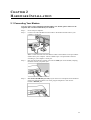
2.1 Connecting Your Modem
Note: For safety, before installing and uninstalling your modem, please make sure the
telephone line is UNPLUGGED from your modem.
Step 1:
Step 2:
Step 3:
Step 4:
Power off your computer.
Connect one end of the RS-232 serial cable to the modem and the other to your
computer’s serial port.
Note: Connect the male end of the RS-232 cable to the modem’s serial port and the
female end to your computer. Choose suitable 9-pin or 25-pin female connector
according to your computer’s serial port.
Plug one end of the RJ-11 phone cord into the LINE jack on the modem, and plug
the other end into your phone jack.
For model with PHONE port only. If you want to use a telephone on the modem’s
phone line while the modem is not used , plug the telephone’s cord into the
modem’s PHONE jack.
3
External Modem User's Manual
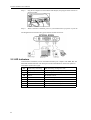
Step 5:
Plug the AC adapter into the modem’s AC IN jack, and plug the other end into an
electrical outlet.
Step 6:
When connection is finished, power on your modem before you power on your PC.
The diagram below illustrates the typical external modem connection:
2.2 LED Indicators
After hardware installation, turn on the modem and then your computer. The PWR, HS, and
MR LEDs should illuminate. The description of the LED indicators on the front panel are
listed below (from left to right) :
MR
Modem Ready/ Self-testing
HS
High Speed Speeds
On: Power on
Flash: Self-testing/ In diagnostic mode
On: Operating speed at 24000bps or higher
CD
Carrier Detect
On: Receiving a data carrier signal from remote modem
OH
Off Hook
SD
Send Data
RD
Receive Data
Flash: Receiving data to the modem
TR
Terminal Ready
On: Modem is on (unless setup by AT commands)
AA
Auto-answer
On: Set up to answer incoming calls
PWR Power
4
On: Modem off hook
Off: Modem on hook
Flash: Transferring data from the modem
On: power on
CHAPTER 3
DRIVER INSTALLATION
After hardware installation, turn on your modem and then power on your PC. Follow the
instructions below to install the drivers for the modem.
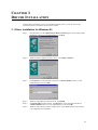
3.1 Driver Installation for Windows 95
Step 1:
Start Windows 95. The Update Device Driver Wizard appears. Insert the provided
Installation CD into your CD-ROM drive. Click Next.
Step 2:
Windows will be unable to locate a driver. Click Other Locations.
Step 3:
Click Browse to locate the path of the driver: x:\Driver\Win9x (where x is your
CD-ROM drive) and click OK.
Step 4:
Step 5:
Windows will find the location of driver; click Finish.
If Copying Files window appears, click Browse to locate the path of the driver:
x:\Driver\Win9x (where x is your CD-ROM drive) and click OK.
Windows will continue to detect another device. Click Next and then repeat steps 24 to complete driver installation.
Step 6:
5
External Modem User's Manual
When you are done with driver installation, you will need to specify the country where you
locate upon different telecommunication regulations/ laws. Please proceed to “3.6 Country
Selection” on page 15 for instructions.
6
Chapter 3 Driver Installation
3.2 Driver Installation for Windows 98
Step 1:
Start Windows 98. The Add New Hardware Wizard appears announcing the
detecting of a new hardware. Click Next. Insert the provided Installation CD into
your CD-ROM drive.
Step 2:
Select Search for the best driver for your device and click Next.
Step 3:
Check Specify a location. Click Browse to locate the path of the driver:
x:\Driver\Win9x (where x is your CD-ROM drive) and click OK. Click Next.
Step 4:
Step 5:
When Windows finds the driver file for the device, click Next.
If Copying Files window appears, click Browse to locate the driver file and click
OK.
Click Finish.
Step 6:
7
External Modem User's Manual
Step 7:
Windows will continue to detect another device. Click Next.
Step 8:
Step 9:
With Search for the best driver for your device checkbox selected, click Next.
Again, select Specify a location checkbox and the location should be:
x:\Driver\Win9x where x is your CD-ROM drive. Otherwise, repeat step 3 to
specify the location. Click Next.
Step 10: When Windows finds the driver file, click Next.
Step 11: If Insert Disk window appears, click Browse to locate the driver file and click OK.
Step 12: Click Finish to complete the installation.
When you are done with driver installation, you will need to specify the country where you
locate upon different telecommunication regulations/ laws. Please proceed to “3.6 Country
Selection” on page 15 for instructions.
8
Chapter 3 Driver Installation
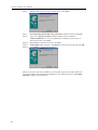
3.3 Driver Installation for Windows Me
Step 1:
Start Windows Me. The Add New Hardware Wizard appears. Insert the
Installation CD into your CD-ROM drive. Select Specify the location of the driver
(Advanced) and then click Next.
Step 2:
With Search for the best driver for your device selected, uncheck the Removable
Media checkbox and then check only the Specify a location checkbox. Click
Browse to locate the path of the driver: x:\Driver\WinME (where x is your CDROM drive) and click OK. Click Next.
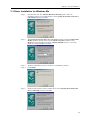
Step 3:
Step 4:
Windows will find the driver for the device. Click Next to continue.
Click Finish.
Step 5:
Windows will continue to detect another device. Select Specify the location of the
driver (Advanced) and then click Next.
9
External Modem User's Manual
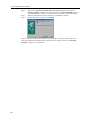
Step 6:
Step 7:
Step 8:
Again, select Search for the best driver for your device and check only the
Specify a location checkbox. The location should be: x:\Driver\WinME where x is
your CD-ROM drive. Otherwise, repeat step 2 to specify the location. Click Next.
Windows will find the driver for the device. Click Next to continue.
When installation is complete, click Finish.
When you are done with driver installation, you will need to specify the country where you
locate upon different telecommunication regulations/ laws. Please proceed to “3.6 Country
Selection” on page 15 for instructions.
10
Chapter 3 Driver Installation
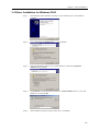
3.4 Driver Installation for Windows 2000
Step 1:
Start Windows 2000. Windows will detect a new hardware device, click Next to
continue.
Step 2:
Select Search for a suitable driver… and click Next.
Step 3:
Insert the Installation CD into your CD-ROM drive. Check ONLY Specify a
location and click Next.
Step 4:
Click Browse to locate the path of the driver: x:\Driver\W2K (where x is your CDROM drive) and click OK.
Step 5:
When Windows finds the location of the driver, click Next.
11
External Modem User's Manual
Step 6:
If Digital Signature Not Found window appears, click Yes to continue.
Step 7:
Click Finish. When Found New Hardware screen appears, wait for completing the
installation.
When you are done with driver installation, you will need to specify the country where you
locate upon different telecommunication regulations/laws. Please proceed to “3.6 Country
Selection” on page 15 for instructions.
12
Chapter 3 Driver Installation
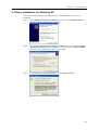
3.5 Driver Installation For Windows XP
Start Windows XP and insert the provided CD into your CD-ROM drive to start driver
installation.
Step 1
When Found New Hardware Wizard screen appears, select Install from a list or
specific location (Advanced) and click Next.
Step 2
With Search for the best driver in these locations selected, select ONLY Include
this location in the search. Click Browse to specify the path to X:\Driver\WinXP
where X is your CD-ROM drive letter and click Next.
Step 3
If compatibility prompt message appears, click Continue Anyway.
13
External Modem User's Manual
Step 4
Click Finish. When Found New Hardware screen appears, wait for completing the
installation.
When you are done with driver installation, you will need to specify the country where you
locate upon different telecommunication regulations/ laws. Please proceed to “3.6 Country
Selection” on page 15 for instructions.
14
Chapter 3 Driver Installation
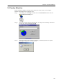
3.6 Country Selection
Before starting the modem, you may need to specify the country where you locate upon
different telecommunication regulations/ laws.
Step 1:
Click Start, point to Settings and then click on Control Panel. Double-click the
Modem Regional Settings icon.
Step 2:
The utility will start detecting automatically. You may click on the drop down arrow
to reset your country and then click OK.
Step 3:
Wait for resetting. When resetting is finished, the following window will appear.
Click OK to finish your country selection.
15
External Modem User's Manual
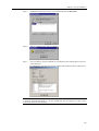
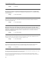
3.7 Verify that Your Modem is Properly Installed
3.7.1 For Windows 95/98/Me
Step 1:
Click Start, point to Settings and then click on Control Panel. Double-click the
Modems icon.
Note: If you are prompted with Location Information screen, enter your area code
and then exit the screen.
Step 2:
16
Highlight the IC+ 56k External Data Fax Voice Modem and then click on
Diagnostics tab.
Chapter 3 Driver Installation
Step 3:
Highlight the COM port used by your modem and click on More Info….
Step 4:
Wait for communication with your modem.
Step 5:
If your modem is properly installed, the command response should appear in the box
as the following.
Congratulations! You have successfully installed the modem hardware and its driver.
Note: If your modem fails to respond, you will see an error message. Make sure your modem
is properly installed and turned on. If your modem still fails to respond, you may need to
remove the driver and reinstall again.
17
External Modem User's Manual
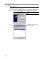
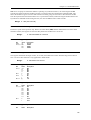
3.7.2 For Windows 2000/XP
Note: The configuration steps are the same in Windows 2000 and Windows XP. The graphics
here assume a Windows 2000 environment.
Step 1:
Click Start, point to Settings and then click on Control Panel. Double-click the
Phone and Modem Options icon.
Note: If Location Information is not provided yet, you will see the screen below.
Enter your location information and then click OK.
Step 2:
18
In Phone And Modem Options window, click on Modems tab. Highlight the IC+
56k External Data Fax Voice Modem and then click on Properties.
Chapter 3 Driver Installation
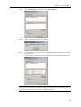
Step 3:
Click on Diagnostics tab and then click on Query Modem.
Step 4:
Wait for communication with your modem.
Step 5:
If your modem is properly installed, the command response should appear in the box
as the following.
Congratulations! You have successfully installed the modem hardware and its driver.
Note: If your modem fails to respond, you will see an error message. Make sure your modem
is properly connected. Switch your modem off and on, and try again. If your modem still fails
to respond, you may need to remove the driver and reinstall again.
19
CHAPTER 4
DRIVER UNINSTALLATION
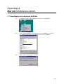
4.1 Uninstallation from Windows 95/98/Me
Step 1:
On the desktop, click on My Computer and right-click on Properties.
Step 2:
Click on Device Manager tab and then double-click the Modem icon. Highlight
IC+ 56k External Data Fax Voice Modem and then click on Remove .
Step 3:
When confirm message appears, click OK.
21
External Modem User's Manual
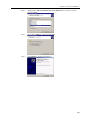
Step 4:
You will return to System Properties window and find that your modem is removed
from the hardware list.
4.2 Uninstallation from Windows 2000
Step 1:
22
Step 2:
Click Start, point to Settings and then click on Control Panel. Double-click the
Add/Remove Hardware icon.
Click Next.
Step 3:
Select the Uninstall/Unplug a device option and then click Next.
Step 4:
Select Uninstall a device and then click Next.
Chapter 4 Driver Uninstallation
Step 5:
Highlight IC+ 56k External Data Fax Voice Modem from your device list and
then click Next.
Step 6:
Select Yes, I want to… and then click Next.
Step 7:
Click Finish to complete uninstallation.
23
External Modem User's Manual
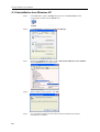
4.3 Uninstallation from Windows XP
24
Step 1
Click Start menu, point to Settings and then click on Control Panel. On the
Control Panel, double-click the System icon.
Step 2
Click Hardware tab and then click Device Manager.
Step 3
Double-click Modems and right-click IC+ 56k External Data Fax Voice Modem.
Select Uninstall from the context menu.
Step 4
When confirm message appears, click OK.
Step 5
You will find the modem has been removed from the hardware list and the
uninstallation is finished.
CHAPTER 5
COMMAND REFERENCE
This chapter includes all commands, S-Registers supported by the modem. Before using the
commands, make sure your communications software package provides the function of
operating the modem through its interna1 commands. If your software does not support the
function, ignore this chapter.
More than one command can be placed on a single line and, if desired, separated with spaces
for readability. Once the carriage return (Enter) key is pressed, the command line will be
executed. A line with no carriage return is ignored. If you come across terms that you don't
understand, consult the glossary. Words in boldface type are command names, commands, or
default settings. Carriage returns (Enter) are noted with <CR> or [ENTER]; this does not mean
to enter these characters literally; but instead to press the Enter key.
The modem accepts either upper or lower case characters in the command line and ignores any
space within or between commands. Typing errors can be corrected with the Backspace key.
Exceptions are noted in the description of specific commands.
Variables (r and x) are listed in italics. Punctuation symbols (, ; ! @) use as dial modifiers are
listed alphabetically according to their English names at the beginning of Section 5.2 where
two commands are separated by a slash, either command will have the same effect. For
example, if the command is listed as B0/B, issuing either B0 or B will have the same effect.
Note: Except for the A/ command and the + + + escape command described in Section 5.3, all
commands must be prefixed with the attention code AT. For instance, the A command (below)
would be entered as: "AT A <CR>". Without the AT prefix, the command line cannot be
executed. Once entered, AT cannot be deleted with the Backspace or Delete keys.
5.1 AT Commands
5.1.1 Basic Command Set
A
Go On-line in Answer Mode (For FAX Mode)
This command instructs the modem to go off-hook immediately and then make a handshake with the
remote modem. Handshaking is not available during leased line operation.
Bn
D
Select Protocol to ITU-V.22 or Bell 212A
B0/B
Selects ITU-V.22 protocol once the command line prefix AT has been entered at the 1200 bps
data rate.
B1
Selects BELL 212A protocol once the command line prefix AT has been entered at the 1200 bps
data rate. (Default)
Go On-line in Originate Mode
D instructs the modem to go off-hook immediately and automatically dial the number contained in the
dial string following D. The dial string may contain any of the dial modifiers contained in the following
section. The D command without a dial string is usually used to switch from voice conversation to data
communication or to call a remote modem in leased-line operation mode.
En
Command Echo
25
External Modem User's Manual
E0/E
Disables command echo.
E1
Enables command echo. (Default)
Hn
Hang Up
H0/H
Goes on-hook. (hangs up)
H1
Goes off-hook. (ready to dial)
In
Identification
I0/I
Report the product code.
I1
Report the hardware checksum.
I2
Report " TEST OK!".
I3
Report “TP560 Data/Fax/Voice 56K Modem).
I4
Report Firmware Version.
I5
Report the country.
I6
Report Local Phone Status.
Ln
Control Speaker Volume
L0/L
Low volume.
L1
Low volume.
L2
Medium volume. (Default)
L3
High volume.
Mn
Monitor Speaker On/Off
M0/M
Speaker is always off.
M1
Speaker is off while receiving carrier. (Default)
M2
Speaker is always on.
M3
Speaker disabled while dialing.
Nn
Automode Enable
N0/N
Automode detection is disabled.
N1
Automode detection is enabled.(Default)
On
26
Return to On-Line Data Mode
O0/O
Enters on-line data mode without a retrain. Handling is determined by the Call Establishment
task. Generally, if a connection exists, this command connects the DTE back to the remote
modem after an escape (+++).(Default)
O1
Enters on-line data mode with a retrain before returning to on-line data mode.
O2
Enters on-line data mode with a rate re-negotiation before returning to on-line data mode.
Chapter 5 Command Reference
P
Set Pulse Dial as Default
Causes the modem to assume that all subsequent dial commands are pulse dials. You may omit the "
P " from the dial strings.
Q
Result Code Display
Determines whether the modem sends the result codes to the DTE.
Q0/Q
Enables result codes to the DTE (Default).
Q1
Disables result codes to the DTE.
T
Set Tone Dial as Default
Causes the modem to assume that all subsequent dial commands are tone dial.
Vn
Select Word or Digit Result Codes
V0/V
Displays result codes in digital format.
V1
Displays result codes in verbose format. (Default)
W
Connect Message Control
This command controls the format of CONNECT messages.
W0/W
Upon connection, the modem reports only the DCE speed (e.g., CONNECT 19200).
Subsequent responses are disabled.
W1
Upon connection, the modem reports the line speed, the error correction protocol, and the DTE
speed, respectively. Subsequent responses are disabled.
W2
Upon connection, the modem reports the DCE speed (e.g., CONNECT 14400). Subsequent
responses are enabled.(Default)
W3
Upon connection, the modem reports the line speed, the error correction protocol, and the DTE
speed, respectively. Subsequent responses are enable.
Xn
Extended Result Codes
This command selects which subset of the result messages will be used by the modem to inform the
DTE of the results of commands.
Blind dialing is enabled or disabled by country parameters. If the user wishes to enforce dial tone
detection, a "W" can be placed in the dial string(see D command). Note that the information below is
based upon the default implementation of the X results table.
If the modem is in facsimile mode (+FCLASS=1) , the only message sent to indicate a connection is
CONNECT without a speed indication.
X0/X
CONNECT result code is given upon entering online data state. Dial tone and busy detection
are disable.
X1
CONNECT<text> result code is given upon entering online data state. Dial tone and busy
detection are disable.
X2
CONNECT<text> result code is given upon entering online data state. Dial tone detection is
enabled, and busy detection is disable.
X3
CONNECT<text> result code is given upon entering online data state. Dial tone detection is
disabled, and busy detection is enable.
27
External Modem User's Manual
X4
Z
CONNECT<text> result code is given upon entering online data state. Dial tone and busy
detection are enable.(Default)
Reset
Zn, which must be placed at the end of the command line, resets the active configuration of the modem to the
stored configuration saved in nonvolatile RAM, hangs up the modem, and clears the command buffer.
Z0/Z
Resets the modem and loads stored configuration 0.
Z1
Resets the modem and loads stored configuration 1.
5.1.2 Commands Preceded by &
&Cn
Select DCD Options
&C0/&C
Maintains an ON status for the Data Carrier Detect (DCD).
&C1
Uses the actual state of the carrier from the remote modem for DCD. (Default)
&Dn
Select DTR Options
Determines actions taken by the modem in relation to the Data Terminal Ready (DTR) signal of the serial port.
&D0/&D
DTR is ignored. Allows operation with DTEs that do not provide DTR.
&D1
DTR drop is interpreted by the modem as if the escape sequence has been entered. The
modem returns to the command state without disconnecting.
&D2
DTR drop causes the modem to hang up. Auto answer is inhibited. (Default)
&D3
DTR drop causes the modem to perform a soft reset as if the Z command were received.
&F
Fetch Factory Configuration
&F
&Gn
&Kn
Load Factory Setting.
Select Guard Tone
&G0/&G
Disable guard tone. (Default)
&G1
Select 550Hz-guard tone.
&G2
Select 1800Hz-guard tone.
DTE/Modem Flow Control
Determines how the modem controls the flow of data between the local DTE and the modem. When the modem
terminal buffer is nearly full, the modem will either send an XOFF or drop CTS to stop the data flow. When the
buffer is nearly empty, the modem will either send an XON or raise CTS to start the data flow.
&Pn
28
&K0/&K
Disable DTE/DCE flow control.
&K3
Enable RTS/CTS DTE/DCE flow control. (Default)
&K4
Enables XON/XOFF DTE/DCE flow control.
&K5
Enable RTS/CTS and transparent XON/XOFF DTE/DCE flow control.
Select Pulse Dial Make/Break Ratio
&P0/&P
Sets a 39/61 make/break ratio @ 10 pps. (Default)
&P1
Sets a 33/67 make/break ratio @ 10 pps.
Chapter 5 Command Reference
&Rn
&P2
Sets a 39/61 make/break ratio @ 20 pps.
&P3
Sets a 33/67 make/break ratio @ 20 pps.
CTR Signal Select
Determines whether CTR operates in accordance with the EIA-232-D specification or remains ON
&Sn
&R1/&R
CTR will become active when RTS is On.
&R0
CTS is always ON. (Default)
DSR Option
Determines whether DSR operates in accordance with the EIA-232-D specification or remains ON
&S0/&S
DSR is always ON. (Default)
&S1
DSR will become active after answer tone has been detected and inactive after the carrier
has been lost.
&Un
&V
Protocol Selection
&U0/&U
V.90 mode.(Default)
&U1
V.34 mode.
&U2
V.32bis/V.32/V.22bis mode.
View Configuration Profiles
&V
&W
&Yn
&Zn
Displays the active configuration profile.
Store the Current Configuration to Nonvolatile RAM
&W0/&W
Writes the current active configuration to profile 0 in nonvolatile RAM. (Default)
&W1
Writes the current active configuration to profile 1 in nonvolatile RAM.
Select the Default Profile
&Y0/&Y
Uses profile 0 on power-up. (Default)
&Y1
Uses profile 1 on power-up.
Store Telephone Numbers (n=0to2)
&Zn Store one of four dial strings (including a telephone number) of up to 31 digits in nonvolatile RAM.
For example: to store the telephone number 002852117 to RAM location 1, issue the following command:
Command:AT&Z1=002852117<CR>
5.1.3 Commands Preceded by *
*In
Connect Speed Selection
*I0
Selects connect speed 1200bps
*I1
Selects connect speed 2400bps
*I2
Selects connect speed 4800bps
*I3
selects connect speed 7200bps
*I4
Selects connect speed 9600bps
29
External Modem User's Manual
*I5
*I6
*I7
*I8
*I9
*I10
*I11
*I12
*I13
*I14
select V.90
*I1
*I2
*I3
*I4
*I5
*I6
*I7
*I8
*I9
*I10
*I11
*I12
*I13
*I14
*I15
*I16
*I17
*I18
*I19
*I20
*I21
*I22
*Gn
*Hn
Selects connect speed 12000bps
Selects connect speed 14400bps
Selects connect speed 16800bps
Selects connect speed 19200bps
Selects connect speed 21600bps
Selects connect speed 24000bps
Selects connect speed 26400bps
Selects connect speed 28800bps
Selects connect speed 31200bps
Selects connect speed 33600bps (Dafault)
Selects connect speed 28000bps
Selects connect speed 29333bps
selects connect speed 30666bps
Selects connect speed 32000bps
Selects connect speed 33333bps
Selects connect speed 34666bps
Selects connect speed 36000bps
Selects connect speed 37333bps
Selects connect speed 38666bps
Selects connect speed 40000bps
Selects connect speed 41333bps
Selects connect speed 42666bps
Selects connect speed 44000bps
Selects connect speed 45333bps
Selects connect speed 46666bps
Selects connect speed 48000bps
Selects connect speed 49333bps
Selects connect speed 50666bps
Selects connect speed 52000bps
Selects connect speed 53333bps
Selects connect speed 54666bps
Selects connect speed 56000bps (Dafault)
User Abort Selection
*G0/*G
Enables key abort feature.(Default)
*G1
Disables key abort feature.
Auto Retrain Selection
*H0/*H
Disables auto retrain
*H1
Enables auto retrain.(Dafault)
5.1.4 Commands Preceded by \
Operation Mode Control
\Nn
Selects the operating mode to be used during connection
\N0
30
Selects Normal (speed buffering) Mode.
Chapter 5 Command Reference
\N1
Selects Direct (pass-through) Mode.
\N2
\N3
Selects MNP or disconnect mode.
Selects MNP or Buffer.
\N4
Select V.42 without ODP&ADP phase detection, MNP or buffer.
\N5
Select V.42 with ODP&ADP phase detection, MNP or buffer.(Dafault)
\N6
Select V.42 without ODP&ADP or disconnect.
\N7
Select V.42 with ODP&ADP or disconnect.
\Vn
Single Line Connect Message Enable
The single line connect message format can be enabled or disabled by the \Vn command as follows:
\V0
Disable protocol result code appended to DCE speed. (Default)
\V1
Eisable protocol result code appended to DCE speed.
5.1.5 Commands Preceded by %
%C
Enable/Disable Data Compression
Enables or disable data compression negotiation. The modem can only perform data compression on an errorcorrected link.
%C0
Disables data compression.
%C1
Enables V.42bis/MNP 5.(Default)
5.2 Dial Modifiers
This section describes all of the dial modifiers that are used in dial strings.
@
Answer
"@", placed after a phone number, this modifier tells the modem to wait for 5 seconds of silence
before dialing the next number in the dial string. @ is usually used to access a secure computer
system that provides a silent answer as permission for further entrance.
,
Pause
",", placed anywhere in the dial string, tells the modem to pause for the number of seconds specified
by S-register S8 before processing the rest of the dial string.
!
Initiate a Hookflash
"!", placed anywhere in the dial string, tells the modem to initiate a hookflash, which means to hang up
for 0.5 seconds and then go off-hook again before processing the rest of the dial string. This modifier
allows access to PBX features like call transferring .
;
Return to Command State after Dialing
";", which must be placed at the end of the dial string, returns to the command state after dialing the
number placed ahead of it. A long telephone number would overflowthe 40 character command buffer
if placed all in one command line, so it must be broken into two or more command lines. Each part
31
External Modem User's Manual
includes part of the number, and all but the last command line end with the ";" followed by a carriage
return.
^
Tone Control
Toggles calling tone enable/disable:applicable to current dial attempt only.
P
Pulse Dialing
P, placed ahead of a number, tells the modem to dial a number using pulse dialing.
S
Dial a Stored Number
S is used to dial one of four numbers stored in nonvolatile memory. For example, instead of entering a dial string,
you can use this command:
Command: ATDS=1<CR>
T
Touchtone Dialing
T, placed ahead of a number, tells the modem to dial a number using touchtone dialing.
W
Wait for Dialtone
W, placed after a number, tells the modem to wait up to 30 seconds to detect a one-second
continuous dialtone before dialing the next number. W is most often used in a PBX system to wait for
the dialtone of an outside telephone line.
5.3 Commands Not Preceded By AT
Two commands, A/ and +++, are neither preceded by the attention code AT nor followed by a carriage
return.
A/
Repeat Command
A/ repeats the execution of the last command line stored in the command buffer. If the last command
line is invalid, the ERROR result code will appear on the screen. Note that A/ cannot be preceded by
AT; if it is, ERROR will appear on the screen.
+++
Escape
+++ followed by AT <CR> allows the modem to escape from the data mode to the on-line command state
(command state without breaking the established connection.)
To escape, stop transmitting data, wait at least one escape guard time (the default time is one second), and then
enter three consecutive escape characters (the default character is +) followed by AT <CR>.
The modem will return to the command state and send the OK result code to the screen. Note that the escape
command is the only command that can be recognized by the modem in the one-line state; it cannot be
recognized in the command state.
32
Chapter 5 Command Reference
5.4 S Register Reference
Your modem has status registers. These registers are memory locations inside your modem which control your
modem's operation. You usually do not have to worry about setting any register because the default values work
for most applications.
The S registers are summarized in 5.4.1, along with their default values. Registers denoted with an " * " may be
stored in one of the two user profiles by entering the &Wn command. One of these profiles may be loaded at
any time by using the Zn command.
The factory default values are stored in ROM and are loaded into the active configuration at power-up or by the
Zn command. In addition, the designated default profile is subsequently loaded, and may change some of the
factory default values. The designated default profile can be changed by entering the &Yn command, where 'n'
is one of the two possible user profiles. The factory defaults can be loaded at any time by entering the &F
command.
5.4.1 Register Summary
Important: The contents of the following registers are for reference.
The following chart summarizes your modem's registers:
Reg.# Range
Unit
S0
0 - 255
rings
S1
0 - 55
rings
S2
0 - 255
ASCII
S3
0 - 127
ASCII
S4
0 - 127
ASCII
S5
0 - 127
ASCII
S6
3-7
seconds
S7
1 - 255
seconds
S8
1 - 255
seconds
S9
1 - 255
1/10 sec.
S10 1 - 255
1/10 sec.
S11 50 - 255
1/1000 sec.
S12 0 - 255
1/50 sec.
S14 [Bit Mapped Options]
S21 [Bit Mapped Options]
S22 [Bit Mapped Options]
S23 [Bit Mapped Options]
S25 0 - 255
seconds
S26 0 - 255
1/100 sec
S29 [Bit Mapped Options]
S30 0 - 255
10 s
S95 [Bit Mapped Options]
S96 [Bit Mapped Options]
S97 [Bit Mapped Options]
S98 [Bit Mapped Options]
S99 0 - 255
Default
Dec
0
0
43
13
10
8
06h
60h
02h
6*
14*
95
50*
Hex
Description
00h
Number of rings before auto-answer.
00h
Ring count.
2Bh
Escape character code.
0Dh
Command terminator (<CR>character).
0Ah
Line feed character.
08h
Backspace character.
Wait time for blind dialing.
Wait time for carrier after dial.
Pause time for comma (dial delay).
06h
Carrier detect response time.
0Eh
Lost carrier to hang-up delay.
5Fh
DTMF Tone Duration.
32h
Escape code timing.
5*
1*
05h
01h
Dalay to DTR.
RTS to CTS Delay Interval.
0*
00h
Inactivity Disconnect Timer.
2
16
Energy detection threshold.
5.4.2 Glossary of the S Registers
S0
Number of Rings Before Auto Answer
S0 determines the number of rings that must be received before the modem automatically answers an
incoming call. For example, when S0=3, the modem automatically answers after the third ring. When
S0=0, the modem does not automatically answer an incoming call; it stays on-hook until the A
command is issued manually to answer the incoming call.
Range:
S1
0 - 255 rings
Ring Counter
S1 automatically increments its value by one each time the modem receives a ring while in the
command state. S1 is reset to zero if no ring is detected within 8 seconds.
33
External Modem User's Manual
Range:
S2
0 - 255 rings
Escape Character
S2 holds the decimal value of the ASCII character used as the escape character. The default value
corresponds to an ASCII '+'. A value over 127 disables the escape process, i.e., no escape character
will be recognized.
Range:
S3
0 - 255, ASCII decimal.
Line Termination Character
S3 sets the decimal value of the command line and result code terminator character. Pertains to
asynchronous operation only.
Range:
S4
0 - 127, ASCII decimal.
Response Formatting Character
S4 sets the decimal value of the character generated by the modem as part of the header, trailer, and
terminator for result codes and information text, along with the S3 parameter. If the value of S4 is
changed in a command line, the result codes issued in response to that command line will use the new
value of S4. The Response Formatting character is output after the Line Termination character if
verbose result codes are used.
Range:
S5
0 - 127, ASCII decimal.
ASCII Value of Backspace Character
S5 stores the ASCII value of the backspace character. The backspace is used to edit a command line. If your
computer does not recognize the default as a backspace, change the value.
Range:
S6
0 - 127, ASCII decimal.
Wait Time before Blind Dialing
S6 controls how long the modem waits after it goes off-hook before it dials the first digit of the telephone
number. The modem always pauses for at least 3 seconds, even if S6 is set to less than 3 seconds.
Range:
S7
3 - 7 seconds.
Wait for Carrier after Dial
S7 controls how long the modem waits for a carrier signal from a remote modem after originating a call or from
the calling modem after going off-hook when answering a call.
S7 also controls how long the modem waits for a one-second continuous dialtone after dialing a number
followed by the W dial modifier. If the modem detects a one-second continuous dialtone within the specified
wait time, it proceeds to dial.
34
Chapter 5 Command Reference
Range:
S8
1 - 255 seconds.
Pause Time for Comma
S8 controls how long the modem pauses when a comma ", " is encountered in a dial string while executing a
dial command.
Range:
S9
1 - 255 seconds.
Carrier Detect Response Time
S9 determines how long a carrier signal must be present for the modem to confirm it. The longer the response
time, the easier it is for the modem to correctly recognize a carrier without mistaking other signals or transient
noise on the line as a carrier.
Range:
S10
1 - 255 tenths of a second.
Lost Carrier To Hang Up Delay
S10 sets the length of time, in tenths of a second, that the modem waits before hanging up after a loss
of carrier. This allows for a temporary loss of carrier without causing the local modem to disconnect.
When S10 is set to 255, the modem functions as if a carrier is always present.
The actual interval the modem waits before disconnecting is the value in S10 minus the value in S9.
Therefore, the value in S10 must be greater than that in S9, or else the modem disconnects before it
recognizes the carrier.
Range:
S11
1 - 255 tenths of a second.
DTMF (Touch-tone) Tone Duration
S11 sets the duration of tone in DTMF dialing. This value has no effect on pulse dialing.
Range:
S12
50 - 255 milliseconds.
Escape Guard Time
S12 determines the escape guard time. The escape guard time is the minimum waiting time required before and
after entering the escape code (three consecutive escape characters) in the on-line state. It is also the maximum
waiting time allowed between any two consecutive escape characters. If the waiting time before or after the
escape code is shorter than the guard time, or if the waiting time between consecutive escape characters is longer
than the guard time, then the modem does not recognize the escape command and stays on-line.
If the escape guard time is set at 0 second, it is impossible to return the modem to command state.
Range:
S14
0 - 255 fiftieths of a second.
Bit Mapped Options
Bit
bit 0 (E)
bit 2 (Q)
Value
0
1
0
1
Description
Disabled.
Enabled.
Disabled.
Enabled.
35
External Modem User's Manual
bit 3 (V)
bit 4,5 (&P)
bit 6(P or T)
bit 7
S21
Numeric.
Verbose.
39/61 make to break ratio/10pps
33/67 make to break ratio/10pps
39/61 make to break ratio/20pps
33/67 make to break ratio/20pps
T (Tone dial).
P (Pulse dial).
Answer mode.
Originate mode.
Bit Mapped Options
Bit
bit 0
bit 2
bit 3,4
bit 5
bit 6
S22
0
1
00
01
10
11
0
1
0
1
Value
Description
[RESERVED]
0
&R0.
1
&R1.
00
&D0.
01
&D1.
10
&D2.
11
&D3.
0
&C0.
1
&C1.
0
&S0.
1
&S1.
Bit Mapped Options
Bit
bit 0,1
Value Description
00
Select L0.
01
Select L1.
10
Select L2.
11
Select L3.
bit 2,3
00
Select M0.
01
Select M1.
10
Select M2.
11
Select M3.
bit 4,5,6 000
Select X0.
001
Select X1.
010
Select X2.
011
Select X3.
100
Select X4
bit 7
[RESERVED]
S23
Bit Mapped Options
Bit
Value
Description
Bit 0,1,2,3
0000
0001
0010
0011
0100
0101
0110
0111
1000
1001
00
01
10
11
00
01
10
Communications rate = 300 bps.
Communications rate = 600 bps.
Communications rate = 1200 bps.
Communications rate = 2400 bps.
Communications rate = 4800 bps.
Communications rate = 9600 bps.
Communications rate = 19200 bps.
Communications rate = 38400 bps
Communications rate = 57600 bps
Communications rate = 115200 bps
Even parity.
None parity.
Odd parity.
Mark parity.
&G0.
&G1.
&G2
bit 4,5
bit 6,7
S25
36
Delay to DTR
Chapter 5 Command Reference
S25 serves two purposes. When the modem is operating in synchronous mode 1, the value assigned to S25
specifies the length of time the modem waits after a connection has been made before examining DTR. This
allows the modem to ignore an ON-to-OFF transition of DTR, giving the user time to disconnect the modem
from the asynchronous terminal and attach it to a synchronous terminal, without forcing the modem back to the
asynchronous command mode. During this time, the value for S25 is read in whole seconds.
Range: 0 - 255 (0.01 second)
S26
RTS to CTS Delay Interval
Pertains to synchronous operation only. When CTS tracks RTS (&R0) and the modem detects an ON-to-OFF
transition on RTS, this register sets the time delay before the modem turns CTS to ON.
Range:
S29
Bit Mapped Options
Bit
Value
bit0-4
(n)
bit 5,6,7 000
001
010
S30
0 - 255 hundredths of a second
Description
AT*I (n)
AT&U0
AT&U1
AT&U2
Inactivity Disconnect Timer
This register determines the length of time, in seconds, the modem waits before disconnecting when no data is
sent or received. This function is only applicable to buffer mode.
Range:
S95
Bit-Mapped Options
Bit
bit 0,1
Bit 2
Bit 3
Bit 4-7
S97
S98
0 - 255 tenths of a second
Value
00
01
10
11
0
1
0
1
(n)
Description
W0.
W1.
W2.
W3.
\V0.
\V1.
N0.
N1.
*On.
Bit-Mapped Options
Bit
Value
bit 0,1,2 000
001
010
011
010
011
110
111
Description
\N0.
\N1.
\N2.
\N3.
\N4.
\N5.
\N6.
\N7.
Bit 7
%C0.
%C1.
0
1
Bit-Mapped Options
Bit
Value
Description
37
External Modem User's Manual
bit 0,1
Bit 2
Bit 4-6
S99
00
01
0
1
000
011
101
110
*H0.
*H1.
*G0.
*G1.
&K0.
&K3.
&K4.
&K5.
Energy detection threshold
This register can use in Call Progress Mode (CPM) for dial tone detection threshold. The default value is 16 This
register determine the detection threshold for call progress tone.
38
CHAPTER 6
MODEM REFERENCE
6.1 Troubleshooting
This chapter describes common problems in the installation, configuration and regular usage of
your Fax/Data/TAM Modem. To test the Fax/Data/TAM Modem, a communication software
package is needed and the package must include a mode that allows you to operate your
Fax/Data/TAM Modem by directly issuing internal commands to the modem.
Follow the procedures in the following sections to resolve these common problems:
No Response From Your Modem
1. If you are using the internal add-on card modems, make sure that the COM port address
you have set your modem to corresponds to the appropriate selection in the
communications software which you are using.
2. Issue the ATZ command to reset your modem. The returned result code should be "0"
or "K" depending on what communications program you are using. Your modem is OK
if you get one of these responses. If there is no response after issuing the ATZ<CR>,
continue to the next step.
3. Check if there are any other interface cards in your computer that use the same COM
port address as your modem. If so, you must set your modem to another COM port
address.
4. Issue the command: AT&F&W <CR>, if a "0" or "K" result code is displayed on the
screen, your modem is OK. Otherwise, contact your dealer for assistance.
Your Modem Does Not Connect After It Has Dialed a Phone Number
The problem may have several causes. The phone line may be too noisy or the telephone cord
may be poor. Try the line with a regular phone. Also the remote modem may not recognize
your modem baud rate.
You Can Transmit After You Have Connected to the Remote Modem
In this case, check the communication parameters of the remote modem, then configure your
software to the same number of data bits, stop bit, and parity.
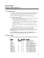
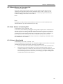
6.2 Result Codes
The modem sends a response to the user via the screen after a command is issued. As shown in
the figure below, there are two forms for each result code: Modem Response code and digit
code.
Response
OK
CONNECT
RING
NO CARRIER
ERROR
CONNECT 1200
NO DIALTONE
BUSY
NO ANSWER
CONNECT 300
CONNECT 2400
CONNECT 4800
CONNECT 9600
CONNECT 7200
CONNECT 12000
CONNECT 14400
CONNECT 19200
CONNECT 38400
CONNECT 57600
Digital
n value in ATXn
0 1 2 3 4
0
x x x x x
1
x x x x x
2
x x x x x
3
x x x x x
4
x x x x x
5
x x x x
6
x x
7
x x
8
x x
9
x x x x
10
x x x x
11
x x x x
12
x x x x
13
x x x x
14
x x x x
20
x x x x
21
x x x x
22
x x x x
23
x x x x
Description
Command executed without errors
Connect to another modem
Detect an incoming ring
Carrier lost or never detected
Invalid command or invalid character
Connection established at 1200 bps
Dial tone not detected within timeout
Detected a busy tone after dialing
No ringback or quiet answer was detected.
Connection established at 300 bps
Connection established at 2400 bps
Connection established at 4800 bps
Connection established at 9600 bps
Connection established at 7200 bps
Connection established at 1200 bps
Connection established at 14400 bps
Connection established at 19200 bps
Connection established at 38400 bps
Connection established at 56700 bps
39
External Modem User's Manual
CONNECT 115200
CONNECT 1200TX/75RX
1200 bps
CONNECT 75TX/1200RX
at 75 bps
CONNECT BELL 300
CONNECT V21
24
25
x x x x
x x x x
Connection established at 115200 bps
V.23 established:transmit at 75 bps, receive at
26
x x x x
V.23 established:transmit at 1200 bps, receive
28
29
x x x x
x x x x
Connection established at Bell 300 bps
Connection established at V.21 300 bps
( Display DCE speeds by ATW0 and ATW2 )
CONNECT 16800
CONNECT 19200
CONNECT 21600
CONNECT 24000
CONNECT 26400
CONNECT 28800
CONNECT 31200
CONNECT 33600
15
16
17
21
30
31
32
33
x
x
x
x
x
x
x
x
x
x
x
x
x
x
x
x
x
x
x
x
x
x
x
x
x
x
x
x
x
x
x
x
Connection established at 16800 bps
Connection established at 19200 bps
Connection established at 21600 bps
Connection established at 24000 bps
Connection established at 26400 bps
Connection established at 28800 bps
Connection established at 31200 bps
Connection established at 33600 bps
(V.90 mode)
CONNECT 28000
34
x x x x
Connection established at 28000 bps
CONNECT 29333
35
x x x x
Connection established at 29333 bps
CONNECT 30666
36
x x x x
Connection established at 30666 bps
CONNECT 32000
37
x x x x
Connection established at 32000 bps
CONNECT 33333
38
x x x x
Connection established at 33333 bps
CONNECT 34666
39
x x x x
Connection established at 34666 bps
CONNECT 36000
40
x x x x
Connection established at 36000 bps
CONNECT 37333
41
x x x x
Connection established at 37333 bps
CONNECT 38666
42
x x x x
Connection established at 38666 bps
CONNECT 40000
43
x x x x
Connection established at 40000 bps
CONNECT 41333
44
x x x x
Connection established at 41333 bps
CONNECT 42666
45
x x x x
Connection established at 42666 bps
CONNECT 44000
46
x x x x
Connection established at 44000 bps
CONNECT 45333
47
x x x x
Connection established at 45333 bps
CONNECT 46666
48
x x x x
Connection established at 46666 bps
CONNECT 48000
49
x x x x
Connection established at 48000 bps
CONNECT 49333
50
x x x x
Connection established at 49333 bps
CONNECT 50666
51
x x x x
Connection established at 50666 bps
CONNECT 52000
52
x x x x
Connection established at 52000 bps
CONNECT 53333
53
x x x x
Connection established at 53333 bps
CONNECT 54666
54
x x x x
Connection established at 54666 bps
CONNECT 56000
55
x x x x
Connection established at 56000 bps
6.3 Application Examples
6.3.1 Dialing a Remote Modem
Command line: ATDP9WT002, (886)-7128423<CR>
This command line instruct the modem to dial a remote modem through a PBX. The modem
first use pulse dialing to dial 9 (the access code of the PBX), wait for outside dial tone, and
then use touch tone dialing to dial 002 once a one-second continuous dial tone is detected
within 30 seconds, pause for 2 seconds (if S8=2) and then dial 8867128423.
6.3.2 Dialing a Stored Number
Command line: AT&Z2=T03,709394<CR>
Command line: ATDS=2<CR>
The first command line store the dial string T03, 709394 to the 3rd location in NVRAM.
Afterwards you can use the second command line to dial this stored number. The dial string
T03, 709394 will appear on the screen to indicate the number being dialed.
40
Chapter 6 Modem Reference
6.3.3 Manual Answer an Incoming Call
Command line: ATA <CR>
The factory setting of the S-register S0 is S0=0. This condition disables the auto answer
capability so that you must issue an ATA command to answer a call. At power up, your
modem always monitors if there are incoming rings. If incoming rings are detected, your
modem will display result codes on the screen as :
RING
:
:
RING
Seeing that, you may issue the ATA command to answer the call. This command must be
entered within the quiet interval between any two rings.
6.3.4 Auto Answer an Incoming Call
Command line: AT S0=2 &W &Y <CR>
Auto answer can be enabled by changing the setting of the S-register S0 to a value between 1
and 255. In the above command line, S0=2 instructs the modem to answer an incoming call
automatically after the 2nd ring. The &W command writes this configuration to profile 0 in
NVRAM. &Y command instruct the modem to load profile 0 as the active configuration on
power-up. The last two commands make S0=2 the default value at power-up or reset.
This example also shows the insertion of space between two neighboring commands to make
the command line more readable.
6.3.5 Voice to Data Switch
Command line: ATA <CR> or ATX1D <CR>
If you are talking with a remote modem user through the telephone set and want to initiate data
communication with the remote modem, follow the procedures below:
1.
2.
You or the remote user issue an ATA command first to switch to data communication.
When the person on the other end hears an answer tone from the phone, issues an
ATX1D command (X1 to disable the dial tone monitor) to instruct the modem to go offhook and wait for a carrier. If connection is successful, the CONNECT XXXX result
code will be displayed on the screen. Now you can hang up your phone and begin data
communication with the remote modem.
41
APPENDICES
Appendix A: Caller ID Commands (Optional)
+VCIDn - Caller ID (Enables or disables Caller ID.)
This command only apply to models which support the Caller ID function.
+VCID=0
Disables Caller ID.(Default.)
+VCID=1
Enables Caller ID with formatted presentation to the DTE. The modem will
present the data items in a <Tag><Value> pair format. The expected pairs are
data, time, caller code (telephone number), and name.
+VCID=2
Enables Caller ID with unformatted presentation to the DTE. The modem
will present the entire packet of information, excluding the leading U's, in
ASCII printable hex numbers.
Result Codes:
OK
n=0, 1 or 2.
ERROR Otherwise.
Inquiries :
+VCID?
Retrieves the current Caller ID mode from the modem.
+VCID=?
Returns the mode capabilities of the modem in a list with each element
separated by commas.
Formatted Form Reporting
The modem presents the data in the <tag>=<value> pair format as described in the table
below.Spaces are present on both sides of the equal sign.
TAG
DATE
Description
DATE=MMDD where MM is the month number(01 to 12) and DD is the day
number (01..31).
TIME=HHMM where HH is the hour number (00 to 23) and MM is the minute
number (00 to 59).
NMBR=<number> or P or O where <number> is the telephone number of the
caller, where P indicates that the calling number information is not available
since the originating caller as requested private service, and where O indicates
that the calling number information is not available or out of service at the
calling location.
NAME=<listing name> where <listing name> is the subscription name.
MESG=<data tag><length of message><data><checksum> in printable ASII
hex numbers. This tag indicates a data item not listed above. The message is
only possible for Multiple Message Format.
TIME
NMBR
NAME
MESG
Notes:
1.
The modem does not present any Caller ID information if the DCE detects a checksum
error in the Caller ID packet.
2.
In the event of an unrecognized data tag, the modem will present the data in ASCII hex
numbers following the MESG tag.
Example of Formatted Form Reporting
1.
The following example illustrates the standard Caller ID message packet.
RING
DATE = 0321
TIME = 1405
NMBR = 504551234
NAME = A N OTHER
RING
RING
2.
The following example illustrates the case where the tag of the packet is not recognized
by the modem.
RING
43
External Modem User's Manual
MESG = 06034242431
RING
RING
Unformatted Form Reporting
The modem presents all information and packet control information found in the message. The
modem, however, excludes the leading U's (channel seizure information) from the presentation.
The packet is presented in ASCII printable hex numbers, the modem does not insert spaces, or
line feeds, for formatting between bytes or words of the packet. The modem does not detect the
checksum of the packet.
Example of Unformatted From Reporting
RING
0412303332323234303539313435353132333435
RING
RING
44
Appendices
Appendix B: Technical Specifications
Data Rates(bps)
V.90:
Compatibility
(Data)
56000, 54667, 53333, 52000, 50667, 49333, 48000, 46667, 45333,
42667, 41333, 40000, 38667, 37333, 36000, 34667, 33333, 32000,
30667, 29333, 28000 (Receive only)
(Fax)
Command Set
ITU-T V.90, V.34, V.32 bis, V.32, V.22 bis and V.22
Bell: 212A
ITU-T V.17, V.29, V.27 ter, and V.21 ch 2
Enhanced 'AT' command set, Fax Class 1command
Flow Control
Xon/Xoff, Hardware RTS/CTS
Data Compression
V.42bis, MNP5
Error Correction
V.42, MNP 2-4
Operation
Maximum 56000 bps/download and 33600 bps/download with 28800,
26400, 24000, 21600, 19200, 14400, 9600, 4800, 2400 and 1200 bps
auto fallback
Audio Monitor
With software-controllable volume control
Guard Tone
550/1800 Hz
Command Buffer
30 characters
Extra Memory
4 x 36 digits
Transmit Level
-11(+/-2)dBm
Receive Sensitivity -32(+/-2)dBm
45
External Modem User's Manual
Appendix C: Quick Reference
A
Bn
D
En
Hn
In
Ln
Mn
Nn
On
P
Q
Sn
T
Vn
Wn
Xn
Zn
&Cn
&Dn
&F
&Gn
&Kn
&Pn
&Rn
&Sn
&Un
&V
&Wn
&Yn
&Zn
*In
*Gn
*Hn
\Nn
\Vn
%Cn
@
,
!
;
^
P
S
T
W
A/
+++
46
Go On-line in Answer Mode
Select Protocol to ITU-V.22 or Bell 212A
Go On-line in Originate Mode
Command Echo
Hang Up
Identification
Control Speaker Volume
Monitor Speaker On/Off
Automode Enable
Return to On-line Data Mode
Set Pulse Dial as Default
Result Code Display
Reading and Writing to S Registers
Set Tone Dial as Default
Select Word or Digit Result Codes
Current Message Control
Extended Result Codes
Reset
Select DCD Options
Select DTR Options
Fetch Factory Configuration
Select Guard Tone
DTE/Modem Flow Control
Select Pulse Dial Make/Break Ratio
CTS Signal Select
DSR Option
Protocol Selection
View Configuration Profiles
Store the Current Configuration to Nonvolatile RAM
Select the Default Profile
Store Telephone Numbers (n=0 to 2)
Connect Speed Selection
User Abort Selection
Auto Retrain Selection
Operation Mode Control
Single Line Connect Message Enable
Enable/Disable Data Compression
Answer
Pause
Initiate a Hookflash
Return to Command State after Dialing
Tone Control
Pulse Dialing
Dial a Stored Number
Touchtone Dialing
Wait for Dialtone
Repeat Command
Escape
Appendices
Appendix D: Glossary
ASCII
An acronym for American Standard Code for Information
Exchange. ASCII is a seven-bit code which defines 128 standard
characters, including control characters, letters, numbers, and
symbols. An extra 128 characters comprise the extended ASCII set.
Baud Rate
The transmission rate between two serial devices, e.g., modems,
fax machines, etc. Measured in Bits Per Second.
Blind Dialing
In blind dialing, the modem continues to dial, regardless of the
existence of a dialtone, ring, or busy signal.
BPS
Bits Per Second; the number of bits that can be transmitted in one
second.
Carrier Signal
The analog data signal that a modem sends over telephphone wires.
COMx
Where (x = 1, 2, 3, or 4), COMx is the name(address) of serial
communications ports on personal computers. Each serial port in a
personal computer has a different number.
CTS
Clear To Send.
Default
The assumed value that is used for a command parameter when no
other value is explicitly provided.
DCD
Data Carrier Detect.
DCE
Data Communication Equipment.
DTE
Data Terminal Equipment.
DTMF
Dual Tone Multi-Frequency (for touchtone dialing).
DTR
Data Terminal Ready.
FSK
Frequency Shift Keying.
Make/Break Ratio
The ratio of the off-hook (make) to on-hook (break) interval is the
make/break ratio in pulse dialing.
Modem
A combination of the words MOdulator and DEModulator.
Modems transform digital data into analog signals and back again.
Nonvolatile Memory
An area of memory inside the modem where the default
configuration profile is stored. Values recorded in this memory
will not be lost when the power is turned off.
Off-Hook
The condition when the modem has picked up the telephone line.
Off-Line Command State A modem state in which the modem accepts, interprets and
executes commands from an asynchronous computer or terminal.
On-Hook
The condition when the modem has not picked up the telephone
line; the telephone is hung up.
On-Line
A carrier signal link with a remote modem has been established;
communication is in progress.
On-Line State
A modem state in which the modem is connected with a remote
modem. Data can be sent or received from the remote modem in
this state. No commands will be accepted from the modem except
the escape command which will bring the modem into the on-line
command state.
On-Line Command State A modem state in which the modem can accept or execute
commands from an asynchronous computer or terminal while
remaining connected with the remote modem. The user can return
the modem to the on-line state by issuing the AT0n command or
put it into the off-line command state by issuing command such as
ATZ or ATH.
Parity
An error-checking method by which the modem verifies that the
data just sent is correct.
Pps
Pulse per second.
47
External Modem User's Manual
Profile
Protocol
PSK
Pulse Dialing
QAM
Result Codes
RAM
ROM
RTS
RX
S Register
Serial Port
TCM
Touchtone Dialing
TX
48
A list of default settings.
A technical specification for serial communications; the protocols
supported by the modem are listed in Appendix B.
Phase Shift Keying.
A dialing form in which each digit is represented by a series of
pulses. Rotary telephones all use pulse dialing.
Quadrature Amplitude Modulation.
The response the modem returns to the screen upon executing a
command.
Random Access Memory.
Read-Only Memory. A chip inside the modem which stores the
factory default settings. This memory cannot be changed.
Request To Send.
Reception.
RAM locations in the modem which store the active configuration.
See COMx.
Trellis-Coded Modulation.
A dialing format in which each digit is represented by a musical
frequency.
Transmission.
Appendices
Appendix E: ASCII CODE TABLE
Decimal
000
001
002
003
004
005
006
007
008
009
010
011
012
013
014
015
016
017
018
019
020
021
022
023
024
025
026
027
028
029
030
031
Hex Value Decimal Hex Value Decimal Hex
00 NUL 032
20 (space)064
01 SOH 033
21 !
065
02 STX 034
22 "
066
03 ETX 035
23 #
067
04 EOT 036
24 $
068
05 ENQ 037
25 %
069
06 ACK 038
26 &
070
07 BEL 039
27 '
071
08 BS
040
28 (
072
09 HT
041
29 )
073
0A LF
042
2A *
074
0B VT
043
2B +
075
0C FF
044
2C ,
076
0D CR
045
2D 077
0E SO
046
2E .
078
0F SI
047
2F /
079
10 DLE 048
30 0
080
11 DC1 049
31 1
081
12 DC2 050
32 2
082
13 DC3 051
33 3
083
14 DC4 052
34 4
084
15 NAK 053
35 5
085
16 SYN 054
36 6
086
17 ETB 055
37 7
087
18 CAN 056
38 8
088
19 EM
057
39 9
089
1A SUB 058
3A :
090
1B ESC 059
3B ;
091
1C FS
060
3C <
092
1D GS
061
3D =
093
1E RS
062
3E >
094
1F US
063
3F ?
095
Value Decimal
Hex Value
40 @
096
60
41 A
097
61
42 B
098
62
43 C
099
63
44 D
100
64
45 E
101
65
46 F
102
66
47 G
103
67
48 H
104
68
49 I
105
69
4A J
106
6A
4B K
107
6B
4C L
108
6C
4D M
109
6D
4E N
110
6E
4F O
111
6F
50 P
112
70
51 Q
113
71
52 R
114
72
53 S
115
73
54 T
116
74
55 U
117
75
56 V
118
76
57 W
119
77
58 X
120
78
59 Y
121
79
5A Z
122
7A
5B [
123
7B
5C \
124
7C
5D ]
125
7D
5E ^
126
7E
5F _
127
7F
'
a
b
c
d
e
f
g
h
i
j
k
l
m
n
o
p
q
r
s
t
u
v
w
x
y
z
{
|
}
~
■
49