1
AT&T
AT&T 555-620-110
Issue 1
October 1992
MERLIN LEGEND™
Communications System
Release 2.0
Feature Reference
Copyright © 1992 AT&T
All Rights Reserved
Printed in U.S.A.
AT&T 555-620-110
Issue 1
October 1992
Notice
Every effort was made to ensure that the information in this book was complete and accurate at the time of
printing. However, information is subject to change.
Federal Communications Commission (FCC)
Electromagnetic Interference Information
This equipment has been tested and found to comply with the limits for a Class A digital device, pursuant
to Part 15 of the FCC Rules. These limits are designed to provide reasonable protection against harmful
interference when the equipment is operated in a commercial environment. This equipment generates,
uses, and can radiate radio frequency energy and, if not installed and used in accordance with the
instruction manual, may cause harmful interference to radio communications. Operation of this equipment
in a residential area is likely to cause harmful interference, in which case the user will be required to correct
the interference at his own expense.
Canadian Department of Communications (DOC)
Interference Information
This digital apparatus does not exceed the Class A limits for radio noise emissions set out in the radio
interference regulations of the Canadian Department of Communications.
Le Présent Appareil Numérique n’émet pas de bruits radioélectriques dépassant les limites applicables
aux appareils numériques de la class A prescrites dans le Règlement sur le brouillage radioélectrique
édicté par le ministère des Communications du Canada.
Trademarks
5ESS, ACCUNET, CONVERSANT, Magic On Hold, MEGACOM, MERLIN, and MultiQuest are registered
trademarks, and 4ESS, AT&T FAX Attendant System, AUDIX Voice Power, InnManager, MERLIN Attendant,
MERLIN LEGEND, MERLIN MAIL, MLX-10, MLX-10D, MLX-20L, and MLX-28D are trademarks of AT&T in
the U.S. and other countries.
UNIX is a registered trademark of UNIX System Laboratories, Inc.
MS-DOS is a registered trademark of Microsoft Corp.
Support Telephone Number
AT&T provides a toll-free customer Helpline (1-800-628-2888) 24 hours a day (U.S.A. only). Call the
Helpline, or your authorized dealer, if you need assistance when installing, programming, or using the
system.
Contents
Customer Support Information
xiii
About this Book
xxv
xxvi
xxvii
xxviii
xxix
xxx
xxxii
■ Terms
and Conventions Used
■ Product Safety Labels
■ Security
■ How This Book Is Organized
■ Related Documents
■ How To Comment On This Document
Features
■ Index
of Feature Names
■ Abbreviated Ring
■ Account Code Entry/Forced Account Code Entry
■ Administration
■ Alarm
■ Allowed/Disallowed Lists
■ Auto Answer All
■ Auto Answer Intercom
■ Auto Dial
■ Automatic Line Selection and Ringing/Idle Line
Preference
■ Automatic Maintenance Busy
■ Automatic Route Selection
■ Barge-In
■ Call Waiting
■ Callback
■ Calling Restrictions
■ Camp-On
■ Centrex Operation
■ Conference
■ Coverage
■ Direct-Line Console
1
2
13
14
19
20
22
26
29
31
38
44
46
59
62
67
74
79
83
93
102
121
Table of Contents i
Contents
Features
(continued)
Station Selector MLX
■ Directories
■ Display
■ Do Not Disturb
■ Drop
■ Extension Status
■ Forced Account Code Entry
■ Forward and Follow Me
■ Group Calling
■ Headset Options
■ Hold
■ Idle Line Preference
■ Inside Dial Tone
■ Inspect
■ Integrated Administration
■ Labeling
■ Language Choice
■ Last Number Dial
■ Line Request
■ Messaging
■ Microphone Disable
■ Multi-Function Module
■ Music-on-Hold
■ Night Service
■ Notify
■ Paging
■ Park
■ Personal Lines
■ Personalized Ringing
■ Pickup
■ Pools
■ Power Failure Transfer
■ Primary Rate Interface (PRI)
■ Privacy
■ Programming
■ Direct
ii
Table of Contents
128
146
153
175
179
180
185
186
198
215
221
228
229
230
234
266
271
275
279
281
293
295
304
307
314
315
323
328
334
335
341
346
348
373
376
Contents
Features
(continued)
■ Queued Call Console
■ Recall/Timed Flash
■ Reminder Service
■ Remote Access
■ Ringing Line Preference
■ Ringing Options
■ Saved Number Dial
■ Signal/Notify
■ Speed Dial
■ Station Message Detail Recording (SMDR)
■ System Access/Intercom Buttons
■ System Renumbering
■ Timed Flash
■ Toll Type
■ Touch-Tone or Rotary Signaling
■ Transfer
■ Voice Announce to Busy
■ Volume
383
408
416
420
429
430
437
441
444
451
457
467
478
479
481
484
496
499
A
Features and Planning Forms
A-1
B
System Features
B-1
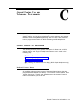
C
General Feature Use and Telephone
Programming
C-1
Table of Contents iii
Contents
D
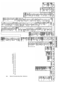
System Programming Menu Hierarchy
E
Sample Reports
E-1
F
Button Diagrams
F-1
G
Programming Special Characters
G-1
GL
Glossary
GL-1
IN
Index
iv
Table of Contents
D-1
IN-1
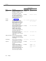
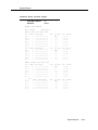
Figures
Features
Figure
Figure
Figure
Figure
Figure
1.
2.
3.
4.
5.
Figure 6.
Figure
Figure
Figure
Figure
Figure
Figure
7.
8.
9.
10.
11.
12.
Figure 13.
Figure 14.
Figure 15.
Figure 16.
Figure 17.
Figure 18.
Figure 19.
Figure 20.
Figure 21.
Figure
Figure
Figure
Figure
22.
23.
24.
25.
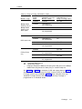
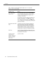
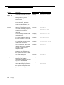
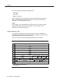
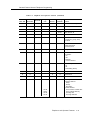
ARS Table Selection
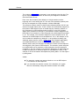
ARS Route Selection within a Table
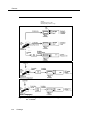
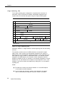
Full Centrex Service
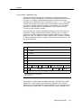
Limited Centrex Service
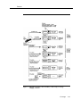
Group Coverage Only or All Individual
Coverage Receivers Not Available
Individual (Primary and Secondary) and
Group Coverage Ringing Patterns
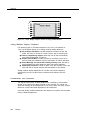
Direct Station Selector
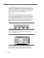
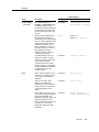
2-Line Display Home Screen
7-Line Display Home Screen
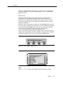
2-Line Display Menu Screen
7-Line Display Menu Screen
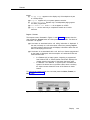
2-Line Display Inspect Screen for
Programmed Button
7-Line Display Inspect Screen for
Programmed Button
Application Switch Defaults Screens
Extension Directory Screen
AUDIX Voice Power and AUDIX Voice
Power/FAX Attendant User Screens
System Programming/Switch Admin Form
Screen
System Programming/Switch Admin Menu
Screen
Automated Attendant Screen
Automated Attendant Immediate Call
Handling Screen
Automated Attendant Delayed Call Handling
Screen
Automated Attendant Night Service Screen
Call Answer Screen
FAX Response Screen
Information Service Screen
54
55
85
86
112
113
129
156
156
157
157
159
160
242
245
247
250
254
255
256
257
258
259
260
261
Table of Contents v
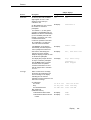
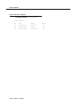
Figures
Features
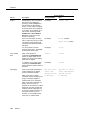
Figure 26.
Figure 27.
Figure 28.
Figure 29.
Figure 30.
Figure 31.
Figure 32.
Figure 33.
Figure 34.
Figure 35.
Figure 36.
F
262
263
360
378
379
380
389
452
470
472
473
Button Diagrams
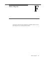
Figure F-1.
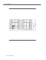
Figure F-2.
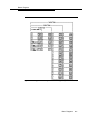
Figure F-3.
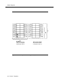
Figure F-4.
vi
(continued)
Message Drop Screen
Voice Mail Screen
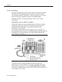
PRI Call Processing
MLX-20L Telephone
System Programming Console Overlay
SPM Display
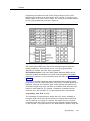
QCC Button Assignments
Sample SMDR Report in ISDN Format
2-Digit Numbering Plan
3-Digit Numbering Plan
Set Up Space Numbering Plan
Table of Contents
MLX Telephone Button Diagram (Hybrid/PBX
Mode)
Analog Multiline Telephone Button Diagram
(Hybrid/PBX Mode)
MLX Telephone Button Diagram (Key and
Behind Switch Mode)
Analog Multiline Telephone Button Diagram
(Key and Behind Switch Mode)
F-2
F-3
F-4
F-5
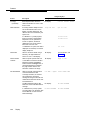
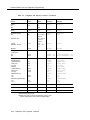
Tables
Features
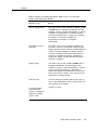
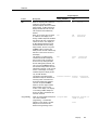
Table 1.
Table 2.
Table 3.
Table 4.
Table 5.
Table 6.
Table 7.
Table 8.
Table 9.
Table 10.
Table 11.
Table 12.
Table 13.
Table 14.
Table 15.
Table 16.
Table 17.
Table 18.
Table 19.
Table 20.
Special Characters for Auto Dial
Factory-Set Automatic Line Selection
Sequence
Timers Affecting Coverage
Ringing on Individual Coverage (Receiver)
Buttons
Calls Eligible and Calls Ineligible for
Coverage
Group Coverage Call Delivery Rules
Results of Pressing DSS Button While Active
on a Call: DLC Position with One-Touch Hold
Results of Pressing DSS Button While Active
on a Call: DLC Position with One-Touch
Transfer
Results of Pressing DSS Button While Active
on a Call: QCC Position
LED Meanings for Normal Call-Handling
Operation
LED Meanings for Supervisor Operation
without Message Status Active
LED Meanings for Hotel Extension Status
Operation without Message Status Active
LED Meanings for Normal Call Handling with
Message Status Active
LED Meanings for Supervisor or Hotel
Extension Status Operation with Message
Status Active
Call-Handling Displays
Feature Screen Options
Extension Status for Hotel Configuration
Extension Status for Calling Group/CMS
Configuration
Forwarded Call Ringing
Database Reconciliation Rules
33
40
105
106
108
111
132
133
134
135
137
138
140
140
154
158
181
182
189
237
Table of Contents
vii
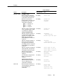
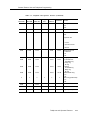
Tables
Features
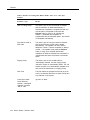
Table 21.
Table 22.
Table 23.
Table 24.
Table 25.
Table 26.
Table 27.
Table 28.
Table 29.
Table 30.
Table 31.
Table 32.
Table 33.
Table 34.
Table 35.
Table 36.
C
240
268
285
287
305
336
356
362
364
365
365
388
433
474
482
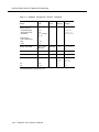
Telephone and Operator Features
Programming Analog Multiline Telephones
Programming MLX-10 Telephones
Programming MLX Display Telephones Using
the Display
C-4
C-17
C-18
C-19
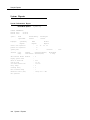
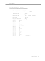
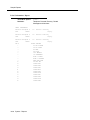
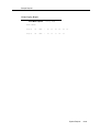
Sample Reports
Table E-1.
Table E-2.
viii
238
General Feature Use and Telephone
Programming
Table C-1.
Table C-2.
Table C-3.
Table C-4.
E
(continued)
Voice Channels Required
Screen-Labeled Function Keys for Integrated
Administration
Factory-Set Posted Messages and Their
Codes
Message Waiting Display Identifiers
Posted Messages
Music-on-Hold and Ringback
Types of Call Pickup
Line Compensation Settings
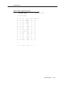
Sample Dial Plan Routing Table
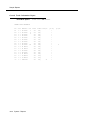
Sample Network Selection Table
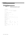
Sample Special Services Selection Table
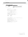
Sample Call-by-Call Services Table
Features Available at Call Progress Stages
Distinctive Ringing
Renumbering Extensions
Number of TTRs Required
Table of Contents
Report Contents
System Reports
E-1
E-3
Tables
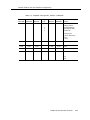
G
Programming Special Characters
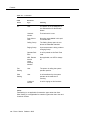
Table G-1.
Table G-2.
Table G-3.
Table G-4.
Special Characters for Single-Line
Telephones
Special Characters for Analog Multilane
Telephones
Special Characters for MLX Non-Display
Telephone
Special Characters for MLX Display
Telephones
G-1
G-2
G-3
G-4
Table of Contents
ix
Tables
x
Table of Contents
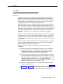
The exclamation point in an equilateral triangle is
intended to alert the user to the presence of
important operating and maintenance (servicing)
instructions in the literature accompanying the
product.
IMPORTANT SAFETY INSTRUCTIONS
When installing telephone equipment, always follow basic safety precautions to
reduce the risk of fire, electrical shock, and injury to persons, including:
■
Read and understand all instructions.
■
Follow all warnings and instructions marked on or packed with the
product.
■
Never install telephone wiring during a lightning storm.
■
Never install a telephone jack in a wet location unless the jack is
specifically designed for wet locations.
■
Never touch uninsulated telephone wires or terminals unless the
telephone wiring has been disconnected at the network interface.
■
Use caution when installing or modifying telephone lines.
■
Use only AT&T-manufactured MERLIN LEGEND™ Communications
System circuit modules, carrier assemblies, and power units in the
MERLIN LEGEND Communications System (511A) control unit.
■
Use only AT&T-recommended/approved MERLIN LEGEND
Communications System accessories.
■
If equipment connected to the analog station modules (008, 408,
408 GS/LS) or to the MLX telephone modules (008 MLX, 408 GS/LS-MLX)
is to be used for in-range out-of-building (IROB) applications, IROB
protectors are required.
■
Do not install this product near water, for example, in a wet basement
location.
■
Do not overload wall outlets, as this can result in the risk of fire or
electrical shock.
■
The MERLIN LEGEND Communications System is equipped with a
three-wire grounding-type plug with a third (grounding) pin. This plug
will fit only into a grounding-type power outlet. This is a safety feature. If
you are unable to insert the plug into the outlet, contact an electrician to
replace the obsolete outlet. Do not defeat the safety purpose of the
grounding plug.
■
The MERLIN LEGEND Communications System requires a
supplementary ground.
xi
■
Do not attach the power supply cord to building surfaces. Do not allow
anything to rest on the power cord. Do not locate this product where the
cord will be abused by persons walking on it.
■
Slots and openings in the module housings are provided for ventilation.
To protect this equipment from overheating, do not block these
openings.
■
Never push objects of any kind into this product through module
openings or expansion slots, as they may touch dangerous voltage
points or short out parts, which could result in a risk of fire or electrical
shock. Never spill liquid of any kind on this product.
■
Unplug the product from the wall outlet before cleaning. Use a damp
cloth for cleaning. Do not use cleaners or aerosol cleaners.
■
Auxiliary equipment includes answering machines, alerts, modems, and
fax machines. To connect one of these devices, you must first have a
Multi-Function Module (MFM).
WARNING:
For your personal safety, DO NOT install an MFM yourself.
ONLY an authorized technician or dealer representative shall
install, set options, or repair an MFM.
■ To eliminate the risk of personal injury due to electrical shock,
DO NOT attempt to install or remove an MFM from your MLX
telephone. Opening or removing the module cover of your
telephone may expose you to dangerous voltages.
■
■
SAVE THESE INSTRUCTIONS
xii
Customer Support Information
Support Telephone Number
In the U.S.A. only, AT&T provides a toll-free customer Helpline
(1-800-628-2888) 24 hours a day. Call the Helpline, or your authorized dealer, if
you need assistance when installing, programming, or using your system.
Outside the U.S.A., if you need assistance when installing, programming, or
using your system, contact your authorized AT&T dealer.
Federal Communications Commission (FCC) Electromagnetic Interference
Information
This equipment has been tested and found to comply with the limits for a
Class A digital device, pursuant to Part 15 of the FCC Rules. These limits are
designed to provide reasonable protection against harmful interference when
the equipment is operated in a commercial environment. This equipment
generates, uses, and can radiate radio frequency energy and, if not installed
and used in accordance with the instruction manual, may cause harmful
interference to radio communications. Operation of this equipment in a
residential area is likely to cause harmful interference, in which case the user
will be required to correct the interference at his own expense.
Canadian Department of Communications (DOC) Interference Information
This digital apparatus does not exceed the Class A limits for radio noise
emissions set out in the radio interference regulations of the Canadian
Department of Communications.
Le Présent Appareil Numérique n’émet pas de bruits radioelectriques
depassant les limites applicable aux appareils numériques de la class A
prescrites dans le reglement sur le brouillage radioelectrique edicté par le
ministère des Communications du Canada.
FCC Notification and Repair Information
This equipment is registered with the FCC in accordance with Part 68 of its
rules. In compliance with those rules, you are advised of the following:
Customer Support Information xiii
Customer Support Information
■
Means of Connection. Connection of this equipment to the telephone
network shall be through a standard network interface jack:
USOC RJ11C, RJ14C, RJ21X. Connection to E&M tie trunks requires a
USOC RJ2GX. Connection to off-premises stations requires a
USOC RJ11C or RJ14C. Connection to 1.544-Mbps digital facilities must
be through a USOC RJ48C or RJ48X. Connection to DID requires a
USOC RJ11C, RJ14C, or RJ21X. These USOCs must be ordered from
your telephone company.
This equipment may not be used with party lines or coin telephone lines.
■
Notification to the Telephone Companies. Before connecting this
equipment, you or your equipment supplier must notify your local
telephone company’s business office of the following:
—
—
—
—
—
—
The telephone number(s) you will be using with this equipment.
The appropriate registration number and ringer equivalence
number (REN), which can be found on the back or bottom of the
control unit, as follows:
If this equipment is to be used as Key System, report the
number AS593M-72914-KF-E.
If the system provides both manual and automatic selection
of incoming/outgoing access to the network, report the
number AS593M-72682-MF-E.
If there are no directly terminated trunks, or if the only
directly terminated facilities are personal lines, report the
number AS5USA-65646-PF-E.
The REN for all three systems is 1.5A.
For tie line connection, the facility interface code (FIC) is TL31M
and the service order code (SOC) is 9.0F.
For connection to off-premises stations, the FIC is OL13C and
the SOC is 9.0F.
For equipment to be connected to 1.544-Mbps digital service,
the FIC is 04DU9-B for D4 framing format or 04DU9-C for
extended framing format, and the SOC is 6.0P.
For equipment to be connected to DID facilities, the FIC is
02RV2-T and the SOC is 9.0F.
The quantities and USOC numbers of the jacks required.
For each jack, the sequence in which lines are to be connected:
the line types, the FIC, and the REN by position when applicable.
You must also notify your local telephone company if and when this
equipment is permanently disconnected from the line(s).
The REN is used to determine the number of devices that may be
connected to the telephone line. Excessive RENs on the line may result
in the devices not ringing in response to an incoming call. In most, but
not all, areas the sum of the RENs should not exceed five (5.0). To be
certain of the number of devices that may be connected to the line, as
determined by the total RENs, contact the telephone company to
determine the maximum REN for the calling area.
xiv
Customer Support Information
Customer Support Information
Installation and Operational Procedures
The manuals for your system contain information about installation and
operational procedures.
■
Repair Instructions. If you experience trouble because your equipment
is malfunctioning, the FCC requires that the equipment not be used and
that it be disconnected from the network until the problem has been
corrected. Repairs to this equipment can be made only by the
manufacturers, their authorized agents, or others who may be authorized
by the FCC. In the event repairs are needed on this equipment, contact
your authorized AT&T dealer or, in the U.S.A. only, contact the National
Service Assistance Center (NSAC) at 1-800-628-2888.
■
Rights of the Local Telephone Company. If this equipment causes
harm to the telephone network, the local telephone company may
discontinue your service temporarily. If possible, they will notify you in
advance. But if advance notice is not practical, you will be notified as
soon as possible. You will also be informed of your right to file a
complaint with the FCC.
Your local telephone company may make changes in its facilities,
equipment, operations, or procedures that affect the proper functioning
of this equipment. If they do, you will be notified in advance to give you
an opportunity to maintain uninterrupted telephone service.
■
Hearing Aid Compatibility. The custom telephone sets for this system
are compatible with inductively coupled hearing aids as prescribed by
the FCC.
■
Automatic Dialers. WHEN PROGRAMMING EMERGENCY NUMBERS
AND/OR MAKING TEST CALLS TO EMERGENCY NUMBERS:
— Remain on the line and briefly explain to the dispatcher the
reason for the call.
— Perform such activities in off-peak hours, such as early morning
or late evening.
■
Direct Inward Dialing (DID).
a.
This equipment returns answer supervision signals to the Public
Switched Telephone Network when:
(1)
answered by the called station
(2)
answered by the attendant
routed to a recorded announcement that can be
(3)
administered by the customer premises equipment user
(4)
routed to a dial prompt
b.
This equipment returns answer supervision on all DID calls
forwarded back to the Public Switched Telephone Network.
Permissible exceptions are when:
(1)
a call is unanswered
a busy tone is received
(2)
a reorder tone is received
(3)
Customer Support Information x v
Customer Support Information
Allowing this equipment to be operated in such a manner as not to
provide proper answer supervision signaling is in violation of
Part 68 rules.
DOC Notification and Repair Information
NOTICE: The Canadian Department of Communications (DOC) label identifies
certified equipment. This certification means that the equipment meets certain
telecommunications network protective, operational, and safety requirements.
The DOC does not guarantee the equipment will operate to the user’s
satisfaction.
Before installing this equipment, users should ensure that it is permissible to
connect it to the facilities of the local telecommunications company. The
equipment must also be installed using an acceptable method of connection.
In some cases, the company’s inside wiring for single-line individual service
may be extended by means of a certified connector assembly (telephone
extension cord). The customer should be aware that compliance with the above
conditions may not prevent degradation of service in some situations.
Repairs to certified equipment should be made by an authorized Canadian
maintenance facility designated by the supplier. Any repairs or alterations
made by the user to this equipment, or any equipment malfunctions, may give
the telecommunications company cause to request the user to disconnect the
equipment.
Users should ensure for their own protection that the electrical ground
connections of the power utility, telephone lines, and internal metallic water pipe
system, if present, are connected. This precaution may be particularly
important in rural areas.
CAUTION: Users should not attempt to make such connections themselves, but
should contact the appropriate electrical inspection authority or electrician, as
appropriate.
To prevent overloading, the Load Number (LN) assigned to each terminal
device denotes the percentage of the total load to be connected to a telephone
loop used by the device. The termination on a loop may consist of any
combination of devices subject only to the requirement that the total of the Load
Numbers of all the devices does not exceed 100.
DOC Certification No. 230 4095A
CSA Certification No. LR 56260
Load No. 6
Renseignements sur la notification du ministère des Communications du
Canada et la reparation
AVIS: L’étiquette du ministère des Communications du Canada identifie le
matériel homologué. Cette étiquette certifie que le matériel est conforme à
certaines normes de protection, d’exploitation et de sécurité des réseaux de
télécommunications. Le Ministère n’assure toutefois pas que le matériel
fonctionnera à la satisfaction de l’utilisateur.
Avant d’installer ce matériel, l’utilisateur doit s’assurer qu’il est permis de le
raccorder aux installations de l’entreprise locale de télécommunication. Le
xvi
Customer Support Information
Customer Support Information
matériel doit également être installé en suivant une méthode acceptée de
raccordement. Dans certains cas, les fils intérieurs de l’enterprise utilisés pour
un service individual à ligne unique peuvent être prolongés au moyen d’un
dispositif homologué de raccordement (cordon prolongateur téléphonique
interne). L’abonné ne doit pas oublier qu’il est possible que la conformité aux
conditions énoncées ci-dessus n’empêchent pas la dégradation du service
dans certaines situations. Actuellement, les entreprises de télécommunication
ne permettent pas que l’on raccorde leur matériel à des jacks d’abonné, sauf
dans les cas précis prévus pas les tarifs particuliers de ces entreprises.
Les reparations de materiel homologué doivent être effectuées par un centre
d’entretien canadien autorisé désigné par le fournisseur. La compagnie de
télécommunications peut demander à l’utilisateur de débrancher un appareil à
la suite de reparations ou de modifications effectuées par l’utilisateur ou à
cause de mauvais fonctionnement.
Pour sa propre protection, l’utilisateur doit s’assurer que tous les fils de mise à
la terre de la source d’énergie électrique, des lignes téléphoniques et des
canalisations d’eau métalliques, s’il y en a, sont raccordés ensemble. Cette
précaution est particulièrement importante dans les régions rurales.
AVERTISSEMENT: L’utilisateur ne doit pas tenter de faire ces raccordements
lui-même; il doit avoir recours à un service d’inspection des installations
électriques, ou à un electrician, selon le cas.
L’indice de charge (IC) assigné à chaque dispositif terminal indique, pour éviter
toute surcharge, le pourcentage de la charge totale qui peut être raccordée à
un circuit téléphonique bouclé utilisé par ce dispositif. La terminaison du circuit
bouclé peut être constitute de n’importe quelle combinaison de dispositifs,
pourvu que la somme des indices de charge de l’ensemble des dispositifs ne
dépasse pas 100.
No d’homologation: 230 4095A
No de certification: CSA LR 56260
L’indite de charge: 6
Customer Support Information
xvii
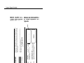
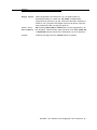
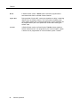
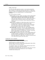
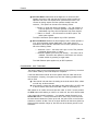
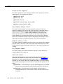
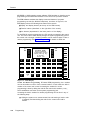
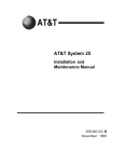
TELEPHONE
EQUIPMENT
Le présent appareil numérique n’émet pas de bruits
radioélectriques dépassant les limites applicables aux appareils
numériques de la classe A prescrites dans le Règlement sur le
radioélectrique édicté par le ministère des
brouillage
Communications du Canada.
This digital apparatus does not exceed the Class A limits for radio
noise emissions set out in the radio interference regulations of the
Canadian Department of Communications.
Complies with Part 68, FCC Rules. See the System Reference
Manual for proper FCC Classification.
FCC Reg. Nos. MF: AS593M-72682-MF-E
KF: AS593M-72914-KF-E
PF: AS5USA-65646-PF-E
REN: 1.5 A
This device compiles with Part 15 of the FCC Rules. Operation is
subject to the following two conditions: (1) this device may not
cause harmful interference, and (2) this device must accept any
interference received, including interference that may cause
undesired operation.
Si l’équipment est
utilisé pour des applications extérieures,
l’installation d’un protecteur secondair est
requise. Voir le manuel d’Installation.
AVERTISSEMENT:
If equipment IS used for
approved
applications,
out-of-building
See
secondary protectors are required.
Installation Manual.
WARNING:
® LR 56260
Use only AT&T manufactured MERLIN LEGEND circuit modules,
carrier assemblies, and power units, as specified in the installation
Manual, in this product. There are no user serviceable parts inside.
Contact your authorized agent for service and repair
MADE IN U.S.A
LISTED
538E
Model 511A Control Unit
MERLIN LEGEND
Customer Support Information
Security of Your System—Preventing Toll Fraud
As a customer of a new telephone system, you should be aware that there
exists an increasing problem of telephone toll fraud. Telephone toll fraud can
occur in many forms, despite the numerous efforts of telephone companies and
telephone equipment manufacturers to control it. Some individuals use
electronic devices to prevent or falsify records of these calls. Others charge
calls to someone else’s number by illegally using lost or stolen calling cards,
billing innocent parties, clipping on to someone else’s line, and breaking into
someone else’s telephone equipment physically or electronically. In certain
instances, unauthorized individuals make connections to the telephone network
through the use of remote access features.
The Remote Access feature of your system, if you choose to use it, permits offpremises callers to access the system from a remote telephone by using an 800
number or a 7- or 10-digit telephone number. The system returns an
acknowledgement signaling the user to key in his or her authorization code,
which is selected and administered by the system manager. After the
authorization code is accepted, the system returns dial tone to the user. If you
do not program specific egress restrictions, the user will be able to place any
call normally dialed from a telephone associated with the system. Such an offpremises network call is originated at, and will be billed from the system
location.
The Remote Access feature, as designed, helps the customer, through proper
administration, to minimize the ability of unauthorized persons to gain access to
the network. Most commonly, phone numbers and codes are compromised
when overheard in a public location, through theft of a wallet or purse
containing access information, or through carelessness (writing codes on a
piece of paper and improperly discarding it). Additionally, hackers may use a
computer to dial an access code and then publish the information to other
hackers. Enormous charges can be run up quickly. It is the customer’s
responsibility to take the appropriate steps to properly implement the features,
evaluate and administer the various restriction levels, protect access codes,
and distribute access codes only to individuals who have been fully advised of
the sensitive nature of the access information.
Common carriers are required by law to collect their tariffed charges. While
these charges are fraudulent charges made by persons with criminal intent,
applicable tariffs state that the customer of record is responsible for payment of
all long-distance or other network charges. AT&T cannot be responsible for
such charges and will not make any allowance or give any credit for charges
that result from unauthorized access,
To minimize the risk of unauthorized access to your communications system:
■
■
Use a nonpublished Remote Access number.
Assign authorization codes randomly to users on a need-to-have basis,
keeping a log of ALL authorized users and assigning one code to one
person.
Customer Support Information
xix
Customer Support Information
■
■
■
■
■
■
■
Use random sequence authorization codes, which are less likely to be
easily broken.
Deactivate all unassigned codes promptly.
Ensure that Remote Access users are aware of their responsibility to
keep the telephone number and any authorization codes secure.
When possible, restrict the off-network capability of off-premises callers,
via use of Call Restrictions and Disallowed List capabilities.
When possible, block out-of-hours calling.
Frequently monitor system call detail reports for quicker detection of any
unauthorized or abnormal calling patterns.
Limit Remote Call Forward to persons on a need-to-have basis.
Limited Warranty and Limitation of Liability
AT&T warrants to you, the customer, that your MERLIN LEGEND
Communications System will be in good working order on the date AT&T or its
authorized reseller delivers or installs the system, whichever is later (“Warranty
Date”). If you notify AT&T or its authorized reseller within one year of the
Warranty Date that your system is not in good working order, AT&T will without
charge to you repair or replace, at its option, the system components that are
not in good working order. Repair or replacement parts may be new or
refurbished and will be provided on an exchange basis. If AT&T determines
that your system cannot be repaired or replaced, AT&T will remove the system
and, at your option, refund the purchase price of your system, or apply the
purchase price towards the purchase of another AT&T system.
If you purchased your system directly from AT&T, AT&T will perform warranty
repair in accordance with the terms and conditions of the specific type of AT&T
maintenance coverage you selected. If you purchased your system from an
AT&T-authorized reseller, contact your reseller for the details of the
maintenance plan applicable to your system.
This AT&T limited warranty covers damage to the system caused by power
surges, including power surges due to lightning.
The following will not be deemed to impair the good working order of the
system, and AT&T will not be responsible under the limited warranty for
damages resulting from
■
■
■
■
■
failure to follow AT&T’s installation, operation, or maintenance
instructions
unauthorized system modification, movement, or alteration
unauthorized use of common carrier communication services accessed
through the system
abuse, misuse, or negligent acts or omissions of the customer and
persons under the customer’s control
acts of third parties and acts of God
AT&T’S OBLIGATION TO REPAIR, REPLACE, OR REFUND AS SET FORTH
ABOVE IS YOUR EXCLUSIVE REMEDY.
EXCEPT AS SPECIFICALLY SET FORTH ABOVE, AT&T, ITS AFFILIATES,
SUPPLIERS, AND AUTHORIZED RESELLERS MAKE NO WARRANTIES,
EXPRESS OR IMPLIED, AND SPECIFICALLY DISCLAIM ANY WARRANTIES OF
MERCHANTABILITY OR FITNESS FOR A PARTICULAR PURPOSE.
xx
Customer Support Information
Customer Support Information
Limitation of Liability
EXCEPT FOR PERSONAL INJURY, DIRECT DAMAGES TO TANGIBLE
PERSONAL PROPERTY PROXIMATELY CAUSED BY AT&T, AND LIABILITY
OTHERWISE EXPRESSLY ASSUMED IN A WRITTEN AGREEMENT SIGNED BY
AT&T, THE LIABILITY OF AT&T, ITS AFFILIATES, SUPPLIERS, AND
AUTHORIZED RESELLERS FOR ANY CLAIMS, LOSSES, DAMAGES, OR
EXPENSES FROM ANY CAUSE WHATSOEVER (INCLUDING ACTS OR
OMISSIONS OF THIRD PARTIES), REGARDLESS OF THE FORM OF ACTION,
WHETHER IN CONTRACT, TORT OR OTHERWISE, SHALL NOT EXCEED AN
AMOUNT EQUAL TO THE LESSER OF THE DIRECT DAMAGES PROVEN OR
THE PURCHASE PRICE OF THE SYSTEM. IN NO EVENT SHALL AT&T OR ITS
AFFILIATES, SUPPLIERS, OR AUTHORIZED RESELLERS BE LIABLE FOR
INCIDENTAL, RELIANCE, CONSEQUENTLY, OR ANY OTHER INDIRECT LOSS
OR DAMAGE (INCLUDING LOST PROFITS OR REVENUES) INCURRED IN
CONNECTION WITH THE SYSTEM. THIS LIMITATION OF LIABILITY SHALL
SURVIVE FAILURE OF THE EXCLUSIVE REMEDY SET FORTH IN THE LIMITED
WARRANTY ABOVE.
Voice Mail Systems
Your Voice Mail system permits callers to leave verbal messages for system
users or gain access to the back-up position in an emergency as well as create
and distribute voice messages among system users.
The Voice Mail system, through proper administration, can help you reduce the
risk of unauthorized persons gaining access to the network. However, phone
numbers and authorization codes can be compromised when overheard in a
public location, are lost through theft of a wallet or purse containing access
information, or through carelessness (writing codes on a piece of paper and
improperly discarding them). Additionally, hackers may use a computer to dial
an access code and then publish the information to other hackers. Substantial
charges can accumulate quickly. It is your responsibility to take appropriate
steps to implement the features properly, evaluate and administer the various
restriction levels, protect and carefully distribute access codes.
Under applicable tariffs, you will be responsible for payment of toll charges.
AT&T cannot be responsible for such charges and will not make any allowance
or give any credit resulting from unauthorized access.
To reduce the risk of unauthorized access through your Voice Mail system,
please observe the following procedures:
Employees who have voice mailboxes should be required to use the
passwords to protect their mailboxes.
— Have them use random sequence passwords.
— Impress upon them the importance of keeping their passwords a
secret.
— Encourage them to change their passwords regularly.
■ The administrator should remove any unneeded voice mailboxes from
the system immediately.
■
Customer Support Information
xxi
Customer Support Information
AUDIX Voice Power™ has the ability to limit transfers to subscribers only.
You are strongly urged to limit transfers in this manner.
■ Use the PBX or Key system administration capability to do the following:
— Block direct access to outgoing lines and force the use of
account codes/authorization codes.
— Disallow trunk-to-trunk transfer unless required.
— Assign toll restriction levels to all AUDIX Voice Power ports.
— If you do not need to use the Outcalling feature, completely
restrict the outward calling capability of the AUDIX Voice Power
ports.
■ Monitor SMDR reports or Call Accounting System reports for outgoing
calls that might be originated by AUDIX Voice Power ports.
■
Remote Administration and Maintenance
The Remote Administration and Maintenance feature of your
telecommunications system, if you choose to use it, permits users to change the
system features and capabilities from a remote location.
The Remote Administration and Maintenance feature, through proper
administration, can help you reduce the risk of unauthorized persons gaining
access to the network. However, telephone numbers and authorization codes
can be compromised when overheard in a public location, are lost through theft
of a wallet or purse containing access information, or through carelessness
(writing codes on a piece of paper and improperly discarding them).
Additionally, hackers may use a computer to dial an access code and then
publish the information to other hackers. Substantial charges can accumulate
quickly. It is your responsibility to take appropriate steps to implement the
features properly, evaluate and administer the various restriction levels, and
protect and carefully distribute access codes.
Under applicable tariffs, you will be responsible for payment of toll charges.
AT&T cannot be responsible for such charges and will not make any allowance
or give any credit resulting from unauthorized access.
To reduce the risk of unauthorized access through Remote Administration and
Maintenance, please observe the following procedures:
■
xxii
The System Administration and Maintenance capability of a PBX or Key
system is protected by a password.
— Change the default password immediately.
Continue to change the password regularly.
— Only give the password to people who need it and impress upon
them the need to keep it secret.
— If anyone who knows the password leaves the company, change
the password immediately.
Customer Support Information
Customer Support Information
■
If you have a special telephone line connected to your PBX or Key
system for Remote Administration and Maintenance, you should do one
of the following:
— Unplug the line when it is not being used.
— Install a switch in the line to turn it off when it is not being used.
— Keep the Remote Administration and Maintenance telephone
number secret. Only give it to people who need to know it, and
impress upon them the need to keep it a secret. Do not write the
telephone number on the PBX or Key system, the connecting
equipment, or anywhere else in the system room,
■
If your Remote Administration and Maintenance feature requires that
someone in your office transfer the caller to the Remote Administration
and Maintenance extension, you should impress upon your employees
the importance of only transferring authorized individuals to that
extension.
Customer Support Information xxiii
Customer Support Information
This page intentionally left blank.
xxiv
Customer Support Information
About This Book
The MERLIN LEGEND™ Communications System is an advanced digital
switching system that integrates voice and data communications features.
Voice features include traditional telephone features, such as Transfer and
Hold, and advanced features, such as Group Coverage and Park. Data
features allow both voice and data to be transmitted over the same system
wiring.
This book provides detailed information about system features and telephone
features, It is intended for use as a reference by anyone needing such
information, including support personnel, sales representatives, and account
executives. It is also intended for technicians who are responsible for system
installation, maintenance, and troubleshooting. Refer to the following
documentation for additional information:
■
Equipment and Operations Reference provides detailed information on
system hardware, telephones, and other equipment.
■
System Programming gives procedural instructions for programming
system features.
■
User’s Guides and Operator’s Guides give procedural instructions for
programming and using telephone features.
“Related Documents,” later in this section, provides a complete list of system
documentation together with ordering information.
In the U.S.A. only, AT&T provides a toll-free customer Helpline
(1-800-628-2888) 24 hours a day. Call the Helpline, or your authorized dealer,
if you need assistance when installing, programming, or using your system.
About This Book
xxv
About This Book
Terms and Conventions Used
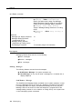
The following conventions are used in this book:
■
Bold type is used for imprinted (dedicated) or programmed telephone
buttons:
Two types of Auto Dial buttons can be programmed.
■
Italic type is used for emphasis and for information for which a specific
value will be substituted:
When calls are forwarded to an outside number, the feature is
called Remote Call Forward.
Dial ext. no., then dial feature code.
■
Constant width type is used for information that appears on a
telephone display screen, on a PC screen, in a report heading, or in the
system programming menu path that appears in the “At A Glance” box
that begins each feature:
Barge-In appears only on system operator consoles.
■
Bold constant width type is used for information that the user enters
exactly as shown:
If a user wishes to specify a different language, he or she can do
so using the -l option as follows:
spm -l english
spm -l french
spm -l spanish
■
Keys on the PC are shown in boxes.
Press [F7].
xxvi
Terms and Conventions Used
About This Book
Product Safety Labels
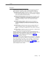
An exclamation point inside a triangle and the word “caution” or “Warning”
indicate hazardous situations. These product safety labels appear as follows:
WARNING:
Warning indicates the presence of a hazard that could cause death or
severe personal injury if the hazard is not avoided.
CAUTION:
Caution indicates the presence of a hazard that could cause minor
personal injury or property damage if the hazard is not avoided.
Product Safety Labels
xxvii
About This Book
Security
The use of passwords prevents unauthorized users from abusing the
communications system. It is strongly recommended that passwords be
assigned whenever possible and that the passwords are provided only to those
persons directly responsible for system administration and maintenance.
Non-displaying access codes and telephone numbers provide another layer of
security. The following cautionary note pertains to security:
CAUTION:
For more information about the security of your communications
system to prevent toll fraud, see the “Customer Support Information”
section at the front of this document.
xxviii
Security
About This Book
How This Book Is Organized
The description of each feature in this book is organized under the following
headings. Each heading is included as applicable for a given feature.
■
At a Glance provides a convenient table of feature-specific information
for quick reference. Information such as Users Affected, Reports
Affected, Mode, Telephones, Programming Code, Feature Code, MLX
Display Label, System Programming, Hardware, Maximums, and Factory
Settings is included as appropriate.
■
Description provides comprehensive information about the feature and
its use.
■
Considerations and Constraints lists exceptions and unusual
conditions pertaining to the feature.
■
Mode Differences explains variations in the use or operation of the
feature in Hybrid/PBX, Key, or Behind Switch mode.
■
Telephone Differences explains any operational variations on specific
telephones or consoles.
■
Feature Interactions describes how the feature operates when used in
conjunction with other features.
How This Book Is Organized
xxix
About This Book
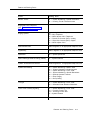
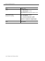
Related Documents
A number of related documents are available, providing additional information
about the communications system. (For ordering purposes, each title begins
with the product name: MERLIN LEGEND™ Communications System
Release 2.0.)
Within the continental United States, these documents can be ordered from the
AT&T Customer Information Center (CIC) by calling 1-800-432-6600 or by
contacting your local sales representative or authorized dealer.
Document No.
Title
555-620-114
555-620-110
555-620-115
555-620-116
555-620-111
555-620-112
555-620-113
System Documents
System Overview
Feature Reference
Equipment and Operations Reference
Pocket Reference
System Programming
System Planning
System Planning Forms
555-620-122
555-620-123
555-620-150
555-620-152
555-620-124
555-620-125
555-620-151
555-620-120
555-620-121
555-620-128
555-620-126
555-620-127
555-620-134
555-620-135
555-620-132
555-620-133
555-620-136
555-620-137
555-620-130
555-620-131
555-620-129
xxx
Related Documents
Telephone User Support
MLX-10D™, MLX-28D™, and MLX-20L™
Display Telephones User’s Guide
MLX-10D™, MLX-28D™, and MLX-20L™
Display Telephones Quick Reference
MLX-10D™ (Display) Telephone Tray Cards (6 cards)
MLX-28D™ and MLX-20L™ Telephone Tray Cards (5 cards)
MLX-10™ Non-Display Telephone User's Guide
MLX-10™ Non-Display Telephone Quick Reference
MLX-10™ (Non-Display) Telephone Tray Cards (6 cards)
Analog Multiline Telephones User’s Guide
Analog Multiline Telephones Quick Reference
MLC-5 Cordless Telephone Quick Reference
Single-Line Telephones User’s Guide
Single-Line Telephones Quick Reference
System Operator Support
MLX Direct-Line Consoles Operator’s Guide
MLX Direct-Line Consoles Quick Reference
Analog Direct-Line Consoles Operator's Guide
Analog Direct-Line Consoles Quick Reference
MLX Queued Call Console Operator’s Guide
MLX Queued Call Console Quick Reference
Miscellaneous User Support
Calling Group Supervisor’s Guide
Calling Group Supervisor’s Quick Reference
Data User’s Guide
About This Book
Document No.
555-620-140
555-620-141
555-620-142
555-620-143
555-620-144
Title
Documentation for Qualified Technicians
Installation, Programming, & Maintenance (lP&M) Binder
(consists of 555-620-141, 555-620-142, 555-620-143,
and 555-620-144)
Installation
System Programming & Maintenance (SPM)
Maintenance and Troubleshooting
Programming Summary
Related Documents
xxxi
About This Book
How to Comment on This Document
We welcome your comments about the usefulness of this document. Please tell
us what you like, as well as what you would improve. You may use the
feedback form on the next page to let us know how we can continue to serve
you. If the feedback form is missing, write directly to:
A. Sherwood
AT&T
99 Jefferson Road
Room 2A25
Parsippany, NJ 07054
xxxii
How to Comment on This Document
Features
This book is designed to provide both summary and detailed information about
every feature in the communications system. For each feature, the following
types of information are provided, as applicable:
■
At a Glance—summary information about the feature, including, for
example, users affected, telephones supported, programming code, and
factory settings
■
Description—a detailed description of the functions and typical uses of
the feature
■
Considerations and Constraints—an explanation of exceptions and
unusual conditions pertaining to the feature
■
Mode Differences—an explanation of variations in the use of the feature
in the different modes supported by the communications system
■
Telephone Differences—an explanation of variations in the use of the
feature with different telephones
■
Feature Interactions—a list of issues and considerations to be aware of
when using a feature in conjunction with another feature.
For ease of reference, features are covered in alphabetical order. For the
convenience of users of the previous releases of the communication system and
related products, an “Index of Feature Names” is included, showing where
information can now be found about features that may have been renamed or
reorganized in this release.
Features 1
Features
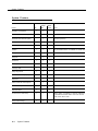
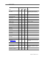
Index of Feature Names
Feature Name
See
400EM Module
7500B Module
*
*
A
Abbreviated Ring
Account Code Entry
Adapter
Adjuncts
Alarm
Alarm Clock
Allowed Lists
Applications
Area Code Tables
Asynchronous data management
Attendant Barge-In
Attendant DSS
Attendant Message Waiting
Attendant console - display
Attendant console — Switched Loop
AUDIX Voice Power
Auto Answer - All
Auto Answer - Intercom
Auto Dial
Auto Intercom
Auto Login/Logout (calling group)
Automated Attendant Service
Automated Document Delivery System (ADDS)
Automatic Answer (data management)
Automatic Callback
Automatic Completion
Automatic Extended Call Completion
Automatic Hold or Release
Automatic Line Selection
Automatic Maintenance Busy
Automatic Route Selection (ARS)
Autoqueuing
Auxiliary Power Units
*
2
Ringing Options
Account Code Entry/Forced Account Code Entry
*
Alarm, *
Display
Allowed/Disallowed Lists, Night Service
*
Automatic Route Selection
*
Barge-In
Direct Station Selector-MLX
Messaging
Display
Queued Call Console
Integrated Administration, *
Auto Answer All
Auto Answer Intercom
Auto Dial
Auto Answer Intercom
Group Calling
Integrated Administration, *
*
Auto Answer All, *
Callback, Remote Access
Transfer
Queued Call Console
Queued Call Console, Hold
Automatic Line Selection and
Ringing/Idle Line Preference
Automatic Maintenance Busy
Automatic Route Selection
Remote Access
*
See Equipment and Operation for further information.
Index of Feature Names
Features
Feature Name
See
B
Backup, battery
Barge-In
Barrier code
Behind Switch Mode
Behind Switch Operation
Billing number of caller
Bridging of station lines on multiline set
*
Barge-In
Remote Access
*
Recall/Timed Flash, Centrex Operation, *
Primary Rate Interface, Display
Personal Lines, System
Access/Intercom Buttons
C
Call
Call
Call
Call
Accounting Systems
Accounting Terminals
by Call Services Table
completion
Call Answer Service
Call Coverage
Call Forward(ing)/Following
Call Management System
Call Park
Call Pickup
Call Pickup-directed
Call Pickup-group
Call Records
Call Restrictions
Call Waiting
Callback
Callback Queuing
Calling Group
Calls-In-Queue Alarm
Camp On
Cancel Delivered Message
Capacities
CAS 100, 200
CAS Hospitality
CAS PIus
CAS UNIX
CAT — Business
CAT — Hospitality
Central Office (CO) Facilities
*
*
*
Primary Rate Interface
Transfer (One-Touch)
Queued Call Console (Extended)
Integrated Administration, *
Coverage
Forward and Follow Me
*
Park
Pickup
Pickup
Pickup
Station Messaging Detailed Recording (SMDR)
Calling Restrictions
Call Waiting
Callback
Callback
Group Calling, Integrated Administration
Group Calling, Queued Call Console (QCC)
Camp On
Messaging
*
*
*
*
*
*
*
*
See Equipment and Operation for further information.
Index of Feature Names 3
Features
Feature Name
See
Centralized Telephone Programming
Centrex
Class of Restriction
Channel Service Unit
Common Administration
Conference
Consultation Transfer
CONVERSANT ® Intro
Coverage Delay Interval
Coverage Group
Coverage Inhibit
Coverage On/Off
Coverage
Programming, †
Centrex Operation, *
Remote Access
*
Integrated Administration
Conference
Transfer
*
Coverage
Coverage, Integrated Administration
Coverage
Coverage
Coverage
D
Data Hunt Groups
Data Management
Data Privacy
Data Status
Data Support
Data transmission speed
Default Local and Toll tables
Delay Announcement
Delay Ring
Delete Message
Deliver Message
Dial by name (display feature)
Dial Dictation System Access (DDSA)
Dial Dictation adjunct
Dial Plan
Dial Plan Routing Table
Dial Tone
Dialed number
DID
Digital Data Ports
Digits in Extension
*
†
4
*
*
*
*
*
*
Automatic Route Selection
Group Calling
Ringing Options
Messaging
Messaging
Directories
*
*
System Renumbering
Primary Rate Interface
Inside Dial Tone
Display
*
*
System Renumbering
See Equipment and Operations Reference for further information.
See System Programming for further information.
Index of Feature Names
Features
*
†
Feature Name
See
Direct Dept. Calling (Hunting, Hunt Groups)
Direct Facility Termination (DFT)
Direct Group Calling (DGC)
Direct Inward Dialing (DID)Trunks
Direct Inward System Access (DISA)
Direct-line console
Direct Pool Termination (DPT)
Direct station selector
Directory built into PBX
Directory of System Speed Dial numbers
Directory of extension numbers
Disallowed Lists
Display
Display of name associated with station
Display prompting
Distinctive Ringing
Do Not Disturb
Drop
DSI facilities
Group Calling
Personal Lines
Group Calling
*
Remote Access
Direct-Line Console
Pools
Direct Station Selector-MXL
Directories
Speed Dial
Directories
Allowed/Disallowed Lists
Display
Labeling
Display
Ringing Options
Do Not Disturb
Conference
*
E
Electromagnetic interference (EMI) filter
Electrostatic discharge (ESD)
Environmental Requirements
Executive Barge-In
Extended call completion
Extended Station Status
Extension Auto Dial
Extension Directory
Extension Pickup
Extension programming
Extension Status
External Alerts
*
*
*
Barge-In
Queued Call Console
Extension Status
Auto Dial
Directories, Integrated Administration
Pickup
Programming, †
Extension Status, Group Calling
*
F
Facility alpha/number for incoming calls
Facility Restriction Level (FRL)
Fax Attendant
Fax message waiting
FCC Registration
Labeling
Automatic Route Selection
Integrated Administration
Messaging
*
See Equipment and Operation for further information.
See System Programming for further information.
Index of Feature Names 5
Features
Feature Name
See
Feature feedback
Flexible Numbering
Follow me
Forced Account Code Entry
Forward
Display
System Renumbering
Forward and Follow Me
Account Code Entry/Forced Account Code Entry
Forward and Follow Me
G
Group Coverage
Group Paging (Speakerphone)
Group Pickup
Pickup
*
*
*
Night Service
Pickup
Group Calling, Extension Status,
Integrated Administration
Coverage
Paging
Pickup
H
Hands Free Answer on Intercom (HFAI)
Hands Free Unit
Handset Mute
Headset Auto Answer
Headset Disconnect
Headset/Handset Mute
Headset Hang Up
Headset Operation
Headset Options
Headset Status
Headsets, hardware
Hold
Hold Reminder station
Hold Return
Hotel mode
Hunt Groups
Hunt type
Hybrid/PBX Mode
Auto Answer Intercom
Auto Answer Intercom
Headset Options
Headset Options
Headset Options
Headset Options
Headset Options
Headset Options
Headset Options
Headset Options, Queued Call Console
*
Hold
Display
Queued Call Console
Extension Status
Group Calling
Group Calling
*
General Pickup
General Purpose Adapter (GPA)
Ground Start Trunks
Grounding Requirements
Group Assignment
Group Call Pickup
Group Calling
*
6
See Equipment and Operation for further information.
Index of Feature Names
Features
Feature Name
See
I
ICOM buttons
Identification of stations being covered,
on covering party’s display
Idle Line Preference
Immediate ring
Individual Coverage
Individual Paging
Individual Pickup
Information Service
InnManager Guest Management System™
In-range Out-of-Building (IROB) protectors
Inside Auto Dial
Inside Dial Tone
Inspect
Inspect screen
Integrated Solution II/III
Intercom (ICOM) Buttons
Intercom dialing
Interfaces
IROB protectors
ISDN/PRI Interface
K
Key Mode
L
Labeling
Last Number Dial
Last Number Redial
Leave Message
Leave Word Calling
Line Pickup
Line request
Linesfirunks
Line/trunk pool button access
Line/trunk queuing
*
System Access/Intercom Buttons
Display
Automatic Line Selection and
Ringing/Idle Line Preference
Ringing Options
Coverage
Paging
Pickup
Integrated Administration
*
*
Auto Dial
Inside Dial Tone
Inspect
Display
*
System Access/intercom Buttons
System Access/Intercom Buttons
*
*
Primary Rate Interface (PRI), *
*
Labeling
Last Number Dial
Last Number Dial
Messaging
Messaging
Pickup
Line Request
*
Pools
Callback
See Equipment and Operations Reference for further information.
Index of Feature Names 7
Features
Feature Name
See
Loop Start Trunks
Loudspeaker paging
*
Paging, *
M
Maintenance Alarm
Maintenance Busy
Manual signaling
Menu-based feature activation
Menu-based station programming
MERLIN Attendant™
MERLIN ® II modules
MERLIN II System Display Console
MERLIN Mail™
Message (fax)
Message Center Operation
Message Drop Service
Message Indicator
Message Status (operator)
Message Waiting Receiver
Messaging
Microphone Disable
Missed Reminder
Mode Codes
Modem pooling, external
Modems
Modes of Operation
Multi-Function Module
Music-on-Hold
Mute
Mute, Headset/Handset
Alarm
Automatic Maintenance Busy
Signal/Notify
Display
Programming
*
*
Direct-Line Console
*
Messaging
Queued Call Console
Integrated Administration, *
Messaging
Messaging
Group Calling
Messaging
Microphone Disable
Reminder Service
*
*
*
*
Multi-Function Module, *
Music-on-Hold
Microphone Disable
Headset Options
N
N11 table
Name/number of internal caller
Network Central Office facilities
Network Interfaces
Next Message
Night Service
No Ring option
Notify
Numbering Plan
*
8
Automatic Route Selection
Display
*
*
Messaging
Night Service
Ringing options
Signal/Notify
System Renumbering
See Equipment and Operations Reference for further information.
Index of Feature Names
Features
Feature Name
See
O
Off-premises extensions
Off-premises Range Extender (OPRE)
On- or off-hook queuing
On-premises host access (data)
One-Touch Hold
One-Touch Transfer
Operator Automatic Hold
Operator Hold Timer
OPRE
Originate Only
Out-of-Building Station
Outside Auto Dial
Outward Restriction
*
*
Callback
*
Transfer
Transfer
Hold
Hold
*
System Access/Intercom Buttons
*
Auto Dial
Calling Restrictions, Night Service
P
Page All
Paging
Park
Patterns
PBX mode
Personal Directory
Personal Speed Dial
Personalized Ring
Pickup, Call Waiting
Pool Dial-Out Code Restriction
Pool routing
Pools
Port/Expansion carrier port slots
Position Busy Backup
Posted Messages
Power Failure Stations
Power Failure Transfer
Power Requirements
PRI
PRI Applications
Primary Coverage
Primary Rate Interface (PRI)
Prime Line
Principal/User
Printer
*
Paging
Paging
Park
Automatic Route Selection
*
Directories
Speed Dial
Ringing Options
Call Waiting
Calling Restrictions
Automatic Route Selection
Pools
*
Queued Call Console
Messaging
*
*
*
Primary Rate Interface
*
Coverage
Primary Rate Interface
Centrex Operation
Personal Lines, System Access/Intercom Buttons
Station Message Detail Recording (SMDR)
See Equipment and Operation for further information.
Index of Feature Names 9
Features
Feature Name
See
Printers, hardware
Priority call ringing
Privacy
Product Element Codes
Programming
*
Ringing Options
Privacy
*
Programming, Integrated Administration
Q
Queue Priority
Queued Call Console
Queued Call Console
Queued Call Console
R
Recall
Recorded Announcement
Release Differences
Reminder Service
Remote Access
Remote Administration
Remote Call Forwarding
Remote Programming
Restrictions
Retrieve Message
Return Call
Return Ring Interval
Ring Buttons
Ring Generator
Ring Timing Options
Ringback (Transfer Audible)
Ringing/Idle Line Preference
Ringing Options
Rotary Signaling
Routes per Pattern
Routing by Dial Plan
Recall/Timed Flash
*
*
Reminder Service
Remote Access
†
Forward and Follow Me
†
Calling Restrictions
Messaging
Messaging
Queued Call Console
System Access/Intercom Buttons
*
Ringing Options
Transfer
Automatic Line Selection and
Ringing/Idle Line Preference
Ringing Options
Touch-Tone or Rotary Signaling
Automatic Route Selection
Primary Rate Interface
S
SA buttons
Saved Number Dial
Scroll
Secondary Coverage
*
†
10
System Access/Intercom Buttons
Saved Number Dial
Messaging
Coverage
See Equipment and Operation for further information.
See System Programming for further information.
Index of Feature Names
Features
Feature Name
See
Selective Callback
Send All Calls
Send/Remove Message
Send Ring
Set Up Space
Shared System Access
Signaling
Simultaneous Conversations
Six-digit screening
SMDR
Software Capacities
Speakerphone paging
Special Numbers Pattern
Special Services Selection Table
Speed Dial
SPM
Station Conference - External Parties
Station Conference - Total Parties
Station DSS auto dial
Station lines
Station Message Detail Recording
Station programming
Station-to-Station Messaging
Supplemental Alert Adapter
Surge Protectors
Switched Loop Console
Switchhook (Flash)
Switching, Digital
System Access buttons
System Directory
System Numbering
System Programming
System Programming and Maintenance
System Speed Dial
Callback
Do Not Disturb
Messaging
Ringing Options
System Renumbering
System Access/Intercom Buttons
Signal/Notify
*
Automatic Route Selection
Station Message Detail Recording (SMDR)
*
Paging
Automatic Route Selection
Primary Rate Interface
Auto Dial, Directories, Speed Dial
Programming, †
Conference
Conference
Direct Station Selector
System Access/Intercom Buttons
Station Message Detail Recording (SMDR)
Programming
Messaging, Signal/Notify
Multi-Function Module, *
*
Queued Call Console
Recall/Timed Flash
*
System Access/Intercom Buttons
Directories
System Renumbering
Programming, †
Programming, †
Speed Dial
T
T1 Interface (DS1)
Telephones, hardware
Three-Digit Numbering
*
†
Primary Rate Interface, *
*
System Renumbering
See Equipment and Operation for further information.
See System Programming for further information.
Index of Feature Names 1 1
Features
Feature Name
See
Tie Trunks
Time day date (display)
Timed flash
Time of Day Routing
Tip/Ring devices
Toll Restriction
Toll Type
Touch-Tone Receivers
Touch-Tone Signaling
Transfer
Transfer Audible
Transfer Return Identification
Transfer Return Interval
T/R Devices
Trouble Alarm Connections
Trunk Pools
Trunk-to-Trunk transfer
TTRs
Two-Digit Numbering
*
Display
Recall/limed Flash
Automatic Route Selection
*
Calling Restrictions
Toll Type
Touch-Tone or Rotary Signaling, *
Touch-Tone or Rotary Signaling
Transfer
Transfer
Display
Transfer
*
*
Pools
Transfer
Touch-Tone or Rotary Signaling, *
System Renumbering
U
*
12
UDC/DDC
Unit Loads
Unrestricted Restriction
Group Calling
*
Calling Restrictions
V
Video Conferencing
VMI Ports
Voice announce
Voice announce disable
Voice announce inside calls
Voice announce on busy stations
Voice Announce Transfer
Voice Buttons
Voice mail message waiting
Voice mail systems
Voice Messaging Systems
*
Group Calling
Paging
Voice Announce to Busy
Paging, System Access/Intercom buttons
Voice Announce to Busy
Transfer
System Access/Intercom Buttons
Messaging
Integrated Administration, *
Integrated Administration, *
See Equipment and Operation for further information.
Index of Feature Names
Features
Abbreviated Ring
See Ringing Options.
Abbreviated Ring 1 3
Features
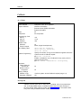
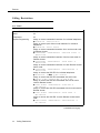
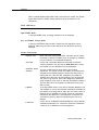
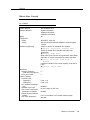
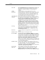
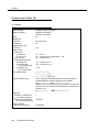
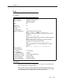
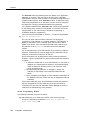
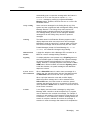
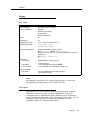
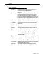
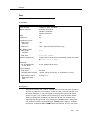
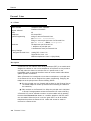
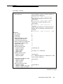
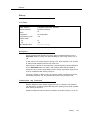
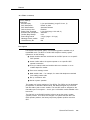
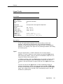
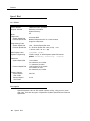
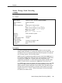
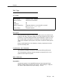
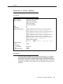
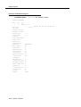
Account Code Entry/Forced Account
Code Entry
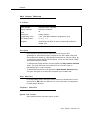
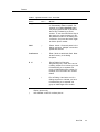
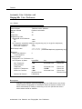
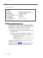
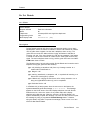
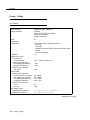
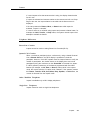
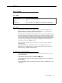
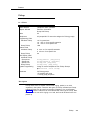
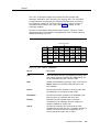
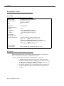
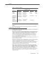
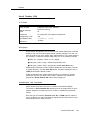
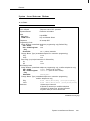
At a Glance
Users Affected
Reports Affected
Mode
Telephones
Programming Code
Feature Code
MLX Display Label
Telephone users, operators
Extension Directory
Extension Information
SMDR
All
All touch-tone telephones
*82
82
Account Code [Acct]
System Programming
Enter extensions required to use account codes before making
an outside call:
● Extensions → Account
Hardware
Printer for SMDR Reports or PC and printer equipped with AT&T
CAS software needed for Account Code Reports
Maximums
16 characters (0-9, *)
Factory Settings
Forced Account Code not assigned to any extensions
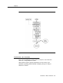
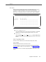
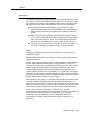
Description
Account Code Entry is used to enter account codes (developed by accounting
or administrative personnel) for outside calls, both incoming and outgoing.
These codes appear on Station Message Detailed Recording (SMDR) reports,
along with other call information, and are used for billing or cost accounting to
associate outgoing calls with a project, client, or department. Users can enter
an account code before or during a call, or not at all. They can also change,
correct, or cancel an account code while the call is in progress.
Forced Account Code Entry is similar, but affects only outgoing calls and
requires the user to enter an account code before placing an outside call.
Users can change or correct an account code while a call is in progress; they
cannot cancel it.
To enter, change, or correct an account code during a call, the user activates
the feature and enters the account code. The person who enters the account
code hears the tones generated by dialing the account code number. To
cancel an account code (when permitted), the user activates the feature and
exits without entering a code.
14
Account Code Entry/Forced Account Code Entry
Features
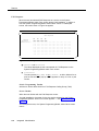
With Forced Account Code, a user who tries to make an outside call without
entering an account code experiences the following:
■
If a user selects an outside line on an SA button (by dialing a dial-out
code) or on an ICOM button (by dialing the Idle Line Access code)
without entering an account code, the call will be blocked. Depending on
the type of telephone used, this may be indicated by the Account Code
Entry button flashing, the SA button going to the off/idle state, or by
hearing an intercept tone.
■
If a user tries to make an outside call on a Personal Line or Pool button
without entering an account code, the caller does not receive dial tone.
Considerations and Constraints
An account code cannot be entered for incoming calls if SMDR is administered
to record outgoing calls only.
The system does not validate account codes; it only checks for the number of
characters entered (maximum of 16) and for completion (dialing # or pressing
an Account Code Entry display or feature button).
Account codes can be no more than 16 characters in length, and only the digits
0-9 and the character * can be used.
With Forced Account Code Entry, account codes can be entered for incoming
calls and for incoming calls added to a conference call by using the Account
Code Entry feature. The user does not have to enter account codes in these
situations. (Outgoing calls added to a conference must have an account code.)
A user cannot change an account code entered from another telephone.
An incoming caller cannot hear account codes entered during a call.
An Account Code Entry button only activates and completes the account code
entry. It does not automatically enter an account code. A separate outside Auto
Dial button can be programmed with the account code number.
Mode Differences
Behind Switch Mode
In Behind Switch mode, single-line sets must be programmed through Idle Line
Preference to select an SA or ICOM button when the user lifts the handset to
make an outgoing call.
Account Code Entry/Forced Account Code Entry 15
Features
Queued Call Consoles
To make an outgoing call activate Account Code Entry by selecting the feature
from the Home screen or by pressing the Feature button and selecting Account
Code Entry from the display After the account code is dialed, the entry is
completed by dialing #. Then select a Personal Line, SA, or Pool button on
which to make the call.
Normally account codes cannot be entered when a Group Coverage call is
answered at a Group Cover button programmed on a multiline telephone.
However, when the QCC queue is programmed as the receiver for a Coverage
group, Cover buttons are not required and the QCC system operator can enter
account codes. Those account codes appear on the SMDR printout. In this
case, the Account Code Entry feature must be activated from the display and
cannot be activated by dialing the feature code.
Other Multiline Telephones
An MLX telephone user can program account codes either individually, on
outside Auto Dial buttons, or as an entry in the Personal Directory (MLX-20L™
telephones). The user can enter an account code by pressing the Feature
button and selecting Account Code from the display.
On all other multiline telephones, Account Code Entry is activated by pressing a
programmed Account Code Entry button or by pressing the Feature button
and dialing 82. After the account code is dialed, the entry is completed by
pressing a programmed Account Code Entry button or dialing #. On MLX
display telephones, the feature can also be activated and completed by
pressing the Feature button and selecting the feature from the display. Once
the entry is completed, the user can select a Personal Line, SA, or Pool
button, lift the handset, and make the call.
NOTE:
If the multiline telephone user completes the entry by dialing a #, account
codes cannot be entered with System Speed Dial or Personal Speed Dial,
since the # is used to complete the entry and cannot also be used to
activate Speed Dial.
When Account Code Entry is assigned to a button, the LED flashes when the
user lifts the handset and attempts an outside call. On MLX display telephones,
the feature name appears on the display. The user can then enter the account
code, press the Account Code Entry button (the green LED goes from flashing
to on), select the outside line, and proceed with the call.
16
Account Code Entry/Forced Account Code Entry
Features
Single-Line Telephones
Single-line telephones in Behind Switch mode by default cannot use Account
Code Entry or Forced Account Code Entry. If this feature will be used, the
single-line telephone must be programmed through Idle Line Preference to
select an SA or ICOM button so that the user will hear internal dial tone when
the handset is lifted for an outgoing call.
Single-line telephones must have touch-tone dialing to use the Account Code
Entry feature.
When the single-line telephone has internal dial tone, the feature can be
activated by dialing #82.
Single-line telephone users cannot enter account codes with System Speed Dial
or Personal Speed Dial because these features are activated by dialing #. The
# completes the entry of an account code and cannot also be used to activate
the Speed Dial features.
Feature Interactions
Auto Dial
Frequently used account code numbers can be programmed
onto outside Auto Dial buttons.
Automatic Line
Selection
Account codes can be entered by a single-line telephone user
only when Automatic Line Selection is programmed to select an
SA or ICOM button when the user lifts the handset.
Automatic Route
Selection
When ARS is used on the system, an account code can be
entered before or after dialing the telephone number. If Forced
Account Code Entry is assigned, the user must enter the code
before dialing the ARS dial-out code.
Callback
An account code must be entered before the user activates
Callback. If not, the user must wait until after the call is
connected before entering the account code. Account codes
cannot be entered while the call is queued.
Conference
A separate account code must be entered for each outside call
added to a conference. An account code does not carry over to
other calls made at the same time.
Coverage
When answering calls on a Primary Cover, Secondary Cover,
or Group Cover button, a receiver cannot enter an account
code. The account code must be entered from the sender’s
telephone. (If the receiver tries to enter an account code, no
error tone sounds, but the account code does not appear on
the SMDR printout.) Since Cover buttons are not required when
the Queued Call Console (QCC) queue is programmed as a
receiver for a Coverage group, a QCC system operator can
enter account codes and have them appear on the SMDR
printout.
Account Code Entry/Forced Account Code Entry 17
Features
18
Display
When the Account Code Entry feature is activated, the Acct:
message on the display prompts the user to enter the account
code. The account code digits are shown next to the prompt as
they are dialed.
Forward and
Follow Me
Telephones with Forced Account Code Entry assigned can
forward calls only to extensions and not to outside numbers.
The user hears a fast busy signal if he or she tries to forward a
call to an outside number.
Remote Access
Account codes cannot be entered on calls made via Remote
Access.
Speed Dial
Multiline telephone users who use a programmed Account
Code button or display telephone users who select the feature
from the display can use Personal Speed Dial and System
Speed Dial to dial account codes. Single-line telephone users
and multiline telephone users who complete the entry by dialing
a pound sign (#) cannot use Personal Speed Dial or System
Speed Dial to dial account codes because # signals an exit
from the feature.
SMDR
The account code is printed in the ACCOUNT field of the SMDR
record. If the SMDR is administered for outgoing calls only, an
account code cannot be entered for an incoming call.
Transfer
When a call is transferred, the destination extension cannot
enter an account code to change the account code entered at
the originating telephone.
Account Code Entry/Forced Account Code Entry
Features
Administration
See Integrated Administration.
See Programming.
Administration 1 9
Features
Alarm
At a Glance
Users Affected
Reports Affected
Mode
Telephones
Operators
Extension Information
Programming Code
All
System operator consoles only (QCC or DLC)
*759
MLX Display Label
Alarm [Alarm]
System Programming
AuxEquip → MaintAlarms
Hardware
Alert device (bell or strobe) for Maintenance Alert
Description
Alarms provide either a visible or an audible indication when the system detects
a problem that needs immediate attention.
20
Alarm
■
Alarm button: A programmed button on Direct-Line Consoles (DLCS)
and Queued Call Consoles (QCCs) that alerts the system operator to
problems detected by the system software. The red LED next to the
Alarm button on the system operator console goes on when the system
detects a problem that requires immediate attention. It remains on until
the problem is corrected.
■
Maintenance Alert: An alert device such as a bell or strobe light
connected to the line or trunk designated as a Maintenance Alarm port.
The device rings or lights when the system detects a problem that
requires immediate attention.
■
The red LED on the processor module goes on when the system detects
a problem that requires immediate attention. It remains lit until the
problem is corrected.
■
The red LED on certain modules goes on when the system detects a
module-related problem, for example, a loss-of-service alarm on the
100D.
Features
Considerations and Constraints
The red LED next to the Alarm button goes on and/or the Maintenance Alert
sounds or flashes as soon as the system detects a problem.
All system operator consoles with an Alarm button receive the indication.
Telephone Differences
Direct-Line Consoles
Alarm buttons can be programmed only on system operator consoles; they
cannot be programmed on any other telephone.
An Alarm button is factory assigned as a fixed feature on an analog DLC, but
not on a digital DLC.
A digital DLC operator can use the Inspect feature to display the number of
alarms; an analog DLC operator cannot use Inspect.
Queued Call Consoles
Alarm buttons can be programmed only on system operator consoles; they
cannot be programmed on any other telephone.
An Alarm button is assigned as a fixed feature on a QCC.
A QCC operator can use the Inspect feature to display the number of alarms.
Feature Interactions
Automatic
Maintenance Busy
The red LED goes on next to the Alarm button on system
operator consoles, and the designated Maintenance Alert
device sounds or flashes when more than 50 percent of the
trunks in the trunk pool are in a maintenance-busy state.
Inspect
Inspect can be used on a digital DLC or a QCC to display the
number of alarms. Inspect cannot be used on an analog DLC.
Personal Lines
A line or trunk jack used for a Maintenance Alarm cannot be
assigned as a Personal Line.
Pools
A trunk jack used for a Maintenance Alarm cannot be assigned
to a trunk pool (Hybrid/PBX only).
Alarm
21
Features
Allowed/Disallowed Lists
At a Glance
Users Affected
Reports Affected
Mode
Telephones
System Programming
Maximums
Allowed Lists
Disallowed Lists
22
Telephone users, operators
Access to Allowed Lists
Access to Disallowed Lists
Allowed Lists
Disallowed Lists
Remote Access (DISA) Information
All
All
Establish, change, or remove Allowed/Disallowed Lists:
● Tables → AllowList/Disallow
Assign or remove Allowed/Disallowed Lists for individual
telephones:
● Tables → AllowTo/DisallowTo
Assign or remove Allowed/Disallowed Lists for non-tie trunks
used for Remote Access:
● Lines Trunks → RemoteAccss → Non-TIE Lines →
Allow List/DisallowLst
Assign or remove Allowed/Disallowed Lists for tie trunks used
for Remote Access:
● Lines Trunks → RemoteAccss → TIE Lines →
Allow List/DisallowLst
Assign or remove Allowed/Disallowed Lists for each Remote
Access barrier code:
● Lines Trunks → RemoteAccss → Barrier Code →
Allow List/DisallowLst
6 digits per number (+ leading 1, if required)
10 numbers per list
8 lists per system
8 lists per telephone
11 digits per number (+ wildcard)
10 numbers per list
8 lists per system
8 lists per telephone
Allowed/Disallowed Lists
Features
Description
Used in conjunction with Calling Restrictions (outward and toll), an Allowed List
is a list of numbers that the user is allowed to dial, despite restrictions. For
example, an Allowed List assigned to an outward-restricted telephone can allow
calls to specific local numbers, such as emergency (911), or toll numbers. For
toll-restricted telephones, an assigned Allowed List can allow calls to specific
area codes and/or exchanges needed for daily tasks.
A Disallowed List is a list of local or toll numbers that the telephone user is not
allowed to dial, even if the telephone is otherwise unrestricted. Disallowed Lists
can be used as an alternative to or in conjunction with Calling Restrictions.
Both Allowed Lists and Disallowed Lists are assigned to individual extensions.
Allowed and Disallowed Lists can also be used in conjunction with Remote
Access to restrict calls made through the system from remote locations, In this
case, Allowed and Disallowed Lists can be assigned to either specific Remote
Access barrier codes or (if barrier codes are not used) to specific types of
trunks--all Tie/DID and all non-Tie/non-DID trunks.
When an Allowed List is assigned to a barrier code or remote access trunks, the
remote access user using that code can dial specific numbers included in the
list. When a Disallowed List is assigned to a barrier code, the remote access
user using that code cannot reach the specific numbers included in the list.
If barrier codes are not used for remote access, then Allowed and Disallowed
Lists for remote access users can be assigned to all Tie/DID trunks, and all
non-Tie, non-DID trunks.
A Night Service Allowed List can be programmed with up to ten numbers that
any user can dial without having to enter the Night Service password. For
additional information, see Night Service.
Considerations and Constraints
A Disallowed List takes precedence over an Allowed List. If a telephone
number is on both an Allowed List and a Disallowed List assigned to an
individual extension, the user cannot dial the number.
If a zero (0) is programmed as the first digit of an Allowed List entry, any toll
restriction assigned to a telephone is removed for calls placed through a toll
operator.
Individual Allowed and Disallowed Lists are numbered 0 through 7. Within each
list, entries are numbered 0 through 9.
The Pause character (entered by pressing Hold) can be used as a wild card
character in Disallowed Lists, for example, to indicate that calls to a given
exchange are restricted in every area code. (The Pause character is shown on
the planning form as p.) Wild card characters are not permitted in Allowed List
entries.
Allowed/Disallowed Lists 2 3
Features
When used in conjunction with Remote Access, Allowed and Disallowed Lists
are assigned to specific barrier codes or to types of trunks--all Tie/DID trunks, or
all non-Tie DID trunks. Allowed and Disallowed Lists cannot be assigned to
trunks on an individual basis.
When used with Automatic Routing System (ARS), Allowed and Disallowed Lists
are not applied until the user dials the ARS code and a pool is selected.
Because restrictions imposed by a Disallowed List apply to the telephone used
to initiate a call to an outside number, a user with a restricted telephone can
circumvent restrictions by asking a system operator with an unrestricted
console to connect an outside call.
Feature Interactions
Auto Dial
A user with a restricted telephone cannot dial a restricted
number (outside or toll) by using an Auto Dial button unless the
number is on the Allowed List for that telephone. A user cannot
dial an outside number by using an Auto Dial button if the
number is on a Disallowed List.
Automatic Route
Selection
Automatic Route Selection (ARS) checks Allowed and
Disallowed Lists before choosing the route for a call. This
prevents users with restricted telephones from dialing numbers
that are not on an Allowed List. ARS also prevents a user from
dialing numbers on a Disallowed List.
Calling
Restrictions
When used with Calling Restrictions, Allowed Lists can permit
the dialing of specific numbers such as emergency numbers
from an outward-or toll-restricted telephone.
Conference
A user with a restricted telephone cannot add a participant
(outside or toll) to a conference call unless the participant’s
number is on the Allowed List for that telephone.
A user cannot add an outside number to a conference call if the
number is on a Disallowed List.
24
Directories
A user with a restricted telephone cannot use the System
Directory to dial a restricted number unless the System Speed
Dial number is marked or the number is on the Allowed List for
that telephone.
Forward and
Follow Me
A user with a restricted telephone cannot forward calls to a
restricted (outside or toll) number unless the number is on the
Allowed List for that telephone. If the number is on the
Disallowed List for that telephone, the call cannot be forwarded.
When activating Forward, a user with a restricted telephone
does not hear an error tone, but when a call is received, the
Forward is denied if the number is not on the Allowed List.
Allowed/Disallowed Lists
Features
Night Service
A Night Service Emergency Allowed List can be programmed
with up to ten numbers that any user can dial without having to
enter the Night Service password. For additional information,
see Night Service.
Personal Lines
A user with a restricted telephone cannot dial a restricted
number (outside or toll) on a Personal Line button unless the
number is on the Allowed List for that telephone. If the number
is on a Disallowed List, the user cannot dial it.
Remote Access
Both Allowed and Disallowed Lists are assigned as items of the
class of restriction (COR) for the Remote Access feature. When
barrier codes are not used, Allowed and Disallowed Lists are
assigned to trunks system-wide. When barrier codes are used,
Allowed and Disallowed Lists are assigned to individual barrier
codes.
Speed Dial
When a marked System Speed Dial number (the dialed number
is suppressed from the display) is used to dial a number, calling
restrictions (such as toll or outward restrictions) assigned to that
telephone are overriden. When an unmarked System Speed
Dial or a Personal Speed Dial number is used to dial a restricted
number the call cannot be completed unless the number is on
the Allowed List for that telephone.
Toll Type
When trunks with different toll types are connected (for
example, basic trunks and PRI facilities), a toll prefix (0 or 1 )
must be dialed for toll calls on some trunks but is not required
on other trunks. In such instances, two Disallowed List entries
are needed to restrict users from dialing specific area codes
and/or telephone numbers (for example, to restrict users from
dialing area code 505, the Disallowed List must include both
505 and 1505.
Allowed/Disallowed Lists 2 5
Features
Auto Answer All
At a Glance
Users Affected
Reports Affected
Mode
Telephone users, DLC operators
Telephones
Extension Information
All
Analog multiline
Programming Code
*754 (centralized telephone programming only)
MLX Display Label
AutoAnsAll
Hardware
General Purpose Adapter (GPA) needed to connect answering
device to analog multiline telephone; 502B/502C headset
adapter needed for headset options
Description
With Answering Device: Auto Answer All is used on analog multiline
telephones only or analog Direct-Line Consoles (DLCs) with a modem,
answering machine, fax machine, or other answering device connected through
a GPA to answer both inside and outside calls when the user is not available.
To activate Auto Answer All, the user slides the switch on the GPA to Auto and
presses the Auto Answer All button. The green LED next to the button turns
on, and incoming calls are answered automatically.
To deactivate the feature, the user can either slide the switch on the GPA to
Basic or press the Auto Answer All button. If the button is pressed to
deactivate the feature, the green LED next to the button goes off. In either
case, the telephone returns to normal operation.
With Headset: Auto Answer All can also be used with a 5026 or 502C headset
adapter to allow the analog multiline telephone user or analog DLC operator
with a headset to be connected automatically to ringing calls. A tone heard
through the headset signals an incoming call.
A programmed button is used to activate and deactivate Auto Answer All. The
user selects the lines to be answered by the device by programming Immediate
Ring or Delay Ring as the ringing option. Lines that are not to be answered are
programmed as No Ring.
26
Auto Answer All
Features
Telephones Differences
Queued Call Consoles
Auto Answer All cannot be used on a QCC.
Other Multiline Telephones
Auto Answer All cannot be used on MLX telephones or the MLC-5 cordless
telephone.
Single-Line Telephones
Auto Answer All cannot be used on single-line telephones.
Considerations and Constraints
When Auto Answer All is used, all voice announcements (including Voice
Announce to Busy) should be disabled because the device connected to the
GPA cannot answer voice-announced calls.
Auto Answer All cannot be used with a Hands Free Unit (HFU).
Occasionally a second alert (or zip) tone may sound on incoming or intercom
calls. This is normal.
Auto Answer All should be used instead of Auto Answer Intercom to allow an
answering device to answer intercom calls. Using Auto Answer Intercom can
cause intercom calls to be dropped.
Feature Interactions
Auto Answer
Intercom
Both Auto Answer All and Auto Answer Intercom can be
programmed on the same telephone, but they cannot be used
at the same time.
Coverage
Auto Answer All is used when a receiver with an analog multiline
telephone wants Individual or Group Coverage calls answered
by an answering machine connected to the telephone.
Forward and
Follow Me
An answering device connected to an analog multiline
telephone can answer forwarded calls when Auto Answer All is
activated.
Auto Answer All 2 7
Features
28
Group Calling
Members in a Calling Group with analog multiline telephones
can use Auto Answer All when an answering machine is
connected to their telephones. When the feature is activated,
all incoming calls ringing on the Calling Group member’s
telephone—both calls for the Calling Group and calls to the
member’s own extension—are answered automatically by the
answering machine.
Ringing Options
The analog multiline telephone user selects the lines to be
answered by programming each line for Immediate or Delay
Ring and programming the lines not to be answered for No
Ring. If the user wants the device to answer only inside calls,
all Personal Lines (outside lines assigned to buttons on the
telephone) must be programmed for No Ring.
System Access/
Intercom Buttons
When Auto Answer All is activated, all calls received at an
SA Ring, ICOM Ring, SA Voice, or ICOM Voice button can be
answered automatically by the device connected to the GPA. If
Shared SA buttons are assigned, only the principal extension
should be programmed for Immediate Ring to prevent the call
from being answered at the principal extension and at
extensions with the Shared SA button.
Voice
Announce
Voice-announced calls received at the analog multiline
telephone are not answered by a device connected via a GPA
because ringing current is not sent to the device.
Auto Answer All
Features
Auto Answer Intercom
At a Glance
Users Affected
Reports Affected
Telephone users, operators
Mode
Telephones
Extension Information
All
Analog multiline
Programming Code
*753 (centralized telephone programming only)
MLX Display Label
AutoAns Icom
Hardware
Hands Free Unit (HFU) is used to answer both inside and
outside calls
Description
Some models of analog multiline telephones do not have a built-in
speakerphone. Users with this type of telephone can still answer inside calls
without lifting the handset by using Hands Free Answer on Intercom (HFAI). By
connecting an optional Hands Free Unit (HFU), a user can also answer outside
calls without lifting the handset.
To activate Auto Answer Intercom, the user presses the Auto Answer Intercom
button, The green LED next to the button turns on. The HFU turns on
automatically when a call is received.
To deactivate the feature, the user presses the Auto Answer Intercom button,
The green LED goes off, and the HFU responds only to outside calls.
Mode Differences
In the Hybrid/PBX mode, when Auto Answer Intercom is activated and a call is
received on an SA button, the HFU turns on even if the button is programmed
for Delay Ring or No Ring.
Telephones
Differences
Queued Call Consoles
Auto Answer Intercom cannot be used on a QCC.
Auto Answer Intercom 2 9
Features
Other Multiline Telephones
Auto Answer Intercom cannot be used on MLX telephones or the MLC-5
cordless telephone.
Single-Line Telephones
Auto Answer Intercom cannot be used on single-line telephones.
Considerations and Constraints
Auto Answer All should be used instead of Auto Answer Intercom to allow an
answering device to answer intercom calls. Using Auto Answer Intercom can
cause intercom calls to be dropped.
In the Hybrid/PBX mode, when Auto Answer Intercom is activated and a call is
received on a System Access button, the HFU turns on even if the button is
programmed for Delayed Ring or No Ring.
Feature Interactions
Auto Answer All
Both Auto Answer All and Auto Answer Intercom can be
programmed on the same telephone, but they cannot be used
at the same time.
Coverage
Auto Answer Intercom does not allow a receiver with an analog
multiline telephone to use an HFU to answer calls received on a
Primary Cover, Secondary Cover, or Group Cover button.
System Access/
Intercom Buttons
When the Auto Answer Intercom feature is activated, the HFU is
used to answer inside and outside calls received on an SA
button. It is not used to answer calls on a Shared SA button.
30 Auto Answer Intercom
Features
Auto Dial
At a Glance
Users Affected
Telephone users, DLC operators
Reports Affected
Mode
Extension Information
All
Telephones
Programming Code
Inside
Outside
All except QCC and single-line telephones
MLX Display Label
Auto Dial,Inside [AutoD,In]
Auto Dial,Outside [AutoD,Out]
Maximums
28 digits, including special characters
*22 + ext. no.
*21 + number
CAUTION:
Emergency numbers and other numbers should be tested during offpeak hours, such as early morning or late evening. The user should
remain on the line and briefly explain to the dispatcher the reason for
the call.
Description
Auto Dial buttons are used for one-touch dialing of frequently called telephone
numbers. Two types of Auto Dial buttons can be programmed:
■
Inside Auto Dial: This button is used for any extension or group
extension in the system (such as co-workers, calling groups, fax
machines, or a voice mail system), a Paging Group extension, or a
calling group extension. A system operator can also program an inside
Auto Dial button for a Park Zone extension number.
When an inside Auto Dial button is programmed, the user can see the
status of the extension associated with the button; the green LED next to
the button is on when a person at the extension is on a call, using Do Not
Disturb, or the telephone is in forced idle for centralized telephone
programming or system programming.
■
Outside Auto Dial: This button is used not only for frequently called
telephone numbers, but also for numbers such as account codes, longdistance company access codes, bank access codes, or emergency
contact numbers.
Auto Dial
31
Features
Considerations and Constraints
When an Auto Dial button is used to make a call, the green LED next to the
button does not go on.
Only company extension numbers should be programmed on inside Auto Dial
buttons. Account codes, access codes, and outside telephone numbers
should be programmed on outside Auto Dial buttons.
If a user tries to program an incomplete extension number on an inside Auto
Dial button, the system does not provide an error tone and the button remains
as previously programmed.
If numbers are being dialed incorrectly by outside Auto Dial, it is possible that
the digits are being dialed before a central office dial tone is received. In this
case, a Pause should be programmed as the first digit of the dialed number in
the Key mode and the next digit (after the dial-out code) of the dialed number in
the Hybrid/PBX mode.
To enter special characters in a telephone number programmed on an Auto
Dial button, use Conf for the Flash character, Drop for the Stop character, and
Hold for the Pause character. See Table 1.
If the Stop character is the last character in the dialed number, it is not
displayed when the user presses the Auto Dial button. The user must press
the Auto Dial button again to complete dialing.
32
Auto Dial
Features
Table 1. Special Characters for Auto Dial
Press...
Drop†
See*...
s
Means...
Stop. Halts dialing within a sequence
of automatically dialed numbers. For
example, an outside Auto Dial button
may be programmed with a password
then a Stop, followed by a phone
number. To use Auto Dial with a Stop in
the sequence, press the button to dial
the password, listen for the dialing and
connection, and press the button again
to dial the phone number.
Hold
p
Pause. Inserts 1.5 second pause in the
dialing sequence. Multiple consecutive
pauses are allowed.
Conference
f
Flash. Sends a switchhook flash. Must
be the first entry in the dialing
sequence.
# #
#
End of Dialing for Extension
Programming only. Used at the end of
a dialing sequence to indicate you have
finished dialing or to separate one
group of dialed digits from another, for
example, account codes from number
dialed.
#
#
End of Dialing. Used at the end of a
dialing sequence to indicate you have
finished dialing or to separate one
group of dialed digits from another.
*
Display phones only.
†
Not available on MLC-5 cordless phones.
Auto Dial
33
Features
Mode Differences
Hybrid/PBX Mode
In the Hybrid/PBX mode, the system automatically turns on the speakerphone
and selects an SA button when the user presses an inside or outside Auto Dial
button before lifting the handset.
Key Mode
In the Key mode, the system automatically turns on the speakerphone and
selects an outside line button when the user presses an outside Auto Dial
button without lifting the handset. When the user presses an inside Auto Dial
button without lifting the handset, the system automatically turns on the
speakerphone and selects an ICOM button.
Behind Switch Mode
In the Behind Switch mode, the system automatically selects the Prime Line
button and turns on the speakerphone whenever the user presses an outside
Auto Dial button. If the Automatic Line Selection sequence has been changed
to select the ICOM button, the user must press the Prime Line or Outside Line
button before pressing an outside Auto Dial button. When the user presses an
inside Auto Dial button without lifting the handset, the system automatically
turns on the speakerphone and selects an ICOM button. The system does not
automatically select an outside line.
Telephone Differences
Direct-Line Consoles
Inside Auto Dial can be programmed onto available buttons on a DLC. The
system operator can use the buttons to transfer a call, make an internal call, or
determine availability of the extension.
Queued Call Consoles
Use the Personal or System Directory instead of outside Auto Dial buttons,
which cannot be programmed on the Queued Call Console (QCC). The
Extension directory or DSS buttons can be used instead of inside Auto Dial
buttons.
34
Auto Dial
Features
Other Multiline Telephones
All multiline telephone users can program and use Auto Dial buttons. Users of
MLX-20L telephones can use Personal Directory in place of Auto Dial.
MLX display telephone users can select the feature from the display to
program it.
Single-Line Telephones
Single-line telephones cannot program Auto Dial buttons.
Feature Interactions
Account Code
Entry
Frequently used account code numbers can be programmed
onto outside Auto Dial buttons.
Allowed Lists
Calling
Restrictions
A user with a restricted telephone cannot dial a restricted
number (outward or toll) using an Auto Dial button unless the
number is on the Allowed List for that telephone.
Automatic Route
Selection
Automatic Route Selection (ARS) dial-out codes cannot be
programmed on inside Auto Dial buttons. An ARS dial-out
code can be programmed on an outside Auto Dial button.
Conference
Press the Conference button to enter the Flash special
character in a telephone number programmed on an Auto Dial
button. Press the Drop button to enter the Stop special
character in a telephone number programmed on an Auto Dial
button.
Disallowed Lists
A user cannot dial an outside number using an Auto Dial button
when the number is on a Disallowed List assigned to the
telephone.
Display
When a user presses a programmed Auto Dial button, the
digits appear on the display as if the user were dialing them
from the dialpad, and the number is automatically dialed. An
MLX telephone user can select Auto Dial from the display only
during programming.
Do Not Disturb
When a user activates Do Not Disturb, the green LED goes on
next to all Auto Dial buttons programmed with the user’s
extension.
Forced Account
Code Entry
Frequently used account code numbers can be programmed
onto outside Auto Dial buttons.
Forward and
Follow Me
Forward and Follow Me do not work when Auto Dial is used to
enter the destination telephone.
Auto Dial
35
Features
Group Calling
The Calls-in-Queue-Alarm button for a calling group is
assigned on a multiline telephone by programming an inside
Auto Dial button with the calling group’s extension number.
When a DSS is not available, Auto Dial buttons programmed
with each calling group member’s extension are used by the
calling group supervisor to monitor group member availability.
Headset Options
If headset operation is activated on the telephone or console,
the user must select a line button before using Auto Dial to dial
an extension or an outside number.
Last Number Dial A number dialed by pressing a programmed outside Auto Dial
button is saved for Last Number Dial as if it were dialed with the
dialpad, but special characters do not work. An extension
dialed by pressing a programmed inside Auto Dial button is not
saved for Last Number Dial.
36
Microphone
Disable
When an MLX telephone user’s microphone is disabled,
pressing an Auto Dial button turns on the speakerphone so the
user can hear the number being dialed. However, the user
must lift the handset to talk once the call is answered.
Paging
Paging an extension for a Speakerphone Paging Group can be
programmed on an inside Auto Dial button.
Park
A system operator can program Park Zone codes on inside
Auto Dial buttons. An inside Auto Dial button can also be
programmed with a user’s (including system operator’s) own
extension number and can be used to park calls. When the
system is programmed for One-Touch Hold with manual
completion, a user hears a busy signal when parking a call at
his or her own extension number and must complete the
transfer by hanging up or pressing the Transfer button.
Personal Lines
Only an outside Auto Dial button—not an inside one—can be
used on a Personal Line.
Pools
Pool dial-out codes cannot be programmed on inside Auto Dial
buttons. A pool dial-out code can be programmed on an
outside Auto Dial button when a telephone number is also
included.
Saved Number
Dial
A number dialed by pressing a programmed outside Auto Dial
button can be saved for Saved Number Dial by pressing the
programmed Saved Number Dial button.
Signaling
A Signal button and an Auto Dial button cannot be
programmed for the same extension. If a user tries to program
an Auto Dial button when a Signal button is already
programmed, or vice versa, the feature being programmed
erases the previously programmed feature.
Auto Dial
Features
SMDR
System Access/
Intercom Buttons
Transfer
All numbers dialed on an outside call using Auto Dial are
recorded on the SMDR report.
When an inside Auto Dial button is pressed, the system
automatically selects an SA or ICOM button and turns on the
speakerphone. When an outside Auto Dial button is pressed,
the system automatically selects an outside line button in Key
mode, a Prime Line button in Behind Switch mode, or an SA
button in Hybrid/PBX mode.
Users can press Auto Dial buttons instead of dialing extension
numbers to transfer calls. To use the One-Touch Transfer
option, users must program Auto Dial buttons for extensions to
which they transfer calls. When a system operator transfers a
call and it returns unanswered, the green LED next to the Auto
Dial button flashes to indicate the extension from which the call
is returning. Only system operators receive this indication.
Auto Dial
37
Features
Automatic Line Selection and
Ringing/Idle Line Preference
At a Glance
Users Affected
Reports Affected
Mode
Telephones
Telephone users, operators
Extension Information
All
All
Programming Code
Ringing/Idle Line Preference
*343
On
*344
Off
ALS sequence (centralized telephone programming only for single-line telephones)
*14
Begin button sequence
End button sequence
**14
MLX Display Label
Line Prefer [LnPrf]
AutoLineSel (centralized telephone programming only)
Maximums
Buttons per telephone
8
in ALS sequence
Factory Settings
Ringing/Idle Line Preference On
ALS Sequence by Mode
Hybrid/PBX
Key
Behind Switch
MLX Telephones
Analog Multiline
Telephones
Single-Line Telephones
Direct-Line Consoles
Queued Call Console
3 SA
8 Personal Lines
1 Prime Line
3 SA
3 SA
2 SA+
6 Personal Lines
5 Call (fixed)
8 Personal Lines
2 ICOM
8 Personal Lines
1 Prime Line
1 Prime Line
1 Prime Line +
7 Personal Lines
Description
Automatic Line Selection (ALS) and Ringing/Idle Line Preference are two closely
related features. Ringing/Idle Line Preference directs the system to select a line
button automatically for making or answering a call; ALS specifies the order in
which buttons should be selected.
38 Automatic Line Selection and Ringing/Idle Line Preference
Features
Ringing/Idle Line Preference
Ringing/Idle Line Preference is a single option that controls two aspects of a
telephone’s behavior. It is turned on or off for each extension through extension
programming or centralized telephone programming, using the display or
programming codes. When Ringing/Idle Line Preference is on for an extension,
the system selects a line button automatically, as follows:
■
Ringing Line Preference selects a ringing outside line, SA or ICOM, or
Cover button — that is, the red LED goes on next to the button with the
ringing call. If the user lifts the handset or presses Speaker, he or she is
automatically connected to the ringing call.
The button must be programmed for Immediate Ring or Delay Ring. The
red LED does not go on next to a button programmed for No Ring, See
Ringing Options for additional information.
■
Idle Line Preference selects an available outside line, SA, or ICOM
button for an outgoing call. If the user lifts the handset or presses
Speaker when no call is ringing, the red LED goes on next to an
available line button, and the user is automatically connected to that line.
The factory setting for Ringing/Idle Line Preference is on for all extensions. If it
is turned off for an extension, no line button at that extension is ever selected
automatically. The red LED is never on until the user presses the line button
with a ringing call (flashing green LED) or an available line button (green LED
off) to make a call.
Automatic Line Selection
When Ringing/Idle Line Preference is turned on at an extension, the system
uses the programmed ALS sequence to select an idle SA or ICOM button or
outside line button for originating a call. When the user lifts the handset or
presses Speaker without selecting a line button, the red LED goes on next to
the first button in the programmed sequence and the user is connected to that
line. If the first line is busy, the system selects the second button in the
sequence, and so on.
For example, if a user normally makes toll calls, a WATS line assigned to the
extension can be programmed as the first line in the sequence, and local lines
as the second, third, and so on. When the user lifts the handset or presses
Speaker, the WATS line, if available, is selected automatically.
To override ALS when another line is preferred, the multiline telephone user
presses another line button before lifting the handset or pressing Speaker (the
red LED next to the selected button goes on),
Up to eight line buttons can be programmed in the ALS sequence for an
extension, either through centralized telephone programming or — except for
single-line telephones — through extension programming, using programming
codes only.
Automatic Line Selection and Ringing/Idle Line Preference 39
Features
Table 2 shows the factory-set ALS sequence for each kind of telephone by
system operating mode. When Ringing/Idle Line Preference is on, buttons are
selected in the numbered order shown. For multiline telephones (including
operator consoles), the factory-set sequence begins with the lower left-hand
button of the type indicated, moves upward in the first column, moves to the
bottom of the next column to the right (if necessary), and moves upward to the
maximum of eight buttons. Where outside line buttons are included in the
sequence, they are selected in numeric order (by default, 801, 802, . . .), up to
the maximum number of lines shown.
Table 2. Factory-Set Automatic Line Selection Sequence
Mode
Telephone
Hybrid/PBX
Key
Multiline
(MLX or
Analog)
3. SA O
2. SA V
1. SA R
3. Line 3
2. Line 2
1. Line 1
Single-Line
3. SA O
2. SA R
1. SA R
2. ICOM R
1. ICOM R
Direct-Line
Consoles
(MLX or
Analog)
5.
4.
3.
2.
1.
3. Line 3
2. Line 2
1. Line 1
Queued Call
Console
5. Call
4. Call
3. Call
2. Call
1. Call
Line 3
Line 2
Line 1 8. Line 6
SA V 7. Line 5
SA R 6. Line4
SA R, ICOM R
SA V, ICOM V
SA O, ICOM O
Behind Switch
8.
7.
6.
5.
4.
Line
Line
Line
Line
Line
8
7
6
5
4
1. Prime Line
1. Prime Line
8.
7.
6.
5.
4.
Line
Line
Line
Line
Line
8
7
6
5
4
3. Line 3
2. Line 2
1. Prime Line
8. Line
7. Line
6. Line
5. Line
4. Line
5
4
3
2
1
= SA Ring, ICOM Ring
= SA Voice, ICOM Voice
= SA Originate Only, ICOM Originate Only
Considerations and Constraints
Outside line buttons and SA or ICOM buttons can be included in the ALS
sequence. However, inside and outside lines should not be interleaved. A
typical sequence would consist of all desired SA or ICOM buttons, followed by
all desired outside line buttons.
40
Automatic Line Selection and Ringing/Idle Line Preference
8
7
6
5
4
Features
When Personal Line or Pool buttons are assigned to a single-line telephone or
other tip/ring device (such as a fax machine) connected to an 012 module or a
Multi-Function Module (MFM), the buttons are automatically added to the ALS
sequence.
When the user or system manager enters ALS programming, the system clears
the current ALS sequence for the extension, If the person programming the
telephone exits without selecting any buttons, the telephone has no ALS
sequence. The effect is the same as if Ringing/Idle Line Preference is turned off
— no line is selected automatically when the user lifts the handset.
Mode Differences
Hybrid/PBX Mode
The factory-set ALS sequence for multiline and single-line telephones includes
only SA buttons. Users can make outside calls by dialing the pool dial-out
code (usually 70) or Automatic Route Selection code (usually 9).
Key Mode
The factory-set ALS sequence for multiline telephones (including DLCs)
includes only Personal Line buttons. Users can make inside calls by pressing
an available ICOM button before dialing.
The factory-set ALS sequence for single-line telephones includes only ICOM
buttons. Users can make outside calls by dialing the Idle Line Access code
(usually 9).
Behind Switch Mode
The factory-set ALS sequence is the Prime Line. The sequence can be
changed to an ICOM line followed by the Prime Line or outside lines. This
allows the single-line telephone user to use system features and to select the
Prime Line and/or outside lines by dialing the Idle Line Access code (usually 9).
Telephone Differences
Queued Call Consoles
The ALS sequence on a QCC starts at the lowest Call button and moves
upward, and Ringing/Idle Line Preference is on. Neither can be changed.
Automatic Line Selection and Ringing/Idle Line Preference 41
Features
Other Multiline Telephones
The ALS sequence is assigned through extension programming, using
programming codes only, or through centralized telephone programming.
Single-Line Telephones
The ALS sequence for a single-line telephone can be changed only through
centralized telephone programming. It cannot be changed by the telephone
user.
The ALS sequence for single-line telephones and other tip/ring equipment
connected to an 012 module, an 008 OPT module, or an MFM is factory-set to
include only SA or ICOM buttons. As outside trunks or pools are assigned to
the telephone, they are automatically added to the ALS sequence.
In Key mode, if the ALS sequence for a single-line telephone is changed to
include only outside lines, the user cannot use system features except via
Recall or switchhook flash when off-hook.
In Behind Switch mode, the factory setting for ALS is the Prime Line. The
sequence can be changed to an ICOM button followed by the Prime Line or
outside lines. This allows the single-line telephone user to use system features
and to select the Prime Line and/or outside lines by dialing the Idle Line Access
code.
Feature Interactions
Account Code
Entry/Forced
Account Code
Entry
Account codes can be entered by a single-line telephone user only
when ALS is programmed to select an SA or ICOM button when the
user lifts the handset.
Coverage
When Ringing/Idle Line Preference is on for an extension, the system
automatically selects a Primary Cover, Secondary Cover, or Group
Cover button with a ringing call. However, these buttons cannot be
programmed in an ALS sequence because they cannot be used to
make calls.
Headset Options
When an MLX telephone or console is in headset operation,
Ringing/Idle Line Preference is off automatically. The user must select a
line manually to make a call; if Headset Auto Answer is off, the user
must select a ringing line manually to answer the call.
Multi-Function
Module
When an MFM is installed in an MLX telephone, the ALS sequence for
the MFM should be set to select SA Ring or ICOM Ring, then
SA Originate Only or ICOM Originate Only, then outside lines (or the
Prime Line in Behind Switch mode) assigned to the MFM. Ringing/Idle
Line Preference should be on for an MFM.
42
Automatic Line Selection and Ringing/Idle Line Preference
Features
Ringing Options
When Ringing/Idle Line Preference is on, the system does not
automatically select an outside line, SA, ICOM, or Cover button
programmed for No Ring. The user must select the button manually to
answer a call. (The green LED flashes when the call arrives; when the
user presses the button, the red LED goes on.)
System Access/
Intercom Buttons
SA (including Shared SA) or ICOM buttons can be programmed in an
ALS sequence. Different button types (Personal Line, Pool, ICOM, SA,
or Shared SA buttons) should not be interleaved in an ALS sequence.
Transfer
ALS does not apply when the Transfer button is pressed.
Automatic Line Selection and Ringing/Idle Line Preference 43
Features
Automatic Maintenance Busy
At a Glance
Users Affected
Telephone users, operators
Reports Affected
System Information
Hybrid/PBX
Mode
System Programming
System → MaintenBusy
Description
When Automatic Maintenance Busy is enabled, a malfunctioning loop-start,
ground-start, or tie trunk is automatically put in a maintenance-busy state,
preventing outside calls from being made on that trunk. Incoming calls are
never blocked.
In general, the two reasons for putting an outside trunk in a maintenance-busy
state are as follows:
■
Faulty or delayed signaling between the system and the central office.
To avoid busying out trunks because of slow telephone company central
office responses rather than faulty trunks, four consecutive occurrences
of faulty or delayed signaling are required before the trunk is put in the
maintenance-busy state.
■
Central office failure to disconnect (make the trunk available for use) after
the user has hung up. The trunk is put in the maintenance-busy state
after two occurrences of a failure to disconnect.
When a trunk is put in the maintenance-busy state, an error is recorded on the
internal error log. The log indicates which type of error occurred — faulty or
delayed signaling, or central office failure to disconnect.
Once a trunk is in the maintenance-busy state, the three ways to clear the
condition and put the trunk back into service are as follows:
44
■
Periodic testing of the trunk by the system’s internal maintenance
software to verify proper functioning
■
Manual clearing of the error from the error log
■
Manual seizure of the trunk at the system operator console or via
maintenance dial codes
Automatic Maintenance Busy
Features
Considerations and Constraints
Incoming calls are received and processed normally on trunks in a
maintenance-busy state.
Any Direct Inward Dialing (DID) trunks in the Hybrid/PBX mode are not affected
by Automatic Maintenance Busy because these trunks can only receive calls
and are not pooled.
100D (DS1) modules configured as ground-start, loop-start, or tie trunks are
monitored and maintained by Automatic Maintenance Busy.
No more than 50% of the trunks in a trunk pool are allowed to be placed in the
maintenance-busy state at one time except when the central office has failed to
disconnect a trunk (preventing its use) or when an entire trunk module is
manually taken out of service (a “user-imposed” maintenance-busy state). In
the case of the 100D module, any failure in the DS1 link will cause the module to
generate a loss-of-service alarm, and the entire module will be taken out of
service.
Mode Differences
Hybrid/PBX Mode
To provide optimum performance, Automatic Maintenance Busy should be
enabled when a Hybrid/PBX system includes trunk pools.
Key and Behind Switch Modes
To provide optimum performance, Automatic Maintenance Busy is not available
in the Key and Behind Switch modes.
Feature Interactions
Alarm
The red LED next to the Alarm button on system operator
consoles goes on and the designated Maintenance Alarm alert
device sounds or flashes when more than 50% of the trunks in a
trunk pool are in a maintenance-busy state.
Automatic Route
Selection
When Automatic Route Selection (ARS) is used to make an
outside call, the system does not select trunks that are in the
maintenance-busy state.
Automatic Maintenance Busy 4 5
Features
Automatic Route Selection
At a Glance
Users Affected
Reports Affected
Telephone users, operators
Automatic Route Selection
Extension Directory
Extension Information
Remote Access (DISA) Information
Mode
Telephones
Hybrid/PBX only
All
System Programming
Specify the type of table (six-digit, area code, local exchange,
or 1 + 7) and the area codes and/or exchanges to be included
in the table:
● Tables → ARS → ARS Input
Specify that 1 + 7 tables should be searched when a leading 1
is dialed:
● Tables → ARS → ARS 1+7Dial
Specify time of day when calls are routed by using Subpattern
A or B routing information:
● Tables → ARS → Sub B Start/Stop
Identify the trunk pools (up to six) on which calls are to be
routed:
● Tables → ARS → Sub A Pools/Sub B Pool
Assign or remove the FRL associated with each route:
● Tables → ARS → Sub A FRL/Sub B FRL
Specify the number of digits that need to be absorbed by the
system when it routes calls on an identified route:
● Tables → ARS → Sub A Absorb/Sub B Absorb
Specify the digits or special characters that must be added by
the system to the number dialed by the user when calls are
routed on an identified route:
● Tables → ARS → Sub A Digit/Sub B Digit
Continued on next page
46
Automatic Route Selection
Features
At a Glance (continued)
System Programming
continued
Specify the FRL and/or digits that must be added when people
dial emergency numbers in the Special Numbers (N11) table:
● Tables → ARS → More → SpeclNumber
→
ARS FRL/ARS Digit
Specify the pool routing, FRL, and digits or special characters
that must be added by the system to the number dialed by the
user when calls are routed on the Dial 0 table:
● Tables → ARS → More → Dial 0 →
ARS Pool/ARS FRL/ARS Digits
Specify whether a route is to be used for voice, data, or both on
a PRI call:
● Tables → More → Sub A Data/Sub B Data
Allow or restrict Remote Access users (without barrier codes)
from using selected trunks:
● Lines Trunks → RemoteAccss →
Non-TIE/TIE Lines → ARS Restrct
Allow or restrict Remote Access users (with barrier codes) from
using selected trunks:
● Lines Trunks → RemoteAccss → BarrierCode
→ ARS Restrct
Assign or restrict extensions from using selected trunks:
● Extensions → ARS Restrct
Maximums
Programmable
Routing Tables
Entries per table
Factory-set tables
Subpatterns
Routes
Absorbed digits
Pre-pended (added)
characters
16 (1-16)
100
4 — Dial 0 (table 19), Special Numbers (N11, table 20),
Default Toll (table 17), Default Local (table 18)
2 per programmable table
6 (1-6) per subpattern
11 (0-11) per route
20 (0-9, *, and Pause) per route
Continued on next page
Automatic Route Selection 4 7
Features
At a Glance (continued)
Factory Settings
ARS dial-out code
FRL (routes)
FRL (telephones)
FRL (Remote Access
Barrier Codes
and trunks)
Time to Start
Added characters
Absorbed digits
1 + 7 Dialing
Requirements
Data
9
3 (0-6; 0 least restrictive, 6 most restrictive)
3 (0-6; 0 most restrictive, 6 least restrictive)
0 (0-6; 0 most restrictive, 6 least restrictive)
00:00 (midnight, both Subpattern A and B)
None
0
Not within Area Code
Voice Only
Description
Automatic Route Selection (ARS) is available only in Hybrid/PBX mode. ARS
allows outgoing calls to be dynamically routed over selected trunk facilities.
ARS allows the system to be programmed to select the least expensive route for
each call.
Programmable lists, called tables, indicate the desired routes for specified area
codes and/or exchanges. A table contains some or all of the following types of
information:
■
Table Type: An indicator of how the information in the table is to be
interpreted. Table types are Area Code, Local Exchange, 6-Digit, 1 +7,
Dial 0, Special Numbers (N11), Default Toll, and Default Local. Details for
each table type are discussed later in this section.
■
Digit Strings: An array of 3-digit entries in the table. These are typically
Area Codes or Exchanges. Dialed digits are compared to the stored
digits. A match should occur in only one table, and therefore cause
selection of the routes specified in that table.
■
Subpattern: An array of up to six routes. There are 2 subpatterns for all
tables except the Special Numbers (N11) and Dial 0 tables. The
subpattern selected depends on the time of day that the call is made,
and the start time associated with each subpattern. (The start time for
Subpattern A is specified as the stop time for Subpattern B.)
The Special Numbers (N11) Table always uses the main pool and thus
has neither subpatterns or routes. The Dial 0 Table has no subpatterns
and only one route.
48
Automatic Route Selection
Features
■
Routes: A structure that defines possible trunks to be used in a
preferred order, usually based on lowest cost and the telephone user’s
privilege level or Facility Restriction Level (FRL). Routes cannot be
programmed for the Special Numbers (N11) Table. A Route contains the
following types of information.
— Pool: A group of trunks that are to be used for this route. A pool
must be programmed before any other route information.
— Facility Restriction Level: A value from 0 to 6 associated with
the route. (0 is the least restrictive and 6 is the most restrictive.)
A caller (telephone or Remote Access Barrier Code/Trunk) must
have a level that is equal to or greater than that of the route in
order to use the route.
— Absorbed Digits: The number (0 to 11) of user-dialed digits that
ARS will absorb (not dial out) on this route. Digits are absorbed
starting with the first user-dialed digit.
— Prepended Digits: A string of up to 20 digits (0-9, *, and pause)
that ARS will dial out on this route before dialing any remaining
user-dialed digits.
ARS allows up to 16 programmable tables, each of which may contain one of
the following types of information:
■
Area Code Tables: These tables are lists of 3-digit area codes. Area
code tables are useful if just one type of trunk (for example, a regional
WATS trunk) is used for all calls to each area code on the list.
■
Local Exchange Tables: These tables list 3-digit exchanges within the
local area code. They can be used to route calls over in-state WATS
lines.
■
6-Digit Tables: If the cost of calls to another area code varies according
to the exchange, this table can be used to route calls on different trunk
pools, depending on both the area code and the exchange.
In the 6-digit tables, an area code is the first entry and the remaining 99
entries are exchanges within the area code. The system scans the first 6
digits of the user-dialed number (area code and exchange) to route the
call.
■
1+7 Tables: In some areas, callers must dial a 1 and a 7-digit number to
call certain exchanges even though the call is within the local area code.
A 1 + 7 table contains a list of exchanges within the local area code that
require dialing a 1 but not an area code before the 7 digits.
Automatic Route Selection 4 9
Features
In addition to the fully programmable tables, ARS has 4 factory-set tables:
■
Dial 0 Table: This factory-set table routes calls to numbers that start with
0. (The international dialing code, 011, is treated as a special case and
can be put into a programmable table. If 011 is not specified in a
programmable table, international calls are routed through the Dial 0
Table. Programming of this table is limited to a single pool, its FRL, and
pre-pended digits.
■
Special Number (N11) Table This factory-set table routes calls to the
special numbers 411, 611, 811, and 911. The main pool is always used.
This table is not programmable.
■
Default Toll Table This factory-set table routes toll calls to numbers that
do not match entries in any of the area code or 6-digit tables. This table
has two subpatterns of up to six routes each, but neither digit absorption
nor pre-pending is provided.
■
Default Local Table This factory-set table routes local calls to numbers
that do not match entries in the local exchange or 1 + 7 digit tables. This
table has two subpatterns of up to six routes each, but neither digit
absorption nor pre-pending is provided.
The system can have up to 20 tables, 16 of which are fully programmable. The
Dial 0, Special Number (N11), Default Toll, and Default Local tables are factoryset and have limited programming.
Each table (where appropriate) can have two subpatterns (A and B) with an
associated start time. (The start time for Subpattern A is specified as the stop
time for Subpattern B.) One or the other subpattern is selected based on the
time of day and the subpattern start time. (If both subpatterns have 00:00 start
time, subpattern A is selected.) Each subpattern can contain up to six routes,
listed in order of preference or cost-effectiveness.
In addition, each route has a Facility Restriction Level (FRL) associated with it.
The FRL is used to refine the route selection process still further. Each
telephone is assigned an FRL from 0 through 6 (0 is the most restrictive). Each
route is also assigned an FRL from 0 through 6, but for routes, 6 is the most
restrictive and 0 is the least restrictive. A telephone can use a route only if the
telephone’s FRL is greater than or equal to the route’s FRL.
Other digits or special characters may be required so the system can route a
call on a particular trunk pool. For example, some companies use an alternate
toll call carrier that requires dialing the telephone number with pauses and
access codes. Each ARS route may have up to 20 characters automatically
pre-pended, when the user dials a number. The allowed characters are the
digits 0 through 9, *, and Pause.
ARS also provides an absorb (delete) digit capability for each route. For
example, if the central office does not require 1 before an area code, the system
can be programmed to absorb that first digit. Up to 11 characters can be
automatically be absorbed when the user dials a number.
50
Automatic Route Selection
Features
How ARS Works
1. A caller with internal dial tone on an SA button dials the ARS Access
Code (usually 9) and is connected to ARS.
2. The user dials a call.
NOTE:
For 10-digit toll calls, the prefix “1” must be dialed to indicate to ARS
that a toll call is about to be dialed. If the Central Office does not
require the prefix 1 to be dialed for toll calls, the ARS digit absorption
feature may be used to eliminate the prefix as the destination is
dialed.
3. ARS selects the table and route to use for the call as follows:
■
If the telephone is restricted or toll restricted, and the dialed
number is not on an allowed list, or the dialed number is on the
disallowed list, the user receives a system error tone.
NOTE:
Emergency numbers must be on an allowed list to be called
from a call restricted telephone.
■
Initially, all 20 tables are in the list of available tables associated
with the call.
■
If the dialed number is 411, 611, 811, 911, or 10xxx (equal access
code), the call is routed over the main pool. otherwise, the Special
Numbers (N11) Table is eliminated from the list of available tables.
■
If the first digit is not a 1, the Default Toll Table, all Area Code
Tables, all 1 + 7 Tables, and all 6-Digit Tables are eliminated from
the list of available tables.
If the first digit is a 1, the Default Local Table and all Local
Exchange Tables are eliminated from the list of available tables.
Automatic Route Selection 5 1
Features
■
If the first digit is not a 1, the first three digits are compared
against all entries in each Local Exchange table:
— If a single match is found, that Local Exchange Table is
selected
— If more than one match is found, the lowest numbered
Local Exchange Table containing a match is selected
— If no match is found and the first digit is not 0, the Default
Local Call table is selected
— If no match is found and the first digit is 0, the Dial 0 Table
is selected
■
If the first digit is a 1 and only 7 digits have been dialed, all Area
Code Tables and all 6-Digit Tables are eliminated from the list of
available tables. Then, the next three digits are compared against
all entries in each 1 + 7 table. Any of these tables that do not have
a match are eliminated from the list of available tables.
— If there are no 1 + 7 Tables containing a match, the
Default Toll Table is selected.
— If there is exactly one 1 + 7 Table that matches, it is
selected.
— If more than one 1 + 7 Table matches, the lowest
numbered 1+7 Table is selected.
■
If the first digit is a 1 and more than 7 digits have been dialed, all
1 + 7 Tables are eliminated from the list of available tables. Then,
the next three digits are compared against all entries in each Area
Code Table and against the first entry (area code) in each 6-Digit
Table. Any of these tables that do not have a match are eliminated
from the list of available tables.
If there are any 6-Digit Tables containing a match on the first
entry, the next three digits are compared against the remaining
entries (2-99) in those 6-Digit Tables.
— If there is exactly one 6-Digit Table that matches, it is
selected.
— If more than one 6-Digit Table matches, the lowest
numbered 6-Digit Table is selected.
— If there are no 6-Digit Tables that match, and no Area
Code Tables that match, the Default Toll Table is
selected.
— If there are no 6-Digit Tables that match and one Area
Code Table matches, the matching Area Code Table is
selected.
52
Automatic Route Selection
Features
— If there are no 6-Digit Tables that match and there are
more than one Area Code Tables that match, the lowest
numbered Area Code Table is selected.
■
If appropriate for the selected table, the time of day is compared
to the Subpattern A and B start times. (The start time for
Subpattern A is specified as the stop time for Subpattern B.) If the
time of day is between Subpattern B start time and Subpattern A
start time (Subpattern B stop time), Subpattern B is selected,
otherwise, Subpattern A is selected. If both Subpatterns have
00:00 start times, Subpattern A is selected.
■
If the telephone’s FRL is equal to or greater than the FRL of any of
the routes in the selected subpattern, those routes are eligible for
selection.
For a PRI call, any route that does not match the call type (voice
or data) is eliminated from eligibility. Each route may be specified
as voice, data, or both.
Any remaining eligible routes are scanned from the beginning of
the list. The first eligible route that is not busy is selected. If all
eligible routes are busy, the user will hear fast busy and can use
Callback to queue the call for the first route only.
Automatic Route Selection 5 3
Features
Figure 1. ARS Table Selection
54
Automatic Route Selection
Features
Figure 2. ARS Route Selection within a Table
Considerations and Constraints
Even if the local telephone company does not require it, users must dial 1
before any 10-digit telephone number.
ARS restrictions (FRLs) operate independently of dial access to pool
restrictions, providing greater flexibility in assigning the type of usage a
telephone is allowed.
Automatic Route Selection 5 5
Features
The FRL assigned to telephones or Remote Access users is the opposite from
the FRL assigned to ARS routes. For ARS routes a value of 0 is the least
restrictive and a value of 6 is the most restrictive. For telephones and for
Remote Access barrier codes/trunks, a value of 0 is most restrictive and a value
of 6 is least restrictive.
The international dialing code, 011, can be included in any fully administrable
table. If this is done, calls beginning with 011 are routed according to the table
on which 011 is entered, and not according to the Dial 0 table.
The wildcard character (Pause) cannot be used in system programming to enter
area codes and/or exchanges in ARS tables.
Calls made to the equal access code (10xxx) are always routed immediately
over the main pool, regardless of whether or not they appear in other ARS
tables.
Users who are restricted from using a particular ARS route will hear a high-low
error tone indicating the call cannot be completed.
To allow determination of whether a call is toll or local, users must dial 1 before
10-digit calls. If the 1 is not required by the local Central Office, the digit
absorption feature may be used to remove it.
Some Central Offices still require the prefix 1 for dialing certain exchanges. If 1
+ 7-Digit Dialing Requirements is programmed as Within Area Code, the
system will expect either dial timeout or a # (end of dialing) to indicate whether
a 1 + 7-digit or a 1 + 10-digit number has been dialed. (This may result in
delays while the user waits for timeout.) To avoid timeout delays, 1 + 7-Digit
Dialing Requirements can be administered as Not within Area Code, but
all exchanges requiring a pre-pended 1 must be listed in a Local Exchange
Table and the 1 must be specified as a character to be pre-pended. In this
case, users must not dial the 1 before dialing those exchanges.
Area Codes 800 and 900 are treated as entries in programmable tables. They
may be administered as either area codes or as exchanges.
Mode Differences
ARS is available only in PBX mode.
56
Automatic Route Selection
Features
Feature Interactions
Account Code
Entry
When ARS is used on the system, an account code can be
entered before or after dialing the telephone number.
Allowed Lists
ARS prevents users with restricted telephones from dialing
numbers that are not included on an Allowed List. Emergency
numbers must be included on an Allowed List if they are to be
called from restricted telephones.
Auto Dial
The ARS code can be programmed before a telephone number
on an Auto Dial button.
When ARS is used to make an outside call, the system selects
Automatic
Maintenance Busy another trunk in the pool when the first trunk is in the
maintenance-busy state.
Callback
When a call is made via ARS and all possible trunk routes are
busy, the call can be queued for the first route in the pattern
only. However, if the FRL for the telephone does not allow the
call to be made over the route, the call is not queued.
Calling
Restrictions
The use of ARS does not allow users to avoid calling
restrictions. The system checks for outward or toll restrictions
assigned to the telephone before it selects the best route for
making the call. If the ARS FRL assigned to the telephone
restricts use of all routes, the user hears an error tone and the
call does not go through. Since FRL assignment determines
pools selected in each route, a user may be allowed to select a
pool via ARS even if the telephone is restricted from the pool
dial-out code.
Direct Station
Selector (DSS)
The LED next to a DSS button for the ARS code is always off.
Directories
System Directory and Personal Directory (MLX-20L telephones
only) numbers can include the ARS dial-out code.
Disallowed Lists
The use of ARS does not allow the user to dial numbers on a
Disallowed List assigned to the telephone.
Display
Only the ARS dial-out code and the number dialed are
displayed. Digits added by ARS before the dialed number and
digits absorbed by ARS are not displayed, The digit 9 is
replaced with OUTSIDE when ARS selects a line.
Forced Account
Code Entry
If Forced Account Code Entry is assigned to the telephone, the
user must enter the code before dialing the ARS dial-out code.
Automatic Route Selection 5 7
Features
58
Forward and
Follow Me
ARS can be used to select the facility on which to forward calls
to an outside telephone number. The user enters the ARS code
before the telephone number. The FRL for the call is that of the
telephone from which calls are being forwarded.
Night Service
When Night Service with Outward Restriction is programmed,
the user must enter the password before dialing the ARS dialout code unless the telephone is assigned to an Exclusion List
or the number is on the Night Service Emergency Numbers List.
Recall
Before Release 2.0, Recall cannot be used to hold an outside
line if ARS was used to make the call. For Release 2.0 and later,
Recall can be used with calls made through ARS.
Remote Access
Remote Access users can make calls by using ARS. The user
dials into the system, enters a barrier code if one is required,
and dials the ARS code while listening to the system dial tone.
FRLs can be assigned to restrict the routes that remote callers
can use. When barrier codes are not used, FRLs are assigned
to all remote access trunks. When barrier codes are used,
FRLs are assigned to individual barrier codes.
Saved Number
Dial
The ARS dial-out code is saved with the telephone number
dialed.
Speed Dial
Personal Speed Dial and System Speed Dial numbers can
include the ARS code.
SMDR
SMDR reports for systems with ARS show all the digits dialed by
the user in the Called Number field, including any digits
absorbed by digit absorption and the facility used to make the
call. The reports do not include the ARS dial-out code or any
digits added by ARS.
System Access/
Intercom Buttons
The ARS FRL assigned to the telephone being used to make
the call applies to calls made on both SA and Shared SA
buttons.
System
Numbering
The ARS access code can be renumbered (factory setting is 9).
Toll Type
In certain areas, the local telephone company requires dialing
the prefix 1 for certain exchanges. In these cases, the
exchanges can be assigned to a 1+7 Table and the 1+7 Dialing
Requirements must be set to “Within Area Code” so that people
calling numbers in other exchanges do not have to dial the 1.
Automatic Route Selection
Features
Barge-In
At a Glance
Telephone users, operators
Users Affected
Reports Affected
Mode
Extension Information
All
Telephones
Programming Code
All except Single-line telephones
*58 (centralized telephone programming only except for QCC)
QCC Display Label
Barge In
Description
Barge-In allows a user to contact a co-worker in an emergency or if the user has
been given special instructions to interrupt. If the extension is busy, Barge-In
bridges the user onto the call. If Do Not Disturb is activated, Barge-In overrides
the feature and makes the telephone ring.
On multiline telephones, except QCCs, the user bridges onto a call or overrides
Do Not Disturb by calling the extension number and then pressing the
programmed Barge-In button. On a QCC, the user presses the Feature button
and selects Barge In from the display.
A tone, heard by the user and the people on the call, indicates that the user is
bridged onto an in-progress conversation. If the user hears ringing, it indicates
a Do Not Disturb override.
Considerations and Constraints
Barge-In does not override Privacy.
If Caller A is in the process of dialing and Caller B uses Barge-In to reach Caller
A, the touch-tones generated by dialing cancel the Barge-In tone. As a result,
Caller A may not be aware that someone else is joining the call.
If the user presses the Barge-In button while calling an MLX telephone, an extra
ring occurs on the MLX telephone. A user cannot program a Barge-In button;
the button can be programmed only via centralized telephone programming.
Barge-In
59
Features
Telephone Differences
Direct-Line Consoles
If the DLC operator uses Barge-In for a user who is using Coverage or Forward
(including Remote Call Forward), the call from the operator is not directed to the
destination telephone.
Queued Call Consoles
A QCC operator can use Barge-In only by selecting the feature from the display.
Barge-In can be used to join only an inside call to a QCC operator and only if
the the user dials the caller’s extension instead of the QCC operator’s extension
number. A user can barge in on the call by dialing the other extension number,
not that of the QCC operator. If a user tries to use Barge-In after dialing a QCC
system operator’s extension and waiting in the QCC queue, the feature has no
effect and the user hears an error tone. If the error tone times out while the call
is still in the QCC queue, the call is disconnected. However, if a QCC system
operator becomes available before the error tone times out, the error tone is
removed and the call is delivered to the system operator normally.
Single-Line Telephones
Single-line telephones cannot use Barge-In.
Feature Interactions
60
Callback
If Callback is used to request a busy extension or pool and the
user is waiting on the line for the queued call, Barge-In cannot
be used to interrupt.
Conference
Barge-In can be used to interrupt conference calls; all
participants hear the Barge-In tone. Barge-In does not connect
the user to a conference call if the conference already has the
maximum number of participants. If Barge-In is used to
connect to a conference call that involves an outside trunk and
the person on the outside trunk hangs up, the person using
Barge-In is also dropped.
Coverage
Barge-In can be used for Individual or Group Coverage calls
answered at any receiver’s telephone. If a system operator
uses Barge-In to an extension with Coverage, the call from the
system operator is not directed to the receiver’s telephone.
Display
Barge-In appears on the display as a feature choice only on
QCC operator consoles. On an MLX display telephone
receiving a Barge-In call, the message Barge In and either
the name or extension number of the person joining the call
Barge-In
Features
Do Not Disturb
remains on the display until the receiving telephone user hangs
up. If Barge-In is denied because Privacy has been activated,
an error message is not displayed on the calling telephone to
indicate that the attempt was not successful.
If Do Not Disturb is activated, Barge-In overrides the feature
and makes the telephone ring.
Forward and
Follow Me
When a forwarded call is answered at the destination extension,
Barge-In can be used to join the call only by dialing the
extension number for the destination extension (not the
extension for the originating extension). Barge-In cannot be
used to join a call forwarded to an outside telephone number. If
a system operator uses Barge-In to an extension with Call
Forward or Remote Call Forward, the call from the system
operator is not directed to the destination telephone.
Group Calling
Barge-In can be used for calling group members, but the
member’s extension must be used instead of the calling group
extension. If a user tries to use Barge-In after dialing the calling
group extension number and waiting in the queue, the feature
has no effect. If a person uses Barge-In to reach another user
who is waiting in a calling group queue, the call is removed
from the queue and both people and the delay announcement,
if programmed, are connected. If a person uses Barge-In for
the delay announcement extension and the device is playing a
message to a caller, the call is removed from the queue and
both people and the delay announcement are connected.
Headset Options
If Barge-In is used to contact a user with Headset Auto Answer,
the call is automatically answered.
Messaging
If Barge-In is used to contact a user with a posted message, the
caller’s telephone does not display the posted message.
Paging
Barge-In cannot be used to join speakerphone or loudspeaker
paging calls.
Privacy
Barge-In does not override Privacy. The caller hears a busy
signal.
Barge-In
61
Features
Call Waiting
At a Glance
Users Affected
Telephone users, DLC operators
Reports Affected
Mode
Telephones
Programming Code
On
Off
Extension Information
All
All except QCC
Feature Code
MLX Display Label
87 (for Call Waiting pickup)
CallWaiting,On [CWait,On]
CallWaiting,Off [CWait,Off]
Factory Settings
Off
*11
**11
Description
When a telephone is programmed with Call Waiting, a user whose telephone is
busy hears a tone when another call is received. For an inside call, the user
hears one beep; for an outside call, the user hears two beeps. MLX display
telephone users also see Call Waiting on the display. The caller hears a
special ringback to indicate that the telephone is busy and that the Call Waiting
tone has been sent.
A multiline telephone is considered busy when no SA or ICOM button is
available for incoming calls and, if Coverage is programmed, all Coverage
points are busy.
A single-line telephone is considered busy when a call is ringing on the
telephone or the user has lifted the handset and, if Coverage is programmed, all
Coverage points are busy.
Each telephone can be programmed with Call Waiting on or off. The default is
Call Waiting off.
62
Call Waiting
Features
The user hears a Call Waiting tone for the following types of calls that ring on an
SA or ICOM button:
■
an inside call
■
a call received cm a Direct Inward Dial (DID) trunk
■
a call from a Remote Access user
■
a call received on an automatic dial-in tie trunk
The user does not hear a Call Waiting tone for calls received on a Personal Line
unless the business subscribes to the Call Waiting service from the local
telephone company.
The user receiving the Call Waiting tone has these options:
■
Ignore the new call and continue with the current call. The caller
continues to hear the special ringback.
■
Complete the current call, hang up, and answer the waiting call when it
rings. The caller hears normal ringback.
■
Put the current call on hold and answer the new call using an
ICOM Originate Only or SA Originate Only button, if one is available.
Considerations and Constraints
A user can have more than one call waiting.
Call Waiting is not activated if a line button of the appropriate type (such as
ICOM or SA) is available to receive a call.
An extension programmed as a fax port can activate Call Waiting so callers can
wait until a fax machine is available. To prevent disruption of an in-progress fax
message, a Call Waiting tone is not sent to an extension programmed as a fax
port.
If a user is in the process of dialing and Call Waiting is being used to reach the
user, the touch-tones generated while dialing cancel the Call Waiting tone. As a
result, the user may not be aware that a call is waiting.
Calls answered by using Call Waiting Pickup cannot be transferred.
Telephone Differences
Direct-Line Consoles
When the Direct-Line Console (DLC) system operator uses Camp-On to transfer
a call to a busy extension, the call is placed in the Call Waiting queue and the
caller hears the Call Waiting tone whether or not the extension has the Call
Waiting feature activated.
Call Waiting 6 3
Features
If the system is programmed for One-Touch Transfer with automatic completion,
the system operator uses Camp-On by pressing the Transfer button, dialing the
extension manually, activating Camp-On, hanging up, and pressing another line
button or the Transfer button again. If the system operator presses an Auto
Dial or DSS button, the transfer is automatically completed and Camp-On
cannot be used.
Queued Call Consoles
Call Waiting cannot be used on Queued Call Consoles. (The calls are already
queued.)
A QCC system operator can release a call to a busy extension by selecting
Camp-On from the display or by pressing the Release button. If Camp-On is
used, the call does not return to the QCC queue until the Camp-On return
interval expires. If the system operator presses the Release button, the
extension being called receives the Call Waiting tone (not Camp-On) and the
call returns to the QCC queue when the Transfer Return Interval expires.
If the system is programmed for Automatic Extended Call Completion, to use
Camp-On, the system operator must press the Start button, dial the extension
manually, activate Camp-On, and press Release. If the system operator
presses a DSS button, the transfer is automatically completed and Camp-On
cannot be used.
Other Multiline Telephones
If a multiline telephone does not have a SA Originate Only or ICOM Originate
Only button assigned or available, the user cannot pick up the waiting call. To
pick up the call, the user presses an available SA Originate Only or ICOM
Originate Only button and picks up the call by pressing the Feature button
and dialing 87.
Single-Line Telephones
If the single-line telephone user presses and releases the Retail or Flash
button or the switchhook after picking up a waiting call, the call that was picked
up is disconnected and the user is reconnected to the original call. If the user
hangs up after picking up a waiting call, the picked-up call is disconnected and
Transfer is initiated for the first call. (The original call goes on hold and Transfer
Return applies.)
64
Call Waiting
Features
Feature Interactions
Callback
When Automatic Callback is used to queue a call at an
extension that has Call Waiting, Callback overrides Call Waiting.
The user with Call Waiting does not hear the Call Waiting tone,
and the call is queued until the extension becomes available.
Camp-On
A user with no available buttons to receive a transferred call
hears the Call Waiting tone when a co-worker uses Camp-On to
transfer a call, even if Call Waiting is not activated.
Conference
A Call Waiting tone is only heard by the person receiving the
call and not by other conference participants. If the conference
originator reaches a busy extension, hears the Call Waiting
special ringback, and tries to add the call to the conference, the
system returns a busy tone. The user must press the Drop
button and then press the line button used to call the busy
extension to drop the busy tone from the conference.
Coverage
A call to a sender with Call Waiting activated goes to Individual
and/or Group Coverage first. If all Coverage points are busy,
the sender receives the Call Waiting tone.
Changing the status of Coverage On/Off to On after hearing the
Call Waiting tone will not force the waiting call to Coverage
receivers, but it can be used to send subsequent calls to
Coverage.
Display
When a user has a call waiting, Call Waiting is shown on the
display.
Forward and
Follow Me
Call Waiting does not apply to forwarded calls because the
system tries the destination telephone instead of the forwarding
telephone. However, if the call is not forwarded for any reason
(the trunk selected is an unreliable loop-start trunk), Call Waiting
functions normally.
Group Calling
Calls made to a calling group are not eligible for Call Waiting
because the call rings into the calling group’s queue. However,
Call Waiting can be used for calls to individual members of the
calling group.
Hold
A person with all calls on hold cannot hear the Call Waiting
tone.
Paging
Call Waiting cannot be used for Group Paging calls to busy
extensions.
Personal Lines
A user does not hear a Call Waiting tone for calls received on a
Personal Line unless the business subscribes to the Call
Waiting service from the local telephone company.
Pickup
Pickup features cannot be used to answer a waiting call at
another telephone.
Call Waiting 6 5
Features
Reminder Service
Reminder Service calls are not eligible for Call Waiting.
SMDR
SMDR does not begin measuring the duration of Call Waiting
calls until the call is answered.
System Access/
Intercom Buttons
A telephone is considered busy when all SA or ICOM buttons
(excluding SA Originate Only or ICOM Originate Only) are in
use. The user can dial the Call Waiting feature code to pick up
a waiting call only when an SA Originate Only, Shared SA, or
ICOM button is available.
Transfer
If Call Waiting is on, and a transfer is completed to a busy
destination telephone, the user at the destination telephone
hears the Call Waiting tone, and the caller hears ringback. If
Call Waiting is off at the destination telephone, the call waits in
queue until the Transfer Return Interval expires.
Calls answered by using Call Waiting Pickup cannot be
transferred.
66
Call Waiting
Features
Callback
At a Glance
Users Affected
Reports Affected
Mode
Telephones
Programming Code
Auto on
Auto off
Selective
Feature Code
Selective
Cancel request
MLX Display Label
System Programming
Maximums
Dialed digits per
queued call
Queued calls in
the system
Factory Settings
Callback rings
Automatic Callback
Telephone users, DLC operators
Extension Information
Remote Access (DISA) Information
System Information
All
All except QCC
*12
**12
*55
55
#*55 (single-line telephones)
Cback Auto,On [CbckA,On]
Cback Auto,Off [CbckA,Off]
Cback Sel [CbckS]
Specify the number of rings to the Callback originator before the
system cancels a Callback request:
● Options → Callback
Enable or disable the use of Callback for busy trunk pools for
Remote Access users:
● Lines Trunks → RemoteAccss → AutoQueuing
40
64
3 before system cancels Callback request (range 1-6)
Off
Description
Callback provides users with an easy way to complete calls to busy extensions
and, in the Hybrid/PBX mode, to outside numbers when all trunks are busy in
the pool through which calls are made. (See Line Request for information about
busy lines in Key and Behind Switch modes.)
Callback 6 7
Features
Two types of Callback can be programmed for a telephone:
■
Automatic: Callback is activated automatically whenever the user
reaches a busy extension or when all trunks in a pool are busy. This is a
status feature that is set to On or Off for each telephone.
■
Selective: Callback is activated only when a user chooses—by dialing a
feature code or, on multiline telephones, by pressing a programmed
Selective Callback button. On MLX display telephones, a user can also
select the feature from the display.
With Automatic Callback, when a user reaches a busy extension or trunk pool,
he or she hears the queuing tone (five short beeps) instead of the busy tone.
This indicates that the system is putting the call into the Callback queue.
With Selective Callback, when the user reaches a busy extension, he or she
must activate Callback while listening to the busy signal. If the user tries to
make a call by using a pool in which all trunks are busy, the user hears a fast
busy signal immediately after dialing the pool dial-out code. After activating
Callback, the user receives dial tone; after all digits are dialed, the user receives
the queuing tone and the call is added to the Callback queue.
With both types of Callback, a user can either stay on the line until the call is
completed or hang up.
■
If the user stays on the line, the red and green LEDs are on next to the
line button used to make the call. When the busy extension or pool is
available, the user hears the dequeuing tone (three short beeps) and the
call is completed automatically.
■
If the user hangs up, the green LED flashes next to the line button,
indicating that the button is being held for the queued call. When the
busy extension or pool is available, the user hears a priority ring (four
bursts of ring on an MLX telephone and three bursts of ring on an analog
multiline telephone or single-line telephone). If the user does not answer
the Callback call within the number of rings programmed for the system
(1-6), the Callback request is canceled.
For an outside call, the system makes the call when a trunk is available, and the
user hears ringback. If the person being called picks up before the user
answers the ringback, the person being called is automatically put on hold and
hears Music-on-Hold.
For an inside call, the user hears ringback when the extension is available, but
the system does not make the call until the user picks up.
68
Callback
Features
Considerations and Constraints
Callback cannot be used for Personal Lines assigned to buttons on a telephone
(DFTs). See Line Request for additional information. If more than one call is
waiting for the same extension or trunk pool, the call that has been in queue the
longest is connected first.
When a call is waiting in queue for an extension, no new calls are sent to the
extension until after the queued call is completed.
When the queue contains 64 calls (system limit), additional calls sent to the
queue result in a busy signal.
No more than 40 dialed digits can be included in a queued call.
Mode Differences
Hybrid/PBX Mode
Callback can be used for busy extensions and for outside calls on pools where
all trunks are busy.
Key and Behind Switch Modes
Callback can be used only for busy extensions. Line Request is used for busy
outside lines that are assigned to line buttons.
Telephone Differences
Queued Call Consoles
A QCC operator cannot use Callback.
Other Multiline Telephones
On all other multiline telephones, Selective Callback is activated by pressing a
programmed Callback button or by pressing the Feature button and dialing
55. On MLX display telephones, Selective Callback is also activated by
pressing the Feature button and selecting the feature from the display. If the
user is on another call when the system tries to call back, the user hears an
abbreviated ring.
A multiline telephone user can queue more than one call to the same extension.
A multiline telephone user can cancel a Callback request by pressing the
SA/ICOM button used to make the call, lifting the handset, pressing the Drop
button, and pressing the SA/ICOM button again. The red and green LEDs next
to the button go off, and the request is canceled.
Callback 6 9
Features
Single-Line Telephones
The user can make and receive other calls while waiting for the call to be
completed. The request remains in the queue until the user who initiated the
request is available. Queued calls ring at a single-line telephone in the order in
which they were queued.
A single-line telephone can queue only one call at a time. If a single-line
telephone user who has already queued one call then tries to transfer a second
call to a busy pool, the transferred caller hears a fast busy tone. The system
considers the transfer complete, and the call is not returned to the single-line
telephone user who transferred the call.
A single-line telephone user can cancel a Callback request by lifting the
handset and dialing #*55 while listening to internal dial tone. The system
sends a confirmation tone to indicate that the request is canceled.
A single-line telephone user cannot use Callback if another call is on hold.
A waiting incoming outside call rings at a single-line telephone before any calls
queued for that telephone.
Feature Interactions
70
Account Code
Entry
An account code must be entered before the user activates
Callback. If not, the user must wait until after the call is
connected before entering the account code. Account codes
cannot be entered while the call is queued.
Automatic Route
Selection
When a call is made via Automatic Route Selection (ARS) and
all possible trunk routes are busy, the call can be queued for
the first route in the pattern. However, if the Facility Restriction
Level (FRL) for the telephone does not allow the call to be made
over the route, the call is not queued.
Barge-In
If Callback is used to request a busy extension or pool and the
user is waiting on the line for the queued call, Barge-In cannot
be used.
Calling
Restrictions
In the Hybrid/PBX mode, a user with a restricted telephone can
use Callback for a busy pool because restrictions are based on
the specific trunk being used to make the call. When a trunk in
the busy pool is available, the system checks for restrictions
assigned to the telephone. If the telephone is restricted, the
user hears a fast busy signal to indicate that the call is not
dialed.
Call Waiting
When Automatic Callback is used to queue a call at an
extension that has Call Waiting, Callback overrides Call
Waiting—the user with Call Waiting does not hear the Call
Waiting tone, and the call is queued until the extension
becomes available.
Callback
Features
Conference
With Automatic Callback, the call is automatically queued;
however, if the user tries to add the queued call to the
conference, the system returns a busy tone. With Selective
Callback, the system also returns a busy tone. The user must
press the Drop button and the line button used for the call to
drop the busy tone from the conference.
Coverage
The sender and all Coverage receivers must be busy before a
call to a sender can be queued. The call is sent to Coverage
before it is put in the Callback queue. Once a call is in the
Callback queue, it is not sent to Coverage again. The Callback
call indicating that a busy extension or pool is available is not
eligible for Individual or Group Coverage.
Display
When a call is queued by Automatic Callback on multiline
telephones or by Selective Callback on analog multiline
telephones, the display shows a feedback message. When an
MLX telephone user activates Selective Callback, the display
prompts the user to enter the telephone number. When the
queued call rings the user’s telephone, the display indicates
that it is a returning Callback call.
Do Not Disturb
Calls to extensions that are using Do Not Disturb are not eligible
for Callback queuing. If the Callback originator is using Do Not
Disturb, the system overrides the feature and the telephone
rings when the busy extension or trunk is available.
Extension Status
In the Hotel mode, an extension in Extension Status 1 or 2
cannot use Callback to request busy pools.
Forced Account
Code Entry
An account code must be entered before Callback is activated.
If not, the user hears a busy tone.
Forward and
Follow Me
If a user queues a call and then uses Forward, Remote Call
Forward, or Follow Me, the call does not ring back at the
destination extension or telephone number; the Callback call
returns only to the forwarding telephone.
When a user with Automatic Callback activated selects a pool
on which to forward calls to an outside number and all trunks in
the pool are busy, the caller hears queuing tone when the call is
queued for the busy pool. When the pool is available, the caller
hears the dequeuing tone and the call is forwarded.
When a user with Automatic Callback deactivated selects a
pool on which to forward calls to an outside number and all
trunks in the pool are busy, the caller hears a busy signal to
indicate all trunks in the pool are busy. The user can activate
Selective Callback and queue the call for the forwarding
telephone and not the busy pool. Outside callers cannot use
Callback when the forwarding telephone is busy.
Callback
71
Features
72
Group Calling
Calls made to a calling group are not eligible for Callback
because the call rings into the calling group’s queue. However,
Callback can be used for calls to individual calling group
member extensions or to the delay announcement device.
Calling group calls are not sent to a group member when the
member has used Callback for a busy extension or pool, or if
another person used Callback to reach the member and the
Callback call is ringing on the member’s telephone.
Headset Options
Callback calls are answered automatically by using Headset
Auto Answer, but the user hears the dequeuing tone instead of
the zip tone. When both calling and receiving users have
headsets with Headset Auto Answer activated (MLX telephones
only), the person being called hears zip tone when the Callback
call is completed; the Callback originator does not hear zip tone
or dequeuing tone.
Hold
Pressing the Hold button while waiting for a queued call is the
same as hanging up—the call is disconnected. If an operator
presses another line button, an Auto Dial button, or a DSS
button while waiting on the line for a queued call, the call is
disconnected—Automatic Hold does not work.
Line Request
Returning Callback calls cancel Line Request.
Multi-Function
Module
Both Automatic and Selective Callback can be used from an
MFM; however, a Callback call cannot be manually canceled
because the MFM does not recognize the switchhook flash
produced by pressing the Drop button.
Music-on-Hold
An outside caller waiting in the Callback queue hears Musicon-Hold.
Paging
Callback cannot be used for calls to a Speakerphone Paging
Group. A voice-announced inside call that is queued via
Callback automatically becomes a ringing call. Systems with
Loudspeaker Paging can be set up to allow calls to be queued
for the Loudspeaker Paging system by placing the
Loudspeaker Paging port in its own pool and having users
access the paging system through the pool. When the pool is
busy, the call can be queued.
Park
Calls waiting in a Callback queue cannot be parked.
Personal Lines
The Callback feature cannot be used to request a busy
Personal Line. See Line Request.
Pickup
A Callback request cannot be picked up at another telephone.
Reminder Service
Reminder Service calls cannot be queued by using Callback.
Callback
Features
Remote Access
If the system is programmed for Remote Access Callback
(Autoqueuing), Remote Access users can use Callback. The
user cannot hang up but must wait on the line until the
extension or trunk pool is available. The user hears Music-onHold if it is programmed.
SMDR
SMDR begins measuring the duration of Callback calls when
the call is completed.
System Access/
Intercom Buttons
Callback can be used on SA and ICOM buttons. When
Callback is used on an SA button, the Callback from the system
rings and the LED next to the button flashes only at the
telephone that originated Callback. If a user other than the
person originating the Callback selects an SA or ICOM button
with a queued call and lifts the handset, the person hears the
queuing tone and the green LED on the originator’s telephone
goes from flashing to steady. If the second person hangs up,
the green LED on the originator’s telephone goes back to
flashing and the system directs the Callback call to the
originator. If the second person does not hang up, the system
directs the call to the second person and not to the Callback
originator.
Transfer
A queued Callback call cannot be transferred, but calls
transferred to busy extensions are eligible for Callback. When a
user reaches a busy extension while transferring a call,
Automatic Callback or Selective Callback can be used to queue
the call before completing the transfer. The caller hears
ringback or Music-on-Hold as with any transfer. When the
extension is available, the call is transferred to the extension
automatically. If the extension is not available before the
Transfer Return Interval expires, the call is removed from the
Callback queue and returned to the originator.
Callback
73
Features
Calling Restrictions
At a Glance
Users Affected
Mode
Telephone users, operators
All
Telephones
System Programming
All
Assign or remove outward/toll restriction for individual telephones:
● Extensions → Restriction
Assign or remove pool dial-out code restriction for individual
telephones:
● Extensions → Dial OutCd
Assign or remove outward/toll restriction from non-tie trunks used
for Remote Access:
● LinesTrunks → RemoteAccss → Non–TIE Lines →
Restriction
Assign or remove outward/toll restriction from tie-trunks used for
Remote Access:
● LinesTrunks → RemoteAccss → TIE Lines →
Restriction
Assign or remove outward/toll restriction for each Remote Access
barrier code:
● LinesTrunks → RemoteAccss → BarrierCode →
Restriction
Assign or remove the ARS FRL for individual telephones:
● Extensions → More → ARS Restrct
Assign or remove the ARS FRL associated with each route:
● Tables → ARS → Sub A FRL or Sub B FRL
Assign or remove the ARS FRL associated with non-tie trunks
used for Remote Access:
● Lines Trunks → RemoteAccss → Non-TIE →
ARS Restrct
Assign or remove the ARS FRL associated with tie trunks used for
Remote Access:
● Lines Trunks → RemoteAccss → TIE Lines →
ARS Restrct
Assign or remove the ARS FRL for each Remote Access barrier
code:
● Lines Trunks → RemoteAccss → BarrierCode →
Ars Restrct
Continued on next page
74
Calling Restrictions
Features
At a Glance (continued)
Factory Settings
Phones
Outward/Toll
Restriction
ARS FRL
Pool Dial-Out
Code
Remote Access Trunks/
Barrier Codes
Outward/Toll
Restriction
ARS FRL
Unrestricted
0 (range 0-6)
All telephones can dial any code
Unrestricted
3 (range 0-6)
See Allowed/Disallowed Lists, Remote Access, and
Night Service for additional calling restrictions.
Description
Calling Restrictions is used to control outgoing calls from individual extensions,
specific pools, types of trunks used for Remote Access, or specific trunks
associated with individual barrier codes. When used in conjunction with
Automatic Route Selection, it can be used to apply ARS Facility Restrictions on
specific extensions, routes, types of trunks used for Remote Access, and
specific trunks associated with individual barrier codes. (Incoming calls are
never restricted. ) Through Calling Restrictions, users at individual telephones
can be restricted from making certain types of calls, as follows:
■
Outward Restriction: The telephone cannot be used to make any
outside calls.
■
Toll Restriction: The telephone cannot be used to make toll calls.
■
Pool Dial-Out Code Restriction (Hybrid/PBX only): The telephone
cannot be used to dial specific pool dial-out codes. This restricts
outgoing calls from specific pools and can be used to reserve pools for
specific purposes—for example, for data communications only.
■
Facility Restriction Level (Hybrid PBX only): The Automatic Route
Selection (ARS) Facility Restriction Level (FRL) is used to restrict the
telephone to certain routes. When Automatic Route Selection (ARS) is
used, an FRL is assigned to control or restrict access to specific routes
in an ARS table. There are seven FRLs assigned to routes, ranging from
0 to 6, where 0 is the least restricted and 6 is the most restricted.
FRLs from 0 to 6 are also assigned to telephones and are used to
determine whether callers have permission to use the routes. However,
the FRL assigned to a telephone is the opposite of an FRL assigned to a
route. In other words, a telephone with an FRL of 0 has the fewest ARS
privileges (that is levels 1 through 6 cannot be used), and a telephone
Calling Restrictions
75
Features
with an FRL of 6 has the most privileges. To use a route, the telephone
must have an FRL equal to or greater than the route’s FRL.
See Automatic Route Selection for additional ARS information.
Outward/toll and FRL calling restrictions can also be applied to Remote
Access users. These calling restrictions can be applied to each
individual barrier code (up to 16), or, if barrier codes are not used, to all
remote access TIE/DID trunks and all remote access non-TIE, non-DID
trunks. See Remote Access for additional information.
Other call restrictions can be applied when Night Service is activated.
Night Service can be set up to require a password to be dialed before a
non-emergency call can be placed. When the correct password is
entered, the system then checks for calling restrictions assigned to each
telephone before allowing calls to outside numbers.
A Night Service Exclusion List can be created to exempt specific
telephones from the password requirement. However, normal calling
restrictions (if any) assigned to the telephone are still in effect. A Night
Service Emergency Allowed List can also be created, which can contain
up to 10 numbers that can be dialed without entering the Night Service
password. See Night Service for additional information.
If the restrictions are too limiting, an Allowed List can be used in conjunction
with Calling Restrictions. An Allowed List is a list of telephone numbers (such
as emergency numbers) that a user with an outward- or toll-restricted telephone
can dial. If no calling restrictions are assigned to a telephone or to supplement
Calling Restrictions, a Disallowed List can be used. A Disallowed List is a list of
telephone numbers (for example, 900 numbers) that cannot be dialed from a
telephone. See Allowed/Disallowed Lists for additional information.
Considerations and Constraints
In the Hybrid/PBX mode, an outward-restricted telephone cannot be used to
make an ARS call except to emergency numbers. See Allowed List for
additional information.
Only outgoing calls are affected; users can receive inside, local, and toll calls
on restricted telephones and can join any type of call in progress.
When a user with an outward-restricted telephone presses the dialpad while on
a call, the call is disconnected, the user hears a fast busy, and the trunk is
released. The reason is that the system assumes that the user is trying to make
an outside call, which is not allowed because of the outward restriction
assigned to the telephone.
Users with Pool buttons on their telephones can use the pool even if the pool
dial-out restriction is assigned to the telephone.
Since calling restrictions apply to telephones used to initiate a call transfer to an
outside number, a user with a restricted telephone can circumvent restrictions
by asking a system operator with an unrestricted console to connect an outside
call.
76
Calling Restrictions
Features
When a marked System Speed Dial code is used to dial a number, the System
Speed Dial number overrides calling restrictions (such as outward or toll
restrictions).
Mode Differences
Hybrid/PBX Mode
In the Hybrid/PBX mode, all calling restrictions can be assigned.
Key and Behind Switch Modes
In the Key and Behind Switch modes, outward and toll restrictions can be
assigned, while the pool dial-out code restrictions and ARS FRL cannot be
assigned.
Feature Interactions
Allowed Lists
When used with Calling Restrictions, Allowed Lists can permit
the dialing of specific numbers (such as emergency numbers)
from an outward- or toll-restricted telephone.
Auto Dial
A user with a restricted telephone cannot dial a restricted
number (outward or toll) by using an Auto Dial button unless
the number is on the Allowed List for that telephone.
Automatic Route
Selection
The use of ARS does not allow users to avoid calling
restrictions. The system checks for outward or toll restrictions
assigned to the telephone before it selects the best route for
making the call. If the ARS FRL assigned to the telephone
restricts use of the route, the user hears an error tone and the
call does not go through. Since FRL assignment determines
pools selected in each route, a user may be allowed to select a
pool via ARS even if the telephone is restricted from the pool
dial-out code.
Callback
In the Hybrid/PBX mode, a user with a restricted telephone can
use Callback for a busy pool because restrictions are based on
the specific trunk being used to make the call. When a trunk in
the busy pool is available, the system checks for restrictions
assigned to the telephone, If the telephone is restricted, the
user hears a fast busy signal to indicate that the call is not
allowed.
Conference
A user with an outward/toll-restricted telephone cannot add an
outside/toll participant to a conference unless the participant’s
number is on an Allowed List for that telephone.
Calling Restrictions
77
Features
Disallowed Lists
Disallowed Lists can prevent the dialing of specific numbers
from an unrestricted or toll-restricted telephone.
A Disallowed List takes precedence over an Allowed List.
78
Disp lay
The Call Denied message is shown on an MLX display
telephone when a call is denied because of calling restrictions.
The message is not shown on an analog multiline display
telephone.
Extension Status
To allow users in the Hotel configuration of Extension Status to
dial emergency or other selected numbers when the telephone
is in status 1 or 2, the telephone must be assigned to an
Allowed List.
Forward and
Follow Me
A user with an outward- or toll-restricted telephone cannot
forward calls to a number (outward or toll) unless the number is
on an Allowed List for that telephone. No error tone sounds
when the user with a restricted telephone activates the Forward
feature; however, when a call is received at the extension, the
system checks restrictions and denies the forward if the number
is not on the Allowed List.
Night Service
For Night Service with Outward restriction, a Night Service
Emergency Allowed List must be created consisting of
emergency numbers that can be dialed from any telephone
without dialing the password (10 emergency numbers, 9 digits
each). Any restrictions assigned to a telephone on the Night
Service Exclusion List are in effect when Night Service is
activated.
Personal Lines
A user with an outward-restricted telephone cannot dial a
restricted number (outward or toll) on a Personal Line unless the
number is on an Allowed List for that telephone.
Pools
Specific pools can be restricted from being used for outgoing
calls by assigning a Pool Dial-Out Code Restriction to
telephones.
Speed Dial
A user with an outward-or toll-restricted telephone cannot dial a
restricted number (outward or toll) by using Personal Speed Dial
or System Speed Dial (except for a marked System Speed dial
code) unless the number is on an Allowed List for that
telephone.
System Access/
Intercom Buttons
For Shared SA buttons, Calling Restrictions apply to the
telephone with the Shared SA button, not to the principal user.
Calling Restrictions
Features
Camp-On
At a Glance
Users Affected
Reports Affected
Mode
Telephones
Programming Code
Feature Code
MLX Display Label
System Programming
Factory Settings
Return Interval
Telephone users, operators
System Information
All
All (except single-line telephones)
*57
57
87 (Call Waiting Pickup)
Camp On [Camp] → caller’s extension label
Change the amount of time before a camped-on call returns to
originator:
● Options → CampOn
90 sec (range 30-300, in increments of 10 sec)
Description
Camp-On allows a user to complete a transfer to a busy telephone. The call is
put on hold until the telephone can receive a call; then it rings automatically.
While the call is on hold, the caller (inside or outside) hears special ringback.
The person at the busy telephone hears a Call Waiting tone to indicate that a
call is waiting. If the call is not answered within the programmed Camp-On
Return Interval (30 to 300 seconds), the call returns to the originator. The
originator hears a priority ring (one ring and two beeps) to indicate a returning
Camp-On call.
Camp-On can also be used to complete a transfer to an extension that is not
busy. This can increase the amount of time before the call returns to the
originator because the return is timed according to the Camp-On Return Interval
(30-300 seconds) instead of the Transfer Return Interval (1-9 rings), Camp-On
can be activated by using either a programmed button or a feature code.
Considerations and Constraints
A Camp-on Return Interval of 30-300 seconds in increments of 10 seconds can
be programmed. The factory setting is 90 seconds.
Camp-On
79
Features
A user at a destination telephone hears a Call Waiting tone when a call is
camped-on even if Call Waiting is not programmed on the destination
telephone.
Multiple calls can be camped-on to individual telephones.
To use Camp-On, it must be activated while the user is listening to ringing, a
busy tone, or Call Waiting ringback. Camp-On can not be activated at other
times, and no error tone sounds when a user unsuccessfully tries to use CampOn at an inappropriate time.
Telephone Differences
Direct-Line Consoles
When a Direct-Line Console (DLC) system operator uses Camp-On to transfer a
call to a busy telephone, the call is placed in the Call Waiting queue and the
caller hears the Call Waiting tone whether or not the user has the Call Waiting
feature activated.
If the system is programmed for One-Touch Transfer with automatic completion,
the system operator uses Camp-On by pressing the Transfer button, dialing the
extension manually, and activating Camp-On.
If the system operator presses an Auto Dial or DSS button, the transfer is
automatically completed and Camp-On cannot be used.
Queued Call Consoles
A Camp-On button cannot be programmed on a QCC. Instead, a QCC
operator can release a call to a busy extension by selecting Camp-On from the
display. The call does not return to the QCC queue until the Camp-On Return
Interval expires. If the system operator presses the Release button, the
extension being called receives the Call Waiting tone and the call returns to the
QCC queue when the Transfer Return Interval expires.
To use Camp-On when the system is programmed for Automatic Extended Call
Completion, the system operator must press the Start button, dial the extension
manually, activate Camp-On, and press Release or hang up. If the system
operator presses a DSS button, the transfer is automatically completed and
Camp-On cannot be used.
Other Multiline Telephones
Camp-On can be used when a multiline telephone user hears ringing, a busy
tone, or Call Waiting ringback while transferring a call. To use Camp-On to
complete the transfer, the user presses a programmed Camp-On button, or
presses the Feature button and dials 57. On MLX display telephones, the user
can also press the Feature button and select Camp-on from the display.
80
Camp-On
Features
Single-Line Telephones
Calls can be camped-onto single-line telephones, but single-line telephone
users cannot use Camp-On.
Feature Interactions
Call Waiting
A user with no available buttons to receive a transferred call
hears the Call Waiting tone when a caller uses Camp-On to
transfer a call, even if Call Waiting is not activated.
Coverage
All Individual and/or Group Coverage points must be busy
before a call can be camped-on to a Coverage sender’s
telephone. Coverage calls answered by a receiver can be
camped-on to another user.
Direct Station
Selector
When Camp-On is used to complete a call transfer and the call
returns, the DSS button for the extension where the call was
transferred goes off and does not flash as it does for a Transfer
return or Park return.
Display
After Camp-On is activated, the display on an MLX display
telephone shows Camp on: and the caller’s extension label.
Do Not Disturb
A Camp-On call does not ring when Do Not Disturb is activated.
Group Calling
Users can transfer calls to a calling group by using Camp-On,
but the calls do not return to the originating telephone, even if it
is not answered within the programmed Camp-On Return
Interval.
Line Request
Returning Camp-On calls cancel Line Request.
Music-on-Hold
When Camp-On is used to complete a transfer of an outside call
to an extension, whether it is busy or not, the caller hears
ringback during the transfer even if Music-on-Hold is
programmed as the transfer audible.
Paging
Camp-On cannot be used for calls to busy Speakerphone
Paging Groups.
SMDR
If an incoming call is camped-on but is not picked up by the
called extension, the extension of the user who activated
Camp-On is shown in the STN (station extension) field of the
SMDR report. If an incoming call is camped-on and picked up
by the destination extension, the destination extension is shown
in the STN field.
Camp-On
81
Features
Transfer
82
Camp-On
A transfer can be completed by using the Camp-On feature
whether or not the destination extension is busy. When the
feature is used, the Camp-On Return Interval is used instead of
the Transfer Return Interval. If a user presses the Camp-On
button or dials the Camp-On feature code while transferring a
call to an outside number, the call to the outside number is
disconnected. The original call remains on hold.
Features
Centrex Operation
At a Glance
Users Affected
Reports Affected
Mode
Telephones
System Programming
Telephone users, operators
System Information
All
All touch-tone telephones
Specify mode of operation:
Program → System → Mode
For additional programming requirements, see Recall/Timed Flash
● Sys
Description
Centrex is an optional telephone service that business customers can obtain
from telephone companies. A Centrex line provides access to telephone
features that formerly were available only from a PBX switch located on the
customer’s premises. Basic Centrex features often include the following:
■
Transfer
■
Three-Way Conference
■
Drop
■
Hold
■
Recall
■
Call Forwarding
■
Call Waiting
■
Call Pickup
■
Group Pickup
■
Automatic Callback
Additional features such as Speed Dialing and Night Service may also be
available from some telephone companies. Centrex features other than those
specifically discussed in this section are accessed by sending a switchhook
flash and dialing the appropriate feature code, These codes are not intercepted
or interpreted by the communications system.
Centrex Operation
83
Features
To use the features available through Centrex, the user dials a Centrex feature
code from a touch-tone telephone. Some features must be programmed
especially for the customer by the telephone company at the central office (CO).
The system can be configured for either Full or Limited Centrex service.
Full Centrex
Full Centrex requires that each telephone have a direct Centrex line (Prime Line)
to the CO. Full Centrex can also be used when only some telephones have
Prime Lines, but the telephones without Prime Lines have limited ability to use
Centrex features. Prime Lines can be shared between telephones.
The Prime Line allows users to dial outside numbers directly after dialing an
access code (usually 9). For this reason, any calling restrictions for the
telephone must be administered by the telephone company at the CO.
The Prime Line is also used to call other four-digit Centrex extension numbers
that may be located at different sites served by the same telephone company.
The communications system’s intercom lines are used to dial other telephones
in the communications system,
With Full Centrex, users can send a switchhook flash via the Recall button. The
fixed function buttons (Hold, Drop, and Transfer) control Centrex features
rather than communication system features. (Additional buttons can be
programmed for communications system use.) The communications system will
not intercept or respond to recall or fixed function button signals. See
Recall/Timed Flash for additional information.
For Full Centrex operation, the communications system must be programmed
for Behind Switch mode. A Full Centrex configuration operates on three levels
as shown in Figure 3. The telephone user must be aware of which level they are
at when making a call or activating a telephone feature.
84
Centrex Operation
Features
Figure 3. Full Centrex Service
Limited Centrex
With Limited Centrex service users depend principally on the communications
system’s features, but a limited number of Prime Lines can be used to access
the CO Centrex. There are two cases that are particularly suitable for Limited
Centrex:
■
Centrex lines may be less expensive than other lines
■
Different users may have different needs for telephone service, such that
some users benefit more from Centrex while other users benefit more
from direct use of the communications system
Centrex Operation
85
Features
In the Limited Centrex configuration, some telephones may have Prime Lines,
while other telephones access the Prime Lines through a pool. Telephones can
also be assigned ground-start, TIE, or DID lines, which is not possible in Full
Centrex. Telephones without Prime Lines can use a Pool button to access
Centrex facilities, or may use an SA button to access pooled facilities by dialing
an access code. Once connected to the pool, users may dial other Centrex
extensions, or dial an access code for outside calls. Outside calls made by
using an SA button to access a pool require two access codes for outside calls,
one access code for the pool, and one for outside lines on the Centrex.
For Limited Centrex operation, the communications system must be
programmed for Key or Hybrid/PBX mode. The total system operates on three
levels as shown in Figure 4. The telephone user must be aware of which level
they are at when making a call or activating a feature.
Figure 4. Limited Centrex Service
86 Centrex Operation
Features
Differences Between Full Centrex and Limited Centrex
The major difference between Full Centrex and Limited Centrex is where and
how PBX functions are provided:
■
In Full Centrex, the Centrex Service provides PBX services to all
telephones
■
In Limited Centrex, the Centrex Service provides PBX services to
telephones making calls at the Centrex level on Prime Lines, while other
services are provided by the communications system acting as a switch
for calls between extensions and calls that do not require Centrex
features
In Full Centrex Service:
■
The communications system operates in Behind Switch mode
■
Calls can be made between Centrex extensions at separate sites served
by the same Centrex
■
Key mode features are provided by the communications system
■
Intercom calls can be made between communications system extensions
■
A switchhook flash, feature access code, or feature button is interpreted
as intended for the Centrex Service
In Limited Centrex Service:
■
The communications system operates in Key or Hybrid/PBX mode
■
Intercom calls can be made between communications system extensions
■
Calls to Centrex extensions require access to a Prime Line
■
A switchhook flash, feature access code, or feature button is interpreted
as intended for the communications system
■
Outside calls using Centrex Service are made through individual Prime
Lines or pooled Prime Lines
■
Other types of lines (TIE, DID, T1) can also be used for outside calls
without using Centrex Service
Considerations and Constraints
To prevent user confusion, extension numbers in the communications system
should reflect the ending digits of the Centrex station line number. For example,
a telephone with a Centrex Prime Line number of 4322 should have an
extension number of 4322 in a 4-digit numbering plan, 322 in a 3-digit
numbering plan, or 22 in a 2-digit numbering plan.
Centrex Operation
87
Features
Centrex service supports only touch-tone telephones,
With Full Centrex, the Recall and fixed function buttons (Conference,
Transfer, and Drop) control Centrex functions. Corresponding communications
system functions can be programmed on buttons if any are available. (See
Recall/Timed Flash for additional information.) With Limited Centrex, the Recall
and fixed function buttons control communications system functions. In either
case, some Centrex functions can be programmed on Directory and Auto Dial
buttons, but not on other blank feature buttons.
During high-traffic periods, the loop-start lines used by Centrex can cause a
glare problem when multiple calls access the same line simultaneously. Loopstart lines also have higher cable losses than ground-start lines, and cannot
guarantee secure toll restriction.
With Limited Centrex, in either Key or Hybrid/PBX mode, DID, TIE, WATS, and
T1 lines can be used. They cannot be used with Full Centrex in Behind Switch
mode.
With Limited Centrex, outside calls made by using an SA button to access a
pool require two access codes for outside calls, one access code for the pool,
and one for outside lines on the Centrex.
Centrex users should not be assigned Calling Restrictions because the system
prevents a telephone with Calling Restrictions from sending a switchhook flash
to the CO. Calling restrictions should be placed at the Centrex.
Once a call connection is made with Centrex service, the system cannot detect
additional calls that are initiated following a Centrex switchhook flash. Therefore,
the SMDR and systems such as CAS, Integrated Solution II (IS-II), Integrated
Solution III (IS-III), and CAT do not report the additional calls.
Users who have access to both Centrex and communications system features
must be aware of which they are connected to when they attempt to use a
feature. Use of Centrex buttons when connected to the communications system,
or of communications system buttons when connected to Centrex Service will
cause misdialed calls.
If an MFM is not being used on an MLX telephone, the second extension should
be removed in order to reduce the number of Centrex lines. The automatic
assignment of two extensions to each MLX set may mean the installer must
renumber the system because the removed numbers are not automatically
reassigned, and because their removal leaves empty places in the sequential
numbering of extensions. See System Numbering for additional information.
88
Centrex Operation
Features
Mode Differences
Hybrid/PBX Mode
The Hybrid/PBX mode can only be used in a Limited Centrex configuration.
Prior to Release 2,0, a switchhook flash can be sent to the Centrex only when
the Prime Line is terminated on a Personal Line or Pool button. (Prime Lines can
be shared.) Accessing the same Prime Line through an SA button, does not
allow the switchhook flash to be sent to the Centrex.
In Release 2.0 and later, Centrex lines active on an SA button (including a
Shared SA button) can use Recall or switchhook flash.
DID, TIE, WATS, and T1 lines can be used in pools. They can only be used as
Personal Lines with Centrex Service in Key and Behind Switch modes.
Key Mode
The Key mode can only be used in a Limited Centrex configuration.
Key mode avoids the problem of each station requiring a Prime Line (or shared
Prime Line) to make Centrex calls. It allows the use of an ICOM button for
access to Centrex lines. It also allows the use of DID, TIE, WATS, and T1 lines
as Personal Lines.
Prior to Release 2.0, a switchhook flash can be sent to the Centrex only when
the line is terminated on a Personal Line. Accessing the same line through an
ICOM button does not allow the switchhook flash to be sent to the Centrex.
(Prime Lines can be shared.)
In Release 2.0 and later, Centrex lines active on an ICOM button can use Recall
or switchhook flash.
Behind Switch Mode
For Full Centrex configuration, the communications system must be
programmed in Behind Switch mode.
Behind Switch mode does not support MERLIN MAIL, the Call Accounting
System, or the Call Management System. These applications are supported
only in Key and Hybrid/PBX mode.
Full Centrex service supports only loop-start facilities. While use of non-loopstart lines will not be blocked by the communications system, they have the
potential for causing dialing errors. Even random use of non-loop-start modules
such as E&M boards will throw off the default line assignments. If non-loop-start
boards must be used, they must be positioned after the last loop-start line
module, or Prime Lines on later modules may be assigned incorrectly. If the DS1
module is used, it must be placed after all other loop-start boards on the system
so that default line assignments on the communications system are not affected.
PRI trunks are not supported in Behind Switch mode.
Centrex Operation
89
Features
In Behind Switch mode, during periods of high telephone traffic, users may
experience delays in obtaining dial tone from the Centrex system. This could
cause misdialing when using System or Personal Speed Dialing.
Telephone Differences
Multiline Telephones
MLX Telephones
On MLX telephones, special ringing patterns are used to differentiate various
call types. If Personalized Ringing is used, the Personalized Ring comes before
the distinctive pattern.
■
Centrex intercom calls are indicated by the personalized ring followed by
a beep.
■
Centrex special or priority calls are indicated by the Personalized Ring
followed by 3 short rings.
■
Outside calls are indicated by the Personalized Ring followed by 2 short
rings.
■
Centrex special signaling is indicated by the facility tracking tone.
Adjuncts connected to an MFM cannot send a switchhook flash to the Centrex
line.
Analog Multiline Telephones
On analog multiline telephones, special ringing patterns are used to differentiate
various call types. If Personalized Ringing is used, the Personalized Ring comes
after the distinctive pattern.
■
Centrex intercom calls are indicated by a beep followed by the
Personalized Ring.
■
Centrex special or priority calls are indicated by 2 short rings followed by
the Personalized Ring.
■
Outside calls are indicated by 1 short ring followed by the Personalized
Ring.
■
Centrex special signaling is indicated by the facility tracking tone.
90 Centrex Operation
Features
Single-Line Telephones
When single-line sets are used in Behind Switch mode, a Prime Line is assigned
automatically to the station if there are enough lines.
Centrex Service supports only touch-tone telephones
When single-line sets are connected directly to a Prime Line, they have limited
functionality because they cannot access communications system features or
make inside calls. They can, however, use all the Centrex features by dialing the
proper access codes.
If the single-line set has the Idle Line Preference programmed for an ICOMRing button, the user has complete use of all communications system features.
Access to Centrex lines and features is gained by dialing the Centrex access
code. However, a single-line set cannot use the communication system
conference, transfer, or drop because the switchhook flash goes directly to the
Centrex line and is not intercepted or interpreted by the communications
system.
It is recommended that single-line sets be connected via an 012 or OPT
module. If an single-line set is connected to a MFM, it cannot do a switchhook
flash,
In Hybrid/PBX mode, special ringing patterns are used on single-line sets to
differentiate various call types. Personalized Ringing is not available.
■
Centrex intercom calls are indicated by 2-burst ringing.
■
Centrex special or priority calls are indicated by 3-burst ringing.
■
Outside calls are indicated by 3-burst ringing.
■
Centrex special signaling is not indicated.
Feature Interactions
Calling
Restrictions
Centrex users should not be assigned Calling Restrictions because the
system prevents a telephone with Calling Restrictions from sending a
switchhook flash to the CO. Calling restrictions should be placed at the
Centrex.
Conference
In Behind Switch mode, the fixed function Conference button applies to
Centrex operation and is not recognized by the communications
system. A button can be programmed for communications system
Conference.
Drop
In Behind Switch mode, the fixed function Drop button applies to
Centrex operation and is not recognized by the communications
system. A button can be programmed for communications system Drop.
Centrex Operation
91
Features
Recall
In Behind Switch mode, a Recall button should be programmed to
send switchhook flash to activate Centrex features.
Speed Dial
During periods of high traffic, users may experience a delay in obtaining
dialtone from the Centrex Service. This could cause misdialing when
using System Speed Dial or Personal Speed Dial. Pause characters can
be programmed as part of the Speed Dial number after entering the
access code.
Transfer
In Behind Switch mode, the fixed function Transfer button applies to
Centrex transfers and is not recognized by the communications system.
A button can be programmed for communications system Transfer.
92
Centrex Operation
Features
Conference
At a Glance
Users Affected
Reports Affected
Mode
Telephones
Programming Code
Conference
Drop
MLX Display Label
System Programming
Maximums
Multiline telephones
Single-line telephones
Telephone users, operators
System Information
All
All except single-line telephones in Behind Switch mode
*772
*773
Conference [Conf]
Drop [Drop]
Assign host system Conference dial code:
● Options → More → BehndSwitch →
Conference
Assign host system Drop dial code:
● Options → More → BehndSwitch
→ Drop
5 participants (originator + 2 inside, 2 outside)
3 participants (originator + 2)
Description
Conference allows a user to establish a conference call that includes inside
lines, outside lines, or both.
NOTE:
Conference is available in all modes; it is a programmable feature only in
Behind Switch mode.
Adding Conference Participants
A user can consult privately with each participant before adding the person to
the conference. Anyone who has a shared Personal Line or a Shared SA
button with the user can join the conference on that button and is counted as a
participant.
Conference
93
Features
Dropping Conference Participants
A multiline telephone user can selectively drop conference participants while
the conference is in progress by using the Drop button. However, a QCC
system operator cannot selectively drop participants from a conference. When
the QCC system operator presses the Drop button, only the most recently
added participant is dropped. Single-line telephone users can drop the most
recently added participant from the conference by pressing and releasing the
switchhook.
Leaving a Conference
The conference originator can leave the conference by pressing the Hold
button (the conference continues). If a conference originator (excluding a QCC
system operator) leaves a conference by either hanging up or selecting another
line, the entire conference is disconnected.
Considerations and Constraints
Transmission quality may vary during the conferencing of outside lines.
A call to a busy number cannot be added to a conference.
Pressing the Drop button and the line button for a participant also disconnects
a participant who joined the conference by using a shared outside line or an SA
or ICOM button.
When a conference originator puts the conference on hold, Music-on-Hold is not
activated.
Beginning with Release 1.1, the system automatically selects an SA or ICOM
button when the user presses the CONF button. In Release 1.0, the system
does not automatically select an SA or ICOM button; the user must select the
line manually.
In addition, beginning with Release 1.1, systems use prompting to help the MLX
display telephone user set up a conference call. When the user presses the
Conference button, one of the following happens:
■
If the system is in Hybrid/PBX mode and the user has an available SA
button, the system automatically selects one in the following order of
preference:
—
—
—
—
94
Conference
SA
SA
SA
SA
Originate Only (Ring)
Originate Only (Voice)
Ring
Voice
Features
CAUTION:
If the system selects a Voice button, the caller hears a
beep instead of ringing. If a person does not answer at
the destination extension and the originator completes
the conference, the conversation of the other parties will
be broadcast on that extension’s speaker. The
originator must be sure to Drop the unanswered
destination extension on a Voice button to prevent this
from happening
■
If the system is not in Hybrid/PBX mode or the user has no available SA
button, the prompt Select a Line appears on Line 2 of the display on
an MLX display telephone.
After the system selects a System Access button or the user selects a line,
Line 2 displays the prompt Dial, then Press CONF. The user can dial a
number or select another line. Line 1 shows call handling information, such as
dialed digits, while Line 2 is unchanged. When the user presses the
Conference button again to connect all parties, the prompt on Line 2 is
replaced by the date and time. Line 1 displays the number of parties on the
conference.
If the conference originator presses the Conference button, selects a line
button, dials a number, and presses the Conference button again before the
person being called answers, all conference participants hear ringback, which
may cause voices to cut in and out.
If the conference originator calls a co-worker and presses the Conference
button and the co-worker, while on hold for the conference, presses a Hold,
Conference, or Transfer button, the call is disconnected.
If a conference participant (excluding the originator) who is included on a
conference call on an SA or ICOM button leaves the conference temporarily by
putting the call on hold and then rejoins the conference on a shared outside line
or Shared SA button, the person is connected to the conference. However, the
original conference call appearance on the SA or ICOM button is
disconnected.
Mode Differences
Behind Switch Mode
The fixed CONF button on multiline telephones activates Conference from the
host system. The dial codes for the host system for Conference and Drop must
be system programmed. A multiline telephone user can program a CONF or
Drop button to use the communication system’s Conference or Drop features as
described above.
Conference
95
Features
A single-line telephone user cannot use the Conference feature in the Behind
Switch mode.
Telephone Differences
Queued Call Consoles
A Queued Call Console (QCC) system operator arranges a conference call by
pressing the Conference button after receiving a call or dialing the first outside
number or extension. The green LED next to the Call button flashes to indicate
that the person is on hold for the conference. An outside participant hears
Music-on-Hold if it is programmed; an inside participant hears nothing. The
operator then dials the next number and presses the Conference button again;
all participants, including the originator, are connected.
To add another person, the QCC operator presses the Conference button
again. The green LED next to the Call button flashes, indicating a call on hold,
and the participants can converse. The originator can continue to add
participants by dialing the number and pressing the Conference button until up
to two outside lines and three extensions (including the conference originator)
are added. The operator can converse privately with each participant before
pressing the Conference button to join other participants.
Calls to busy numbers cannot be added to a conference. To disconnect a call
to a busy number, the QCC system operator presses the Call button with the
conference call. This disconnects the call to the busy number. The system
operator can then continue adding participants.
All conference participants are connected together on one Call button. This
allows the system operator to put the conference on hold and have other Call
buttons available to make or receive other calls. However, since all participants
are on one Call button, the system operator can drop only the last party added
to the conference by pressing the Drop button and the Call button used to
originate the conference.
To rejoin a held conference call, the QCC operator presses the Call button with
the conference participant. To end the conference, the QCC operator joins the
conference and presses the Forced Release button, and all participants are
disconnected. If, instead of pressing the Forced Release button, the system
operator hangs up, the conference is put on hold.
When a QCC operator arranges a three-participant conference (the system
operator and two other participants) and then presses the Release button or
hangs up, the QCC operator is released from the call and the other two
participants remain connected. If the system operator arranges a three- or
four-participant conference, pressing the Release button has no effect;
however, if the system operator hangs up, the conference is put on hold.
96
Conference
Features
Other Multiline Telephones
A multiline telephone user arranges a conference call by pressing the
Conference button after receiving a call or dialing the first outside number or
extension. The green LED next to the button used to make the call flashes to
indicate the person is on hold for the conference. An outside participant hears
Music-on-Hold if it is programmed, and an inside participant hears nothing. The
user then selects another line button, dials the next number, and presses the
Conference button again. When the user presses the Conference button a
second time, all participants (including the originator) are connected.
To add another person, the user presses the Conference button again. The
green LEDS next to the line buttons flash, but the participants can converse.
The originator can continue to add participants by pressing the Conference
button, selecting a line or dialing the number, and pressing the Conference
button until up to two outside lines and three extensions (including the
conference originator) are in the conference. The user can converse privately
with each participant before pressing the Conference button to join other
participants.
Calls to busy numbers cannot be added to a conference. A user who reaches a
busy number can press any of the line buttons associated with the conference
call to disconnect the call to the busy number before continuing to add
participants.
To selectively drop a participant, the multiline telephone user presses the Drop
button followed by the line button for the participant to be dropped. To leave
the conference call temporarily without disconnecting the call, the user presses
the Hold button. To rejoin a held conference call, the user presses any line
button representing a conference participant. To end the conference, the user
hangs up and all participants are disconnected.
Single-Line Telephones
A single-line telephone user sets up a conference call by pressing and
releasing the Recall button or switchhook after receiving a call or dialing the
first outside number or extension. The participant automatically goes on hold
(an outside participant hears Music-on-Hold if it is programmed, and an inside
participant hears nothing). The user then dials the other number and presses
and releases the Recall button or switchhook again. All participants are
connected on the conference call. A total of three participants can be included
on a conference call originated from a single-line telephone. The user can
converse privately with each participant before pressing and releasing the
Recall button or the switchhook to join other participants.
Calls to busy numbers cannot be added to a conference. If the user reaches a
busy number, the user can press and release the Recall button or switchhook
to drop the outside line.
A single-line telephone user can drop the most recently added participant from
the conference by pressing and releasing the Recall or Flash button or
switchhook.
Conference
97
Features
If a single-line telephone with a timed disconnect is used, for example, AT&T
model 2500YMGK or 2500MMGK, pressing the switchhook disconnects the call.
With this type of telephone, the Recall button must be used instead of the
switchhook to add a conference participant or drop the most recently added
conference participant.
Feature Interactions
98
Account Code
Entry
A separate account code must be entered for each outside call
added to the conference if account codes are to be used.
Allowed Lists
A user with an outward-restricted telephone cannot add an
outside participant to a conference unless the participant’s
number is on an Allowed List assigned to the telephone. A user
with a toll-restricted telephone cannot dial a toll number to add
a participant unless the participant’s number is on an Allowed
List assigned to the telephone.
Auto Dial
Press the Conference button to enter the Flash special
character in a telephone number programmed on an Auto Dial
button. Press the Drop button to enter the Stop special
character in a telephone number programmed on an Auto Dial
button.
Barge-In
Barge-In can be used to interrupt conference calls; all
participants hear the Barge-In tone. Barge-In, however, does
not connect the user to a conference call if the conference
already has the maximum number of participants. If Barge-In is
used to connect to a conference call that involves an outside
trunk and the person on the outside trunk hangs up, the person
using Barge-In is also dropped.
Callback
A queued call cannot be part of a conference. With Automatic
Callback, the call is automatically queued; however, if the user
tries to add the queued call to the conference, the system
returns a busy tone. If a user with Selective Callback tries to
queue a call while setting up a conference, the system returns a
busy tone. The user must press the Drop button and the line
button with the queued call to drop the busy tone from the
conference.
Calling
Restrictions
See Allowed Lists and Disallowed Lists in this section.
Call Waiting
A Call Waiting tone is only heard by the person receiving the
call and not by other conference participants. If the conference
originator reaches a busy extension, hears the Call Waiting
special ringback, and tries to add the call to the conference, the
system returns a busy tone. The user must press the Drop
button and then press the line button used to call the busy
extension to drop the busy tone from the conference.
Conference
Features
Coverage
Conference calls can be originated from a Cover button only
when the user with a caller on the Cover button presses the
Transfer button, dials the number for another person, and then
presses the Conference button to complete the transfer. In this
case only, instead of the call being transferred, a conference
call with three participants (including the originator) is
established.
Directory
The Extension, Personal, and System Directory features can be
used to set up conference calls. Press the Conference button
to enter the Flash special character in a directory listing
telephone number. Press the Drop button to enter the Stop
special character.
Disallowed Lists
A user cannot add an outside number to a conference if the
number is on a Disallowed List assigned to the telephone.
Display
As with any other call, the dialed digits appear on Line 1 of the
display as a user sets up a conference call. On MLX
telephones, Line 1 of the display shows the number of
conference participants., In addition, the MLX telephone display
prompts the user each time the Conference button is pressed.
The display also prompts the user to drop a conference
participant after the Drop button is pressed, and then shows the
updated conference information on Line 1 and which line or
extension was dropped on Line 2.
Beginning with Release 1.1, if the system is not in Hybrid/PBX
mode or the user has no available SA or ICOM button the
prompt Select a Line appears on Line 2 of the display.
After the system selects an SA or ICOM button line, Line 2
displays the prompt Dial, then Press CONF. After the user
dials a number or selects another line, the prompt on Line 1 is
changed to show call handling information, such as dialed
digits. When the user presses the Conference button again to
connect all parties, the prompt on Line 2 is replaced by the date
and time, while Line 1 displays the number of parties active on
the call.
Forced Account
Code Entry
Forward and
Follow Me
A separate account code must be entered for each outside call
added to the conference.
When calls received on a Personal Line are forwarded to an
outside telephone number and another user who shares the
Personal Line and the trunk selected to forward the call joins the
in-progress call (by pressing the Personal Line button), the
person joining the call is considered the conference originator
and the forwarded call can be conference. If the person who
joined the call hangs up, all participants on the conference call
are disconnected.
Conference
99
Features
Group Calling
Calls waiting in the calling group queue or ringing at a calling
group member’s extension cannot be added to a conference
call. A user must be connected to a calling group member
before the call can be added to the conference.
Headset Options
Headset Auto Answer is disabled and must be activated
manually while an MLX telephone user with a headset is setting
up a conference.
Hold
The conference originator receives the Hold Reminder tone
when the conference is on hold for more than one minute as a
result of using the Hold button or adding other participants. If
Direct-Line Console (DLC) Operator Automatic Hold is
programmed and used by a DLC operator setting up a
conference, the entire conference goes on hold.
Both sides of an inside call cannot be put on hold. Therefore, if
the user presses the Hold button while waiting on hold for a
conference initiated by another user (an inside call), or if the
user presses the Conference button while waiting on hold on
an inside call, all participants are disconnected.
Inspect
If the user presses the Conference button while Inspect is
activated, Inspect is canceled and the system tries to activate
the Conference feature.
When a user joins a conference by using a shared outside line
or Shared SA button, the QCC display reflects the correct
number of participants. However, if the QCC operator uses the
Inspect feature to verify the number of participants, the number
shown on the display does not include participants joining the
conference on a shared button.
100
Multi-Function
Module
The Conference feature cannot be used on the MFM because
the system ignores the switchhook flash sent by the MFM.
Music-on-Hold
If the first participant put on hold for a conference is an outside
call, the caller hears Music-on-Hold until the second participant
is added. When a conference originator puts the conference on
hold, Music-on-Hold is not activated.
Paging
Speakerphone and loudspeaker paging calls cannot be added
to a conference.
Park
Conference calls cannot be parked.
Pickup
A conference call cannot be picked up at another telephone. A
conference originator can, however, pick up a call and add it to
the conference.
Recall
A single-line telephone user with a Recall button adds a
participant to a conference call and connects all participants by
using the Recall button. In addition, the Recall button can be
used to drop the most recently added participant or to drop a
busy number.
Conference
Features
Signaling
signaling can be used during a conference.
Speed Dial
Press the Conference button to enter the Flash special
character in a Personal Speed Dial or System Speed Dial
telephone number. Press the Drop button to enter the Stop
special character.
SMDR
When a conference call includes inside and outside
participants, records are generated only for outside
participants. When a call is dropped from a conference call, it
is considered a completed call and is sent to the SMDR print
queue.
System Access/
Intercom Button
Calls on SA and ICOM buttons (including Shared SA buttons)
can be included in a conference call. If a user involved in a
conference call on an SA or ICOM button also has a Shared
SA button for one of the conference participants, the call is
active at the SA or ICOM button and not at the Shared SA
button for the other participant.
Transfer
A conference call with three or more participants (including the
conference originator) cannot be transferred. However, if the
conference originator has one person on hold for the
conference (the originator pressed the Conference button after
reaching the first person) and after dialing the number for the
next participant decides to transfer the call, the originator can
press the Transfer button to transfer the call instead of
conferencing it.
Conference
101
Features
Coverage
At a Glance
Users Affected
Reports Affected
Telephone users, DLC operators
Direct Group Calling Information
Extension Information
Group Coverage Information
Operator Information
System Information
Mode
All
Telephones
All except QCC
Individual sender
All multiline telephones except QCC
Individual receiver
Group member (sender) All except QCC
Multiline telephones, QCC queue, Calling Group
Group receiver
(if Calling Group, no others)
Programming Code
Sender buttons
Coverage Off
Coverage VMS Off
Receiver buttons
Primary Cover
Secondary Cover
Group Cover
Feature Code
Coverage Inside Off
Coverage Inside On
MLX Display Label
*49
*46
*40 + sender’s ext. no.
*41 + sender’s ext. no.
*42 + sender’s group no.
**48 (send outside calls only)
*48 (send inside and outside calls)
CoverageOff [CvOff]
CoverInside,Off [CvIns,Off]
CoverInside,On [CvIns,On]
Coverage VMS Off [CvVMS,Off]
Coverage,Primary [Cover,Prmry]
Coverage,Secondary [Cover,Secnd]
Coverage,Group [Cover,Group]
Continued on next page
102
Coverage
Features
At a Glance (continued)
System Programming
Assign extensions to a Coverage sender group:
● Extensions → More → Group Cover
Assign a Calling Group as a Group Coverage receiver:
● Extensions → More → Grp Calling →
GrpCoverage
Change number of rings before call is sent to
Group Coverage receivers:
● Options → More → Cover
Delay
Change delay for Cover buttons programmed for
Delay Ring; change additional delay before call is
sent to Group Coverage receivers:
● Options → Delay Ring
Assign or remove principal user of a Personal Line
(calls will follow Coverage pattern of principal
user only):
● Lines Trunks → More → PrncipalUsr
Assign QCC queue as receiver for specific
Coverage Groups and assign QCC Queue Priority
for Group Coverage calls:
● Operator → Queued Call → Call Types
→ GrpCoverage → Priority
Assign QCC operator to receive calls for a
Coverage Group:
● Operator → Queued Call → Call Types
→ GrpCoverage → Operator
Maximums
Individual Coverage receivers
per extension (sender)
Group Coverage receivers
per Coverage Group (senders)
Group memberships
per extension (sender)
Cover buttons per
multiline telephone (receiver)
Coverage Groups
Members per Coverage Group
Coverage Groups sending to
one Calling Group or
QCC queue
8
8 (not counting QCC queue)
1
8
30
Unlimited
30
Continued on next page
Coverage
103
Features
At a Glance (continued)
Factory Settings
Coverage
Coverage Inside
Coverage VMS
Delay Ring Interval
Coverage Delay Interval
Secondary Coverage Delay Interval
Retry Timing Interval
QCC Queue Priority
for Coverage Group
QCC operator to receive calls
for Coverage Group
On
On (inside and outside calls covered)
On (inside and outside calls covered by VMS)
2 rings (range 1-6 rings)
3 rings (range 1-9 rings)
2 rings (fixed)
5 seconds (fixed)
4 (range 1-7)
Primary system operator
Description
Coverage allows a call ringing at one extension (a sender) to ring at another
extension (a receiver) at the same time, and to be answered at either telephone.
It is not necessary for the sender and receiver to have shared Personal Lines or
Shared SA buttons. A Coverage sender can be an individual extension
(Individual Coverage) or a group of extensions (Group Coverage).
An extension becomes a sender in either or both of the following ways:
■
An Individual Cover button is programmed for the sender on a multiline
telephone (a receiver).
■
The sender is made a part of a Coverage Group through system
programming and a receiver is programmed in any of the following ways:
— A Group Cover button is programmed for the group on a
multiline telephone (a receiver).
— The Queued Call Console (QCC) queue is programmed to be a
receiver for the group.
— A Calling Group is programmed to be a receiver for the group.
An individual multiline telephone can have any combination of up to eight
Individual Cover and Group Cover buttons.
Several timers, summarized in Table 3, affect the delivery of a call to Coverage.
The descriptions of Individual Coverage and Group Coverage and their
interactions in the following sections include explanations of these timers.
104
Coverage
Features
Table 3. Timers Affecting Coverage
Factory
Setting Range
Timer
Coverage
Delay Interval
Ring Timing
Options:
Immediate
Delay Ring
3 rings
—
2 rings
Description
1-9 rings Delay before sending calls to Group Coverage, when:
■ Sender also has Individual Coverage and receiver
is available
■ Sender does not have Individual Coverage or
receiver is not available, and Group Coverage
receiver is Calling Group only or QCC queue only
(no Group Cover buttons on multiline telephones)
—
Programmable on any line button, including
Cover buttons on multiline telephones
1-6 rings ■ Programmable on any line button, including
Cover buttons on multiline telephones
■ Delay before sending calls to Group Coverage
(in addition to Coverage Delay Interval), when
sender also has Individual Coverage and receiver
is available
—
■ Programmable on any line button, including
Cover buttons on multiline telephones
■ On sender telephone, prevents calls from
going to Coverage
No Ring
—
Secondary
Coverage
Delay Interval
2 rings
fixed
Delay before sending Individual Coverage calls to
Secondary Cover buttons, when sender also has
Primary Individual Coverage
Retry Timing
Interval
5 sec
fixed
Repetition interval for trying to send calls to Group
Coverage when no receiver is available; continues
until call is answered by sender or receiver (or caller
hangs up)
Individual Coverage
An Individual Coverage receiver has a button programmed on his or her
multiline telephone that corresponds to another extension. A given sender can
have up to eight Individual Coverage receivers. A receiver can have separate
buttons for up to eight senders, but can have only one button to provide
Individual Coverage for a given sender.
A button for Individual Coverage can be programmed as either Primary Cover
or Secondary Cover. The Secondary option provides a two-ring delay (the
Secondary Coverage Delay Interval) to allow the sender to answer before the
receiver; the Primary option does not provide this delay. In addition, each
Coverage
105
Features
Cover button can be programmed with Ring Timing options: Immediate Ring,
Delay Ring, or No Ring.
Regardless of how these options are programmed, the green LED next to the
Cover button on the receiver’s telephone flashes immediately when a call
begins ringing at the sender’s telephone, The receiver’s telephone rings as
shown in Table 4. Both telephones continue to ring (as programmed) and the
green LED on both telephones continues to flash until the call is answered,
either by the sender or by the receiver (or the caller hangs up).
Table 4. Ringing on Individual Coverage {Receiver) Buttons
Ring Timing Option
on Cover Button
Primary Cover
Button Rings...
Secondary Cover
Button Rings...
Immediate Ring
Immediately
After sender’s telephone
rings 2 times (SC)
Delay Ring
After sender’s telephone
rings 1–6 (DR) times
After sender’s telephone
rings 2 times (SC)
+ 1-6 (DR) times
No Ring
Does not ring
Does not ring
DR
SC
= Delay Ring Interval
= Secondary Coverage Delay Interval
Group Coverage
Up to 30 Coverage Groups can be programmed for the system. Group
Coverage is an arrangement in which senders are organized into groups and
calls received by any unavailable group member are sent to one or more
receivers. There is no limit to the number of members in a group, but a given
extension can be a member of only one group. Any telephone except a QCC
can be a member of a Coverage Group.
Three types of Group Coverage receivers can be assigned:
■
A multiline telephone can have a Group Cover button for a specific
Coverage Group, assigned either through extension programming or
centralized telephone programming. A given Coverage Group can send
its calls to up to eight Group Cover buttons; all eight can be
programmed on one multiline telephone or can be distributed among up
to eight telephones.
Each Group Cover button can be programmed for Immediate Ring,
Delay Ring, or No Ring.
A single-line telephone cannot be programmed individually as a Group
Coverage receiver. However, it can be a member of a Calling Group that
is a receiver. Group Cover buttons cannot be programmed on a QCC.
106
Coverage
Features
■
The QCC queue can be assigned through system programming as a
receiver for up to 30 Coverage Groups, with up to four QCC operators
(the maximum allowed number of QCCs) assigned to receive calls for
each Coverage Group. The QCC queue can be the only receiver or can
be used in addition to Group Cover buttons on multiline telephones. If
both are used, the QCC queue is not counted in the eight-receiver
maximum for the group.
■
A Calling Group can be assigned through system programming as a
receiver for up to 30 Coverage Groups.
When a Calling Group is programmed as a receiver for a Coverage
Group, a call to a Coverage Group member enters the Calling Group
queue and waits for an available Calling Group member. When the call
rings at an available member’s telephone, it stops ringing at the sender’s
telephone and the sender’s green LED goes off.
Group Coverage by a Calling Group is used to provide Coverage by a
voice messaging system (VMS).
NOTE:
If a Calling Group is assigned as a receiver for a Coverage Group, no
other types of receivers — multiline telephones with Group Cover
buttons or the QCC queue — can be assigned for that Coverage Group.
Selective Coverage
When an extension is a sender, all of its eligible calls go to Coverage unless the
telephone user uses one of the following features:
■
Coverage Off turns off all Individual Coverage. It does not turn off
Group Coverage. (If a Group Coverage sender uses Coverage Off, other
telephone users can use Group Pickup to answer the sender’s calls;
however, they cannot use Individual Pickup.)
To use Coverage Off/On, the sender must have a programmed
Coverage Off button.
■
Coverage Inside prevents or allows Coverage of inside calls:
— With Coverage Inside Off, only outside calls are covered.
— With Coverage Inside On, inside and outside calls are covered.
To use Coverage Inside Off/On, the sender must use the feature code or
select it from the display of a display telephone. It cannot be
programmed on a button.
■
Coverage VMS Off prevents outside calls from being sent to voice mail.
With Coverage VMS Off, only calls from inside extensions are covered by
voice mail. Outside calls go to any other points of Coverage.
Coverage VMS Off is available only on a Release 2.0 (or later) system.
To use this feature, the sender must have a programmed Coverage VMS
Off button.
Coverage
107
Features
Eligibility for Coverage
Not all calls are eligible for Coverage. Eligibility is determined by the type of call
and how the sender’s telephone is set up. Table 5 shows which calls at the
sender’s telephone are eligible for Coverage.
Table 5. Calls Eligible and Calls Ineligible for Coverage
Call Rings on...
SA or ICOM buttons programmed for
Immediate or Delay Ring
■ Inside calls
■ DID trunk calls
■ Inside or outside transferred calls
■ Calls forwarded from another extension
■ Calls on Shared SA buttons
■ Calls on Cover buttons
■ Voice-announced calls
■ Transfer Return calls
■ Returning Parked calls
■ Reminder Service calls
Personal Line buttons programmed for
Immediate or Delay Ring
■ Sender is principal user
■ Someone else is principal user
■ No principal user is assigned
Pool buttons programmed for
Immediate or Delay Ring
Any button programmed for NO Ring
Eligible
Ineligible
✔
✔
✔
✔
✔
✔
✔
✔
✔
✔
✔
✔
✔
✔
✔
NOTE:
■ In a Release 2.0 (or later) system, when a Coverage receiver calls a
Coverage sender the call can be sent to Coverage. If a receiver calls a
sender for whom he or she is covering and the sender is busy or
unavailable, the call proceeds to other points of Coverage. It does not
come back to the receiver who originated the call.
In a Release 1.0 or Release 1.1 system, a call from a receiver to a sender
is not sent to Coverage.
■ If a sender sets the Ring Timing option for No Ring on any Personal Line,
Pool, SA, or ICOM buttons, calls arriving on those buttons do not go to
Coverage.
108
Coverage
Features
Interaction of Individual and Group Coverage
Group Coverage can be used alone or with Primary and/or Secondary Individual
Coverage. When both Individual Coverage and Group Coverage are used, the
interactions between them follow this principle: If possible, a caller should
always get personal attention from someone with a Cover button for the sender
— first an Individual Coverage receiver, then a multiline telephone with a Group
Cover button. Only when these types of receivers are unavailable or not
programmed will the call go to another, more “impersonal” type of Group
Coverage — either the QCC queue or a Calling Group.
A call to a sender that is also ringing on Primary Cover, Secondary Cover,
and/or Group Cover buttons rings until answered (or the caller hangs up).
When the call is answered, the call appearance (ringing and flashing green
LED) is removed from all other telephones providing Coverage for the sender.
However, when a Calling Group is programmed as the receiver for a Coverage
Group, the call appearance is removed from the sender’s telephone when the
call leaves the Calling Group queue and is sent to an available Calling Group
member. (A call on a Personal Line button on the sender’s telephone is an
exception. The call appearance remains on that button until answered, either
by the sender or by a receiver.)
NOTE:
The duration of the ringback heard by an outside caller is shorter than the
actual ring heard at an MLX or analog multiline telephone. Therefore, an
outside caller hears one or two rings, and may also hear the number of rings
programmed for the Coverage Delay Interval plus the number of rings
programmed for the Delay Ring Interval. For example, if the Coverage
Delay Interval is programmed for one ring and the Delay Ring Interval is
programmed for two rings, an outside caller hears four rings before the call
begins ringing at receivers’ telephones. If both intervals are set to their
maximum values, the caller can hear up to two additional rings.
Whether and when a call is sent to Group Coverage depends on the following:
■
Whether the sender is available or unavailable
■
Whether the sender has Individual Coverage (Primary Cover or
Secondary Cover buttons programmed on other telephones), and if so,
whether an Individual Coverage receiver is available
■
The type of Group Coverage receivers programmed:
—
—
—
—
■
Only Group Cover buttons on multiline telephones
Both Group Cover buttons and the QCC queue
Only the QCC queue
Only a Calling Group
The value set for the Coverage Delay Interval through system
programming (1-9 rings)
Coverage
109
Features
■
The value set for the Delay Ring Interval through system programming
(1-6 rings)
A sender is considered unavailable (his or her telephone does not ring) under
the following conditions:
■
The sender has turned on Do Not Disturb.
■
All SA or ICOM buttons are in use on the sender’s telephone.
■
The sender’s telephone is in extension programming or test mode.
■
The sender with an MLX display telephone is using the Alarm Clock or
Directory feature.
■
The sender’s telephone is forced idle for system programming or
centralized telephone programming.
■
The sender’s telephone is non-responding (for example, not connected).
A receiver is considered unavailable (his or her telephone does not ring) under
the following conditions:
■
The receiver has turned on Do Not Disturb.
NOTE:
In this case, the sender can call the receiver.
■
Another call is ringing or answered on the receiver’s Cover button for
that sender.
■
The receiver’s telephone is in extension programming or test mode.
■
The receiver with an MLX display telephone is using the Alarm Clock or
Directory feature.
■
The receiver’s telephone is forced idle for system programming or
centralized telephone programming.
■
The receiver’s telephone is non-responding (for example, not
connected).
Table 6 shows when a call goes to Group Coverage receivers, after first going
to any available Individual Coverage receivers (as described in Table 4).
If a call is sent to Group Coverage and no receiver is available, the system
continues trying to send the call every 5 seconds until a Group Coverage
receiver becomes available, This repeated attempt to send the call is Retry
Timing. The 5-second Retry Timing Interval cannot be changed.
110 C o v e r a g e
Features
Table 6. Group Coverage Call Delivery Rules
Receiver Type
Group Cover
button(s) only or
Group Cover
button(s) and
QCC queue
Sender
Status
Individual Coverage
Receiver Status
Call Delivered to
Group Coverage after...
Available
Available
CD + DR*
Available
Unavailable or
not programmed
Immediate*
Unavailable
Available
CD + DR*
Unavailable
Unavailable or
not programmed
Immediate*
Available
Available
CD + DR
Available
Unavailable or
not programmed
CD
QCC queue only
Unavailable Available
Calling Group
only
CD
DR
*
CD + DR
Unavailable
Unavailable or
not programmed
Immediate
Available
Available
CD + DR
Available
Unavailable or
not programmed
CD
Unavailable Available
CD + DR
Unavailable
Immediate
Unavailable or
not programmed
= Coverage Delay Interval
= Delay Ring Interval
Ringing is delayed an additional DR after green LED goes on at a Group
Cover button programmed for Delay Ring on multiline telephone.
See Figure 5 and Figure 6 for examples of LED and ringing patterns. Figure 5
shows examples when only Group Coverage is used or when all Individual
Coverage receivers are unavailable. Figure 6 shows examples when both
Individual Coverage (Primary and Secondary) and Group Coverage is
programmed for an individual sender.
Coverage
111
Features
Settings:
Delay Ring Interval = 2 rings
Secondary Delay Interval = 3 rings
Figure 5. Group Coverage Only or All Individual Coverage Receivers
Not Available
112
Coverage
Features
Figure 6. Individual (Primary and Secondary) and Group Coverage
Ringing Patterns
Coverage
113
Features
Considerations and Constraints
In a Release 2.0 (or later) system, when a Coverage receiver calls a Coverage
sender the call can be sent to Coverage. If a receiver calls a sender for whom
he or she is covering and the sender is busy or unavailable, the call proceeds to
other points of Coverage. It does not come back to the receiver who originated
the call. In a Release 1.0 or Release 1.1 system, a call from a receiver to a
sender is not sent to Coverage.
A maximum of eight Primary Cover and Secondary Cover buttons can be
assigned to provide Individual Coverage for a given sender. Only one Cover
button can be programmed on a multiline telephone for a given receiver.
A maximum of eight Group Cover buttons can be assigned to provide Group
Coverage for each Coverage Group. All eight can be programmed on one
multiline telephone, or the Group Cover buttons can be distributed among up
to eight multiline telephones.
A receiver with a multiline telephone can have a maximum of eight Cover
buttons, which can be programmed for any combination of Group and
Individual Coverage.
If a receiver has both a Primary Cover or Secondary Cover button for a
sender and a Group Cover button for the group of which the sender is a
member, a call for the sender rings only at the receiver’s Primary Cover or
Secondary Cover button. This prevents multiple deliveries of the same call to
the same receiver.
Each Coverage Group can have from no members to the number of extensions
in the system.
Each sender can be a member of only one Coverage Group.
If a sender is a member of a Coverage Group and no receivers are assigned for
the group, if the sender is unavailable (and does not have Individual Coverage),
the caller hears ringback, not a busy tone.
If a Calling Group is assigned as a receiver for a Coverage Group, it is the only
receiver for that group; no other types of Group Coverage receivers can be
programmed. However, individual members of the Coverage Group can be
senders to Individual Coverage receivers.
Only one Calling Group can be assigned as a receiver for a given Coverage
Group.
A Calling Group can be a receiver for up to 30 Coverage Groups.
A receiver with a Group Cover button can also be a member of the Coverage
Group for which the button is programmed Calls to that receiver are sent to all
other receivers programmed for the group.
A Calling Group cannot be a Coverage sender, but individual members of a
Calling Group can be senders.
114 C o v e r a g e
Features
When both the QCC queue and multiline telephones are programmed as
receivers for a Coverage Group, the QCC queue is not counted in the eightreceiver maximum for the group.
The QCC queue can provide Group Coverage for up to 30 groups.
A QCC cannot be a Coverage sender.
When Group Coverage is the only type of Coverage programmed for a sender,
the QCC queue should not be programmed in addition to Group Cover buttons
on multiline telephones. Because the QCC cannot be programmed for Delay
Ring, eligible calls ring immediately both at the sender’s telephone and at the
QCC queue. This may not allow the sender enough time to answer the call
before a QCC operator answers.
If a call is sent to Coverage because the sender did not have a button available
to take the call, the call does not return to the sender’s telephone, even if a
button becomes available while the call is ringing at a Coverage receiver’s
telephone.
An inside voice-announced call made on an SA Voice or ICOM Voice is not
sent to Coverage. If it is converted to a ringing call — for example, because the
sender’s speakerphone is in use — the ringing call is sent to Coverage.
No type of Cover button can be used to make calls.
The Delay Ring Interval is used as an additional delay (in addition to the
Coverage Delay Interval) before a call goes to Group Coverage when the
sender also has Individual Coverage and an Individual Coverage receiver is
available.
Telephone Differences
Direct-Line Consoles
A DLC can be both an Individual or Group Coverage receiver and a member of
a Coverage Group.
Queued Call Consoles
The QCC cannot be a sender for either Individual or Group Coverage.
The QCC queue can be a Group Coverage receiver for up to 30 Coverage
Groups. Since Cover buttons cannot be programmed on the QCC, the queue
is not counted in the eight-receiver maximum allowed for each Coverage Group.
The QCC cannot be an Individual Coverage receiver,
The QCC queue priority and the individual QCC operator to receive calls for
each Coverage Group are assigned independently for each group.
Coverage
115
Features
If a trunk is programmed to ring in to the QCC queue and also appears as a
Personal Line on a telephone that is a member of a Coverage Group covered by
the QCC queue, a call on that trunk does not appear as a Coverage call at the
QCC.
If Group Cover buttons are programmed for a Coverage Group in addition to
the QCC queue and all QCC operators are in Position Busy mode, a Group
Coverage call goes to all receivers except the QCC queue.
When Group Coverage is the only type of Coverage programmed for a sender,
the QCC queue should not be programmed in addition to Group Cover buttons
on multiline telephones. Because the QCC cannot be programmed for Delay
Ring, eligible calls ring immediately both at the sender’s telephone and at the
QCC queue. This may not allow the sender enough time to answer the call
before a QCC operator answers.
When the QCC queue is assigned as a receiver for a Coverage Group and a
call transferred to a group member is not answered, the call returns to the
queue as follows:
If the QCC Return Ring Interval is shorter than the Coverage Delay
Interval, the call returns as a returning transfer call.
■ If the QCC Return Ring Interval is longer than the Coverage Delay
Interval, the call returns as a Group Coverage call.
■
Other Multiline Telephones
Any type of multiline telephone can be a sender and/or receiver for either
Individual Coverage or Group Coverage, and can have up to eight Cover
buttons.
Single-Line Telephones
A single-line telephone can be a sender for either Individual or Group
Coverage. A single-line telephone cannot be a receiver for Individual
Coverage. It can be a receiver for Group Coverage only when it is a member of
a Calling Group assigned as a receiver for a Coverage Group.
116
Coverage
Features
Feature Interactions
Account Code
Entry
When answering calls on a Primary Cover, Secondary Cover, or
Group Cover button, a receiver cannot enter an account code. (If the
receiver tries to enter an account code, no error tone sounds and the
account code does not appear on the SMDR printout.)
Since Cover buttons are not required when the QCC queue is assigned
as a receiver for a Coverage Group, a QCC operator can enter an
account code and the account code appears on the SMDR printout.
Auto Answer All
Auto Answer All can be used by either a sender or a receiver with an
analog multiline telephone who wants Individual or Group Coverage
calls answered by an answering machine connected to the telephone.
Auto Answer
Intercom
Auto Answer Intercom does not allow a receiver with an analog multiline
telephone to use a Hands-Free Unit (HFU) to answer calls received on a
Primary Cover, Secondary Cover, or Group Cover button.
Automatic Line
Selection
Primary Cover, Secondary Cover, and Group Cover buttons cannot
be programmed in an ALS sequence because the buttons cannot be
used to make calls.
Barge-In
Barge-In can be used on an Individual or Group Coverage call
answered at any receiver telephone.
Callback
The sender and all receivers must be busy before a call to a sender can
be queued. The call is sent to Coverage before it is put in the Callback
queue. Once a call is in the Callback queue, it is not sent to Coverage
again. The Callback call indicating that a busy extension or pool is
available is not sent to Coverage.
Call Waiting
A call to a sender with Call Waiting turned on goes to Individual and/or
Group Coverage first. If all Coverage points are busy, the sender
receives the Call Waiting tone.
Camp-On
Coverage calls answered by any receiver can be camped-on to another
user.
Conference
Conference calls can be originated from a Cover button only when the
user with a caller on the Cover button presses the Transfer button,
dials the number for another person, and then presses the Conf button
to complete the transfer. In this case only, instead of the call being
transferred, a conference call with three participants (including the
originator) is established.
Direct Station
Selector
When a system operator transfers an Individual or Group Coverage call
and the call returns, the red LED next to the DSS button for the sender
does not flash as it does for a transfer return for calls received on other
types of line buttons.
Coverage
117
Features
Display
When an Individual or Group Coverage call is answered by a receiver
with a display telephone, Cover is shown for the call type, followed by
the sender’s name (if programmed) or extension number, and the
reason the call was sent to Coverage: NO Ans, BUSY, or DND. On an
MLX telephone, other reasons why calls are sent to Coverage are also
shown: Invalid/unknown DID number or Invalid/unknown
Remote Access number. The receiver sees the caller’s information
by pressing More.
Do Not Disturb
When a sender turns on Do Not Disturb, Individual Coverage or Group
Coverage receivers for that sender can call the sender. All other calls
to the sender go to Coverage.
When a receiver turns on Do Not Disturb, he or she does not receive
Coverage calls. However, a sender to that receiver can call the
receiver.
If both a sender and all receivers have Do Not Disturb on, the sender’s
calls do not go to Coverage and the caller hears a busy signal. On a
Personal Line, the caller hears ringback and the green LED flashes, but
the telephone does not ring.
Forward and
Follow Me
When a Coverage sender forwards calls, calls are forwarded and sent
to Coverage at the same time. Calls received on a Primary Cover,
Secondary Cover, or Group Cover button are not forwarded.
If a sender has Group Coverage by the QCC and has also forwarded
calls to the QCC operator, calls are sent to the QCC as Coverage calls.
Group Calling
A Calling Group can be a receiver for up to 30 Coverage Groups. A
Calling Group cannot be a receiver for Individual Coverage.
A Coverage Group can have only one Calling Group as a receiver, but
members of the Coverage Group can also have Individual Coverage
receivers.
As soon as a Group Coverage call is sent from the Calling Group queue
to a Calling Group member, the call appearance is removed from the
sender’s telephone (except for outside calls received on Personal
Lines).
A Calling Group cannot be a sender, but an individual Calling Group
member can be a sender for Individual Coverage and/or a member of a
Coverage Group. When a call to the Calling Group extension number is
sent from the queue to the Calling Group member, it goes only to the
member’s Individual Coverage receivers and not to the member’s
Group Coverage receivers. Calls to the member’s individual extension
go to both Individual and Group Coverage receivers.
Hold
118
Coverage calls answered by any type of receiver can be put on hold.
The Hold Timer or Operator Hold Timer applies to a Coverage call on
hold.
Coverage
Features
Multi-Function
Module
An MFM can be a sender or a receiver for Individual or Group
Coverage. This allows the associated MLX telephone user to screen
calls by using an answering machine connected to the MFM or to
supplement ringing by using an external alert connected to the MFM. A
sender can use Coverage Off to prevent calls from being sent to an
answering machine.
Park
A returning parked call is not eligible for Coverage. A call answered on
a Primary Cover, Secondary Cover, or Group Cover button can be
parked on that button.
Personal Lines
When a principal user is assigned for a Personal Line, calls arriving on
the Personal Line follow that user’s Coverage pattern, if any. Calls
received on Personal Line buttons on senders’ telephones other than
the principal user do not go to Coverage.
If no principal user is assigned, calls received on the Personal Line are
sent to all available Individual Coverage receivers for all senders
sharing the line and to the Group Coverage receivers programmed for
the sender whose telephone is connected to the lowest port in the
lowest-numbered slot in the control unit.
Once a receiver answers a call received on a Personal Line on a Cover
button and puts the call on hold, the sender and any other user who
shares the Personal Line cannot pick up the call by pressing the
Personal Line button. For proper handling, the receiver should transfer
the call to the sender.
Pickup
An Individual or Group Coverage sender or receiver can be a member
of a Pickup group. This allows Pickup to be used to answer a ringing
Individual or Group Coverage call. If a sender who is a member of a
Pickup group uses Coverage Off to prevent calls from being sent to
Individual or Group Coverage receivers, his or her calls can be picked
up by using the Individual Pickup feature. However, calls cannot be
picked up by using the Group Pickup feature. When a Coverage call is
answered by using Pickup, the call appearance is removed from all
other telephones in the Coverage arrangement.
Pools
Calls received on a sender’s Pool button programmed for Immediate or
Delay Ring are eligible for Individual or Group Coverage.
Recall
Recall has no effect on a call answered on a Primary Cover,
Secondary Cover, or Group Cover button.
In a Release 2.0 (or later) system, Recall can be used on a Group
Coverage call answered by a member of a Calling Group. In a
Release 1.0 or Release 1.1 system, Recall cannot be used on a call of
this type, since it is answered on an SA or ICOM button.
Reminder Service
Reminder Service calls are not eligible for Individual or Group
Coverage.
Coverage
119
Features
Ringing Options
Calls received on line buttons programmed for No Ring are not sent to
Coverage.
Primary Cover, Secondary Cover, and Group Cover buttons can be
programmed for Immediate Ring, Delay Ring, or No Ring.
If an Individual or Group Coverage receiver is on a call when a
Coverage call is received, the receiver hears an abbreviated ring (if
Abbreviated Ring is enabled).
Calls received on a Primary Cover, Secondary Cover, or Group
Cover button ring with the receiver’s (not the sender’s) Personalized
Ringing pattern.
SMDR
The extension of the telephone on which an Individual or Group
Coverage call is answered is shown on the SMDR report.
System Access/
Intercom Buttons
When a Primary Cover, Secondary Cover, or Group Cover button is
programmed, a call received on an SA or ICOM button that is eligible
for Individual or Group Coverage remains on the sender’s SA or ICOM
button until it is answered at the receiver’s telephone.
A call received on a Shared SA button is not eligible for Individual or
Group Coverage.
If a receiver programs a Primary Cover, Secondary Cover, or Group
Cover button for a sender and also has a Shared SA button associated
with the sender, the green LEDs next to both the Cover button and the
Shared SA button flash. The red LED stays on at the Shared SA
button, but does not automatically go on next to the Cover button.
Once answered by a receiver, a call is removed from the sender’s SA
or ICOM button (including all Shared SA buttons).
Transfer
A call answered on a Primary Cover, Secondary Cover, or Group
Cover button can be transferred.
Calls transferred to a sender are eligible for Individual and/or Group
Coverage. However, the sender hears a Call Waiting tone if he or she is
using Coverage Off to prevent calls from going to Coverage and does
not have an available SA or ICOM button to receive a transferred call,
even if an Individual or Group Coverage receiver is available.
When One-Touch Transfer is programmed, a call answered on a Cover
button can be transferred by using a DSS button, but not by using an
Auto Dial button.
Transfer returns are not eligible for Coverage.
Voice Announce
to Busy
120
Coverage
An inside voice-announced call is not sent to Coverage, because if the
sender’s speakerphone is available, the call is answered as soon as it is
made. If the sender’s speakerphone is in use, the call is converted to a
ringing call, which is sent to Coverage.
Features
Direct-Line Console
At a Glance
Users Affected
Reports Affected
Mode
Telephones
Digital
Analog
System Programming
Maximums
Operator positions
(total DLCs and QCCs)
DLCs per module
Factory Settings
Personal Lines
Digital DLC
Analog DLC
DLC Operator Automatic
Hold
Operator Hold Timer
One-Touch Transfer with
Automatic Completion
Primary System Operator
Position
Park Zone Extensions
DLC operators only
System Information
Operator Information
Extension Information
All
MLX-28D™, MLX-20L
BIS-22D, BIS-34, BIS-34D, MERLIN II System Display
Console
Assign or remove an individual DLC position:
● Operator → Positions → Direct Line
Enable or disable DLC Operator Automatic Hold
Systemwide:
● Operator → DLC Hold
When One-Touch Transfer is programmed, select either
automatic or manual completion for system operators:
● Options → Transfer → One Touch →
Transfer
Change the duration of the timer signaling a call still on
hold:
● Operator → Hold Timer
8
2
Lines 1-18
Lines 1-32
Disabled
60 sec (range 10-255 sec)
Enabled
Port 1 on first MLX or ATL station module (fixed)
881-888
Direct-Line Console
121
Features
Description
The Direct-Line Console (DLC) is an answering position used by system
operators for the following purposes:
■
to answer outside calls that are not directed to an individual user or
group
■
to answer inside calls
■
to transfer inside and outside calls to an extension or an outside
telephone number
■
to make outside calls—for example, for users with telephones restricted
from making outside calls
■
to set up conference calls
■
to monitor system operation
■
to monitor group member or room status when used with Extension
Status in the group calling Call Management System (CMS) or hotel
mode
A DLC operates like other multiline telephones. In all three modes of operation,
outside lines are assigned as Personal Lines to individual buttons on the
console. The lines assigned on an individual DLC can also be assigned to
buttons on other consoles or other telephones. Incoming calls can ring on any
of the line buttons, and several calls can ring simultaneously. The system
operator directs calls to other extensions or to outside telephone numbers via
the Transfer button.
When programmed system-wide, DLC Operator Automatic Hold puts an active
call on hold when the DLC operator presses another line button. When OneTouch Hold is programmed system wide, pressing an Auto Dial button or DSS
button also puts an active call on hold. Both prevent accidental disconnection
of callers and speed call handling. The DLC operator hears an abbreviated ring
as a reminder of a call on hold every time the interval programmed for the
Operator Hold Timer (10-255 seconds) expires.
A multiline telephone, assigned as a DLC through system programming, can
use both system operator features and telephone features available for nonoperator multiline telephones to increase call-handling efficiency. The system
operator features that can be assigned to buttons on the console are Alarm,
Night Service, Missed Reminder, and Send/Remove Message.
On a system with 29 or fewer lines, Alarm, Night Service, and Send/Remove
Message are assigned by default to analog DLCs on buttons 30-32. On a
system with more than 29 lines, Alarm is replaced with line 30, Night Service is
replaced with line 31, and Send/Remove Message is replaced with line 32. The
first 18 lines on a digital DLC are always factory set as Personal Lines.
Each digital DLC can have one or two Direct Station Selector (DSS) adjuncts
attached. The DSS cannot be attached to an analog DLC; however, the
MERLIN II System Display Console provides a built-in DSS.
122
Direct-Line Console
Features
Inside Auto Dial buttons can also be programmed on DLCs. The system
operator can use these buttons to transfer a call, make an internal call, or
determine whether an extension has Do Not Disturb turned on.
Considerations and Constraints
The maximum number of DLC operator positions is eight. These can be all
DLCs or a mixture of DLCs and QCCs. When both DLCs and Queued Call
Consoles (QCCs) are assigned no more than four can be QCCs. In a system
with both DLC and QCC positions, the primary system operator position must be
QCC. The primary operator position is the first port on the first MLX or ATL
station module.
Only multiline telephones connected to the first and fifth station jacks on a
digital or analog module can be assigned as DLCs. This includes DLC
positions used for Calling Group supervisors and CMS supervisors.
A maximum of two DLCs can be assigned per MLX or analog module.
A DLC cannot be located off-premises.
When only DLCs (and not QCCs) are assigned, the first DLC connected to the
control unit is the primary system operator position. When the system is first
connected, all Dial 0 calls, Invalid Destination calls from Remote Access users,
and unassigned Direct Inward Dial (DID) calls are directed to this position,
CMS equipment is connected to analog station jacks that are assigned as
DLCs. Two DLCs on the same module must be assigned for each CMS
(maximum of two) connected to the system.
Mode Differences
Hybrid/PBX Mode
If QCCs are assigned with DLCs, a QCC must be connected to the first station
jack on the first MLX module as the primary system operator position.
Pool buttons cannot be assigned on a DLC; however, trunks included in a pool
can be assigned as Personal Line buttons on a DLC.
Trunks that are not assigned to buttons on the DLC can be selected by the
system operator only by dialing the pool dial-out code from the SA button or, on
an MLX DLC, by selecting a DSS button for the pool dial-out code.
Trunks that are not assigned to a pool cannot be selected from a DLC unless
they are assigned to buttons on the console. Shared SA buttons cannot be
assigned to DLCs.
Direct-Line Console
123
Features
Key and Behind Switch Modes
Only DLCs (not QCCs) are allowed in Key and Behind Switch modes.
A DLC operator cannot select lines that are not assigned to buttons on the
console.
Telephone Differences
Direct-Line Consoles
An MLX-20L assigned as a DLC can also be used for system programming by
connecting it to any of the first five station jacks on the first MLX module and
designating the station jack for system programming. The Home screen of the
MLX-20L and MLX-28D is the same as that of non-operator telephones.
The built-in DSS field on the MERLIN II System Display Console corresponds to
physical station jacks in the control unit instead of specific extension numbers in
the numbering plan. Therefore, DSS buttons on the MERLIN II System Display
Console cannot be used to monitor the busy status of trunk pools or the busy
status of a Calling Group.
An analog DLC cannot be used for system programming; however, System
Speed Dial numbers, the system date, and the system time can be programmed
from an analog DLC connected to the first analog station jack when the module
with that jack is in slot 01 of the control unit.
Queued Call Consoles
All “Dial 0” calls are directed to the QCC queue and do not ring at any DLC
positions. A DLC cannot use Position Busy, which is used only for QCCs. A
DLC cannot be assigned as a Position Busy backup for a QCC (only Calling
Groups can provide backup for a QCC).
Feature Interactions
Alarm
The DLC operator uses an Alarm button to monitor system
operation. The red LED next to the Alarm button on the system
operator console goes on when the system detects a problem
that requires immediate attention. A system operator with a
digital DLC can use Inspect to display the number of alarms; a
system operator with an analog DLC cannot use Inspect.
On a system with fewer than 29 lines, an Alarm button is
assigned by default to analog DLCs with 34 or more buttons.
On a system with more than 29 lines, Alarm is replaced with line
30. The Alarm button is not a fixed feature and can be
assigned to any available button on an analog or MLX DLC.
124
Direct-Line Console
Features
Auto Dial
An inside Auto Dial button can be programmed on a DLC. The
DLC operator can use the button to transfer a call, make an
internal call, or determine whether or not the extension is
available.
Calling
Restrictions
Calling Restrictions can be assigned to DLCs. Since
restrictions apply to the telephone used to initiate a call transfer
to an outside number, a user with a restricted telephone can
circumvent restrictions by asking a system DLC operator with
an unrestricted console to connect an outside call.
Call Waiting and
Camp-On
When the DLC operator uses Camp-On to transfer a call to a
busy extension, the call is placed in the Call Waiting queue and
the caller hears the Call Waiting tone whether or not the
extension has the Call Waiting feature activated. If the system
is programmed for One-Touch Transfer with Automatic
Completion, the system operator uses Camp-On by pressing
the Transfer button, dialing the extension manually, activating
Camp-On, hanging up, and pressing another line button or the
Transfer button again. If the system operator presses an Auto
Dial or DSS button, the transfer is automatically completed and
Camp-On cannot be used.
Coverage
A DLC can be both an Individual or Group Coverage receiver
and a member of a Coverage Group. No more than eight
Primary Cover, Secondary Cover, or Group Cover buttons
can be assigned on a DLC.
Directories
A system operator with a digital DLC can use all the Directory
features.
Disallowed Lists
Disallowed Lists can be assigned to DLCs.
Do Not Disturb
The green LED next to an Auto Dial or DSS button on a DLC
turns on when a user activates Do Not Disturb. In a Release 2.0
(or later) system, the operator can inspect a DSS button whose
red LED is on to see whether the extension is busy or using Do
Not Disturb. If the user at the extension has turned on Do Not
Disturb, the Do Not Disturb message is also posted and
appears on the operator’s display. (However, the message may
also mean that the user has posted the message without turning
on the Do Not Disturb feature.)
Extension Status
Extension Status capability can be assigned to DLCs only. In
the hotel configuration, only a DLC system operator can change
an extension to status 0. In the Group Calling/CMS
configuration, a Calling Group or CMS supervisor uses a DLC to
monitor and change group member status.
Forward and
Follow Me
A DLC operator can forward calls to extensions and, if the
capability is assigned in system programming, to outside
telephone numbers. Since outside lines are assigned as
Personal Line buttons on the console, the capability to forward
Direct-Line Console
125
Features
calls received on each outside line (excluding loop-start trunks
with unreliable disconnect) to an outside number must also be
assigned in system programming and can be assigned to only
one telephone for each individual trunk. In addition, the DLC
must be designated as the principal user.
Group Calling
A DLC can be a member of a Calling Group and is normally
used as the Calling Group supervisor position.
Hold
When programmed system-wide, DLC Operator Automatic Hold
puts an active call on hold when the DLC operator presses
another line button. When One-Touch Hold is programmed
system wide, pressing an Auto Dial button or DSS button also
puts an active call on hold. Both prevent accidental
disconnection of callers and speed call handling. The DLC
operator hears an abbreviated ring as a reminder of a call on
hold every time the interval programmed for the Operator Hold
Timer (10–255 seconds) expires.
Messaging
The Send/Remove Message feature is a system operator-only
feature used by the DLC system operator to turn on the
Message LED to indicate a message is waiting. For telephones
without a display, Send/Remove Message is the only way the
Message LED can be turned on and off by system operators.
The Send/Remove Message is factory assigned to analog DLCs
on button 32. The Send/Remove Message button is replaced
with line 32 when the system has 32 lines or more.
Send/Remove Message is not a fixed feature and can be
assigned to any available button on either an analog or MLX
DLC.
Multi-Function
Module
An MFM cannot be assigned as a DLC position.
Night Service
A Night Service button is assigned to operator consoles only
and is used by a DLC operator to activate and deactivate Night
Service. A Night Service button is factory assigned to analog
DLCs on button 31. On a system with more than 30 lines, the
Night Service button is replaced with line 31. The Night
Service button is not a fixed feature and can be assigned to
any available button on either an analog or MLX DLC.
Paging
The trunk jack programmed as a Loudspeaker Paging port can
be assigned to a button on an analog or digital DLC for onetouch access. A system operator with a digital DLC can also
access a Loudspeaker Paging system by dialing the trunk
number (801–880) for the trunk jack on which the Loudspeaker
Paging system is connected.
126 Direct-Line Console
Features
Park
Eight Park Zone codes are automatically reserved for parking
calls from a DLC. The factory-set extension numbers are 881–
888. These numbers cannot be assigned to the DSS buttons
on a MERLIN II System Display Console. To assign the Park
Zones to a DSS connected to a digital DLC, the extension
numbers must be in the range programmed for the Page
buttons. A system operator can program the Park Zone codes
on inside Auto Dial buttons. An inside Auto Dial button can
also be programmed with a user’s (including a system
operator’s) own extension number and can be used to park
calls. When the system is programmed for One-Touch Hold
with Manual Completion, the user hears a busy signal and
completes the transfer by hanging up or pressing the Transfer
button.
Personal Lines
The factory setting in all modes for analog DLCs is that the first
32 lines connected to the system are automatically assigned as
Personal Lines. For digital DLCs the first 18 lines connected to
the system are automatically assigned as Personal Lines.
Pickup
A DLC can be part of a Pickup group. This allows other group
members to provide backup Coverage for the DLC. In turn, the
DLC system operator uses Pickup to answer calls on trunks that
are not assigned to buttons on the console.
Pools
In Hybrid/PBX mode, a Pool button cannot be assigned to a
DLC. The DLC operator uses trunks in pools by dialing the pool
dial-out code from an SA button, or on a digital DLC with a
DSS, by pressing the DSS button associated with the pool dialout code. Trunks assigned to pools can be assigned as
Personal Lines only on a DLC.
Reminder Service
DLC operators can use Reminder Service to set or cancel
reminders for other users. The system operator can also see
when a reminder was missed (the user did not answer the call)
and cancel the missed reminder. The Missed Reminder feature
can be used only on system operator positions.
Remote Access
Invalid Remote Access calls can be programmed to ring on an
SA or ICOM button on a DLC.
Speed Dial
System Speed Dial numbers can be programmed from the first
DLC connected to the first analog station jack from the module
in slot 01 of the control unit.
System Access/
Intercom Buttons
Shared SA buttons cannot be assigned to DLCs.
Transfer
A DLC system operator uses Transfer to direct calls to other
users. See Transfer for further information.
Direct-Line Console
127
Features
Direct Station Selector—MLX
At a Glance
Users Affected
Reports Affected
Operators
Operator Information
Mode
All
Telephones
MLX-20L, MLX-28D telephones
System Programming
Assign extension numbers selected when
DSS buttons are pressed:
● SysRenumber → Single → More →
DSS Button
Maximums
16 DSSs per system
2 DSSs per console (1 per console if 3 or more
consoles in one carrier)
150 extension numbers per DSS (3 pages of extension
numbers, 50 extension numbers per page)
Factory Settings
Page 1 button
Page 2 button
Page 3 button
starts with extension 0
starts with extension 50
starts with extension 100
Description
One or two Direct Station Selectors (DSSs) can be connected to an MLX-20L or
MLX-28D telephone assigned as a system operator position. The DSS
enhances the call-handling capabilities of a system operator with a Direct-Line
Console (DLC) or a Queued Call Console (QCC). When connected to an
MLX-20L telephone used as a system programming console, the DSS facilitates
system programming and centralized telephone programming procedures.
When used with the Extension Status feature or by the Calling Group or Call
Management System (CMS) supervisor, the DSS allows the user to determine, at
a glance, Calling Group or CMS group member status or room status.
The DSS provides the following call-handling capabilities or information:
■
128
one-touch dialing of inside extensions
■
one-touch transfer
■
one-touch hold (DLC only)
Direct Station Selector—MLX
Features
■
on-hook, off-hook, or Do Not Disturb status of extensions in the system
■
Extension Status indication (room or group member status)
■
Calling Group queue status
■
message-waiting LED status
■
system operator Park Zones
The DSS, shown in Figure 7, has an array of 50 buttons, called DSS buttons,
with red LEDs. A maximum of two DSSs can be connected together to provide
a field of 100 buttons. Ten additional fixed-feature buttons with green LEDs are
at the bottom of the DSS. The first three (from left to right) on the top row are
Page buttons, which are used to select the range of extension numbers
represented by the DSS buttons. A fourth button (lower left-most) is the
Message Status button, which is used to change to and from Message Status
operation. When you are in Message Status state, the LED next to each DSS
button indicates whether or not a message is waiting from a system operator.
The remaining six buttons on the first DSS and the ten buttons at the bottom of
the second DSS are not operable (reserved for future use).
DSS Buttons
Fixed
Page
Buttons
Fixed
Message
Status
Button
Figure 7. Direct Station Selector
A page is the range of extension numbers that is assigned to a DSS. A single
DSS can have three pages of extension numbers, with 50 extension numbers
per page, for a total of 150 extension numbers. When two DSS are connected,
each page’s capacity is increased to 100 extension numbers. The two
connected DSS can have three pages of extension numbers for a total of 300
extension numbers.
Direct Station Selector—MLX
129
Features
The beginning number for each page is assigned via system programming.
When the operator presses a Page button, the page of the DSS corresponds to
a range of 50 (for a single DSS) or 100 (for two connected DSSs) extension
numbers. The factory settings for Page buttons are as follows: the Page 1
button begins with extension 0, the Page 2 button begins with 50, and the Page
3 button begins with 100.
If only one DSS is attached, each Page button assignment sets the console for
a range of 50 extension numbers. If two DSSs are attached, each Page button
assignment sets the console for a range of 100 extension numbers. If 2 DSSs
are used, the factory setting must be changed so that the difference between
extensions assigned to the range is at least 100. For example, assign Page 1
button to begin with extension 10, Page 2 button to begin with extension 110,
and Page 3 button to begin with extension 210. Also, Page button assignments
should be sequential.
The beginning extension number associated with each Page button is the same
for all system operator positions and cannot be programmed differently for
individual system operator positions.
Each Page button can be programmed to begin with any extension number that
is a multiple of 50 in the range of 0-9950. However, to speed call handling, it is
recommended that the assignments be sequential—the range starting with the
lowest extension number should be assigned to Page 1, the range starting with
the next higher extension number should be assigned to Page 2, and the range
starting with the highest extension number should be assigned to Page 3.
You cannot program individual buttons on a DSS.
Each of the 50 DSS buttons corresponds to one of three extension numbers.
The specific extension number is determined by the Page button that the
system operator presses. For example, if the first extension number for the
Page 1 button is programmed to be extension 100, the DSS buttons and
associated LEDs on a single DSS correspond to extensions 100 to 149. The
specific extensions represented by each DSS button are assigned from top to
bottom, left to right as shown in Figure 7.
Each DSS button can correspond to extension numbers for one of the following:
■
user extension number
■
trunk number (801–880)
■
pool dial-out code (Hybrid/PBX only)
■
Calling Group extension number
■
Paging Group extension number
130 Direct Station Selector—MLX
Features
■
system operator Park Zone access code
■
access code (usually 9) for Automatic Route Selection (ARS) or Idle Line
Preference
■
Remote Access dial code
■
Listed Directory Number (the extension for the QCC queue)
The use and definition of each DSS button’s LED depend on both the extension
represented by the button and whether the system operator position is used for
normal call handling, Calling Group or CMS Supervisory operation, Extension
Status in Hotel configuration, or Message Status operation. See Extension
Status and Group Calling for additional information.
Normal Call Handling Operation
Normal call handling operation is in effect when the position is not in Message
Status or Extension Status operation. The DSS buttons are used for one-touch
dialing of extension numbers. When a button for a telephone extension, Calling
Group extension, or Paging Group extension is pressed, the extension number
is dialed automatically. In Hybrid/PBX mode, the system operator can either
select a specific pool or dial the ARS code by pressing the DSS button for a
pool dial-out code or ARS code. If a DSS button for any of the extensions or
codes mentioned above is pressed before the handset is lifted, the speaker is
turned on automatically and an SA or ICOM button is selected.
A system operator can also use a DSS button to activate a feature that requires
an extension number—Barge-In, Conference, Send/Remove Message, Forward
(including Remote Call Forward), Follow Me, Leave Word Calling, Reminder
Service, and Transfer. To do this, the system operator presses the Feature
button, dials the feature code, and then presses the DSS button for the
extension number.
The result of pressing a DSS button while on a call depends on the type of
system operator position, the type of button pressed, and whether the system is
programmed for One-Touch Hold or One-Touch Transfer as described in
Table 7 and Table 8. For QCC system operator position, see Table 9.
Direct Station Selector—MLX
131
Features
Table 7. Results of Pressing DSS Button While Active on a Call: DLC
Position with One-Touch Hold
Extension Type
Result
User, Calling Group,
Paging Group.
An outside caller is put on hold, an SA or ICOM
button is selected automatically, and the extension
number is dialed automatically. Transfer is not
completed automatically.
An inside call is not put on hold and Transfer is not
activated automatically. If the DSS button is for a
user, a beep is sent to that user. If the DSS button
is for a Calling Group or Paging Group, pressing the
button has no effect.
132
Pool dial-out code, ARS
code
The caller is put on hold, Transfer is initiated, the
pool dial-out code or ARS code is automatically
dialed, and the system operator can then dial the
outside telephone number. Transfer completion is
always manual—the system operator must press
another button or hang up to complete the transfer.
Park Zone
The Park feature is activated, and the call is put on
hold on the selected Park Zone to allow Pickup from
any extension in the system.
Line/trunk number,
Listed Directory
Number, unassigned
extension numbers,
“Dial 0” calls
Ignored, no effect.
Direct Station Selector—MLX
Features
Table 8. Results of Pressing DSS Button While Active on a Call: DLC
Position with One-Touch Transfer
Extension Type
Result
User or Calling Group
The caller is put on hold, Transfer is initiated, an SA
or ICOM button is selected automatically, and the
extension number is dialed automatically. If manual
completion is programmed, the system operator
must press another button or hang up to complete
the transfer. If automatic completion is
programmed, the transfer is completed
automatically.
Pool dial-out code or
ARS code
The caller is put on hold, Transfer is initiated, the
pool dial-out code is automatically dialed, and the
system operator can then dial the outside telephone
number. Transfer completion is always manual—
the system operator must press another button or
hang up to complete the transfer, regardless of
whether the system is programmed for manual or
automatic completion.
Paging Group
The caller is put on hold, an SA or ICOM button is
selected automatically, and the Paging Group
extension number is dialed automatically. Transfer
is not completed automatically, regardless of
whether the system is programmed for One-Touch
Hold or One-Touch Transfer, since calls cannot be
transferred to a Paging Group.
Call Park Zone
The Park feature is activated and the call is put on
hold on the selected Park Zone to allow Pickup from
any extension in the system.
Line/trunk number,
Listed Directory
Number, unassigned
extension numbers,
“Dial 0” calls
Ignored, no effect.
Direct Station Selector—MLX
133
Features
Table 9. Results of Pressing DSS Button While Active on a Call: QCC
Position
Extension Type
Result
User or Calling Group
The caller is put on hold, the transfer is initiated,
and the extension is dialed automatically. If
extended call completion is programmed with the
manual option, the operator must press the
Release button or hang up to complete the
transfer. If extended call completion is
programmed with the automatic option, the transfer
is completed automatically.
Pool dial-out code or
ARS code
The caller is put on hold, the transfer is initiated,
and the pool dial-out or ARS code is dialed
automatically. The operator can then dial the
telephone number. Transfer completion is always
manual — the operator must press the Release
button or hang up to complete the transfer,
regardless of whether extended call completion is
programmed with either the manual or automatic
option.
Paging Group
The caller is put on hold, a Call button is
automatically selected, and the Paging Group
extension number is automatically dialed. The call
transfer process is not automatically initiated since
calls cannot be transferred to a Paging Group.
Park Zone
The Park feature is activated and the call is put on
hold in the selected Park Zone to allow Pickup from
any extension in the system.
Line/trunk number,
Listed Directory
Number, unassigned
extension numbers,
“Dial 0” calls
Ignored, no effect.
134 Direct Station Selector—MLX
Features
The red LEDs for each DSS button are used to determine whether a user is on a
call (off-hook), has no call active (on-hook), or is using Do Not Disturb. The LED
indication (on) is not different for off-hook and Do Not Disturb; therefore, the
system operator cannot determine whether the user is on a call or has activated
Do Not Disturb. For a calling group extension on a DSS button, the red LED
indicates the status of the queue. For a pool dial-out code on a DSS button, the
red LED indicates trunk availability.
Table 10 shows the meanings of the red LEDs for DSS buttons while the system
operator position is in the normal operation and Message Status is not active.
Table 10. LED Meanings for Normal Call-Handling Operation
LED
Status
Extension
Type
Off
User
The person is not on the telephone
and is not using Do Not Disturb.
Line/trunk
number
The line/trunk is not in use.
Pool dial-out
code
At least one trunk is available for
making an outside call.
Calling Group
The calling group queue is below
the programmed threshold.
Paging Group
The group is available for making a
group announcement.
Operator Park
Zone
A call is not parked on this park
zone code.
ARS, Remote
Access,
Listed
Directory
Number
Not applicable; red LED is always
off.
Meaning
Continued on next page
Direct Station Selector—MLX
135
Features
Table 10. - Continued
LED
Status
Extension
Type
On
User
The person is on the telephone or
has activated the Do Not Disturb
feature.
Line/trunk
number
The line/trunk is in use.
Pool dial-out
code
No trunks are available in this pool
for outside calls.
Calling Group
The Calling Group queue is at or
above the allowable threshold.
Paging Group
An announcement is being made to
a Paging Group.
Operator Park
Zone
A call is parked on this Park Zone
code.
ARS, Remote
Access,
Listed
Directory
Number
Not applicable, red LED is always
off.
Fast
flashing
User
The person is calling the system
operator position.
Slow
flashing
User
A call transferred by the system
operator to the extension is
returning.
Line/trunk
number
A call is ringing on this line/trunk.
Meaning
NOTE:
Fast flashing is not applicable for extension types other than User.
Slow flashing is not applicable for extension types other than User and
Line/trunk number.
136 Direct Station Selector—MLX
Features
Calling Group or CMS Supervisory Operation
A supervisor with a DLC switches from normal call handling to supervisory
operation by pressing the Feature button, dialing 32, and pressing the Hold
button. The effect of pressing a DSS button while in supervisor operation is the
same as that described for normal call-handling operation. See Group Calling
for additional information.
When the supervisory position is not in Message Status operation (the green
LED next to the Message Status button is off), the red LED next to each DSS
button for a Calling Group member’s extension is used to monitor the availability
of members to take calls directed to the Calling Group. The meaning of the red
LED associated with each group member is shown in Table 11.
Table 11. LED Meanings for Supervisor Operation without Message Status
Active
LED
Status
Extension
Status
Off
0
The telephone is signed out from the group and the
member is unavailable to take calls.
On
2
The telephone is signed into the group and calls
can be sent to the member.
Slow
flashing
1
Used for CMS only—the telephone is in the After
Call Work state and the group member is not
available to take calls.
Meaning
NOTE:
The LEDs next to DSS buttons for all other types of extensions are always
off and have no meaning.
Direct Station Selector—MLX
137
Features
Extension Status Operation (Hotel Configuration)
When Extension Status is in the Hotel configuration, the Extension Status feature
is assigned to, and removed from, individual DLCs via system programming.
(See Extension Status for details.) The hotel Extension Status operation is
always active unless the system operator presses the Message Status button
to use the Auto Dial or DSS buttons to see message-waiting status for each
telephone. The effect of pressing a DSS button while in the hotel Extension
Status operation is the same as that described for normal call-handling
operations earlier in this section.
The red LED next to each DSS button for a room extension is used to monitor
room availability, and the DSS button is used to restrict the telephones when
the rooms are not occupied.
The meaning of the red LED next to the DSS button for each room is shown in
Table 12.
Table 12. LED Meanings for Hotel Extension Status Operation without
Message Status Active
LED
Status
Extension
Status
Off
0
The room is occupied and the telephone is in
regular call-handling state,
On
2
The room is vacant and available for occupancy,
and outside calls cannot be made from the
telephone.
Slow
flashing
1
The room is vacant and ready for cleaning. Outside
calls cannot be made from the telephone.
Meaning
NOTE:
The LED next to the DSS button for all other types of extensions is always
off and has no meaning.
138 Direct Station Selector—MLX
Features
Message Status Operation
Message status operation is in effect when the user presses the Message
Status button (the lower left feature button on the first DSS) while in normal call
handling operation, Calling Group, CMS Supervisory Operation, or Extension
Status operation. The green LED next to the Message Status button is on
when Message Status operation is active.
In normal call-handling operation, while the position is in Message Status
operation, the red LEDs next to the DSS buttons for user extensions indicate
whether or not the message-waiting LED was turned on by a system operator
and do not indicate whether or not a message-waiting LED was turned on by
another source, such as a fax machine or another user. An LED associated
with a Calling Group extension or a pool dial-out code is always off while the
position is in the Message Status operation.
If a system operator wants to turn on the message-waiting LED to indicate that a
message is waiting, the system operator first checks the LED next to the
recipient’s DSS button to determine whether or not the Message LED is on. To
turn the message LED on or off, the system operator presses the programmed
Send/Remove Message button followed by the DSS button for the message
recipient. The display shows that the message was sent. The operator presses
the Message Status button to return to normal call handling.
MLX DLC operators can also use the Send/Remove Message feature to light
message-waiting LEDs at extensions that are busy, ringing, or have Do Not
Disturb active by pressing the Feature button and selecting Leave Msg from
the display. See Messaging for more information on sending and receiving
messages.
For Calling Group or CMS Supervisory operation or for hotel Extension Status,
while the position is in Message Status operation, the red LED next to a DSS
button for a user extension indicates whether or not a message has been sent
by any of the operator positions. On a button for a Calling Group extension, the
red LED indicates the status of the queue. For a DSS button for a pool dial-out
code, the red LED indicates trunk availability. The meanings of the red LEDs
next to the DSS buttons while the system operator position is in the Message
Status operation are shown in Tables 13 and 14.
Direct Station Selector—MLX
139
Features
Table 13. LED Meanings for Normal Call Handling with Message Status
Active
LED
Status
Extension
Type
Off
User
A system operator has not turned on
the message-waiting LED.
On
User
A system operator turned on the
message-waiting LED to indicate a
message is waiting.
Off
All other
types of
extensions
No meaning
Meaning
Table 14. LED Meanings for Supervisor or Hotel Extension Status Operation
with Message Status Active
LED
Status
Extension
Type
Off
User
The person is not on the telephone and is
not using Do Not Disturb.
Line/trunk
number
The line/trunk is not in use.
Pool dial-out
code
At least one trunk is available for making an
outside call.
Calling Group
The Calling Group queue is below the
programmed threshold.
Paging Group
The group is available for making a group
announcement.
Operator Park
Zone
A call is not parked on this Park Zone code.
ARS, Remote
Access, Listed
Directory
Number
Not applicable; red LED is always off.
Meaning
Continued on next page
140 Direct Station Selector—MLX
Features
Table 14. - Continued
On
User
The person is on the telephone or is using
Do Not Disturb.
Line/trunk
number
The line/trunk is in use.
Pool dial-out
code
No trunks are available on this pool for
outside calls.
Calling Group
The Calling Group queue is at or above the
allowable threshold.
Paging Group
An announcement is being made to the
Paging Group.
Operator Park
Zone
A call is parked on this Park Zone code.
ARS, Remote
Access, Listed
Directory
Number
Not applicable; red LED is always off.
Considerations and Constraints
One or two DSSs can be connected to an MLX-20L or MLX-28D telephone.
DSSs cannot be connected to an MLX-10™, MLX-10D™, analog multiline, or
single-line telephone.
Only a DLC or QCC can have a DSS.
Operator Park Zone codes must be included in the extension number range
specified for one of the Page buttons.
If an extension is busy because features are being assigned through system or
centralized telephone programming, the red LED next to the associated DSS
button is on to indicate the busy condition.
For a QCC only, pressing the DSS button for a trunk number, Listed Directory
Number, or unassigned extension number while active on a call is ignored.
Direct Station Selector—MLX
141
Features
Mode Differences
Behind Switch Mode
In the Behind Switch Mode, DSS buttons for system operator call Park Zones
are not operable.
Feature Interactions
142
Automatic Route
Selection
The LED next to a DSS button for the ARS code is always off.
Barge-In
Barge-In can be activated by pressing a programmed Barge-In
button after making a call to the user’s extension by using a
DSS button.
Camp-On
When Camp-On is used to complete a call transfer and the call
returns, the DSS button for the extension where the call was
transferred goes off and does not flash as it does for a transfer
return or park return.
Display
When the user presses a DSS button representing an extension
number, the extension number is shown on the display while
being dialed. When the Page button is pressed after pressing
the Inspect button, the display shows Page, the page number
selected, and the first extension number in the range. When the
user presses the Message Status button, the display shows
Message Status to indicate that the DSS is in the Message
Status operation.
Do Not Disturb
In a Release 2.0 (or later) system, an operator can check the
status of an extension whose red LED is on by using the
Inspect button to determine whether the extension is busy or
using Do Not Disturb. If the user at the extension has turned on
Do Not Disturb, the Do Not Disturb message is also posted and
appears on the operator’s display. (However, the message may
also mean that the user has posted the message without turning
on the Do Not Disturb feature.)
Extension Status
A Calling Group or CMS supervisor or an operator at a DLC with
Extension Status assigned can change the status of a group
member or room by pressing a programmed Available or
Unavailable Extension Status button and then pressing the
DSS button for the group member or room.
Forward and
Follow Me
Forward can be activated by pressing a programmed button or
using a feature code and then pressing a DSS button for the
extension where you want calls to go. Follow Me can be
activated by using the feature code and then pressing a DSS
button corresponding to the sending user’s extension number.
Direct Station Selector—MLX
Features
Group Calling
The LED for a DSS button for a Calling Group extension number
indicates the status of calls in the Calling Group queue. The
LED is on when calls are at, or above, the programmed
threshold and off when below the threshold.
Hold
When One-Touch Hold is programmed, only outside callers are
automatically put on hold when a DSS button for a user, Calling
Group, or Paging Group is pressed while another call is active.
For an inside caller, pressing a DSS button for a user sends a
manual signal to the user’s telephone; pressing a DSS button
for a Calling Group or Paging Group has no effect.
Inspect
Inspect can be used to determine the corresponding extension
for each DSS button. To use Inspect, the user presses the
Page button for the range of extensions, presses the Inspect
button, and presses each DSS button to see what it represents;
the label and the number of messages in the mailbox are also
shown. The user can display information on only one extension
at a time; to see information for another range of extensions, the
user must press the Home button and repeat the process. If a
message is posted at an extension associated with a DSS
button, the message is shown on page 2 of the display when
the system operator inspects the DSS button.
Last Number Dial An extension dialed by pressing a DSS button is not stored for
Last Number Dial.
Messaging
When a system operator presses the Message Status button
on a DSS, the LEDs on the DSS reflect only messages left by a
system operator using the Send/Remove Message feature and
not messages left by any co-worker (including a system
operator) using the Leave Message feature.
An operator can view a Posted Message for an extension by
pressing the Inspect button and then the DSS button.
Paging
Pressing a DSS button for a trunk programmed as a
loudspeaker paging port only indicates whether or not the
paging system is in use. The button cannot be used to gain
access to the loudspeaker paging system. It can be used only
to dial an extension for a Paging Group. When a DSS button
for a Paging Group is pressed, the transfer process is not
automatically initiated even if One-Touch Transfer (DLC only) or
automatic Extended Call Completion (QCC only) is programmed
for the system. Calls cannot be transferred to a Paging Group
extension number.
Direct Station Selector—MLX
143
Features
Park
Park Zone codes cannot be assigned to the DSS buttons on a
MERLIN II System Display Console. For the Park Zones to be
assigned to a DSS connected to an MLX telephone, the
extension numbers must be in the range programmed for the
Page buttons. Only DSS buttons corresponding to a system
operator Park Zone can be used to park calls; calls cannot be
parked on a DSS button corresponding to any other type of
extension.
When a system operator parks a call by using an associated
DSS button and the call returns, the red LED associated with
the Park Zone where the call was parked goes off and does not
flash, as it does for a transfer return.
To park a call at a Park Zone, the system operator with a DSS
presses the DSS button for the Park Zone while the caller is on
the line. If a system operator tries to park a call by pressing the
Transfer button followed by the DSS button for the Park Zone,
the call is put on hold for transfer and is not parked. This can
transfer a call to an outside number in error.
144
Pickup
The DSS buttons associated with a trunk number (801-880)
cannot be used for answering calls on specific trunks via the
Individual Pickup feature. These DSS buttons are used strictly
for busy or not busy status of each trunk.
Saved Number
Dial
An extension dialed by pressing a DSS button is not stored for
Saved Number Dial.
Signaling
If a user presses a Manual Signal button programmed with the
system operator’s extension while making a call to the system
operator, the LED next to the user’s DSS button changes from
flashing to on while the Manual Signal button is held down.
System
Numbering
The beginning extension number for each page is assigned
through system programming. The factory settings are as
follows: Page 1 button begins with extension 0, Page 2 button
begins with extension 50, and Page 3 button begins with
extension 100.
Direct Station Selector—MLX
Features
Transfer
The Transfer option of One-Touch Hold applies only to outside
calls on a DLC and not to calls on a QCC. When One-Touch
Hold is programmed, if a system operator presses a DSS button
with an inside caller on the line or, in Hybrid/PBX mode, with an
outside caller on an SA button, the call is not put on hold and a
manual signal is sent to the extension corresponding to the DSS
button pressed. When One-Touch Transfer (with either manual
or automatic completion) is programmed and the operator
presses the DSS button while the caller is on the line and no SA
or ICOM button is available on which to transfer the call, the call
does not go on hold. If the system operator hangs up, the caller
is disconnected.
Transfer is always initiated and Transfer completion is manual
when a system operator presses the DSS button corresponding
to a trunk number, pool dial-out code (Hybrid/PBX only), or ARS
access code (Hybrid/PBX only), even if One-Touch Hold, OneTouch Transfer with automatic completion (DLC only), or
automatic extended call completion (QCC only) is programmed
for the system.
When a system operator transfers an Individual or Group
Coverage call and the call returns, the red LED next to the DSS
button for the sender does not flash as it does for a transfer
return for calls received on other types of line buttons.
When a system operator transfers a call to a Calling Group and
the call returns, the red LED associated with the Calling Group
does not flash as it does for a transfer return for user’s
extensions.
Direct Station Selector—MLX
145
Features
Directories
At a Glance
Users Affected
System Directory
Extension Directory
Personal Directory
Reports Affected
Mode
Telephones
System Directory
Extension Directory
Personal Directory
MLX Display Label
System Directory
Extension Directory
Personal Directory
System Programming
Maximums
System Directory
Extension Directory
Telephone users
MLX display telephone users
MLX-20L telephone users
Direct Group Calling Information
Extension Directory
Label Information
System Directory
System Information
All
All
MLX display telephones
MLX-20L telephones
Directory, System Dir [Dir, SysDir]
Directory, Ext Dir [Dir, ExtDir]
Directory, Per Dir
Create, change, or delete System Directory listings:
● More → Labeling → Directory → System
Create, change, or delete Extension Directory listings:
● More → Labeling → Directory → Extension
Create, change, or delete Personal Directory listings:
● More → Labeling → Directory → Personal
Assign outside line/trunk labels:
● More → Labeling → LinesTrunks
Assign calling group labels:
● More → Labeling → Grp Calling
130 listings
3 digits per Speed Dial field
11 characters per name field
40 digits per number field
1 listing for every extension in the system
7 characters per name field
4 digits per extension field
Continued on next page
146
Directories
Features
At a Glance (continued)
Maximums (continued)
Personal Directory
50 listings per Personal Directory
48 MLX-20L users
11 characters per name field
28 digits per number field
Description
The Directory feature is a built-in, interactive telephone book that stores listings
of names and telephone or extension numbers. Users with MLX display
telephones can dial numbers by selecting listings from the display.
Directory listings are divided into three types:
■
System Directory: Names and numbers of outside contacts (such as
clients and suppliers). These listings are created in system
programming and are assigned System Speed Dial codes to allow users
with telephones other than MLX display telephones to dial these listings
in the directory. See Speed Dial for details.
■
Extension Directory: System extensions and the names of the users
assigned to them. This directory can only be accessed with a name,
Names are added to the directory by using the Labeling feature of
system programming. (MLX display telephones only.)
■
Personal Directory: Individual users’ listings of names and numbers
(outside telephone numbers and extensions). This directory is available
on MLX-20L telephones only and is accessible only at the telephone
where created.
System Directory
System Directory listings are established and changed only through system
programming using the Labeling feature. Each listing consists of a three-digit
Speed Dial number, an 11-character name field, and a 40-digit number field.
Up to 130 listings are stored. Any listing can be specifically designated to
suppress the display of a confidential number. When dialing a number
designated or marked in this way, users see only the System Speed Dial code
associated with the listing. A marked System Speed Dial code can be identified
in the System Directory report by an asterisk preceding the telephone number.
When a marked System Speed Dial code is used to dial a number, any calling
restrictions associated with that number (such as outward or toll restrictions) are
overridden.
Directories
147
Features
Special characters may be needed when programming System Speed Dial
codes. Each of these characters counts as one of the 40 digits allowed in the
telephone number. For information on special characters and their meanings,
see Appendix G.
A user can access the System Directory by lifting the handset or pressing the
Speaker button, pressing the Feature button, and dialing a three-digit System
Speed Dial code. If the System Speed Dial code is associated with a telephone
number that begins with a dial-out code (usually 9), the user must be on an SA
or ICOM button (i.e, listening to internal dial tone). If the associated telephone
number does not begin with a dial-out code, the user must be on an outside line
button (i.e., listening to external dial tone).
Extension Directory
Extension Directory listings are established and changed only through system
programming by using the Labeling feature. Each listing consists of a sevencharacter name field and a number field for up to four digits. There can be one
listing for every extension on the system. All of the extensions in the system can
be stored.
While the extension is being dialed, the display of the extension number cannot
be suppressed from display telephones.
Personal Directory
Personal Directory listings can be established and changed through system
programming using the Labeling feature or by an MLX-20L user at the
telephone. Each listing consists of an 11-character name field and a 28-digit
number field. Up to 50 listings can be included in each Personal Directory; only
48 users of MLX-20L telephones can have Personal Directories.
For purposes of privacy or security, any listing can be marked or tagged to
suppress the display of the telephone number during dialing, The tag, however,
does not prevent the telephone number from being displayed when an MLX-20L
telephone user selects Show Number to display the telephone number
associated with an individual listing.
Special characters may be needed when programming Personal Directory
entries. Each of these characters counts as one of the 28 digits allowed. For
information on special characters and their meanings, see Appendix G.
A listing cannot be used if the first character of the listing is a punctuation
character such as a hyphen.
An MLX-20L telephone user, excluding a Queued Call Console (QCC) system
operator, can display up to 16 Personal Directory listings on the Home screen,
on two screens. Frequently used features and not Personal Directory listings
are displayed on a QCC operator’s Home screen.
148
Directories
Features
Extension numbers can be programmed in a Personal Directory. However, in
the Key and Behind Switch modes, the user must press an ICOM button before
selecting the listing to dial the number.
Considerations and Constraints
While a Personal Directory on an MLX-20L telephone is being programmed, the
user cannot receive calls (the caller hears a busy signal) but can still hear the
telephone ringing. In Release 1.0, ringing is continuous, as in a normal call. In
Release 1.1 and later, ringing occurs at 20 second intervals.
Personal Speed Dial is not related to the Personal Directory. See Speed Dial for
additional information on Personal Speed Dial.
Telephone Differences
Direct-Line Consoles
A system operator with a digital Direct-Line Console (DLC) can use all the
Directory features.
Queued Call Consoles
To dial extensions or telephone numbers with the touch of a button, Directory
features must be used. QCC operators cannot use Auto Dial.
Directory features can be used for transferring calls. If a system operator
releases the call immediately after pressing the button for the listing, the caller
hears the dial tone plus the touch-tones for the dialed digits. If the system
operator waits until after dialing begins, the caller does not hear the dial tone
and dialed digits.
Other Multiline Telephones
Analog Multiline or MLX-10 Telephones
A user with an analog multiline telephone or with an MLX-10 telephone cannot
use the Extension Directory feature or the Personal Directory feature but can
dial the listings in the System Directory by dialing the System Speed Dial codes
assigned to the listings.
MLX-20L Telephones
While a Personal Directory on an MLX-20L telephone is being programmed, the
user cannot receive calls (the caller hears a busy signal) but can still hear the
telephone ringing, In Release 1.0, ringing is continuous, as in a normal call. In
Release 1.1 and later, ringing occurs at 20 second intervals.
Directories
149
Features
To use the System or Extension Directory feature, an MLX-20L telephone user
presses the Menu button, then selects Directory from the display, then
selects either type of directory from the display. The user then selects a range
of letters from which to begin the search. The display shows the first seven
listings from the directory that begin with the first letter in the range.
To scroll through the listings, the user selects Next Page (the next seven
entries are shown) or Prev Page (the previous seven entries are shown) from
the display. To display the telephone number associated with an individual
listing, the user selects Show Number from the display (Show Number is
highlighted) and presses the button next to the listing. To exit the Show Number
function, the user selects Show Number again (the highlight is removed from
Show Number). To dial a number for a listing shown on the display, the user
presses the button next to the listing.
To use the Personal Directory, an MLX-20L telephone user presses the Home
button; a QCC operator presses the Directory button from the Home screen. If
the user has programmed listings to appear on the Home screen, the first eight
listings (six listings for a QCC system operator) are shown. To see the second
eight listings (six listings for a QCC system operator), the user selects Next
Page. To select listings by using a range of letters, the user presses the Next
Page button from the Home display twice and uses the same procedure to
search for listings as for System and Extension Directories. To dial a number for
a listing shown on the display, the user presses the button next to the listing.
NOTE:
The telephone number for a tagged Personal Directory listing is shown by
using Show Number. A tagged Personal Directory listing is a listing that
has been specifically designated during programming to suppress the
telephone number from the display when the number is dialed using the
display.
MLX-28D and MLX-10D Telephones
To use either the System or Extension Directory, the MLX-28D or MLX-10D user
presses the Menu button, then selects Directory from the display, then
selects either type of directory from the display. To begin the search, the user
spells the name of the directory entry by using the dial pad. For example, to
spell the name Wayne, the user dials 92963 and selects Enter from the
display; the name with the closest match is displayed.
The user can scroll through the listings by selecting Prev (the previous listing is
shown) or Next (the next listing is shown). To start a new search, the user
selects New. To dial the number for the name currently shown on the display,
the user selects Dial and the number is automatically dialed. If the display of
the telephone number has not been suppressed, > appears on the far right of
the display and indicates that the user can press the More button to see the
number dialed.
150
Directories
Features
Single-Line Telephones
Single-line telephone users cannot use the Extension Directory feature or the
Personal Directory feature but can dial the listings in the System Directory by
dialing the System Speed Dial codes assigned to the listings.
Feature Interactions
Account Code
Entry and Forced
Account Code
Entry
An MLX telephone user can program an account code on an
outside Auto Dial button or (on MLX-20L telephones) as a
listing in a Personal Directory. The user can enter the account
code by activating Account Code Entry and selecting the
directory entry containing the actual account code from the
display.
Allowed Lists
A user with an outward-restricted telephone cannot dial an
outside number by using a Personal Directory or System
Directory listing (excluding a marked System Directory listing)
unless the number is on an Allowed List assigned to the
telephone. A user with a toll-restricted telephone cannot dial a
toll number by using a Personal Directory or System Directory
listing (excluding a marked System Speed dial code) unless the
number is on an Allowed List assigned to the telephone.
Automatic Route
Selection
In Hybrid/PBX mode, System Directory and Personal Directory
numbers can include the Automatic Route Selection (ARS) dialout code.
Calling
Restrictions
Using a marked System Directory listing to dial a number
overrides any calling restrictions (such as toll or outward
restrictions) assigned to the telephone.
Conference
The Extension, Personal, and System Directory features can be
used to set up conference calls. Press the Conference button
to enter the Flash special character in a directory listing
telephone number.
Disallowed Lists
A user cannot dial an outside number by using a Personal
Directory or System Directory listing if the number is in a
Disallowed List assigned to the telephone, unless the number is
dialed by using a marked System Directory listing.
Display
MLX display telephone users can use the Extension and System
Directories. Users search for stored listings on the display and
automatically dial the listing by pressing the corresponding
button. MLX-20L telephone users also can create a Personal
Directory. When a user dials a number using a Directory
feature, the digits dialed are shown on line 1 of the display.
Press the Drop button to enter the Stop special character in a
directory listing telephone number.
Drop
Directories
151
Features
Hold
Labeling
Press the Hold button to enter the Pause special character in a
directory listing telephone number.
Labeling is used to enter names of people, groups, and
locations associated with the extensions in the system that are
stored as listings in the Extension Directory. Labels (such as
the name of a person or a business) associated with System
Speed Dial numbers are also entered by using the Labeling
feature and stored as listings in the System Directory. Labels
for trunks are shown on the display when outside calls are
made and received.
Last Number Dial Last Number Dial does not store a number dialed by using a
Personal, Extension, or System Directory.
152
Messaging
When the Extension Directory is used to call a co-worker with a
posted message, the posted message is not displayed on the
caller’s telephone.
Personal Lines
A System or Personal Directory can be used to dial numbers on
a Personal Line. An Extension Directory is used only for inside
calls and cannot be used to dial calls on a Personal Line.
Pools
When a pool dial-out code is included in the telephone number
for a Personal or System Directory listing, a pause character
may be needed immediately following the pool dial-out code
depending on the local telephone company. Pause characters
are entered by pressing the Hold button.
Recall
Press the Conference button to enter the Flash special
character in a directory listing telephone number.
Saved Number
Dial
Saved Number Dial does not store numbers dialed by using a
Personal, Extension or System Directory listing.
Directories
Features
Display
At a Glance
Telephone users, operators
All
MLX display telephones, MERLIN® II System Display Console,
BIS-22D, BIS-34D
Users Affected
Mode
Telephones
System Programming
See Labeling
Description
The following display telephones can be connected to the communications
system:
■
MLX display telephones:
MLX-20L (7-line by 24-character display)
MLX-28D (2-line by 24-character display)
MLX-10D (2-line by 24-character display)
■
Analog multiline display telephones:
MERLIN II System Display Console (2-line by 40-character display)
BIS-34D (1-line by 16-character display)
BIS-22D (1-line by 16-character display)
The telephone display provides prompts, messages, and menu selections that
help users handle calls, use features, and program their telephones. In
addition, the display of the MLX-20L telephone supports system programming
when the telephone is used as the system programming console. (For
information on system programming displays, see Programming.)
The level of support the display provides depends on whether the user has an
MLX telephone or an analog multiline telephone:
■
MLX display telephones provide menu-driven telephone programming
and allow users to select and use features from the display.
In a Release 1.1 (or later) system, MLX telephones can display
information in English, French, or Spanish. (The system can be
programmed to provide all displays to MLX telephones in one of these
languages; each MLX telephone can be programmed to operate in
English, French, or Spanish independently of the system language.)
■
The displays on analog multiline telephones provide call-handling
information; they do not support menu-driven telephone programming,
selection of features from the display, or operation in languages other
than English.
Display
153
Features
Table 15 shows examples of call-handling displays.
Table 15. Call-Handling Displays
Sample Displays
Making Calls
Analog Multiline
MLX
When a user makes a call, the digits appear
on the display as they are dialed by using the
dialpad or using any of the quick dialing
features (Auto Dial, Speed Dial, Directory,
Last Number Dial, or Saved Number Dial).
1234
1234
If the user dials an extension and labels are
programmed, the name is displayed after all
the digits are dialed.
Yvonne
Yvonne
If a user dials 0 to reach a system operator or
dials the Listed Directory Number (the QCC
queue extension), the display identifies the
number as the system operator. When the
call is sent immediately to a system operator
without waiting in the QCC queue, the
extension or label for the system operator
receiving the call is shown instead.
Operatr
Operatr
When a user goes off-hook on a Personal Line
or Pool button, the display shows the label (if
programmed) for the line or pool that was
selected. On MLX telephones, this
information remains on the display. On
analog multiline telephones, the line label is
erased when the user begins dialing. If the
user dials more than 15 digits on an MLX
telephone or more than 16 digits on an
analog multiline telephone, the remaining
digits are shown on Line 2.
5551234
FX-NYC 5551234
NOTE: If a user calls an extension and the
person at that extension transfers the call, the
first user’s display is not updated with the
number for the transfer destination. Similarly,
if a user calls an extension and the call is
answered at a Shared SA button, the caller’s
display shows the principal owner’s
extension, not the answering extension.
Continued on next page
154
Display
Features
Table 15. - Continued
Sample Displays
Receiving Calls
Analog Multiline
MLx
For inside calls, the display shows the name
of the caller (if labels have been
programmed) and/or the extension number.
on analog multiline telephones, the display
also shows if the call is a voice call (V) or a
ringing call (R).
Michel - Ext R
Michel - x1234
For outside calls, the display shows the line
that the call came in on. If station
identification (SID) and/or automatic number
identification (ANI) are available, the number
of the caller is shown on Line 2 on MLX
telephones. This information is provided for
transferred, forwarded, Calling Group, and
incoming calls.
FX-NYC
FX-NYC
No display
FX-NYC 5551234
Transfer Receive
Trf RetCvr
Forward
Callbck
No display
Transfr
Return
Cover
Forward
Callbck
GrpCl
NOTE: For calls received on tie trunks, the
display shows information only if the user
preselects the button.
For certain types of incoming calls, the
display also shows the type:
Transfer
Return from Transfer
Coverage
Forwarded
Returning Callback
Group Calling
MLX Display Telephones
Four types of screens appear on both the 7-line and the 2-line display:
■
■
■
■
Home screen
Menu screens
Feature screen
Inspect screens
The display ordinarily shows the Home screen; at other times, users access the
Home, Menu, Feature, and Inspect screens by pressing the corresponding
imprinted Home, Menu, Feature, or Insp button.
Display
155
Features
The imprinted More button is used to read screens that include too much
information to fit on the display all at once. The availability of more information
is indicated by the appearance of a > character on the right side of the screen.
On the 7-line x 24-character display, in a Release 2.0 (or later) system, this
More symbol appears on Line 1, next to the More button. In a Release 1.0 or
Release 1.1 system, the More symbol appears on Line 7.
Home Screen
The Home screen, illustrated in Figure 8 and Figure 9, is the display’s home
base. It remains on the display unless the user selects another screen. If the
user has programmed a Posted Message and no call is active on the telephone,
Line 1 shows the Posted Message. When the user makes or receives a call,
Line 1 is overwritten with call-handling information, such as a number being
dialed, the name or number of a caller, and the type of incoming call. In a
Release 2.0 (or later) system, the date is shown as pictured in Figure 8 and
Figure 9; in a Release 1.0 or Release 1.1 system, the date is shown as 3/15.
Figure 8. 2-Line Display Home Screen
When the telephone is idle, Line 2 of the Home screen shows the date and time.
If the timer is running or the user has programmed an Alarm button, this
information is also shown on Line 2.
1
2
3
4
5
6
7
Figure 9. 7-Line Display Home Screen
On an MLX-20L telephone, two pages of listings from the user’s Personal
Directory (a total of 16 entries) can be programmed to appear on the Home
screen. The Queued Call Console (QCC) does not have this capability.
156
Display
Features
If the user activates features, information on the Home screen is replaced with
prompts and feedback. In general, prompts appear on Line 1 and feedback
appears on Line 2.
Menu Screen
The Menu screen, illustrated in Figure 10 and Figure 11, lists features and
functions that are used through the display, such as Alarm Clock and
Directories. For all display users except the QCC system operator, the Menu
screen also provides access to the extension programming function used to
program the telephone.
The Menu screen is accessed by pressing the imprinted Menu button next to or
below the display. Additional menu choices on the 2-line display are accessed
by pressing the imprinted More button. After the user has made a selection
from the menu by pressing the button next to the selection (on the
7-line x 24-character screen) or below the selection (on the
2-line x 24-character screen) a submenu, feature screen, or data-entry screen
appears. After programming has been completed, the Menu screen reappears.
To exit from the Menu screen, the user must press the Home button.
Figure 10. 2-Line Display Menu Screen
1
2
3
4
5
6
7
Figure 11. 7-Line Display Menu Screen
NOTE:
The Ext Program option is not included on the Menu screen on a QCC.
Display
157
Features
Feature Screen
The Feature screen provides quick access to commonly used features. When
the user presses the Feature button, one of four Feature screens with feature
names appears on the display. The feature names shown depend on what the
user is doing and how the system and the user’s extension are programmed, as
shown in Table 16.
To select a feature, the user presses the button next to or below the feature
name on the Feature screen. (It may be necessary to press More to access the
desired feature on a 2-line display.) Once selected, the feature is activated
unless more information is required. If more information is required, the user is
prompted to enter it. For example, if the user chooses the Account Code Entry
feature, the display prompts the user to enter an account code. Once the user
enters the account code correctly, the Home screen returns.
Table 16 lists the features users see on the Feature screen depending on their
current calling activity.
Table 16. Feature Screen Options
User’s Telephone...
Feature Options
2x24
Display
7x24
Display
Is on-hook or has a dial tone
on an inside line
Last Number Dial
Pickup Group*
Pickup
Loudspeaker Page*
Account Code
Follow Me
Last#
PkupG
Pkup
LdsPg
Acct
FlwMe
LastNumDial
Pickup Grp
Pickup
Louspkr Pg
AccountCode
Follow Me
Has reached a busy extension
Selective Callback
Barge-In*
Leave Message
Camp-On*
CbckS
Barge
LvMsg
Camp
Cback Sel
Barge In
Leave Msg
Camp On
Is ringing at an extension or
connected to an inside call
Leave Message
Barge-In*
Park*
Camp-On*
LvMsg
Barge
Park
Camp
Leave Msg
Barge In
Park
Camp On
Is connected to an outside line
Last Number Dial*
Park*
Camp-On*
Account Code
Follow Me
Last#
Park
Camp
Acct
FlwMe
LastNumDial
Park
Camp On
AccountCode
Follow Me
* See Note.
158
Display
Features
NOTE:
■
■
■
■
■
Pickup Group appears on the display only if the telephone is part
of a Pickup Group.
Barge-In appears only on system operator consoles.
Loudspeaker Page appears only if a loudspeaker paging system
has been programmed.
Last Number Dial and Park do not appear on a QCC.
Camp–on can be used only to complete a transfer to an inside
extension.
Inspect Screens
The Inspect screen, illustrated in Figure 12 and Figure 13, appears when the
user presses the Inspect button and then presses a line button. Two kinds of
information can appear:
■
If the button is associated with a call, calling information is displayed. If
the user is already on a call and another call arrives, pressing Inspect
and the line button with the new call displays information about that call
without interrupting the first call.
■
If the button is not associated with a call, the line or feature programmed
on the button is displayed, with the exception of Last Number Dial and
Saved Number Dial:
—
—
In a Release 2.0 (or later) system, inspecting a programmed
Last Number Dial or Saved Number Dial button displays the
number stored on the button (if the button has been used).
In a Release 1.0 or Release 1.1 system (and in a Release 2.0
system if the button has not yet been used to store a number),
the Inspect screen shows the name of the feature on these
buttons.
To exit from the Inspect screen, the user must press the Home, Feature, or
Menu button.
Figure 12. 2-Line Display Inspect Screen for Programmed Button
Display
159
Features
1
2
3
4
5
6
7
Figure 13. 7-Line Display Inspect Screen for Programmed Button
Analog Multiline Display Telephones
The following types of information appear on the 1-line x 16-character or
2-line x 40-character display of an analog multiline display telephone:
■
■
■
■
■
Call-handling Information includes telephone numbers as they are
dialed, the name or number of a caller, and the type of incoming call.
Feature programming support allows the user to see what features
have been programmed on buttons.
Prompts and feedback include prompts for information (such as an
account code) and feedback such as confirmation of feature activation.
Posted Message and Leave Word Calling message allow the user to
see messages from other telephone users and system operators.
Timekeeping functions include an alarm clock and a built-in timer, and
allow the user to set the date and time that appear on the display.
Analog multiline display telephones do not offer menu-driven telephone
programming and do not allow users to select and use features from the
display.
Considerations and Constraints
The date and time shown on MLX telephones is controlled by the processor
module in the control unit. When the date or time changes, the control unit
sends the message to MLX telephones one at a time, which can cause a slight
difference in time and/or date displayed on each telephone.
Users with analog multiline telephones with displays must set the time and date
at their individual telephones.
160
Display
Features
Feature Interactions
Sample Displays
Feature
Description
Analog Multiline
MLX
Account Code
Entry
When a user activates the feature, the
display prompts the user to enter an
account code.
Acct:
Acct:
As the code is dialed, it appears on the
screen next to the prompt.
Acct: 123456
Acct: 123456
MLX telephone users program the
Alarm Clock feature from the Menu
screen. Analog multiline telephone
users set the alarm by using the
timekeeping buttons next to the display.
Once the alarm is set on either type of
telephone, a bell appears on the
display.
In a Release 1.0 system, the bell
appears next to the time, not the date,
and on MLX telephones, the date
appears as 05/08.
5-08
May 08
5551234
5551234
Alarm Clock
12:00
On MLX telephones, the ringer and the
LEDs are turned off when Alarm is
selected from the display. If the user is
on a call and selects Alarm, the call is
dropped.
Auto Dial
When a user presses a programmed
Auto Dial button, the digits appear on
the display as if the user were dialing
them from the dialpad, and the number
is dialed automatically. (For a list of
special characters that can be used in
dialing strings, see Appendix G.)
If the Stop character is the last
character in the dial number, it is not
displayed when the user presses the
Auto Dial button. The user must press
the Auto Dial button to complete
dialing.
Display
161
Features
Sample Displays
Analog Multiline MLX
Feature
Description
Barge-In
MLX telephone users see a
message on the display when they
use Barge-In. If Barge-In is denied,
the message does not appear.
No display
Barge In
The extension receiving the call
also sees a message indicating
who initiated the Barge-In call. The
message remains on the display
until the person hangs up.
No display
Barge In: Juanita
Calendar
See Date and Time.
Callback
When a call is queued using
Automatic Callback on an MLX or
analog multiline telephone or using
Selective Callback on an analog
multiline telephone, the display
shows a feedback message.
Call is Queued
Queued Maria 1234
Call Is Queued
When an MLX telephone user uses
Selective Callback, the display
prompts the user to dial the
telephone number. After the
number is dialed, the display
provides the same feedback as on
an Automatic Callback call.
No display
Dial Phone Number
When the queued call rings at the
user’s telephone, the display
indicates that the call is a returning
Callback call.
Callbck 1234
Cback Maria 1234
Calling Restrictions
When a restricted MLX telephone
user tries to dial a number that is
restricted, the user sees a message
on the display.
No display
Call Denied
Call Waiting
When a user has a call waiting, a
message appears on the display.
Call Waiting
Call Waiting
Camp-On
After Camp-On is activated, the
MLX display shows a feedback
message.
No display
Camp On: Yvonne
On the QCC only, returning
camped-on calls are identified by
call type and by the name and
extension number of the person
that the call was transferred to. The
second line of the QCC display
also shows the caller information.
No display
CampRet Jorge
x1234
Caller: Elaine
x1235
162
Display
Features
Sample Displays
Feature
Description
Analog Multiline
MLX
Conference
As with any other call, the dialed
digits appear on Line 1 of the
display as a user sets up a
conference call.
1234
1234
On MLX telephones, Line 1 shows
the number of conference
participants.
No display
Conference: 4
If an SA button is not selected
automatically, the MLX telephone
user is prompted to select a line.
No display
Select a Line
After a line is selected (by the
system or the user), the MLX
telephone display prompts the user
to dial the next participant.
No display
Dial, then Press Conf
The display also prompts the user
to drop a conference participant
after the Drop button is pressed
and then shows the updated
conference information on Line 1
and the dropped line or extension
on Line 2.
No display
Drop: Select Party
In a Release 1.1 (or later) system
operating in Hybrid/PBX mode, an
SA button is selected automatically
(if one is available) when the user
initiates a conference call. In Key
or Behind Switch mode,
Conference operation is the same
as in a Release 1.0 system: the
user must select a line button.
Coverage
Conference: 3
Maria Dropped
When a call is sent to Coverage,
the person who answers the call
sees a message on the display
indicating who the call was
intended for and the reason the call
was sent to Coverage:
All Telephones:
No Answer
Busy
Do Not Disturb active
MLX telephones
(additional reasons):
Invalid/unknown DID number
Invalid/unknown Remote Access
number
Cov No A Juan
Cov Bsy Juan
Cov DND Juan
Cover Juan No Ans
Cover Juan Busy
Cover Juan DND
No display
No display
DID#?
DISA#?
Display
163
Features
Sample Displays
Feature
Description
Analog Multiline
MLX
Coverage
(continued)
MLX telephones also show the
caller’s information on Line 2 of the
Home screen.
No display
Caller: FX-NYC Trk825
Date and Time
An analog multiline telephone user
can set the date and time on the
display. On MLX telephones, the
date and time are controlled by the
system time.
3:00p We 4-01
Apr 01 3:00
In a Release 1.1 (or later) system,
when the system or MLX display
telephone is set for operation in
French or Spanish, the date is
displayed as day month and the
time uses a 24-hour clock.
01 Avr 15:00
01 Abr 15:00
In a Release 1.0 system, the date is
displayed as month/day on an MLX
display telephone.
4/1 3:00
Directories
When a number is dialed using a
Directory, the digits dialed are
shown on Line 1 of the display.
No display
(For information, see
Directory.)
Direct Station
Selector
When a system operator with one
or two DSSs connected to an MLX
telephone presses the Inspect
button and then the Page button, a
message appears that indicates
the page number and the first
extension number in the range.
No display
Page 1: 100
Do Not Disturb
When a user with Coverage turns
on Do Not Disturb and has
Coverage receivers, the receiver
who answers the call sees a
message showing that the call was
redirected because the sender has
Do Not Disturb on.
Cov DND – Agnes
Cover Ruben DND
The MLX telephone with Do Not
Disturb on shows a Do Not Disturb
message.
No display
DO NOT DISTURB
In a Release 2.0 (or later) system,
an inside caller to an extension with
Do Not Disturb on sees a Do Not
Disturb message.
DO NOT DISTURB
DO NOT DISTURB
164
Display
Features
Sample Displays
Analog Multiline
MLX
No display
Select Room
No display
Checked Out
Available
Occupied
No display
Checked Out
Available
No display
PressHoldEnterGrpCl/CMS
Entered GrpCl/CMS Supvr
When the supervisor position is
taken out of Supervisor Mode,
the supervisor is prompted to
press Drop. After the supervisor
presses Drop, the new status is
confirmed.
No display
PressDropExitGrpCl/CMS
Exited GrpCl/CMS Supvr
When the supervisor changes an
agent’s ES state, the supervisor
is prompted to select the agent.
No display
Select Agent for ACW
Select Agent to Log In
Select Agent to Log Out
When the agent has been
selected, a confirmation is
displayed.
No display
After Call Work
Available
Unavailable
if the ES state is changed at the
station, a confirmation is
displayed.
No display
After Call Work
Available
No display
Available
Unavailable
No display
Follow from:
Cancel from:
Feature
Description
Extension Status
Hotel/Motel mode:
When a supervisor changes a
room’s ES status, the supervisor
is prompted to select the room.
When the room has been
selected and the supervisor has
selected ES1, ES2, or ES3, a
confirmation is displayed.
■ ES1 = Checked Out
■ ES2 = Available
■ ES3 = Occupied
When the guest or maid changes
a room’s ES state to ES1 or ES2,
a confirmation is displayed.
Calling Group/CMS mode:
When the supervisor position is
put into Supervisor Mode, the
supervisor is prompted to press
Hold. After the supervisor
presses Hold, the new status is
confirmed.
Calling Group mode only:
When an extension logs into or
out of a Calling Group, a
confirmation is displayed.
Follow Me
When Follow Me is turned on or
off, MLX telephone users see a
prompt followed by a
confirmation.
Signed IN: Ines
Signed OUT: Ines
Display
165
Features
Sample Displays
MLX
Feature
Description
Analog Multiline
Follow Me
(continued)
If the station from which calls are
being forwarded is an MLX display
telephone, the user sees a
message indicating that calls are
being forward.
No display
Forward to: Jeanne
If the MLX telephone user enters an
invalid destination, the display
clears. If the analog multiline user
enters an invalid destination, an
error message appears.
Error
No display
When an MLX telephone user turns
on Forward, the display prompts for
the extension. After entering the
extension, a confirmation is
displayed.
No display
Forward to:
A user receiving a forwarded call
sees a message indicating who
forwarded the call.
No display
Forward from Juan
For outside calls, Line 2 shows the
line the call came in on and, if ANI
is available, the caller’s number.
No display
Outside 555-1234
For inside calls, Line 2 shows the
caller’s name and extension.
No display
Caller: Pablo x1234
On MLX telephones, when a user
forwards calls to an outside number
(Remote Call Forward), the display
prompts the user to enter the
telephone number.
No display
Forward to:
On MLX and analog multiline
telephones, the digits appear on
the display as the number is dialed.
12015551234
12015551234
On an MLX telephone, a
confirmation is displayed.
No display
Forward to:
12015551234
Calling Group agents with MLX
telephones see feedback
messages on the display when they
log in to the Available state.
No display
Available
When a Calling Group supervisor
with an MLX telephone logs agents
in or out, a message appears on
the supervisor display and on the
group member’s display.
No display
Available
Unavailable
Forward
Group Calling
166
Display
Forward to: Juan
Features
Sample Displays
Feature
Description
Analog Multiline
MLX
Group Calling
(continued)
After pressing either the
Available or Unavailable button
or dialing the feature code,
supervisors with MLX telephones
are prompted to indicate which
group member they want to log
in or out.
No display
Select Agent to Log In
Select Agent to Log Out
When a group member with an
MLX telephone receives an
outside call for the Calling Group,
the type of call is identified on the
display along with the label for
the line the call came in on. If
ANI is available, the number of
the caller is shown on Line 2 on
MLX telephones. Analog
multiline telephone users see
only the line information.
WATS
[label] WATS
[label] WATS 555-1234
Any MLX telephone user can
inspect the number of calls in
queue by pressing Inspect and
then pressing a button
programmed with the Calling
Group’s extension. The display
shows the label associated with
the Calling Group and the
number of calls.
No display
Group Call Sales 12
When an MLX telephone user or
an MLX DLC operator places a
call on hold, a confirmation is
displayed.
No Display
Call on Hold
When a user with an MLX
telephone or an MLX DLC
operator has a call on hold for a
longer time than the Hold Timer,
a message appears on the
display.
No display
Call on Hold
On the QCC only, when a held
call returns to the queue after the
second hold reminder, it is
identified by call type and by the
name and extension of the
system operator who put the call
on hold. Line 2 of the QCC
display also shows the caller
information.
No display
HoldRet Eugenio x10
Caller: Mathilde x1235
Hold
Display
167
Features
Sample Displays
Feature
Description
Analog Multiline
MLX
Inspect
MLX telephone users can inspect
the contents of programmed
buttons by pressing Inspect and
then pressing the programmed
button. In most cases, the display
shows the feature or line assigned
to the button. (In a Release 2.0 or
later system, inspecting a Last
Number Dial or Saved Number
Dial button shows the number
stored on the button.)
No display
Account Code
Users can also inspect incoming
calls or calls they have put on hold.
The display shows standard call
information (see Receiving Calls in
this table).
No display
FX-NYC (outside)
If a user inspects a line that
someone else is using, the display
shows that the line is in use.
No display
In Use
When a user presses a
programmed Last Number Dial
button, the digits appear on the
display as if the user were dialing
them from the dialpad.
5551234
5551234
In a Release 2.0 (or later) system,
inspecting a Last Number Dial
button shows the number stored on
the button.
No display
5551234
When a user sends a message to
another telephone, the display
shows a feedback message.
Msg Sent Carlos
Cannot Send
Message Box Full
Msg Sent to: Carlos
Cannot Send Message
Message Box Full
When a user tries to retrieve
messages and the message box is
empty, a message appears to
indicate there are no messages.
No Messages
No Messages
Last Number
Dial
Messaging
When a user has a message, the
display shows the name or
extension of the caller and, on MLX
telephones, the time and date the
message was left. Messages can
be sent from inside extensions, by
the system operator, by a fax
machine, or, if the telephone has
voice mail, by outside callers.
168
Display
Miguel x1234 (inside)
Features
Sample Displays
Analog Multiline
MLX
Unread message
*
Co-worker
Call Rosa
Voice mail message
V
System Operator
A
Fax
F
*Jose 10:43
06/15 x7846
Rosa 11:03
06/15 x1625
VMS 11:03
06/15 x1234
ATT OPERATOR 11:03
06/15 x1223
FAX 11:03
06/15 x1236
Feature
Description
Messaging
(continued)
The display indicates the sender of
the message. On MLX telephones,
an unread message is marked with
an asterisk (*). On analog multiline
telephones, an unread message is
also marked with an asterisk, but
no message information is shown.
Messages can be of the following
types:
NOTE: The type of message does
not allow a Calling Group
message-waiting receiver to
distinguish between a message left
for the Calling Group and a fax or
personal message.
A users with a display telephone
who calls an extension with a
Posted Message see the message
on the display.
IN A MEETING
IN A MEETING
When an operator using an MLX
telephone sends or removes a
message with the Send/Remove
message feature, the operator is
prompted for the number.
No display
Dial Phone Number:
After the number is dialed, a
confirmation is displayed.
Msg Sent Manuel
Msg Sent to: Manuel
Msg Rmvd Anita
Msg Rmvd from: Anita
Display
169
Features
Sample Displays
Analog Multiline MLX
Feature
Description
Night Service
When a system operator with an
MLX telephone uses a
programmed Night Service button
to turn on Night Service, a
confirmation is displayed.
No display
Night Service ON
If the operator must enter a
password to turn Night Service on
and off, the display prompts the
operator for the password.
No display
Enter Password:
No message is displayed when the
operator turns on Night Service by
using a feature code or when Night
Service is off.
Paging
An MLX telephone user who uses
Group Page sees a message on
the display indicating the number
of the Paging Group.
No display
Paging 793
Park
When a call is parked, a
confirmation is displayed.
Parked Anita
Parked: Anita
On QCCs, returning parked calls
are identified by call type and the
name or extension number of the
operator who parked the call.
No display
ParkRet Juan
Line 2 of the QCC display also
shows the caller information.
No display
Caller: Anita x1235
When an MLX telephone user
activates Pickup, a prompt appears
on the display. (The prompt is not
displayed if a button programmed
for a specific line or extension is
used.)
No display
Pickup Line/Ext:
After the user enters the line or
extension number to pick up the
call, a confirmation message is
displayed.
If the call cannot be picked up, a
feedback message is displayed.
No display
No display
Pickup: Outside
Pickup: Joe
Cannot Pickup
Cannot Pickup Call
Pickup
170
Display
Features
Sample Displays
MLX
Analog Multiline
Feature
Description
PRI
When an outgoing call is dialed on
a PRI line, an analog multiline
telephone display shows the Called
Party Number. An MLX telephone
display identifies the call as a PRI
call and shows the Called Party
Number.
5551234
PRI
5551234
When an incoming call is received
on a PRI line, the display on an
analog multiline telephone identifies
the call as a PRI call; no telephone
number is shown. The display on
an MLX display telephone shows
the PRI identifier and the Calling
Party Number; the user can press
the More button to see the PRI
facility number and the Called Party
Number on the second screen of
the display.
PRI
PRI
801
2125721234
9085551234
The display of a Calling Group
member with an MLX telephone
who receives a call on a PRI line
shows a Group Calling identifier
and the Calling Party Number; the
user can press the More button to
see the PRI facility number and the
Called Party Number on the second
screen of the display. An analog
multiline telephone display shows
only the PRI identifier.
PRI
GrpCl
801
The display of an MLX transfer
destination telephone identifies an
incoming call as a Transfer and
shows the Calling Party Number.
The user can press the More
button to see the original Called
Party Number on the second
screen of the display. The display
of an analog multiline telephone
shows only that a transferred call
has been received.
Transfer Receive
Transfr
called:
When an analog multiline telephone
user enters extension
programming, a confirmation
appears on the display. An MLX
telephone user sees the first
Extension Programming screen.
Program Mode
Extension Program 10
(HOME to Exit)
Programming
8005551234
2125726789
2125556789
8005551234
Start
Display
171
Features
Sample Displays
MLX
Analog Multiline
Feature
Description
Programming
(continued)
If the user presses a button that is
already programmed, the name of
the feature appears on the display.
Camp On
Camp On
If the button is not programmed,
the display shows that the button is
blank.
Blank
Blank
Any digits dialed during
programming appear on the
display on an analog multiline
telephone.
5551234
No display
Status feedback messages are
shown on analog multiline
telephones when features that
affect telephone operation are
programmed. Status messages
are not shown on MLX telephones.
(For more on extension
programming, see Appendix C.)
Voice announce
On/Off
Call Waiting
On/Off
Automat ic
Callback On/Off
Shared SA Ring
On/Off
Abbreviated
Ring On/Off
Coverage Inside
On/Off
No display
Recall
When an MLX telephone user
presses a programmed Recall
button while on an outside line, the
line information is re-displayed just
as if the user had gone off-hook on
the line.
No display
FX-NYC
Reminder Service
When Reminder Service is
activated, either the previously set
time or an indication that no time
has been set is displayed.
7103: 9:15a
7103: No Rmdr Set
If the user enters a new time, the
display changes with the first digit.
Time:
12:30p
Time:
12:30p
When the time is set, a confirmation
is displayed.
7103: 12:30p
7103:
12:30p
When a reminder call alerts a
station, the display indicates a
reminder call.
Rmdr Call
Reminder Call
When a station cancels a reminder,
a confirmation is displayed.
Rmdr Off at 7103
172
Display
7103: 9:15a
7103: No Reminder
Set
Reminder Off: Miguel
Features
Sample Displays
Analog Multiline MLX
Feature
Description
Reminder
Service
(continued)
When an operator sets or cancels a
reminder for an extension, the
attendant is prompted for the
extension.
Rmdr Set
Calls received via Remote Access
show standard call information for
outside calls, including the caller’s
number if ANI or SID is available.
WATS Trk 825
WATS Trk 9999
WATS 555-1234
If a Remote Access call is sent to
Coverage because an invalid
number was dialed, an MLX
telephone user who receives the
call sees a message.
No display
Cover DISA#?
When an MLX telephone user
presses a programmed Saved
Number Dial button, a confirmation
is displayed.
No display
Number Saved
When a user dials a number by
pressing a programmed Saved
Number Dial button, the digits
appear on the display as if the user
were dialing them from the dialpad,
5551234
5551234
In a Release 2.0 (or later) system,
inspecting a Saved Number Dial
button shows the number stored on
the button.
No display
5551234
Display telephones have a built-in
timer that allows the user to time
telephone calls or other events.
The timer appears on Line 2 of the
display and counts to 59 minutes
and 59 seconds, then resets to
zero and continues counting.
39:15
39:15
Remote Access
Saved Number
Dial
Timer
Rmdr Off
Press DSS Key
to Select
Reminder Set
Press DSS Key to
Select
Reminder Off
Display
173
Features
Sample Displays
Feature
Description
Analog Multiline
MLX
Transfer
When an MLX telephone user
presses Transfer, the display
prompts the user to dial the
extension number.
No display
Transfer To:
When an MLX telephone user
initiates a transfer on a voiceannounced button (SA Voice or
ICOM Voice), the user is prompted
to enter the extension.
No display
Announce To:
The display shows the digits as
they are dialed. When all digits
have been dialed, the display
shows the name of the person if
labels are programmed.
1234
1234
No display
Jose x1234
On an MLX telephone, when the
transfer is completed, a
confirmation is displayed.
No display
Call Transferred
Calls returning from transfer are
identified by call type and by the
name and extension the call was
transferred to. Line 2 of the MLX
telephone display also shows the
caller information,
TrfRetCharles
Return Charles
x1234
No display
Caller: Anna
x1235
When an MLX telephone user
receives a transferred call, the
display shows the type of call and
the caller information on Line 1.
When an inside call is being
transferred, the extension or name
is shown. When an outside call is
being transferred, the line the call
came in on or the caller’s telephone
number (if ANI or SID is available)
is shown. The transfer originator is
shown on Line 2.
No display
Transfr
Transfr
Transfr
Transfr
When an MLX telephone user does
not compete a transfer, for
example, because Do Not Disturb
is on at the destination extension,
the call returns to the user’s
telephone and call information is
displayed. The reason for the
incomplete transfer is not indicated.
No display
Incomplete Transfer
Caller: Susan x1235
174
Display
Angela
by Miguel
555–1212
by Maria
Features
Do Not Disturb
At a Glance
Users Affected
Reports Affected
Mode
Telephones
Telephone users, DLC operators
Extension Information
All
All except QCC and single-line telephones
Programming Code
MLX Display Label
*47
DoNotDisturb [DND]
Description
Do Not Disturb prevents calls from ringing and prevents paging over a user’s
speakerphone. When the feature is turned on and the user receives an outside
call, the caller hears ringback, but the user’s telephone does not ring. The
green LED next to the line button with the ringing call flashes to indicate an
incoming call, and, if the user chooses, the call can be answered. If the feature
is turned on and the user receives an inside call, the inside caller hears a busy
signal. The user’s telephone does not ring, and the green LED next to an SA or
ICOM button does not flash.
The following types of priority calls override Do Not Disturb and cause the user’s
telephone to ring (the green LED also flashes):
■
a call (including a transferred call) from any Coverage receiver to a
sender with Do Not Disturb on
■
a Barge-In call
■
a returning transferred or camped-on call, or a parked call returning to a
Direct-Line Console (DLC) operator
■
a Callback call, notifying the user that a call to a busy extension or to a
busy pool (Hybrid/PBX mode only) can be completed
■
a Reminder Service call
In a Release 2.0 (or later) system, when the user turns on the feature, the
system automatically posts the message DO Not Disturb. This message
appears on the Home screen of an MLX display telephone user with Do Not
Disturb turned on, and on the screen of any inside caller with a display
telephone who calls that user. When the user turns off Do Not Disturb, the
system automatically unposts the message. The user can also post and unpost
the message by using a programmed Posted Message button. However,
using this button only posts or unposts the message; it does not turn on or turn
off the Do Not Disturb feature.
Do Not Disturb
175
Features
Considerations and Constraints
Do Not Disturb must be programmed onto an available button.
If a user turns on Do Not Disturb while receiving a call (either ringing or voice
announced), the caller continues to hear ringback (or voice announce), but the
user who turned on Do Not Disturb does not hear ringing. The Do Not Disturb
feature remains on.
When the principal’s Do Not Disturb is turned on, a user’s calls ring at other
telephones with shared Personal Lines or at Coverage receivers, but not at
other telephones with Shared SA buttons.
Telephone Differences
Direct-Line Consoles
The green LED next to an Auto Dial or DSS button on a DLC goes on when a
user turns on Do Not Disturb, indicating that the user is not available.
Queued Call Consoles
Do Not Disturb cannot be used on a Queued Call Console (QCC); Position Busy
must be used instead. The green LED next to a DSS button goes on when a
user turns on Do Not Disturb, indicating that the user is not available.
Other Multiline Telephones
Multiline telephone users turn on Do Not Disturb by pressing the programmed
Do Not Disturb button. The green LED next to the button goes on to indicate
the feature is active. To turn off the feature, the user presses the programmed
Do Not Disturb button again. The green LED next to the button goes off to
indicate the feature is turned off. Feature codes cannot be used to turn on and
off Do Not Disturb. An MLX telephone user can select the feature from the
display only while programming a Do Not Disturb button.
In a Release 2.0 (or later) system, turning on Do Not Disturb on an analog
multiline or MLX-10 non-display telephone does not automatically post the Do
Not Disturb message; the user must program a Posted Message button for
the message to be posted automatically. In this case, when Do Not Disturb is
turned on, the green LED next to the Posted Message button is lit automatically
and the Do Not Disturb message is posted. When Do Not Disturb is turned
off, the system automatically turns off the green LED next to the Posted
Message button.
176
Do Not Disturb
Features
Single-Line Telephones
Do Not Disturb is not available on single-line telephones.
Feature Interactions
Auto Dial
When a user turns on Do Not Disturb, the green LED goes on
next to all Auto Dial buttons programmed with the user’s
extension.
Barge-In
Barge-in overrides Do Not Disturb.
Callback
Calls to a user with Do Not Disturb turned on are not eligible for
Callback queuing. If the Callback originator is using Do Not
Disturb, the system overrides the feature and the telephone
rings when the busy extension or trunk is available.
Camp-On
A Camp-On call does not ring when the destination extension
has Do Not Disturb turned on.
Coverage
When a sender turns on Do Not Disturb, calls go to Individual
and/or Group Coverage receivers. Individual and/or Group
Coverage calls are not sent to a receiver with Do Not Disturb
turned on. If both a sender and all receivers have Do Not
Disturb turned on, the call is not sent to Coverage and the caller
hears a busy tone.
When a sender turns on Do Not Disturb, any receivers for that
sender can call the sender.
Display
In a Release 2.0 (or later) system, when an MLX telephone user
with Coverage turns on Do Not Disturb and calls are sent to
Coverage receivers, the receiver who answers the call sees a
Do Not Disturb message showing that call was redirected
because the sender turned on Do Not Disturb.
If a display telephone user tries to transfer a call to a user with
Do Not Disturb active, the display shows Do Not Disturb.
Forward and
Follow Me
Calls are not forwarded to a user who has Do Not Disturb
active; the call rings at the forwarding telephone. Activating Do
Not Disturb at the forwarding telephone does not prevent calls
from being forwarded.
Group Calling
If a calling group member uses Do Not Disturb, calls are not
sent to the group member even if he or she is logged in and
available.
Headset Options
If an MLX telephone user with Headset Auto Answer uses Do
Not Disturb, any calls that override Do Not Disturb (such as
Barge-In calls and Callback calls) are automatically answered.
Multi-Function
Module
Using Do Not Disturb is not recommended because the device
connected to the MFM does not have an LED to indicate when
the feature is active.
Do Not Disturb
177
Features
Paging
Posted Message
Speakerphone Paging calls cannot be made to a telephone with
Do Not Disturb turned on.
In a Release 2.0 (or later) system, when Do Not Disturb is
turned on, the system automatically posts the Do Not
Disturb message. This message appears on the Home
screen of an MLX display telephone user with Do Not Displayed
turned on, and on the screen of any inside caller with a display
telephone who calls that user. The system automatically
unposts the Do Not Disturb message when the user turns
off the feature.
Users with analog multiline or MLX-10 non-display telephones
must program a Posted Message button for the system to
automatically post or unpost the message when the feature is
turned on or off. A user can post or unpost a Do Not
Disturb message by pressing a programmed Posted
Message button. However, this does not turn on or off the Do
Not Disturb feature.
178
Reminder Service
Reminder Service calls ring at telephones with Do Not Disturb
turned on.
Signaling
Signaling cannot be used when the destination telephone user
turns on Do Not Disturb.
System Access/
Intercom Buttons
Do Not Disturb prevents ringing of incoming calls at SA or
ICOM buttons (including Shared SA buttons) on the telephone
where the feature is turned on. This also prevents calls
received on the principal’s SA buttons from ringing at other
telephones with Shared SA buttons for that extension.
Transfer
Calls transferred to telephones that have Do Not Disturb turned
on are returned after the Transfer Return Interval expires unless
the telephone has Coverage and a receiver is available. In that
case, the transferred call is sent to the receivers like any other
call.
Voice Announce
to Busy
A user with Do Not Disturb active does not receive voiceannounced calls.
Do Not Disturb
Features
Drop
See Conference.
Drop
179
Features
Extension Status
At a Glance
Users Affected
DLC operators, hotel or Calling Group supervisors/users,
Call Management System (CMS) supervisors/users
Reports Affected
Direct Group Calling Information
SMDR
System Information
All
DLCs and Calling Group member telephones
Mode
Telephones
Programming Code
DLC
*760
Status 0
*761
Status 1
*762
Status 2
Telephones (rooms or agents)
*45
Status 1
*44
Status 2
Feature Code
Activate Extension Status
32 + Hold (Calling Group/CMS only)
Deactivate Extension Status
32 + Drop (Calling Group/CMS only)
DLC
760 + DSS
Status 0
761 + DSS
Status 1
762 + DSS
Status 2
Telephones (rooms or agents)
*44 (Calling Group/CMS only)
Status Off
45
Status 1
44
Status 2
MLX Display Label
ES Status,ES Off [ES,ESOff]
Status 0
Status 1
ES Status,ES1 [ES,ES1]
ES Status,ES2 [ES,ES2]
Status 2
Designate either hotel or Calling Group/CMS configuration:
System Programming
● Options → Ext Status
In hotel configuration, activate Extension Status on DLC:
● Extensions → More → Ext Status
Hardware
180 Extension Status
Printer for reports
Features
Description
Extension Status can be used by a system operator, a calling group or Call
Management System (CMS) supervisor with a Direct-Line Console (DLC).
Extension Status allows the system operator or supervisor to use the LEDs on a
DLC to monitor the status of extensions differently from the standard callhandling status of available, busy, and Do Not Disturb. The red LEDs next to
DSS buttons or the green LEDs next to Auto Dial buttons programmed with
extension numbers are on, off, or flashing, depending on the extension’s status.
The two configurations for Extension Status that can be selected during system
programming and the status indicated by the LEDs are as follows:
■
Hotel: Employees at the front desk at a hotel or motel can use Extension
Status to monitor room availability and to restrict the telephones when the
rooms are not occupied. Table 17 shows Extension Status 0, 1, and 2 for
the hotel configuration and the associated LED status for each.
Table 17. Extension Status for Hotel Configuration
Extension
Status
LED
Status
Meaning
0
Off
Room is occupied and telephone is in
regular call-handling state.
1
Flashing
Room is unoccupied and ready for
cleaning; outside calls cannot be made
from the telephone.
2
On
Room is vacant and outside calls
cannot be made from the telephone.
The hotel configuration allows different meanings to be assigned to
Extension Statuses. The system restricts or unrestricts telephones based
on the meaning assigned.
■
Calling Group/CMS: A calling group or CMS supervisor can use
Extension Status to monitor the availability of agents who can take calls
directed to the calling group. Table 18 shows Extension Status 0, 1, and
2 for the Calling Group/CMS configuration and the associated LED status
for each,
Extension Status
181
Features
Table 18. Extension Status for Calling Group/CMS Configuration
Extension
Status
LED
Status
Meaning
0
Off
Telephone is signed out from the group
and the member is unavailable to take
calls.
1
Flashing
Used for CMS only. Telephone is in the
After Call Work state; group member is
unavailable to take calls.
2
On
Telephone is signed into the group;
calls can be sent to the group member.
In either the hotel or Calling Group/CMS configuration, a system operator or a
calling group or CMS supervisor with a DLC can change the status of an
extension either by using a programmed button or by pressing the Feature
button and dialing a code. In addition, users in either mode with any type of
telephone can change to Status 1 and Status 2. In the Calling Group/CMS
configuration, users can change sign-in to the group by changing to Status 0;
however, in the hotel configuration, an extension can be changed to Status 0
only from a DLC.
Considerations and Constraints
The system can be set up for either hotel or Calling Group/CMS configuration,
but not for both in the same system.
In the hotel configuration, when DSS buttons are used to monitor status, system
operators can use the Message Status button to see whether a system
operator turned on message LEDs at the telephones. In the Calling Group
configuration, Message Status shows busy/not busy status of the agents.
Since the built-in DSS field of a MERLIN II System Display Console corresponds
to station jacks instead of to a range of extensions assigned to Page buttons as
with a DSS adjunct, it is recommended that it be used for Extension Status in
hotels with more than three floors. The status of the first 120 rooms is displayed,
and if the hotel has more than 120 rooms, Auto Dial buttons can be assigned to
up to 33 line buttons on the console to be used for Extension Status and for
transferring calls to the rooms.
In the hotel configuration, when Auto Dial buttons are used to monitor the
status of telephones (instead of buttons on a DSS), the green LED next to the
button indicates Extension Status (0, 1, or, 2) and the red LED indicates
Message Status. In the Calling Group configuration, the green LED also
indicates Extension Status, but the red LED indicates busy/not busy status.
182 Extension Status
Features
If the system is programmed for Extension Status in the hotel configuration,
telephones can be changed to Status 0 (regular call handling) only from the
system operator console.
Extension Status cannot be changed from rotary telephones.
In the hotel configuration, when the system restarts (for example, for
maintenance) and the Calling Group type is set for Auto Logout (see Group
Calling for details), extensions that are assigned Status 1 are changed
automatically to Status 0 and restrictions are removed. If the Calling Group type
is changed to Auto Login, extensions assigned Status 1 are changed
automatically to Status 2 and restrictions remain.
Telephone Differences
Direct-Line Consoles
Extension Status can be assigned to DLCS only. In the hotel configuration, only
a DLC system operator can change an extension to Status 0. In the Calling
Group/CMS configuration, a calling group or CMS supervisor uses a DLC to
monitor and change group member status.
Queued Call Consoles
Extension Status cannot be used on a Queued Call Console (QCC), and a QCC
cannot be a calling group or CMS supervisor console or a calling group
member.
Multiline Telephones
Only a telephone assigned as a DLC can activate Extension Status to see the
status of telephones. In the hotel configuration, the feature is assigned to the
console in system programming and is always active on the console unless the
system operator presses the Message Status button to use the Auto Dial or
DSS buttons to see message-waiting status for each telephone.
To activate Extension Status in the Calling Group/CMS configuration, the calling
group or CMS supervisor assigned as a DLC presses the Feature button, dials
32, and presses the Hold button. To deactivate the feature and return to
normal call handling, the supervisor presses the Feature button, dials 32, and
presses the Drop button.
To change the status of a telephone, the DLC operator or supervisor activates
Extension Status (if not already active) and then presses a programmed button
for Status 0, Status 1, or Status 2, and the Auto Dial or DSS button for the
telephone. The DLC operator or supervisor can also change the status of
telephones by pressing the Feature button, dialing the feature code (760 for
Status 0, 761 for Status 1, and 762 for Status 2), and pressing the Auto Dial or
DSS button for the telephone.
Extension Status
183
Features
NOTE:
MLX display telephone users see only the first three characters dialed (for
example, F76) when changing the status of telephones.
In either the hotel or Calling Group/CMS configuration, regular multiline
telephone users can change to Status 1 or Status 2 by pressing a programmed
button for each state or by pressing the Feature button and dialing the feature
code (45 for Status 1 or 44 for Status 2). In the Calling Group/CMS
configuration only, the user can change to Status 0 by pressing the Feature
button and dialing *44.
Single-Line Telephones
A single-line telephone user can change to Status 1 or Status 2 by lifting the
handset, which must be connected to an Intercom or System Access line, and
dialing #45 for Status 1 or #44 for Status 2. In the Calling Group/CMS
configuration only, the user can change to Status 0 by dialing #*44.
Feature Interactions
184
Allowed Lists
and Calling
Restrictions
To allow users in the hotel configuration to dial emergency or
other selected numbers when the telephone is in Status 1 or 2,
access must be assigned to an Allowed List.
Callback
In the hotel configuration, an extension in Extension Status 1 or
2 cannot use Callback to request busy pools.
Direct Station
Selection
A calling group or CMS supervisor or a DLC with Extension
Status assigned can change the status of a group member or
room by pressing a programmed Available or Unavailable
button and then pressing the DSS button for the group member
or room.
Do Not Disturb
The LED next to an Auto Dial or DSS button is on when the
user activates Do Not Disturb or is busy on a call. In Release
2.0 and later, an MLX operator can inspect the DSS button to
see if a DO Not Disturb message is posted.
Group Calling
Extension Status allows calling group supervisors to change
and monitor calling group member status and to enable group
members to sign in and out of the calling group.
Extension Status
Features
Forced Account Code Entry
See Account Code Entry.
Forced Account Code Entry
185
Features
Forward and Follow Me
At a Glance
Users Affected
Reports Affected
Mode
Telephones
Sending
Receiving
Programming Code
Forward
Feature Code
Forward On
To inside ext.
To outside no.
Follow Me On
Forward/Follow Me Off
At sending ext.
At receiving ext.,
for one sending ext.
At receiving ext.,
for all sending ext.
MLX Display Label
System Programming
Maximums
Forward-to destinations
per sending extension
Forward-from extensions
per receiving extension
Factory Settings
Remote Call Forward
186
Forward and Follow Me
Telephone users, operators
Extension Information
Operator Information
All
All except QCC
All
*33
33 + ext. no.
33 + dial-out code + telephone no. + #
34 + sending ext. no.
33 + sending ext. no.
*34 + sending ext. no.
*34*
Forward [Forwd]
Follow Me [FlwMe]
CanclFollow (QCC only)
Allow or disallow individual extensions to forward calls to
outside telephone numbers (Remote Call Forward):
● Extensions → More → Remote Frwd
Assign or remove principal user of a Personal Line (only the
principal user can use Remote Call Forward for calls on the
Personal Line):
● LinesTrunks → More → PrncipalUsr
1
Unlimited
Not allowed
Features
Description
Forward and Follow Me provide two ways for users to send calls to another
number. Calls can be forwarded either to another inside extension (for
example, if a user is temporarily working at a different desk) or to an outside
number (for example, if a user is working at home). When calls are forwarded to
an outside number, the feature is called Remote Call Forward.
NOTE:
Calls forwarded to outside telephone numbers may vary in transmission quality.
Whether calls are sent using Forward or using Follow Me depends on where the
feature is turned on:
■
Forward and Remote Call Forward are turned on at the user’s own
extension or from an outside telephone by Remote Access. Forward can
be turned off at the user’s own extension, at an extension to which the
user’s calls are forwarded, or from an outside telephone by Remote
Access.
■
Follow Me is turned on at another inside extension to send the user’s
calls to that extension. It can be turned off at the user’s own extension or
at the extension to which calls are sent. Follow Me can be used only to
send calls to an extension, not to an outside telephone number.
If several extensions are sending their calls to a user, that user can turn off
Forward and Follow Me either one extension at a time or all extensions at once.
All users except Queued Call Console (QCC) operators can use Forward or
Follow Me to forward calls to another extension. Calls cannot be forwarded to a
Calling Group.
The factory setting for Remote Call Forward is that users are not allowed to
forward calls to outside numbers. Use of the feature can be allowed for
individual extensions through system programming.
Forward, Remote Call Forward, and Follow Me send the following types of calls:
Ringing inside calls
Transferred inside or outside calls
■ Outside calls received on a tie trunk that are directed to the extension
■ Outside calls received on a Direct Inward Dial (DID) trunk
■
■
An available Calling Group member is automatically logged out when the
member forwards his or her calls. If a Calling Group member logs in while calls
are being forwarded, Forward or Remote Call Forward is automatically
canceled.
Forward and Follow Me
187
Features
Forward, Remote Call Forward, and Follow Me do not send the following types
of calls:
■
■
■
■
■
■
■
■
Voice-announced inside calls
Calls received on a Cover button
Returning parked or transferred calls
Callback calls from the system
Calls received on a Shared SA button
Calls received on a Call button on a QCC
Calls transferred from a Calling Group for a voice messaging system
(VMS) connected to a port programmed as Generic VMI
Calls forwarded from other extensions
Calls received on a Personal Line (an outside line assigned to a button on the
telephone) are forwarded to outside numbers using Remote Call Forward only
under the following circumstances:
■
The extension must be assigned as the principal user of the Personal
Line through system programming. Only one extension can be the
principal user for a given trunk.
■
If the Personal Line is a loop-start trunk, it must provide a reliable
disconnect signal. A disconnect signal is the signal sent by the local
telephone company to notify the system that an outside caller has hung
up. Disconnect signaling is considered reliable when a disconnect
signal is sent on every call when the caller hangs up, and is considered
unreliable when a disconnect signal is not sent on every call. The factory
setting for loop-start trunks is Unreliable Disconnect; this setting can be
changed to Reliable Disconnect through system programming. Remote
Call Forward cannot be used to forward calls arriving on a trunk
programmed as unreliable.
NOTE:
Programming a loop-start trunk as reliable when in fact it does not
provide reliable disconnect signaling will leave the trunk in a
permanent busy condition after a call on that trunk has been
forwarded to an outside number.
A forwarded call rings as shown in Table 19.
188
Forward and Follow Me
Features
Table 19. Forwarded Call Ringing
Calls forwarded to...
Telephone Type
Inside Extension
Outside Number
Multiline
Forwarding telephone rings
once. Green LED continues
flashing (call can still be
answered). Receiving
telephone rings and green LED
flashes at available SA or
ICOM button until call is
answered.
Forwarding telephone does not
ring. Receiving telephone rings.
Single-line
Forwarding telephone rings
until call is answered.
Receiving telephone rings and
green LED flashes at available
SA or ICOM button until call is
answered.
Forwarding telephone does not
ring. Receiving telephone rings.
Considerations and Constraints
On multiline telephones, Forward should be programmed on a button so that the
LEDs provide a visual reminder when calls are being forwarded.
A user can forward calls to only one extension or outside telephone number,
A user can receive forwarded calls from an unlimited number of extensions.
Forward (including Remote Call Forward) and Follow Me cannot be used at the
same time. When the second feature is turned on, the first one is automatically
turned off.
A call forwarded to an extension rings both at the forwarding telephone and at
an available SA or ICOM button on the destination telephone. (See Table 19.)
A call forwarded to an outside number does not ring at the forwarding
telephone.
A forwarded outside call rings as an internal call (one ring burst) at the
destination extension; it does not ring with the normal distinctive ring for an
outside call.
The ability to use Remote Call Forward to forward calls received on a Personal
Line to an outside number must be assigned through system programming. If
this ability is assigned, only the principal user of a Personal Line can forward
calls on that line to an outside number. If a principal user is not assigned, calls
on a Personal Line cannot be forwarded to an outside number. When the
principal user turns on Remote Call Forward, all calls received at that extension
on an SA or ICOM button are forwarded to the outside number.
Forward and Follow Me
189
Features
No error tone sounds when a user with a restricted telephone uses Remote Call
Forward. However, when a call eligible for forwarding is received, the system
checks restrictions and denies the forward if the outside telephone number is
not on an Allowed List assigned to the telephone or is included on a Disallowed
List assigned to the telephone.
If a user is off-hook while turning on Forward, Remote Call Forward, or Follow
Me, and enters an invalid destination, he or she hears an error tone. On a
display MLX telephone, the display clears. If a user enters an invalid extension
while turning on Follow Me at an analog multiline display telephone, the display
shows Error. If a user enters an invalid destination while turning on Forward or
Remote Call Forward at an analog multiline display telephone, no error message
appears on the display.
Reliable Disconnect cannot be programmed for a T1 channel programmed to
emulate a loop-start trunk. When a call is received on a loop-start emulation
channel, and Remote Call Forward is used, the call is forwarded to the primary
system operator instead of to the destination telephone number.
A user who shares a Personal Line cannot join an in-progress call forwarded to
an outside telephone number unless the user shares both the Personal Line on
which the call was received and the Personal Line used to forward the call to
the outside number.
When two or more users sharing a Personal Line forward calls to an extension
via Forward or Follow Me, calls received on the Personal Line are forwarded to
all destinations.
If Forward is turned on at an extension while it is ringing with an incoming call,
the call continues to ring at that extension and also begins to ring at the
destination extension.
Forward, Remote Call Forward, and Follow Me forward a call only once. For
example, if extension A forwards calls to extension B, which in turn is forwarding
calls to extension C, calls arriving for extension A are forwarded only to
extension B and do not go on to extension C.
Calls received on a Cover button are not forwarded. When a Coverage sender
turns on Forward, his or her calls are forwarded and go to Coverage at the
same time.
Telephone Differences
Direct-Line Consoles
The DLC system operator can forward calls to extensions and, if allowed
through system programming, to outside telephone numbers. Since outside
lines are assigned as Personal Line buttons on the console, the ability to
forward calls received on each outside line (excluding loop-start trunks with
unreliable disconnect) to an outside number must also be assigned through
system programming and can be assigned to only one telephone for each
individual trunk.
190
Forward and Follow Me
Features
Queued Call Consoles
Calls cannot be forwarded from a QCC to another extension or an outside
number. (The QCC operator uses Position Busy instead.) However, users can
forward calls to an individual QCC.
To turn on Follow Me for another extension at a QCC, the system operator
presses the Feature button, selects Follow Me from the display, and at the
prompt dials the extension of the forwarding telephone.
To cancel Forward and Follow Me from other extensions at the destination QCC,
the system operator presses the Feature button, selects CanclFollow
(Cancel Follow Me) from the display, and does one of the following:
To cancel forwarding from one extension, the operator dials that
extension.
■ To cancel forwarding from all extensions, the operator dials *.
■
Other Multiline Telephones
To forward calls to an extension, the user either presses a programmed
Forward button and dials the destination extension number, or presses the
Feature button, dials 33, and dials the destination extension number. If the
user is off-hook, he or she hears a confirmation tone (double break in dial tone).
If a programmed Forward button is used, the green LED next to the button
goes on.
To forward calls to an outside telephone number, the user either presses a
programmed Forward button or presses the Feature button and dials 33. The
user then selects the outside trunk or pool on which to route forwarded calls by
dialing the Automatic Route Selection (ARS) or pool dial-out code (Hybrid/PBX
mode only), the Idle Line Access code (usually 9; Key and Behind Switch
modes only), or the trunk number (usually 801-880). The user then dials the
destination telephone number followed by a pound sign (#) to signal the end of
the dialing sequence. If the user is off-hook, he or she hears a confirmation
tone. If a programmed Forward button is used, the green LED next to the
button goes on.
To turn on Follow Me, the user presses the Feature button, dials 34, and dials
the forwarding telephone’s extension. If the user is off-hook, he or she hears a
confirmation tone. An MLX display telephone user can also use Follow Me by
pressing the Feature button, selecting the feature from the display, and dialing
the forwarding telephone’s extension.
To turn off Forward, Remote Call Forward, and Follow Me at the originating
multiline telephone, the user presses the programmed Forward button, or
presses the Feature button, dials 33, and dials his or her own extension
number (in effect, “forwarding” calls to that extension). If the user is off-hook,
he or she hears a confirmation tone. If a programmed Forward button is used,
the green LED next to the button goes off.
Forward and Follow Me
191
Features
To cancel Forward and Follow Me from other extensions at the destination
telephone, the multiline telephone user presses the Feature button, dials *34,
and does one of the following:
To cancel forwarding from one extension, the operator dials that
extension.
■ To cancel forwarding from all extensions, the operator dials *.
■
Single-Line Telephones
To turn on forwarding to an extension at a single-line telephone, the user lifts the
handset and (while listening to inside dial tone) dials #33 and the destination
extension number. The user hears a confirmation tone (double break in dial
tone).
To forward calls to an outside telephone number, the user lifts the handset and
(while listening to inside dial tone) dials #33. The user then selects the outside
trunk or pool on which to route forwarded calls by dialing the ARS or pool dialout code (Hybrid/PBX mode only), the Idle Line Access code (usually 9; Key
and Behind Switch modes only), or the trunk number (usually 801–880). The
user then dials the destination telephone number followed by a pound sign (#)
to signal the end of the dialing sequence. The user hears a confirmation tone.
To turn on Follow Me, the user lifts the handset and (while listening to inside dial
tone) dials #34 and his or her extension. The user hears a confirmation tone.
To cancel Forward, Remote Call Forward, and Follow Me at the originating
single-line telephone, the user lifts the handset and (while listening to inside dial
tone) dials #33 and his or her own extension number (in effect, “forwarding”
calls to that extension). The user hears a confirmation tone.
To cancel Forward and Follow Me from other extensions at the destination
telephone, the single-line telephone user lifts the handset and (while listening to
inside dial tone) dials #*34 and does one of the following:
To cancel forwarding from one extension, the operator dials that
extension.
■ To cancel forwarding from all extensions, the operator dials *.
■
192
Forward and Follow Me
Features
Feature Interactions
Account Code
Entry
Account codes cannot be entered for calls forwarded to outside
telephone numbers. Account codes are not necessary for calls
forwarded to extensions.
Allowed Lists
and Calling
Restrictions
A user with an outward or toll restricted telephone cannot
forward calls to an outside number unless the number is on an
AIlowed List assigned to the telephone. No error tone sounds
when a user with a restricted telephone uses Remote Call
Forward. However, when a call eligible for forwarding is
received, the system checks restrictions and denies the forward
if the outside telephone number is not on an Allowed List
assigned to the telephone.
Auto Answer All
An answering device connected to an analog multiline
telephone can answer forwarded calls when Auto Answer All is
turned on.
Automatic Route
Selection
ARS can be used to select the facility on which to forward calls
to an outside telephone number. The user enters the ARS code
before the telephone number. The FRL for the call is that of the
telephone from which calls are being forwarded.
Barge-In
When a forwarded call is answered at the destination extension,
Barge-In can be used to join the call only by dialing the
extension number for the destination extension (not the number
for the originating extension). Barge-In cannot be used to join a
call forwarded to an outside telephone number.
Callback
If a user queues a call and then uses Forward, Remote Call
Forward, or Follow Me, the Callback call rings at the forwarding
telephone, not at the destination to which calls are forwarded.
When a user with Automatic Callback has selected a pool on
which to forward calls to an outside number and a call arrives
when all trunks in the pool are busy, the request is queued for
the busy pool and the caller hears queuing tone. When a trunk
becomes available, the caller hears dequeuing tone and the
forward is completed.
When a user with Selective Callback has selected a pool on
which to forward calls to an outside number and a call arrives
when all trunks in the pool are busy, the caller hears a busy
signal. An inside caller can use Callback to queue the call for
the forwarding telephone, not the busy pool. Outside callers
cannot use Callback.
Forward and Follow Me
193
Features
194
Call Waiting
Call Waiting does not apply for forwarded calls because the
system tries the destination telephone instead of the forwarding
telephone. One exception is that when the call is not forwarded
(for example, because the user has tried to use Remote Call
Forward from a restricted telephone), Call Waiting functions
normally.
Conference
When calls received on a Personal Line are forwarded to an
outside telephone number and another user who shares the
Personal Line and the trunk selected to forward the call joins the
in-progress call (by pressing the Personal Line button), the
person joining the call is considered the conference originator
and the forwarded call can be conference. If the person
joining the call hangs up, all participants on the conference call
are disconnected.
Coverage
When a Coverage sender forwards calls, calls are forwarded
and sent to Coverage at the same time. Calls received on a
Primary Cover, Secondary Cover, or Group Cover button are
not forwarded.
Direct Station
Selector
Forward can be turned on by pressing a programmed Forward
button or using the feature code, then pressing a DSS button
corresponding to the destination extension. Follow Me can be
turned on by using the feature code and pressing a DSS button
corresponding to the forwarding extension.
Disallowed Lists
A user cannot forward calls to an outside number if the number
is on a Disallowed List assigned to the telephone. No error tone
sounds when a user with a restricted telephone uses Remote
Call Forward. However, when a call eligible for forwarding is
received, the system checks restrictions and denies the forward
if the outside telephone number is on the Disallowed List.
Display
When an MLX display telephone user forwards calls to an
extension, the display prompts for the extension. After Forward
is turned on, the user sees a confirmation message. A user
receiving a forwarded call sees a message indicating which
extension forwarded the call. For an outside call, the user can
press More to see the line the call came in on and, if Automatic
Number Identification (ANI) is available, the caller’s number.
For an inside call, pressing More shows the caller’s name and
extension.
When an MLX display telephone user forwards calls to an
outside telephone number, the display prompts for the number.
On MLX and analog multiline telephones, the digits appear on
the display as the user dials the number. An MLX display
telephone user receives a feedback message confirming that
his or her calls are now forwarded to an outside number.
Forward and Follow Me
Features
When an MLX display telephone user turns Follow Me on or off,
the display prompts for the forwarding extension. After the
feature is turned on, the message Signed In appears. After
the feature is turned off, the message Signed Out appears.
If an MLX display telephone user enters an invalid destination
while turning on Forward, the display clears. If a user enters an
invalid extension while turning on Follow Me at an analog
multiline display telephone, the display shows Error. If a user
enters an invalid destination while turning on Forward or Remote
Call Forward at an analog multiline display telephone, no error
message appears on the display.
Do Not Disturb
Calls are not forwarded to a destination extension that has Do
Not Disturb turned on; the call rings only at the forwarding
telephone as described in Table 19. Turning on Do Not Disturb
at the forwarding extension does not prevent the calls from
being forwarded.
Forced Account
Code Entry
Telephones with Forced Account Code Entry assigned can
forward calls only to extensions and not to outside telephone
numbers. The user hears a fast busy signal if trying to forward
calls to an outside telephone number.
Group Calling
An available Calling Group member is automatically logged out
when the member forwards his or her calls. If a Calling Group
member logs in while calls are being forwarded, Forward or
Remote Call Forward is automatically canceled.
Calls cannot be forwarded to a Calling Group.
When a trunk programmed to ring in to a Calling Group is
assigned as a Personal Line on a principal user’s telephone, an
incoming call received on the Personal Line is not sent to the
Calling Group if the principal user forwards calls to an outside
telephone number via Remote Call Forwarding.
Multi-Function
Module
The use of Forward (including Remote Call Forward) and Follow
Me is not recommended on an MFM because the user does not
have an LED that indicates when the feature is active.
Night Service
When Night Service is turned on, calls arriving for a Night
Service group member can be forwarded to an extension using
Forward or Follow Me. However, calls cannot be forwarded to
an outside telephone number using Remote Call Forward.
Paging
Calls cannot be forwarded to a Paging Group. The trunk
number used to connect loudspeaker paging equipment cannot
be used to forward calls to outside telephone numbers.
Park
Returning parked calls are not forwarded.
Forward and Follow Me
195
Features
196
Personal Lines
When an extension is programmed as the principal user of a
Personal Line, calls arriving on the Personal Line can be
forwarded to an outside number (if the extension can use
Remote Call Forward), unless the Personal Line is a loop-start
trunk with unreliable disconnect.
Pickup
Pickup cannot be used to answer calls being forwarded to an
outside telephone number.
Pools
A pool can be used to forward calls to an outside telephone
number. The user enters the pool dial-out code before the
telephone number.
Remote Access
Users can turn on Forward or Remote Call Forward via Remote
Access. To do so, the user calls into the system on a trunk that
is programmed for Remote Access and enters the barrier code,
if required.
To forward calls to an extension, while listening to system dial
tone, the user dials #33, then the forwarding extension number,
then the destination extension number.
To forward calls to an outside telephone number, the user dials
#33, then the forwarding extension number, then the ARS or
pool dial-out code (Hybrid/PBX mode only), the Idle Line
Access code (usually 9; Key and Behind Switch modes only), or
the trunk number (usually 801–880). The user then dials the
destination telephone number and a # to signal the end of the
dialing sequence.
Ringing Options
On a multiline telephone, calls forwarded to an extension ring
with an abbreviated ring at the forwarding telephone and also
ring at the destination telephone. On single-line telephones,
calls forwarded to an extension ring at both the forwarding
telephone and the destination telephone. On both multiline and
single-line telephones, calls forwarded to a telephone number
do not ring at the forwarding telephone.
A forwarded outside call rings as an internal call (one ring burst)
at the destination extension; it does not ring with the normal
distinctive ring for an outside call.
SMDR
If the system is programmed to track both incoming and
outgoing calls, two SMDR records are generated when an
outside call is forwarded to an outside telephone number. One
record shows the incoming call and the other record shows the
call made to the destination telephone number with the
forwarding telephone as the originator.
Forward and Follow Me
Features
System Access/
Intercom Buttons
A Shared SA button cannot be used to turn on Forward or
Remote Call Forward for the principal’s telephone. Calls
received on a Shared SA button are not forwarded.
When calls are forwarded to an extension, a call received on an
SA or ICOM button rings once at the forwarding extension’s SA
or ICOM button (including all assigned Shared SA buttons,
even though a call received on these buttons is not forwarded)
and also rings at the destination extension’s SA or ICOM button
(including all assigned Shared SA buttons).
Transfer
Inside and outside calls transferred by another user or by a
system operator are forwarded. If a user transfers a call to an
extension with calls forwarded, the extension receiving the
forwarded calls hears one burst of ring, indicating an internal
call. If the extension is a display telephone, the call information
appears as an internal call and not an outside call.
Returning transferred calls are not forwarded.
Voice Announce
Voice-announced calls are not forwarded.
to Busy
Forward and Follow Me
197
Features
Group Calling
At a Glance
Users Affected
Reports Affected
Mode
Telephones
Supervisor
Member
Programming Code
Any telephone
In-Queue Alarm
Calling Group supervisor
Unavailable (ES Status 0)
Available (ES Status 2)
Calling Group members
Log in/out
Feature Code
Calling Group supervisor
Enter supervisory operation
Exit supervisory operation
Unavailable (ES Status 0)
Available (ES Status 2)
Calling Group members
Log in
Log out
MLX Display Label
Unavailable (ES Status 0)
Available (ES Status 2)
Telephone users, operators
Dial Plan
Direct Group Calling Information
Extension Information
System Information
All
One of the following assigned as a DLC:
MLX-20L
MLX-28D
MERLIN II System Display Console with built-in DSS
BIS-34
BIS-22 with display
All
*22 + Calling Group ext. no.
*760
*762
*44
32 + Hold
32 + Drop
760 + DSS
762 + DSS
44
*44
ES Status,ES Off [ES,ESOff]
ES Status,ES2 [ES,ES2]
Continued on next page
198
Group Calling
Features
At a Glance (continued)
System Programming
Maximums
Calling Groups
Telephones per group
Calling Groups per
telephone
Calling Groups per
trunk
Delay announcement
devices per system
Message Waiting
Receivers per
Calling Group
Assign Calling Group members and Calling Group supervisors
to each Calling Group:
● Extensions → More → Grp Calling → Members
Assign lines/trunks to ring into Calling Group:
● Extensions → More → Grp Calling → Line/Pool
Select hunt type—circular or linear:
● Extensions → More → Grp Calling → Hunt Type
Designate delay announcement device:
● Extensions → More → Grp Calling → DelayAnnce
Assign Calling Group as receiver for a Group Coverage sender
group:
● Extensions → More → Grp Calling → GrpCoverage
Assign Message Waiting Receiver for Calling Group:
● Extensions → More → Grp Calling → Message
Set Overflow Threshold and designate Calling Group or QCC
queue as Overflow Receiver:
● Extensions → More → Grp Calling → Overflow
Change Calling Group Type to determine if Calling Group
members are automatically logged in after a system restart.
When Calling Group is used for voice messaging
systems, specify whether VMI type is integrated or generic:
● Extensions → More → Grp Calling → Group Type
Change Calls-In-Queue Alarm Threshold:
● Extensions → More → Grp Calling → Queue Alarm
Assign external alert to notify Calling Group members of
Calls-In-Queue Alarm:
● Extensions → More → Grp Calling → Xtnl Alert
Enter display label for Calling Group:
● More → Labeling → Grp Calling
32
20
1
1
32 (one per group, can be shared among groups)
1 (can be shared among groups)
Continued on next page
Group Calling
199
Features
At a Glance (continued)
Maximums (continued)
Overflow Threshold
(Calls-in-Queue Alarm)
External Alerts per group
Overflow Receivers per group
Factory Settings
Calling Group extension numbers
Extension Status
Hunt Type
Group Type
1 (range 1—99)
1
1 (can be shared among groups)
770—791, 7920—7929
Calling Group/CMS
Circular
Auto Logout
For additional information about Calling Group activities, see Extension Status.
Description
Group Calling is used to direct incoming calls to a specific group of telephones
(a Calling Group). A Calling Group is a team of individuals who answer and
handle the same kinds of calls—for example, high volume work groups such as
sales, service, marketing, repair, and technical support. Also, fax machines that
receive a large number of fax messages can be placed in a Calling Group to
allow multiple calls to be sent.
Through Group Calling, all members in the Calling Group are assigned to a
single extension number. Specific trunks can be assigned to ring directly into
the Calling Group so that outside callers can dial a published telephone number
to reach the group, bypassing the system operator.
Individual Calling Group member extensions are assigned an extension
number, allowing a group member to receive calls as an individual and as a
group member. Calls that come into a Calling Group are usually not intended
for a particular group member and can be handled by any member. However,
inside callers can reach a specific Calling Group member by dialing the
individual extension number assigned to the member.
As calls come into the Calling Group, the system hunts for an available group
member in a circular or linear manner. (See Hunt Type in this section.) If a
group member is available, the call rings on an SA or ICOM button. If all group
members are busy or otherwise unavailable, calls are held in a queue. As
Calling Group members become available, the calls are distributed on a first
in/first out basis.
Inside callers who are transferred to the Calling Group hear a regular ringback
when all Calling Group members are busy and the call is sent to the Calling
Group queue; outside callers hear special ringback or Music-on-Hold if it is
programmed for the system. In addition, an announcement device can be
assigned to the group to play a recorded announcement to each waiting caller
in the order that the calls arrive in the queue.
200
Group Calling
Features
Calling Group members log in when they are ready to take calls (available
status) and log out while they finish call-related activities or when they leave
their positions (unavailable status). Calls are sent to a Calling Group member
only if the member is logged in and is not busy on another call. When the
Group Type is set to Auto Logout (the factory setting) and a call sent to a
Calling Group member is not answered within 30 seconds (5 rings), the call is
sent to another member or to the front of the queue if another Calling Group
member is not available. The system automatically logs out the extension where
the call went unanswered and makes it unavailable for subsequent calls until
the Calling Group member logs in.
A Calling Group member is considered available if all of the following conditions
are met:
■
The extension is signed in to the Calling Group (available status)
■
The extension is on-hook (handset is down or headset user
disconnected the last call and no red LED is on at the telephone) and the
speakerphone is off
■
The extension is not ringing or busy on another call
■
The extension does not have a call on hold (except for transfer hold)
■
The extension is not in the program or test mode
■
An SA or ICOM button is available for call delivery
■
Do Not Disturb is not turned on
■
Calls are not being forwarded via Forward, Remote Call Forward, or
Follow Me
■
The Calling Group member did not activate Callback to reach a busy
trunk (Hybrid/PBX mode only) or extension
■
The system is not calling another user who activated the Callback feature
to reach the Calling Group member
Calling Group Options
This section describes the Group Calling options assigned through system
programming and available only for Calling Groups.
Calling Group Supervisor Position
The Calling Group Supervisor Position is a Direct-Line Console (DLC) with
Extension Status assigned through system programming. The Calling Group
supervisor monitors and controls Calling Group activity by using the LEDs and
programmed buttons on the console or DSS.
Group Calling
201
Features
The supervisor console should include the following programmed buttons:
■
One button per Calling Group member, programmed with the member’s
extension on the telephone or an optional DSS.
■
A Calls-In-Queue Alarm button (either on the console or on a DSS),
programmed with the Calling Group’s extension, for monitoring calls in
queue. A supervisor who manages more than one group needs a button
for each group.
■
Status buttons for controlling Calling Group member availability; an
Available button (ES2) and an Unavailable button (ES0). Extension
Status features allow a Calling Group supervisor to change and monitor
Calling Group members’ status (and enable members to sign in and out
of the Calling Group). See Extension Status for additional information.
Hunt Type
The placement of each telephone in the hunting sequence used by the system
to search for an available Calling Group member is determined by the order in
which each telephone is assigned to the group during system programming.
When the first call arrives for a Calling Group after a system is installed or
restarted (cold start), the system searches for an available group member,
starting with the first telephone assigned to the group during system
programming.
The order in which the system searches for an available Calling Group member
for subsequent calls can be either circular or linear and is called the hunt type.
■
Circular: As subsequent calls arrive, the system searches for an
available Calling Group member, starting with the extension after the last
extension to receive a call. This ensures that calls are evenly distributed
among group members. The circular order is the factory setting and is
used when all group members have the same responsibilities for
handling calls.
■
Linear: As subsequent calls arrive, the system distributes calls, starting
with the first telephone assigned to the group through system
programming. Consequently, most calls are handled by the first member
assigned to the group. This method is used, for example, when the
primary responsibility of the first Calling Group member is to take calls,
while other group members provide backup.
Delay Announcement
Each Calling Group can have a delay announcement device (such as an
answering machine) that plays a message to a caller explaining the delay. The
device can be connected to the control unit on a 012 (tip/ring) or 008 OPT
module, can be connected to an analog multiline telephone via a general
purpose adapter (GPA), or can be connected to an MLX telephone by using an
MFM. Each device is identified by the extension number assigned in the
system numbering plan. Each Calling Group can have a separate delay
announcement (only one per Calling Group), or any number of groups can
202
Group Calling
Features
share one. The delay announcement device should not be assigned as a
Calling Group member.
When no Calling Group members are available and calls enter the Calling
Group queue, the announcement device answers the call that has been waiting
longest and plays the recorded message. After the delay announcement, an
inside caller hears a special ringback, a transferred inside caller hears regular
ringback, and an outside caller (including a transferred outside caller) hears
special ringback or Music-on-Hold, if programmed, until the call is answered by
a Calling Group member. The delay announcement is played only once while
the call is in queue.
In Release 2.0 and later, all calls delivered to a jack programmed as a Calling
Group delay announcement device produce a one-burst internal ring (heard by
the caller). In addition, outside calls transferred to a Calling Group and then
answered by either the delay announcement device or a Calling Group member
show the most recent answering station, not the transferring station, on the
SMDR call record.
If a Calling Group member becomes available while the caller is listening to the
delay announcement, the system immediately routes the caller to the Calling
Group member. The announcement device is then free to handle another
queued call.
Each announcement device has an extension number. This allows a Calling
Group member or Calling Group supervisor to dial this number to check the
announcement or to change the announcement (if the delay announcement
device allows the user to read or change messages remotely).
If the device is malfunctioning and does not answer the call within 30 seconds
(5 rings), the system automatically logs out the device and makes it unavailable
for subsequent calls until the Calling Group supervisor logs in the device or until
the next system restart. The only effect on incoming calls is that callers do not
hear the announcement.
If a caller hangs up while listening to the delay announcement device, the
extension of the delay announcement device, not that of the Calling Group, is
recorded on the SMDR.
Message-Waiting Receiver
The message-waiting receiver is the telephone designated to receive
message-waiting indications for the Calling Group. This includes messagewaiting indications sent from the system operator, from a display telephone
using Leave Word Calling, or from a fax machine. Any type of telephone with a
message LED can be assigned as a message-waiting receiver.
The telephone designated as the message-waiting receiver does not have to be
a member of the Calling Group. Each Calling Group can have only one
telephone assigned as its message-waiting receiver, but the same telephone
can be assigned as the message-waiting receiver for more than one Calling
Group.
Group Calling
203
Features
NOTE:
Message-waiting indications cannot be sent to the extension number
assigned to the group unless this option is programmed. The messagewaiting receiver cannot distinguish between messages left for the Calling
Group and personal messages.
Overflow Threshold (Calls-in-Queue Alarm Threshold)
The Overflow Threshold is the number of calls (1-99) allowed in the queue
before calling members are notified. When the number of waiting calls is equal
to or greater than the programmed Overflow Threshold (factory setting is one
call), the Calling Group members can be notified in one of two ways:
■
Via an assigned external alert connected to an analog multiline
telephone by using a supplemental alert adapter (SAA), or connected to
an MLX telephone by using an MFM. Since the tone sent to the alert is
continuous, it is recommended that only a device such as a strobe light
be used, which stays lit until the number of calls drops below the limit.
Only one external alert can be assigned to each Calling Group, and
each external alert can be assigned to only one Calling Group.
The system does not block the programming of any station jack
(including station jacks used for telephones or system operator consoles)
as an external alert that provides Calls-in-Queue Alarm indication.
However, programming a telephone as a Calls-in-Queue Alarm is not
recommended because the telephone rings continuously while the
number of calls in the Calling Group queue is equal to or greater than the
programmed threshold.
■
Via the LED associated with a Calls-In-Queue button programmed with
the Calling Group’s extension or a DSS button that corresponds to the
extension. The LED associated with either type of button does not go out
until the number of calls drops below the programmed limit. There is no
limit to the number of buttons that can be programmed to provide the
Calls-in-Queue Alarm indication.
Any multiline telephone in the system can be used to monitor the status
of a Calling Group’s queue by programming the Calls-in-Queue Alarm
button. An MLX display telephone can be used to view the number of
calls in a queue (1–99) on the display by pressing the Inspect button
and then pressing the Auto Dial button programmed with the Calling
Group’s extension number. The Inspect feature cannot be used on a
DSS button.
Overflow Receiver
When the number of calls waiting in the Calling Group queue reaches the
Overflow Threshold, calls can be sent to an Overflow Receiver, which can be
another Calling Group or the Queued Call Console (QCC) queue. Only one
Calling Group or the QCC queue can be programmed to provide overflow
coverage for the same Calling Group, and each Calling Group or the QCC
204
Group Calling
Features
queue can provide overflow coverage for more than one Calling Group. If no
Overflow Receiver is programmed, the call continues to ring in the queue until it
is answered or the caller hangs up.
Calling Group Overflow Receiver. Before calls are directed to an Overflow
Receiver that is a Calling Group, the following conditions must be met:
■
The number of calls in the queue must be equal to or greater than the
programmed Overflow Threshold.
■
The overflow Calling Group must have an available Calling Group
member.
■
No calls can be already queued for the overflow Calling Group.
If any of these conditions is not met, the call continues to wait in the sending
Calling Group queue until the overflow conditions are met.
If all conditions are met, the calls are directed to the Overflow Receiver on a
first-in/first-out basis until the number of queued calls in the covered Calling
Group is less than the Overflow Threshold. The system searches for an
available Calling Group member according to the hunt type assigned to the
sending Calling Group. Since the calls wait in the sender’s Calling Group
queue, they are not eligible for overflow coverage or delay announcement.
When the overflow group type is set to Auto Logout and an overflow call is not
answered within 30 seconds (5 rings), the overflow Calling Group member is
logged out. The call is returned to the sender Calling Group’s queue and is
placed at the front of the queue. The caller does not hear the sender’s delay
announcement even if the call was sent to the overflow Calling Group before the
caller heard the delay announcement.
QCC Queue Overflow Receiver. When the QCC queue is assigned to provide
overflow coverage for a Calling Group, the following conditions must be met
before calls are directed to the QCC queue:
■
The number of calls in the Calling Group queue must be equal to or
greater than the programmed Overflow Threshold.
■
No QCC operators can be in Position Busy mode.
An overflow call that is sent to the QCC queue does not return to the Calling
Group even if the call is not answered. When the QCC queue is providing
overflow coverage for a Calling Group and all QCC operators are in Position
Busy, overflow calls do not receive Position Busy backup (not redirected to
another Calling Group providing Position Busy backup for the QCC queue) and
continue to wait in the original Calling Group queue.
if all QCC operators activate Position Busy while an overflow call is in the QCC
queue, the call is re-routed to the original Calling Group and not to the Calling
Group providing Position Busy backup.
Group Calling
205
Features
Calling Group Type
The Group Type setting determines whether or not the system automatically
logs in members of a Calling Group following a power failure. The setting also
determines the type of voice messaging interface (VMI) when the Calling Group
is used to connect voice messaging systems or automated attendant
applications.
The following settings are available:
■
Auto Logout: (the factory setting): This setting is used for Calling Groups
to specify that the system does not automatically log in Calling Group
members after a power failure. When the Group Type is set to Auto
Logout (the factory setting) and a call sent to a Calling Group member is
not answered within 30 seconds (5 rings), the call is sent to another
member or to the front of the queue if another Calling Group member is
not available.
■
Auto Login: This setting is for Calling Groups used for fax machines or
data (also called data hunt groups) to specify that the system
automatically logs in Calling Group members following a power failure.
See the Data User’s Guide for more detailed information. The setting
also can be used for Calling Groups used for telephones.
■
Integrated VMI: This setting is used when a voice messaging system
(such as AUDIX Voice Power™ —IS II/III or MERLIN MAIL) that requires
special signaling for integrated operation is connected to one or more
telephone jacks assigned to a Calling Group. The system automatically
logs in the Calling Group members after a power failure.
■
Generic VMI: This setting is used when a voice messaging system (such
as MERLIN Attendant or Integrated Voice Power Automated Attendant)
that does not require special signaling, is connected to one or more
station jacks assigned to a Calling Group. The system automatically logs
in the Calling Group members after a power failure.
Considerations and Constraints
A telephone can be a member of only one Calling Group.
Calling Groups with no members are allowed.
Extension Status must be set to Calling Group/Call Management System (CMS),
the factory setting, and not hotel configuration.
The Integrated or Generic Voice Messaging Interface (VMI) group type cannot
be assigned to a Calling Group used for fax machines.
When Calling Group members make a call to their own Calling Group, the call is
not delivered to that group member because he or she is considered
unavailable while making the call.
206
Group Calling
Features
To allow all Calling Group members’ extensions to ring when an outside call is
not answered within three rings, the trunks programmed to ring into the queue
can also be assigned to buttons on Calling Group members’ telephones and
programmed for delayed ring. This does not work for inside calls, Remote
Access calls, and Direct Inward Dial (DID) calls, nor if a delay announcement
device is assigned to the group.
Trunks that are programmed to ring into a Calling Group also ring at any
telephones that have the trunk assigned to a button. If a call is answered at any
one of these telephones, the call is removed from the Calling Group queue.
A trunk can be assigned to a Calling Group and as Personal Lines.
A trunk cannot be programmed to ring into more than one Calling Group.
A trunk cannot be programmed to ring into both a Calling Group and a QCC
queue.
If no trunks are assigned to the Calling Group, only inside calls are eligible for
Calling Group distribution.
The Calling Group supervisor can log in or log out delay announcement
devices.
Any of the multiline and single-line telephones compatible with the system can
be used as Calling Group member positions.
Labels can be assigned to Calling Groups to identify the name of the group,
such as sales, service, or claims, on display telephones.
The system does not prevent users who are not members of a Calling Group
from using the Available (ES2) and Unavailable (ES0) programmed buttons or
feature codes. CMS agents who may not be Calling Group members can use
these same codes to log in and out of the CMS.
The published number for a Calling Group can be a DID number.
Mode Differences
Behind Switch Mode
Calls to Calling Groups in a system set up in Behind Switch mode do not follow
the central office ring pattern.
Group Calling
207
Features
Telephone Differences
Direct-Line Consoles
A DLC can be a member of a Calling Group and is normally used as the Calling
Group supervisor position. Supervisor positions must be assigned to a DLC.
Any of the following telephones assigned as a DLC can be used as a Calling
Group supervisor’s console:
■
MLX-20L telephones with or without a DSS
■
MLX-28D telephones with or without a DSS
■
BIS-22 with a display
■
BIS-34 with or without a display
■ MERLIN
II System Display Console with built-in DSS
The supervisor must activate Extension Status to see the status of Calling Group
members and to change their availability; this cannot be done from normal call
handling operation.
To activate Extension Status, the Calling Group supervisor presses the Feature
button, dials 32, and presses the Hold button. To deactivate the feature and
return to normal call handling, the supervisor presses the Feature button, dials
32, and presses the Drop button.
To change the availability of a Calling Group member, the supervisor activates
Extension Status (if not already active), and presses a programmed button for
Available (ES2) or Unavailable (ES0) and the Auto Dial or DSS button for the
group member’s extension number. The supervisor can also change the status
of telephones by pressing the Feature button, dialing the feature code (762 for
Available [ES2] and 760 for Unavailable [ES0]), and pressing the Auto Dial or
DSS button for the group member’s extension number. A supervisor with an
MLX display telephone can change the status of telephones by pressing the
Feature button, selecting the feature from the display ( ES2 On for Available
and ES Off for Unavailable), and pressing the Auto Dial or DSS button for the
group member’s extension number.
Queued Call Consoles
A QCC cannot be a member of a Calling Group and cannot be assigned as a
Calling Group or CMS supervisor position.
The QCC queue can be designated to provide overflow coverage for calls from
one or more Calling Groups. When an overflow call is sent to the QCC queued,
it cannot be distinguished as a Calling Group call.
208
Group Calling
Features
Other Multiline Telephones
Calling Group members log into the group by pressing the programmed
Available button or by pressing the Feature button and dialing 44. To log out,
the group member can press the programmed Available button or can press
the Feature button and dial *44.
To see the number of calls waiting in queue, a group member with an MLX
display telephone presses the Inspect button followed by the programmed
Calls-in-Queue Alarm button. An analog multiline user cannot use the Inspect
feature.
Single-Line Telephones
A Calling Group member with a single-line telephone can log into and out of the
Calling Group by lifting the handset (which must be connected to an SA or
ICOM line) and dialing #44 to log in or #*44 to log out.
Feature Interactions
Auto Answer All
Auto Dial
Calling Group members with analog multiline telephones can
use Auto Answer All when an answering machine is connected
to their telephones. When the feature is activated, all incoming
calls ringing on the group member’s telephone (both calls for
the Calling Group and calls to the group member’s own
extension) are answered automatically by the answering
machine.
The Calls-in-Queue Alarm button is assigned on a multiline
telephone by programming an inside Auto Dial button with the
Calling Group’s extension number.
When a DSS adjunct is not available, Auto Dial buttons
programmed with each Calling Group member’s extension are
used by the Calling Group supervisor to monitor group member
availability.
Barge-In
Barge-In can be used for Calling Group members, but the
member’s extension must be used instead of the Calling Group
extension. If a user tries to use Barge-In after dialing the Calling
Group extension number and waiting in the queue, the feature
has no effect.
If a person uses Barge-In to reach another user who is waiting
in a Calling Group queue, the queued call is removed from the
queue and both people are connected. If a person uses
Barge-In for the delay announcement extension and the device
is playing a message to a caller, the call is removed from the
queue and both people are connected.
Group Calling
209
Features
Callback
Calls made to a Calling Group are not eligible for Callback
because the call rings into the Calling Group’s queue.
However, Callback can be used for calls to individual Calling
Group member extensions or to the delay announcement
device. Calling Group calls are not sent to the group member
telephone when the Calling Group member uses Callback for a
busy extension or pool, or if another person used Callback to
reach a Calling Group member and the Callback call is ringing
on that person’s telephone.
Call Waiting
Calls made to a Calling Group are not eligible for Call Waiting
because the call rings into the Calling Group’s queue.
However, Call Waiting can be used for calls to individual
members of the Calling Group. If the Calling Group member is
a fax machine, the Call Waiting tone is not given to the fax port.
Camp-On
Users can transfer calls to a Calling Group by using Camp-On,
but calls do not return to the originating telephone, even if it is
not answered within the programmed Camp-On Interval. If the
Calling Group is made of fax machines, a call waiting tone is not
given to the fax port when the call is camped-on.
Conference
Calls waiting in the Calling Group queue or ringing at a Calling
Group member’s extension cannot be added to a conference
call. A user must be connected to a Calling Group member
before the call can be added to the conference.
Coverage
A Calling Group cannot be programmed as a receiver for
Individual Coverage. A Coverage group can have a maximum
of one Calling Group as a receiver. If a Calling Group is
programmed as a receiver for a Coverage group, it must be the
only Group Coverage receiver; Individual Coverage (primary
and/or secondary) receivers can be programmed. A Calling
Group can be a receiver for a maximum of 30 Coverage
groups.
As soon as the call is sent from the Calling Group queue to a
Calling Group member or the delay announcement, the call
appearance is removed from the sender’s telephone (except for
outside calls received on personal lines).
A Calling Group member can be a sender for Individual
Coverage (Primary or Secondary) or Group Coverage. Calls to
the Calling Group extension number are sent only to the Calling
Group member’s Individual Coverage receivers and not to the
Group Coverage receivers. Calls to the Calling Group
member’s individual extension are sent to both Individual and
Group Coverage receivers.
Coverage VMS can be activated if the user does not want
outside calls to be sent to the voice messaging system.
210
Group Calling
Features
Display
Calling Group agents with MLX display telephones see
feedback messages on the display when they log into the
Available state. When a Calling Group supervisor with an MLX
display telephone logs Calling Group members in or out, a
message appears on the supervisor display and on the group
member’s display. After pressing either the Available or
Unavailable button or dialing the feature code, supervisors with
MLX telephones are prompted to indicate which group member
they want to log in or out. When a Calling Group member with
an MLX telephone receives an outside call for the Calling
Group, the label of the Calling Group or GrpCl appears on the
display along with the label for the line on which the call came
in. If automatic number identification (ANI) or, in Release 2.0
and later, station identification (SID) is available, the number of
the caller is shown on the display on MLX telephones after
pressing the More button. Analog multiline telephone users see
only the line information. Any MLX telephone user can inspect
the number of calls in queue by pressing the Inspect button
and then pressing a button programmed with the Calling
Group’s extension. The display shows the label associated with
the Calling Group and the number of calls.
Do Not Disturb
If a Calling Group member uses Do Not Disturb, calls are not
sent to the group member even if he or she is logged in and
available.
Extension Status
Extension Status allows Calling Group supervisors to change
and monitor Calling Group member status and enables group
members to sign in and out of the Calling Group.
Forward and
Follow Me
An available Calling Group member is automatically logged out
when he or she forwards calls to an extension or telephone
number. If a Calling Group member logs in while calls are
being forwarded, Forward or Remote Call Forward is
automatically canceled. Calls cannot be forwarded to Calling
Groups. When a trunk is assigned as a personal line on an
extension assigned as a principal user and the trunk is also
programmed to ring into a Calling Group, an incoming call
received on the personal line is not sent to the Calling Group if
the principal user forwards calls to an outside telephone
number using Remote Call Forwarding.
Hold
A Calling Group member who puts a call on hold by using the
Hold button is considered unavailable for incoming calls.
Internal callers waiting in the Calling Group queue cannot put
themselves on hold.
Group Calling
211
Features
Labeling
An alphanumeric label can be assigned to the Calling Group.
The label is displayed on incoming Calling Group calls to MLX
Calling Group members or when an MLX display telephone user
presses the Inspect button and an Auto Dial button
programmed with the Calling Group’s extension number.
Messaging
Users can leave messages for the Calling Group only if the
system has been programmed with a designated Calling Group
Message Receiver. The receiver also receives fax messagewaiting indications directed to the Calling Group. The
message-waiting receiver cannot distinguish between
messages left for the Calling Group and fax or personal
messages.
Multi-Function
Module
An MFM can be a member of a Calling Group, can be assigned
as a delay announcement for a Calling Group, or can be used
to connect an external alert for a Calls-In-Queue Alarm. An
MFM that is used for the delay announcement or Calls-in-Queue
alert should not be assigned as a group member.
Music-on-Hold
An outside caller waiting in the Calling Group queue hears
Music-on-Hold, if programmed, when the system answers the
call.
Night Service
In Release 2.0 and later, a Calling Group can be a Night
Service group member.
Park
A Calling Group member who parks a call is considered
available to receive another call.
Personal Lines
To allow all Calling Group members’ telephones to ring when an
outside call is not answered within three rings, the trunks
programmed to ring into the queue can also be assigned to
buttons on group member telephones and programmed for
Delay Ring. This does not work for inside calls, Remote Access
Calls, or DID calls, or if a delay announcement device is
assigned to the group.
If a person with a shared Personal Line button answers a call
waiting in the Calling Group queue, the call is removed from the
queue. If a delay announcement is playing, it is disconnected
from the call.
Pickup
212
Group Calling
A Calling Group member can be a member of a Pickup group.
Calling Group members can use Pickup to answer a call (either
to the Calling Group or to the individual group member’s
extension) ringing at another group member’s telephone. Line
Pickup can be used to pick up a call in the Calling Group
queue.
Features
Pools
Trunks assigned to pools can be assigned to ring into a Calling
Group. An incoming call on a trunk assigned to the pool rings
on an SA button even if the Calling Group member has a Pool
button assigned.
Remote Access
Remote Access users cannot log into a Calling Group, but a
Remote Access user can call into a Calling Group regardless of
the restrictions applied. When the call rings at a Calling Group
member’s telephone, it rings as an outside call. A Calling
Group can be programmed to receive calls from Remote
Access users to invalid extensions. If a trunk is programmed for
both Remote Access and Group Calling, Remote Access
overrides Group Calling.
Ringing Options
Abbreviated Ring is not operable for calls to the Calling Group
extension because a Calling Group member active on a call is
considered unavailable for incoming calls. In Hybrid/PBX
mode, Calling Group members should program SA buttons for
Immediate Ring.
Signaling
A Signaling button cannot be programmed for a Calling Group.
SMDR
In Release 2.0 and later, calls to Calling Groups are associated
with the most recent extension to handle the call, that is, if a call
is transferred to a Calling Group, the Calling Group extension
appears on the SMDR. If the call is answered by the Calling
Group delay announcement device, the extension for the
device is recorded on the SMDR record, but it is overwritten if
the call is answered by a Calling Group member.
The timing begins as soon as the Calling Group member or
delay announcement device answers the call. If the caller
hangs up while when listening to a delay announcement, the
call is associated with the extension of the answering device.
System Access/
Intercom Buttons
Calls to a Calling Group ring on SA or ICOM buttons on the
telephones of Calling Group members. A Calling Group
member who is making or receiving a call on a Shared SA
button is considered unavailable by the system; the principal
owner, however, is considered available and can still receive
calls directed to the Calling Group.
System
Numbering
Extensions for Calling Groups (the factory-set extensions are
770-791 and 7920-7929) are assigned and can be renumbered
through System Numbering.
Group Calling
213
Features
Transfer
A call transferred to a Calling Group is not returned to the
originator; the call is handled like any other call received in the
Calling Group. For example, the system follows the same hunt
sequence to locate an available Calling Group member, and the
call is eligible for a delay announcement if one is programmed.
A Calling Group member who has a call on transfer hold is
considered available for a call, since transfer hold requires
pressing the Transfer button rather than the Hold button.
Voice-announced transfers cannot be made to a Calling Group,
There is no limit to the number of calls that can be transferred to
a Calling Group.
In Release 2.0 and later, when an inside caller is transferred to
a Calling Group and no members are available, the inside caller
hears a one-burst ringback. When an outside caller is
transferred to a Calling Group and no members are available,
the outside caller hears a two-burst ringback or Music-on-Hold,
if it is programmed.
214
Group Calling
Features
Headset Options
At a Glance
Users Affected
Reports Affected
Mode
Telephones
Programming Code
Headset Hang Up
Headset Status
Headset Auto Answer
Headset/Handset Mute
MLX Display Label
Headset Hang Up
Headset Status
Headset Auto Answer
Headset/Handset Mute
Telephone users, operators
Extension Information
All
MLX telephones
*781 (centralized telephone programming only;
not applicable on QCC)
*782
*780
*783
Hdset,Hang Up
Hdset,Status [Hdset,Stat]
Hdset,Auto Answer [Hdset,Auto]
Hdset,Mute [Hdset,Mute]
Description
Four Headset Options are provided for MLX telephone users and operators who
have an optional headset adjunct:
Headset Hang Up (except for Queued Call Console)
Headset Status
■ Headset Auto Answer
■ Headset/Handset Mute
■
■
Headset Hang Up
When programmed on a button on an MLX telephone or MLX Direct-Line
Console (DLC), Headset Hang Up serves two purposes:
■
Programming the Headset Hang Up button automatically turns on
headset operation for that extension, enabling the user or operator to
answer and make calls using the headset instead of the handset.
Removing the Headset Hang Up from an MLX telephone or MLX DLC
automatically turns off headset operation for that extension.
■
The user or operator presses the Headset Hang Up button to disconnect
a headset call. The button replaces switchhook operation, which is
disabled when headset operation is active. (Pressing the button has no
effect on its LEDs, which are always off.)
Headset Options
215
Features
A Headset Hang Up button must be programmed for an MLX telephone or MLX
DLC through centralized telephone programming for the user or operator to be
able to use the headset.
A Headset Hang Up button is not needed and cannot be programmed on a
Queued Call Console (QCC).
To give control of headset/handset operation to an MLX telephone user or MLX
DLC operator who has a Headset Hang Up button, a Headset Status button
can also be programmed, as described in the next section. On a telephone or
console with a Headset Hang Up button, but without a Headset Status button,
headset operation is always on.
NOTE:
If an MLX telephone or MLX DLC has a Headset Status button and/or a
Headset Auto Answer button (described in the following two sections) in
addition to a Headset Hang Up button, the Headset Hang Up button can
be removed through centralized programming without removing the
Headset Status or Headset Auto Answer button. If either of these
features is on, the green LED next to the button stays on. However, the
telephone or console is no longer in headset operation and neither the
Headset Status nor the Headset Auto Answer button has any effect,
whether on or off, until a Headset Hang Up button is reprogrammed for the
extension.
Headset Status
When a Headset Hang Up button is programmed on an MLX telephone or MLX
DLC, Headset Status is automatically turned on. Programming a Headset
Status button in addition allows the user or operator to turn headset operation
off and on manually. With headset operation on (green LED next to Headset
Status button is on), the user or operator answers and makes calls with the
headset. With headset operation off (green LED next to Headset Status button
is off), the user or operator answers and makes calls with the handset.
Two things are necessary for an MLX telephone user or MLX DLC operator to
use the Headset Status feature:
A Headset Hang Up button must be programmed, as described in the
previous section.
■ A Headset Status button must be programmed on the telephone or
console, either through extension programming or through centralized
telephone programming.
■
A Headset Status button is a fixed feature on a QCC and cannot be deleted or
changed.
To use Headset Auto Answer, Headset/Handset Mute, or Headset Hang Up on
a telephone or console with a Headset Status button, Headset Status must be
on.
216
Headset Options
Features
When Headset Status is on, switchhook operation is disabled. The handset or
speakerphone can be used to make or answer a call, but the only way for the
user or operator to disconnect from a call is by pressing the Headset Hang Up
button. The user or operator can turn off the headset and switch back to
switch hook operation by pressing the Headset Status button. (The green LED
next to the button goes off.)
Headset Auto Answer
A Headset Auto Answer button allows an MLX telephone user or operator with
a headset to be connected automatically to a ringing call. Headset Status must
be on, as described in the two previous sections, before Headset Auto Answer
can be used.
When Headset Auto Answer is turned on (green LED next to Headset Auto
Answer button is on), the user or operator hears zip tone through the headset
to indicate an incoming call. Following the tone is a brief pause, during which
the microphone is disabled to prevent the user’s or operator’s private
conversation from being heard by the caller.
If a user with Headset Auto Answer on presses the button with a ringing call (for
example, if Ringing/Idle Line Preference is turned off), the call is answered
without the user hearing zip tone.
Headset Auto Answer can be turned on and off during a call without
disconnecting the caller and takes effect immediately.
Headset Auto Answer does not automatically answer voice-announced calls.
When the user or operator is on a call, Headset Auto Answer is turned off; calls
are not answered automatically until the caller hangs up or the user or operator
presses the Headset Hang Up button to disconnect the call.
When the user or operator has a call on hold or is in the process of transferring
a call or setting up a conference, Headset Auto Answer is also turned off. If the
user or operator pressed the Conference, Hold, or Transfer button, he or she
must press the Headset Auto Answer button to turn the feature back on before
another call can be answered automatically.
Two things are necessary for an MLX telephone user or MLX DLC operator to
use the Headset Auto Answer feature:
A Headset Hang Up button must be programmed, as described earlier
in this section.
■ A Headset Auto Answer button must be programmed on the telephone
or console, either through extension programming or through centralized
telephone programming.
■
A Headset Auto Answer button is a fixed feature on a QCC and cannot be
deleted or changed.
Headset Options
217
Features
Headset/Handset Mute
Headset/Handset Mute allows an MLX telephone user or operator to turn the
microphone in the headset or handset off and on. The user or operator can
then talk privately with another person in the same room without the caller
hearing the conversation. If headset operation is on, Headset/Handset Mute
turns off the headset microphone; if headset operation is off, Headset/Handset
Mute turns off the handset microphone. The red LED next to the
Headset/Handset Mute button is on when the headset or handset microphone
is off; it is off when the headset or handset microphone is on.
When headset operation is off, the handset microphone can be turned off using
Headset/Handset Mute only when the user lifts the handset.
When headset operation is on, the user should press the programmed Headset
Hang Up button to end an outside call even if the caller hangs up.
For an MLX telephone user or MLX DLC operator to use Headset/Handset mute,
a Headset/Handset Mute button must be programmed on the telephone or
console, either through extension programming or through centralized
telephone programming.
A Headset/Handset Mute button is a fixed feature on a QCC and cannot be
deleted or changed.
Considerations and Constraints
The headset, handset, and speakerphone can be used only one at a time.
Headset Hang Up cannot be programmed on a QCC.
Headset Options cannot be used on analog multiline telephones or on singleline telephones.
A headset user must manually select a line button or Call button (on the QCC)
before making an inside or outside call.
A user can press the Speaker button to move the call from the headset to the
speakerphone.
When two or more users answer the same call on a Shared SA or Personal Line
button, the red and green LEDs next to the button go on, but only one person
has a talk path with the caller. The use of Privacy is recommended to eliminate
competition for the same call.
218
Headset Options
Features
Telephone Differences
Queued Call Consoles
A QCC does not have a Headset Hang Up button, nor can the button be
programmed. Headset operation is automatically available, and Headset Auto
Answer, Headset/Handset Mute, and Headset Status are fixed buttons on a
QCC.
The function of disconnecting calls served by the Headset Hang Up feature is
replaced with the Release, Forced Release, Camp-On, and Automatic Release
features.
Other Multiline Telephones
NOTE:
Headset Options apply to MLX telephones and consoles only.
The telephone user or operator cannot use feature codes or extension
programming to activate Headset Hang Up. This feature must be programmed
on a button through centralized telephone programming.
The telephone user or operator cannot use feature codes to turn Headset Auto
Answer, Headset/Handset Mute, or Headset Status on or off. These features
must be programmed on buttons through extension programming or centralized
telephone programming. MLX display telephone users can select the feature
from the display only during extension programming.
Feature Interactions
Auto Dial
If headset operation is turned on at the telephone or console,
the user must select a line button before dialing an extension or
an outside number using Auto Dial.
Automatic Line
Selection
Automatic Line Selection does not work when an MLX telephone
or console is in headset operation. A headset user must select
a line manually before making a call.
Barge-In
If Barge-In is used to contact a user with Headset Auto Answer
turned on, the call is answered automatically.
Callback
Callback calls are answered automatically when Headset Auto
Answer is turned on, but the user hears the dequeuing tone
instead of zip tone. When both calling and receiving users have
headsets with Headset Auto Answer on, the person being
called hears zip tone when the Callback call is completed, but
the Callback originator does not hear zip tone or dequeuing
tone.
Headset Options
219
Features
220
Conference
Headset Auto Answer is turned off automatically while a user or
operator is setting up a conference, and must be turned on
manually to resume using the feature.
Do Not Disturb
If the MLX telephone user with Headset Auto Answer turned on
uses Do Not Disturb, any calls that override Do Not Disturb
(such as Barge-In calls and Callback calls) are answered
automatically.
Hold
Headset Auto Answer is turned off automatically when a user or
operator puts a call on hold and must be turned on manually to
resume using the feature.
Paging
A user or operator with a headset operation active hears Group
Paging over the speakerphone.
Park
If a user or operator has a call parked, another call can be
answered automatically by using Headset Auto Answer.
Privacy
Privacy should be programmed when headset users with
Headset Auto Answer on have Shared SA buttons or share one
or more Personal Lines. Privacy keeps the users from
competing for the same call. When two or more users answer
the same call on a Shared SA or Personal Line button, the red
and green LEDs next to the button go on, but only one person
has a talk path with the caller.
Ringing/Idle
Line Preference
Ringing Line Preference does not operate if Headset Auto
Answer is turned off while headset operation is active. To
answer a call, the user or operator must press the button with
the ringing call.
Idle Line Preference does not operate when headset operation
is active. The user or operator must select a line button
manually before making an inside or outside call.
Ringing Options
Headset Auto Answer does not automatically answer calls
ringing on buttons programmed for No Ring. The user or
operator must manually select the button to answer the call.
When Abbreviated Ring is programmed, the user hears the
abbreviated ring if another call rings while he or she is on a call.
Transfer
When an MLX telephone user (except for a QCC operator)
transfers a call, Headset Auto Answer is turned off and must be
turned on manually to resume using the feature.
Headset Options
Features
Hold
At a Glance
Users Affected
Reports Affected
Telephone users, operators
Mode
All
Telephones
All
Feature Code
Hold
Hold Release
771
**
System Programming
Factory Settings
Hold Disconnect
Interval
DLC Operator
Automatic Hold
Operator Hold Timer
Hold Timer for users
QCC Hold Return
QCC Hold Release
Operator Information,
System Information
Change Hold Disconnect Interval:
● Lines/Trunks → More → HoldDiscnct
Enable or disable DLC Operator Automatic Hold for all DLC
operators:
● Operator → DLC Hold
Change Operator Hold Timer for all DLC and QCC operators:
● Operator → Hold Timer
Specify whether calls on hold return to QCC queue after
Operator Hold Timer has expired twice:
● Operator → Queued Call → Hold Rtrn
Select Automatic Hold or Automatic Release for all QCC
operators:
● Operator → Queued Call → HoldRelease
Long (450ms)
Disabled
60 sec (range 10-255 sec)
60 sec (fixed)
Remain on Hold
Automatic Release
Description
Hold allows a user to leave a call temporarily, for example, to take another call,
look up information, or activate a feature.
When a user, except for a Queued Call Console (QCC) system operator, puts
an outside call on hold, the green LED next to the line button flashes at a faster
rate to distinguish the call from calls put on hold by other users.
Hold
221
Features
An outside caller on hold hears Music-on-Hold, if programmed, or silence.
If a call on hold is not picked up within a set length of time, the person who put
the call on hold hears a reminder — a beep if the person is a telephone user, or
an abbreviated ring if the person is a Direct-Line Console (DLC) or QCC system
operator. This Hold Timer is fixed at 60 seconds for telephone users. It is
programmable for DLC and QCC operators, as described below.
At an MLX display telephone, the message Call On Hold appears briefly on
the display when the user first puts a call on hold. This message reappears
briefly each time the Hold Timer expires.
Five system-wide Hold options can be set through system programming:
■
Hold Disconnect Interval determines how long the system waits before
releasing the trunk when an outside caller on hold on a loop-start trunk
hangs up, This interval can be set to the following values:
— Long (the factory-set default) — 450 ms
— Short — 50 ms
The Hold Disconnect Interval should be programmed to match the local
telephone company’s disconnect timing: long if disconnect is unreliable,
short if disconnect is reliable.
The Hold Disconnect Interval applies to all telephone users and system
operators.
■
DLC Operator Automatic Hold determines what happens when a DLC
operator is on a call and presses another line button, an Auto Dial
button, or a Direct Station Selector (DSS) button. This option can be set
to the following values:
— Enabled — the active call is automatically put on hold. This
prevents accidental disconnection of callers.
— Disabled (the factory-set default) — the active call is
disconnected. This allows the operator to disconnect one call
and answer or dial another by pressing a single button.
The DLC Operator Automatic Hold setting applies only to DLC operators.
■
Operator Hold Timer determines how long a call stays on hold before
the system reminds the DLC or QCC operator that it has not been picked
up. The operator hears a reminder (abbreviated ring) when the timer
expires. This timer can be set to a value of 10 to 255 seconds (the
factory-set default is 60 seconds).
If a call is ringing at the console when the timer expires, the reminder is
delayed for 10 seconds so that the operator will have a chance to hear it.
(If after 10 seconds the call is still ringing or a new call is ringing, the
reminder is delayed for another 10 seconds, and so on.)
The Operator Hold Timer applies only to DLC and QCC operators.
222
Hold
Features
■
QCC Hold Return determines what happens to a call that a QCC
operator has put on hold and that has not been picked up after the
Operator Hold Timer has expired twice. (Note that the timer is not
counted as having expired until the operator actually hears the
reminder. ) This option can be set to the following values:
— Remain on Hold (the factory-set default) — the call remains on
hold until picked up. The QCC operator continues to hear an
abbreviated ring every time the Operator Hold Timer expires.
— Return to Queue — the call returns to the QCC queue. The
caller hears ringback.
The QCC Hold Return option applies only to QCC operators.
■
QCC Hold Release determines what happens when a QCC operator is
on a call and presses another Call button. This option (which is
equivalent to DLC Operator Automatic Hold for DLC operators) can be
set to the following values:
— Automatic Hold — the active call is put on hold. This prevents
accidental disconnection of callers.
— Automatic Release (the factory-set default) — the active call is
released. This allows the operator to disconnect one call and
answer another by pressing a single button.
The Hold Release option applies only to QCC operators.
Considerations and Constraints
The factory setting for the Hold Disconnect Interval is long (450 ms), since that
is the interval used by most local telephone companies.
If the Hold Disconnect Interval set for the system does not match that of the
local telephone company, the system may have the following problems with
calls on hold:
If the interval is shorter than the setting at the local central office, callers
on hold may be disconnected.
■ If the interval is longer than the setting at the central office, the LED next
to the line button continues to flash after a caller on hold hangs up.
■
Both parties on an inside call cannot put each other on hold. If a user presses
the Hold button while waiting on hold on an inside call, the call is disconnected.
If two users with shared line buttons — for example, shared Personal Line or
Shared SA buttons — have put the same call on hold, and if a third user with
the same shared button then picks up the call, the green LEDs on the first two
extensions continue to flash, and do not show that the call has been picked up.
When the third extension hangs up, the LED next to the button goes off on all
extensions.
Hold
223
Features
Telephone Differences
Direct-Line Consoles
When DLC Operator Automatic Hold is enabled, a DLC operator can put an
active call on hold by pressing another line button or DSS button.
If the system is programmed for One-Touch Transfer, the operator can press an
Auto Dial or DSS button to put an active inside or outside call on hold and
initiate a transfer, whether or not DLC Operator Automatic Hold is enabled.
If the system is not programmed for One-Touch Transfer, the operator can press
an Auto Dial or DSS button to put an active outside call on hold and initiate a
transfer, whether or not DLC Operator Automatic Hold is enabled. (This
capability is called One-Touch Hold.)
The DLC operator hears an abbreviated ring as a reminder that a call is on hold
every time the Operator Hold Timer expires.
Queued Call Consoles
Pressing the Hold button to put a caller on hold makes the QCC operator
available for incoming calls from the QCC queue.
The QCC operator hears an abbreviated ring as a reminder that a call is on hold
the first two times the Operator Hold Timer expires.
If the operator does not pick up a call by the time the timer expires twice, the
Hold Return option determines whether the call remains on hold or returns to the
QCC queue. If this option is programmed for calls to remain on hold, the
operator hears the abbreviated ring every time the Operator Hold Timer expires
and no call is ringing on the console. If the option is programmed for calls to
return to the queue, each call on hold at the QCC is timed individually. (The
Operator Hold Timer is applied separately to each Call button.)
When a held call returns to the queue after the second hold reminder, the call is
identified by call type and by the name and extension number of the system
operator who put it on hold. The second line of the QCC display also shows the
caller information.
Other Multiline Telephones
Multiline telephones have built-in Hold buttons.
When a call is first put on hold, the display on an MLX telephone briefly shows
Call On Hold. This message reappears briefly each time the Hold Timer
expires.
224
Hold
Features
Single-Line Telephones
A single-line telephone user can put a call on hold by sending a switchhook
flash — pressing and releasing the Recall or Flash button or the switchhook,
depending on the telephone model.
NOTE:
Some single-line telephones, such as AT&T models 2500YMGK and
2500MMGK, use a timed disconnect. On these telephones, pressing the
switchhook disconnects the call. The user must use the Recall button
instead of the switchhook to send a switchhook flash.
If a single-line telephone user with a call on hold hangs up, the call is
disconnected; therefore, Park should be used instead of Hold.
Feature Interactions
Auto Dial
The Hold button is used to enter the Pause special character in
a telephone number programmed on an Auto Dial button.
Callback
Pressing the Hold button while waiting for a queued Callback
call disconnects the call. If a DLC operator presses another line
button, an Auto Dial button, or a DSS button while waiting on
the line for a queued Callback call, the call is disconnected,
even if DLC Operator Automatic Hold is enabled.
Call Waiting
A person with all calls on hold cannot hear the Call Waiting
tone.
Conference
When adding other participants to a conference, the
conference originator hears the hold reminder if the conference
is on hold for longer than one minute (if the originator is a
telephone user) or the Operator Hold Timer setting (if the
originator is an operator). If DLC Operator Automatic Hold is
programmed and used by a DLC operator while setting up a
conference, the entire conference goes on hold.
Both parties on an inside call cannot put each other on hold. If
a user presses the Hold button while waiting on hold for a
conference initiated by another user (an inside call) or if the
user presses the Conf button while waiting on hold on an inside
call, the entire conference call is disconnected.
Coverage
Coverage calls answered by any type of receiver can be put on
hold. The Hold Timer or Operator Hold Timer applies to a
Coverage call on hold.
Directories
The Hold button is used to enter the Pause special character in
a telephone number programmed as a System Directory,
Extension Directory, or Personal Directory listing.
Hold
225
Features
Disallowed Lists
The Hold button is used to enter a wild card character in a
Disallowed List entry.
Display
When a call is first put on hold, the display on an MLX telephone
briefly shows Call On Hold. This message reappears briefly
each time the Hold Timer expires.
On a QCC only, when a held call returns to the queue after the
second hold reminder, the call is identified by call type and by
the name and extension number of the system operator who put
it on hold. The second line of the QCC display also shows the
caller information.
Group Calling
A Calling Group member who has put a call on hold is
considered unavailable for incoming calls. A user waiting in the
Calling Group queue cannot put the call on hold.
Headset Options
Headset Auto Answer is automatically turned off when an MLX
telephone user puts a call on hold.
Inspect
If the user presses the Hold button while in Inspect mode,
Inspect is canceled. The system puts the active call (if there is
one) on hold.
Multi-Function
Module
A single-line telephone connected to an MFM cannot put a call
on hold because the MFM cannot send a switchhook flash.
Paging
A Speakerphone Paging call can be put on hold only by the
originator. However, when Speakerphone Paging is used to
make an inside voice-announced call, either the originator or
the person being called can put the call on hold.
Park
If a single-line telephone user with a call on hold hangs up, the
call is disconnected; therefore, Park should be used instead of
Hold.
When a user or system operator parks a call received on a
Personal Line button and it is picked up at another telephone
and then put on hold, other users who share the Personal Line
cannot press the line button and pick up the call.
Personal Lines,
Pickup, and
Transfer
226
Hold
The Hold Timer or Operator Hold Timer applies to a call on hold
for transfer, The user or system operator hears a reminder (a
beep or abbreviated ring) after the timer expires.
If a call is received on a Personal Line and is transferred to
another user who receives the call on an SA or ICOM button
and then puts the call on hold, another user who shares the
Personal Line cannot select the shared Personal Line button
and pick up the call. If for some reason the person who
received the transfer and put the call on hold cannot return to
the call, another user must use Pickup to pick up the call. (For
example, a system operator can take a message and then
disconnect the caller.)
Features
Recall
Single-line telephones use a switchhook flash to put a call on
hold, by pressing and releasing the Recall or Flash button or
the switchhook, depending on the telephone model.
Speed Dial
The Hold button is used to enter the Pause special character in
a Personal Speed Dial or System Speed Dial telephone number.
System Access/
Intercom Buttons
If a call is put on hold on an SA or Shared SA button, it can be
picked up at the principal extension’s SA button or at any other
Shared SA button corresponding to the button with the held
call. The hold reminder is heard only at the extension that put
the call on hold.
Hold
227
Features
Idle Line Preference
See Automatic Line Selection and Ringing/Idle Line Preference.
228
Idle Line Preference
Features
Inside Dial Tone
At a Glance
Telephone users, operators
Users Affected
Reports Affected
Mode
System Information
All
Telephones
All
System Programming
Options → InsideDial
Factory Setting
Inside dial tone
Description
The system’s inside dial tone is heard when a user lifts the handset or presses
the Speaker button after an SA or ICOM button is selected. Two choices are
available for inside dial tone:
■
System inside dial tone: Makes it easy to distinguish an inside line from
an outside line.
■
Outside dial tone: Required by some software applications that do not
recognize inside dial tone, such as voice messaging systems or modems
connected to the system. With this setting, inside dial tone sounds the
same as outside dial tone.
Inside Dial Tone
229
Features
Inspect
At a Glance
Users Affected
Telephone users, operators
Mode
All
Telephones
MLX display telephones
Description
Inspect allows an MLX display telephone user who is on a call to see call
information about another call that is ringing, alerting, or on hold.
Call information includes whether it is an inside or outside call, any programmed
labels for the caller (such as the inside caller’s name or the label assigned to
the outside line), and how the call came to the user (transferred, Coverage call,
forwarded, etc.). Inspect can also be used to inventory what is programmed on
the telephone’s buttons.
To use Inspect to screen incoming calls while on another call or to identify
callers on hold on the telephone, the MLX display telephone user presses the
Inspect button and then presses the line button with the alerting incoming or
held call. The call information is displayed on the Inspect screen. To Inspect a
programmed button, the user presses the Inspect button and then presses the
programmed button. The name of the feature programmed on the button is
displayed on the Inspect screen. However, beginning with Release 2.0
systems, pressing the Last Number Dial or Saved Number Dial button shows
the telephone number stored; if no number has been stored on either of these
buttons, the feature name is displayed.
Considerations and Constraints
If the company subscribes to special services, such as AT&T’s INFO2 automatic
number identification (ANI) service, the user can see the outside telephone
number of the person calling.
NOTE:
The availability of the caller identification information may be limited by
local-serving (caller’s) jurisdiction, availability, or central office equipment.
If a line button is being inspected, it cannot be used to make or receive a call.
230
Inspect
Features
If a user inspects a line that someone else is using, the display shows that the
line is in use.
If Inspect is activated and someone makes a voice-announced call or a Group
Page to the user, the Inspect feature is canceled and the Home screen is
displayed.
If the user presses the Feature, Menu, or Home button while Inspect is
activated, Inspect is canceled.
If a user is active on a call while using Inspect and presses a feature button, for
example, the Hold, Transfer, or Drop button, the system cancels Inspect and
attempts to activate the feature.
Telephone Differences
Direct-Line Consoles
Inspect cannot be used on analog Direct-Line Consoles (DLCs).
Queued Call Consoles
When a conference participant joins a conference by using a shared Personal
Line or Shared SA button, the QCC display is updated to include this
participant. However, if the QCC operator uses the Inspect feature to verify the
number of participants, the number shown on the display does not include
participants joining the conference on the Shared SA or Personal Line button.
If a QCC operator presses any of the buttons programmed with fixed QCC
features (for example, a Call, Start, or Source, button) while in the Inspect
mode, the console remains in Inspect mode. However, if the operator presses
the Feature, Transfer, HFAI, Conf, Mute, Drop, Speaker, or Hold button, the
console is removed from the Inspect mode.
Other Multiline Telephones
Inspect is available only on MLX display telephones.
Single-Line Telephones
Inspect cannot be used on single-line telephones.
Inspect
231
Features
Feature Interactions
Alarm (Operator)
Inspect can be used on an MLX DLC or a Queued Call Console
(QCC) to display the number of alarms.
Conference
If the user presses the Conference button while Inspect is
activated, Inspect is canceled and the system tries to activate
the Conference feature.
Direct Station
Selector
Inspect can be used to display limited information, such as
extension number and label and number of messages, for each
DSS button. To use Inspect, the system operator presses the
Page button for the range of extensions, then the Inspect
button, then the individual DSS button for an extension. Inspect
must be activated separately for each page on the DSS — to
inspect another page of extensions, the operator must press the
Home button and repeat the process.
When the operator inspects a DSS button associated with an
extension, Line 1 of the display shows the extension, the label
associated with the extension, if any, and the number of
messages that have been left for that extension, if any. If the
extension has posted a message, Line 2 shows the Posted
Message.
In a Release 2.0 (or later) system, the operator can inspect a
DSS button whose red LED is on to see whether the extension
is busy or using Do Not Disturb. If the user at the extension has
turned on Do Not Disturb, the Do Not Disturb message is also
posted and appears on the operator’s display. (However, the
message may also mean that the user has posted the message
without turning on the Do Not Disturb feature.)
232
Drop
If the user presses the Drop button while active on a call with
Inspect activated, Inspect is canceled and the system attempts
to activate the Drop feature.
Group Calling
Any MLX telephone user can inspect the number of calls in the
calling group queue by pressing the Inspect button and then
pressing a button programmed with the calling group’s
extension (In-Queue Alarm button). The display shows the
label associated with the calling group and the number of calls
in queue.
Hold
If the user presses the Hold button while active on a call with
Inspect activated, Inspect is canceled and the system tries to
put the call on hold.
Inspect
Features
Last Number Dial
Starting with Release 2.0 systems, if a Last Number Dial button
is inspected, the display shows the last number stored for
dialing. If no number was stored, the feature name is
displayed.
Paging
If the user gets a voice-announced inside call or a Group
Speakerphone Page while using the Inspect feature, the Inspect
feature is canceled and the user is returned to the Home
screen.
Saved Number
Dial
Starting with Release 2.0 systems, if a Saved Number Dial
button is inspected, the display shows the last number stored
for dialing. If no number was stored, the feature name is
displayed.
Transfer
If a user presses the Transfer button while active on a call with
Inspect activated, Inspect is canceled and the user is returned
to the Home screen.
Inspect
233
Features
Integrated Administration
At a Glance
Users Affected
Reports Affected
Mode
System manager, installer
Direct Group Calling Information
Group Coverage Information
GS/LS Trunk Information
System Information
Key and Hybrid/PBX
Telephones
All
Factory Settings
Automated Attendant Calling Group
Call Answer Calling Group
FAX Response Calling Group
Information Service Calling Group
Message Drop Calling Group
Voice Mail Calling Group
Coverage Group
Reliable Disconnect
Delay Ring
Coverage Delay Ring
VMS Transfer Return Interval
Transfer Return Time
770
7926
7924
7927
7928
7925
30 (range 1-30)
yes
2 rings (range 1-6
3 rings (range 1-9
6 rings (range 0-9
6 rings (range 0-9
rings)
rings)
rings)
rings)
NOTE:
Integrated Administration is available with Release 2.0 (or later) systems.
Description
The Integrated Administration capability of Integrated Solution III (IS-III)
simplifies the programming of common information for the communications
system (the “switch”), AUDIX Voice Power, and, if it is also installed, AT&T FAX
Attendant System™. Since the AUDIX Voice Power and FAX Attendant
applications use some of the same information programmed on the switch,
Integrated Administration lets the installer or system manager make changes or
additions to this information just once, instead of on both sides of the
connection. Using Integrated Administration reduces programming time and
effort and ensures that the switch and the applications are in agreement.
234
Integrated Administration
Features
The switch and the applications share the following information:
■
System numbering of extensions, trunks, and pools
■
System labeling — the user or other name associated with each
extension, trunk, and pool
■
The Coverage Group that sends its calls to the applications
■
The Calling Group set up for each service of the applications
■
The Reliable Disconnect setting for loop-start trunks
■
The Delay Ring and Coverage Delay Interval settings
■
The Transfer Return Time and VMS Transfer Return Interval
Integrated Administration consists chiefly of three related functions accessed
from the Integrated Solution III menu (for users) or the Integrated Solution
Maintenance menu (for qualified technicians only):
Extension Directory
Setup
(on the Technician Maintenance menu, for qualified
technicians only) is used during installation to read all
switch extensions and extension labels into the
database of extensions used by the applications.
Extension Directory
allows the technician or system manager to add,
change, or delete extensions, change extension
labels, and add or delete subscribers to AUDIX Voice
Power or AUDIX Voice Power/FAX Attendant.
System Programming/
Switch Admin
accessed through the AUDIX Voice Power or AUDIX
Voice Power/FAX Attendant menu, allows the
technician or system manager to program common
information used by the switch and the applications.
Through this selection, the user configures call
handling by Automated Attendant and adds or
deletes trunks and pools for Call Answer, FAX
Response, Information Service, Message Drop, and
Voice Mail.
Integrated Administration
235
Features
Integrated Administration provides the following additional functions:
Application Switch
Defaults
(on the Technician Maintenance menu, for qualified
technicians only) displays current values and allows
the user to change the following settings used by the
applications:
Coverage Group
Automated Attendant Calling Group
■ Call Answer Calling Group
■ FAX Response Calling Group
■ Information Service Calling Group
■ Message Drop Calling Group
■ Voice Mail Calling Group
■
■
This screen also displays the following current
defaults that will be used when programming the
applications and, for comparison purposes, the
current values set on the switch:
Reliable Disconnect
Delay Ring
■ Coverage Delay Interval
■ VMS Transfer Return Interval
■ Transfer Return Time
■
■
Using this screen, the user can change the values for
the applications only. A difference between the
AUDIX Voice Power and switch default columns, other
than at initial installation, indicates that the values
have been changed through system programming on
the switch, using the programming console or SPM.
This information can be helpful in troubleshooting
problems.
Backup Files
allows the user to back up all Integrated
Administration programming to tape. (Note that this
function backs up the application database, and is
not the same as the switch programming backup
available through SPM.)
Restore Files
(on the Technician Maintenance menu, for qualified
technicians only) allows the user to restore all
Integrated Administration programming from tape.
(Note that this function restores the application
database, and is not the same as the switch
programming restore available through SPM.)
If the technician or system manager changes extension numbering on the
switch, using the MLX-20L console or SPM, the switch and the application
database will no longer be in agreement. To reduce the chance that such
changes will disrupt communication between the switch and the applications,
Integrated Administration includes an automatic reconciliation program that
236
Integrated Administration
Features
runs every day at 3:00 a.m., comparing the application database to the switch
programming and bringing the two into agreement. The program makes
changes, as necessary, only to the application database, according to the rules
listed in Table 20. It does not change the switch programming.
Table 20. Database Reconciliation Rules
Extension appears in...
Switch
Application Database
Action
yes
yes
None.
yes
no
Extension is added to database. Can be added as
AUDIX Voice Power or AUDIX Voice Power/FAX
Attendant subscriber through Extension Directory
screen.
no
yes
(regular extension)
Extension is deleted from database and removed as an
AUDIX Voice Power or AUDIX Voice Power/
FAX Attendant subscriber.
no
yes
(special extension)
Extension is retained as special-purpose extension
in database.
yes
yes
(special extension)
Extension is converted from special-purpose extension
to regular extension in database.
Platform Requirements
IS-III is delivered already installed and configured with the applications ordered.
The system consists of an AT&T Master Controller II+ or Master Controller III
running UNIX® System V Release 3.2.2. Various hardware configurations are
available; see the Integrated Solution III Installation and Maintenance Guide for
details.
For AUDIX Voice Power, an 012 module (with a ring generator) is required in the
system to provide the tip/ring interface.
The number of voice channels required for AUDIX Voice Power depends on the
number of incoming trunks, the number of subscribers programmed for the
system, and the number of busy-hour calls. Table 21 shows these
requirements.
Integrated Administration
237
Features
Table 21. Voice Channels Required
No. of Channels
Required
Trunks
Subscribers
Busy-hour Calls
2
1 to 6
1 to 20
1 to 20
4
7 to 18
21 to 60
21 to 60
6
19 to 24
61 to 80
61 to 80
8
25 to 42
81 to 200
81 to 200
12
Over 42
201 to 300
201 to 300
Installation Overview
The qualified technician uses Integrated Administration during installation as
follows. (This list describes a sequence of tasks, not a step-by-step procedure.
See the AUDIX Voice Power or FAX Attendant System Manager’s Guide for
complete instructions on programming the applications and System
Programming for complete instructions on programming the switch.) Note that
the sequence of tasks differs, depending on the circumstances of installation:
■
■
1.
If a Release 2.0 switch and IS-III are both being installed for the first time,
the technician must do some initial programming on the switch as
described in Step 1.
If IS-III is being installed on an existing Release 2.0 switch, the
technician can skip Step 1.
On installation of both the switch and IS-III, program the following basic
system operating conditions on the switch. The technician will typically
use SPM in surrogate mode for this step, but can also use the
programming console with an actual switch.
■
■
■
■
■
238
Mode of operation (Hybrid/PBX or Key only for Integrated
Administration)
System renumbering
System operator positions
Phantom extensions
Assignment of trunks to pools
2.
Select Application Switch Defaults from the IS-III Technician
Maintenance menu, and, if necessary, change any of the values
displayed for the applications.
3.
Select Extension Directory Setup from the Technician
Maintenance menu. This step reads the switch extension directory
(including any labels already programmed on the switch) into the
application database.
Integrated Administration
Features
4. Select Extension Directory and on the resulting screens, program
the following:
Assignment of extensions as AUDIX Voice Power subscribers
(if FAX Attendant is installed, this step also assigns the extensions
as FAX Attendant subscribers)
■ Assignment of special-purpose extensions
■ Labeling of extensions
■
5. Select System Programming/Switch Admin from the AUDIX Voice
Power or AUDIX Voice Power/FAX Attendant menu, and program any of
the following services, as applicable.
On first use of Integrated Administration, the user automatically steps
through each of these services:
■
■
■
■
■
■
Automated Attendant (Immediate, Delayed, or Night Service call
handling and lines and pools)
Call Answer (lines and pools)
Information Service (lines and pools)
Message Drop (lines and pools)
Voice Mail (lines and pools)
FAX Response (lines and pools)
On subsequent uses of Integrated Administration, select System
Programming/Switch Admin from the AUDIX Voice Power or AUDIX
Voice Power/FAX Attendant menu, then select System
Programming/Switch Admin Form, then select the specific service
to be programmed from the list above.
NOTE:
During initial Integrated Administration programming for an existing
switch, the user should not assign any lines or pools to the Calling
Groups set up for services. Otherwise, the lines would begin ringing
in to the service before greetings or other service-specific options
were programmed. The user should go on to Step 6 and finish
programming the application, then return to Step 5 through the
System Programming/Switch Admin Menu screen to add lines and
pools.
6. Program any application options that are not switch-related (such as
Outcalling and voice menus and prompts) through the AUDIX Voice
Power or AUDIX Voice Power/FAX Attendant menu.
7. On installation of both the switch and IS-III, exit from IS-III, then perform
all remaining switch programming that is not application-related, using
SPM or the programming console.
Integrated Administration
239
Features
Operation
The user accesses Integrated Administration in one of the following ways:
■
Log in to IS-III as is and enter a password, if applicable. The Integrated
Solution III menu (for users) appears, with the following selections for
Integrated Administration:
AUDIX Voice Power (AVP)
or AUDIX Voice Power/FAX Attendant (AVP/FA)
Extension Directory
User Maintenance
■
Log into IS-III as maint and enter the maintenance password. The
Integrated Solution Maintenance menu (for qualified technicians only)
appears, with the following selections for Integrated Administration:
AUDIX Voice Power (AVP)
or AUDIX Voice Power/FAX Attendant (AVP/FA)
Extension Directory
Technician Maintenance
(Other selections on these menus, including System Programming and
Maintenance (SPM), are used for other purposes than integrated
Administration.)
The Integrated Administration selections on these menus are used to access
the screens described in the following sections.
On data entry screens described below, the screen-labeled options listed in
Table 22 are displayed, as appropriate for each screen, and are selected by
pressing the corresponding function key.
Table 22. Screen-Labeled Function Keys for Integrated Administration
Label
Action
Key
Add
[F1]
Display a pop-up form for adding information, such as
adding lines and pools to the Calling Group for a
service.
Cancel
[F6]
Cancel any changes made on the current screen and
return to the previous screen.
Chg-Key
[F8]
Toggle between two sets of screen-labeled selections.
(For example, this table shows two different selections
— Choices and Delete — corresponding to [F2].
Chg–Key changes the label to the alternative
selection.)
Choices
[F2]
Display a list of valid choices for the current field.
Continued on next page
240
Integrated Administration
Features
Table 22. – Continued
Label
Action
Key
[F2]
Display a pop-up form for deleting information, such as
deleting lines and pools from the Calling Group for a
service.
Display
[F1] or [F4]
Display information about the record on the current
screen, such as the label associated with an extension.
Frm–Mgmt
[F7]
(Frame Management) Display options for managing the
screen, such as refresh and resize.
Help
[F1]
Display help for the current screen. (Help is available
for every Integrated Administration screen.)
NextPage
[F5]
On a multiple-page screen, go to the next page.
Next-Rec
[F5]
Display the next record, such as the next extension, on
the current screen.
PrevPage
[F4]
On a multiple-page screen, return to the previous page.
Prev-Rec
[F4]
Display the previous record, such as the previous
extension, on the current screen.
Save
[F3]
Validate and save the information on the current screen,
updating the application database and/or the switch as
appropriate.
Delete
NOTE:
In the “Switch Programming Results” sections that follow, any information
that is sent to the switch is sent after the user presses [F3] (Save). This
information replaces existing switch programming of the items sent.
Application Switch Defaults
The qualified technician accesses the Application Switch Defaults screen from
the Technician Maintenance menu. Figure 14 shows this screen, both as it
appears with only AUDIX Voice Power installed and as it appears with both
AUDIX Voice Power and FAX Attendant installed. A description of its use
follows.
Integrated Administration
241
Features
Automated Attendant
Call Answer
Information Service
Message Drop
Voice Mail
Application Switch Defaults
AUDIX Voice Power Switch Defaults
770
- Calling Group:
7926
- Calling Group:
7927
- Calling Group:
7928
- Calling Group:
7925
- Calling Group:
30
Coverage Group:
Reliable
Disconnect:
Delay Ring:
Coverage Delay Ring:
VMS Transfer Return Interval:
Transfer Return Time:
AVP Default
[yes/no]
2
3
6
6
Current Switch
no
2
3
4
4
Application Switch Defaults
AUDIX Voice Power/FAX Attendant Switch Defaults
770
Automated Attendant - Calling Group:
7926
Call Answer - Calling Group:
7924
FAX Response - Calling Group:
7927
Information Service - Calling Group:
Message Drop – Calling Group:
7928
Voice Mail – Calling Group:
7925
Coverage Group:
30
Reliable Disconnect:
Delay Ring:
Coverage Delay Ring:
VMS Transfer Return Interval:
Transfer Return Time:
AVP Default
yes
2
3
6
6
Current Switch
no
2
3
4
4
Figure 14. Application Switch Default Screens
The values shown in the screens in Figure 14 are the defaults for all information
on the Application Switch Defaults screen. When the user accesses the screen,
the current programmed values are shown.
The settings in the Current Switch column for Reliable Disconnect, Delay
Ring, Coverage Delay Ring, VMS Transfer Return Interval, and Transfer Return
Time are displayed for comparison purposes, and cannot be changed on this
screen. The values in the AVP Default column can be changed, and are sent
to the switch when the user presses [F3] (Save). A difference between the two
242
Integrated Administration
Features
columns, other than at initial installation, indicates that the values have been
changed through system programming on the switch, using the programming
console or SPM. This information can be helpful in troubleshooting problems.
NOTE:
The Calling Group numbers and Coverage Group number displayed on this
screen (including any changes made by the user) are the values used for
the information sent to the switch when services are administered on the
System Programming/Switch Admin Form screen, Figure 17, and when
subscribers are added to the AUDIX Voice Power Coverage Group on the
AUDIX Voice Power User or AUDIX Voice Power/FAX Attendant User
screen, Figure 16. Therefore, if any of these group numbers are to be
changed, it is important to make those changes first, before administering
the services or subscribers.
If it is necessary to change any Calling Group numbers after initial
administration of the services, the user must make the change in the
following order:
1. Un-install the affected services by deleting those services from all
channels on the System Programming/Switch Admin Form screen.
2. Change the appropriate Calling Group numbers on the Application
Switch Defaults screen.
3. Re-install the affected services by adding them to channels on the
System Programming/Switch Admin Form screen.
■
Calling Groups
The Calling Group numbers shown in Figure 14 are the defaults assigned
to each service. The user can change these numbers by positioning the
cursor on the appropriate field and entering a new value. No two
services can share a Calling Group; each number must be unique.
■
Coverage Group
Coverage Group 30 is the default for the extensions covered by the
applications. The user can change the group number by positioning the
cursor on this field and entering a new value from 1 to 30.
■
Reliable Disconnect
The user presses [F2] (Choices) and selects yes (Reliable
Disconnect) or no (Unreliable Disconnect).
When an outside caller on a loop-start trunk hangs upon Automated
Attendant or Call Answer, a setting of no may result in lost port
availability or recording of dial tone or messages from the telephone
company (such as “Please hang up and dial again”). To prevent this
from happening, Reliable Disconnect should be set to yes. If
Automated Attendant will be allowed to transfer calls to outside numbers
and has access to any loop-start trunks, Reliable Disconnect must be set
to yes.
Integrated Administration
243
Features
■
Delay Ring and Coverage Delay Ring
The user can change these values by positioning the cursor on the
appropriate field and entering a new value. The range for Delay Ring is
1 to 6 rings; the range for Coverage Delay Ring is 1 to 9 rings.
The combined total of these two values should be less than either the
VMS Transfer Return Interval or the Transfer Return Time. This ensures
that a transferred call will always ring at a Coverage point before the
applicable return timer expires and the call either is transferred to the
alternative destination (in the case of a transfer from AUDIX Voice Power)
or returns to the transfer originator (in the case of a transfer from any
other extension).
■
VMS Transfer Return Interval and Transfer Return Time
The user can change these values by positioning the cursor on the
appropriate field and entering a new value. The range for both timers is
0 (transferred calls are never returned or redirected) to 9 rings.
The VMS Transfer Return Interval governs how long a call transferred
from an AUDIX Voice Power port will ring before it is redirected; the
Transfer Return Time governs how long a call transferred from any other
extension will ring before it returns to the transfer originator.
Each of these values should be greater than the combined total of the
Delay Ring and Coverage Delay Ring values. This ensures that a
transferred call will always ring at a Coverage point before the applicable
return timer expires and the call either is transferred to the alternative
destination (in the case of a transfer from AUDIX Voice Power) or returns
to the transfer originator (in the case of a transfer from any other
extension).
Switch Programming Results
The following information is sent to the switch:
Reliable Disconnect setting.
Delay Ring value.
■ Coverage Delay Ring value.
■ VMS Transfer Return Interval.
■ Transfer Return Time.
■
■
Screen Results
When the user finishes with the Application Switch Defaults screen and presses
[F3] (Save), the Technician Maintenance menu returns.
Extension Directory Setup
When the technician selects Extension Directory Setup from the
Technician Maintenance menu during installation, IS-III checks whether the
switch extension directory already exists in the application database. If the
directory does not exist, IS-III reads the switch extensions into the database,
244
Integrated Administration
Features
together with the label for each extension, if there is one. If the directory does
exist, the technician has the following choices:
■
Exit without making any changes to the database, using [F6] (Cancel),
■
Re-install the database. This choice completely replaces the existing
extension directory in the application database.
■
Reconcile the database with the switch. This choice follows the same
rules as the daily reconciliation program, as described earlier in Table
20.
Switch Programming Results
No information is sent to the switch.
Screen Results
The user is returned to the Technician Maintenance menu.
Extension Directory
Figure 15 shows the Extension Directory screen. A description of its use
follows.
Extension
Extension:
Name (first):
Name (last):
Extension Label:
Location:
Comments:
Comments:
Application 1:
Application 2:
Application 3:
Application 4:
Application 5:
Directory
____
__________________
________________________
_________________
______________________
______________________________________________
_________________________________________
[
[
[
[
[
]
]
]
]
]
Figure 15. Extension Directory Screen
■
Extension
The user must enter an extension number in this field. If the user then
presses [F1] (Display), any information available for that extension in
the application database fills the remaining fields. When the Extension
Directory screen is first accessed after performing an Extension Directory
Setup, only the Extension Label field is populated (if the extension is
a valid one and a label was programmed for it on the switch).
Integrated Administration
245
Features
The user can press [F2] (Delete) to delete the information on the
extension from the application database. (If the extension still exists on
the switch, the information will be restored to the application database
the next time the reconciliation program runs.)
If the user enters a non-valid extension (one that is not in the extension
directory), when he or she finishes with this screen and presses [F3]
(Save), a request for confirmation appears. If the user confirms the
entry, the extension is identified as a special-purpose extension. Since
Integrated Administration never adds extensions to the switch, the
extension appears only in the application database. The Location field
is filled with the word Special. (Special-purpose extensions are used
for such features as guest mailboxes or group fax extensions, as
described later under the AUDIX Voice Power/FAX Attendant User
screen, Figure 16.)
■
Extension
Label
The user can change the information in this field.
■
Name (first), Name (last), Location, Comments
The user can enter information in these fields, if desired. This information
is not sent to the switch.
■
Application 1 through Application 5
The user can add the extension as an AUDIX Voice Power or AUDIX
Voice Power/FAX Attendant subscriber by typing AVP or using [F2]
(Choices) and selecting AVP in one of these fields. If FAX Attendant is
installed, an AUDIX Voice Power subscriber is automatically a FAX
Attendant subscriber as well.
Switch Programming Results
The following information is sent to the switch:
■
Extension label(s), if any.
deleted extension(s) from AUDIX Voice Power Coverage
Group (30), if they had been added previously as subscribers.
■ Remove
Screen Results
When the user finishes with the Extension Directory screen and presses [F3]
(Save), the AUDIX Voice Power User screen or, if FAX Attendant is installed, the
AUDIX Voice Power/FAX Attendant User screen appears. Figure 16 shows
these screens. A description of their use follows.
246
Integrated Administration
Features
AUDIX Voice Power User
nnnn
Extension:
Add User to AUDIX Voice Power Cover Group:
[yes/no]
AUDIX Voice Power button number: --
AUDIX Voice Power/FAX Attendant User
nnnn
Extension:
Add User to AUDIX Voice Power Cover Group:
[yes/no]
AUDIX Voice Power button number: -Private Fax Extension: ----
Figure 16. AUDIX Voice Power and AUDIX Voice Power/FAX Attendant User
Screens
■
Extension
The extension displayed is the one entered in the Extension Directory
screen.
■
Add User to AUDIX Voice Power Cover Group
The user presses [F2] (Choices) and selects yes or no.
(On initial installation only, this information is passed to the Subscriber
screen for AUDIX Voice Power or AUDIX Voice Power/FAX Attendant.
This screen is used for administering the applications only. If the user
subsequently changes this field, the change is not passed to the
Subscriber screen. This allows the item on the AUDIX Voice Power User
or AUDIX Voice Power/FAX Attendant User screen, which controls the
addition of the extension to the Coverage Group, and the item on the
Subscriber screen, which controls whether AUDIX Voice Power does
supervised or unsupervised transfers to the extension, to be set
independently. See the AUDIX Voice Power or FAX Attendant System
Manager’s Guide for details.)
■
AUDIX Voice Power button number
The user can enter a button number (1-34) for an Auto Dial button for
the Automated Attendant Calling Group on the telephone at the
extension. If the specified button is already programmed as a Personal
Line or pool button, or if it is the only SA or ICOM button on the
telephone, the Auto Dial button is not programmed. The Auto Dial
button can replace any other button that is already programmed,
including an SA, Shared SA, or ICOM button.
Integrated Administration
247
Features
The Auto Dial button programming does not appear in the application
database. As a result, if the user returns to this screen, Integrated
Administration does not show the button nor prevent the programming of
a different button with the same Auto Dial number. To determine what
buttons are programmed on an extension, the user must use Inspect at
the telephone or through centralized telephone programming.
If it is desired instead that the Auto Dial button should be programmed
for the Calling Group number for Call Answer or Voice Mail, it must be
reprogrammed on the switch through extension programming or
centralized telephone programming.
If the user leaves this field blank or enters 0, no button is programmed.
■
Private Fax Extension
The user can enter either the switch extension of a tip/ring port
connected to a fax machine or a phantom extension. The extension is
added (on the switch) to the Coverage Group that sends its calls to
AUDIX Voice Power. If the user leaves this field blank or blanks it out,
the extension in the Extension field will not have FAX Attendant
services.
For an extension that is not a DID extension to be used as a private fax
extension, a Personal Line must be assigned to the extension and the
extension must be the principal user of that line.
No two subscribers can be assigned the same private fax extension.
However, a group of individuals can use the same private fax extension,
as follows:
— A extension number that is not a valid extension on the switch is
assigned as a special-purpose extension, as described earlier
under the Extension Directory screen. This extension is the
group fax administrator.
— The special-purpose extension is assigned a private fax
extension on the AUDIX Voice Power/FAX Attendant User
screen.
— Group members are assigned as FAX Attendant subscribers on
the Extension Directory screen, but are not assigned private fax
extensions.
When callers reach the group fax administrator’s private fax extension,
they are prompted for the voice extension of the group member to
receive the fax. (See the FAX Attendant System Manager’s Guide for
instructions on administering voice prompts.)
Switch Programming Results
The following information is sent to the switch:
■
248
Add extension(s) to or delete from AUDIX Voice Power Coverage
Group (30), depending on selection in Add User to AUDIX Voice
Power Cover Group field.
Integrated Administration
Features
■
■
Add Auto Dial button for Automated Attendant Calling Group (770).
Add private fax extension(s) to or delete from AUDIX Voice Power
Coverage Group.
Screen Results
When the user finishes with the AUDIX Voice Power User or AUDIX Voice
Power/FAX Attendant User screen and presses [F3] (Save), the Subscriber
screen appears for AUDIX Voice Power or for AUDIX Voice Power/FAX
Attendant. The Subscriber screens are for programming application
parameters and do not send any information to the switch.
The user can also access the Subscriber screens by selecting Subscriber
Administration from the AUDIX Voice Power or AUDIX Voice Power/FAX
Attendant menu under the Integrated Solution III or Integrated Solution
Maintenance menu. That method of access allows information to be changed
about an existing subscriber, but does not allow the addition of a new
subscriber.
System Programming/Switch Admin
On initial installation of IS-III, the selection system Programming/Switch
Admin from the AUDIX Voice Power or AUDIX Voice Power/FAX Attendant
menu brings up the System Programming/Switch Admin Form screen. Figure
17 shows this screen, and a description of its use follows.
On subsequent access, the selection System Programming/Switch Admin
brings up the System Programming/Switch Admin Menu screen. Figure 18
shows this menu, both as it appears with only AUDIX Voice Power installed and
as it appears with both AUDIX Voice Power and FAX Attendant installed.
Note that one of the selections on the System Programming/Switch Admin Menu
screen (Figure 18) is System Programming/Switch Admin Form, which
brings up the System Programming/Switch Admin Form screen (Figure 17).
Integrated Administration
249
Features
System Programming/Switch Admin Form
Channel
0
1
2
3
4
5
6
7
8
9
10
11
Extension
-------------------------------------
Service
[Service]
[Service]
[Service]
[Service]
[Service]
[Service]
[Service]
[Service]
[Service]
[Service]
[Service]
[Service]
Figure 17. System Programming/Switch Admin Form Screen
The purpose of this screen is to assign switch extensions to AUDIX Voice Power
and FAX Attendant services. The channel numbers represent physical
channels on the AUDIX Voice Power IVP4 or IVP6 board or the FAX Attendant
IFP2 or IFP4 board in the Master Controller II+ or Master Controller III computer.
■
Extension
The user presses [F1] (Add) and enters a valid switch extension for the
service. The user can also use [F2] (Delete) to delete an extension
from a service.
■
Service
The user presses [F2] (Choices) and selects a service from the
following list:
—
—
—
—
—
—
AA (Automated Attendant) is the default for all channels. This
selection also provides Call Answer and Voice Mail, and, if FAX
Attendant is installed, FAX Call Answer and FAX Mail services.
CA (Call Answer) also provides FAX Call Answer service if FAX
Attendant is installed.
FR (FAX Response) is available if FAX Attendant is installed.
IS (Information Service).
MD (Message Drop).
VM (Voice Mail) also provides FAX Mail service if FAX Attendant
is installed.
250 Integrated Administration
Features
Switch Programming Results
The following information is sent to the switch (see “Application Switch
Defaults,” earlier in this section, for details):
■
Reliable Disconnect = yes.
■ Delay Ring = 2.
■ Coverage Delay Ring = 3.
■ VMS Transfer Return Interval
■
= 6.
Transfer Return Time = 6.
The following service-specific information is sent to the switch for the services
selected.
If Automated Attendant is selected
■
■
■
■
■
■
■
■
■
■
Add label AUDIXVP to or delete from Automated Attendant extension(s).
Add label AUDIXVP to Automated Attendant Calling Group (770) (when
first Automated Attendant extension is added) or delete label (when last
Automated Attendant extension is deleted).
Set group type to Integrated VMI for Automated Attendant Calling
Group (when first Automated Attendant extension is added) or to Auto
Logout (when last Automated Attendant extension is deleted).
Set hunt group type to Circular for Automated Attendant Calling
Group (when first Automated Attendant extension is added).
Add Automated Attendant extension(s) to or delete from Automated
Attendant Calling Group.
Add Automated Attendant extension(s) to or delete from Night Service
exclusion list.
Add AUDIX Voice Power Coverage Group (30) to Automated Attendant
Calling Group (when first Automated Attendant extension is added) or
delete from Calling Group (when last Automated Attendant extension is
deleted).
Delete all lines from Automated Attendant Calling Group (when last
Automated Attendant extension is deleted and Automated Attendant was
set for Immediate call handling operation).
Delete backup operator from AUDIX Voice Power Coverage Group
(when last Automated Attendant extension is deleted and Automated
Attendant was set for Delayed call handling operation).
Delete AUDIX Voice Power Coverage Group from Night Service group for
affected operator (when last Automated Attendant extension is deleted
and Automated Attendant was set for Night Service operation).
Integrated Administration
251
Features
If Call Answer is selected
■
■
■
■
■
■
Add label AUDIXVP to or delete from Call Answer extension(s).
Add label AUDIXVP to Call Answer Calling Group (7926) (when first Call
Answer extension is added) or delete label (when last Call Answer
extension is deleted).
Set group type to Integrated VMI for Call Answer Calling Group
(when first Call Answer extension is added) or to Auto Logout (when
last Call Answer extension is deleted).
Set hunt group type to Circular for Call Answer Calling Group (when
first Call Answer extension is added).
Add Call Answer extension(s) to or delete from Call Answer Calling
Group.
Add Call Answer extension(s) to or delete from Night Service exclusion
list.
(Note that since Call Answer is typically not assigned as the only service in a
system, the AUDIX Voice Power Coverage Group (30) is not assigned to the Call
Answer Calling Group. If Call Answer is to be the only service, the Coverage
Group must be assigned to the Call Answer Calling Group through system
programming at the programming console or SPM.)
If FAX Response is selected
■
■
■
■
■
■
252
Add label AVP-FA to or delete from FAX Response extension(s).
Add label AVP-FA to FAX Response Calling Group (7924) (when first
FAX Response extension is added) or delete label (when last FAX
Response extension is deleted).
Set group type to Integrated VMI for FAX Response Calling Group
(when first FAX Response extension is added) or to Auto Logout
(when last FAX Response extension is deleted).
Set hunt group type to Circular for FAX Response Calling Group
(when first FAX Response extension is added).
Add FAX Response extension(s) to or delete from FAX Response Calling
Group.
Delete all lines from FAX Response Calling Group (when last FAX
Response extension is deleted).
Integrated Administration
Features
If Information Service is selected
■
■
■
■
■
■
Add label AUDIXVP to or delete from Information Service extension(s).
Add label AUDIXVP to Information Service Calling Group (7927) (when
first Information Service extension is added) or delete label (when last
Information Service extension is deleted).
Set group type to Integrated VMI for Information Service Calling
Group (when first Information Service extension is added) or to Auto
Logout (when last Information Service extension is deleted).
Set hunt group type to Circular for Information Service Calling Group
(when first Information Service extension is added).
Add Information Service extension(s) to or delete from Information
Service Calling Group.
Delete all lines from Information Service Calling Group (when last
Information Service extension is deleted).
If Message Drop is selected
■
■
■
■
■
■
Add label AUDIXVP to or delete from Message Drop extension(s).
Add label AUDIXVP to Message Drop Calling Group (7928) (when first
Message Drop extension is added) or delete label (when last Message
Drop extension is deleted).
Set group type to Integrated VMI for Message Drop Calling Group
(when first Message Drop extension is added) or to Auto Logout
(when last Message Drop extension is deleted).
Set hunt group type to Circular for Message Drop Calling Group
(when first Message Drop extension is added).
Add Message Drop extension(s) to or delete from Message Drop Calling
Group.
Delete all lines from Message Drop Calling Group (when last Message
Drop extension is deleted).
If Voice Mail is selected
■ Add label AUDIXVP to or delete from Voice Mail extension(s).
■ Add label AUDIXVP to Voice Mail Calling Group (7925) (when first Voice
Mail extension is added) or delete label (when last Voice Mail extension
is deleted).
■ Set group type to Integrated VMI for Voice Mail Calling Group (when
first Voice Mail extension is added) or to Auto Logout (when last Voice
Mail extension is deleted).
■ Set hunt group type to Circular for Voice Mail Calling Group.
■ Add Voice Mail extension(s) to or delete from Voice Mail Calling Group.
■ Add Voice Mail extension(s) to or delete from Night Service exclusion list.
■ If Automated Attendant was not selected, add AUDIX Voice Power
Coverage Group (30) to Voice Mail Calling Group (when first Voice Mail
extension is added).
■ Delete all lines from Voice Mail Calling Group (when last Voice Mail
extension is deleted).
Integrated Administration
253
Features
Screen Results
On initial installation of IS-III, when the user finishes with the System
Programming/Switch Admin Form screen, the system steps through the
applicable screens shown in Figure 19 through Figure 27, depending on the
services selected on this form.
On subsequent access, when the user finishes with the System Programming/
Switch Admin Form screen, the AUDIX Voice Power or AUDIX Voice Power/FAX
Attendant menu returns. The user can then access the screens shown in Figure
19 through Figure 27 individually, through selections on the System
Programming/Switch Admin Menu screen, shown in Figure 18. (This menu
includes the selection FAX Response only if FAX Attendant is installed.)
System Programming/Switch Admin Menu
Automated Attendant
Call Answer
FAX Response
Information Service
Message Drop
System Programming/Switch Admin Form
Voice Mail
Figure 18. System Programming/Switch Admin Menu Screen
Automated Attendant
When the user has selected Automated Attendant as a service on the System
Programming/Switch Admin Form screen during initial installation, or selects it
from the System Programming/Switch Admin Menu screen on subsequent
access, the screen shown in Figure 19 appears.
254
Integrated Administration
Features
Automated
Channels:
Extensions :
Attendant
nn
nn
nn
nn
nnnn nnnn nnnn nnnn
Automated Attendant Usage: [
]
Figure 19. Automated Attendant Screen
■
■
Channels and Extensions
The values displayed are the ones entered for Automated Attendant on
the System Programming/Switch Admin Form screen.
Automated Attendant Usage
The user presses [F2] (Choices) and selects Immediate, Delayed,
or Night Service.
Switch Programming Results
The following information is sent to the switch:
Delete all lines from Automated Attendant Calling Group (770) if
Automated Attendant Usage was changed from Immediate to Delayed
or Night Service.
■ Delete backup operator from AUDIX Voice Power Coverage Group (30) if
Automated Attendant Usage was changed from Delayed to Immediate
or Night Service.
■ Delete AUDIX Voice Power Coverage Group from Night Service group for
affected operators (see Figure 22 later in this section) if Automated
Attendant Usage was changed from Night Service to Immediate or
Delayed.
■
Screen Results
When the user finishes with the Automated Attendant screen and presses [F3]
(Save), if Automated Attendant Usage has been changed, one of the following
screens appears, depending on the selection in the Automated Attendant
Usage field:
Automated Attendant — Immediate Call Handling (Figure 20)
Automated Attendant — Delayed Call Handling (Figure 21)
■ Automated Attendant — Night Service (Figure 22)
■
■
Integrated Administration
255
Features
If Automated Attendant Usage has not been changed:
On initial installation, the screen for the next service selected on the System
Programming/Switch Admin Form screen appears — see Figure 23 through
Figure 27.
On subsequent access, the System Programming/Switch Admin Menu screen
returns.
Automated Attendant – Immediate Call Handling
Channels :
Extensions:
Lines/Pools:
nn
nn
nn
nn
nnnn nnnn nnnn nnnn
---- ---- ---- ---- ------- ---- ---- ---- ------- ---- ---- ---- ------- ---- ---- ---- ------- ---- ---- ---- ------- ---- ---- ---- ------- ---- ---- ---- ------- ---- ---- ---- ----
-------------------------
-------------------------
-------------------------
-------------------------
-------------------------
Figure 20. Automated Attendant Immediate Call Handling Screen
■
Channels and Extensions
The values displayed are the ones entered for Automated Attendant on
the System Programming/Switch Admin Form screen.
■
Lines/Pools
The user presses [F1] (Add) or [F2] (Delete) to add or delete a line or
pool for this service. A pop-up window appears for entry of a line or pool
number.
Switch Programming Results
Add lines to and/or delete lines from Automated Attendant Calling Group (770).
Screen Results
When the user finishes with the Automated Attendant — Immediate Call
Handling screen:
On initial installation, the screen for the next service selected on the System
Programming/Switch Admin Form screen appears — see Figure 23 through
Figure 27.
On subsequent access, the System Programming/Switch Admin Menu screen
returns.
256
Integrated Administration
Features
Automated
Attendant - Delayed Call Handling
Channels:
Extensions :
nn
nn
nn
nn
nnnn nnnn nnnn nnnn
Backup Operator Extension: ----
Figure 21. Automated Attendant Delayed Call Handling Screen
■
■
Channels and Extensions
The values displayed are the ones entered for Automated Attendant on
the System Programming/Switch Admin Form screen.
Backup Operator Extension
For Delayed call handling, the user must enter a phantom extension that
has already been programmed on the switch and assigned as an
operator position through system programming at the programming
console or SPM. The phantom operator has the default configuration of
lines assigned to it: the first 32 lines for a phantom analog port or the
first 18 lines for a phantom MLX port. If these are not the lines for which
backup operation is desired, the assignments must be reprogrammed
through system programming.
The phantom operator must also be added as an AUDIX Voice Power
subscriber on the Extension Directory screen, Figure 15.
If the user blanks out this field to delete the phantom operator, or
changes Automated Attendant operation to Immediate or Night
Service on the Automated Attendant screen, the extension should also
be deleted as a subscriber on the Extension Directory screen to maintain
consistency between the application database and the switch.
Switch Programming Results
Add backup operator to or delete from AUDIX Voice Power Coverage
Group (30).
Screen Results
When the user finishes with the Automated Attendant — Delayed Call Handling
screen:
On initial installation, the screen for the next service selected on the System
Programming/Switch Admin Form screen appears — see Figure 23 through
Figure 27.
Integrated Administration
257
Features
On subsequent access, the System Programming/Switch Admin Menu screen
returns.
Automated Attendant - Night Service
Channels:
Extensions:
nn
nn
nnnn nnnn
Night Service Operators: ---- ---- ---- ---- ---- ---- ---- ----
Figure 22. Automated Attendant Night Service Screen
■
Channels and Extensions
The values displayed are the ones entered for Automated Attendant on
the System Programming/Switch Admin Form screen.
■
Night Service Operators
The user presses [F1] (Add) or [F2] (Delete) to add or delete an
operator. A pop-up window appears for entry of an operator extension.
The user must add at least one operator.
Switch Programming Results
Add Automated Attendant Calling Group (770) to or delete from the Night
Service group for operator(s) entered.
Screen Results
When the user finishes with the Automated Attendant — Night Service screen:
On initial installation, the screen for the next service selected on the System
Programming/Switch Admin Form screen appears — see Figure 23 through
Figure 27.
On subsequent access, the System Programming/Switch Admin Menu screen
returns.
258
Integrated Administration
Features
Call Answer
When the user has selected Call Answer or Automated Attendant as a service
on the System Programming/Switch Admin Form screen during initial
installation, or selects Call Answer from the System Programming/Switch Admin
Menu screen on subsequent access, the screen shown in Figure 23 appears.
Call Answer
Channels:
Extensions:
Lines/Pools:
nn
nnnn
-------------------------
nn
nnnn
-------------------------
nn
nn
nnnn nnnn
---- ------- ------- ------- ------- ------- ------- ------- ----
-------------------------
-------------------------
-------------------------
-------------------------
-------------------------
-------------------------
Figure 23. Call Answer Screen
■
Channels and Extensions
The values displayed are the ones entered for Call Answer or Automated
Attendant on the System Programming/Switch Admin Form screen.
■
Lines/Pools
The user presses [F1] (Add) or [F2] (Delete) to add or delete a line or
pool for this service. A pop-up window appears for entry of a line or pool
number.
Switch Programming Results
Add lines to and/or delete lines from Call Answer Calling Group (7926).
Screen Results
When the user finishes with the Call Answer screen:
On initial installation, the screen for the next service selected on the System
Programming/Switch Admin Form screen appears — see Figure 24 through
Figure 27.
On subsequent access, the System Programming/Switch Admin Menu screen
returns.
Integrated Administration
259
Features
FAX Response
When the user has selected FAX Response as a service on the System
Programming/Switch Admin Form screen during initial installation, or selects it
from the System Programming/Switch Admin Menu screen on subsequent
access, the screen shown in Figure 24 appears.
FAX Response
Channels :
Extensions :
Lines/Pools:
nn
nnnn
-------------------------
nn
nnnn
-------------------------
nn
nnnn
-------------------------
nn
nnnn
-------------------------
-------------------------
-------------------------
-------------------------
-------------------------
-------------------------
-------------------------
Figure 24. FAX Response Screen
■
■
Channels and Extensions
The values displayed are the ones entered for FAX Response on the
System Programming/Switch Admin Form screen.
Lines/Pools
The user presses [F1] (Add) or [F2] (Delete) to add or delete a line or
pool for this service. A pop-up window appears for entry of a line or pool
number,
Switch Programming Results
Add lines to and/or delete lines from FAX Response Calling Group (7924).
Screen Results
When the user finishes with the FAX Response screen:
On initial installation, the screen for the next service selected on the System
Programming/Switch Admin Form screen appears — see Figure 25 through
Figure 27.
On subsequent access, the System Programming/Switch Admin Menu screen
returns.
260
Integrated Administration
Features
Information Service
When the user has selected Information Service as a service on the System
Programming/Switch Admin Form screen during initial installation, or selects it
from the System Programming/Switch Admin Menu screen on subsequent
access, the screen shown in Figure 25 appears.
Information Service
Channels:
Extensions:
nn
nnnn
Lines/Pools:
-------------------------
-------------------------
-------------------------
-------------------------
-------------------------
-------------------------
-------------------------
-------------------------
-------------------------
-------------------------
Figure 25. Information Service Screen
■
Channels and Extensions
The values displayed are the ones entered for Information Service on the
System Programming/Switch Admin Form screen.
■
Lines/Pools
The user presses [F1] (Add) or [F2] (Delete) to add or delete a line or
pool for this service. A pop-up window appears for entry of a line or pool
number.
Switch Programming Results
Add lines to and/or delete lines from Information Service Calling Group (7927).
Screen Results
When the user finishes with the Information Service screen:
On initial installation, the screen for the next service selected on the System
Programming/Switch Admin Form screen appears — see Figure 26 and Figure
27.
On subsequent access, the System Programming/Switch Admin Menu screen
returns.
Integrated Administration
261
Features
Message Drop
When the user has selected Message Drop as a service on the System
Programming/Switch Admin Form screen during initial installation, or selects it
from the System Programming/Switch Admin Menu screen on subsequent
access, the screen shown in Figure 26 appears.
Message Drop
Channels:
Extensions:
Lines/Pools:
nn
nnnn
-------------------------
---- ---- ---- ---- ---- ---- ---- ------- ---- ---- ---- ---- ---- ---- ------- ---- ---- ---- ---- ---- ---- ------- ---- ---- ---- ---- ---- ---- ---- ------- ---- ---- ---- ---- ---- ---- ---- ------- ---- ---- ---- ---- ---- ---- ---- ------- ---- ---- ---- ---- ---- ---- ---- ------- ---- ---- ---- ---- ---- ---- ---- ----
-------------------------
Figure 26. Message Drop Screen
■
Channels and Extensions
The values displayed are the ones entered for Message Drop on the
System Programming/Switch Admin Form screen.
■
Lines/Pools
The user presses [F1] (Add) or [F2] (Delete) to add or delete a line or
pool for this service. A pop-up window appears for entry of a line or pool
number.
Switch Programming Results
Add lines to and/or delete lines from Message Drop Calling Group (7928).
Screen Results
When the user finishes with the Message Drop screen:
On initial installation, the screen for the next service selected on the System
Programming/Switch Admin Form screen appears — see Figure 27.
On subsequent access, the System Programming/Switch Admin Menu screen
returns.
262
Integrated Administration
Features
Voice Mail
When the user has selected Voice Mail or Automated Attendant as a service on
the System Programming/Switch Admin Form screen during initial installation, or
selects Voice Mail from the System Programming/Switch Admin Menu screen on
subsequent access, the screen shown in Figure 27 appears.
Voice Mail
Channels:
Extensions:
Lines/Pools:
nn
nnnn
-------------------------
nn
nnnn
-------------------------
nn
nn
nnnn nnnn
---- ------- ------- ------- ------- ------- ------- ------- ----
-------------------------
-------------------------
-------------------------
-------------------------
-------------------------
-------------------------
Figure 27. Voice Mail Screen
■
Channels and Extensions
The values displayed are the ones entered for Voice Mail or Automated
Attendant on the System Programming/Switch Admin Form screen.
■
Lines/Pools
The user presses [F1] (Add) or [F2] (Delete) to add or delete a line or
pool for this service. A pop-up window appears for entry of a line or pool
number.
Switch Programming Results
Add lines to and/or delete lines from Voice Mail Calling Group (7925).
Screen Results
When the user finishes with the Voice Mail screen, The System
Programming/Switch Admin Menu screen returns.
Integrated Administration
263
Features
Considerations and Constraints
Integrated Administration never adds or changes extensions on the switch.
When the application database is reconciled with the switch extension
database, the switch information is always assumed to be correct.
When Integrated Administration is sending information to the switch, users are
blocked from entering system programming at the console or SPM until the
send is finished. Likewise, if the console or SPM is being used for system
programming, Integrated Administration is blocked from sending information to
the switch until system programming is finished.
While Integrated Administration is sending information to the switch about an
extension or trunk, that extension or trunk is forced idle.
For Coverage by AUDIX Voice Power to work properly, the values programmed
for the Transfer Return Time and the VMS Transfer Return Interval each must be
greater than the combined total of the values programmed for the Coverage
Delay Interval plus Delay Ring.
FAX Attendant cannot be installed as a standalone application, but only in
conjunction with AUDIX Voice Power.
If an AUDIX Voice Power mailbox is needed for a person with no telephone, a
phantom extension (on the switch) or special-purpose extension (through
Integrated Administration) must be assigned to that person.
The date and time should be set the same for AUDIX Voice Power as for the
switch.
Mode Differences
AUDIX Voice Power (including FAX Attendant) is not supported in Behind Switch
mode.
Feature Interactions
Coverage
AUDIX Voice Power and private fax extensions are automatically
assigned to Coverage Group 30, which is covered by the AUDIX Voice
Power Calling Group. This assignment can be changed by a qualified
technician on the Application Switch Defaults screen.
If the Automated Attendant service is configured for Delayed Call
Handling, Integrated Administration assigns a backup (phantom)
extension and sets up Coverage for it.
The total of the values programmed for Coverage Delay Interval plus
Delay Ring should be less than either the Transfer Return Time or the
VMS Transfer Return Interval. (These values are shown on the
Application Switch Defaults screen.)
264
Integrated Administration
Features
Group Calling
AUDIX Voice Power services and the FAX Response service are set up
as members of dedicated Calling Groups. Integrated Administration
sets up the necessary Calling Groups with the applicable options for
correct operation of these services.
Labeling
Names entered on the Extension Directory screen are sent to the switch
and appear on system programming Labeling screens on the
programming console or SPM. Names entered on the console or SPM
appear on the Extension Directory screen after Extension Directory
Setup is completed. Labels are added to lines and Calling Groups, as
appropriate, when services are selected through Integrated
Administration.
Night Service
The Automated Attendant service can be used for Night Service
operation. The necessary system programming options can be set
through Integrated Administration.
Ringing Options
The total of the values programmed for Delay Ring plus Coverage Delay
Interval should be less than either the Transfer Return Time or the VMS
Transfer Return Interval. (These values are shown on the Application
Switch Defaults screen.)
System
Numbering
System renumbering can be done only through system programming on
the programming console or SPM. Integrated Administration never
sends system numbering information to the switch.
Transfer
Both the Transfer Return Time and the VMS Transfer Return Interval
should be greater than the total of the values programmed for Delay
Ring plus the Coverage Delay Interval. (These values are shown on the
Application Switch Defaults screen.)
Integrated Administration
265
Features
Labeling
At a Glance
Users Affected
Reports Affected
Telephone users, operators
Mode
Dial Plan
Direct Group Calling Information
Extension Directory
Group Coverage Information
Label Information
Operator Information
System Directory
All
Telephones
Display telephones
System Programming
Create, change, or delete System Directory listings:
● More → Labeling → Directory → System
Assign extension labels:
● More → Labeling → Directory → Extension
Create, change, or delete Personal Directory listings:
● More → Labeling → Directory → Personal
Assign outside line/trunk labels:
● More → Labeling → LinesTrunks
Assign calling group labels:
● More → Labeling → Grp Calling
Create, change, or delete posted messages:
● More → Labeling → PostMessage
Maximums
System Directory Labels
Extension Labels
Line/Trunk Labels
Calling Group Labels
Posted Messages
Factory Settings
Posted Messages
266
Labeling
11 characters per label
7 characters per label
7 characters per label
7 characters per label
16 characters per message
20 messages
1 fixed message
9 preset but changeable messages
10 blank custom messages available for customer use
Features
Description
Through the use of Labeling, the system manager can program the system to
provide identification information (called labels) and posted messages on
display telephones. Alphanumeric labels can be assigned to the following:
■
System Directory listings to identify the company or person associated
with a specific System Speed Dial number. This information is displayed
when a user accesses the System Directory.
■
Extension Directory listings to identify the name of the person or room
(for example, a conference room) associated with an extension. This
information is displayed when a user receives an inside call, when a coworker leaves a message, or when a user accesses the Extension
Directory.
■
Personal Directory listings to identify the name of the person or
business associated with a frequently called personal number. This
information is displayed when an MLX-20L user accesses a Personal
Directory.
■
Outside trunks to identify the type of trunk (for example, WATS or tie
trunk), the telephone number, or the department to which the trunk
belongs. This information is displayed when a user makes or receives a
call.
■
Calling Groups to identify the group. This information is displayed when
a group member answers a group calling call.
Extension, outside trunk, and calling group labels are downloaded through
Integrated Administration to applications, such as AUDIX Voice Power, and FAX
Attendant System. These labels can be assigned once in Integrated
Administration for both the application and the switch. See Integrated
Administration for additional information.
Labeling is also used to create messages which can be posted to a caller with a
display telephone to explain why a person is not answering his or her telephone.
Each posted message has a number. To post a message, a user enters the
posted message number. When another user with a display telephone calls,
the message is displayed on the caller’s telephone. See Messaging for
additional information on how to post a message. Table 23 lists the factory-set
posted messages and their numbers.
Labeling
267
Features
Table 23. Factory-Set Posted Messages and Their Codes
Number
Message
01
DO NOT DISTURB (fixed in Release 2.0, changeable in earlier Releases)
02
OUT TO LUNCH (changeable)
03
AT HOME (changeable)
04
OUT SICK (changeable)
05
IN A MEETING (changeable)
06
IN A CONFERENCE (changeable)
07
WITH A CLIENT (changeable)
08
WITH A CUSTOMER (changeable)
09
AWAY FROM DESK (changeable)
10
OUT ALL DAY (changeable)
11-20
CUSTOM MSG 11, 12, etc. (available for customer-created
messages)
Considerations and Constraints
If a label is assigned to the telephone, the MLX Telephone user sees the label,
the extension number, and the posted message, for example, STEVE B Ext
7101 OUT TO LUNCH. If a label is not assigned to an extension and a caller
dials that extension, the telephone’s extension number is displayed (instead of
the user’s name) and any posted messages. For example, an MLX display
telephone user sees Ext 7103 OUT TO LUNCH.
If labels are not assigned to system operator extensions, display telephone
users see Operator and the system operator’s extension when receiving a call
from the system operator,
If labels have not been assigned to outside trunks, display users see the
factory-set label of OUTSIDE and the trunk number (such as Trk 810) when an
outside call is made or received.
Labels can contain capital letters, numbers, and eight types of characters:
ampersands (&), dashes (-), spaces, periods (.), commas (,), apostrophes (’)
stars (*) and pound signs (#).
With AT&T’s INFO2 ANI service, the information displayed also identifies the
number of the caller.
268
Labeling
Features
NOTE:
The availability of the caller identification information may be limited by
local-serving (caller’s) jurisdiction, availability, or central office equipment.
Programmed labels cannot be shown on non-display telephones or on singleline telephones.
Telephone Differences
Multiline Telephones
Only MLX-20L telephone users can have a Personal Directory. Labels for the
entries in this Directory can be programmed by the system manager using
system programming or by the MLX-20L telephone user at the telephone.
Feature Interactions
Directories
Labeling is used to enter the names of the persons or
businesses associated with the System Speed Dial numbers
stored as listings in the System Directory. It is also used to
enter the names of people, groups, and locations associated
with the extensions in the system stored as listings in the
Extension Directory. Labeling is used to enter the telephone
numbers and label information associated with Personal
Directories on MLX-20 telephones.
Do Not Disturb
Posted message 01, Do Not Disturb, was changeable before
Release 2.0. Starting with Release 2.0, when an MLX user
activates the DND feature, the DND message is automatically
posted. Therefore, this posted message cannot be changed in
Release 2.0 and later.
Group Calling
An alphanumeric label can be assigned to the calling group.
The label is displayed when a group member answers a group
calling call or when an MLX display telephone user presses the
Inspect button and an Auto Dial button programmed with the
calling group’s extension number.
Integrated
Administration
Extension, trunk, and calling group labels are shared with
certain applications. The extension labels may be entered or
updated in Integrated Administration for both the switch and the
applications.
Labeling
269
Features
270
Messaging
The labels stored in the Extension Directory appear on MLX
display telephones when users send each other messages.
Messages include the name (the seven-character label) of the
user who sent the message and the time and day the user
called. Posted messages are created and changed by using
Labeling.
Speed Dial
Labeling is used to enter the telephone numbers and label
information associated with System Speed Dial codes.
Labeling
Features
Language Choice
At a Glance
Users Affected
Telephone users, operators, system manager
Reports Affected
Mode
Extension Information
SMDR
System Information
All
Telephones
MLX telephones only
Feature Code
English
French
Spanish
System Programming
790
791
792
Select a language for the entire system:
More → Language → SystemLang
Select a language for an extension:
● More → Language → Extensions
Select a language for SMDR headers:
● More → Language → SMDR
Select a language for printing programming reports:
● More → Language → Printer
●
Factory Settings
System Language
Extension Language
SMDR Report Language
Programming Report
Language
SPM Language
English
English
English
English
English
NOTE:
Language choice is available with Release 1.1 and Release 2.0 (or later)
systems.
Description
Since Release 1.1, the communications system has supported system operation
and programming in three languages--English, French, and Spanish. This
enables system managers (and MLX telephone users) in international
environments to customize aspects of the system for their linguistic
convenience.
Language Choice
271
Features
■
The system manager can program the entire system to operate in
English, French, or Spanish, including MLX prompts and displays, SMDR
headings, and system programming reports.
■
The system manager can program specific extensions or consecutive
block of extensions in English, French, or Spanish as necessary. In
addition, an individual user with a Release 1.1 or later MLX telephone
can choose one of the three languages most appropriate for his or her
own extension.
■
The system manager can program SMDR report headers and the
headings and text of system programming reports to be printed in
English, French, or Spanish.
■
The user of the System Programming and Maintenance software (SPM)
can select English, French, or Spanish as the language used for its
displays and messages.
■
MLX-10D, MLX-20L, and MLX-28D display telephones and MLX-10 nondisplay telephones can be obtained in three separate versions, with
factory-imprinted buttons in English, French, or Spanish.
System Language
Through system programming, the system manager selects a language for the
entire system, determining the language used for all MLX telephone displays,
SMDR headings, system programming reports, and maintenance displays.
Extension Language
A Release 1.1 or later MLX telephone can operate in English, French, or
Spanish, independently of the system language. The language for an extension
can be selected either by the system manager through system programming or
by the user at the telephone. This setting governs the language of displays on a
Release 1.1 or later MLX display telephone. It also governs the Reminder
Service feature and the Alarm Clock feature on MLX display and non-display
telephones, using a 12-hour clock on telephones operating in English and a 24hour clock on telephones operating in French or Spanish.
After the user selects a language, the choice is confirmed on Line 2 of MLX
display telephones. If the choice is English, an In English display appears.
If the choice is French, an En français display appears.
If the choice is Spanish, an En español display appears.
After 5 seconds, Line 2 changes to a display of the date and time. In English,
the date is shown as month day and the time is shown in 12-hour format (a.m. or
p.m.). In French and Spanish, the date is shown as day month and the time is
shown in 24-hour format. For MLX non-display telephones, the only effect of this
selection is a different time format (12-hour clock vs. 24-hour clock) for the
Reminder Service and Alarm Clock features.
272
Language Choice
Features
SMDR Report Language
Through system programming, SMDR reports can be printed with headers in
English, French, or Spanish, independently of the languages selected for the
communications system and for SPM.
Programming Report Language
Through system programming, programming reports can be printed in English,
French or Spanish, independently of the language selected for the system or for
SPM.
SPM Language
Unlike the SMDR and programming report languages, which are selected
through system programming, the SPM language is selected by the SPM user.
When the software is first installed, the user is prompted (in English) for line
speed, color vs. black-and-white monitor, and other configuration options.
These selections are stored in a system-created configuration file
c: \spm\ams.cfg (DOS version) or /usr/ams/ams.cfg (UNIX System
version). The language selection made at this time determines whether SPM
menus, pop-up windows, and other messages are presented in English, French,
or Spanish. A second language selection option on the SPM screen affects
messages from the control unit to SPM, and controls the 7-line by 24-character
console simulation window for the duration of the session. These two language
options operate independently of each other. An SPM user, for example, can
select English for one, and French for the other.
The following discussion refers to the language specified in the SPM
configuration files as the PC language and the language used by the control
unit as the console window language.
PC Language
Once a PC language has been chosen during initial installation, that selection is
written into the configuration file and becomes the default language. Invoking
SPM will call that particular language selection. If a user wishes to specify a
different language, he or she can do so using the -l option as follows:
spm -l english
spm -l french
spm -l spanish
Use of the -l option changes the language attribute in the SPM configuration
file. The language specified becomes the new PC language, used whenever
SPM is started without the -l option. (Note that the option is a lowercase letter
L, not the number 1.)
Console Window Language
Since the Console Window language selection is made only after the selection
of the PC Language, the the language used in the 7-line by 24-character
console simulation window always defaults to the PC language. However, by
Language Choice
273
Features
pressing [F10] and making a selection, the SPM user can select a different
language for this window for the duration of the current session.
Considerations and Constraints
After a frigid start, the system language reverts to the default setting, English.
If a user tries to set the language on a telephone other than a Release 1.1 or
later telephone, he or she hears a reorder tone or an error beep.
When the system and extension language selection are different, the extension
language takes precedence.
Telephone Differences
Multiline Telephones
Language Choice is supported only on MLX telephones.
Since the extension language chosen will take precedence over the system
language, Alarm Clock and Reminder Service will differ depending on the
language selection made for a particular extension. When the extension
language choice is set for English, or the system language has been set for
English and no extension language selection has been programmed, MLX
telephone users set the Alarm Clock and Reminder Service using 12-hour time
(a.m. or p.m.). When the extension language choice is set for French or
Spanish, or the system language is set for French or Spanish and no extension
language has been chosen, the MLX telephone user sets the Alarm Clock and
Reminder Service using 24 hour time. Language choice has no other effect on
MLX-10 users.
Feature Interactions
Alarm Clock and
Reminder Service
274
Language Choice
The time settings for Alarm Clock and Reminder Service must
be entered in accordance with the language selection
governing that extension. If the language selection is English,
the time setting for Alarm Clock and Reminder Service must be
entered in 12-hour format (0100-1259) followed by either a 2 for
a.m. or a 7 for p.m. If the governing language selection is
French or Spanish, the time setting must be entered in 24-hour
format (0000-2359).
Features
Last Number Dial
At a Glance
Users Affected
Reports Affected
Telephone users, operators
Mode
Telephones
All
All except QCC
Programming Code
*84
Feature Code
84
MLX Display Label
LastNumDial [Last#]
Maximums
1 Last Number Dial button per multiline telephone
16 digits saved by Last Number Dial
Extension Information
Description
Last Number Dial automatically saves the last number dialed from a telephone
and allows the user to call the number again without manually redialing. The
number is saved even if the person called answers.
The number saved is any extension or telephone number dialed by doing any of
the following:
■
manually dialing the complete number on the dialpad
■
dialing the number using a Personal Speed Dial code
■
dialing a number using a programmed outside Auto Dial button
Each time the user dials a new number using any of these methods, the old
number saved on Last Number Dial is erased and replaced with the new
number.
Considerations and Constraints
Only one Last Number Dial button can be programmed on each multiline
telephone.
A maximum of 16 digits is saved by Last Number Dial.
Since the type of line button used to make the call (Personal Line, SA, or ICOM)
is not stored, the user must select the appropriate line button before using Last
Number Dial to redial a number.
Last Number Dial
275
Features
Last Number Dial saves whatever you dial, whether the number is valid or not.
If a user dials a telephone number and, after the call is connected, dials
additional digits such as an account number or password, Last Number Dial
saves all digits, including those dialed after the call is connected. In addition, if
someone other than the owner of a display telephone presses the Last Number
Dial button, all dialed digits are shown on the display, including confidential
information such as passwords or account codes.
Last Number Dial does not store numbers dialed via an Extension, Personal, or
System Directory, an inside Auto Dial button, a System Speed Dial code, or a
DSS button.
If the number is dialed using an outside Auto Dial button or Personal Speed
Dial code and includes a special character such as Pause or Stop, the special
character does not work when the number is redialed using Last Number Dial.
Mode Differences
Behind Switch
In the Behind Switch mode, when a user manually dials an outside number that
includes a dial-out code (for example, an Automatic Route Selection or pool
dial-out code) required by the host system, the pauses required to wait for dial
tone from some host systems are not automatically stored when Last Number
Dial is used. As a result, the user may either hear a fast busy signal or reach a
wrong number when using Last Number Dial.
Telephone Differences
Queued Call Consoles
Last Number Dial cannot be used on QCCs.
Other Multiline Telephones
To redial a number using Last Number Dial, the multiline telephone user selects
the appropriate Personal Line (outside line) or SA button for the call, and then
either presses the programmed Last Number Dial button or presses the
Feature button and dials 84. The number saved by the feature is dialed
automatically. On MLX display telephones, the user presses the Feature button
and selects LastNumDial [Last#] from the display.
276
Last Number Dial
Features
Single-Line Telephones
To redial a number using Last Number Dial, the single-line telephone user lifts
the handset and then, while listening to inside dial tone, dials #84. The number
that was last dialed is dialed automatically.
Feature Interactions
Auto Dial
Last Number Dial does not store numbers dialed using an
inside Auto Dial button. If a number containing special
characters is dialed using an outside Auto Dial button, the
special characters do not work when the number is redialed
using Last Number Dial.
Directory
Last Number Dial does not store a number dialed using a
Personal, Extension, or System Directory.
Direct Station
Selector
An extension number dialed by pressing a DSS button is not
stored for Last Number Dial.
Display
When a user presses a programmed Last Number Dial button,
the digits appear on the display as if the user were dialing them
from the dialpad.
Inspect
In Release 1.0 and 1.1, when a user presses Inspct and then a
programmed Last Number Dial button, Last Number Dial
appears on the display.
In Release 2.0, when a user presses Inspct and then a
programmed Last Number Dial button, the saved number
appears on the display.
Microphone
Disable
When an MLX telephone user’s microphone is disabled,
pressing a Last Number Dial button before lifting the handset
turns on the speakerphone so the user can hear the number
being dialed. However, the user must lift the handset to talk
once the call is answered.
Speed Dial
Telephone numbers dialed using Personal Speed Dial are
stored by Last Number Dial. If the number includes special
characters such as Pause or Stop, the special characters do
not work when the number is redialed using Last Number Dial.
Telephone numbers dialed using System Speed Dial are not
stored by Last Number Dial.
Last Number Dial
277
Features
278
SMDR
All outside numbers dialed using Last Number Dial are
recorded on the SMDR report.
System Access/
Intercom Button
When Last Number Dial is used on a call made with a
Shared SA button, the number is stored on the telephone
where Last Number Dial was used, not on the principal
extension.
Transfer
Last Number Dial can be used to dial the outside number of the
telephone to which the call is being transferred.
Last Number Dial
Features
Line Request
At a Glance
Users Affected
Mode
Telephones
Telephone users, operators
All
All except MLC-5 cordless, QCC, and single-line telephones
Description
If a user wants to make a call on a Personal Line (outside line assigned to a
button) that is busy (the green LED next to the button is on or flashing), Line
Request notifies the user when the line is available.
Line Request is automatically available and does not require programming. To
request the busy line, the multiline telephone user presses the line button for the
busy line without lifting the handset. The red LED next to the line button goes
on, and when the line becomes available, the telephone automatically alerts the
user with a beep. To make a call using the requested line, the user lifts the
handset or presses the Speaker button.
Line Request is canceled if the user presses another line button or makes or
receives a call.
Line Request applies to Personal Lines only. To complete calls to busy
extensions, or to complete calls to outside numbers using a pool in which all
trunks are busy, Callback should be used.
Considerations and Constraints
Line Request does not reserve the line for the user; it only alerts the user that
the line is available.
Line Request cannot be used for an SA or ICOM button.
Line Request cannot be used with single-line telephones or on a Queued Call
Console (QCC).
In the Hybrid/PBX mode, Line Request cannot be used for a Pool button or for
a busy pool.
Line Request
279
Features
Mode Differences
Hybrid/PBX Mode
In the Hybrid/PBX mode, Line Request can be used for Personal Lines or
special purpose lines (such as WATS) assigned to line buttons on a multiline
telephone. Callback should be used instead of Line Request to complete calls
to busy extensions or outside numbers when the call is made by using a pool in
which the trunks in the pool are busy.
Key and Behind Switch Modes
Line Request only works for outside lines that are assigned to line buttons.
Telephone Differences
Queued Call Consoles
Line Request cannot be used on QCCs.
Other Multiline Telephones
Line Request cannot be used on MLC-5 cordless phones,
Single-Line Telephones
Line Request cannot be used on single-line telephones.
Feature Interactions
280
Callback
Returning Callback calls cancel Line Request.
Camp-On
Returning Camp-On calls cancel Line Request.
Park
Returning Park calls cancel Line Request.
Transfer
Returning Transfer calls cancel Line Request.
Line Request
Features
Messaging
At a Glance
Users Affected
Reports Affected
Telephone users, operators
Mode
Telephones
All
Direct Group Calling Information
Extension Directory
Extension Information
Label Information
All
Programming Code
*38 (Operator only)
Send/Remove Message
*25
Leave Message
*751
Posted Message
*26 (Analog display telephones only)
Delete Message
*27 (Analog display telephones only)
Return Call
*28 (Analog display telephones only)
Next Message
*29 (Analog display telephones only)
Scroll
Feature Code
38 + extension number (operator only)
Send/Remove Message
Leave Message
25
After calling
Without calling
53 + extension number
*53 + extension number
Cancel Message Sent
54
Message LED off
26 (Analog display telephones only)
Delete Message
27 (Analog display telephones only)
Return Call
28 (Analog display telephones only)
Next Message
29
(Analog display telephones only)
Scroll
MLX Display Label
Messages, Delete Msg [Msgs,Dlete]
Delete Message
Messages, Next Msg [Msgs,Next]
Next Message
Messages, Return Call [Msgs,Call]
Return Call
Leave Msg [LvMsg]
Leave Message
Messages, Posted Msg [Msgs,Post]
Posted Message
Send/Remove Message Messages, Send/RmvMsg [Msgs,SdMsg]
Continued on next page
Messaging
281
Features
At a Glance (continued)
System Programming
Change or add posted messages:
Labeling → More → PostMessage
Identify fax station jacks, assign Fax Message
Waiting Receivers, specify length of time before
system sends Fax Message Waiting Indication:
● AuxEquip → Fax → Msg Waiting
Assign a Message Waiting Receiver for a Calling
Group:
● Extensions → More → Grp Calling →
Message
●
Maximums
Messages per display telephone
Message Waiting Receivers
programmed for Fax
Message Waiting Receiver
telephones per Calling Group
Fax Message Threshold
10
4
1
10 seconds (range 0-30 seconds)
Description
Messaging features allow users to do the following:
■
Send messages
■
Receive messages
■
Post messages
Sending Messages
The following features are used to send messages:
■
Send/Remove Message: for system operators only
■
Leave Message: for any user to leave a message for a co-worker with a
display telephone
Send/Remove Message
The Send/Remove Message feature, available only to system operators, is used
to turn the Message LED on and off for any telephone connected to the system.
For telephones without a display, Send/Remove Message is the only way the
Message LED can be turned on unless the telephone is programmed as the
message-waiting receiver for a fax machine or Calling Group, or the system has
a voice messaging system connected.
282
Messaging
Features
A Send/Remove Message button is a fixed button on Queued Call Consoles
(QCCs) and cannot be reassigned. The button is factory-assigned to DLCs on
button 32 when the system has fewer than 32 lines. If the system has 32 (or
more) lines, the button is not assigned; button 32 is assigned to line 32. On a
DLC, Send/Remove Message can be assigned to any available button via
extension or centralized telephone programming.
On QCCs and digital DLCs with a DSS, as well as the MERLIN II System Display
Consoles, the system operator can use the LEDs next to the DSS buttons to
determine whether a system operator turned the Message LED on. Before
sending a message, the system operator presses the Message Status button
and checks the red LED next to the DSS button of the person to whom the
message will be sent; the red LED is on when a message is waiting from a
system operator and off if no message is waiting. The LEDs on the DSS do not
reflect whether Message LEDs were turned on by using the Leave Message
feature, voice messaging system, fax arrival, or a message left for a Calling
Group. To leave a message-waiting indication if the LED is off, the system
operator presses the programmed Send/Remove Message button, followed by
the DSS button or Auto Dial button for the person for whom the message is
intended. The system operator presses the Message Status button to return to
normal call handling. MLX DLC system operators can also press the Feature
button and select the feature from the display.
NOTE:
If the system operator sends a message while on a call, only an inside caller
hears the touch-tones; an outside caller does not.
When the LED next to a DSS button is on and the system operator uses the
Send/Remove Message feature, the user’s message LED is turned off. When
the LED next to a DSS button is off and the system operator uses the
Send/Remove Message feature, the user’s Message LED is turned on.
A DLC operator without a DSS can check message status by using Auto Dial
buttons programmed with extension numbers. The red LED next to an Auto
Dial button indicates whether the Message LED is on. A QCC system operator
without a DSS cannot check message status. If a system operator who cannot
check status sends a message, that message can cancel a message waiting
indication sent by another system operator.
Leave Message
The Leave Message feature allows any user (including system operators) to
send messages to co-workers with display telephones.
When the user calls a co-worker with a display telephone and receives a busy
signal or no answer, the user presses a programmed Leave Message button or
presses the Feature button and dials 25. For MLX display telephones, the user
selects the feature from the display while listening to ringback or a busy tone. A
message is sent to the display telephone user. The message includes the
caller’s name (if labels are programmed) or extension, and the time and date of
the call.
Messaging
283
Features
If the caller leaves another message for the same person before that person
responds to a previous message, the previous message is overwritten. A
person with a display telephone who has received a message sees only the
caller’s name (if labels are programmed) or extension and date and time for the
new message.
To use the Leave Message feature without calling a user, the multiline telephone
user (without lifting the handset) presses the Feature button, and then dials 53
and the person’s extension number. QCC system operators cannot use Leave
Message without calling the user.
NOTE:
If the Message LED of the person receiving the message is already on,
using the Leave Message feature does not turn the LED off even if a system
operator uses Leave Message to send a message to a display telephone
user.
When a user with any telephone tries to use the Leave Message feature to send
a message to a person with a single-line telephone or a multiline telephone
without a display, the caller hears a single beep indicating that a message must
be left with the system operator. If the caller has a display telephone, the
message Cannot Send Message is displayed.
When a user tries to send a message by using the Leave Message feature for a
co-worker with a display telephone whose message box is full, the co-worker’s
telephone continues to ring and the caller’s telephone beeps once. If the caller
has a display telephone, Message Box Full is displayed, and the caller must
leave a message with the system operator instead.
Users can cancel a sent message by pressing the Feature button and dialing
*53 plus the extension where they left the message. QCC operators cannot
cancel messages they sent.
Receiving Messages
When the Message LED on a user’s telephone is on or when a single-line
telephone user hears a stutter dial tone when lifting the handset, there is a
message waiting for that person or for the Calling Group (if the telephone is
programmed as a Message Waiting Receiver for a Calling Group). The
message can be from the following sources:
284
■
The system operator
■
A voice messaging system
■
A fax machine, if the telephone is programmed as a Fax Message
Waiting Receiver for fax transmissions
■
Another user
Messaging
Features
When the Message LED is on and the user does not have a display telephone,
he or she must check with potential sources (that is, voice messaging system or
system operator) to get the messages. When all messages are retrieved, the
user can turn the LED off by pressing the Feature button and dialing 54. In this
case, the Message LED goes off even if the message waiting indication was
sent by more than one source (such as the system operator and a fax machine).
A user with a display telephone can press a programmed Next Msg button or
use the display to read messages. The Return Call feature allows the display
telephone user to call the person who left the message with the press of a
button.
Display telephones show messages in reverse order of when they were
received—the most recent message is displayed first, Each message is
identified on the display as follows:
Table 24. Message Waiting Display Identifiers
Type of
Display Telephone
Analog multiline
Identifier
Meaning
*
Call ext. or name
MLX
*
New or unread message
Message from caller’s extension number or
caller's name
New or unread message
ATT
Message from system operator (attendant)
FAX
You have a fax
VMS
You have a voice mail message
EXT
Message from an extension (co-worker)
The type of message indicated does not allow a Calling Group message-waiting
receiver to distinguish between a message left for the Calling Group and a fax
or personal message.
An MLX display telephone user (including a QCC operator) can read messages
by pressing the Menu button and selecting Messages from the display. The
first line of the most recent message received is shown on the display. To see
the rest of the message, the user presses the More button. To see the next
message, the MLX display telephone user selects Next Message from the
display. To return the call, the MLX display telephone user (including a QCC
operator) selects Return Call from the display. The extension of the person
who left the message is dialed automatically. To delete the message, the user
selects Delete Message from the display. The Message LED goes off when
all messages have been deleted.
Messaging
285
Features
An analog multiline telephone user can read messages by pressing the
Message button. The first message received is shown on the display. If the
message is longer than one line, the user presses a programmed Scroll button
or presses the Feature button and dials 29. To see the next message, the user
presses a programmed Next Message button or presses the Feature button
and dials 28. To return the call, the user presses a programmed Return Call
button or presses the Feature button and dials 27. To delete the message, the
user presses a programmed Delete Message button or presses the Feature
button and dials 26. The Message LED goes off when all messages have been
deleted.
In Release 2.0 and later when using the Return Call feature for a voice
messaging system, a call is returned to the voice messaging system, not to the
specific VMI port that sent the message-waiting code.
Multiline telephone users without a display cannot use programmed message
buttons or feature codes to respond to messages. Normally, the Message LED
is turned off by the system operator. However, an analog multiline telephone
user (excluding BIS-34 telephones) can turn off the Message LED by pressing
the associated button. An analog multiline telephone user with a BIS-34
telephone and MLX telephone users without a display can turn off the LED by
pressing the Feature button and dialing 54.
The user should check with all message sources (system operator, fax, voice
messaging) before turning off the LED.
Fax Message Waiting Receivers
The Fax Message Waiting feature notifies designated telephones of the arrival of
fax transmissions. Up to four telephones can be programmed to receive
message-waiting indications when a fax transmission is received on a specific
fax machine. The Message LED is turned on when the Fax Message Threshold
is exceeded. The Fax Message Threshold is the length of time (0-30 seconds)
before the system assumes a fax has arrived.
Return Call is not operable for messages received from a fax machine and
cannot be used to make a call to the fax.
NOTE:
Fax machines can only send message-waiting indication. They cannot
receive message-waiting indication from other fax machines.
Calling Group Message Waiting Receivers
A telephone can be programmed as the message-waiting receiver for a Calling
Group. The user can receive personal messages or messages intended for the
Calling Group from any of the sources listed under Receiving Messages.
286
Messaging
Features
Posted Messages
Users can post a message to provide special information to co-workers with
display telephones—for example, where the person is when not answering the
telephone or why the person does not want to be disturbed. When a user with a
display telephone calls a co-worker with a message posted, the posted
message is shown on the caller’s display (even if the call is answered). Users
do not need a display telephone to post a message.
Twenty different posted messages can be programmed in the telephone
system. Ten messages are programmed by the factory and can be changed.
Ten additional messages can be programmed, and are factory set as “CUSTOM
MSG ##.” Beginning with Release 2.0, posted message 01, Do Not Disturb,
cannot be changed.
Table 26. Posted Messages
01
DO NOT DISTURB
06
IN A CONFERENCE
11
CUSTOM MSG 11
16
CUSTOM MSG 16
02
OUT TO LUNCH
07
WITH A CLIENT
12
CUSTOM MSG 12
17
CUSTOM MSG 17
03
AT HOME
08
WITH A CUSTOMER
13
CUSTOM MSG 13
18
CUSTOM MSG 18
04
OUT SICK
09
AWAY FROM DESK
14
CUSTOM MSG 14
19
CUSTOM MSG 19
05
IN A MEETING
10
OUT ALL DAY
15
CUSTOM MSG 15
20
CUSTOM MSG 20
See Labeling for more information on creating posted messages.
In a Release 2.0 or later system, when Do Not Disturb is turned on the system
automatically posts the DO NOT DISTURB message. This message appears on
the Home screen of an MLX display telephone user with Do Not Disturb turned
on, and on the screen of any inside caller with a display telephone who calls
that user. The system automatically unposts the DO NOT DISTURB message
when the user turns off the feature.
Users with analog multiline or MLX-10 non-display telephones must program a
Posted Message button for the system to automatically post or unpost the
message when the feature is turned on or off. A user can post or unpost a DO
NOT DISTURB message by pressing a programmed Posted Message button.
However, this does not turn on or off the Do Not Disturb feature.
Users with MLX display telephones can post a message by pressing the Menu
button, selecting Posted Msg [Post] from the display, selecting the desired
message, and selecting Post.
Users with MLX non-display telephones and analog multiline display telephones
can program a Posted Message button with programming code *751. To post
a message, the user presses the programmed Posted Message button (the
green LED next to the button flashes), and then dials the code for the desired
message (the LED next to the button becomes steady). To cancel a posted
message, the user presses the programmed Posted Message button and dials
00 (the green LED next to the button goes off).
Messaging
287
Features
Considerations and Constraints
In Release 2.0 and later, if the user has a programmed Posted Message button
and the Do Not Disturb feature is turned on, the system automatically posts the
DO NOT DISTURB message on the display. When the feature is turned off, the
message is canceled. However, posting or canceling the DO NOT DISTURB
message does not turn the feature on or off.
A user does not need a display telephone to use the Leave Message feature,
but the person to whom the message is sent must have a display telephone.
Unlike Send/Remove Message, when the Leave Message feature is used to
send a message to a person whose Message LED is on, the LED is not turned
off even if the caller is a system operator.
If a system operator uses the Send/Remove Message feature while on a call,
only an inside caller hears the touch-tones; an outside caller does not.
If 10 messages have been stored and a user tries to send an eleventh
message, the caller hears a beep and display telephones show the Message
Box Full message.
Responding to messages by using Return Call does not delete the message.
The user must delete all messages before the Message LED goes off.
A fax machine can send the message waiting indication but a fax machine
cannot be assigned as a Message Waiting Receiver for another fax or for a
Calling Group.
If a fax message-waiting indication is deleted by one of the four message
waiting receivers, the message is deleted from all analog multiline display
telephones programmed as a message-waiting receivers for the fax, but the
message is not deleted from MLX display telephones programmed as
message-waiting receivers for the fax.
Each Calling Group can have only one telephone assigned as its Message
Waiting Receiver, but the same telephone can be assigned as the Message
Waiting Receiver for more than one Calling Group.
Messages can be posted only by using a programmed button or, for MLX
display telephone users, by selecting the feature from the display.
A single-line telephone user cannot post a message.
If CUSTOM MSGnn appears on a user’s display, the user has posted a
nonexistent message. (A message has not been programmed for this message
number by the system manager.)
Posted messages are only seen by multiline display users. Users with singleline telephones or multiline telephones without a display cannot receive a
message posted by another user.
Posting a message does not prevent the telephone from ringing.
288
Messaging
Features
Telephone Differences
Direct-Line Consoles
The Send/Remove Message feature is a system operator-only feature used by
the DLC system operator to turn on the Message LED to indicate a message
waiting. For telephones without a display, Send/Remove Message is the only
way the Message LED can be turned on and off by system operators.
A Send/Remove Message button is factory assigned to an MLX-28D used as a
DLC. When a system has more than 32 lines connected, the Send/Remove
Message is factory assigned to analog DLCs with 34 buttons or more on button
32. The Send/Remove Message button is replaced with Line 32 when the
system has 32 lines or more. Send/Remove Message is not a fixed feature and
can be assigned to any available button on either an analog or MLX DLC.
Queued Call Consoles
A QCC operator can use Leave Word Calling only by selecting the feature from
the display. A Send/Remove Message button is programmed as a fixed
feature on a QCC.
Other Multiline Telephones
The five-button analog multiline telephone has neither a Message LED nor a
Message button.
Single-Line Telephones
Single-line telephone users cannot post a message,
To use the Leave Message feature while listening to ringback or the busy tone,
the single-line telephone user dials #25. To use Leave Message without calling
the extension, the single-line telephone user lifts the handset and dials #53
(while listening to inside dial tone) and the person’s extension number.
In either case, if the person’s message box is full or the receiver person a
single-line telephone or a multiline telephone without a display, the caller hears
a beep indicating that the message was not left.
To cancel a message sent, the single-line user lifts the handset and (while
listening to inside dial tone) dials #*53 and the extension number where the
message was left.
Single-line telephone users without a Message LED hear a recall dial tone when
a message is waiting. A single-line telephone user cannot respond to
messages by using feature codes. Normally, if a single-line telephone has a
Message LED, it is turned off by the system operator. However, a single-line
user can turn off the Message LED by lifting the handset and (while listening to
inside dial tone) dialing #54. The user must check with all message sources
(system operator, fax, voice messaging) before turning off the LED.
Messaging
289
Features
Feature Interactions
Barge-In
If Barge-In is used to contact a user with a posted message, the
caller’s telephone does not display that message.
Directory
When an Extension Directory is used to call a co-worker with a
posted message, the posted message is not displayed on the
caller’s telephone.
Direct Station
Selector
When a system operator presses the Message Status button
on a DSS adjunct, the LEDs on the DSS reflect only messages
left by a system operator using the Send/Remove Message
feature and not messages left by any user (including a system
operator) using the Leave Message feature.
Display
When users try to send messages to a telephone with a full
message box, they see Message Box Full on the display,
When a user tries to retrieve messages and the message box is
empty, No Messages appears on the display.
When a user has a message from a co-worker, the display
shows the name or extension number (if no label is
programmed) of the caller and, on MLX telephones, the time
and date the message was left. An unread message is marked
with an asterisk (*).
Messages can also be received from outside callers (if the
telephone has a voice messaging system) and from the system
operator. On MLX display telephones, messages left by a voice
messaging system are identified as VMS, messages from the
system operator are identified as ATT, and message waiting
indications received by a Fax Message Waiting Receiver are
identified as FAX. On analog multiline telephones, messages
are indicated by Call extension or caller’s name.
Return Call is not operable for messages received from a fax
machine and cannot be used to make a call to the fax.
The type of message indicated does not allow a Calling Group
message-waiting receiver to distinguish between a message left
for the Calling Group and a fax or personal message.
Do Not Disturb
In a Release 2.0 or later system, when Do Not Disturb is turned
on the system automatically posts the DO NOT DISTURB
message. This message appears on the Home screen of an
MLX display telephone user with Do Not Disturb turned on, and
on the screen of any inside caller with a display telephone who
calls that user. The system automatically unposts the DO NOT
DISTURB message when the user turns off the feature.
Users with analog multiline or MLX-10 non-display telephones
must program a Posted Message button for the system to
290
Messaging
Features
automatically post or unpost the message when the feature is
turned on or off. A user can post or unpost a DO NOT
DISTURB message by pressing a programmed Posted
Message button. However, this does not turn on or off the Do
Not Disturb feature.
Group Calling
Users can leave messages for the Calling Group only if the
system has been programmed with a designated Calling Group
Message Receiver. The Calling Group also receives fax
message-waiting indications directed to the Calling Group.
The message-waiting receiver cannot distinguish between
messages left for the Calling Group and fax or personal
messages.
Labeling
The labels stored in the Extension Directory appear on MLX
display telephones when users send each other messages,
Messages include the name (the 7 character label) of the user
who sent the message and the time and day the user called.
Posted Messages (except for Posted Message 01, DO NOT
DISTURB) are created and changed using Labeling.
Multi-Function
Module
A single-line telephone with a Message LED connected to an
MFM can receive message-waiting indications.
Signaling
If a display telephone user presses only a Signaling button to
send an audible signal to a telephone with a posted message,
the posted message at the destination is not shown on the
display. However, if a display telephone user selects an SA or
ICOM button, lifts the handset, and uses the Signaling button
to dial the extension, the posted message at the destination
telephone is shown.
System Access/
Intercom Buttons
When a Shared SA button is used to leave a message for a
display user, the extension shown is that of the telephone with
the Shared SA button and not that of the principal owner.
When a principal extension owner with an MLX display
telephone posts a message and a call is answered at the
Shared SA button, the Home screen on which the posted
message was previously shown is not restored. If the principal
owner presses the Home button or makes or receives a call, the
Home screen is restored.
Transfer
A non-display user who sends a message by using Leave
Message while a transfer to another telephone is in progress
cannot determine who received the message. For example, if
extension A calls extension B and extension B transfers the call
to extension C, and if extension A sends a message before the
transfer is complete, extension B receives the message. If
extension A sends a message after extension B completes the
Messaging
291
Features
transfer, extension C receives the message even if extension C
does not answer and the call is ringing at extension B as a
transfer return.
If an inside call is transferred to a telephone with a posted
message, only the display telephone user who transfers the call,
and not the original caller, sees the posted message even after
the transfer is completed.
If a call is transferred to an extension programmed as a fax port,
the message indication is not sent to the fax message-waiting
receiver regardless of the amount of time programmed for the
Fax Message Threshold.
VMI
292
Messaging
In Release 2.0 and later when using the Return Call feature for a
voice messaging system, a call is returned to the voice
messaging system, not to the specific VMI port that sent the
message-waiting code.
Features
Microphone Disable
At a Glance
Users Affected
Reports Affected
Telephone users, DLC operators
Mode
Telephones
All
All MLX (except QCC)
System Programming
Extension Directory
Enable or disable individual MLX telephone microphones:
→ More → Mic Disable
● Extensions
Factory Setting
Enabled
Description
Microphone Disable can be assigned via system programming to any MLX
telephone except a Queued Call Console (QCC) to limit the use of the
speakerphone. When the feature is assigned, the microphone does not
function, but the speaker functions normally. A user can listen to calls or
announcements over the speakerphone but must use the handset to respond.
For some features, such as Auto Dial, Last Number Dial, or Saved Number Dial,
the system automatically selects a line and activates the speakerphone. When
one of these features is used on a telephone with Microphone Disable assigned,
the line is selected and the speaker is activated, but the microphone is muted
automatically; the red LED next to the Mute button goes on. To be heard, the
user lifts the handset and the Mute and Speaker LEDs go off.
Also, when group pages or voice-announced transfers are received on a
telephone with Microphone Disable assigned, the user can hear the
announcement over the speakerphone, but the microphone is muted
automatically. The user must lift the handset to speak to an inside caller who is
transferring a call or calling the user via an SA Voice or ICOM Voice button.
Microphone Disable is appropriate when speakerphones pick up too much
background noise, or are needed only by some employees.
Considerations and Constraints
The LED next to the Mute button goes on whenever the speakerphone is
activated. Pressing the Mute button does not turn off the LED or deactivate
Microphone Disable.
If a user presses the Speaker button before lifting the handset, the system
selects a line and the user can dial a number. The microphone is muted and
the user must lift the handset to speak to the person being called.
Microphone Disable
293
Features
Telephone Differences
Queued Call Consoles
The microphone on a QCC cannot be disabled.
Other Multiline Telephones
Microphone Disable cannot be assigned to analog multiline telephones.
Single-Line Telephones
Microphone Disable cannot be assigned to single-line telephones.
Feature Interactions
Auto Dial, Last
Number Dial,
and Saved Number
Dial
Pressing an Auto Dial, Last Number Dial, or Saved Number
Dial button turns on the speakerphone so the user can hear the
number being dialed. However, when an MLX telephone user’s
microphone is disabled, the user must lift the handset to talk
once the call is answered.
HFAI
Users whose microphones are disabled cannot use HFAI to
respond to voice-announced calls, Pressing the HFAI button
does not turn on the LED or activate the feature.
Paging
Calls made to Speakerphone Paging Groups can still be heard
over telephones whose microphones are disabled.
Transfer
Calls can be transferred with a voice announcement to users
whose microphones are disabled, but the users must lift the
handset to talk.
Voice Announce
to Busy
Users who are on their telephones and whose microphones are
disabled can still hear the voice-announced call over the
speakerphone. They must press the button with the incoming
call and use the handset to talk to the caller.
294
Microphone Disable
Features
Multi-Function Module
At a Glance
Telephone users except DLC, QCC operators
Users Affected
Reports Affected
SMDR
Mode
All
Telephones
MLX telephones except QCC
Hardware
Tip/ring interface
RISK OF ELECTRICAL SHOCK: Follow all warnings and cautions.
WARNING:
ONLY a qualified technician should install, repair, or set options
for an MFM.
■ Do not touch the circuitry on the MFM. Touching the circuitry
may result in component damage from electrostatic discharge.
■ Before installing the MFM, disconnect all trunk and/or power
cords attached to the MLX telephone. This is to ensure that no
hazardous voltages are present during assembly. Ringing
voltage from the MFM attached to the MLX telephone can cause
electrical shock if adjustments are made while the cords are
connected.
■
Description
The Multi-Function Module (MFM) is an optional adapter installed inside an MLX
telephone and used for connecting tip/ring or external alert devices. The MFM
operates on one of the two B-channels assigned to the telephone; therefore,
calls can be made to and from the device independently of the telephone. The
B-channel is also used for the Voice Announce to Busy feature. Because of
this, when a call is active at both the MLX telephone and the MFM device, the
Voice Announce to Busy feature cannot be used to reach the MLX telephone
user. Conversely, if the Voice Announce to Busy feature is being used to reach
Multi-Function Module
295
Features
the MLX telephone user, calls cannot be made from the device connected to
the MFM. In addition, if the Voice Announce to Busy feature is being used at
the same time that a call is received at the MFM extension number, the caller
hears ringing and the device rings if it is capable. But the call to the MFM
extension number cannot be answered until one of the B-channels is free (the
MLX telephone user hangs up or the person calling the MLX telephone user
hangs up).
Although each digital station jack used to connect an MLX telephone is
assigned only one logical ID, the system automatically assigns two extension
numbers—one for the MLX telephone and one for the device connected to the
MFM. Both extension numbers are assigned to the digital jack whether or not
an MFM is connected. Since a separate extension number is assigned,
features and trunk access can be assigned to the MFM independently of the
MLX telephone. See System Numbering for details on specific extension
numbers assigned.
The ringing patterns for devices connected to an MFM are similar to those of an
MLX telephone rather than a single-line telephone—one ring for inside calls, two
rings for outside calls, and a ring and two beeps for priority ring or transfer
return.
A switch on the MFM can be set for one of the following operations:
■
Tip/ring interface
■
Supplemental Alert Adapter (SAA)
Tip/Ring Interface
When the MFM is set for tip/ring interface operation, only dual-tone
multifrequency (DTMF) tip/ring devices can be used to make and/or receive
inside and outside calls. The following types of DTMF devices can be used:
■
■
■
■
■
single-line telephones
modems
fax machines
credit card verification terminals
cordless single-line telephones
■
answering machines
■
speakerphones that emulate a tip/ring device
Supplemental Alert Adapter
When the MFM is set for SAA operation, an external alert that requires a 48-VDC
contact closure can be connected.
296
Multi-Function Module
Features
If the external alert is used to supplement the ringing for both inside and outside
calls, the MFM should be assigned (via centralized telephone programming) as
a Primary Individual Coverage receiver with the ringing option of Immediate
Ring. The MLX telephone can use Coverage On/Off to activate the alert. In
addition, by specifying that both inside and outside calls or only outside calls
are covered with the Coverage arrangement, the sender (in this case the MLX
telephone user) can specify that the device (the receiver) rings for both inside
and outside calls or only for outside calls.
In Release 2.0 and later releases, Coverage VMS can be used to prevent
outside calls from being sent to voice mail. When this feature is turned on, only
calls from inside extensions receive voice mail Coverage. Outside calls
continue to be sent to any other Coverage in service.
If the external alert is used to supplement ringing only for calls received on
Personal Lines (outside lines assigned to buttons), the same outside trunks and
ringing options assigned to the MLX telephone should also be assigned to the
MFM. In this arrangement, the MFM device does not ring when inside talk are
received on an SA or ICOM button.
An external alert connected to an MFM set for SAA operation can be manually
signaled, it can serve as a Calling Group Calls in Queue Alarm, or it can provide
supplemental alerting for after-hours calls received in a Night Service group.
Programming Requirements
Although the devices connected via an MFM may not have buttons, the system
treats them as multiline telephones with 34 buttons. In Hybrid/PBX mode, the
system automatically assigns one SA Ring, one SA Voice, and one
SA Originate Only button to the MFM. In Key mode, the system automatically
assigns one ICOM Ring and one ICOM Voice button to the MFM. In Behind
Switch mode, the system automatically assigns one ICOM Ring, one
ICOM Voice, and one Prime Line button.
To ensure proper operation of devices connected via an MFM, the following
should be assigned via centralized telephone programming:
■
Voice Announce to Busy should be disabled.
■
The SA or ICOM button assignments should be changed to one
SA Ring or ICOM Ring and one SA Originate Only or
ICOM Originate Only button.
■
Ringing/Idle Line Preference should be enabled.
Multi-Function Module
297
Features
■
The Automatic Line Selection sequence should be set to the following:
— SA Ring or ICOM Ring
— SA Originate Only or ICOM Originate Only
— In Key and Behind Switch modes: outside lines that make calls
from the MFM device.
— In Behind Switch mode only: the Prime Line.
When the ALS sequence is set to select an SA or ICOM button, an
outside line can be selected by dialing the Idle Line Access code
(usually 9) in Key and Behind Switch modes, or by dialing the pool dialout or Automatic Route Selection code in Hybrid/PBX mode. If ALS is set
to select an outside line button before an SA or ICOM button, the device
cannot be used to make inside calls (inside calls can be received only).
■
Ring Timing options should be set to No Ring for each outside line on
which calls will not be received.
■
When the device is used only on Personal Lines for supplementary
answering (such as an answering machine) or ringing (such as an
external alert) and trunks are assigned to or removed from the
associated MLX telephone, the trunks should also be assigned to or
removed from the MFM.
■
When the device is used for both inside and outside calls to supplement
ringing (external alert) or to answer or screen calls (answering machine),
calls can be redirected to the device by assigning a Primary Cover,
Secondary Cover, Group Cover, or Shared SA button. In addition, the
MLX telephone user can activate Forward and Follow Me to redirect
incoming calls to the device. However, Coverage and Forward and
Follow Me should not be used simultaneously.
Additionally, the following features cannot be used:
■
Personal Speed Dial
■
System Speed Dial
■
Account Code Entry
■
Pickup (individual and group)
■
Reminder Service
■
Log in and out of calling group
NOTE:
Forward and Follow Me (including Remote Call Forward) and Privacy
are not recommended because the user does not have an LED that
indicates when the feature is active.
298 Multi-Function Module
Features
Considerations and Constraints
When both the MLX telephone and the device connected to an MFM are in use,
the Voice Announce to Busy feature cannot be used to reach the MLX
telephone user.
The tip/ring or SAA interface is selected by setting pin straps in the MFM. Only
authorized technicians or dealer representatives can install or set options in the
MFM.
When Ringing/Idle Line Preference is turned on for an MFM and Automatic Line
Selection is set to an outside trunk, inside calls cannot be made and features
cannot be used. Both inside and outside calls can be received.
Calls are independently sent to the MLX telephone and its associated MFM.
The following features can be used when the user wants calls to be received at
both the MLX telephone and the device connected to an MFM:
■
Cover buttons
■
Shared SA buttons
■
buttons assigned the same outside lines
■
Forward and Follow Me
■
Transfer
An MFM can be assigned as a calling group delay announcement or as a
Calls-in-Queue alert for a calling group queue.
Tip/ring devices connected on an MFM should not be used with Call
Management System (CMS).
Tip/ring applications that require a switchhook flash for operation (such as
MERLIN Attendant or MERLIN MAIL Voice Messaging System) cannot be
connected via an MFM because the system ignores the switchhook flash sent
by the device.
When a Shared SA button or a shared Personal Line is assigned to the MFM,
the device cannot detect when a line is picked up by the sharing user.
Therefore, if an answering machine with the built-in ability to disconnect when
another person picks up the same line is connected to the MFM, the machine
does not automatically disconnect if the user picks up a call on the shared line
that was already answered by the answering machine.
If the MFM is assigned as a Primary Individual Coverage receiver and the MLX
telephone user uses Forward or Follow Me, and if an answering machine that
disconnects when another person picks up the same line is connected to the
MFM, the machine does not automatically disconnect if the forwarding
destination picks up the call.
Multi-Function Module
299
Features
Mode Differences
Hybrid/PBX Mode
When Ringing/Idle Line Preference is turned on and Automatic Line Selection is
set to select an SA button, an outside line can be selected by dialing the pool
dial-out or Automatic Route Selection code.
Key and Behind Switch Modes
When Ringing/Idle Line Preference is turned on and Automatic Line Selection is
set to select an ICOM button, an outside line can be selected by dialing the Idle
Line Access code (usually 9).
Telephone Differences
Direct-Line Consoles
An MFM in a Direct-Line Console (DLC) is not an operator. It serves only as
another extension without the characteristics of the operator extension.
Queued Call Consoles
An MFM cannot be connected to a Queued Call Console (QCC).
Other Multiline Telephones
An MFM can be installed only in MLX telephones and cannot be used with
analog multiline telephones.
Single-Line Telephones
A single-line telephone or other type of tip/ring device up to 1000 feet away can
be connected to the MFM and used to make and receive inside and outside
calls.
A single-line telephone connected to an MFM cannot use the Conference, Hold,
or Transfer features.
300
Multi-Function Module
Features
Feature Interactions
Auto Dial
An inside Auto Dial button can be programmed on an analog
multiline telephone to determine whether devices such as fax
machines or modems connected to the telephone via an MFM
are in use.
Automatic Line
Selection
The Automatic Line Selection order for the MFM should be set
to select SA Ring or ICOM Ring, then SA Originate Only or
ICOM Originate Only, and then outside lines assigned to the
MFM or the Prime Line in Behind Switch mode. When
Ringing/Idle Line Preference is turned on for an MFM and
Automatic Line Selection is set to an outside trunk, inside calls
cannot be made and features cannot be used. Both inside and
outside calls can be received.
Callback
Both Automatic and Selective Callback can be used from an
MFM; however, a Callback call cannot be manually canceled.
Conference
The Conference feature cannot be used on the MFM since the
system ignores the switchhook flash sent by the MFM.
Coverage
An MFM can be a sender or a receiver for Individual or Group
Coverage. This allows the associated MLX telephone user to
screen calls by using an answering machine connected to the
MFM or to supplement ringing by using an external alert
connected to the MFM. A sender can use Coverage On/Off to
prevent calls from being sent to an answering machine.
Do Not Disturb
Do Not Disturb is not recommended because the device
connected to an MFM does not have an LED to indicate when
the feature is active.
Forward and
Follow Me
Forward and Follow Me (including Remote Call Forward) are not
recommended on an MFM because the user does not have an
LED that indicates when the feature is active.
Group Calling
An MFM can be a member of a calling group, assigned as a
delay announcement for a calling group, or used to connect the
Calls-in-Queue alert for the calling group. An MFM used for the
delay announcement or for the Calls-in-Queue alert should not
be assigned as a group member.
Hold
Calls cannot be put on hold on an MFM, because the system
ignores the switchhook flash.
Messaging
A single-line telephone with Message LED connected to an
MFM can receive message-waiting indications.
Multi-Function Module
301
Features
Night Service
An MFM can be a member of a Night Service group. An
external alert connected to the MFM in the SAA operation, when
assigned to a Night Service group, can be used for
supplemental ringing for after-hours calls.
Paging
An MFM should not be a member of a Speakerphone Paging
Group.
Park
An MFM user cannot park a call but can pick up a call parked
by another user.
Personal Lines
When Personal Lines are assigned or removed from the
associated MLX telephone, they should also be removed from
the MFM when the device connected is used to answer calls or
provide supplementary ringing.
As a general rule, Personal Lines should be removed from
MFMs unless the device connected (such as a fax or a singleline telephone) requires a Personal Line on which to make an
outside call.
Power Failure
Transfer
A single-line telephone connected to an MFM cannot be used
for Power Failure Transfer.
Privacy
The use of Privacy is not recommended for MFMs because the
user does not have an LED that indicates when the feature is
active.
Ringing/Idle Line Ringing/idle Line Preference should be turned on for an MFM.
Preference
Ringing Options
The ringing patterns for tip/ring devices connected to an MFM
are those of an MLX telephone rather than a single-line
telephone-one ring for inside calls, two rings for outside calls
and three rings for priority ring or transfer return. Personalized
ringing patterns cannot be programmed for an MFM.
Centralized telephone programming must be used to program
Ringing Options (Immediate Ring, Delay Ring, or No Ring).
Saved Number
Dial
Saved Number Dial cannot be used on an MFM.
Signaling
When set for SAA operation, an MFM can receive a manual
signal but cannot send one. An MFM cannot receive a manual
signal when set for tip/ring operation.
SMDR
An MFM is treated as an MLX telephone on SMDR reports. The
system waits until the end of dialing before sending a connect
message to the MFM, and any digits dialed after the connect
message is received are not recorded on SMDR reports.
302 Multi-Function Module
Features
Speed Dial
Speed Dial cannot be used with an MFM.
System Access/
Intercom Buttons
It is recommended that one SA Ring or ICOM Ring button and
one SA Originate Only or ICOM Originate Only button be
assigned to the MFM. At least one SA or ICOM button must be
assigned.
Assigning a Shared SA button on the MFM for one or more of a
principal extension’s SA buttons can lead to a situation in which
the principal extension can pick up calls that have already been
answered by the answering machine. The answering machine
cannot be prevented from answering these calls.
Transfer
Calls cannot be transferred from an MFM because the system
ignores the switchhook flash.
Voice Announce
to Busy
Voice Announce should be disabled because the MFM does
not support a speaker. The Voice Announce to Busy feature
cannot be used when both the MLX telephone and the device
connected to its associated MFM are in use. An MFM cannot
make and answer calls when Voice Announce to Busy is being
used to reach the MLX telephone user. The calls ring at the
MFM but cannot be answered until the B channel is freed (either
the MLX telephone user or the person calling the MLX
telephone user hangs up).
Multi-Function Module
303
Features
Music-on-Hold
At a Glance
Reports Affected
Mode
System Information
All
Telephones
All
System Programming
Designate the Music-on-Hold port:
→ MusicOnHold
● AuxEquip
Maximums
1 Music-on-Hold port per system
Description
Music-on-Hold can be used to provide music or recorded information to an
outside caller in the following feature interactions:
■
Conference (while on hold)
■
Direct Calling Group (while waiting in the Calling Group queue for a busy
extension after listening to the delay announcement)
■
Hold
NOTE:
The music source or recorded announcement device must be connected to
a ground-start or loop-start trunk jack programmed for Music-on-Hold. If
Music-on-Hold is used without connecting a music source properly, the
outside caller will receive silence.
In addition, Music-on-Hold can be programmed for the Transfer Audible feature
as an alternative to ringback in the following feature interactions:
■
Camp-On
■
Hold, Transfer, and Conference for single-line telephones
■
Park
■
Transfer
If Transfer Audible is to be programmed for Ringback instead of Music-on-Hold,
Ringback will apply only to transferred calls. If the outside caller is put on hold,
the caller will hear music, a recorded announcement, or silence, not Ringback.
See Table 26.
304
Music-on-Hold
Features
Table 26. Music-on-Hold and Ringback
Transfer Audible
Transferred Calls
Calls on Hold
Ringback
Ringing
Music, recorded
announcement, or silence
(see note below)
Music-on-Hold
Music, recorded
announcement,
or silence
Music, recorded
announcement, or silence
NOTE:
This constraint applies only to multiline telephones, as single-line
telephones do not have Hold capability.
Considerations and Constraints
Music-on-Hold is not provided to inside callers.
Direct Inward Dialing (DID) and tie-trunk jacks cannot be used for Music-onHold.
A trunk jack designated for Music-on-Hold cannot be grouped in a pool.
When programming a trunk jack for Music-on-Hold, the entire system is forced
idle.
If you use equipment that rebroadcasts music or other copyrighted materials,
you may be required to obtain a copyright license from or pay fees to a third
party such as the American Society of Composers, Artists, and Producers
(ASCAP) or Broadcast Music Incorporated (BMI). Or you can purchase a
Magic On Hold® system, which does not require such a license, from an
authorized dealer.
Mode Differences
Hybrid/PBX Mode
In the Hybrid/PBX mode, trunk jacks used for Music-on-Hold cannot be
assigned to trunk pools.
Music-on-Hold
305
Features
Feature Interactions
Callback
An outside caller waiting in the Callback queue hears Musicon-Hold.
Camp-On
When Camp-On is used to complete the transfer of an outside
call, the caller hears Ringback or Music-on-Hold, depending on
how Transfer Audible is programmed.
Conference
If the first participant put on hold for a conference call is an
outside caller, the caller hears Music-on-Hold until the second
participant is added.
Group Calling
An outside caller waiting in the calling group queue hears
Music-on-Hold.
Park
A parked caller hears Music-on-Hold.
Personal Lines
A trunk used for Music-on-Hold cannot be assigned as a
Personal Line.
Remote Access
A Remote Access user who is waiting for a busy trunk pool or
extension hears Music-on-Hold.
Transfer
If the system is programmed for Music-on-Hold, music is played
only during the period before the transfer is completed by the
extension originating the transfer. The caller hears music when
the Transfer button is pressed and when the extension number
is dialed. When the transfer originator presses the Transfer
button a second time or hangs up, the caller hears ringing.
306 Music-on-Hold
Features
Night Service
At a Glance
Users Affected
Reports Affected
Telephone users, operators
Mode
All
Telephones
All
Programming Code
Feature Code
*39
39
MLX Display Label
Night Srvc [Night]
Assign or remove telephones from Night Service group:
● NightSrvce → GroupAssign
Select Night Service with Outward Restriction by assigning
a password:
● NightSrvce → OutRestrict
Add or remove telephone numbers from Night Service
Emergency Allowed List:
● NightSrvce → Emergency
Assign telephones to Exclusion List (password not
required):
● NightSrvce → ExcludeList
Select start time and stop time for each day of the week for
Night Service with Time Set:
● NightSrvce → Start/Stop/Day of Week
System Programming
Maximums
Night Service groups
Number of telephones in
Night Service group
Calling Group extension
per Night Service group
Night Service groups per
telephone
Emergency telephone
numbers
Digits per telephone number
Telephones on Exclusion
List
Password
Extension Information
Night Service Information
8 (one per operator)
Unlimited
1 (Release 2.0 and later)
Unlimited
10
12
Unlimited
4 digits (0-9)
Night Service
307
Features
Description
Night Service provides options for after-hours telephone operation that can be
programmed in any combination of the following:
■
Night Service with Group Assignment
■
Night Service with Outward Restriction
■
Night Service with Time Set
Only system operators can activate or deactivate Night Service by using a
Direct-Line Console (DLC) or a Queued Call Console (QCC). To activate or
deactivate Night Service, a system operator presses the programmed Night
Service button. If the Night Service with Outward Restriction option is
programmed, the green LED flashes when the DLC operator presses the
programmed Night Service button, and the operator must enter the assigned
password (within 60 seconds) to activate or deactivate Night Service. When
Night Service is activated, the green LED next to the programmed Night
Service button goes on. When the feature is deactivated, the green LED goes
off.
Night Service with Group Assignment
Each Night Service group is associated with an individual QCC in the
Hybrid/PBX mode or an individual DLC during system programming. Any type of
telephone as well as one Calling Group (Release 2.0 and later) can be a
member of a Night Service group.
When an operator associated with a Night Service group activates Night
Service, any calls received on trunks programmed to ring at individual consoles
ring immediately at all available telephones assigned to the group. A telephone
in a Night Service group is considered unavailable and a Night Service call
does not ring at it when any of the following occurs:
■
a telephone is in the extension or system programming mode
■
a user with an MLX display telephone is using the Alarm Clock or
Directory feature
■
a telephone is busied-out for maintenance or system programming
■
all SA or ICOM buttons are in use
■
a single-line telephone user is on a call
NOTE:
Up to eight Night Service groups can be created, one for each system
operator. There is no limit to the number of telephones assigned to each
group, and each telephone can be assigned to more than one group.
308
Night Service
Features
Night Service with Outward Restriction
Night Service with Outward Restriction prevents unauthorized after-hours use of
telephones. When this option is programmed, only authorized system operators
can activate and deactivate Night Service, and only authorized users can place
calls.
A system operator must enter a password to activate or deactivate Night
Service. When one system operator activates or deactivates Night Service by
using a password, all consoles are put into Night Service. If Night Service
groups are assigned, Night Service is activated or deactivated for all groups
and cannot be activated or deactivated independently for each group.
When the Night Service feature is activated, a user must enter a password
before a non-emergency outside call is made. When the correct password is
entered, the system checks for calling restrictions assigned to each telephone
before allowing calls to outside numbers.
A Night Service Emergency Allowed List can be created that includes up to 10
numbers, for example, police or fire departments, each with a maximum of 12
digits. Users who do not know the Night Service password can dial only the
numbers on the list; calls to numbers not on the list do not go through unless a
password is entered.
One Exclusion List for Night Service can be created to exempt specific
telephones from the password requirement. An unlimited number of telephones
can be assigned to the list. However, normal calling restrictions (if any)
assigned to the telephone are still in effect. Unrestricted telephones on the
exclusion list are not protected against unauthorized after-hours use.
Night Service with Time Set
When the Night Service with Time Set option is programmed, the system
automatically activates Night Service on all system operator consoles at a
specified time of day and on specified days of the week. A different time of day
to activate or deactivate Night Service can be programmed for each day of the
week. System operators can still override the timer and turn Night Service on
and off manually if they prefer. If one system operator overrides the timer, Night
Service is activated or deactivated on all consoles.
Night Service can also be activated through system programming for special
conditions, such as a midweek holiday.
Considerations and Constraints
A Direct Inward Dialing (DID) call to any member of a Night Service group rings
at all group members’ telephones.
If a telephone assigned to a Night Service group has the same outside line
(Personal Line) as the operator console, calls to this line ring immediately at
each telephone even if the Personal Line on the telephone is programmed for
Delay Ring or No Ring. If the telephone does not have the outside line
assigned, the call rings on an SA or ICOM button.
Night Service
309
Features
When Night Service is deactivated by the system operator or automatically by
the system, telephones are reset to their programmed ringing options.
When a feature code is used to activate or deactivate Night Service and
Outward Restriction is programmed, the DLC operator does not hear an error
tone if an invalid password is entered and, unless a Night Service button is
programmed, cannot determine whether Night Service is active.
When both Night Service with Outward Restriction and Night Service with Time
Set are programmed, the system imposes restrictions automatically.
When Night Service with Outward Restriction and/or Night Service with Time Set
is programmed, Night Service is activated or deactivated for all system operator
consoles. If Night Service groups are also programmed, Night Service cannot
be activated or deactivated for each group independently.
When Night Service with Outward Restriction is activated, and a user with a
restricted telephone presses a dialpad button while on a call, the call is
disconnected, the user hears a fast busy signal, and the trunk is released.
When the dialpad is used, the system assumes that the user is trying to make
an outside call, which is not allowed because of the Night Service restriction
assigned to the telephone.
System operators can override Night Service with Time Set and turn Night
Service on or off manually.
Night Service with Time Set can be deactivated through system programming
for special conditions such as a midweek holiday.
An answering machine connected to a 012 module can be set up as a member
of a Night Service group to automatically answer after-hours calls.
External alerts, such as strobes, bells, or chimes, can be connected to an
analog multiline telephone by using a supplemental alert adapter (SAA) or to an
MLX telephone by using a Multi-Function Module (MFM) that is a member of a
Night Service group. The external alert sounds or lights when a Night Service
call comes into that telephone.
When Night Service with Outward Restriction is used, a system operator must
enter a password to manually activate or deactivate Night Service.
Changing the system time while in Night Service mode deactivates Night
Service; Night Service must be reactivated manually.
Telephone Differences
Direct-Line Consoles
A DLC operator can also activate Night Service by pressing the Feature button
and dialing 39. When a feature code is used to activate or deactivate Night
Service and Outward Restriction is programmed, the DLC operator does not
hear an error tone if an invalid password is entered and, unless a Night Service
button is programmed, cannot determine whether Night Service is active.
310
Night Service
Features
On a system with 30 lines or fewer, a Night Service button is factory-assigned
to analog DLCs with 34 buttons or more. On a system with fewer than 30 lines,
the Night Service button is replaced with line 31. The Night Service button is
not a fixed feature and can be assigned to any available button on either an
analog or MLX DLC.
Queued Call Consoles
The programmed Night Service button is assigned as a fixed feature on a
QCC.
If more than one QCC system operator is assigned to receive calls on an
individual trunk, Night Service must be activated at all assigned positions before
calls on the trunk ring on telephones programmed as members of the Night
Service group. If Night Service is not activated by one of the QCCs
programmed to receive the calls, after-hours calls ring at that position and do
not receive Night Service Coverage.
When Night Service is on, unassigned DID extension and Listed Directory
Number call types will ring into the QCC queue. If these call types are
programmed not to go to the QCC queue, the caller hears an error tone when
Night Service is off. However, when Night Service is on, these call types still
ring into the QCC queue, regardless of programming.
When multiple Night Service calls are received in the QCC queue at the same
time and none of the calls are answered by a Night Service group member (all
group member SA or ICOM buttons are busy), new calls are sent to the QCC
queue and can be answered only by the QCC system operator. To avoid this
situation, all outside lines assigned to ring on the QCCs should be assigned as
Personal Lines on at least one group member’s telephone.
Other Multiline Telephones
To make a call when Night Service with Outward Restriction is assigned, the
multiline telephone user presses the Hold button and dials the password before
lifting the handset. When the correct password is entered, the user lifts the
handset and can make an outside call.
Single-Line Telephones
Single-line telephones cannot make outside calls when Night Service with
Outward Restriction is activated.
Night Service
311
Features
Feature Interactions
312
Automatic Route
Selection
When Night Service with Outward Restriction is programmed,
the user must enter the password before dialing the Automatic
Route Selection (ARS) dial-out code unless the telephone is
assigned to an exclusion list or the number is on an emergency
numbers list.
Calling
Restrictions
For Night Service with Outward Restriction, a Night Service
Emergency Numbers List must be created consisting of
emergency numbers that can be dialed from any telephone
without dialing the password. Any restrictions assigned to a
telephone assigned to the exclusion list are in effect when Night
Service is activated.
Display
If the system operator must enter a password to turn Night
Service on and off, the display prompts the operator for the
password. No message is displayed when the system operator
activates Night Service by using a feature code or when Night
Service is off. If an MLX display telephone is in the test mode
and a Night Service call arrives and the user exits the test mode
while the call is still ringing, the call rings at the telephone.
However, the calling information is not displayed. The user
must press the Home button to see the call information.
Forward and
Follow Me
When an extension is a member of a Night Service group and
Night Service is activated, calls received at the extension are
forwarded to extensions by using Forward and Follow Me but
are not forwarded to outside telephone numbers when Remote
Call Forward is used.
Group Calling
In Release 2.0 and later, a Calling Group can be a Night
Service group member.
Multi-Function
Module
An MFM can be a member of a Night Service group. An
external alert connected to the MFM in the SAA operation, when
assigned to a Night Service group, can be used for
supplemental ringing for after-hours calls.
Pickup
A call ringing at a Night Service group telephone can be
answered from another telephone by using Pickup.
Night Service
Features
Remote Access
When Shared Remote Access is assigned to a trunk, incoming
calls on that trunk receive the Remote Access treatment only
when Night Service is activated on all system operator positions
that receive calls on the trunk. When a call is received on a
trunk assigned with Shared Remote Access and Night Service
is not activated, the call rings at the assigned telephone, system
operator console, or calling group.
Ringing Options
When Night Service is turned on, calls received at a Night
Service group member’s telephone ring immediately even if the
line buttons are programmed for Delay Ring or No Ring. When
Night Service is turned off, telephones return to their
programmed Ring Timing Options.
System Access/
Intercom Buttons
Night Service calls override any Ring Timing options (Delay
Ring or No Ring) programmed for SA buttons and ring
immediately. On a Shared SA button, Night Service calls follow
the programmed option (Immediate Ring, Delay Ring, or No
Ring).
Night Service
313
Features
Notify
See Signal/Notify.
314
Notify
Features
Paging
At a Glance
Users Affected
Reports Affected
Telephone users, operators
Dial Plan
Extension Information
Group Paging
System Information
Mode
All
Telephones
All
Programming Code
*22 + group or Page All ext. no.
MLX Display Label
Group Page [GrpPg]
Loudspkr Pg [LdsPg]
System Programming
Assign telephones to paging groups:
● Extensions → More → Group Page
Designate a loop-start or ground-start/loop-start line jack as a
paging port:
● AuxEquip → Ldspkr Pg
Maximums
# of Groups
Telephones
# of Line Jacks
Factory Settings
Extensions
6 Speakerphone Paging groups
1 Page All group
10 to each paging group (see NOTE)
3, programmed as Loudspeaker Paging ports
793-798 (Speakerphone Paging Groups)
799 (Page All Group)
NOTE:
Each telephone can belong to up to seven paging groups (i.e., each of the
six Speakerphone Paging Groups and the Page All Group).
Description
Paging allows users of the system to broadcast announcements using their
telephones. There are two types of paging: Speakerphone Paging and
Loudspeaker Paging. Speakerphone Paging allows the user to broadcast to
specific individuals or designated groups. Loudspeaker Paging allows users to
broadcast to specific groups or all, depending on whether or not the
loudspeaker system is a multizone paging system.
Paging
315
Features
Speakerphone Paging
An announcement made using Speakerphone Paging is heard on telephones
with built-in speakerphones or speakerphone adjuncts. Speakerphone Paging
can be directed to an individual telephone, to groups of telephones, or to all
speakerphones throughout the system.
Individual Paging
The SA Voice or ICOM Voice button on multiline telephones is used for
Speakerphone Paging directed to an individual telephone (also called voiceannounced inside call). The user selects the voice button, and then dials the
extension for the telephone to receive the voice-announced call. If the voice
announcement can be made, the user hears a tone and then speaks into the
handset.
NOTE:
Queued call console (QCC) operators cannot make or receive voiceannounced inside calls.
The person called hears the announcement over the speakerphone unless one
of the following conditions exist:
■
The telephone does not have a speakerphone or loudspeaker.
■
The person called is using the speakerphone.
■
The person called is on an analog multiline telephone, and Voice
Announce To Busy is not assigned to the telephone.
■
The person called has an MLX telephone and has disabled voice
announcements.
■
The person called is using Do Not Disturb.
■
The person called is a QCC operator.
When any of these conditions exists, the caller hears ringback if the person
called has an available SA or ICOM button; or hears the busy, Call Waiting, or
Callback tone when the person called is busy on all SA, ICOM, or QCC Call
buttons. If the person called is using Do Not Disturb, the caller hears a busy
signal.
Speakerphone Paging to an individual telephone is considered an inside call.
The green LED next to an available SA or ICOM button flashes to indicate an
incoming call. The person called can use the Hands Free Answer on Intercom
(HFAI) feature to talk to the caller or can pickup the handset and speak to the
caller.
Group Paging
Group Paging is used to direct Speakerphone Paging to a selected group of
telephones, such as a department or work area, or to all telephones in the
system, except QCC operator positions.
316
Paging
Features
The system automatically reserves extension numbers 793-798 for the first six
Speakerphone Paging Groups. Up to 10 telephones can be assigned to each
speakerphone paging group. The seventh Speakerphone Paging Group is
called the Page All Group and is factory-set to page all extension numbers. The
system automatically reserves extension number 799 for the Page All Group. A
telephone can belong to up to seven Speakerphone Paging Groups (including
the Page All Group).
When the extension number for a Speakerphone Paging Group is dialed by
using the SA or ICOM button, the announcement is heard over the
speakerphones on all telephones assigned to the group. If the extension dialed
is for the Page All Group, the announcement is heard on speakerphones
throughout the system. A Speakerphone Paging Group member does not hear
a group page if one of the following conditions exists:
■
The paging group member is using the speakerphone.
■
The paging group member is on an analog multiline telephone, and
Voice Announce To Busy is not assigned to the telephone.
■
The paging group member has an MLX telephone and has disabled
voice-announcements.
■
The paging group member has an MLX telephone and is in the
programming mode (extension, centralized, or system) or the test mode.
■
The paging group member has an analog multiline telephone and is in
the extension programming mode. (Speakerphone pages are received
on an analog multiline telephone in the test mode.)
■
The paging group member is using Do Not Disturb.
When a group member does not hear the announcement for any of these
reasons, the caller is not notified unless all telephones in the group cannot hear
the page, in which case the caller hears the busy signal.
A call to a speakerphone paging group is not considered an inside call. The
people being paged can only listen to the page over the speakerphone and
cannot respond to the person making the page.
Loudspeaker Paging
Loudspeaker Paging is used when a Loudspeaker Paging system is connected
to the system on a line jack programmed as a Loudspeaker Paging port. Pages
over a Loudspeaker Paging system are heard everywhere in the building or just
in a particular area, depending on whether or not the loudspeaker system is a
multizone paging system.
Paging
317
Features
Considerations and Constraints
A telephone without a speakerphone, loudspeaker, or speakerphone adjunct
cannot be a member of a Speakerphone Paging Group.
When a user tries to direct an announcement to a Speakerphone Paging Group
that is receiving a page, the user hears a busy signal.
When a group member does not hear the announcement, the caller is not
notified unless all telephones in the group cannot hear the page, in which case
the caller hears the busy signal.
If an analog multiline telephone user does not have Voice Announce to Busy
and the user lifts the handset while listening to a speakerphone page, the user
is disconnected from the page.
If a user on an analog multiline telephone with Voice Announce to Busy or a
user on an MLX telephone lifts the handset while listening to a page, the page
continues and the user can still make a call.
A maximum of three line jacks can be programmed as Loudspeaker Paging
ports and used to connect a single-zone or multizone paging system. Each of
these requires its own Loudspeaker Paging jack, and users cannot use more
than one paging system at a time by dialing a single access code.
Using the speakerphone for Speakerphone or Loudspeaker Paging may create
a feedback tone.
Loudspeaker Paging ports are LS or GS line jacks programmed as paging
ports. Up to three Loudspeaker Paging ports can be programmed. A station
jack cannot be programmed as a Loudspeaker Paging port.
Any loop-start or ground start/loop start line jack can be assigned as a
loudspeaker paging port. A trunk jack on an 800 Direct Inward Dialing (DID),
100D, or 400EM (tie-trunk) module cannot be programmed as a Loudspeaker
Paging port.
The Loudspeaker Paging port cannot be assigned to a pool that contains trunks
used to make or receive outgoing calls.
When a trunk jack is assigned as a Loudspeaker Paging port, only the
Loudspeaker Paging system can be connected.
If the Loudspeaker Paging system is multizone, users must dial the appropriate
zone number specified by the paging system before making an announcement.
The system supports loudspeaker systems with talkback (bidirectional paging),
which allows users to respond to pages.
318
Paging
Features
Telephone Differences
Direct-Line Consoles
The trunk jack programmed as a Loudspeaker Paging port can be assigned to
a button on an analog or digital Direct-Line Console (DLC) for one-touch
access. A system operator with a digital DLC can also access a Loudspeaker
Paging system by dialing the trunk number (801-880) for the trunk jack on
which the Loudspeaker Paging system is connected.
Queued Call Consoles
A QCC cannot make or receive voice-announced inside calls (speakerphone
calls to an individual extension). A QCC cannot be a member of a
Speakerphone Paging Group and cannot receive group pages; however, it can
make announcements to a paging group.
A QCC operator can use the Group Page feature by selecting a Call button and
pressing the DSS (Direct Station Selector) button or dialing the extension for the
group.
A QCC operator can use a loudspeaker paging system only by selecting a Call
button, selecting Loudspeaker Paging from the display, and then dialing the
Loudspeaker Paging port’s line number (801-880).
MLC-5 Cordless Telephone
Loudspeaker pages cannot be made from an MLC-5 cordless telephone.
All Other Multiline Telephones
To receive pages, analog multiline telephones must have Voice Announce to
Busy on, and MLX telephones must have Voice Announce on; these are the
factory settings. For analog multiline telephones, turning on the feature also
requires assigning two consecutive jacks to the telephone--one for normals calls
and another for pages.
To direct Speakerphone Paging to an individual telephone, the multiline
telephone user selects an SA Voice or ICOM Voice button, dials the extension
number, and speaks into the handset or speakerphone. To direct
Speakerphone Paging to a group of telephones or to all telephones by using
Page All, the multiline telephone user selects any SA or ICOM button, presses
the programmed Group Page button or dials the extension for the
Speakerphone Paging group or Page All group, and speaks into the handset.
(Using a speakerphone for a group page can cause feedback.)
Paging
319
Features
A multiline telephone user can access the Loudspeaker Paging equipment and
make an announcement via Loudspeaker Paging in the following ways:
■
Selecting a line button programmed for the line jack on which the
Loudspeaker Paging system is connected
■
Selecting an SA button and dialing the pool dial-out code for the
Loudspeaker Paging port
■
Selecting an SA or ICOM button (either by pressing a Pickup button
programmed specifically for the paging port or pressing the Feature
button), and then dialing 9 followed by the paging port’s line number
(801-880)
■
Selecting Loudspeaker Page from the display (MLX display
telephones only) and dialing the line number (801-880)
Once the Loudspeaker Paging system is accessed, the user dials the assigned
code number for the paging area, if required by the Loudspeaker Paging
system, and speaks into the handset.
Single-Line Telephones
Single-line telephones cannot receive pages, even if they have a speakerphone.
Consequently, they cannot be included as members of a Speakerphone Paging
Group.
Single-line telephones cannot be used to make voice-announced inside calls
(Speakerphone Paging directed to an individual telephone). To direct
Speakerphone Paging to a group of telephones or to all telephones by using
Page All, the single-line telephone user lifts the handset and (while listening to
inside dial tone) dials the extension for the paging group or Page All group, and
speaks into the handset.
To use Loudspeaker Paging, the single-line telephone user lifts the handset and
(while listening to inside dial tone) dials #9 (Pickup) and then the paging port’s
line number, and speaks into the handset. The paging port is normally not
assigned to a single-line telephone.
320
Paging
Features
Feature Interactions
Auto Dial
A Speakerphone Paging group extension number can be
programmed onto an inside Auto Dial button.
Barge-In
Barge-In cannot be used to join Speakerphone or Loudspeaker
Paging calls.
Callback
A Speakerphone Paging (voice-announced inside) call that is
queued by using Callback automatically becomes a ringing
call. Callback cannot be used for calls to a Speakerphone
Paging group. Systems with loudspeaker paging can be setup
to allow calls to be queued for the Loudspeaker Paging system
by placing the Loudspeaker Paging port in its own pool and
having users access the paging system via the pool. When the
pool is busy, the call to the Loudspeaker Paging system can be
queued.
Call Waiting
Call Waiting cannot be used for calls to busy Speakerphone
Paging Groups.
Camp-On
Camp-On cannot be used for calls to busy Speakerphone
Paging groups.
Conference
Group and Loudspeaker Paging calls cannot be added to a
conference.
Direct Station
Selector
A DSS button for a trunk programmed as a Loudspeaker
Paging port is used only to indicate whether the paging system
is in use and cannot be used to gain access to the
Loudspeaker Paging system. A DSS button can be used only
to dial an extension for a paging group. When a DSS button for
a paging group is pressed, the transfer process is not
automatically initiated.
Display
When users with MLX display telephones use Group Page, they
see a message on the display indicating the number of the
paging group. If a Loudspeaker Paging jack is not
programmed, Loudspeaker Page is not shown as a feature
choice on MLX display telephones.
Do Not Disturb
Speakerphone paging calls cannot be made to a telephone with
the Do Not Disturb feature activated.
Forward and
Follow Me
Calls cannot be forwarded to a paging group. The trunk
number used to connect Loudspeaker Paging equipment
cannot be used to forward calls to outside telephone numbers.
Paging
321
Features
322
Headset Options
A user with a headset hears Group Paging over the
speakerphone.
Hold
A Speakerphone Paging call can be put on hold by the caller.
An inside voice-announced call can be put on hold by the
person being called.
Inspect
If the user gets a voice-announced inside call or a Group Page
while using the Inspect feature, the Inspect feature is canceled
and the user is returned to the Home screen.
Microphone
Disable
Calls made to Speakerphone Paging Groups can still be heard
over telephones whose microphones are disabled.
Multi-Function
Module
A Multi-Function Module (MFM) should not be a member of a
Speakerphone Paging Group.
Personal Line
A trunk used for Loudspeaker Paging equipment cannot be
assigned as a Personal Line.
Pickup
When the line number used for Loudspeaker Paging is not
assigned to a button on a multiline telephone, a user can
access the Loudspeaker Paging system with Individual Pickup
by dialing the paging port’s line number (801-880) or by
programming a Pickup button specifically for the paging port
line number.
Pools
In the Hybrid/PBX mode, trunk jacks used for loudspeaker
paging cannot be assigned to trunk pools.
Remote Access
Loudspeaker Paging cannot be accessed from outside the
system via either DID lines or Remote Access.
Station Message
Detail Recording
Paging calls are not printed on the SMDR report.
System Access/
Intercom Buttons
Announcements using Speakerphone Paging can be made
from a Shared SA button. However, users cannot join a page
on a Shared SA button.
System
Numbering
Extensions for paging groups can be renumbered. (The
factory-set extensions are 793—799; Page All is 799.)
Transfer
Calls cannot be transferred to paging groups or to the
Loudspeaker Paging extension.
Voice Announce
to Busy
Users who program their telephones to turn Voice Announce to
Busy (Voice Announce on MLX telephones) off do not receive
Speakerphone Paging.
Paging
Features
Park
At a Glance
Users Affected
Reports Affected
Telephone users, operators
Extension Information
Operator Information
System Information
Mode
All
Telephones
All
Programming Code
Park at own
extension
*86
Park Zone
MLX Display Label
Park at own
extension
Park Zone
System Programming
Maximums
No. of Parked Calls
in Park Zones
Factory Settings
Park Zones
*22 + park zone (DLC operators only)
Park
Park Zone [PrkZn]
Assign return interval before unanswered parked call returns:
● Options → Call ParkRtn
8 (one parked call per zone)
881-888
Call Park Return Interval
180 sec (range 30-300 sec, in increments of 10 sec)
QCC Priority Level for
Returning Parked
Calls
4 (range 1-7)
Description
Park allows a user to put a call on a special type of hold so that it can be picked
up from any telephone in the system. A user can park a call and then pick it up
at another telephone, or can use Paging to announce the call so that another
person can pick it up. A parked call is picked up by using the Pickup feature.
Users (excluding QCC operators) can park calls at their own extensions by
activating Park during the call or by pressing the Transfer button, dialing their
own extension numbers, and pressing the Transfer button again to complete
the transfer. At least two SA or ICOM buttons are required, and if a user (such
Park
323
Features
as a DLC system operator) must park more than one call, more SA or ICOM
buttons should be assigned to the telephone.
The system also automatically reserves eight extensions (881–888) for system
operator park zones. Only system operators can use these park zone
extensions to park calls.
If the parked call is not picked up within the Call Park Return Interval (30-300
seconds; the factory setting is 180 seconds), the call returns to the telephone
that parked the call. For QCC operators, returning parked calls can also be
programmed to return to a different system operator.
Considerations and Constraints
Only system operators can use park zones to park calls.
System operators must share the eight extensions (881–888) reserved for
system operator park zones.
To park a call at a park zone, the system operator with a DSS presses the DSS
button for the park zone while the caller is on the line. If a system operator tries
to park a call by pressing the Transfer button followed by the DSS button for
the park zone, the call is put on hold for transfer and is not parked. This may
result in transferring a call to an outside number in error.
Telephone Differences
Direct-Line Consoles
DLC operators can park calls by activating Park during the call or by pressing
the DSS button programmed for the system operator park zone. DLC operators
can also park calls at their own extensions. The eight park zone codes cannot
be assigned to the DSS buttons on a MERLIN II System Display Console. For
the park zones to be assigned to a DSS connected to a digital DLC, the
extension numbers must be in the range programmed for the Page buttons.
Queued Call Consoles
A QCC operator must have a DSS to park a call, which is done by pressing the
DSS button for the park zone or by pressing the Start button and then the DSS
button for the operator park zone. The call is automatically parked; the system
operator does not need to press the Release button.
QCC system operators cannot park calls on their own extensions.
For the park zones to be assigned to a DSS connected to a QCC position, the
extension numbers must be in the range programmed for the Page buttons.
324
Park
Features
Calls parked by QCC operators can be programmed to return to the QCC
queue or can be assigned to the QCC system operator who parked the calls
and/or to another QCC operator. Returning parked calls are assigned a QCC
priority level (the factory setting is 4) by using Returning Call Type. A QCC
operator can return a parked call to the Message Center position.
To pickup a parked call, the QCC operator selects Pickup from the display,
and dials the extension number for the telephone or park zone where the call is
parked.
Other Multiline Telephones
Multiline telephone users park calls on their own extension number by pressing
a programmed Park button. MLX display telephone users can also press the
Feature button and select Park from the display.
If a user pages another person, the extension number for the telephone or park
zone should be provided as part of the call announcement.
A multiline telephone user can also park calls by pressing the Transfer button,
dialing his or her own extension number (the user hears a busy tone), and then
pressing the Transfer button again to complete the transfer. The call is
automatically parked when the transfer is completed.
To pick up a parked call, the multiline telephone user presses a programmed
Pickup button or uses the Pickup feature by pressing the Feature button,
dialing 9, and then dialing the extension number for the telephone or park zone
where the call is parked. MLX telephone users can also press the Feature
button and select the feature from the display.
Single-Line Telephones
To park a call, the single-line telephone user presses and releases the Recall or
Flash button or switchhook and dials his or her own extension. The user hears
a busy tone and the call is parked.
NOTE:
If a single-line telephone with a timed disconnect is used, for example, the
AT&T model 2500YMGK or 2500MMGK, pressing the switchhook
disconnects the call. With this type of telephone, the Recall button must be
used instead of the switchhook to park a call.
To pickup a parked call, the single-line user lifts the handset and (while
listening to inside dial tone) dials #9 and the extension number for the
telephone or park zone where the call is parked.
Park
325
Features
Feature Interactions
Auto Dial
A system operator can program park zones on inside Auto Dial
buttons. An inside Auto Dial button can also be programmed
with a user’s (including a system operator’s) own extension
number and can be used to park calls. When the system is
programmed for One-Touch Hold with manual completion, the
user hears a busy signal and must complete the transfer by
hanging up or by pressing the Transfer button.
Callback
Calls waiting in a Callback queue cannot be parked.
Conference
Conference calls cannot be parked. If a QCC operator tries to
park a conference call by pressing the Start button and then
pressing the DSS button for the park zone, the park is denied
and the system operator is reconnected to the conference call.
Coverage
A returning parked call is not eligible for Coverage. A call
answered on a Primary Cover, Secondary Cover, or Group
Cover button can be parked on that button.
Direct Station
Selector
Park zone codes cannot be assigned to the DSS buttons on a
MERLIN II System Display Console. For the park zones to be
assigned to a DSS connected to an MLX system operator
console, the extension numbers must be in the range
programmed for the Page buttons.
When a system operator parks a call by using an associated
DSS button and the call returns, the red LED associated with
the park zone where the call was parked goes off and does not
flash as it does for a transfer return.
To park a call at a park zone, the system operator with a DSS
presses the DSS button for the park zone while the caller is on
the line. If a system operator tries to park a call by pressing the
Transfer button followed by the DSS button for the park zone,
the call is put on hold for transfer and is not parked. This may
result in transferring a call to an outside number in error.
Display
326
Park
On a QCC, returning parked calls are identified by call type and
the name or extension number of the system operator who
parked the call. The second line of the QCC display also shows
the caller information. On 2-line displays, the user must press
More to see complete caller information.
Features
Forward and
Follow Me
Returning parked calls are not forwarded.
Group Calling
A calling group member who parks a call is considered
available to receive another call.
Headset Options
If a call is parked, another call can be automatically answered
by using Headset Auto Answer.
Hold
If a single-line telephone user with a call on hold hangs up, the
call is disconnected. Park should be used instead of Hold.
When a user or system operator parks a call received on a
Personal Line button and it is picked up using the Pickup
feature at another telephone and put on hold by using the Hold
button, other users who share the Personal Line cannot press
the line button and pick up the call.
Line Request
A returning parked call cancels Line Request.
Multi-Function
Module
A Multi-Function Module (MFM) user cannot park a call but can
pick up a call parked by another user.
Music-on-Hold
If Music-on-Hold is programmed, a parked caller hears Musicon-Hold.
Pickup
A parked call can be picked up by using Individual Pickup.
SMDR
If an incoming call is parked but not picked up by the other
extension, the extension of the user who activated Park is
shown in the STN field of the SMDR record for the call. If an
incoming call is parked and picked up by the destination
extension, the destination extension is shown in the STN field of
the SMDR report.
System Access/
Intercom Buttons
When a user parks a call made or received on an SA button,
Shared SA buttons do not ring when the parked call returns.
System
Numbering
System operator park zones (the factory-set zones are 881-888)
can be renumbered.
Transfer
A user can also park calls by pressing the Transfer button,
dialing his or her own extension, and pressing the Transfer
button again. DLC system operators can press Transfer and
dial a system operator park zone. When this method is used,
the transfer must be completed by pressing the Transfer button
or by hanging up. This method cannot be used by QCC
operators.
Park
327
Features
Personal Lines
At a Glance
Users Affected
Reports Affected
Telephone users, operators
Mode
All
Telephones
All except QCC
System Programming
Assign or remove Personal Lines:
● Extensions → LinesTrunks
Assign or remove principal user of a Personal Line:
● Lines Trunks → More → PrncipalUsr
Maximums
64 telephones per Personal Line
1 telephone as principal user
2 simultaneous users per Personal Line
Factory Settings
Assigned Personal Lines
Extension Information
Analog DLC: Lines 1-32
Digital DLCs: Lines 1-18
Multiline telephones: Lines 1-8 (Key Mode)
Description
A Personal Line, also called a direct facility termination (DFT) is an outside trunk
assigned to a button on one or more telephones. A Personal Line can provide a
user with either the shared or exclusive use of a specific trunk. In the
Hybrid/PBX mode, a personal line allows users to receive outside calls without
system operator involvement.
When a Personal Line is assigned to more than one telephone, a principal user
of the Personal Line can be assigned via system programming. Assigning the
telephone as the principal user has the following effects:
■
Only the principal user can forward calls received on the Personal Line to
an outside telephone number (if Remote Call Forwarding is enabled for
the extension).
■
Calls received on the Personal Line follow the principal user’s Individual
or Group Coverage patterns unless the Personal Line is set to No Ring.
A Personal Line can be selected to make or receive outside calls by pressing
the associated Personal Line button on a multiline telephone; dial-out codes
are not needed. When the line is in use, the green LED is on at all multiline
telephones that share the Personal Line. Inside calls cannot be made or
received on a Personal Line.
328
Personal Lines
Features
When an individual Personal Line is assigned to a line button on more than one
telephone, a maximum of two users of that Personal Line can join an in-progress
call (including conference calls), on which Privacy has not been activated, by
selecting the Personal Line button with the call.
Personal Lines can be assigned via system programming to single-line
telephones or any other type of tip/ring device to allow the user to receive
outside calls. Normally the Ringing/Idle Line Preference for single-line
telephones or other tip/ring devices is activated and Automatic Line Selection
(ALS) is set to select an SA or ICOM button. With this arrangement in Key and
Behind Switch modes, the single-line telephone user can select the Personal
Line to make an outside call by dialing the Idle Line Access code (usually 9)
while listening to inside dial tone.
In Hybrid/PBX mode, when Ringing/Idle Line Preference is deactivated or the
ALS is set to select an SA button, the single-line user cannot select the
personal line to make calls but can receive calls on the Personal Line.
For single-line telephones or other tip/ring devices in any mode of operation, the
ALS can be set to select the Personal Line. However, the user cannot make
inside calls or activate system features with this arrangement.
A multiline telephone user can program Personal Line buttons for Immediate
Ring, Delay Ring, or No Ring. When a Personal Line button is programmed for
No Ring, the user can still answer calls received on a Personal Line by pressing
the Personal Line button with the flashing green LED. However, when a
Personal Line is set to No Ring and Individual and/or Group Coverage is
programmed for the user, calls received on the Personal Line are not sent to
Coverage.
Considerations and Constraints
DID trunks should not be used as Personal Lines. If a DID trunk is assigned as
a Personal Line, and a call received on the DID trunk is ringing at the station
programmed to receive the calls (the routing station), the call can be answered
by using the Personal Line button. However, this is not recommended, since
the purpose of DID trunks is to route calls to specific stations without the need
for Personal Line assignment or system operator assistance.
If a trunk is not assigned as a Personal Line, grouped in a pool (Hybrid/PBX
only), nor assigned to ring into the Queued Call Console (QCC) queue, and a
call is received on the trunk, the caller hears ringback even if that trunk does not
terminate anywhere in the system.
An extension can be programmed as the principal user (owner) of a Personal
Line. When this is programmed, only the principal owner can forward calls to
an outside number by using Remote Call Forwarding. When the owner has
Individual or Group Coverage, calls received on the Personal Line follow the
owner’s Coverage and not the Coverage of telephones that also share the
Personal Line.
Personal Lines
329
Features
When no principal user is assigned for a Personal Line, calls received on the
Personal Line cannot be forwarded to outside telephone numbers. Calls follow
the individual Coverage patterns of all senders who share the line, and the
Group Coverage pattern of the station with the lowest logical identification
number (lowest numbered jack on the module).
Two users can join an in-progress call (including conference calls) for a
maximum of three users on the same Personal Line.
Outside trunks used as Personal Lines cannot be assigned to a pool and cannot
be assigned as Loudspeaker Paging, Music-on-Hold, or Maintenance Alarm
ports.
Automatic Route Selection (ARS) cannot be used on Personal Lines.
In all modes, no Personal Lines are assigned to single-line telephones or tip/ring
devices connected to a 012 or 008 OPT module.
Mode Differences
Hybrid/PBX Mode
When Ringing/Idle Line Preference is turned on and ALS is set to select an SA
button, the single-line telephone user cannot select the Personal Line to make
calls. However, outside calls can be received on the Personal Line.
For the Behind Switch and Hybrid/PBX modes, the factory setting assigns
Personal Lines to DLC positions rather than to multiline telephones.
The factory setting for analog Direct-Line Consoles (DLCs) in all modes of
operation assigns the first 1–32 lines connected to the system as Personal
Lines. For digital DLCs, the factory setting assigns the first 1–18 lines
connected to the system as Personal Lines.
Key and Behind Switch Modes
When Ringing/Idle Line Preference is turned on and ALS is set for an ICOM
button, the single-line user can select the Personal Line to make an outside call
by dialing the Idle Line Access code (usually 9) while listening to inside dial
tone.
In the Key mode, the factory setting for Personal Lines assigns the first 1–8 lines
connected to the system as Personal Lines on all multiline telephones, including
Multi-Function Modules (MFMs) connected to MLX telephones.
For the Behind Switch and Hybrid/PBX modes, the factory setting assigns
Personal Lines to DLC positions rather than to multiline telephones.
The factory setting for analog Direct-Line Consoles (DLCs) in all modes of
operation assigns the first 1–32 lines connected to the system as Personal
Lines. For digital DLCs, the factory setting assigns the first 1–18 lines
connected to the system as Personal Lines.
330
Personal Lines
Features
Telephone Differences
Direct-Line Consoles
The factory setting for analog DLCs assigns the first 1–32 lines connected to the
system as Personal Lines in all modes of operation. For MLX DLCs, the first
1–18 lines connected to the system are automatically assigned as Personal
Lines.
Queued Call Consoles
Personal Lines cannot be assigned to a QCC or to a pool.
Other Multiline Telephones
A Personal Line is selected by pressing the associated Personal Line
button. Dial-out codes are not required for making outside calls.
Single-Line Telephones
A single-line telephone user can receive calls on Personal Lines. To allow a
single-line telephone user to select a Personal Line to make a call, Ringing/Idle
Line Preference must be turned on and the ALS must be set to select an SA or
ICOM button. With this arrangement, in the Key and Behind Switch modes, the
single-line telephone user can select the Personal Line to make an outside call
by dialing the Idle Line Access code (usually 9) while listening to inside dial
tone.
Feature Interactions
Alarm
A trunk jack used for a Maintenance Alarm cannot be assigned
as a Personal Line.
Allowed Lists
A user with an outward-restricted or toll-restricted telephone
cannot dial a toll or outside number on a Personal Line button
unless the number is on an Allowed List assigned to the
telephone.
Auto Dial
An outside Auto Dial button can be used on a Personal Line.
Callback
The Callback feature cannot be used to request a busy
Personal Line.
Calling
Restrictions
See Allowed Lists/Disallowed Lists.
Personal Lines
331
Features
Call Waiting
A user does not hear a Call Waiting tone for calls received on a
Personal Line unless the business subscribes to the Call
Waiting service from the local telephone company.
Coverage
Assigning a sender as the principal user of a Personal Line
specifies that the calls received on the Personal Line are sent to
the principal user’s Individual and Group receivers. A principal
user with Remote Call Forwarding can forward calls received on
the Personal Line to an outside number.
Calls received on Personal Line buttons programmed for No
Ring or on senders’ telephones other than the principal user are
not eligible for Coverage.
If no principal user is assigned and the Personal Line is shared
by other senders, calls received on the Personal Line are sent
to all available Individual Coverage receivers for all senders
sharing the line and to the Group Coverage receivers
programmed for the sender with the lowest logical ID.
Once a receiver answers a call received on a Personal Line on
a Cover button and puts the call on hold, the sender and any
other user who shares the personal line cannot pick up the call
by pressing the Personal Line button. For proper handling, the
receiver should transfer the call to the sender.
332
Directories
A Personal Directory (MLX-20L only) or System Directory can be
used to dial numbers on a Personal Line. An Extension
Directory is used only for inside calls and cannot be used to dial
calls on a Personal Line.
Disallowed Lists
A user cannot select a Personal Line and dial an outside
number when the number is on a Disallowed List assigned to
the telephone.
Forced Account
Code Entry
When Forced Account Entry is assigned to a telephone and the
user tries to dial an outside call on a Personal Line button
without entering the account code, the call does not go through.
Forward and
Follow Me
When an extension is programmed as the principal user of a
Personal Line, calls received on the personal line are forwarded
to an outside number (if the extension can use Remote Call
Forward), unless the outside trunk is a loop-start trunk with an
unreliable disconnect.
Personal Lines
Features
Group Calling
To allow all Calling Group members’ telephones to ring when an
outside call is not answered within three rings, the trunks
programmed to ring into the queue can also be assigned as
Personal Lines on group member telephones and programmed
for Delay Ring. This does not work for inside calls, Remote
Access Calls, DID calls, or if a delay announcement device is
assigned to the group.
If a person uses a shared Personal Line button to join a call in
the calling group queue, the call is removed from the queue. If
a delay announcement is playing, it is disconnected from the
call.
Hold
If a call is received on a Personal Line and is transferred to
another user who receives the call on an SA or ICOM button
and puts the call on hold, users who share the line cannot
select the Personal Line button and pick up the call. If the
person who received the transfer and put the call on hold
cannot return to the call, another user must use the Line Pickup
feature to pick up the call.
Multi-Function
Module
When Personal Lines are assigned or removed from the
associated MLX telephone, they should also be removed from
the MFM when the device connected is used to answer calls or
provide supplementary ringing. As a general rule, Personal
Lines should be removed from MFMs unless the device
connected (such as a fax or a single-line telephone) requires a
personal line on which to make an outside call.
Music-on-Hold
A trunk used for Music-on-Hold cannot be assigned as a
Personal Line.
Paging
A trunk used for Loudspeaker Paging equipment cannot be
assigned as a Personal Line.
Pools
A Personal Line cannot be assigned to a pool.
Privacy
When an individual Personal Line is assigned to more than one
telephone, a user with the Personal Line cannot join an inprogress call on which Privacy has been activated.
System Access/
Intercom Buttons
When a call on a Personal Line button is transferred to another
user, the call rings on an SA or ICOM button. The LED next to
the Personal Line flashes (fast) to indicate that the call is on
hold for transfer. If the call is answered at an SA or ICOM
button, the LED next to the Personal Line goes on steadily. If a
user shares the Personal Line appearance and answers the call
by using the Personal Line button, the call is removed from the
SA or ICOM button.
Personal Lines
333
Features
Personalized Ringing
See Ringing Options.
334 Personalized Ringing
Features
Pickup
At a Glance
Users Affected
Reports Affected
Telephone users, operators
Extension Information
Group Call Pickup
Mode
All
Telephones
All (except MLC-5 cannot be assigned to Pickup groups)
Programming Code
Individual Pickup
Group Pickup
Feature Code
Individual Pickup
Group Pickup
MLX Display Label
Individual Pickup
General use
Specific ext.
Specific line
Group Pickup
System Programming
Maximums
*9 for general use
*9 + ext. no. for a specific extension
*9 + line no. for a specific line
*88
9 + ext. no. for a specific extension
9 + line no. for a specific line
88
Pickup,General [Pkup,Genrl]
Pickup,Extension [Pkup,Ext]
Pickup,Line [Pkup,Line]
Pickup,Group [Pkup,Group]
Assign or remove telephones from Pickup Groups:
● Extensions → Call PickUp
30 Pickup groups
15 members per group
1 Pickup group per phone
Description
Pickup allows users to answer calls that are ringing, parked, or on hold
anywhere in the system. There are two types of Pickup: Individual and Group.
Individual Pickup can be used in three ways: Extension, Line, and General.
Table 27 shows the calls that can be answered with each type of Pickup. Note
that if more than one call is ringing or on hold, the first call received is the one
picked up.
Pickup
335
Features
Table 27. Types of Call Pickup
Individual
Extension
Individual
Line
Individual
General
Inside ringing
Inside held
Parked
Outside ringing
Outside held
Outside ringing
Outside held
Inside ringing
Inside held
Outside ringing
Outside held
Group
Inside ringing
Outside ringing
Individual Pickup
Individual Pickup can be used in the following ways:
■
Extension Pickup: From the display, the user can select Pickup then
dial the extension number of the call to be picked up. The user can also
program an Individual Extension Pickup button to pick up calls on one
specific extension. If that extension has more than one call, the first call
sent to the extension is picked up. To pick up a call parked by the
system operator, the user selects Pickup from the display or presses
the programmed Individual Extension Pickup button and then dials the
park zone.
■
Line Pickup: From the display, the user can select Pickup, then dial
the line number (801-880) to select a specific outside line from which to
pick up a ringing or held call. The user can also program an Individual
Line Pickup button to pick up calls on one specific line. Line Pickup
can also be used to make announcements through the loudspeaker
paging system.
■
General Pickup: Multiline telephone users can program a general
purpose Pickup button to pick up calls on either extensions or lines with
the same button. When a General Pickup button is used, the user must
enter the line or extension number for the call to be picked up every time
the button is used.
Group Pickup
Group Pickup is used to answer a ringing call for any member of the group by
dialing the Group Pickup code or pressing a programmed Group Pickup
button. The user does not need to know the extension number or line number of
the ringing call. The system automatically connects the user to an inside or
outside call that is ringing at a telephone assigned to the group.
A telephone cannot be assigned to more than one Pickup group.
336
Pickup
Features
Considerations and Constraints
When Group Pickup is used to answer a call, the user cannot determine whose
call is being answered. A user with an MLX display telephone receives call
information and can determine whose call is answered only after the call is
picked up.
Individual Pickup, not Group Pickup, is used to pickup calls parked in a park
zone by a system operator.
Telephone Differences
Direct-Line Consoles
A Direct-Line Console (DLC) can be part of a Pickup group. This allows other
group members to provide backup Coverage for the DLC. The DLC operator
can use Pickup to answer calls on trunks that are not assigned to buttons on the
console.
Queued Call Consoles
Individual Pickup
To pick up a call, the Queued Call Console (QCC) system operator selects the
feature from the Home screen or presses the Feature button and selects the
feature from the display. The QCC system operator then presses the DSS
(Direct Station Selector) button or dials the extension for the telephone or park
zone.
To answer calls on specific lines, the QCC operator selects the feature from the
Home screen or presses the Feature button and selects the feature from the
display, then dials the line number (801-880) with the call.
Group Pickup
To pick up a call ringing on any other group member’s telephone, the QCC
system operator selects Pickup Grp from the Home screen or presses the
Feature button and selects the feature from the display. The system operator is
connected to a call ringing at any group member’s telephone.
Other Multiline Telephones
Individual Pickup
To pick up a call, all other multiline telephone users press a programmed
general purpose Pickup button or press the Feature button and dial 9. MLX
telephone users can also press the Feature button and select the feature from
the display. The user then dials the extension for the telephone or park zone.
Pickup
337
Features
To answer calls on specific lines, the user presses a programmed general
purpose Pickup button or presses the Feature button and dials 9, then dials
the line number with the call.
If a user has a Pickup button programmed for a specific telephone or outside
line, the user presses that Pickup button to pick up a call.
Group Pickup
To pick up a call ringing on any other group member’s telephone, the user
presses a programmed Group Pickup button or presses the Feature button
and dials 88. The user is connected to a call ringing at any group member’s
telephone. MLX telephone users can also press the Feature button and select
the feature from the display.
MLC-5 cordless telephones cannot be assigned to Pickup groups.
Single-Line Telephones
Individual Pickup
To pick up a parked call, the single-line user lifts the handset and (while
listening to inside dial tone) dials #9 and the extension number for the
telephone or park zone.
Group Pickup
To pick up a call ringing at any other group member’s telephone, the single-line
user lifts the handset and (while listening to inside dial tone) dials #88.
NOTE:
When the single-line telephone user is on a call and puts the call on hold to
pick up another call by using Individual or Group Pickup, the user cannot
put the picked-up call on hold to return to the first call. If the user presses
and releases the switchhook or presses the Recall or Flash button, the
picked-up call is dropped and the user is reconnected to the original held
call. If the user hangs up, the picked-up call is disconnected and the first
call is considered on hold for transfer and is not returned to the user until
after the Transfer Return Interval.
338
Pickup
Features
Feature Interactions
Callback
A Callback request cannot be picked up at another telephone.
Call Waiting
Pickup cannot be used to answer a waiting call at another
telephone.
Conference
A conference call cannot be picked up at another telephone. A
conference originator can, however, pick up a call and add it to
the conference call.
Coverage
An Individual or Group Coverage sender or receiver can be a
member of a Pickup group. This allows Pickup to be used to
answer a ringing Individual or Group Coverage call. If a sender
who is a member of a Pickup group uses Coverage On/Off to
prevent calls from being sent to Individual or Group Coverage
receivers, his or her calls can be picked up by using Group
Pickup; however, calls cannot be picked up by using Individual
Pickup. When a Coverage call is answered by using Pickup,
the call appearance is removed from all other telephones in the
Coverage arrangement.
Direct Station
Selector
The DSS buttons associated with a trunk number (801-880)
cannot be used to answer calls on specific trunks by using
Individual Pickup. These DSS buttons are used strictly to show
busy or not busy status of each trunk.
Display
When a user with an MLX display telephone selects Pickup,
the PickupLine/Ext: prompt appears on the display. (The
prompt is not displayed if a button programmed for a specific
line or extension is used.) After the user enters the line or
extension number to pick up the call, a confirmation message is
displayed—for example, Pickup: Outside or Pickup: Joe.
Forward and
Follow Me
Pickup cannot be used to answer calls being forwarded to an
outside telephone number.
Group Calling
A calling group member can be a member of a Pickup group.
Calling group members can use Pickup to answer a call (either
a calling group or individual group member extension) that is
ringing at another group member’s telephone. Line Pickup can
be used to pick up a call that is in the calling group queue.
Night Service
A call ringing at a Night Service group telephone can be
answered from another telephone by using Pickup.
Pickup
339
Features
340
Paging
When the line number used for loudspeaker paging is not
assigned to a button on a multiline telephone, a user can
access the loudspeaker paging system by using Individual
Pickup and dialing the loudspeaker paging port line number
(801-880), or by using a Pickup button specifically
programmed for the paging port line number.
Park
A parked call can be picked up by using Individual Pickup.
Personal Lines
If a call received on a Personal Line is transferred to another
user who receives the call on an SA or ICOM button and then
puts the call on hold, another user who shares the Personal Line
cannot select the shared Personal Line button to pick up the
call. If the user who received the transfer and put the call on
hold cannot return to the call, another user must use Line
Pickup to pick up the call (for example, a system operator can
take a message and then disconnect the caller).
SMDR
The extension of a user who picks up a call by using Pickup is
shown on the SMDR report.
System Access/
Intercom Buttons
If Pickup is used to answer a call ringing at an SA or
Shared SA button, the call is removed from the ringing
telephone and moves to the SA or Shared SA button used to
pick up the call. The green LED goes on next to the SA button
used to answer the call and all Shared SA buttons
programmed for that specific button.
Transfer
A transferred call can be answered by using Pickup.
Pickup
Features
Pools
At a Glance
Users Affected
Reports Affected
Telephone users, operators
Mode
Dial Plan
Hybrid/PBX only
Telephones
All
System Programming
Assign individual trunks to pools:
● Lines Trunks → Pools
Assign pool buttons to telephones:
● Extensions → Lines Trunks
Restrict telephone from using pool dial-out code:
● Extensions → Dial OutCd
Maximums
Pools per System
Trunks per Pool
Buttons Assigned per
Pool
Factory Settings
Main Pool
Dial-In Tie Trunk
Automatic-In Tie
Trunk
Pool Dial-Out Code
Restrictions
11
Unlimited
64
70
891
892
None
Description
Operation in Hybrid/PBX mode allows outside trunks to be grouped together in
pools. Users select trunks by using SA buttons instead of having a separate
button for each trunk in the system. To access pools by using an SA button,
users dial pool dial-out codes. Pools can also be assigned to buttons on one or
more telephones to allow the user to select the pool without dialing the pool
dial-out code or Automatic Route Selection (ARS) access code.
When the system is set up and the Hybrid/PBX mode of operation is selected,
the system automatically groups trunks into the following pools:
■
All loop-start (basic and special-purpose) trunks are assigned to the
main pool. The factory-set extension number for the main pool is 70.
Pools
341
Features
■
All ground-start trunks are assigned to the pool with the factory-set
extension number 890.
NOTE:
On initialization of a Release 1.0 system, all loop-start and groundstart trunk programming reverts to loop-start. The ground-start pool
never has trunks assigned to it automatically, but must be
programmed after the ground-start ports are designated. In Release
1.1 and 2.0 (or later) systems, ground-start trunks are assigned to
the ground-start pool on initialization, except in a system strapped for
Key mode operation.
■
All Dial-in Tie trunks are assigned to the pool with the factory-set
extension number 891.
■
All Automatic-In Tie trunks are assigned to the pool with the factory-set
extension number of 892.
NOTE:
The factory setting for the type of trunk connected to a 400 LS/TTR, 800
GS/LS, 408 GS/LS-ATL, or 408 GS/LS-MLX module is loop-start. The
system does not automatically make pool assignments for loop-start,
ground-start, or tie trunks that are emulated by using a T1 facility. Each of
these types must be grouped into a pool through system programming.
The system can have a maximum of 11 pools. Each pool can be assigned to a
button on a maximum of 64 telephones. The number of trunks in each pool is
limited only by the number of trunks connected to the system. However, a trunk
can be assigned to only one pool.
Considerations and Constraints
The maximum number of Pool buttons that can be assigned to multiline
telephones—excluding Queued Call Consoles (QCCs)—is limited only by the
maximum number of pools allowed (11) and the number of buttons on the
telephone.
The number of trunks in each pool is limited only by the number of trunks
connected to the system. A trunk can be assigned to only one pool.
Each pool should contain the same type of trunks (for example, basic trunks,
WATS trunks, or FX trunks) because users cannot control the specific trunks
selected by the system. Ground-start and loop-start trunks of the same type (for
example, WATS trunks) can be mixed in the same pool. Direct Inward Dialing
(DID) trunks should not be put into pools; trunks used for Music-on-Hold or
maintenance alarms cannot be grouped into pools. Also, it is recommended
that Dial-In Tie trunks not be assigned to a pool if the pool is assigned to a
button on the telephone.
342
Pools
Features
Trunks assigned to pools cannot be assigned as Personal Lines (assigned to
buttons) on any telephone except a Direct-Line Console (DLC). However, calls
that come in on trunks assigned to pools can be programmed to be received by
one or more QCC operators.
When all trunks in the pool are in use, the green LED goes on next to the Pool
buttons assigned to multiline telephones, and next to the DSS (Direct Station
Selector) button associated with the pool dial-out code.
Individual telephones can be restricted to deny dial access to particular trunk
pools. See Calling Restrictions in this section.
One pool can be assigned to buttons on a maximum of 64 stations.
Users with Pool buttons on their telephones can use the pool even if the pool
dial-out restriction is assigned to the telephone.
Mode Differences
Although trunk pools are available only in the Hybrid/PBX mode of operation,
users operating in the Behind Switch mode can access the trunk pools in the
host switch through their Prime lines.
Telephone Differences
Direct-Line Consoles
A Pool button cannot be assigned to a DLC. The DLC operator accesses pools
by dialing the pool dial-out code from an SA button or, on an MLX DLC with a
DSS, by pressing the DSS button associated with the pool dial-out code.
Trunks assigned to pools cannot be assigned as Personal Lines (assigned to
line buttons) on any telephone except a DLC.
Queued Call Consoles
A Pool Status button is assigned as a fixed feature button on a QCC and
provides the system operator with status of all the trunk pools (a maximum of
11). The system operator presses the Inspect button, followed by the Pool
Status button, and busy or available status of trunk pools is shown on the
display. Pool buttons cannot be assigned to a QCC, but a QCC system
operator can use pools to make outgoing calls by selecting a Call button and
dialing the ARS or pool dial-out code. A QCC system operator can be assigned
to receive calls on trunks assigned to pools.
Pools
343
Features
Feature Interactions
344
Alarm
A trunk jack used for a maintenance alarm cannot be assigned
to a trunk pool.
Auto Dial
Pool dial-out codes cannot be programmed on inside Auto Dial
buttons. A pool dial-out code can be programmed on an
outside Auto Dial button when a telephone number is also
included. However, pause characters may be required before
the telephone number, depending on the local telephone
company. Pause characters are entered by pressing the Hold
button.
Automatic
Maintenance
Busy
To provide optimum performance, Automatic Maintenance Busy
should be enabled when a Hybrid/PBX system includes trunk
pools.
Automatic Route
Selection
ARS ensures appropriate and cost-effective use of trunk pools.
Callback
Callback can be used to complete calls to outside numbers in
the Hybrid/PBX mode only when the call is made by using a
pool in which all trunks are busy.
Calling
Restrictions
Specific pools can be restricted from being used for outgoing
calls by assigning a pool dial-out code restriction to telephones.
Coverage
Calls received on a sender’s Pool button that is programmed
for Immediate Ring or Delay Ring are eligible for Individual or
Group Coverage.
Directory
When a pool dial-out code is included in the telephone number
for a Personal or System Directory listing, pause characters may
be required immediately following the pool dial-out code,
depending on the local telephone company. Pause characters
are entered by pressing the Hold button.
Display
When a display telephone user selects a Pool button and lifts
the handset, the display shows the label (if programmed) for the
lines in the pool that was selected.
Forced Account
Code Entry
When Forced Account Code Entry is assigned to a telephone
and the user tries to dial an outside call on a Pool button
without entering the account code, the call does not go through.
Forward and
Follow Me
A pool can be used to select the facility for forwarding calls to
an outside telephone number. The user enters the pool dial-out
code before the telephone number.
Pools
Features
Group Calling
Trunks assigned to pools can be assigned to ring into a calling
group. An incoming call on a trunk assigned to the pool rings
on an SA button even if the calling group member has a Pool
button assigned to his or her telephone.
Line Request
Line Request cannot be used for a Pool button.
Music-on-Hold
Trunk jacks used for Music-on-Hold cannot be assigned to trunk
pools.
Paging
Trunk jacks used for Loudspeaker Paging cannot be assigned
to trunk pools.
Speed Dial
A pool dial-out code can be included with the telephone
number associated with a Personal Speed Dial or System
Speed Dial code. However, pause characters may be required
immediately following the pool-dial-out code, depending on the
local telephone company. A pause character is entered by
pressing the Hold button.
SMDR
When outgoing calls are made by using a pool, the trunk
selected by the system is reported on the SMDR report.
System
Numbering
Pool dial-out codes (the factory-set codes are 70 and 890–899)
can be renumbered.
Pools
345
Features
Power Failure Transfer
At a Glance
Users Affected
Mode
Telephones
Hardware
Telephone users, operators
All
Single-line telephones
If ground-start trunks are used in the Hybrid/PBX mode, a
KS23566,L1 ground-start button is required on single-line sets
used during power failure.
Description
Power Failure Transfer (PFT) provides incoming and outgoing service through
the use of power failure telephones during a commercial power failure.
A power failure telephone is a single-line telephone connected to a PFT jack on
a 400, 400 LS/TTR, 800, 800 GS/LS, 408, 408 GS/LS, or 408 GS/LS-MLX
module. Each module has one PFT jack for each series of four line jacks, for
example, the 800 and 800 GS/LS modules each have two PFT jacks.
When a power failure occurs, all calls are dropped and the power failure
telephone automatically goes on. It can be used to make and receive calls on
the trunk connected to the first (lowest) trunk jack on that module.
Considerations and Constraints
The power failure telephone does not function and cannot be used to make or
receive calls when the system is operating normally.
System features and restrictions are not available when PFT occurs.
Telephone Differences
Multiline Telephones
Multiline telephones cannot be used as power failure telephones.
346 Power Failure Transfer
Features
Single-Line Telephones
Touch-tone single-line telephones must be connected to PFT line jacks for
touch-tone trunks; rotary single-line telephones must be connected to PFT line
jacks for rotary-dialing trunks.
Feature Interactions
SMDR
No SMDR records are generated during a commercial power
failure.
Power Failure Transfer
347
Features
Primary Rate Interface (PRI)
At a Glance
Users Affected
Reports Affected
Telephone users, operators
Mode
DS1 Information
PRI Information
SMDR
Key, Hybrid/PBX
Telephones
All (display support on MLX sets only)
System Programming
100D Module
Specify type of facility connected to 100D module:
→ LS/GS/DS1 → Type
Specify framing format for 100D module:
● LinesTrunks → LS/GS/DS1 → FrameFormat
Specify line coding for 100D module:
● LinesTrunks → LS/GS/DS1 → Suppression
Specify signaling for 100D module:
● LinesTrunks → LS/GS/DS1 → Signaling
Specify line compensation between 100D module and Channel
Service Unit (CSU) or far end:
● LinesTrunks → LS/GS/DS1 → Line Comp
Specify 100D modules that provide primary, secondary, and
tertiary clock synchronization and source of clock
synch ionization; also activate/deactivate clock:
● LinesTrunks → LS/GS/DS1 → ClockSync
Specify type of CSU equipment provided by CO:
● LinesTrunks → LS/GS/DS1 → Channel Unit
● LinesTrunks
PRI
Assign telephone number to PRI channel:
● LinesTrunks → PRI → Phone Number
Assign B-channels to group:
● LinesTrunks → PRI → B-ChannlGrp → B Channels
Specify type of outgoing network service for each B-channel group:
● LinesTrunks → PRI → B–ChannlGrp → NetworkServ
Specify telephone number to send to network for outgoing calls
(copy number received from network or use PRI channel telephone
number):
● LinesTrunks → PRI → B–ChannlGrp → Copy Number
Continued on next page
348
Primary Rate Interface (PRI)
Features
At a Glance (continued)
System Programming
PRI (continued)
Maximums
PRI modules
B-Channels
Lines (total)
Digits per telephone number
assigned to PRI channel
Lines per B-Channels group
Digits per telephone number sent
to network for outgoing calls
Digits for test trunk
telephone number
Dial Plan Routing Table
Number of entries
Digits per pattern
Digits to delete
Digits to add
Network Selection Table
Number of entries
Digits per pattern
Special Services Selection Table
Number of entries
Digits per pattern
Digits to delete
Call-by-Call Services Table
Number of entries
Number of patterns per entry
Number of digits per pattern
Specify telephone number to send to network for
outgoing calls on ISDN lines:
● LinesTrunks → PRI → NumbrToSend
Assign test trunk telephone number for each
100D module:
● LinesTrunks → PRI → Test TelNum
Set timer and counter thresholds for each
100D module:
● LinesTrunks → PRI → Protocol →
Timers
Assign link layer address or Terminal Equipment
Identifier (TEI) of equipment connected to each
D-channel:
● LinesTrunks → PRI → Protocol → TEI
3
69
72
12
23
12
12
16 (0 through 15)
8
14 (range 0-14, 0=wildcard)
4
4 (0 through 3)
8 (* = wildcard, at least one * required, all *s must
be at end and contiguous)
8 (0 through 7)
4
4
10 (0 through 9)
10
8
Continued on next page
Primary Rate Interface (PRI)
349
Features
At a Glance (continued)
Factory Settings
100D Module
Type of Facility
Framing Format
Line Coding
Signaling
Line Compensation
Clock Synchronization Source
Primary Clock
Clock
Type of CSU equipment
PRI
Telephone Number assigned
to PRI facility
B-channels assigned to group
Type of outgoing network
service per B-channel group
Copy telephone number from
network use PRI number
Telephone number to send to
network for outgoing PRI calls
Test trunk telephone number
for each 100D module
Timer and counter thresholds
for each 100D module
T200 Timer
T203 Timer
N200 Counter
N201 Counter
K Counter
T303 Timer
T305 Timer
T308 Timer
T309 Timer
T310 Timer
T313 Timer
T316 Timer
T1
D4 compatible
AMI-ZCS
Robbed-Bit Signaling (RBS)
1 (range 1-5)
1 = 0.6 dB loss
2 = 1.2 dB loss
3 = 1.8 dB loss
4 = 2.4 dB loss
5 = 3 dB loss
Loop
First 100D module in control unit
Active
Foreign Exchange
0 digits
None
None
Do Not Copy
0 digits
None
1 second (range 1000—3000 ms)
30 seconds (range 1—60)
3 transmissions (range 1—5)
260 octets (range 16—260)
7 frames (range 1—15)
4 seconds (range 4—12)
4 seconds (range 4—30)
4 seconds (range 4—12)
90 seconds (range 30—120)
10 seconds (range 2—10)
4 seconds (range 4—12)
120 seconds (range 30—120)
Continued on next page
350 Primary Rate Interface (PRI)
Features
At a Glance (continued)
Factory Settings (continued)
Link layer address or
TEI assigned
Dial Plan Routing Table
Service value
Digits per pattern
Digits in CdPN
Digits to add
Call-by-Call Services Table
Patterns
Call type
Service
Digits to delete
0 (range 0-63)
Empty
Blank
0
Blank
Blank
Both (Voice and Data)
Blank
0
Description
The Primary Rate Interface (PRI) is a standard access arrangement that can be
used to connect the system to a network providing voice and digital data
services. Releases 1.0 and 1.1 of the communications system enables PRI
connection through a 4ESS™ Generic 16. Releases 2.0 and later enable PRI
connection through a 5ESS® Generic 6 and a 5ESS serving the FTS2000
network. Releases 2.0 and later also include Call-by-Call Service Selection for
outgoing PRI calls and SID-ANI as a Calling Party Number.
PRI and T1
A T1 line consists of 24 channels, sometimes referred to as DS0 channels, each
with a capacity of 64 kbps. When used for PRI, a T1 channel can be
designated as either a B-channel (bearer channel) or a D-channel (data
channel). DS1 refers to the twenty-four 64-kbps channels plus framing and
signaling bits multiplexed together to form a 1.544-Mbps signal.
A B-channel is used to carry user information, such as the voice or data content
of a call, between the system and the far-end switch. Each B-channel provides
access to one or more network services. Releases 1.0 and 1.1 of the system
support access to only one network service per B-channel. Releases 2.0 and
later support Call-by-Call Service Selection, which allows multiple network
services over the same B-channels. The D-channel conveys signaling required
to set up, control, and clear calls made over all of the B-channels.
The most common configuration of a T1 line for PRI consists of 23 B-channels
and 1 D-channel, although other combinations are possible. Each PRI must
include a D-channel, but may include fewer than 23 B-channels. The remaining
channels or lines cannot be used for any other purpose.
Primary Rate Interface (PRI)
351
Features
Up to three T1 carrier trunks, and therefore three PRIs, can be connected to the
system through separate 100D modules, each of which occupies a slot in the
system carrier. In terms of system capacity, each T1 channel counts as a trunk
endpoint, so the maximum number of B-channels supported by the system is
69. Their signaling is provided over three separate D-channels, using up 72 of
the system’s line capacity.
Called Party Number (CdPN)
In general, the term Called Party Number (CdPN) is a telephone number that
was dialed to reach a destination. However, while routing the call, the network
can change the CdPN to make routing easier. In either case, the network sends
the CdPN to the system when a call arrives at the system.
Lines/Trunks
In this section on PRI, there is a distinction between lines and trunks. Lines are
the representations that appear on station sets or are put into pools. They
represent the type of service requested on a call. Trunks are the facilities that
link switches. For all except DS1, lines have a one-to-one correspondence to
trunks, since there are 24 transmission channels for each DS1 connection.
With PRI, lines are further removed from trunks because the type of service is
not linked to the B-channel (trunk). The system has an intermediary, called a
B-channel group (BCG). Lines are used to place and receive calls, and a BCG
links B-channels to lines.
Each line has a separate dial plan number, and each DS1 module is given 24
lines, regardless of whether or not it is used for emulation of trunks or for PRI.
DS1 Facilities
A digital signal 1 (DS1) facility is a transmission system that transports digital
signals in the DS1 format. The interface that allows the connection of DS1
facilities to the system is the 100D module. Through this module, voice and
data calls can be made or received using a DS1 facility.
Twenty-four digital signal 0 (DS0) channels, each operating at 64 kbps, plus
framing bits, are multiplexed, forming a DS1 signal of 1.544 Mbps. Each DS0
channel within the DS1 signal corresponds to a logical endpoint. Even though
there is only one physical jack, the 100D module supports up to 24 logical
endpoints or ports (one for each channel).
In DS1 format, calls to other digital PBXs or telephone company foreign
exchanges (FXs) remain digital, and signals do not need to be converted to
analog for acceptance by the connecting trunk. In addition, the 100D module
can be configured to work with T1 or PRI service.
To connect the 100D module to an outside DS1 facility, a Channel Service Unit
(CSU) is used. The CSU regulates the transmission into and out of the 100D
module so that the module matches the transmission of the outside facility.
352
Primary Rate Interface (PRI)
Features
Both ends of the DS1 facility must be able to communicate. To ensure this, the
following options are set during system programming to match the transmission
of the outside DS1 facility:
■
Type of service (T1 or PRI)
■
Framing format
■
Line coding
■
Type of equipment (CSU)
■
Line compensation
■
Clock synchronization
■
Signaling mode (for T1 service only)
The appropriate setting for each option is determined by the transmission
facility to which the module is connected.
Type of Service
The system supports two types of service for DS1 facilities: T1 and PRI. The
100D module can be programmed to operate in either type of service. T1
service transmits and receives voice and analog data; PRI transmits and
receives voice, analog, and digital data. Any combination of the following AT&T
Switched Network (ASN) Services can be provided through a T1 or a PRI
line/trunk:
■
MEGACOM ® WATS service for domestic outgoing long-distance voice
calls
■
MEGACOM 800 service for domestic toll-free incoming voice calls
■
Software Defined Network (SDN) for voice and circuit-switched data calls
■
MultiQuest ® for 900 service numbers
PRI interacts with the ACCUNET® Switched Digital Service for 56-kbps, 64-kbps
restricted, and 64-kbps clear circuit-switched data calls.
PRI supports Shared Access for Switched Services (SASS), which allows both
MEGACOM and MEGACOM 800 services to be offered over the same line. This
eliminates the need to have separate incoming and outgoing trunks.
T1 is the factory setting and, when selected for the DS1 facility, allows each of
the 24 channels to be programmed to emulate tie, loop-start, or ground-start
lines in any combination. Therefore, a single 100D module can take the place
of 24 regular outside lines.
If common-channel signaling (CCS) is selected, 23 channels are available for
emulation, and the 24th channel carries formatting signals. (See Signaling
Mode later in this section.)
Primary Rate Interface (PRI)
353
Features
Framing Format
To identify the DS0 channels, the DS1 signal is segmented into blocks of 193
bits called frames. A frame consists of 24 eight-bit words (one for each
channel) plus a framing bit at the beginning of each frame (24 words x 8
bits = 192 bits). Thus, a framing bit appears in every 193rd bit position of the
1544-Mbps DS1 signal.
Frames repeat at a rate of 8000 per second, with each frame repeating DS0
channels 1 through 24 sequentially.
The following two methods of framing can be used by a 100D module, but the
framing method chosen must match the framing at the far end:
■
D4 Framing Format: The system is factory-set for the most common
framing format, D4 framing. A D4 frame consists of 24 eight-bit time
slots and one framing bit. To perform synchronization, the receiving
equipment uses the framing information to identify the start of each frame
and to identify which frames contain signaling information. The framing
information repeats once every 12 frames; these 12 frames form the D4
superframe. This framing format is used by most DS1 equipment.
■
ESF Framing Format: The extended superframe (ESF) format extends
the 12-frame D4 superframe to a 24-frame superframe. The 24 framing
bits include a cyclic redundancy check (CRC) for the entire ESF and a
facility data link for maintenance. The ESF can detect more errors than
D4 framing can; however, ESF is not used universally by DS1 equipment.
Line Coding
The DS1 signal consists of a continuous stream of ones and zeros, encoded
into bipolar pulses for transmission. Only the ones create a pulse; the zeros
represent the absence of a pulse. The pulses of the 1s alternate between
positive and negative. This type of line coding is called bipolar or alternate
mark inversion (AMI). The line-coding formats guarantee that the ones-density
requirement is met to achieve clock recovery.
To meet the ones-density requirement, either zero code suppression (ZCS) or
bipolar 8 zero substitution (B8ZS) line coding can be chosen, but the line
coding chosen must match the line coding at the far end.
ZCS line coding monitors each DS0 channel and prevents strings of eight or
more zeros. Upon detecting eight consecutive zeros in a channel octet, ZCS
line coding forcibly changes the seventh zero (the second least significant bit)
to a one. The factory-set line coding is ZCS.
B8ZS line coding encodes an all-zero channel octet into a unique binary
sequence with a bipolar violation in bit positions 4 and 7. Normally for bipolar
transmission, ones are encoded alternately as a positive then negative, or
negative then positive, pulse. If two positive or two negative pulses are
received in succession, a bipolar violation occurs.
354 Primary Rate Interface (PRI)
Features
Ordinarily, bipolar violations are caused by noise hits to the signal. However,
B8ZS line coding allows the 8-bit strings to be detected at the receiving end
and converted back into the original sequence.
B8ZS line coding is preferred over ZCS because it does not cause errors in
data transmission.
B8ZS violations are passed by the ESF T1 Channel Service Unit (CSU), but not
by other CSUs. The CSU is a hardware component needed when two
endpoints are located in different buildings or when the distance between the
two endpoints makes office or line repeaters necessary. The CSU is located on
the customer’s premises and is used to connect the system to DS1 network
facilities. The CSU has the following functions:
■
It terminates an outside DS1 facility on the 100D module.
■
It ensures that the signals entering the public network comply with the
requirements of the DS1 facility as specified by the FCC.
■
It includes maintenance, diagnostic, and testing capabilities.
Type of Equipment (CSU)
The CSU is the interface between the 100D module and the DS1 facility
provided by the telephone company. This facility contains 24 channels on one
4-pair wire that connects to the back of the CSU. The CSU then connects to the
modular jack on the 100D module.
There are two CSUs—an ESF T1 CSU (extended superframe) and a 551 T1 L1
CSU. The ESF T1 CSU is recommended for this system because it allows the
unit to be maintained without interrupting service and provides diagnostic and
testing capabilities, and it is the only CSU that provides B8ZS line coding. The
lower cost 551 T1 L1 CSU performs most of the functions of the ESF T1 CSU but
does not provide the B8ZS line coding required for 64-kbps data and for
maintenance features. The 551 T1 L1 CSU also does not provide diagnostic
and testing capabilities.
Line Compensation
Line compensation adjusts for the amount of cable loss in decibels (dBs),
based on the length of cable between the 100D module and the CSU or other
far-end connection point. The factory setting is a value of 1, which allows a
maximum loss of 0.6 dB. The possible settings are shown in Table 28.
Primary Rate Interface (PRI)
355
Features
Table 28. Line Compensation Settings
Setting
dB Loss
Cable Length
(22-Gauge Wire)
1
0.6
0—133 feet (0—40.5 meters)
2
1.2
133—266 feet (40.5—81 meters)
3
1.8
266—399 feet (80—121.5 meters)
4
2.4
399—533 feet (121.5—162 meters)
5
3.0
533—655 feet (162—199.5 meters)
Clock Synchronization
Clock synchronization is an arrangement in which digital facilities operate from
a common clock. Whenever digital signals are transmitted over a
communications link, the receiving end must be synchronized with the
transmitting end to receive the digital signals without errors.
The system synchronizes itself by extracting the timing signal from the incoming
digital stream. If the system has more than one 100D module, the module that
provides the primary synchronization for the other 100D modules and for the
time-division multiplexing (TDM) bus must be identified during system
programming. The factory setting is the first 100D module in the carrier. This
can be changed to the second or third module.
In the event of a maintenance failure, backup synchronization can be provided
by programming in the second and third installed modules as secondary and
tertiary synchronization.
In addition, the source of synchronization can be factory set to “loop clock
reference source” (the clock is synchronized to the external endpoint—the
factory setting) or to “local clock reference source” (the clock is free-running).
This setting must be made for the primary, secondary, and tertiary
synchronization modules.
Signaling Mode
Signaling is the process of communicating channel-state information, such as
dialing, from endpoint to endpoint. Two types of signaling can be used in T1
transmission: robbed-bit signaling (RBS) and common-channel signaling (CCS).
Choosing a signaling mode pertains only to T1 service; PRI always uses CCS
(23 B-channels and 1 D-channel). The signaling types areas follows:
■
Robbed-Bit Signaling
RBS replaces the least significant bit of every sixth frame of each DS0
channel with signaling information. RBS is also called in-band signaling,
since signaling information is embedded in the least significant bit of
every sixth 8-bit word.
356 Primary Rate Interface (PRI)
Features
RBS is appropriate for voice and voice-grade data (up to 1200 bps), but
facilities using RBS cannot accurately transmit digital data because
digital data uses high-speed data rates, such as 64 kbps. Therefore, the
channel is limited to voice and analog voiceband data applications.
■
Common-Channel Signaling
CCS is an out-of-band signaling format that places the signaling bits for
channels 1 through 23 into the 8-bit word of the 24th channel. This
restricts DS1 from using the 24th channel for voice or data transmissions.
D4 framing does not preclude the use of CCS, but CCS is not compatible
with D4 channel banks because the D4 channel banks only recognize
RBS. Coupled with B8ZS coding, CCS can support digital data up to 64
kbps per channel.
ESF framing should be used to take advantage of its improved maintenance,
diagnostic, and testing capabilities (the ESF T1 CSU is required to interface with
the network). If the transmission between two systems is voice-only, RBS
should be used for all 24 communication paths. For voice transmission, both
ZCS and B8ZS line coding can be used to satisfy the ones-density requirement:
the preferred line-coding format is B8ZS, which is needed for 64-kbps digital
data.
The framing and signaling formats depend on the network and interconnection
devices (CSUs) used. For example, many CSUs only support ZCS line coding.
NOTE:
Digital data up to 64 kbps is possible only in PRI mode. Also, ESF framing
mode, CCS signaling, and B8ZS line coding are required. An ESF-T1 CSU
must be used for interbuilding DS1 connections.
PRI Programming Options
The following options should be programmed for PRI facilities connected to a
100D (DS1) module.
PRI Telephone Number
The PRI telephone number is a string of up to 12 digits (any combination of
digits 0 through 9) assigned to each PRI channel. This string matches the
number sent by the network that indicates the number dialed by the outside
caller. The communications system uses the number to route the call to the
correct destination.
Primary Rate Interface (PRI)
357
Features
Network Services Supported
This option specifies the type of outgoing network service provided by each Bchannel group. The choices are as follows:
■
MEGACOM WATS
■
MEGACOM 800
■
MultiQuest Service
■
ACCUNET Switched Digital Service (SDS)
■
Software Defined Network (SDN)
Copy Telephone Number to Send
This option specifies whether or not the telephone number to send to the
network for outgoing calls made on PRI lines assigned to a B-channel group is
copied from the telephone number assigned to the channel. Select the Copy
Phone Number to Send option when the telephone number sent to the
network should match the number received from the network indicating the
number dialed by the outside caller. Select the “Do not Copy Phone Number”
option when a telephone number to send is assigned to each channel in the Bchannel group or when no telephone number is to be sent to the network.
Telephone Number to Send
This option assigns the telephone number to send to the network when outgoing
calls are made on PRI lines. If the person being called subscribes to the AT&T
INFO2 automatic number identification (ANI) service, the number indicates who
is calling.
Test Telephone Number
This option assigns a test line/trunk telephone number for each 100D (DS1)
module installed in the control unit.
Timers and Counters
This option sets the timer and counter thresholds. The factory settings for
thresholds are standard and rarely need to be changed. (See At a Glance in
this section for factory settings and valid ranges.) When no response is
received from the network before the programmed setting, the communications
system takes the appropriate corrective action. The timers and counters are as
follows:
■
T200 Timer — times the delay in link layer acknowledgment of a message
sent from the communications system to the network over a D-channel
■
T203 Timer — times the period of time between each exchange of
messages between the communications system and the network on the
D-channel
358 Primary Rate Interface (PRI)
Features
■
N200 Counter — counts the number of times the communications system
has transmitted a message on a D-channel because no link layer
acknowledgment is received from the network
■
N201 Counter — counts the maximum number of layer 3 octets the
system can send or receive in a single D-channel message
■
K Counter — counts the number of layer 3 unacknowledged messages
sent from the communications system to the network on a D-channel
■
T303 Timer — times the delay in network response when the
communications system sends a setup message to initiate an outgoing
call
■
T305 Timer — times the delay in network response when the
communications system sends a disconnect message to clear a call
■
T308 Timer — times the delay in network response when the
communications system sends a release message to clear a call
■
T309 Timer — times the duration of a D-channel data link failure (a loss of
signaling for the entire PRI connection)
■
T310 Timer — times the network delay following the receipt of a call
proceeding message on an outgoing call
■
T313 Timer — times the delay in network response when the
communications system sends a connect message that indicates the
completion of an incoming call
■
T316 Timer — times the delay in network response when the
communications system sends a restart message to clear a B-channel
Terminal Equipment Identifier (TEI)
This option assigns the link layer address of a piece of equipment connected to
each D-channel. Normally, only one is connected, and the network assumes
that its TEI is 0.
Call Processing
Figure 28 shows the order of call processing for both incoming and outgoing
calls; the section of the figure within the box applies specifically to call
processing on a system with PRI. Descriptions of incoming and outgoing call
processing follow the figure.
Primary Rate Interface (PRI)
359
Features
Figure 28. PRI Call Processing
ARS=Automatic Route Selection
DPR=Dial Plan Routing Table
BCG=B-Channel Group
DPT=Direct Pool Termination
CBC=Call-by-Call Services Table FX=Foreign Exchange
DFT=Direct Facility Termination
NS=Network Selection Table
SA=System Access
SSS=Special Services Selection Table
Incoming Calls
In Releases 1.0 and 1.1, incoming calls are routed by line appearance.
Beginning with Release 2.0, incoming calls apply Routing by Dial Plan, a routing
system for incoming calls administered by the Dial Plan Routing Table (see
Table 29).
The Dialed Number Identification System (DNIS) is a service attribute of the
MEGACOM 800 service that routes incoming 800 or 900 calls according to
customer-selected parameters, such as area code, state, or time of call. In
Releases 1.0 and 1.1, DNIS has the restriction of one active call per extension
360 Primary Rate Interface (PRI)
Features
number per B-channel group. The line phone number, which is matched
against the CdPN, is used for routing a call to a specific line that normally
terminates on a Direct Facility Termination (DFT) button.
Routing by Dial Plan is similar in concept to DID. It provides the ability to direct
a call automatically to the proper endpoint for improved call distribution and call
handling. Unlike a DID line, a PRI line programmed for Routing by Dial Plan can
accommodate outgoing calls as well as incoming calls. As with DID operation,
this feature is available only in Hybrid/PBX mode.
Routing by Dial Plan also allows multiple calls to a directory number. This
feature routes concurrent incoming calls to the same telephone number to any
lines in the B-channel group.
For each B-channel group the system can be programmed for either routing by
line appearance or Routing by Dial Plan. With Routing by Dial Plan, the Dial
Plan Routing Table must be programmed to contain a series of patterns, the
number of digits in the CdPN, services on which to match, and a number of
digits to add or delete for each match, in order to route the call to the proper
internal dial plan endpoint.
If a B-channel group is programmed for Routing by Dial Plan, all calls into that
B-channel group are routed in a DID-like manner and will terminate on an SA
button, a single-line telephone, into a calling group queue, or at a Queued Call
Console (QCC). If the digit analysis results in a number for which there is no
match in the Dial Plan Routing Table, the call is routed to the programmed
backup position for unassigned DID calls (normally the primary system operator
or a fast busy tone). Any call into a B-channel group programmed for Routing
by Dial Plan will have its CdPN manipulated according to the Dial Plan Routing
Table before matching it against the internal Dial Plan (to identify an endpoint to
which the call will be delivered). The call must match an entry on the Dial Plan
Routing Table, or it will be refused. If the manipulated CdPN does not match an
internal endpoint, it will receive unassigned DID call treatment. This unassigned
endpoint can be a calling group, a QCC, a telephone, or fast busy tone.
If a fast busy tone is programmed as the routing endpoint for unassigned DID
calls, the call is rejected. This typically causes the network to return intercept
tone rather than fast busy. If the number matches an endpoint that DID calls
are not permitted to reach, for example, pool access codes, group page codes,
line access codes, or the ARS access code, the call is routed to the
programmed endpoint for unassigned DID calls (unless the backup is fast busy
tone).
Routing by Dial Plan
Table 29 is a sample Dial Plan Routing Table. Note that in the sample table all
incoming calls via the MEGACOM 800 service will be delivered to an endpoint
whose Dial Plan number is 1234. Entry 15 would be skipped because “No
Service” is specified.
Primary Rate Interface (PRI)
361
Features
Table 29. Sample Dial Plan Routing Table
Entry #
Service
# of digits
in CdPN
Pattern
Digit deletion
Digit deletion
0
SDN
7
1
SDN
10
2
MEG800
10
555
3
[none]
[none]
6
[none]
[none]
10
1234
3
...
15
No Service
[not specified]
[none]
14
0
When an incoming call is given Routing by Dial Plan treatment, if the
programmed service, number of digits in the CdPN, and patterns match those
associated with the incoming call, the appropriate digit deletion and addition
are performed. The process is as follows:
1.
The programmed service is compared with the B-channel service, if
supplied. A match is found if the two services are equivalent or if the
programmed service in the Dial Plan Routing Table is “All Services.” If a
match is found, the system continues to search the entry. If no match is
found or if “No Service” is specified, the system skips the entry and
proceeds to the next one. If no service is supplied, the call is matched to
“No Service” table entries.
2.
The programmed number of digits is compared with the number of digits
in the actual CdPN. A match is found if the two numbers are equivalent
or if the programmed number of digits is 0. If a match is found, the
system continues to search the entry. If no match is found, the system
skips the entry and proceeds to the next one. If the programmed number
of digits is 0, any number of digits in the CdPN is acceptable.
3.
The programmed pattern is compared with the digits associated with the
incoming call. If the pattern matches, the entry is tagged as a possible
best match for the incoming call; it is possible that more than one entry
can match the incoming call. The entry chosen is the one that matches
on the greatest number of digits in the pattern. For example, if 555-2000
is the CdPN and the two patterns that match are 555 and 5552, the entry
associated with 5552 is chosen as the best match. If the pattern is not
programmed, it is considered a match with the number of digits in the
pattern equal to 0.
4.
After the table is scanned and the best match is found, the programmed
digit analysis (addition and/or deletion) associated with the entry is
performed. If the digit analysis results in an invalid Dial Plan endpoint,
the call is routed to the endpoint for unassigned DID calls.
362 Primary Rate Interface (PRI)
Features
Characteristics and valid entries for the Dial Plan Routing Table are as follows:
■
By default, the table value for Service is empty.
■
There can be up to 16 entries (0 through 15).
■
The service can be any one of the supported services, Other, “No
Service,” or “All Services.” If the service is not specified, the entire entry
is skipped when the system searches for a match. If the service is
programmed as “All Services,” it will match any input and thus act as a
wildcard. If the B-channel receiving the incoming call is also
programmed for Call-by-Call Service Selection, the system retrieves the
service type as supplied by the FX, since an incoming call could be
arriving on any of the services.
■
Each pattern can have 0 through 8 digits. The default is blank.
■
The number of digits in the CdPN can be 0 through 14. A value of 0 in
the table represents “any number” and thus acts as a wildcard. The
default number of digits is 0.
■
The maximum number of digits to delete is 14.
■
The digits to add include the digits 0 through 9. The length of this item is
0 through 4 digits. The default is blank.
■
The digit count and pattern are optional. When not programmed, they
are considered wildcards that match any input.
Display Operation
The PRI display provides call-related information about incoming PRI calls
delivered over the B-channel, if available. Otherwise, it displays the line label
and the digits dialed.
A brief description of the display support provided in Release 2.0 and later
follows. Refer to the Display feature in this book for additional details.
NOTE:
PRI display support for Release 2.0 and later applies to MLX display sets
only. There is no PRI display support for analog multiline sets.
■
All Incoming PRI Calls: When the calling party information is available
from the network, the CPN appears on the user’s display; if the user
presses the More button, the CdPN appears on the second screen of
the display. If the CPN is more than 15 characters in length, the digits at
the end are dropped.
■
Group Calling: The MLX display of a calling group member shows the
original CPN (before digit analysis). The same display applies to PRI
calls routed by dial plan to a group calling member station. If the user
presses the More button, the second screen of the display still shows
the CdPN.
Primary Rate Interface (PRI)
363
Features
■
Transfer without Consultation: In Release 2.0 and later, pressing the
More button on an MLX display telephone that is a transfer destination
shows the original CdPN (before digit analysis). The same display
applies to transferred PRI calls routed by dial plan.
Outgoing Calls
Call-by-Call Service Selection is a Release 2.0 and later feature for outgoing
calls that allows a group of B-channels to carry a variety of supported PRI
services programmed in the Call-by-Call Services Table (see Table 32). The
assignment criteria are based on the outgoing routing digits and the bearer
capability (voice, data, or both) of the originating endpoint. In Releases 1.0 and
1.1, an outgoing call is carried on a static B-channel, that is, a B-channel
dedicated to one specific service.
Outgoing calls using Call-by-Call Service Selection can be made by accessing
a DFT, a Pool, or Automatic Route Selection (ARS). When a call is placed, the
system determines if the line accessed is a PRI facility. If so, the system
performs digit analysis with the entries in the Network Selection Table (see
Table 30), which lists the prefixes for dial access to alternate long distance
carriers (for example, 10xxx), and the Special Services Selection Table (see
Table 31), which allows the user to specify prefixes that represent special
services, such as operator service or international dialing (0 or 00).
In addition, if the B-channel group for an outgoing call is programmed for Callby-Call Service Selection, the system performs digit analysis with the entries in
the Call-by-Call Services Table (see Table 32). The entries in this table indicate
the service and the required digit deletion information to successfully route an
outgoing call.
A sample of each of these tables follows. Refer to System Programming for
information about programming these tables.
Network Selection Table
Table 30. Sample Network Selection Table
Entry Number
Pattern
0
101****
1
10***
2
3
* is a wild card, representing the chosen network.
If multiple entries in the Network Selection Table match the dialed number, the
one with the most non-wild-card digits prevails. If the first digits of a dialed
number (on PRI) match any entry in this table, the entry pattern is deleted from
the dialed number, and the number represented by the asterisks is used as the
network selected. Characteristics and valid entries for the Network Selection
table are as follows:
364 Primary Rate Interface (PRI)
Features
There can be up to four entries (0 through 3).
The pattern can be up to eight digits.
■ An asterisk (*) is a wild card.
■ The pattern cannot begin with an asterisk, but must contain at least one.
■ All asterisks must be at the end of the pattern and contiguous.
■
■
Special Services Selection Table
Table 31. Sample Special Services Selection Table
Entry Number
Pattern
Operator
Type of Number
Digit Deletion
0
011
None
I
3
1
010
OP
I
3
2
01
OP
I
2
3
00
OP/P
N
2
4
0
OP
N
1
5
1
None
N
1
6
7
None
N
0
None
N
0
OP = Operator
OP/P = Presubscribed Common Carrier Operator
If multiple entries in the Special Services Selection Table match the dialed
number, the one with the most digits prevails. Characteristics and valid entries
are as follows:
There can be up to eight entries (0 through 7).
The pattern can be up to four digits (no wild cards).
■ The choices for Operator are Operator (OP), Presubscribed Common
Carrier Operator (OP/P), and None.
■ The choices for Type of Number are National (N) and International (I).
■ The number of digits to delete can be from zero to four.
■
■
Call-by-Call Services Table
Table 32. Sample Call-by-Call Services Table
Entry Number
0
700
1
908957
908949
908615
303843
2
908
3
4
...
9
DATA
ACCUNET
0
BOTH
SDN
0
VOICE
MEG WATS
0
VOICE
MEG WATS
0
DATA
SDN
0
BOTH
BOTH
0
0
Patterns
Call Type
Service
Delete Digits
Primary Rate Interface (PRI)
365
Features
When a call is placed on a Call-by-Call B-channel group, the dialed number and
type of call must match one of the entries, the specified number of digits is
deleted, and the specified service is selected. Similar patterns for the same
type of call are permissible in this table; in such a situation, the feature will
select the entry with the longest matching pattern. For example, based on the
entries in Table 32 and a voice call with a CdPN of 908957, entry 2 will be
selected, not entry 3. The last entry will be used if the patterns are of equal
matching digits.
For each entry, the following can be specified: a set of patterns, the type of call,
the service to use, and the number of digits to delete.
Characteristics and valid entries for the Call-by-Call Services Table are as
follows:
■
By default, the patterns are blank; Call Type is Both, Service is blank,
and Delete Digits is 0.
■
There can be up to 10 entries (0 through 9).
■
Each entry can contain up to 10 patterns of up to 8 digits each.
■
The number of digits to delete can be from 0 through 8 (default is 0).
■
The user can use an entry as a default by selecting a Call Type and
Service and not specifying any patterns.
■
If Service is null (not selected), the entry is ignored. Null and “No
Service” are not equivalent.
Call-by-Call Service Selection closely resembles ARS in reducing costs and
maximizing the benefits derived from limited resources. While ARS selects the
most cost-effective route, Call-by-Call Service Selection selects the optimal
service for that particular call. Call-by-Call Service Selection is integrated with
ARS by including the bearer capability of the calling party in its routing
decisions. As such, ARS is the main gateway for accessing the Call-by-Call
B-channel group. The basic call origination process for Call-by-Call Service
Selection with ARS is as follows:
1.
A user dials ARS.
2.
ARS selects the route and, in this case, the route points to a Call-by-Call
B-channel group.
3.
ARS performs digit deletion/addition operations for the route that may
indirectly specify the best service for the call.
4.
With these ARS outgoing digits, the Call-by-Call B-channel group selects
the service, possibly based on digits added by ARS, and performs digit
deletion as required.
5. A call Setup message is sent to the network/central-office switch.
366 Primary Rate Interface (PRI)
Features
PRI Benefits
The following benefits are provided by PRI service:
■
Speed: Data calls to outside destinations can be established on the
same B-channels used for voice calls if the service allows. Modems and
dedicated, conditioned lines/trunks are not needed.
■
AT&T’s INFO2 station identification/automatic number identification
(SID/ANI) service: number identification service Customers who
subscribe to this service can identify the caller on an incoming call on a
PRI line/trunk by either telephone number or billing number.
NOTE:
The availability of the caller identification information may be limited by
local-serving (caller’s) jurisdiction, availability, or telephone company.
■
Dynamic B-channel assignment: An individual B-channel can be
removed from service without blocking calls to or from any other Bchannels.
■
Improved toll restriction: The ways that toll restriction can be bypassed
are limited on PRI lines/trunks.
Specifically, three types of toll abuse are eliminated with PRI service:
— Since dialing is in the form of out-of-band messages that must be
generated by the system, a user cannot use a touch-tone
generating device, such as a pocket dialer, to bypass a loopstart or ground-start trunk and send dialed digits in-band directly
through the system to the trunk.
— Without PRI service, toll restriction can be deceived by dialing
digits on a loop-start trunk before the far-end switch applies dial
tone. These initial digits may indicate a local call to the system’s
toll restriction checking while the subsequent digits, those
actually recognized by the far-end switch, may produce a toll
call. This is not possible with PRI service because every digit
screened and passed on by the system’s toll restriction is
guaranteed to be received by the far-end switch.
— A PRI line’s far-end disconnect signal provides a reliable
indication when a call ends, and a new call cannot be initiated
until the line has been released from the prior call on both ends.
This prevents a user on a loop-start trunk, waiting off-hook for the
restoration of dial tone after a previous call, from placing a
second call before toll restriction is reapplied.
■
Reliable indication of far-end disconnect: This prevents an incoming
call from being blocked because a trunk has not been released when a
call is over due to a falsely reported far-end disconnect signal or an
electronic disturbance that simulates the signal.
Additionally, by supporting high-speed digital data transmission, PRI provides
the capability for video conferencing and Group IV (G4) Fax.
Primary Rate Interface (PRI)
367
Features
PRI Features
Features offered by PRI are as follows:
■
Connectivity to 5ESS Generic 6 (Release 2.0 and later)
The benefits of 5ESS connectivity include making local calls, operator
access (local, common carrier, and operator-assisted calls), common
carrier selection, and 5ESS PRI services.
A user-dialed (outgoing) number undergoes a parsing process, which is
also called digit analysis, which enables the system to do the following:
— Route outgoing calls over the appropriate B-channel by
matching entries in the Network Selection Table and the Special
Services Selection Table (and, if applicable, the Call-by-Call
Services Table)
— Route incoming calls to the proper endpoint by matching entries
in the Dial Plan Routing Table
■
Routing by Dial Plan (Release 2.0 and later)
Routing by Dial Plan supports call handling similar to Direct Inward
Dialing (DID). It is especially suitable to supporting the Dialed Number
Identification System (DNIS), a service attribute of the MEGACOM 800
service that routes incoming 800 or 900 calls according to customerselected parameters, such as area code, state, or time of call. For
example, a customer can specify that calls received from a particular
area code should be routed to a specific individual or group responsible
for accounts in the area.
Routing by Dial Plan performs digit analysis on incoming calls, matches
to CdPNs, and delivers the calls to the destination endpoints based on
the respective CdPNs. It also allows multiple calls to the same directory
number, that is, multiple concurrent incoming calls with the same CdPNs
are routed to any available line in the same B-channel group.
■
Call-by-Call Service Selection (Release 2.0 and later)
This feature allows maximum utilization of communications lines,
providing more services with fewer lines. Call-by-Call Service Selection
provides more than one PRI service (such as MEGACOM WATS,
ACCUNET Switched Digital 56/64, SDN, OUT WATS, and Virtual Private
Network Access) per B-channel. Based on the number dialed and the
bearer capability (voice, data, or both), the system chooses what service
will be used. If a caller requests operator service, the system bypasses
Call-by-Call Service Selection.
■ Authorization
code handling for FTS2000 network (Release 2.0 and later)
FTS2000 network users can have restriction codes applied to their
telephones. A user who attempts to place a call that exceeds the set
restriction level must first enter an authorization code. If no code is
entered, the FTS2000 network prompts the user to enter the code from
the telephone dial pad.
368 Primary Rate Interface (PRI)
Features
The system allows an authorization code to be entered with the Account
Code Entry feature. This is especially useful for data calls.
■
SID-ANI as Calling Party Number (CPN) (Release 2.0 and later)
The CPN in Release 1.0 is facility-based, whereas it can be stationbased in Release 2.0 if system programmed. Station-based CPN is
called SID-ANI and results in a more PBX-like performance from the
system.
Considerations and Constraints
General
If a B-channel is not available when a call is placed, a fast busy tone is
returned. While the tone is in progress, the line on which the call was placed is
considered busy. If the originator goes on-hook while the tone is in progress,
the call is ended and the line is idled. Otherwise, the call appearance is
removed and the line is idled 15 seconds after the tone is applied.
A telephone is considered busy if no SA button (non-originate only) is available,
Do Not Disturb is activated, or the telephone is in program, forced idle, or alarm
clock mode. The caller hears a busy tone. The call will receive Coverage, if
specified.
A PRI line can be in only one B-channel group.
If the internal Dial Plan uses extension numbers with different numbers of digits,
for example, both 3-digit extension numbers and 4-digit extension numbers,
SID-ANI might not work properly.
The PRI telephone number assigned to each channel must be different from the
numbers assigned to other channels assigned to the same B-channel group
and from that of the associated test number. Also, the number each channel
must be the same number as that provided by the PRI service provider.
The Test Telephone Number assigned for each 100D (DS1) module in the
control unit must be different from the numbers assigned to other channels in
the same B-channel group and must be the same number as that provided by
the PRI service provider.
An invalid timer value entered in system programming results in that number
being truncated to the closest valid value. If, for example, 45 is entered for a
counter that ranges from 0 to 30 seconds, 4 is recorded.
Incoming Calls
When an incoming call is given Routing by Dial Plan treatment, the green LED
associated with appearances of the line lights steady; the LED does not flash to
indicate that the trunk is ringing. The green LED associated with the Personal
Line lights steadily, and ringing on an SA button occurs; the LED does not flash
to indicate that the trunk is ringing.
Primary Rate Interface (PRI)
369
Features
Routing by Dial Plan requires programming of the Dial Plan Routing Table and
the B-channel group to be routed by dial plan.
The Call Management System (CMS) does not support Routing by Dial Plan.
Display support for Routing by Dial Plan is on MLX telephones only.
If the end point number for an incoming call given Routing by Dial Plan
treatment is not found, the call is sent to the invalid destination number for DID
calls. This number can be a Dial Plan extension number or fast busy tone.
However, if it is fast busy tone, the call is rejected and the network applies
intercept tone.
A PRI line that has been programmed for Routing by Dial Plan should not be
programmed for Remote Access or Shared System Access.
Outgoing Calls
The outgoing telephone number that matches the digit pattern in the Network
Selection Table is deleted automatically. This is not programmable. The
common carrier ID is sent to the Foreign Exchange.
To specify that no telephone number is sent to the network, choose the Do not
Copy Phone Number programming option and be sure that no telephone
number is assigned to each channel in the B-channel group by using the
Telephone Number to Send procedure.
If ARS identifies a call as applying to a Call-by-Call B-channel group, but the
Call-by-Call Services table does not show a matching digit pattern and bearer
capability, the call is rejected.
Outgoing calls using Call-by-Call Selection Service can be made by pressing a
line button, pressing a pool button, dialing a trunk pool number, or via ARS.
The Call-by-Call Services Table must be programmed for the Call-by-Call
Service Selection feature to take effect. If a service is not specified in the table,
the entry is ignored.
Feature Interactions
Account Code
Entry
An account code can be entered at a telephone on a PRI line
before the call is made or during the call. An account code
entered before a call is made will be treated as an authorization
code for all the outgoing calls placed over the PRI line.
If the SMDR feature is not enabled to record incoming calls, the
system does not accept Account Code Entry information for
these calls.
370 Primary Rate Interface (PRI)
Features
Automatic Route
Selection
An incoming call can access Automatic Route Selection (ARS)
only through Remote Access, transferring, or Remote Call
Forwarding through ARS. A PRI line can be a member of a pool
that is accessed through ARS. Before ARS routes a call to a
pool, it checks whether one or more member lines in that pool
are available. If not, it selects an alternate pool so that the call
will not be blocked. Even if a B-channel is available when ARS
selects a pool with an available line, there may be none
available when it is time to send a Setup message to the
network. Or, after the Setup message is sent, the network may
determine that the B-channel proposed by the system is not
available. In either case, the call will fail and fast busy tone will
be applied.
If an incoming call matches the ARS access code, it is routed to
the endpoint programmed for unassigned DID calls.
A PRI line can be a member of a pool that is accessed through
ARS. Before ARS routes a call to a pool, it checks to see that
one or more member lines in that pool are available. If not, ARS
selects an alternate pool so the call will not be blocked, An idle
PRI line cannot be considered an available pool member unless
a check determines that it is associated with an available Bchannel. Even if a B-channel is available when ARS and
pooling select a PRI line, there may be none available when the
call is sent. In that case, the call fails and fast busy tone is
applied.
Barge-In
Barge-In can be used on a PRI line.
Call Waiting
Call Waiting is provided on PRI lines transferred to telephones
so programmed. Call Waiting tone is not blocked from PRI data
endpoints if turned on. Until the call is answered, answer
supervision is not returned to the network, and the caller hears
regular ringback as opposed to Call Waiting ringback.
Callback
An incoming call on a PRI line cannot be Callback queued for a
busy line. A pool with PRI lines as members may be queued
for. An idle PRI line is not considered an available pool member
unless a check determines that it is associated with an available
B-channel. Even if a B-channel is available when the pool
selects a line for a queued call, there may be none available
when it is time to send a Setup message to the network. Or,
after the Setup message is sent, the network may determine
that the B-channel proposed by the system is not available. In
either case, the call will fail and a fast busy tone will be applied.
Group Calling
A PRI line that is a member of a B-channel group programmed
for Routing by Dial Plan should not belong to a calling group, A
line that is part of a B-channel group that is part of a calling
group should not be programmed for Routing by Dial Plan.
Primary Rate Interface (PRI)
371
Features
HFAI
Incoming calls on a line that is a member of a B-channel group
programmed for Routing by Dial Plan are not eligible for answer
by Hands-Free Answer on Intercom (HFAI).
Paging
If the routing endpoint of an incoming call matches a Group
Page access code, the call is routed to the endpoint
programmed for unassigned DID calls.
Personal Lines
A Personal Line can be assigned to a telephone to represent a
PRI line with Routing by Dial Plan. The green LED associated
with the Personal Line lights steadily, and ringing on an SA
button occurs; the LED does not flash to indicate that a trunk is
ringing. Unlike DID, outside calls can be made on Personal
Lines.
Remote Access
A PRI line that has been programmed for Routing by Dial Plan
should not be programmed as Remote Access.
Remote Call
Forward
A PRI line that has been programmed for Routing by Dial Plan
cannot be programmed as belonging to a telephone with
Remote Call Forwarding allowed.
SMDR
The trunk number of a PRI line is shown in the LINE field of the
SMDR. The authorization code for the FTS2000 network is
shown in the ACCOUNT field.
Call timing begins when the PRI line is selected. The Called
Number field shows the number dialed by the user, before any
digits are manipulated by ARS or PRI tables (Network Selection
Table, Special Services Selection Table, or Call-by-Call Services
Table).
If the SMDR feature is not enabled to record incoming calls, the
system does not accept Account Code Entry information for
these calls.
Transfer
372
For a trunk-to-trunk transfer, if no station/extension number is
involved, the CPN for the outbound call is the programmed
base number.
Primary Rate Interface (PRI)
Features
Privacy
At a Glance
Users Affected
Reports Affected
Telephone users, DLC operators
Mode
Telephones
All
Programming Code
*31
Feature Code
On
Off
31
*31
MLX Display Label
Privacy [Prvcy]
Extension Directory
All except QCC
Description
Privacy prevents other people from joining calls on shared Personal Lines or
Shared SA buttons. Privacy also prevents Barge-In from being used to join a
call.
A user can turn on Privacy before or during a call, and it remains on for all calls
to and from that extension until the user turns it off.
When Privacy is turned on at an extension, anyone selecting a shared Personal
Line or Shared SA button on which a call is active hears silence instead of
joining the call. A person using Barge-In hears a busy signal when trying to join
a call on a telephone with Privacy turned on.
If Privacy is turned on while a call is in progress, it does not affect anyone who
has already joined the call, but prevents other users from joining the call.
Considerations and Constraints
Multiline telephone users should program Privacy on a button if they intend to
use the feature, so that the green LED next to the button gives a visual reminder
when Privacy is turned on.
Single-line telephone users receive no indication of whether Privacy is on or off.
Privacy
373
Features
Telephone Differences
Queued Call Consoles
A QCC operator cannot use Privacy.
Other Multiline Telephones
To turn on Privacy, the user presses a programmed Privacy button (the green
LED goes on) or presses the Feature button and dials 31.
To turn off Privacy, the user presses the programmed Privacy button (the green
LED goes off) or presses the Feature button and dials *31.
When an MLX-10D, MLX-20L, or MLX-28D display telephone user turns on
Privacy, the display briefly shows the message Privacy On before returning to
the Home screen or call-handling display. When the user turns off Privacy, the
display briefly shows the message Privacy Off.
When an MLX-10 non-display or analog multiline telephone user (with or without
a display) turns Privacy on or off, there is no visual confirmation unless a
Privacy button is programmed on the telephone and its green LED is on or off.
Single-Line Telephones
To turn on privacy before making or receiving a call, a single-line telephone
user lifts the handset and (while listening to inside dial tone) dials #31 and
hangs up. To turn on Privacy while a call is in progress, the user presses and
releases the Recall or Flash button or switchhook and dials #31. To return to
the call, the user presses and releases the Recall or Flash button or
switchhook again.
To turn off Privacy before making or receiving a call, the user lifts the handset
and (while listening to inside dial tone) dials #*31 and hangs up. To turn off
Privacy while a call is in progress, the user presses and releases the Recall or
Flash button or switchhook and dials #*31. To return to the call, the user
presses and releases the Recall or Flash button or switchhook again.
A single-line telephone user has no visual or other indication of whether Privacy
is on or off.
NOTE:
Some single-line telephones, such as AT&T models 2500YMGK and
2500MMGK, use a timed disconnect. On these telephones, pressing the
switchhook disconnects the call. The user must use the Recall button
instead of the switchhook when turning Privacy on or off.
374
Privacy
Features
Feature Interactions
Barge-In
Barge-In does not override Privacy.
Display
When an MLX-10D, MLX-20L, or MLX-28D display telephone
user turns on Privacy, the display briefly shows the message
Privacy On before returning to the Home screen or callhandling display. When the user turns off Privacy, the display
briefly shows the message Privacy Off.
Headset Options
Privacy should be turned on when headset users with Headset
Auto Answer turned on have Shared SA buttons or share one
or more Personal Lines. Privacy keeps the users from
competing for the same call. When two or more users try to
answer the same call on a Shared SA or Personal Line button,
the red and green LEDs next to the button go on, but only one
person can talk with the caller.
Multi-Function
Module
The use of Privacy on an MFM is not recommended because
the user does not have an LED to indicate whether Privacy is on
or off.
Personal Lines
If Privacy is turned on at an extension, a user with a shared
Personal Line button for that extension cannot join a call on that
button.
If Privacy is turned on while a call is in progress, it does not
affect anyone who has already joined the call, but prevents
other users from joining the call.
Recall
A single-line telephone user with a Recall button can use
Recall to turn Privacy on or off during a call.
Signaling
Users can program and use a Signaling button to contact a
co-worker who has turned on Privacy.
System Access/
Intercom Buttons
If Privacy is turned on at an extension with a Shared SA button,
other users, including the principal extension, cannot join a call
on that button.
If Privacy is turned on while a call is in progress, it does not
affect anyone who has already joined the call, but prevents
other users from joining the call.
Privacy
375
Features
Programming
At a Glance
Users Affected
Mode
System Manager
All
Telephones
All
CAUTION:
Remote System Programming
As a customer of a new telephone system, you should be aware that
there exists an increasing problem of telephone toll fraud. Telephone
toll fraud can occur in many forms, despite the numerous efforts of
telephone companies and telephone equipment manufacturers to
control it. Some individuals use electronic devices to prevent or falsify
records of these calls. Others charge calls to someone else’s number
by illegally using lost or stolen calling cards, billing innocent parties,
clipping on to someone else’s line, and breaking into someone else’s
telephone equipment physically or electronically. In certain instances,
unauthorized individuals make connections to the telephone network
through the use of remote access features.
The Remote Access feature of your system, if you choose to use it,
permits off-premises callers to access the system from a remote
telephone by using an 800 number or a 7- or 10-digit telephone
number. The system returns an acknowledgement signaling the user
to key in his or her authorization code, which is selected and
administered by the system manager. After the authorization code is
accepted, the system returns dial tone to the user. If you do not
program specific egress restrictions, the user will be able to place any
call normally dialed from a telephone associated with the system.
Such an off-premises network call is originated at, and will be billed
from the system location.
The Remote Access feature, as designed, helps the customer, through
proper administration, to minimize the ability of unauthorized persons
to gain access to the network. Most commonly, phone numbers and
codes are compromised when overheard in a public location, through
theft of a wallet or purse containing access information, or through
376
Programming
Features
carelessness (writing codes on a piece of paper and improperly discarding it).
Additionally, hackers may use a computer to dial an access code and then
publish the information to other hackers. Enormous charges can be run up
quickly. It is the customer’s responsibility to take the appropriate steps to
properly implement the features, evaluate and administer the various restriction
levels, protect access codes, and distribute access codes only to individuals
who have been fully advised of the sensitive nature of the access information.
Common carriers are required by law to collect their tariffed charges. While
these charges are fraudulent charges made by persons with criminal intent,
applicable tariffs state that the customer of record is responsible for payment of
all long-distance or other network charges. AT&T cannot be responsible for
such charges and will not make any allowance or give any credit for charges
that result from unauthorized access.
To minimize the risk of unauthorized access to your communications system:
■
Use a nonpublished Remote Access number.
■
Assign authorization codes randomly to users on a need-to-have basis,
keeping a log of ALL authorized users and assigning one code to one
person.
■
Use random sequence authorization codes, which are less likely to be
easily broken.
■
Deactivate all unassigned codes promptly.
■
Ensure that Remote Access users are aware of their responsibility to
keep the telephone number and any authorization codes secure.
■
When possible, restrict the off-net work capability of off-premises callers,
via use of Call Restrictions and Disallowed List capabilities.
■
When possible, block out-of-hours calling.
■
Frequently monitor system call detail reports for quicker detection of any
unauthorized or abnormal calling patterns.
■
Limit Remote Call Forward to persons on a need-to-have basis.
Description
Programming allows you to customize and update your system and provides
telephone users and operators with a wide range of features. There are three
types of programming:
■
system programming
■
centralized telephone programming
■
extension programming
The tables in Appendix C provide complete lists of system operator and
telephone features, their programming codes, and the telephones on which the
features can be programmed. The tables also show which features can be
assigned only through centralized telephone programming.
Programming
377
Features
System Programming
Initial system programming is done when the system is planned and installed.
The system can be reprogrammed as the needs of the customer change.
Like centralized telephone programming, system programming can be done
either on the system programming console or using SPM software.
Complete information on system programming can be found in System
Programming.
Programming with the MLX-20L Telephone
The MLX-20L telephone is the only telephone that can be used as a system
programming console (see Figure 29). The MLX-20L telephone must be
connected to the first station jack on the first MLX module for initial
programming of a new system.
For subsequent programming, the jack assignment can be changed. The
system operator jack can be used, or a separate system programming jack can
be designated to allow programming of the system without interfering with
system operator call handling.
Figure 29. MLX-20L Telephone
The buttons next to the console’s display are used to do most of the
programming. The top two buttons on each side are labeled and have the
same functions in every screen. They are Home, Menu, More, and Inspct.
The next five unlabeled buttons on each side are used to select options from a
menu displayed on the screen.
378
Programming
Features
Programming the system may also involve using the dial pad, some of the
labeled function buttons on the lower portion of the console, or the 20 line and
feature buttons in the center of the console. The overlay that “renames” buttons
for use during programming is shown in Figure 30.
Figure 30. System Programming Console Overlay
The red and green LEDs next to the 20 line and feature buttons assist the
system programmer. These buttons are on or off during programming,
depending on whether they have been programmed.
Direct Station Selector. One or two Direct Station Selectors (DSSs) can be
used with the MLX-20L telephone. Each DSS adds 50 buttons to the system
programming console. For more information about the DSS, see “Direct Station
Selector.”
The LEDs on the DSS indicate the status of telephone features during system
programming, such as Calling Restrictions. Each LED on the DSS represents a
telephone connected to the system. When certain features are selected from
the System Programming menu, the LEDs on the DSS indicate the status of the
feature for each telephone. For example, if Restriction is selected from the
Extension menu, the red LED is on for each telephone that is toll-restricted.
Programming with SPM on a PC
The advantages of programming the system with a PC are the availability of
surrogate mode and the security that comes from knowing that programming
can be backed up on a floppy or hard disk. This makes recovery of system
programming fast and efficient in the event of an inadvertent system shutdown
or loss of power. To program with a PC, the SPM software is needed, along with
Programming
379
Features
MS-DOS® or UNIX operating system software. SPM provides an interface to the
programming and maintenance software in the control unit processor module.
The SPM software emulates the display screen and buttons of a system
programming console (the MLX-20L telephone). As shown in Figure 31, the
SPM display mirrors the following three areas of the console:
■
Display and display buttons (at the top of the SPM screen)
■
Function buttons (described on the right side of the screen)
■
Line buttons (represented in the lower portion of the display)
To use SPM for system programming, the PC must be connected to the control
unit. This can be done either directly through the system programming jack on
the control unit or through a modem (modems can be used for either on-site or
remote programming). See System Programming for details on SPM use.
VZ
QUIT
MENU
Welcome to SPM
The MERLIN LEGEND
System Programming
& Maintenance Utility
Please press any key
to continue:
Version 2.xx
Home
End
F1
F2
F3
F4
F5
Drop
ALT-P
PgUp MORE
PgDn INSP
F6
F7
F8
F9
F10
Flash
ALT-F
TopSP
ALT-C
Shift
F5
LINE
05
LINE
10
Shift
F10
Alt
F5
LINE
15
LINE
20
Alt
F10
Pause
ALT-H
Shift
F4
LINE
04
LINE
09
Shift
F9
Alt
F4
LINE
14
LINE
19
Alt
F9
CONVERT
ALT-U
Shift
F3
LINE
03
LINE
08
Shift
F8
Alt
F3
LINE
13
LINE
18
Alt
F8
HELP
CTL-F1
Shift
F2
LINE
02
LINE
07
Shift
F7
Alt
F2
LINE
12
LINE
17
Alt
F7
RESET
CTL-F5
Shift
F1
LINE
01
LINE
06
Shift
F6
Alt
F1
LINE
11
LINE
16
Alt
F6
BROWSE
CTL-F8
Figure 31. SPM Display
On-Site and Remote Programming. PC-based SPM programming via a modem
can be done either on-site or from a remote location. In both cases, the built-in
modem of the control unit is used. Accessing the modem for on-site
programming is done by dialing the code for the control unit’s modem (*10),
which establishes connection to the system programming jack.
Accessing the built-in modem for remote programming can be done in any of
the following ways:
■
380
Calling the system on a remote-access line and entering a barrier code
(if needed), and then dialing the code for the control unit’s built-in
modem.
Programming
Features
■
Calling the system on a regular line and asking the system operator to
transfer the call to the control unit’s built-in modem.
■
Calling the remote PC with SPM from a telephone on the system, then
transferring the call to the control unit’s built-in modem.
Remote programming allows qualified technicians to run diagnostic tests and to
display information needed to maintain the system. It is also used by technical
support organizations for installation and maintenance support.
Remote system programming overrides on-site system programming unless an
on-site backup or restore procedure is taking place. If on-site system
programming is being performed when a remote connection is attempted, the
system sends a message to the programmer that a remote connection has been
established and the current on-site programming session is terminated.
System Programming Screens
The system programming console display and SPM screen present step-bystep prompts throughout programming. Three different types of screens appear
on the console display and SPM screen:
■
Menu selection screens allow selection of menu options. After making
a selection, either a more detailed menu screen or a data entry screen is
shown.
■
Informational screens show currently programmed information.
Changes cannot be made to these screens.
■
Data entry screens allow identification information (such as an extension
number or trunk number) or values (such as number of seconds or rings)
to be entered.
The menu hierarchy—the sequence of menu screens that appear as different
options are selected from menus during system programming—is shown in
Appendix D, “System Programming Menu Hierarchy.”
System Programming Reports
System programming reports are available when Print Opts is selected from
the System Programming menu. These reports can be directed to the SMDR
printer or a printer connected to the PC used for system programming. In
addition, Print Opts allows you direct reports to the PC, thereby enabling
users to use the Browse option to read reports on the PC screen. See
Appendix E, “Sample Reports,” for sample reports.
Centralized Telephone Programming
Centralized telephone programming allows the system manager to program
from a single location any feature that can be programmed by individual
telephone users or system operators. Centralized telephone programming can
be done on the programming console (MLX-20L) or on a PC with SPM software.
Programming
381
Features
The following features can be programmed only through centralized telephone
Programming (not by individual users):
■
Barge-in
■
Headset Hang Up
■
All SA buttons (Hybrid/PBX mode) and ICOM buttons (Key and Behind
Switch modes)
Extension Programming
Extension Programming allows telephone users and system operators to
customize their telephones to meet personal needs. Multiline telephone users
can assign a wide range of features to buttons on the telephone. Many other
features that do not require button assignment can be programmed on both
multiline telephones and single-line telephones.
Users can program their telephones by dialing programming codes or, on MLX
display telephones, selecting features from the display. When a telephone is in
program mode, the system considers it busy; therefore, no incoming calls ring
at the telephone until it is back in the call-handling mode. See Appendix C,
“General Feature Use and Telephone Programming,” for instructions on how to
program features on MLX, analog, multiline, and single-line telephones.
382
Programming
Features
Queued Call Console
At a Glance
Users Affected
Reports Affected
QCC operators
Mode
Operator Information
System Information
Hybrid/PBX
Telephones
MLX-20L telephones
System Programming
Assign or remove a QCC position:
● Operator → Positions → Queued Call
Change Operator Hold Timer for all QCC (and DLC) operators:
● Operator → Hold Timer
Assign QCC Queue Priority to individual trunks:
● LinesTrunks → More → QCC Prior
Assign QCC operator to receive calls on individual trunks:
● LinesTrunks → More → QCC Oper
Specify treatment for calls on DID trunks to invalid (unassigned)
extensions:
● LinesTrunks → DID → InvalDstn
Specify destination for calls on DID trunks to invalid extensions,
if sent to backup extension:
● Options → More → Unassigned
Assign call types to ring in to QCC queue, QCC operator to.br
receive calls, and priority level:
● Operator → Queued Call → Call Types
Specify frequency for Elevate Priority (queue reprioritization):
● Operator → Queued Call → ElvatePrior
Specify whether calls on hold return to QCC queue after
Operator Hold Timer has expired twice:
● Operator → Queued Call → Hold Rtrn
Select Automatic Hold or Automatic Release for all QCC
operators:
● Operator → Queued Call → HoldRelease
Enable or disable Calls-In-Queue alert:
● Operator → Queued Call → InQue Alert
Specify threshold for Queue Over Threshold alert:
● Operator → Queued Call → Threshold
Select Automatic or Manual Extended Call Completion for all
QCC operators:
● Operator → Queued Call → ExtndComplt
Continued on next page
Queued Call Console
383
Features
At a Glance (continued)
System Programming
(continued)
Designate Calling Group as QCC Position Busy Backup:
Operator → Queued Call → More →
QCC Backup
Specify Return Ring Interval for extended calls:
● Operator → Queued Call → Return Ring
Assign QCC positions for Message Center operation:
● Operator → Queued Call → Msg Center
Change Listed Directory Number:
● Extensions
→ More → Grp Calling
→ Overflow
Change Listed Directory Number extension:
● SysRenumber
→ Single → More →
ListDirectNo
Hardware
Maximums
QCC Positions
QCCs per Module
Position Busy Backups
008 MLX or 408 GS/LS-MLX module
Factory Settings
Operator Hold Timer
QCC Queue Priority
for Trunks/Call Types
Treatment of Calls to
Invalid Extensions
Destination for Calls to
Invalid Extensions
Call Types
Dial 0
Unassigned DID
Listed Directory Number
Returning Calls
Group Coverage
●
4 (8 operators total, including DLCs)
2
1
60 sec (range 10-255 sec)
4 (range 1-7)
Backup Extension
QCC Queue
Primary system operator
Primary system operator
Primary system operator
Originating operator position (Initiator)
none
Continued on next page
384 Queued Call Console
Features
At a Glance (continued)
Factory Settings
(continued)
Elevate Priority
QCC Hold Return
QCC Hold Release
Calls-in-Queue Alert
Queue Over Threshold
Extended Call Completion
Position Busy Backup
Return Ring Interval
Message Center position
Listed Directory No.
0 (no reprioritization) (range 5-30 sec, 0)
Remain on Hold
Automatic Release
Disabled
0 (no alert) (range 1-99 calls, 0)
Automatic
none
4 rings (range 1-15 rings)
none
800
Description
The Queued Call Console (QCC) is an answering position available only in
Hybrid/PBX mode. The QCC is an MLX-20L telephone used by system
operators to do the following:
■
Answer outside calls that are directed to the QCC queue or to a specific
QCC operator.
■
Answer inside calls to the system operator or to a specific QCC
operator’s extension.
■
Direct (or extend) inside and outside calls to an extension or to an
outside telephone number.
■
Serve as a message center.
■
Make outside calls — for example, for users with telephones restricted
from making outside calls.
■
Set up conference calls.
■
Monitor system operation.
The system can have a maximum of four QCCs. Two QCCs can be designated
per 008 MLX or 408 GS/LS-MLX module, with QCCs assigned only to the first
and fifth station jacks on each module. The first QCC must be assigned to the
first station port in the system — that is, port 1 of the MLX module installed in the
lowest slot.
The first jack on the first MLX module is factory-set as the primary system
operator position. This cannot be changed. If a system has both DLC and
QCC operator positions, the factory-set primary operator position must be a
QCC.
Queued Call Console
385
Features
QCC Operation
Call Delivery
Outside calls designated through system programming to ring at a QCC are
sent by the system to a single common QCC queue, where they wait to be sent
to a QCC operator console. When a QCC operator is available to receive a call,
the system removes the call from the queue and sends it to an idle Call button
on the QCC.
Calls are delivered to the QCC operator in first in-first out order, according to the
Queue Priority level assigned to each type of call. If more than one QCC
operator is available, the operator who has been idle the longest receives the
call.
Both inside and outside calls ring on Call buttons on the QCC. Unlike the
Direct-Line Console (DLC), on which multiple incoming calls can ring
simultaneously, the QCC receives one call at a time, regardless of the number
of calls in the QCC queue. When a call rings on a Call button, call origin
information is shown on the display.
Operator Availability
A QCC operator is available to receive a call from the queue when there are no
active calls (including ringing calls) at the console except calls on hold.
A QCC operator is unavailable to receive a call from the queue under the
following conditions:
■
A call is ringing at the console.
■
The operator is on a call.
■
The operator has a call in the split condition.
■
The operator is setting up a conference.
■
All Call buttons are busy.
■
The console is being used for system programming.
■
The console is in maintenance mode.
■
The operator is programming a Personal Directory listing or the
Alarm Clock.
■
The console is not plugged in.
386 Queued Call Console
Features
Extending Calls
To extend an active call, or direct it to another extension or outside number, the
QCC operator presses either the Start button or a Direct Station Selector (DSS)
button.
■
The Start button splits the call, or divides it into two separate halves,
each connected to the QCC.
The active call, or source, automatically goes on hold at the Source
button (the green LED next to the Source button flashes). An outside
caller hears Music-on-Hold, if programmed, or silence if Music-on-Hold is
not programmed. An inside caller hears silence.
The QCC operator hears a dial tone on the same Call button where the
call had been active. The operator can use the dialpad, a Directory
feature, or a DSS button to dial another extension or an outside number.
This second half of the call is the destination.
The QCC display shows that the call is split. Once the destination has
answered, the operator can press the appropriate button (Source or
Destination) to speak with the party on either half of the split call. The
operator can go back and forth between the source and destination as
many times as necessary. The operator connects the two halves of the
split call by pressing one of the following buttons:
— Join connects all three parties — source, destination, and
operator — in a three-way conference on the original Call
button.
— Release connects the source and destination and removes the
call from the QCC. The operator is now available to receive
another call from the queue. Only one split condition can be
active at any given time on a QCC.
■
A DSS button does one of two things, depending on how Extended Call
Completion is programmed for the system:
— With Manual Completion, the call is split automatically. When the
operator presses a DSS button, the active call (the source) goes
on hold at the Source button and the extension represented by
the DSS button (the destination) is dialed. Once the destination
user answers, the operator can press the Source or Destination
button to talk to one party at a time (automatically putting the
other on hold) or press the Release or Join button to connect
the parties to each other.
— With Automatic Completion, the extension is dialed automatically
and the call is released from the console. The effect is the same
as if the operator had split the call, dialed an extension, and then
pressed Release, joining the source and destination, and
removing the call from the console.
Queued Call Console
387
Features
NOTE:
When the system is programmed for Automatic Completion,
the operator can still split and complete the call manually by
pressing the Start button, then using the dialpad or a
Directory feature to dial the destination, and pressing the
Release or Join button.. In this situation, the operator
cannot use a DSS button to dial, because the Automatic
Completion option takes over and releases the console.
QCC Features
The MLX-20L telephone is the only telephone that can be assigned as a QCC.
A QCC operator cannot use feature codes to activate features, but can use only
the features that can be selected from the display or assigned permanently as
buttons on the console. To simplify call handling, the Home screen includes
features used often by a QCC operator. The features available on the Home
screen depend on the status of the call in progress as shown in Table 33.
Table 33. Features Available at Call Progress Stages
Call Progress
Feature Displayed
Display Appearance
Inactive or inside dial
tone
Group Pickup
Pickup
Loudspeaker Page
Account Code Entry
Follow Me
Cancel Follow Me
Pickup Grp
Pickup
Loudspkr Pg
AccountCode
Follow Me
CanclFollow
Reached busy
extension
Barge in
Leave Message
Camp On
Barge In
Leave Msg
Camp On
Ringing at, or
connected to extension
Barge In
Leave Message
Camp On
Leave Msg
Barge In
Camp On
Connected to an
outside line
Camp On
Account Code
Follow Me
Cancel Follow Me
Camp On
AccountCode
Follow Me
CanclFollow
388 Queued Call Console
Features
The 7-line, 24-character display also provides the QCC operator with
descriptive information about incoming and outgoing calls. This information
includes extension numbers and any programmed labels (such as names),
trunk identifiers, reasons for call return and redirection, and the number of
unanswered calls waiting in the queue. See Display for details on call
information displays.
The QCC is automatically assigned the buttons shown in Figure 32. These
assignments cannot be changed or reprogrammed. Each of these buttons is
described following Figure 32.
Fixed Feature Buttons
Call Buttons
Figure 32. QCC Button Assignments
Button
Description
Call
Five call buttons are used for answering incoming calls
and making inside and outside calls. Call buttons are
set for Immediate Ring and cannot be reset.
Start
Initiates call extending by putting a caller on hold at the
Source button and providing inside dial tone to the
QCC operator.
Source
Reconnects the QCC operator to the source and puts
the destination on hold while the call is split.
Destination
Reconnects the QCC operator to the destination and
puts the source on hold while the call is split.
Releases the QCC operator from a call and/or
completes the call extending process, making the
operator available for another call.
Cancels call extending and reconnects the QCC
operator with the caller (source). If the QCC operator is
already connected to the source (destination is on
hold), pressing this button has no effect.
Release
Cancel
Queued Call Console
389
Features
Button
Description
Join
Connects all three parties — source, destination, and
QCC operator — in a three-way conference on one Call
button.
Headset/Handset Mute
Turns the handset or headset microphone off or on.
When the microphone is off, the QCC operator can
speak with another person without being heard by the
caller. The red LED next to the button is on when the
headset or handset microphone is off, and off when the
headset or handset microphone is on.
Headset Status
Turns headset operation on the console on and off.
When headset operation is on, the green LED next to
the button is on and the QCC operator must use a
headset or the speakerphone. When headset operation
is off, the green LED is off and the QCC operator must
use the handset or the speakerphone.
Headset Auto Ans
Turns the Headset Auto Answer feature on and off when
headset operation is activated. The green LED next to
the Headset Auto Answer button is on when the
feature is on and off when the feature is off.
When the feature is on and a call arrives at the QCC,
the operator is connected to the call automatically. To
protect the privacy of any conversation the operator
may be having, the operator hears a tone in the headset
and the microphone is turned off briefly before the call
is connected.
The feature can be turned on during a call without
disconnecting the caller and is effective immediately.
390 Queued Call Console
Features
Button
Description
Send/Remove
Message
Turns the Message LED on a telephone on or off. For
telephones without a display, this button is the only way
the message LED can be turned on, unless the
telephone is programmed as a message-waiting
receiver for a fax machine or Calling Group, or the
system has a voice messaging system (VMS)
connected.
Position Busy
Temporarily takes the QCC out of service. When the
console is in the Position Busy state, the green LED
next to the button is on and the position does not
receive calls from the QCC queue. However, the
position does receive calls to the QCC operator’s
extension and Forward and Follow Me calls directed to
that extension.
When the QCC operator puts the console in the Position
Busy state, incoming calls and any calls already in the
queue are directed to other available QCCs (regardless
of whether they normally receive such calls), When all
QCC operators are in the Position Busy state, calls are
directed to a Calling Group assigned as the Position
Busy Backup.
The QCC operator can still make calls when the console
is in the Position Busy state.
Night Service
Turns Night Service on and off.
Alarm
Provides visible indication of a system alarm. When
there is a system alarm, the red LED next to the button
is on and the QCC operator can use Inspect to
determine the number of alarms present.
Pool Status
Provides the QCC operator with information on the
status of all trunk pools. The QCC operator presses the
Inspect button, then the Pool Status button, and busy
or available status of trunk pools is shown on the
display. The information includes the number of trunks
and the number of busy trunks in each pool.
Forced Release
Disconnects the QCC from an active call and makes the
operator available to receive another call. If the QCC
has a split call, this button disconnects the operator and
both halves of the call.
Each QCC can have one or two DSSs attached. The QCC operator can use the
buttons during call handling, for example, to extend a call, make an inside call,
park a call, or to see the availability of an extension. See Direct Station Selector
for detailed information on the use of the DSS.
Queued Call Console
391
Features
QCC Options
The following options are assigned through system programming and are
available only for QCCs:
Trunk Routing
The factory setting does not assign trunks to any QCC. Calls received on each
trunk can be programmed to ring on one or more individual QCCs.
When a QCC receiving calls is in the Position Busy state, any incoming calls
(except for calls directed to that console’s extension and forwarded calls) are
directed to other available QCCs that are programmed to receive calls on the
trunk. If no QCC position is programmed to receive the call, the call is directed
to any available QCC regardless of whether it normally receives such calls.
When all QCC operators are in the Position Busy state, calls received on trunks
(including calls currently waiting in the queue) are sent to the programmed
backup Calling Group.
NOTE:
Individual Direct Inward Dialing (DID) trunks, dial-in tie trunks, and
dedicated Remote Access trunks are handled as Call Types and treated
differently as described later in this section.
In addition to specifying the trunks that ring on each QCC, a priority can be
specified for each trunk. See QCC Queue Priority later in this section.
Personal Line and Pool buttons cannot be assigned to a QCC.
DID trunks, dial-in tie trunks, or dedicated Remote Access trunks cannot be
programmed to ring into the QCC queue.
Trunks assigned to ring into the QCC queue can also be assigned as Personal
Lines on one or more telephones.
Call Types
The Call Types option specifies other types of calls that ring in to the QCC
queue. The following types of calls may be directed to a specific QCC position
with a specified Queue Priority Level:
■
Dial 0 calls (calls to the QCC operator)
■
Calls to unassigned (invalid) extensions received on DID or dial-in tie
trunks, or by Remote Access users
Calls to unassigned extensions can be programmed to receive a fast
busy or to be directed to a backup position. The backup position can be
any individual extension (including one that is not an operator position),
the QCC queue, or a Calling Group.
392 Queued Call Console
Features
NOTE:
Assigning a QCC operator to receive the calls does not cause the
calls to ring in to the queue. The calls must be programmed to go to
a backup position, and the QCC queue must be programmed as the
backup position.
■
Calls to the Listed Directory Number (the extension for the QCC queue)
■
Returning calls—Unanswered extended, camped-on, held, and QCC
operator-parked calls
■
Group Coverage calls (the QCC can be designated to receive Group
Coverage calls)
The following types of calls are assigned only a Queue Priority Level and cannot
be directed to an individual QCC operator position because they are always
made to a specific operator position by the caller:
■
Calls signed in (Follow Me) or forwarded to the QCC operator
■
Calls to a QCC operator extension (for example, calls received from an
inside or Remote Access user) or calls received on DID or dial-in trunks
programmed to reach the QCC operator’s extension
The factory setting directs the following calls to the primary QCC operator
position:
■
Dial 0 calls
■
Calls to the Listed Directory Number
■
Calls to invalid destinations
Group Coverage calls are not programmed to ring at any specific QCC.
For returning calls, the factory setting returns calls to the originating operator
position (the initiator).
The factory settings can be changed so that each type of call is directed to a
different and/or additional QCC, or is not directed to any of the QCC operator
positions. In addition, if the QCC queue is assigned to be a Group Coverage
receiver, and if no QCC operator is assigned to receive calls for the Coverage
Group, the Coverage calls go to the primary QCC operator position.
If the calls are not directed to a QCC operator position and a user dials 0 or the
Listed Directory Number, the caller hears a fast busy if the call was made on a
DID or dial-in tie trunk, or by a Remote Access user. On other types of lines, the
caller hears an error tone. If returning calls are not directed to a QCC operator
position, the caller hears normal ringback, Music-on-Hold, or silence, and is not
made aware by any special audible feedback that the call is not returning to the
queue for further handling.
Programming an operator to receive DID calls to invalid destinations
(unassigned extension numbers) will not cause the calls to ring into the QCC
queue unless the calls are also programmed to be sent to a backup extension
instead of receiving a reorder tone.
Queued Call Console
393
Features
QCC Queue Priority
The QCC Queue Priority determines the priority (within the QCC queue) of calls
programmed to ring in to the QCC queue. A priority value of 1–7 is assigned,
which determines the order in which calls are sent to QCCS. A value of 1 is the
highest priority of calls and 7 is the lowest. The factory-set priority level is 4 for
all call types and trunks.
The values can be changed for each trunk and each call type according to the
order that calls should be answered.
Call types are as follows:
■
Dial
0
■
Forward/Follow Me
■
Unassigned DID
■
Listed Directory Number
■
Returning
■
Group Coverage
■
QCC extension
For example, if important customer calls are received on particular trunks, a
priority value of 1 should be programmed so that the calls are answered before
any others. Values of 2 through 7 should be assigned to trunks or call types
used for less important calls. Careful planning of QCC queue priority assures
prompt answering of all important business calls.
Elevate Priority
During high-volume calling periods, it is possible that only high-priority calls will
be delivered to a QCC within a reasonable amount of time. Low-priority calls
can remain unanswered if there is a constant flow of higher priority calls.
Elevate Priority helps avoid this problem by allowing the system to raise the
priority of a call that has been waiting too long in the QCC queue, The setting
determines the length of time (5–30 seconds in increments of 10 seconds)
before calls waiting in the QCC queue are automatically reprioritized to a higher
level. The factory setting is 0, which means that calls are not reprioritized.
When the QCC queue is reprioritized, the priority of every call in the queue is
increased to the next higher level. For example, a call that is currently at a
priority level of 4 is changed to the next higher priority level of 3 when the timer
expires. However, the priority of a call is never elevated to 1 because those
calls must reach the QCC operator as quickly as possible.
394
Queued Call Console
Features
Extended Call Completion
The setting for the Extended Call Completion option determines whether or not
the process of transferring calls (also known as extending or directing calls) is
completed automatically when a QCC operator with a DSS presses a DSS
button. The following are the available settings for Extended Call Completion:
■
Automatic (the factory setting): The QCC operator can initiate the call
transfer, dial the extension, and complete the process by pressing the
DSS button while on a call. The operator does not need to press the
Start button to begin the transfer processor the Release button to
complete the transfer process. If the QCC operator chooses, the Start
button can be pressed before pressing the DSS button. However, call
transfer is automatically completed when the QCC operator presses a
DSS button.
With the automatic setting for Extended Call Completion, the QCC
operator can announce transferred calls only by pressing the Start
button and then manually dialing the destination extension number.
■
Manual: The QCC operator can initiate the call transfer process and dial
the extension by pressing a DSS button while on a call. However, the
QCC operator must complete call transfers manually by pressing the
DSS button and then pressing the Release button or hanging up. The
QCC operator does not need to press the Start button to begin the
transfer process. This allows the QCC operator to speak to the
destination and/or announce the call before connecting the caller.
When Automatic Release is programmed and the QCC operator tries to transfer
a call to an invalid extension (such as a Paging Group), the display shows
Denied: Cannot Release.
NOTE:
■
This message also appears immediately if the QCC operator presses
the DSS button for the Automatic Route Selection (ARS) or a pool
dial-out code. The QCC operator can, however, dial the outside
telephone number and release the call manually, even though the
Denied: Cannot Release message is shown on the display.
■
Camp-On cannot be used when Automatic Release is programmed
and the QCC operator presses a DSS button for a call transfer.
Queued Call Console
395
Features
Message Center Operation
Message Center Operation is used to designate one or more QCC positions to
function as a message center and receive the following types of calls:
■
QCC operator returning calls—returning transferred, parked, held, and
camped-on calls
■
Group Coverage calls
■
Calls to unassigned (invalid) extensions received on DID or dial-in tie
trunks or made by Remote Access users
The factory setting is that no Message Center position is assigned and that
returning calls are returned to the originating system operator position (the
initiator), which, by definition, is a QCC queue when the system has any QCCs.
Group Coverage calls are not programmed to ring at any specific QCC operator
position. When a Message Center is programmed, these calls are directed to
the Message Center position. The QCC queue can be programmed so that
other QCC operator positions can receive Group Coverage calls, calls to
unassigned extensions, and returning calls. If the factory setting remains
unchanged (where returning calls are sent to the originating operator position),
returning calls will be sent to the programmed Message Center instead of the
originating operator. If, however, this factory setting is changed so that calls are
sent to the QCC queue instead of the originating operator, returned calls will be
sent to either destination—the QCC queue or the programmed Message Center.
The QCC operator position programmed as the Message Center position can
also receive other call types by assigning the position as a QCC operator to
receive the call type.
Position Busy Backup
Position Busy Backup designates a Calling Group to receive calls when all
QCCs are in a Position Busy state. Only Calling Groups can be designated as
QCC Position Busy Backup. If no Calling Group is assigned to provide Position
Busy Backup, the system does not allow the last QCC operator to use Position
Busy. Position Busy Backup is programmed for QCC queue rather than
individual operator positions. Only one Position Busy Backup can be
programmed.
Operator Hold Timer
Operator Hold Timer specifies the length of time that must lapse (10-255
seconds) before the operator is reminded (with an abbreviated ring) that a call
is on hold. The factory setting for this interval is 60 seconds. Operator Hold
Timer can be set for both DLCs and QCCs. It cannot be programmed for
individual operator positions. If another call is received at the same time that
the hold timer expires, 10 seconds are added to the programmed Operator
Hold Timer interval.
396 Queued Call Console
Features
Hold Return
Hold Return determines whether calls put on hold at a QCC remain on hold at
the QCC operator’s console indefinitely or are returned to the QCC queue after
the Hold Timer has expired twice. The factory setting is that calls remain on
hold.
When the QCC Hold Return Option is set for calls to remain on hold indefinitely,
the QCC operator hears the abbreviated ring every time the interval expires. If
the QCC Hold Return option is set for calls to return to the queue, each call on
hold at the QCC operator console is timed individually (a queue return timer is
used for each Call button).
Automatic Hold or Release
Automatic Hold or Automatic Release determines whether a call in progress on
a Call button is automatically put on hold (Automatic Hold) or released
(Automatic Release) when the QCC operator presses another Call button. The
factory setting is Automatic Release.
Return Ring Interval
The Return Ring Interval determines the number of rings (1–15) before an
unanswered extended call returns to the QCC queue or returns to a QCC
Message Center position. The factory setting is 4 rings.
Calls-in-Queue Alert
When Calls-in-Queue Alert is enabled for an individual QCC operator, the
operator is alerted by a single tone every time a new call enters the queue. By
monitoring the Calls-in-Queue Alert, the QCC operator can determine if heavy
call volumes warrant the need for additional answering positions. The factory
setting for Calls-in-Queue Alert is disabled for each QCC operator.
Queue Over Threshold
The Queue Over Threshold setting is the maximum number of calls allowed in
the QCC queue before all QCC operators are warned that too many
unanswered calls are waiting in the queue. The factory setting is 0 (operators
are not notified). The threshold can be changed to 1–99 calls.
In normal call handling, line 3 of each QCC operator’s display shows the
number of calls currently in the queue for that QCC position, and the total
number of calls in the queue for all QCC operators. The information is updated
each time a call enters or leaves the queue. When the number of calls is equal
to or greater than the programmed threshold, the queue indicator is highlighted,
and QCC operators who are on a call hear a tone.
Queued Call Console
397
Features
NOTE:
When there are more than 99 calls in the queue, the display shows 99 until
the number of calls drops below 99.
If two QCC operators are on the same call, only one QCC operator hears the
Queue Over Threshold tone when the number of calls in the QCC queue is
equal to or greater than the programmed threshold.
Considerations and Constraints
A system operating in the Hybrid/PBX mode can include both QCCs and DLCs
(see Direct-Line Console), The system can have a total of eight system
operators, which can include no more than four QCCs.
When a system includes QCCs, the first MLX module used to connect QCC(s)
must be installed in the control unit to the left of any other type of module with
station jacks. A QCC can be connected only on the first and fifth station jack on
each MLX module.
Unless calls to unassigned extension numbers received on DID or dial-in tie
trunks or from Remote Access users are programmed to go to a backup
position, and the QCC queue is programmed as the backup position for these
calls, assigning a QCC operator to receive the calls does not cause the calls to
ring in to the queue.
Trunks cannot be programmed to ring both into the QCC queue and into a
Calling Group.
Trunks assigned to ring into the QCC queue can also be assigned as Personal
Lines on one or more telephoness
When a QCC operator wants to make an outgoing call, he or she should press
the Position Busy button before pressing the Hold button for an existing call.
This makes the console temporarily unavailable for calls from the queue. (The
operator can receive calls forwarded or made to the operator’s individual
extension number.) If the operator presses only the Hold button, the position is
still available for calls and a call can be delivered from the queue. Receipt of a
call at this time can prevent the operator from making the outgoing call or cause
the call ringing on the console to remain unanswered until the operator finishes
the outgoing call.
Voice announcements do not come in over QCC speakerphones. QCCs cannot
make voice-announced calls.
QCCs have no programmable buttons (all features are factory-set) and cannot
use feature codes.
If a QCC operator receives a call and another user joins the call by using a
shared Personal Line or Shared SA button, the QCC operator can press the
Start button to begin the transfer process and press the Join button to connect
all three parties in a conference call. However, the operator cannot release the
call; the QCC operator sees the Denied: Cannot Release message on the
screen.
398 Queued Call Console
Features
When a QCC operator is assigned to receive calls on a tie trunk (excluding
dial-in tie trunks), and the caller at the other system uses the trunk and dials 0,
the call is treated as an unassigned DID call type. The QCC operator who
receives the call sees DID# as the call type (along with the trunk label and trunk
number) on the display, instead of seeing Dial 0 as the call type.
Mode Differences
QCCs are only available in Hybrid/PBX mode.
Telephone Differences
Direct-Line Consoles
Both DLCs and QCCs can be assigned in the Hybrid/PBX mode. The maximum
combined number of QCC operator positions is eight. No more than four can be
QCCs.
In a system with both DLC and QCC positions, the primary QCC operator
position must be a QCC.
All Dial 0 calls are directed to the QCC queue and do not ring at any DLC
positions.
Feature Interactions
Account Code
Entry
A QCC operator can use Account Code Entry only by selecting
the feature from the display, not by using the feature code.
Normally, account codes cannot be entered when a Group
Coverage call is answered at a Coverage button programmed
on a multiline telephone. However, when the QCC queue is
programmed as the receiver for a Coverage Group, the QCC
operator can enter account codes and the account code
appears on the SMDR printout. This is because Coverage
buttons are not required when the QCC queue is programmed
as a receiver for a Coverage Group.
Alarm
An Alarm button is assigned as a fixed feature on the QCC.
Auto Answer All
and Auto Answer
Intercom
Auto Answer All and Auto Answer Intercom cannot be assigned
to a QCC.
Queued Call Console
399
Features
Auto Dial
Auto Dial buttons cannot be programmed on a QCC. For onetouch dialing of extensions, the QCC operator can use the
buttons on a DSS or the Extension Directory. In addition, the
QCC operator can use the System Directory and Personal
Directory for one-touch dialing of outside numbers.
Automatic Line
Selection
Automatic Line Selection on a QCC is a fixed sequence that
starts at the lowest Call button and moves upward. The
sequence cannot be changed.
Barge-In
Barge-In allows the QCC operator to contact a person who is
busy on a call or using Do Not Disturb. Barge-In does not
override Privacy. On a QCC, Barge-In can be used only by
pressing the Feature button and selecting it from the display.
Barge-In can be used to join only an inside call to a QCC. The
caller’s extension number must be dialed instead of the QCC
operator’s extension number.
Callback
If a user tries to Barge-In after dialing a QCC operator’s
extension (while waiting in the QCC queue), the feature has no
effect and the user hears an error tone. If the error tone times
out while the call is still in the QCC queue, the call is
disconnected. If the QCC operator becomes available before
the error tone times out, the error tone is removed and the call is
delivered to the QCC operator normally.
Calls to QCCs are not eligible for Callback because the calls
ring in to the QCC queue. Callback cannot be used on a QCC.
Calling
Restrictions
Calling restrictions can be assigned to QCCs.
Camp-On
A QCC operator can release a call to a busy extension by
selecting Camp–on from the display or by pressing the Release
button. If Camp-On is used, the call does not return to the QCC
queue until the Camp-On return interval expires. If the operator
presses the Release button, the extension being called
receives the Call Waiting tone and the call returns to the QCC
queue when the Transfer return interval expires.
To use Camp-On when the system is programmed for automatic
Extended Call Completion, the operator must press the Start
button, dial the extension manually, then press the Camp-On
button. If the QCC operator presses a DSS button, the transfer
is completed automatically and Camp-On cannot be used.
400 Queued Call Console
Features
Conference
When a QCC operator arranges a conference call on a QCC, all
conference participants (a maximum of 5) are connected on
one Call button. This allows the QCC operator to put the
conference on hold and still have other Call buttons available to
make or receive calls. However, since all participants are on
one Call button, the operator can drop only the last person
added to the conference by pressing the Drop button and the
Call button for the conference.
When a QCC operator arranges a 3-participant conference (the
QCC operator and two other participants) and then presses the
Release button or hangs up, the QCC operator is released from
the call and the other two participants remain connected.
If the QCC operator arranges a 4- or 5-participant conference,
pressing the Release button is ignored and has no effect. If the
QCC operator hangs up or presses the Hold button, the the
QCC operator is released and the remaining conference
participants remain connected. The Forced Release button
can be used to disconnect all parties from the call.
Coverage
An individual QCC cannot be a sender or receiver for Individual
or Group Coverage. However, the QCC queue can be a
receiver for 1–30 Coverage groups by assigning one or more
QCC operators to receive the calls. The QCC queue can be
assigned as a receiver in addition to multiline telephones
programmed with Group Coverage buttons; however, the QCC
queue is not counted in the eight-receiver maximum for each
Coverage Group. The QCC Queue Priority and the individual
QCC operator to receive Group Coverage calls are set
independently for each group.
When the QCC queue is programmed as a receiver for a
Coverage Group and a Personal Line on a Coverage Group
member’s telephone is also programmed to ring in to the QCC
queue, calls received on that Personal Line are not sent to the
queue as Coverage calls. However, calls received on the
Personal Line can be sent to multiline telephone Group
Coverage receivers.
If Group Coverage buttons are programmed for a Coverage
Group in addition to the QCC queue, and all QCC operators are
in Position Busy mode, a Group Coverage call does not go to
the backup Calling Group.
When the QCC queue is programmed as a receiver for a
Coverage Group and a call transferred to a group member is
not answered, the call is returned to the queue as a transfer
return if the QCC Return Ring Interval is shorter than the
Coverage Delay Interval. If the QCC Return Ring Interval is
longer than the Coverage Delay Interval, the call returns to the
QCC queue as a Group Coverage call.
Queued Call Console
401
Features
Directories
QCC operators use Directory features to dial extensions or
telephone numbers with the touch of a button. The Extension
Directory allows the operator to locate and dial system
extension numbers. The System Directory and Personal
Directory can be used to locate and dial outside numbers.
Directory features can be used for extending calls. However, if
a QCC operator releases the call immediately after pressing the
button for the listing, the caller hears the dial tone plus the
touch-tones for the dialed digits. If the operator waits until after
dialing begins, the caller does not hear the dial tone and dialed
digits.
Disallowed Lists
Disallowed Lists can be assigned to QCCs.
Display
Features not assigned to buttons on the QCC can be activated
only by selecting them from the display. The QCC operator also
uses the display for call information such as the person or
extension calling, trunk identifiers, reasons for call return and
redirection, and the number of calls waiting in the queue.
In a split condition, the QCC operator sees information about
both the source and destination. If the operator presses the
Home button while in the split condition, the information is
replaced with information about the source only. The operator
can restore the information by pressing the Source and
Destination buttons or by pressing the Inspect button followed
by the Source or Destination button.
Do Not Disturb
Do Not Disturb cannot be used on a QCC; the operator must
use Position Busy instead.
The red LED next to a DSS button goes on when a user turns
on Do Not Disturb.
Extension Status
Extension Status cannot be used on a QCC and a QCC cannot
be a Calling Group or CMS supervisor, or a Calling Group
member.
Forced Account
Code Entry
Forced Account Code Entry can be assigned to a QCC.
However, a QCC operator can use Account Code Entry only by
selecting the feature from the display, not by using the feature
code.
Forward and
Follow Me
A QCC operator cannot forward calls to extensions or telephone
numbers. The operator instead uses Position Busy to send calls
to a backup Calling Group.
Calls that are forwarded to an individual QCC operator or Follow
Me calls that are signed in to a QCC can be assigned a Queue
Priority Level. When the QCC operator uses Position Busy,
forwarded calls and Follow Me calls signed in to the QCC
position continue to ring at the QCC.
402 Queued Call Console
Features
Group Calling
Only a Calling Group can be programmed to provide Position
Busy Backup when all QCC operators activate Position Busy. If
no Calling Group is designated to provide backup, the system
does not allow the last QCC operator to activate Position Busy.
A QCC cannot be a member of a Calling Group. A Calling
Group can be a backup for calls in the QCC queue when all
QCC operators are in the Position Busy state. The QCC queue
can be designated to provide Overflow Coverage for calls from
one or more Calling Groups. When an overflow call is sent to
the QCC queue, it cannot be distinguished as a call to a Calling
Group.
When the QCC queue is providing Overflow Coverage for a
Calling Group and all QCC operators are in Position Busy state,
overflow calls do not receive Position Busy Backup (are not
redirected to a second Calling Group providing Position Busy
Backup for the QCC queue) and continue to wait in the original
Calling Group queue.
If all QCC operators activate Position Busy while an overflow
call is in the QCC queue, the call is rerouted to the original
Calling Group, not to the Calling Group providing Position Busy
Backup.
If a QCC operator switches out of Position Busy while a backup
call is in the Calling Group queue or has already been delivered
to a Calling Group member, the call does not go back into the
QCC queue.
HFAI
The HFAI (Hands Free Answer on Intercom) button does not
work on a QCC.
Headset Options
Headset Auto Answer, Headset/Handset Mute, and Headset
Status are assigned as fixed features on buttons on a QCC.
Headset Hang Up cannot be programmed on a QCC.
The function of disconnecting calls served by the Headset
Hang Up feature is replaced with Release, Forced Release,
Camp-On, and Automatic Release via DSS buttons on the
QCC.
Hold
Pressing the Hold button to put a caller on hold makes the QCC
operator available for incoming calls from the QCC queue.
The DLC Operator Automatic Hold feature is not used for QCCs.
Queued Call Console
403
Features
Inspect
When a conference participant joins a conference call by using
a shared outside line or a Shared SA button, the QCC display
reflects the correct number of participants. However, if the
QCC operator uses the Inspect feature to verify the number of
participants, the number shown on the display does not include
participants joining the conference call on Shared SA buttons.
Pressing any of the buttons programmed with fixed QCC
features (for example, a Call, Start, or Source button) while in
the Inspect mode does not remove the console from the Inspect
mode. However, pressing the Feature, Transfer, HFAI,
Conference, Drop, Speaker, or Hold button does remove the
console from the Inspect mode.
Last Number
Dial
Last Number Dial cannot be used on a QCC.
Line Request
Line Request cannot be used on a QCC.
Messaging
A QCC operator can use Leave Message only by selecting the
feature from the display. A Send/Remove Message button is
programmed as a fixed feature on a QCC.
Microphone
Disable
The microphone on a QCC is automatically disabled and cannot
be enabled.
Multi-Function
Module
An MFM cannot be connected to an MLX-20L telephone
assigned as a QCC. As a result, adjuncts such as answering
machines and fax machines cannot be used with the console.
Night Service
A Night Service button is assigned as a fixed feature on a
QCC.
If more than one QCC operator is assigned to receive calls on
an individual trunk, Night Service must be turned on at all
assigned positions before calls coming in on the trunk can ring
on telephones programmed as members of the Night Service
group. If Night Service is not turned on at all of the QCC
positions programmed to receive the calls, after-hours calls ring
at that position and do not receive Night Service treatment.
When Night Service is on, unassigned DID extension and Listed
Directory Number call types cannot be removed via system
programming from ringing in to the QCC queue. If these call
types are programmed not to go to the queue, when Night
Service is off, callers hear an error tone.
404 Queued Call Console
Features
When multiple Night Service calls are received in the QCC
queue at the same time and none of the calls are answered by
a Night Service member (all group member ICOM or SA
buttons are busy), new calls are sent to the QCC queue and
can be answered only by the QCC operator. To avoid this
situation, it is recommended that all outside lines assigned to
ring in to the QCC queue be assigned as Personal Lines on at
least one group member’s telephone.
Paging
A QCC cannot make or receive voice-announced inside calls
(speakerphone calls to an individual extension). A QCC cannot
be a member of a Speakerphone Paging Group. A QCC
operator can use a Loudspeaker Paging system only by
selecting the feature from the display and can use the Group
Page feature by selecting a Call button and pressing the DSS
button or dialing the extension for the Paging Group.
Park
Eight park dial codes are automatically reserved for parking
calls from a QCC. The factory-set extension numbers are
881–888. To assign the Park Zones to a DSS connected to a
QCC, the extension numbers must be in the range programmed
for the Page buttons.
A QCC operator with a DSS parks a call by pressing the DSS
button for the Park Zone or by pressing the Start button and
then the DSS button. The call is automatically parked. (The
operator does not need to press the Release button.) A QCC
operator without a DSS cannot park calls.
To pick up a parked call, the QCC operator presses the
Feature button and selects PickUp from the display, then dials
the extension number for the telephone or Park Zone where the
call is parked.
Calls parked by QCC operators can be programmed to return to
the QCC operator who parked the calls and/or to another QCC
operator. Returning parked calls are also assigned a QCC
Queue Priority Level (the factory setting is 4). With Message
Center Operation, a call parked by a QCC operator can be
returned to the Message Center position.
Personal Lines
Personal Lines cannot be assigned to a QCC.
Pickup
A QCC can be a member of a Pickup Group. QCC operators
can only use Individual Pickup and Group Pickup by selecting
them from the display. Individual Pickup and Group Pickup are
included on the Home screen on QCCs.
Queued Call Console
405
Features
Pools
Pool buttons cannot be assigned to a QCC, but a QCC
operator can select pools to make outgoing calls by pressing a
Call button and dialing the ARS or pool dial-out code. A QCC
operator can be assigned to receive calls on trunks assigned to
pools.
A Pool Status button is assigned as a fixed feature button on a
QCC and provides the QCC operator with the status of all the
trunk pools (a maximum of 11). The QCC operator presses the
Inspect button, followed by the Pool Status button, and the
busy or available status of trunk pools is shown on the display.
Privacy
A QCC operator cannot use Privacy.
Recall
A Recall button cannot be programmed on a QCC.
Reminder Service
Reminder Service cannot be used on a QCC.
Remote Access
If a Remote Access user does not enter the required digits
within the timeout period or dials an invalid extension number,
the call can be directed to one or more QCC operators and/or
to the Message Center if so programmed.
One or more QCC operators can be assigned to receive calls
on trunks assigned with Shared Remote Access. Calls received
on trunks that are assigned Shared Remote Access receive
Remote Access treatment only when all QCC operators who are
assigned to receive calls on Shared Remote Access trunks turn
on Night Service. If Night Service is turned off by one or more
QCC operators assigned to receive the calls, calls ring in to the
QCC queue normally and do not receive the Remote Access
treatment.
Ringing/Idle Line Ringing/Idle Line Preference is turned on and cannot be turned
off on a QCC.
Preference
Ringing Options
Personalized Ringing cannot be programmed on a QCC, nor
can Ringing Options be adjusted on a QCC. The Call buttons
are fixed to Immediate Ring. A QCC only receives two types of
Distinctive Ringing—one ring for an inside call and two rings for
an outside call. A QCC does not receive the three rings that
indicate a returning transferred call.
Saved Number
Dial
Saved Number Dial cannot be used on a QCC.
406 Queued Call Console
Features
Signaling
Notify and Signaling buttons cannot be used on a QCC.
However, pressing a DSS button sends a manual signal to the
extension associated with the DSS button in the following
instances:
■
The QCC operator is timed out from dial tone on a Call
button or has pressed the Forced Release button while
listening to dial tone on a Call button.
■
The QCC operator, in a split condition, pressed the
Source button after contacting the destination but did
not connect both parties by using the Join button. If the
operator presses a DSS button, a manual signal is sent
to the destination extension.
Speed Dial
Personal Speed Dial and System Speed Dial cannot be used to
dial numbers on a QCC. The Directory features can be used
instead.
SMDR
When a QCC operator arranges a 3-party conference (the
operator and two other participants) and presses the Release
button, the operator is released from the call and the other two
participants remain connected. Although this process is similar
to transferring a call, the QCC operator’s extension remains on
the SMDR record.
System Access/
Intercom Buttons
SA buttons are not assigned on a QCC. The QCC operator
uses Call buttons to make and receive inside and outside calls.
System
Renumbering
The Listed Directory Number (the extension number for the
QCC queue) can be renumbered. The factory-set extension is
800.
Transfer
The QCC operator uses the Start and Release buttons or a
DSS button to transfer calls. However, pressing the Transfer
button on a QCC is the same as pressing the Start button. A
QCC operator cannot make or receive voice-announced
transfers. When the operator uses the Start and Release
buttons to transfer a call, the Return Ring Interval applies for
transfer return timing instead of the Transfer Return Interval.
Voice Announce
to Busy
Voice announcements cannot be received on a QCC. Voice
Announce to Busy cannot be turned on at a QCC.
Queued Call Console
407
Features
Recall/Timed Flash
At a Glance
Telephone users, DLC operators
Users Affected
Reports Affected
Mode
Extension Information
System Information
All
Telephones
All except QCC
Programming Code
Recall
Conference
Drop
Transfer
*775
*772 (Behind Switch mode only)
*773 (Behind Switch mode only)
*774 (Behind Switch mode only)
Feature Code
775
MLX Display Label
Recall [Recll]
System Programming
Change timed flash duration (Recall Timer):
Options → More → RecallTimer
Program fixed Conference, Drop, and Transfer
buttons to access host features in Behind Switch mode:
● Options → More → BehndSwitch →
Conference/Drop/Transfer
●
Factory Settings
Recall Timer
450 ms (range 350 ms, 450 ms, 650 ms, 1 sec)
Description
Recall sends a momentary on-hook signal called a timed flash, or switchhook
flash. A timed flash is used as a control signal, as follows:
■
On an inside call, the signal is intercepted by the control unit.
— A multiline telephone user can use Recall to disconnect a call
and get a new dial tone without hanging up. The user can be on
an active call or listening to ringback or dial tone. When the user
is listening to a busy signal, Recall has no effect.
— A single-line telephone user can use Recall to put an active call
on hold and access system features such as Conference and
Transfer.
408 Recall/Timed Flash
Features
■
On an outside call, when the system is using host switch services such
as Centrex, the signal may be sent to the host, depending on the type of
telephone and system operating mode.
—
—
A multiline telephone user can use Recall to access host
features. The user can be connected to another party or can be
listening to outside dial tone, ringback, or a busy signal.
A single-line telephone user can use Recall to access host
services only if the system is programmed for the Behind Switch
mode of operation,
Recall is used by pressing a fixed or programmed Recall button or dialing the
Recall feature code. The Recall Timer, which specifies the duration of the
switchhook flash, is set through system programming. The duration required by
the host switch is specified by the local telephone company.
The Recall Timer should be reset if multiline telephone users experience either
of the following problems:
■
When the user presses the Recall button on an outside call, nothing
happens. This indicates that the interval is too short and should be
increased to 650 milliseconds or 1 second.
■
In a system operating in Behind Switch mode, when the user presses the
Recall button on an outside call, the call is disconnected. This indicates
that the interval is too long and should be decreased to 350 ms.
Release Differences
Release 1.0 or Release 1.1
Recall can be used on an outside call only if the call has been made or received
on a Personal Line or Pool button. Recall cannot be used on an outside call
made or received on an SA or ICOM button.
Release 2.0 (or Later)
In addition to calls made or received on a Personal Line button or a Pool
button, Recall can be used on an outside call made or received on an SA
(including Shared SA) or ICOM button. This includes the following kinds of
calls:
■
Transferred calls, Group Calling, and forwarded calls received on an SA
or ICOM button.
■
Automatic Route Selection (ARS) calls and calls made using a pool dialout code (on SA buttons) or using the Idle Line Access code (on ICOM
buttons).
Recall/Timed Flash
409
Features
When used after dialing is completed on an outside trunk, Recall sends a timed
flash to the host switch, the trunk is kept, the user hears a new outside dial tone,
and calling restrictions are reapplied. On an ARS call or a call on a rotary-dial
trunk, Recall cannot be used until dialing is completed. On a call made using
the pool dial-out code, Recall can be used during, as well as after, dialing.
Considerations and Constraints
Recall can be used to send a timed flash to the host switch only on a loop-start
trunk.
The Recall button sends a switchhook flash. It is not a “redial” button.
Mode Differences
Hybrid/PBX Mode
In a Release 1.0 or Release 1.1 system, Recall cannot be used on any outside
call made or received on an SA button. In a Release 2.0 (or later) system, this
restriction is removed.
A Recall signal from a single-line telephone accesses the communications
system’s Hold, Conference, and Transfer features.
Key Mode
In a Release 1.0 or Release 1.1 system, Recall cannot be used on any outside
call made or received on an ICOM button. In a Release 2.0 (or later) system,
this restriction is removed.
A Recall signal from a single-line telephone accesses the communications
system’s Hold, Conference, and Transfer features.
Behind Switch Mode
If Recall is used on a call made or answered on the Prime Line, the timed flash
is sent to the host switch.
The fixed Conference, Drop, and Transfer buttons on an MLX or analog
multiline telephone must be programmed through system programming to send
a timed flash plus the code expected by the host to activate those features on
the host. Once this programming is done, these fixed buttons have no effect
when pressed during an internal call.
if use of the communications system Conference, Drop, and Transfer features is
also desired, they must be programmed on available line buttons on each
multiline telephone through extension programming or centralized telephone
programming. (These three options are not available in Hybrid/PBX or Key
mode.)
410 Recall/Timed Flash
Features
In a Release 1.0 or Release 1.1 system, Recall cannot be used on any outside
call made or received on an ICOM button. In a Release 2.0 (or later) system,
this restriction is removed.
A Recall signal from a single-line telephone is ordinarily sent to the host switch,
since the factory setting for the Automatic Line Selection (ALS) sequence
selects the Prime Line. However, if the ALS sequence has been changed to
select an ICOM button and the user has used the Idle Line Access code to
initiate a call, the Recall signal accesses the communications system’s Hold,
Conference, and Transfer features, not those of the host switch.
Telephone Differences
Queued Call Consoles
A Queued Call Console (QCC) cannot use Recall — a Recall button cannot be
programmed on the QCC, nor can the QCC use the Recall feature code.
Other Multiline Telephones
Analog multiline BIS telephones have a fixed Recall button which can be
pressed to use the Recall feature.
MLX telephone users and MLC-5 cordless telephone users can use Recall by
pressing the Feature button and dialing 775, but it is recommended that a
Recall button be programmed on the telephone instead.
The fixed Conference, Drop, and Transfer buttons on an MLX or analog
multiline telephone must be programmed through system programming to send
a timed flash plus the code expected by the host to activate those features on
the host. Once this programming is done, these fixed buttons have no effect
when pressed during an internal call.
If use of the communications system Conference, Drop, and Transfer features is
also desired, they must be programmed on available line buttons on each
multiline telephone through extension programming or centralized telephone
programming. (These three options are not available in Hybrid/PBX or Key
mode.)
Single-Line Telephones
Single-line telephone users without a Recall button must use the switchhook to
send a timed flash. The communications system intercepts the signal; if it is to
be sent on to a host switch, the system sends a signal of the duration
programmed for the Recall Timer.
In Hybrid/PBX or Key mode, a Recall signal from a single-line telephone
accesses the communications system’s Hold, Conference, and Transfer
features.
Recall/Timed Flash
411
Features
In Behind Switch mode, a Recall signal from a single-line telephone is ordinarily
sent to the host switch, since the factory setting for the Automatic Line Selection
(ALS) sequence selects the Prime Line. However, if the ALS sequence has
been changed to select an ICOM button and the user has used the Idle Line
Access code to initiate a call, the Recall signal accesses the communications
system’s Hold, Conference, and Transfer features, not those of the host switch.
NOTE:
■ If a single-line telephone with a timed disconnect is used, pressing
the switchhook disconnects the call. With this type of telephone, the
Recall button must be used instead of the switchhook for features
that require a switchhook flash.
■ Some single-line telephones have factory-imprinted Recall, Hold, or
Flash buttons that activate telephone features different from features
of the system. A single-line telephone user without a Recall button,
or with buttons that activate telephone-only features, must press and
release the switchhook to send a timed flash.
Feature Interactions
Allowed Lists,
Disallowed Lists,
and Calling
Restrictions
If Recall is used on a Personal Line or Pool button, or, in a
Release 2.0 (or later) system, on an SA or ICOM button used to
access an outside loop-start trunk, the accessed trunk is kept,
the user hears outside dial tone, and calling restrictions are
reapplied.
Auto Dial
The Conf button is used to enter the Flash special character,
which simulates pressing the Recall button, in a telephone
number programmed on an Auto Dial button.
If Recall is used during an internal call made on an Auto Dial
button, the call is disconnected and the user hears internal dial
tone.
Automatic Route
Selection
In a Release 2.0 (or later) system, Recall can be used on an
ARS call. Recall cannot be used during dialing. When dialing
is completed, pressing the Recall button sends a timed flash to
the host, the accessed trunk is kept, the user hears outside dial
tone, and calling restrictions are reapplied.
In a Release 1.0 or Release 1.1 system, Recall cannot be used
on an ARS call, since the call is made on an SA button.
412
Recall/Timed Flash
Features
Barge-In
In a Release 2.0 (or later) system, Recall can be used by the
user who has joined a call by using Barge-In, as well as by the
user who was barged into.
In a Release 1.0 or Release 1.1 system, Recall cannot be used
with Barge-In, since Barge-In is used on an SA or ICOM button.
Callback
If Recall is used while the user is off-hook with a queued
Callback request, the call is disconnected and the user hears
dial tone.
Call Waiting
If Recall is used while the user is hearing special ringback, the
call is disconnected and the user hears internal dial tone.
Conference
The Conf button is used to enter the Flash special character,
which simulates pressing the Recall button, in telephone
numbers programmed for Directories, Auto Dial buttons, or
Speed Dial codes.
In Hybrid/PBX and Key modes, a single-line telephone user with
a Recall button can add a participant to a conference call and
connect all participants by using the Recall button. in addition,
the Recall button can be used to drop the most recently added
participant or to drop a busy number.
In Behind Switch mode, the fixed Conference button on an
MLX or analog multiline telephone must be programmed
through system programming to send a timed flash plus the
code expected by the host switch to activate Conference on the
host. If use of the communications system Conference feature
is also desired, it must be programmed on an available line
button on each multiline telephone through extension
programming or centralized telephone programming.
Recall has no effect on a completed conference call.
Coverage
Recall has no effect on a call answered on a Primary Cover,
Secondary Cover, or Group Cover button.
In a Release 2.0 (or later) system, Recall can be used on a
Group Coverage call answered by a member of a Calling
Group. In a Release 1.0 or Release 1.1 system, Recall cannot
be used on a call of this type, since it is answered on an SA or
ICOM button.
Directory
The Conf button is used to enter the Flash special character,
which simulates pressing the Recall button, in a directory listing
telephone number.
Forward/
Follow Me
A multiline telephone user who has received a Forward or
Follow Me call can use Recall if the call is an inside call. In a
Release 2.0 (or later) system, Recall can also be used on an
outside call received on a loop-start trunk.
Recall/Timed Flash
413
Features
Group Calling
A user who has received a Group Calling call can use Recall if
the call is an inside call. In a Release 2.0 (or later) system,
Recall can also be used on an outside call received on a loopstart trunk.
Hold
A single-line telephone user with a Recall button can press
Recall to put a call on hold.
Multi-Function
Module
An MFM cannot send a timed flash. As a result, a single-line
telephone or other device connected to an MFM cannot use
Recall.
Last Number Dial Recall can be used on a call made using Last Number Dial on a
Personal Line or Pool button (loop-start only), an inside call, or,
in a Release 2.0 (or later) system, an outside call made on a
loop-start trunk using an SA or ICOM button.
414
Night Service
A user (except a QCC operator) who has received a Night
Service call can use Recall if the call is an inside call. In a
Release 2.0 (or later) system, Recall can also be used on an
outside call received on a loop-start trunk.
Park
A single-line telephone user can use Park if the telephone has a
Recall button.
Personal Lines
Recall can be used by either inside party when two users have
joined an outside call on a shared Personal Line (loop-start
only).
Pools
If a user presses the Recall button during or after dialing, a
timed flash is sent to the host switch, the accessed trunk is
kept, the user hears outside dial tone, and calling restrictions
are reapplied.
Privacy
A single-line telephone user with a Recall button can use the
button to turn Privacy on or off during a call.
Reminder Service
Recall can be used to disconnect an answered Reminder
Service call and return the user to internal dial tone.
Saved Number
Dial
Recall can be used on a call made using Saved Number Dial on
a Personal Line or Pool button (loop-start only), an inside call,
or, in a Release 2.0 (or later) system, an outside call made on a
loop-start trunk using an SA or ICOM button.
SMDR
Each time Recall is used on a call, a new SMDR record is
generated. For example, if a user is active on a call and uses
Recall to initiate a conference call, SMDR timing is stopped for
the original call and a new record is begun. If the user then
calls a second party and uses Recall again to join the
conference parties, a third SMDR record is generated with an
empty CALLED NUMBER field.
Recall/Timed Flash
Features
Speed Dial
The Conf button is used to enter the Flash special character,
which simulates pressing the Recall button, in a Personal
Speed Dial or System Speed Dial telephone number.
System Access/
Intercom Buttons
Recall can be used on a ringing or answered inside call made
on an SA or ICOM button, The call is disconnected and the
user hears internal dial tone. When the user is listening to a
busy signal, Recall has no effect.
Recall can be used by either the user with the principal SA
button or by the user with a Shared SA button who has joined
the call. In a Release 2.0 (or later) system, this includes an
outside call on a loop-start trunk that was made or received on
the SA or Shared SA button.
Transfer
A single-line telephone user with a Recall button can use it to
transfer a call.
In a Release 2.0 (or later) system, Recall can be used on a
transferred outside call on a loop-start trunk, since the transfer
is received on an SA or ICOM button.
In Behind Switch mode, the fixed Transfer button on an MLX or
analog multiline telephone must be programmed through
system programming to send a timed flash plus the code
expected by the host switch to activate Transfer on the host. If
use of the communications system Transfer feature is also
desired, it must be programmed on an available line button on
each multiline telephone through extension programming or
centralized telephone programming.
Recall/Timed Flash
415
Features
Reminder Service
At a Glance
Users Affected
Reports Affected
Telephone users, DLC operators
Extension Information
System Information
Mode
All
Telephones
All except QCC
Programming Code
Set
Cancel
Missed Reminder
*81
**81
*752 (operators only)
Feature Code
Set (users)
Set (operators)
Cancel (users)
Cancel (operators)
MLX Display Label
Set
Cancel
Missed Reminder
System Programming
81 + time + a or p (see NOTE)
81 + Auto Dial or DSS + time + a or p (see NOTE)
*81
*81 + Auto Dial or DSS
Reminder,Set [Rmind,Set]
Reminder,Cancel [Rmind,Cancl]
Reminder,Missed [Rmind,Missd]
Set time of day when all reminders are automatically canceled:
● Options → ReminderSrv
NOTE:
In Releases 1.1 and 2.0 and later, do not use the a or p on telephones
programmed for French or Spanish; on these telephones, time is entered in
24-hour format. In Release 1.0, time must be entered in the 12-hour format,
using the a or p, for telephones programmed in English, French, or Spanish.
NOTE:
This feature must be used with Auto Dial buttons on a Direct Station
Selector (DSS). Operators cannot enter Reminder Service extensions from
the dialpad.
416
Reminder Service
Features
Description
With Reminder Service, users can arrange for the system to make Reminder
calls at preset times. Users can set and cancel Reminder Service for their own
telephones. Direct-Line Console (DLC) system operators can set and cancel
Reminder Service for any telephone in the system (for example, to alert several
telephones as a reminder for a meeting or, in a hotel or motel, for wake-up call
service).
When Reminder Service is set for a telephone, the system makes an inside call
to the telephone at or close to the preset time (reminder calls may arrive up to
three minutes before or after the set time). The call rings for 30 seconds or until
the telephone is answered. When the call is answered, Reminder Service is
canceled for that telephone.
If a reminder call is not answered or the telephone is busy, it is considered a
Missed Reminder. If Reminder Service has been set and the call is not
answered, the green LED flashes next to the Missed Reminder button on the
operator’s console.
The system operator with a display console can press the Missed Reminder
button to display any Missed Reminder Call messages. This message identifies
the name and extension of the missed reminder call, along with the set time for
the reminder. The green LED next to the Missed Reminder button lights
steadily while Missed Reminder Call messages are being read. After the
messages have been read, the system operator can use Reminder Service to
resend a reminder call to an extension. The system operator can then clear the
missed reminder by pressing the Missed Reminder button and the Reminder
Cancel button.
Through system programming, all outstanding reminders can be canceled by
the system at a preset time every day—for example, after business hours when
all users are not available to answer reminder calls.
Considerations and Constraints
The system time must be set to use Reminder Service.
Missed Reminder buttons can be programmed only on system operator
display consoles because the display is needed to show which reminder was
missed. The system operator’s console must have a Direct Station Selector
(DSS) adjunct button to activate this feature, or must have an inside Auto Dial
button to access extensions. This feature cannot be used by dialing the
extension from the dialpad.
Reminder Set cannot be used to set a reminder time when the green LED next
to the Missed Reminder button is steadily on. (This indicates that the system
operator can read missed reminder messages.)
Only one reminder can be set for a telephone at a time.
Reminder Service
417
Features
Reminders do not carry over to the next day; they are sent only once and are
either received or missed.
Missed reminders can be canceled only by a system operator. A missed
reminder stays on the system until canceled.
Reminder Service uses system time, which can differ from the time set by the
user with an analog multiline display telephone.
If a time for a reminder was previously set, it is shown on display telephones
when the Reminder Service button is pressed.
Telephone Differences
Direct-Line Consoles
DLC operators can use Reminder Service to set or cancel reminders for other
users. A system operator with a DLC sets Reminder Service for another
telephone by:
1. Pressing a programmed Reminder Set button or pressing the Feature
button and dialing 81,
2. Pressing an Auto Dial or DSS button
3. Dialing a 4-digit time, 0100 to 1259 and either 2 for a.m. or 7 for p.m. on
telephones programmed for English, or (in Releases 1.1 and 2.0 and
later) 0000 to 2359 on telephones programmed for French or Spanish.
NOTE:
In Release 1.0, on telephones programmed for English, French, or
Spanish, time must be programmed in 12-hour format only.
To cancel a reminder for another telephone, the system operator presses a
programmed Reminder Cancel button or presses the Feature button and dials
*81, and then uses an Auto Dial or DSS button.
The system operator can also see when a reminder was missed and cancel
missed reminders. The Missed Reminder button can be programmed on DLC
operator consoles only.
Queued Call Consoles
Reminder Service cannot be used on a Queued Call Console (QCC).
Other Multiline Telephones
Reminder Service cannot be used on MLC-5 cordless telephones.
418
Reminder Service
Features
Multiline telephone users set Reminder Service for their telephones by pressing
a programmed Reminder Set button or pressing the Feature button and
dialing 81, and then entering a 4-digit time. Time is entered as follows:
■
In Release 1.0, on telephones programmed for English, Spanish, or
French, the user enters the time in 12-hour format in the range from 0100
to 1259 and either 2 for a.m. or 7 for p.m.
■
In Releases 1,1 and 2.0 and later:
— On telephones programmed for English, the user enters the time
in 12-hour format in the range from 0100 to 1259 and either 2 for
a.m. or 7 for p.m.
— On telephones programmed for French or Spanish, the user
enters the time in 24-hour format in the range from 0000 to
2359.
To cancel a reminder, the user presses a programmed Reminder Cancel
button or presses the Feature button and dials *81.
Single-Line Telephones
Single-line telephone users set the Reminder Service for their telephones by
lifting the handset and (while listening to inside dial tone) dialing #81 and a
4-digit time (0100-1259) and either 2 for a.m. or 7 for p.m. To cancel a
reminder, the user lifts the handset and (while listening to inside dial tone) dials
#*81.
Feature Interactions
Callback
Reminder Service calls cannot be queued by using Callback.
Call Waiting
Reminder Service calls are not eligible for Call Waiting.
Coverage
Reminder Service calls are not eligible for Individual or Group
Coverage.
Do Not Disturb
Reminder calls ring at telephones with Do Not Disturb activated.
Ringing Options
A Reminder Service call overrides programmed Ring Timing
Options (Delay Ring and No Ring) and rings with a priority ring
at an SA or ICOM button.
System Access/
Intercom Buttons
A Reminder Service call overrides programmed Ring Timing
Options (Delay Ring and No Ring) and rings at the principal
extension; Reminder Service calls do not ring at Shared SA
buttons.
Reminder Service
419
Features
Remote Access
At a Glance
Users Affected
Reports Affected
Mode
Telephones
System Programming
Maximums
Telephone users, operators
Remote Access (DISA) Information
All
Touch-tone only
Assign Dedicated or Shared Remote Access to trunks:
● LinesTrunks → RemoteAccss → LinesTrunks
If barrier codes are not used, assign class of restrictions
to trunks:
● LinesTrunks → RemoteAccss → Non-Tie/
Tie Lines → Restriction/ARS Restrct/
AllowList/DisallowList
Assign barrier codes and change class of restriction for
each barrier code:
● LinesTrunks → RemoteAccss → BarrierCode →
Restriction/ARS Restrct/AllowList/
DisallowList
Specify that barrier codes are required for Remote Access:
● LinesTrunks → RemoteAccss → Non-Tie/
Tie Lines → BarrierCode
Add, change, or remove individual barrier codes:
● LinesTrunks → RemoteAccss → BarrierCode
→ Codes
Assign barrier codes to Remote Access system
programming trunks:*
● LinesTrunks → RemoteAccss → BarrierCode →
SProgMaint
Enable or disable Callback for busy pools:
● LinesTrunks → RemoteAccss → AutoQueuing
Specify destination of Remote Access calls to unassigned
numbers:
● Options → More → Unassigned
Change Remote Access code:
● SysRenumber → Single → RemoteAccs
16 barrier codes, 4 digits each
Continued on next page
* This program selection is not currently functional.
420
Remote Access
Features
At a Glance (continued)
Factory Settings
ARS Facility Level for
Barrier Codes or Trunks
0
Autoqueuing
Disabled
Call Restriction for
Barrier Codes or Trunks
Maintenance/Programming
Barrier Code
Outward Restricted
16
Redirect Destination for
Calls to Unassigned
Numbers
Primary Operator
Remote Access Code
889
CAUTION:
Security of Your System
As a customer of a new telephone system, you should be aware that
there exists an increasing problem of telephone toll fraud. Telephone
toll fraud can occur in many forms, despite the numerous efforts of
telephone companies and telephone equipment manufacturers to
control it. Some individuals use electronic devices to prevent or falsify
records of these calls. Others charge calls to someone else’s number
by illegally using lost or stolen calling cards, billing innocent parties,
clipping on to someone else’s line, and breaking into someone else’s
telephone equipment physically or electronically. In certain instances,
unauthorized individuals make connections to the telephone network
through the use of remote access features.
The Remote Access feature of your system, if you choose to use it,
permits off-premises callers to access the system from a remote
telephone by using an 800 number or a 7-or 10-digit telephone
number. The system returns an acknowledgement signaling the user
to key in his or her authorization code, which is selected and
administered by the system manager. After the authorization code is
accepted, the system returns dial tone to the user. If you do not
program specific egress restrictions, the user will be able to place any
call normally dialed from a telephone associated with the system.
Such an off-premises network call is originated at, and will be billed
from the system location.
Remote Access
421
Features
The Remote Access feature, as designed, helps the customer, through proper
administration, to minimize the ability of unauthorized persons to gain access to
the network. Most commonly, phone numbers and codes are compromised
when overheard in a public location, through theft of a wallet or purse
containing access information, or through carelessness (writing codes on a
piece of paper and improperly discarding it). Additionally, hackers may use a
computer to dial an access code and then publish the information to other
hackers. Enormous charges can be run up quickly. It is the customer's
responsibility to take the appropriate steps to properly implement the features,
evaluate and administer the various restriction levels, protect access codes,
and distribute access codes only to individuals who have been fully advised of
the sensitive nature of the access information.
Common carriers are required by law to collect their tariffed charges. While
these charges are fraudulent charges made by persons with criminal intent,
applicable tariffs state that the customer of record is responsible for payment of
all long-distance or other network charges. AT&T cannot be responsible for
such charges and will not make any allowance or give any credit for charges
that result from unauthorized access.
To minimize the risk of unauthorized access to your communications system:
422
■
Use a nonpublished Remote Access number.
■
Assign authorization codes randomly to users on a need-to-have basis,
keeping a log of ALL authorized users and assigning one code to one
person.
■
Use random sequence authorization codes, which are less likely to be
easily broken.
■
Deactivate all unassigned codes promptly.
■
Ensure that Remote Access users are aware of their responsibility to
keep the telephone number and any authorization codes secure.
■
When possible, restrict the off-network capability of off-premises callers,
via use of Call Restrictions and Disallowed List capabilities.
■
When possible, block out-of-hours calling.
■
Frequently monitor system call detail reports for quicker detection of any
unauthorized or abnormal calling patterns.
■
Limit Remote Call Forward to persons on a need-to-have basis.
Remote Access
Features
Description
The Remote Access feature allows employees to dial into the system by dialing
the number of a trunk designated for Remote Access. The remote user should
be required to dial a barrier code (password) after reaching the system. After
gaining access to the system, the remote user can do any of the following:
■
Dial extension numbers directly without going through the system
operator. Remote callers can call internal telephones, data terminals, or
calling groups just as if they were calling from an extension within the
system.
■
Select a regular or special-purpose outside line (for example, a WATS
line) or a pool or Automatic Route Selection (ARS) line to make outgoing
calls. If the pool is busy, the system can be programmed to allow the
remote user to use Callback to put a call in queue for the busy pool.
■
Arrange to have calls forwarded, change the forwarding destination, or
cancel call forwarding to a telephone inside or outside the system.
NOTE:
Calls made via Remote Access to locations outside the system may vary in
transmission quality.
Remote Access also allows remote system programming and maintenance by
qualified technicians.
Specific outside trunks are programmed for either Dedicated or Shared Remote
Access, When Dedicated Remote Access is programmed for a trunk, all
incoming calls on that trunk are treated as Remote Access calls. When Shared
Remote Access is programmed for a trunk, incoming calls on that trunk are
treated as Remote Access calls only when Night Service is activated on the
system. Remote Access can be programmed for any outside line connected to
the system, except for Direct Inward Dialing (DID) or dial-in tie trunks. For DID
and dial-in tie trunks, Remote Access is possible when the remote user dials the
Remote Access code (the factory-set code is 889).
When calling into the system on a trunk that is programmed for Remote Access,
the system answers the call and the caller receives a special dial tone. If a
barrier code is not required, the caller can dial an extension, pool dial-out code,
ARS code, telephone number, or feature code, If a barrier code is required, the
caller dials the required 4-digit barrier code and receives a second dial tone.
When a call is received on a DID trunk, a dial-in tie trunk, or a trunk
programmed for Shared Remote Access, and Night Service is not activated, the
call is redirected to the QCC queue, a calling group, or an extension,
depending on how the destination of calls to unassigned numbers is
programmed. The factory setting specifies the primary operator as the
destination.
Remote Access
423
Features
Class of Restrictions
Barrier codes should be used for all trunks. A maximum of 16 barrier codes are
allowed, each with a different class of restrictions. The class of restrictions
allows or denies the use of system features to individuals or groups of users.
Class of restrictions are assigned whether barrier codes are used for Remote
Access or not. If barrier codes are used, the class of restriction is assigned to
each barrier code. If barrier codes are not used, the class of restriction can be
assigned to all non-tie trunks, or all tie trunks and DID trunks with Remote
Access.
The restriction classes are as follows:
424
■
Calling Restriction. Determines whether Remote Access users can
make local and/or toll calls. The factory setting is outward-restricted,
meaning the user can make inside calls only. The setting can be
changed to unrestricted (meaning the user can make local and toll or
outside calls) or toll restricted (meaning the user can make only local
outside calls). When barrier codes are not used, restrictions are
assigned to all trunks and cannot be assigned to individual tie trunk or
non-tie trunks. When barrier codes are used, restrictions are assigned to
individual barrier codes.
■
Automatic Route Selection (ARS) Facility Restriction Level. If the
system uses the Automatic Route Selection (ARS) feature, the use of
outgoing trunks by Remote Access users can be restricted by assigning
a restriction level from 0 to 6. The factory setting, 0, is the most
restrictive, and 6 is the least restrictive. The value assigned corresponds
inversely to the Facility Restriction Level (FRL) assigned to the ARS route,
To restrict remote users from using selected trunks, a value should be
assigned that is less than the FRL assigned to the route. When barrier
codes are not used, the FRL is assigned to all Remote Access trunks
and cannot be assigned to individual trunks. When barrier codes are
used, FRLs are assigned to individual barrier codes.
■
Allowed List Assignment. Assigns Allowed Lists and is used when
Remote Access users are restricted from making local and/or toll calls.
When an Allowed List is assigned, Remote Access users can call
specific numbers included on the list (local or long-distance). Allowed
Lists are set up for all system users (see Allowed List feature). When
barrier codes are used, Allowed Lists are assigned to individual barrier
codes.
■
Disallowed List Assignment. Assigns Disallowed Lists and is used
when Remote Access users are not restricted from making local and/or
toll calls. When a Disallowed List is assigned, remote users cannot dial
the specific numbers included on the list. Disallowed Lists are set up for
all system users (see Disallowed List feature). When barrier codes are
not used, Disallowed Lists can be assigned to all Remote Access trunks
and cannot be assigned to individual trunks. When barrier codes are
used, Disallowed Lists are assigned to individual barrier codes.
Remote Access
Features
■
Autoqueuing (Automatic Callback). The factory setting prevents a
remote caller who reaches a busy trunk pool (Hybrid/PBX only) or
extension from using the Automatic Callback feature to request a trunk
pool or extension. The factory setting can be changed to allow remote
users to use Automatic Callback to request busy trunk pools or
extensions. Automatic Callback assignment applies to all Remote
Access users and cannot be assigned to trunks or barrier codes on an
individual basis.
Considerations and Constraints
Under applicable tariffs, the customer is responsible for any charges incurred
through the remote use of system facilities. To prevent unauthorized use of the
system’s outside lines by remote callers, also called toll fraud, the following
precautions should be taken:
■
Barrier codes should be used and changed frequently.
■
The trunks programmed for remote access should be changed
frequently.
Only touch-tone telephone users can access the system remotely. Rotary dial
telephone users are routed through the system operator.
Remote Access calls ring on SA or ICOM buttons; however, the telephone rings
like an outside incoming call.
Systems with DID trunks can designate a DID extension that off-site users can
dial to use Remote Access.
If a remote caller does not dial a number or feature code before the timeout
period expires, the call is sent to the redirect destination programmed for
Remote Access.
Trunks used for dedicated Remote Access must not be assigned to ring into a
Calling Group.
The sixteenth barrier code is automatically assigned for Remote Access by an
AT&T-authorized dealer for system programming and maintenance.
Mode Differences
Hybrid/PBX Mode
Remote Access Autoqueuing (Automatic Callback) is available only in
Hybrid/PBX mode for calls made to busy pools.
Remote Access
425
Features
Feature Interactions
426
Account Code
Entry
Account codes cannot be entered on calls made via Remote
Access.
Allowed Lists
An Allowed List is one of the class of restriction (COR) items for
Remote Access. When barrier codes are not used, Allowed
Lists can be assigned to trunks system-wide (tie trunks and
non-tie trunks are grouped separately.) When barrier codes are
used, Allowed Lists can be assigned to individual barrier codes.
Automatic Route
Selection
Remote Access users can make calls by using ARS. The user
dials into the system, enters a barrier code if one is required,
and dials the ARS code while listening to system dial tone.
Facility Restriction Levels (FRLs) can be assigned to restrict the
routes that remote callers can use. When barrier codes are not
used, an FRL is assigned to all trunks (tie trunks and non-tie
trunks are grouped separately) and cannot be assigned to
individual trunks. When barrier codes are used, FRLs are
assigned to individual barrier codes.
Callback
If the system is programmed for Remote Access, Remote
Access users can use Callback. The user cannot hang up but
must wait on the line until the extension or trunk pool is
available.
Disallowed Lists
Disallowed Lists can be assigned as one of the items of the
COR for Remote Access. When barrier codes are not used,
Disallowed Lists can be assigned to trunks system-wide (tie
trunks and non-tie trunks are grouped separately). When
barrier codes are used, Disallowed Lists can be assigned to
individual barrier codes.
Display
Calls received via Remote Access show standard call
information for outside calls, including the caller’s number if
automatic number identification (ANI) is available. If a Remote
Access call is sent to Coverage because an invalid number was
dialed, an MLX display telephone user who receives the call
sees the Cover DISA#? message.
Forced Account
Code Entry
Forced Account Code Entry cannot be assigned to Remote
Access users.
Remote Access
Features
Forward and
Follow Me
Users can set up forwarding of calls to extensions or outside
telephone numbers via Remote Access. To do so, the user
calls into the system on a trunk that is programmed for Remote
Access. If a barrier code is required, the user hears the
Remote Access dial tone (stutter tone) and enters the barrier
code. Once the barrier code is correctly entered, or if barrier
codes are not required, the user hears system dial tone and can
then forward calls the same as when at an inside extension.
Group Calling
Remote Access users cannot log into a calling group, but a
Remote Access user can call into a calling group regardless of
the restrictions applied. When the call rings at a calling group
member’s telephone, it rings as an outside call. A calling group
can be programmed to receive calls from Remote Access users
to invalid extensions. If a trunk is programmed for both Remote
Access and Group Calling, Remote Access overrides Group
Calling.
Music-on-Hold
Remote Access users waiting for a busy trunk pool or extension
do not hear Music-on-Hold, even if it is programmed on the
system. They hear the queueing tone, then silence.
Night Service
When incoming calls are received on a trunk programmed for
Shared Remote Access, they are treated as Remote Access
calls only when Night Service is activated on all of the system
operator positions that receive calls on that trunk. When a call
is received on a trunk that is programmed for Shared Remote
Access and Night Service is not activated, the call rings at the
number programmed as the redirect destination for calls to
invalid numbers.
Paging
Loudspeaker paging cannot be accessed from outside the
system via DID lines or Remote Access.
SMDR
Remote Access calls are recorded only if SMDR is programmed
to track incoming calls. If a barrier code is entered, the barrier
code number (01 –16) appears in the Account Code field of
the report, preceded by 999999. If the caller uses Remote
Access to dial an extension and the call is answered, the
extension number is shown in the Station field. If the call is
not answered at the extension, the Station field is blank.
If the caller uses Remote Access to dial out on a line or trunk,
the Station field is blank on the first SMDR record and a
second record is generated for the outgoing call.
A Remote Access user cannot enter account codes. However,
if a Remote Access user calls an inside extension and the
person at that extension enters an account code, the code
overwrites the barrier code number (01–16) in the Account
Code column.
Remote Access
427
Features
System
Numbering
If the system includes DID or dial-in tie trunks, the number
assigned to the trunk can be programmed for Remote Access.
This allows Remote Access users to call in on the DID or dial-in
trunk.
The Remote Access code can be renumbered. The factory-set
Remote Access code is 889.
428
Remote Access
Features
Ringing Line Preference
See Automatic Line Selection and Ringing/Idle Line Preference.
Ringing Line Preference
429
Features
Ringing Options
At a Glance
Users Affected
Reports Affected
Telephone users, DLC operators
Extension Information
System Information
Mode
All
Telephones
All except QCC
Programming Code
Ring Timing Options (centralized telephone programming only for single-line
telephones and MFM)
All Personal Line and Pool buttons on extension
*347
Immediate Ring
*346
Delay Ring
*345
No Ring
Individual Personal Line, Pool, SA, ICOM, and Cover buttons
*37
Immediate Ring
Delay Ring
*36
No Ring
*35
Send Ring (on principal extension, for Shared SA buttons with Delay Ring)
*15
On
**15
Off
Abbreviated Ring (multiline telephones only)
*341
On
*342
Off
*32 + ringing pattern number (1-8)
Personalized Ringing
(multiline telephones
only)
RingOptions,All Lines,Immed Ring/Delay Ring
MLX Display Label
/No Ring
[RngOp,AllLn,Immed/Delay/No]
RingOptions,One Line,Immed Ring/Delay Ring
/No Ring
[RngOp,1Line,Immed/Delay/No]
SharedSARng,On/Off [ShRng,On/Off]
RingOptions,Abbreviated,On/Off
[RngOp,Abbrv,
On/Off]
PersonalRng,Pattern #n [PRing,Pat #n]
System Programming
To specify delay timing for Cover buttons programmed for
Delay Ring:
● Options → Delay Ring
Continued on next page
430
Ringing Options
Features
At a Glance (continued)
Factory Settings
Ring Timing Option (all buttons)
Delay Ring Interval
Send Ring
Abbreviated Ring
Personalized Ringing Pattern
Immediate Ring
2 rings (range 1-6 rings)
On
Enabled
1 (pattern numbers 1-8)
Description
Ringing Options refers collectively to three options that determine how users’
telephones ring when they receive a call: Ring Timing Options, Abbreviated
Ring Options, and Personalized Ringing Options. These options are
programmed for each extension through extension programming or centralized
telephone programming, using the display or programming codes. In addition,
the system uses distinctive ringing patterns to identify various call types to the
telephone user.
Ring Timing Options
Ring Timing Options control how soon the telephone rings, or whether it rings at
all, when a call arrives. Line buttons on each extension can be programmed so
that calls ring as follows:
■
Immediate Ring is the factory setting. The telephone rings as soon as a
call arrives.
■
Delay Ring provides a delay before the telephone rings. The length of
the delay depends on the type of button and the Coverage arrangement:
— For outside line, SA (including Shared SA), and ICOM buttons
programmed for Delay Ring, the delay is fixed at 2 rings and
cannot be changed.
— For Cover buttons programmed for Delay Ring, the Delay Ring
Interval, set through system programming, provides a delay of
1 to 6 rings. (The factory setting is 2 rings.)
— When a sender has both Individual and Group Coverage and an
Individual Coverage receiver is available, the programmed Delay
Ring Interval of 1 to 6 rings provides a delay (in addition to the
Coverage Delay Interval) before calls go to Group Coverage.
■
No Ring prevents the telephone from ringing at all. (However, the
distinctive returning Transfer and Callback rings, described later in this
section under “Distinctive Ringing,” do ring.)
Ring Timing Options can be programmed individually for each Personal Line,
Prime Line, Pool, SA (including Shared SA) or ICOM, and Cover button on an
extension. The extension can also be programmed so that all outside calls on
Ringing Options
431
Features
Personal Line, Prime Line, and Pool buttons ring uniformly with one of these
options. (SA, ICOM, and Cover buttons must always be programmed
individually.)
Regardless of the Ring Timing Option selected, the green LED next to the line
button with a call flashes immediately when the call arrives.
NOTE:
Ring Timing options cannot be programmed for SA Originate Only or
ICOM Originate Only buttons, since they do not ordinarily receive calls.
■
Send Ring, an additional Ring Timing Option, is used at the principal
extension to override Delay Ring programming for any Shared SA
buttons. With Send Ring on (the factory setting), when a call arrives at a
busy SA button at the principal extension, the call rings immediately at
the Shared SA buttons programmed for Delay Ring.
Abbreviated Ring Options
Abbreviated Ring specifies how a telephone rings if a call arrives when the user
is already on another call. Each extension can be programmed to ring in one of
the following ways:
■
Abbreviated Ring is the factory setting. When the user is already on a
call, a new call arriving on a line button programmed for Immediate Ring
or Delay Ring rings only once. The ring is at a lower volume (called
attenuated ring) than the normal ring.
■
Repeated Ring makes the telephone ring normally. When the user is
already on a call, an incoming call continues to ring until it is answered.
Personalized Ringing Options
Personalized Ringing Options allow the user to select one of eight different
ringing patterns for his or her telephone, making it easier to distinguish its ring
from other telephones. (Pattern #1 is the factory setting.) The user hears the
Personalized Ringing pattern as the long part of the distinctive ring for an inside,
outside, returning transfer, or Callback call, described in the next section.
Distinctive Ringing
Distinctive ringing allows users to identify the type or origin of an incoming call.
The system identifies calls with the distinctive ringing patterns listed in Table 34.
These patterns cannot be changed.
432
Ringing Options
Features
Table 34. Distinctive Ringing
Telephone Type
Call Type
MLX*
Analog Multiline*
Single-Line
QCC
Inside
1 long ring
1 long ring
1 ring
1 ring
Outside
1 long ring +
1 short ring
1 short ring +
1 long ring
2 rings
2 rings
Transferred
outside call
or returning
Transfer
1 long ring +
2 short rings
2 short rings +
1 long ring
3 short rings
1 ring
Returning
Callback call
(priority ring)
1 long ring +
3 short rings
2 short rings +
1 long ring
3 short rings
*
Including Direct-Line Consoles.
NOTE:
The long ring is the Personalized Ringing pattern selected for the telephone.
Considerations and Constraints
Transfer Returns ring repeatedly until answered, regardless of the Abbreviated
Ring setting for the telephone.
When one of the eight Personalized Ringing patterns is selected either through
extension programming or through centralized telephone programming, the
person programming the option hears the ring selected. In a Release 1.1 or
Release 2.0 (or later) system, an MLX display telephone user must select
Enter from the display to confirm and store the selection. The user again
hears the ring selected after selecting Enter.
The Personalized Ringing pattern selected for each extension is not shown on
system programming reports.
Delay Ring is especially useful on a Cover button, because it gives the sender
a chance to answer before the call rings at the receiver’s telephone.
No Ring is appropriate for users who do not usually answer outside calls. To
answer a call when a telephone is programmed not to ring, the user simply
presses the line button with the flashing green LED.
While using the programming codes or display selections to program Ring
Timing Options for one line, the user must press a line to which these options
apply — any line button with an outside line or any SA or ICOM button. If any
other type of button is pressed, the user hears an error tone; the display
telephone user also sees an error message. While programming Ring Timing
Options for all outside lines, the user can press any line button, not just an
outside line button.
Ringing Options
433
Features
Telephone Differences
Queued Call Consoles
Ringing Options, Abbreviated Ring, and Personalized Ringing cannot be
programmed on a QCC. The Call buttons are fixed to Immediate Ring. A QCC
receives only two types of distinctive ringing — one ring for an inside call and
two rings for an outside call.
Other Multiline Telephones
Personalized Ringing can be programmed for an MLC-5 cordless telephone
only through centralized telephone programming.
Ring Timing Options can be programmed for a Multi-Function Module (MFM)
only through centralized telephone programming.
Single-Line Telephones
Neither Abbreviated Ring nor Personalized Ringing can be programmed for
single-line telephones, and Ring Timing Options can be programmed only
through centralized telephone programming.
Single-line telephones connected to an 008 OPT module do not receive
distinctive ringing for the various call types listed in Table 34.
Feature Interactions
Auto Answer All
An analog multiline telephone user selects the lines to be
answered by the device connected to a General Purpose
Adapter (GPA) by programming each line for Immediate or
Delay Ring. The lines not to be answered are programmed for
No Ring. If the user wants the device to answer only inside
calls, all Personal Lines must be programmed for No Ring.
Automatic Line
Selection
The system does not automatically select outside line, SA,
ICOM, or Cover buttons programmed for No Ring, even when
Ringing/Idle Line Preference is turned on. The user must select
the button manually to answer a call. (The green LED flashes
when the call arrives; when the user presses the button, the red
LED goes on.)
Coverage
Primary Cover, Secondary Cover, and Group Cover buttons
can be programmed for Immediate Ring, Delay Ring, or No
Ring.
Calls received on line buttons programmed for No Ring are not
sent to Coverage.
434
Ringing Options
Features
If an Individual or Group Coverage receiver is on a call when a
Coverage call is received, the receiver hears an abbreviated
ring (if Abbreviated Ring is enabled).
Calls received on a Primary Cover, Secondary Cover, or
Group Cover button ring with the receiver’s (not the sender’s)
Personalized Ringing pattern.
In addition to its primary function, the Delay Ring Interval
provides a delay before calls go to Group Coverage (in addition
to the Coverage Delay Interval), when the sender also has
Individual Coverage and a receiver is available.
Forward and
Follow Me
On multiline telephones, calls forwarded to an extension ring
with an abbreviated ring at the forwarding telephone and also
ring at the destination telephone. On single-line telephones,
calls forwarded to an extension ring at both the forwarding
telephone and the destination telephone. On both multiline and
single-line telephones, calls forwarded to a telephone number
do not ring at the forwarding telephone.
Outside calls received at the forwarding extension ring as an
internal call at the destination extension (one ring) and do not
receive the normal distinctive ring for an outside call.
Group Calling
Abbreviated Ring is not operable for calls to the calling group
extension because a calling group member active on a call is
considered unavailable for incoming calls. In Hybrid/PBX
mode, it is recommended that calling group members program
SA buttons for Immediate Ring.
Headset Options
Headset Auto Answer does not automatically answer calls
ringing on buttons programmed for No Ring on an MLX
telephone; the user must select the button manually to answer
the call. When Abbreviated Ring is enabled, the user hears the
abbreviated ring if another call rings while the user is on a call.
Multi-Function
Module
The ringing patterns for tip/ring devices connected to an MFM
are those of an MLX telephone rather than a single-line
telephone — one ring for inside calls, two rings for outside calls,
and three rings for priority ring or transfer return. Personalized
Ringing patterns cannot be programmed for an MFM.
Centralized telephone programming must be used to program
Ring Timing Options (Immediate Ring, Delay Ring, or No Ring).
Night Service
When Night Service is turned on, calls received at a Night
Service group member’s telephone ring immediately even if the
line buttons are programmed for Delay Ring or No Ring. When
Night Service is turned off, telephones return to their
programmed Ring Timing Options.
Ringing Options
435
Features
436
Reminder Service
A Reminder Service call overrides programmed Ring Timing
Options (Delay Ring and No Ring) and rings with a priority ring
at an SA or ICOM button.
Transfer
Transfer Returns ring until answered and do not receive
Abbreviated Ring.
Ringing Options
Features
Saved Number Dial
At a Glance
Telephone users, DLC operators
Users Affected
Reports Affected
Mode
Extension Directory
All
Telephones
All except QCC and single-line telephones
Programming Code
*85
MLX Display Label
SaveNumDial [Save#]
16 digits
Maximums
Description
Saved Number Dial allows a user to save the last number dialed from a multiline
telephone and call the number again without manually redialing. The user can
save the number even if the person being called answers. The number saved is
any extension or telephone number dialed using one of the following methods:
■
dialing the complete number on the dialpad
■
dialing the number using a Personal Speed Dial code
■
dialing the number using a programmed outside Auto Dial button
Saved Number Dial does not store numbers dialed with an Extension, Personal,
or System Directory, an inside Auto Dial button, a System Speed Dial code, or
a DSS (Direct Station Selector) button.
Unlike Last Number Dial, Saved Number Dial does not replace the number
saved each time the user dials a new number, unless the user presses the
programmed Saved Number Dial button before hanging up.
Considerations and Constraints
Saved Number Dial cannot be used on a Multi-Function Module (MFM).
The number of Saved Number Dial buttons that can be programmed on each
multiline telephone is limited only by the number of available programmable
buttons.
Since the type of line button (Personal Line, SA, or ICOM) used to make the
call is not stored, the user must select the appropriate line button before using
Saved Number Dial to redial a number.
Saved Number Dial
437
Features
The green LED next to the programmed Saved Number Dial button does not
go on when the feature is used.
Saved Number Dial saves whatever you dial, whether the number is valid or not.
NOTE:
■
If a user dials a telephone number and, after the call is connected,
dials additional digits such as an account number or password,
Saved Number Dial saves all the digits, including those dialed after
the call is connected (up to a total of 16).
■
If someone other than the owner of a display telephone presses the
Saved Number Dial button, all dialed digits are shown on the
display, including confidential information such as passwords or
account codes.
If the number dialed with an outside Auto Dial button or Personal Speed Dial
code includes a special character such as Pause or Stop, the special character
does not work when the number is redialed by Saved Number Dial.
Mode Differences
Behind Switch
When a user manually dials an outside number that includes a dial-out code—
for example, an Automatic Route Selection (ARS) or pool dial-out code—
required by the host system, the pauses required to wait for dial tone from some
host systems are not automatically stored when Saved Number Dial is used. As
a result, the user may either hear a fast busy signal or reach a wrong number
when redialing the stored number using Saved Number Dial.
Telephone Differences
Queued Call Consoles
Saved Number Dial cannot be used on a QCC.
Other Multiline Telephones
To save a number using Saved Number Dial, a multiline telephone user presses
the programmed Saved Number Dial button before hanging up. The green
LED next to the programmed Saved Number Dial button does not go on when
the feature is used.
438 Saved Number Dial
Features
To redial a number using Saved Number Dial, the user selects the appropriate
line for the call and presses the programmed Saved Number Dial button. The
number saved by the feature is dialed automatically. MLX display telephones
users cannot use the feature by selecting it from the display, but can use the
display to program the feature onto a button.
Single-Line Telephones
Saved Number Dial cannot be used on a single-line telephone.
Feature Interactions
Auto Dial
A number dialed by pressing a programmed outside Auto Dial
button is stored for Saved Number Dial as if it were dialed with
the dialpad, but special characters do not work. An extension
dialed by pressing a programmed inside Auto Dial button is not
stored for Saved Number Dial.
Automatic Route
Selection
The ARS dial-out code is saved with the telephone number
dialed.
Directory
Saved Number Dial does not store numbers dialed using a
Personal, Extension, or System Directory listing.
Direct Station
Selector
An extension number dialed by pressing a DSS button is not
stored for Saved Number Dial.
Display
When a user presses a programmed Saved Number Dial
button, the digits appear on the display as if the user were
dialing them from the dialpad.
Inspect
In Release 1.0 and 1.1, when a user presses Inspct and then a
programmed Saved Number Dial button, Saved Number
Dial appears on the display.
In Release 2.0, when a user presses Inspct and then a
programmed Saved Number Dial button, the saved number
appears on the display.
Microphone
Disable
When an MLX telephone user’s microphone is disabled,
pressing a Saved Number Dial button before lifting the handset
turns on the speakerphone so the user can hear the number
being dialed. However, the user must lift the handset to talk
once the call is answered.
Saved Number Dial
439
Features
Speed Dial
Telephone numbers dialed using Personal Speed Dial are
stored by Saved Number Dial. If the number includes special
characters, such as Pause or Stop, the special characters do
not work when the number is redialed using Saved Number
Dial. Telephone numbers dialed using System Speed Dial are
not stored by Saved Number Dial.
SMDR
All outside numbers dialed using Saved Number Dial are
recorded on the SMDR report.
System Access/
Intercom Button
When Saved Number Dial is used on a call made with a
Shared SA button, the number is stored on the telephone
where Saved Number Dial was used, not on the principal
extension.
Transfer
The Saved Number Dial feature can be used to dial the outside
number of the telephone to which the call is being transferred.
440 Saved Number Dial
Features
Signal/Notify
At a Glance
Users Affected
Telephone users, operators
Reports Affected
Extension Information
Mode
All
Telephones
All except QCC and single-line telephones
Programming Code
Signal
Notify, Send
Notify, Receive
*23 + ext. no.
*757 + ext. no.
*758 + ext. no.
MLX Display Label
Signal
Notify, Send
Notify, Receive
Signal [Signl]
Notify,Send [Ntfy,Send]
Notify,Receive [Ntfy,Recv]
Description
A user can signal another telephone user without making a call to that
extension, using either the Signal feature, which beeps the destination
telephone, or using the Notify feature, which lights an LED on the destination
telephone. The meaning of the signal can be prearranged between the sending
and receiving users.
Signal
Using the Signal feature, a multiline telephone user can beep another
telephone. To use the feature, the user presses a programmed Signal button
without lifting the handset. A beep is heard at the destination telephone for as
long as the sender holds the button down.
In addition to sending a beep, the Signal button can be used to see the status
of the destination telephone. When the destination telephone user lifts the
handset or uses Do Not Disturb, the green LED next to the Signal button goes
on.
The user can also use the Signal button to dial the destination telephone
extension automatically. However, the user must select an SA or ICOM button
and either lift the handset or press the Speaker button before using the Signal
button; this is different from Auto Dial, which automatically selects a line and
activates the speakerphone.
Signal/Notify
441
Features
Notify
With Notify, a multiline telephone user can light an LED on another telephone.
To use this feature, a Send button must be programmed at the sender’s
telephone and a Receive button must be programmed at the receiver’s
telephone.
When the sender presses the Send button, a green LED goes on next to the
Receive button (at the receiver’s telephone) and the Send button (at the
sender’s telephone). Both LEDs remain on until the sender presses the Send
button again or the receiver presses the Receive button.
The visual notification (lighting the destination telephone’s LED) is sent only one
way (sender to receiver). If both users want to send and receive the visual
notification, both telephones must be programmed with a Send and a Receive
button. Unlike the Signal feature, Notify cannot be used to see the status of a
destination telephone, nor can it be used to automatically dial the extension.
Considerations and Constraints
Signal and Notify can be used even when both users are on the telephone.
Telephone Differences
Queued Call Consoles
Notify and Signal buttons cannot be used on QCCs; however, pressing a DSS
button sends a signal to the extension associated with the DSS button in the
following instances:
■
The QCC operator is timed out from dial tone on a Call button or has
pressed the Forced Release button while listening to dial tone on a Call
button.
■
The QCC operator, in a split condition, pressed the Source button after
contacting the destination but did not connect both parties by using the
Join button. If the operator presses a DSS button, a signal is sent to the
destination extension.
Other Multiline Telephones
Both Signal and Notify require a programmed button. MLX display telephone
users cannot select either of these features from the display.
442
Signal/Notify
Features
Single-Line Telephones
Neither Signal nor Notify can be used on single-line telephones.
Feature Interactions
Auto Dial
A Signal button and an Auto Dial button cannot be
programmed for the same extension. If a user tries to program
one of these buttons while the other is already programmed, the
feature being programmed erases the previously programmed
feature.
Conference
Signal and Notify can be used during a conference call.
Direct Station
Selector
If a user presses a Signal button programmed with the system
operator’s extension while making a call to the system operator,
the LED next to the operator’s DSS (Direct Station Selector)
button changes from flashing to on steady while the Signal
button is held down.
Do Not Disturb
Signal and Notify cannot be used when the destination
telephone user activates Do Not Disturb.
Group Calling
A Signal button cannot be programmed for a calling group.
Messaging
If a display telephone user presses a Signal button only to
send an audible signal with a posted message to a telephone,
the posted message is not shown on the display at the
destination. However, if a display telephone user selects an SA
or ICOM button, lifts the handset, and uses the Signal button to
dial the extension, the posted message is shown at the
destination telephone.
Multi-Function
Module
When set for Supplemental Alert Adapter (SAA) operation, a
Multi-Function Module (MFM) can receive a signal but cannot
send one. An MFM cannot receive a signal when set for tip/ring
operation.
Privacy
Users can program and use the Signal and Notify features to
signal co-workers who have activated Privacy.
Transfer
A Signal button can be used to dial the extension during a
transfer after the Transfer button and either an SA or ICOM
button is pressed. Signal buttons cannot be used to initiate
One-Touch Transfer.
Signal/Notify
443
Features
Speed Dial
At a Glance
Users Affected
Reports Affected
Telephone users, operators
Mode
Telephones
System Speed Dial
Personal Speed Dial
All
Programming Code
System Speed Dial
Personal Speed Dial
Extension Information
System Directory
All except QCC
Multiline telephones with 10 or fewer buttons,
single-line telephones
*24 + System Speed Dial code
# + Personal Speed Dial code (01-24) + *21
+ dial-out code + tel. no. + ##
MLX Display Label
SysSpeedDl [SpdDl]
System Programming
Create, change, or delete System Speed Dial entries:
● More → Labeling → Directory → System
Maximums
System Speed Dial
Personal Speed Dial
Factory Settings
System Speed
Dial Codes
Personal Speed
Dial Codes
130 numbers
40 characters per number
11 characters per label
1200 numbers in the system
24 numbers per user
28 characters per number
600–729
01–24
Description
Speed Dial allows users to dial outside numbers quickly, using a two-or threedigit code. There are two types of Speed Dial: System Speed Dial and Personal
Speed Dial.
444
Speed Dial
Features
System Speed Dial
System Speed Dial allows the system manager to program frequently used
numbers that can be dialed by any user using a three-digit code.
In the Hybrid/PBX mode, numbers can include pool dial-out codes or the ARS
code.
System Speed Dial numbers are programmed by using Labeling. The
programmed labels include the name of the business or person being called
and the number dialed. When a user with a display telephone uses a Speed
Dial code to dial the number, the number being dialed appears on the display,
unless it is a marked Speed Dial number.
For numbers that include confidential information, such as passwords or
account billing numbers, the listing can be specifically designated in system
programming to suppress the number dialed so that users with display
telephones see only the code that was dialed (600-729) and not the number
dialed. This is called a marked System Speed Dial code. When a number is
dialed with a marked System Speed Dial code, any calling restrictions (such as
toll or outward restrictions) assigned to the telephone are overridden. In
addition, the System Speed Dial code is printed on Station Message Detail
Recording (SMDR) reports instead of the number.
The range of numbers available for System Speed Dial codes includes numbers
600-729; this cannot be changed.
The codes are available to all users except Queued Call Console (QCC) system
operators. On multiline telephones, line buttons can be programmed with
individual 3-digit System Speed Dial codes. Each System Speed Dial code
must be programmed on a separate button.
Programmed System Speed Dial numbers are stored in the System Directory.
MLX display telephone users can search the directory and select a listing by
pressing a display button to dial a System Speed Dial number. Users with
analog multiline display telephones or non-display telephones dial the same
numbers by using the 3-digit System Speed Dial codes or by programming
individual System Speed Dial codes onto a button.
Personal Speed Dial
Personal Speed Dial is used only by single-line telephone users and users with
multiline telephones with 10 or fewer buttons (for example, MLX-10 and MLX10D telephones). Personal Speed Dial allows the user to program up to 24
numbers that can be dialed using a two-digit code.
This allows the user to dial a two-digit code for long numbers that require, for
example, account codes, long-distance company access codes, and area
codes. In the Hybrid/PBX mode, the Personal Speed Dial can also include pool
dial-out codes or the Automatic Route Selection (ARS) code. When dial-out
codes are included, Pause characters may be required immediately following
the dial-out code to allow time to receive the telephone company dial tone.
Speed Dial
445
Features
The Personal Speed Dial codes used to select the specific programmed
number are 01 to 24. Since each user has the same codes to choose from, the
telephone numbers associated with the codes only apply to the telephone on
which they were programmed.
NOTE:
This feature should be used with MLX-10 or MLX-10D phones only. MLX20L telephone users should program a Personal Directory instead of
Personal Speed Dial codes. MLX-28D telephone users should program
Auto Dial buttons instead of Personal Speed Dial codes. Programming
Personal Speed Dial codes on phones with more than ten buttons may
delete features already programmed onto those buttons.
Considerations and Constraints
Personal Speed Dial numbers can be used only with single-line telephones and
multiline telephones with 10 buttons or fewer.
Beginning with Release 1.1, when programming Personal Speed Dial on MLX10D telephones, the user must select Enter from the display after dialing the
telephone number or the feature will not be programmed.
When a number is dialed using a marked System Speed Dial code, any calling
restrictions (such as toll or outward restrictions) assigned to the telephone are
overridden.
The following special characters can be used in numbers programmed on
Speed Dial codes: Pause (Hold), Stop (Drop), Flash (Conf), and End of Dialing
(#). See Appendix G for additional information.
When a pool dial-out or ARS code is included in the dialing sequence
associated with a Personal Speed Dial or System Speed Dial code, pauses may
need to be programmed immediately after the dial-out code. This allows
enough time to receive outside dial tone.
Personal Speed Dial and System Speed Dial cannot be used from rotary dial
telephones.
On multiline telephones, line buttons can be programmed with individual System
Speed Dial codes. Each System Speed Dial code must be programmed on a
separate button.
Personal Speed Dial should not be confused with Personal Directories. See
Directories for more information.
446
Speed Dial
Features
Mode Differences
Hybrid/PBX Mode
A pool dial-out code or an Idle Line Preference access code can be included
with the telephone number in a Personal Speed Dial or System Speed Dial
code. To allow time to receive a local telephone company dial tone, pause
characters may be required immediately following a pool dial-out code or an
access code for a long-distance carrier (pauses are not needed following the
ARS code).
When ARS is used, the pound sign (#) should be pressed twice after the dialed
digits when programming a Personal Speed Dial or System Speed Dial code for
a 7-digit toll number. This signals the end of the dialing sequence. See
Appendix G for information about special characters.
Behind Switch Mode
The user can program any dial-out codes required by the host system Personal
Speed Dial or System Speed Dial codes.
To allow time to receive a local telephone company dial tone, pause characters
may be programmed after a pool dial-out code. Pause characters may also be
required by the host system, or after entering an access code for a longdistance carrier.
Telephone Differences
Direct-Line Consoles
System Speed Dial numbers can be programmed from the first Direct-Line
Console (DLC) connected to the first analog station jack. In extension
programming, the user presses the Feature button or pound sign (#), the 3-digit
System Speed Dial Code, the outside telephone number, and the pound sign
(#).
Queued Call Consoles
Personal Speed Dial and System Speed Dial cannot be used to dial numbers on
a QCC. The Directory features can be used instead.
Other Multiline Telephones
System Speed Dial
To dial a System Speed Dial number, users press a System Speed Dial button
programmed with the code. The user can also lift the handset, press the
Speed Dial
447
Features
Feature button, and dial the System Speed Dial Code associated with the
number. For analog multiline telephones without a programmed Feature
button, the user selects an SA or ICOM button, lifts the handset, and dials #
and the System Speed Dial code.
Personal Speed Dial
Users of multiline telephones with more than ten buttons should not use
Personal Speed Dial; doing so may delete features already programmed onto
buttons. To dial a Personal Speed Dial number, the multiline user presses the
Feature button and dials the Personal Speed Dial code (01-24) associated with
the number. For analog multiline telephones without a programmed Feature
button, the user dials #, while off-hook on an SA or ICOM button, and the
Personal Speed Dial code.
Starting with Release 1.1, MLX-10D telephone users, when programming
Personal Speed Dial numbers, must select Enter from the display after dialing
the telephone number.
Single-Line Telephones
To dial a Personal Speed Dial or System Speed Dial number, the single-line
telephone user lifts the handset and (while listening to inside dial tone) dials #
and the Speed Dial code.
Feature Interactions
448
Account Code
Entry
A System Speed Dial number or a Personal Speed Dial number
can be programmed to replace a long account number, but it
cannot be programmed to contain both an account number and
a telephone number. Single-line telephones cannot use
Personal Speed Dial or System Speed Dial to dial account
codes because the # required to use Speed Dial is also used to
terminate Account Code Entry.
Allowed Lists
A user with an outward-restricted or toll-restricted telephone
cannot dial an outside number by using a Personal Speed Dial
or System Speed Dial code (excluding a marked System Speed
Dial code) unless the number is on an Allowed List assigned to
the telephone.
Automatic Route
Selection
Personal Speed Dial and System Speed Dial numbers can
include the ARS code.
Callback
When a Stop character is programmed as part of a Speed Dial
number, the user must stay on the line and wait for the Callback
call and then reactivate Speed Dial. This signals the system to
continue dialing the digits following the Stop character.
Speed Dial
Features
Calling
Restrictions
When a marked System Speed Dial code is used to dial a
number, any calling restrictions (such as toll or outward
restrictions) assigned to the telephone are overridden.
Conference
Press the Conf button to enter the Flash special character in a
Personal Speed Dial or System Speed Dial telephone number.
Directories
System Speed Dial numbers are stored in the System Directory.
MLX display telephone users can dial the numbers by selecting
the name from the display. If the number is on a marked
System Directory listing, the user can select the listing and dial
the number regardless of any calling restrictions (toll and
outward) assigned to the telephone.
Disallowed Lists
A user with an unrestricted telephone cannot dial an outside
number by using Personal Speed Dial or System Speed Dial if
the number is on a Disallowed List assigned to the telephone,
unless the number is dialed using a marked System Speed Dial
code.
Drop
Press the Drop button to enter the Stop special character in a
Personal Speed Dial or System Speed Dial telephone number.
Forced Account
Code Entry
Multiline telephone users who use a programmed Account
Code button or display telephone users who select the feature
from the display can use Personal Speed Dial and System
Speed Dial to store account codes. Single-line telephone and
multiline telephone users who complete the entry by dialing a #
cannot use Personal Speed Dial or System Speed Dial to dial
account codes because the # required to use Speed Dial is
also used to activate Account Code Entry.
Hold
Press the Hold button to enter the Pause special character in
Personal Speed Dial or System Speed Dial telephone numbers.
Labeling
The telephone numbers associated with System Speed Dial
codes are entered using the programming screens to program
labels for System Directory listings.
Last Number Dial Telephone numbers that are dialed by using Personal Speed
Dial are stored by Last Number Dial. If the stored number
includes a special character, such as Pause or Stop, the
special characters do not work when the number is redialed by
using Last Number Dial.
Telephone numbers that are dialed by using a System Speed
Dial code are not stored by Last Number Dial.
Speed Dial
449
Features
450
Pools
A pool dial-out code can be programmed on Personal Speed
Dial and System Speed Dial numbers. When a pool dial-out
code is included in the number dialed, pause characters may
need to be programmed immediately following the dial-out code
to allow time to receive a local telephone company dial tone.
Recall
Press the Conf button to enter the Flash special character,
which simulates pressing the Recall button, in a Personal
Speed Dial or System Speed Dial telephone number.
Saved Number
Dial
Telephone numbers that are dialed by using a Personal Speed
Dial code are stored by Saved Number Dial. If the number
includes a special character, such as Pause or Stop, the
special characters do not work when the number is redialed by
using Last Number Dial. Telephone numbers that are dialed by
using a System Speed Dial code are not stored by Saved
Number Dial.
SMDR
When Personal Speed Dial or System Speed Dial is used to dial
an outgoing call, the actual digits dialed by the system appear
on the report. However, when a marked System Speed Dial
number is used, the Speed Dial code prints on the report rather
than the digits dialed.
Transfer
Both Personal and System Speed Dial can be used to dial the
extension to which a call is being transferred.
Speed Dial
Features
Station Message Detail Recording
(SMDR)
At a Glance
Users Affected
Telephone users, operators, system manager
Reports Affected
System Information
All
Mode
System Programming
Select types of calls recorded:
● Options → SMDR → Call Report
Select minimum duration of calls recorded:
● Options → SMDR → Call Length
Select report format:
● Options → SMDR → Format
Hardware
Printer needed for reports
Maximums
Queue
Called Number Field
100 records
15 digits
Factory Settings
Calls Recorded
Call Length
Format
Incoming and outgoing calls
40 sec (range 0-255)
Basic
Description
The Station Message Detail Recording (SMDR) feature is used to capture
detailed usage information on incoming and outgoing voice and data calls. The
information is sent to an optional output device such as a printer or an optional
call accounting system. call accounting system.
SMDR records are gathered sequentially and sent to the RS-232 SMDR jack on
the processor module of the control unit. They can be printed on a serial printer
connected to the SMDR jack. To assist further with cost allocation and
unauthorized call detection, an AT&T Call Accounting System (CAS/B, CAS/H,
CAT/B, or CAT/H) can be connected to the SMDR jack on the control unit.
Two SMDR report formats are available: the factory-set Basic format or the ISDN
format. The ISDN format is used when the business subscribes to the AT&T
INFO2 automatic number identification service (ANI). When the ISDN format is
selected during system programming, the actual number dialed by the caller
appears in the CALLED NUMBER field of the call report. The rest of the fields
are identical to the Basic format,
Station Message Detail Recording (SMDR)
451
Features
Call information can be recorded for the factory setting of incoming and
outgoing calls or for outgoing calls only. In addition, the system is factory-set to
record only calls that last at least 40 seconds. The setting can be changed to
0–255 seconds.
For outgoing calls, the timing starts when dialing is completed (the system
detects end-of-dialing). If incoming calls are included on call reports, the timing
begins when a user answers the call. The timing is stopped for both incoming
and outgoing calls when the call is disconnected. Figure 33 shows a sample
SMDR report.
1
C
C
C
I
C
D
2
DATE
06/27/92
06/27/92
06/27/92
06/27/92
06/27/92
06/27/92
3
4
5
TIME
CALLED NUMBER
DUR.
20:33
5553643
00:01:33
21:01
12125555436
00:02:44
21:02
IN
00:01:55
21:12
5553633
00:00:55
21:33
5553463* 00:11:33
21:53 355536431234555? 00:01:33
6
7
8
LINE STN.
ACCOUNT
801
15 1234567890123456
804 14
9345
809
17
802
16
99999905
801
15
9345
801
15
9345
Figure 33. Sample SMDR Report in ISDN Format
A page heading indicates the name of each field in an SMDR record, as follows:
452
■
CALL TYPE (column 1): In the Basic format, C indicates a voice call and
D indicates a data call. In the ISDN format I indicates incoming voice
calls on a PRI facility, C indicates all outgoing and incoming voice calls
on non-PRl facilities, and D indicates all outgoing data calls.
■
DATE (column 2): The date of the connection is shown in the mm/dd/yy
format. Leading zeros are not suppressed.
■
TIME (column 3): The time of the connection is shown in the hh:mm
format. The system time is used and is shown in 24-hour (military) time.
■
CALLED NUMBER (column 4): For an outgoing call, this is the dialed
number or, if the number has been suppressed for reasons of privacy or
security, the marked Speed Dial code associated with that number. In
the Basic format, an incoming call has only the word IN in this field. In
the ISDN format, an incoming call on a PRI facility with number
identification has the calling telephone number. However, any call on a
line without number identification also has the word IN in this field. The
maximum number of digits for the field is 15. An asterisk (*) indicates
far-end disconnect if the call is on a supervised facility. A question mark
(?) indicates that the number overflowed (was more than 15 digits).
Station Message Detail Recording (SMDR)
Features
■
DUR. (column 5): The duration of the call is shown in the hh:mm:ss
format.
■
LINE (column 6): This is the facility number, or outside trunk, used to
make or receive the recorded call.
■
STN. (column 7): This is the station extension that first answered or
made the recorded call. The exception is an incoming call that is
transferred to another extension, or is parked and picked up by another
extension; the destination extension or the extension that picked up is
then recorded.
■
ACCOUNT (column 8): The account code associated with incoming and
outgoing calls is attributed to a specific project, department, or
employee for billback purposes. For a Remote Access call, this field
contains the barrier code number (00-16) preceded by six consecutive
9s. If an account number is also entered, the barrier code number is
overwritten. For a PRI call, the authorization code for the FTS 2000
Network is shown in the ACCOUNT field.
Considerations and Constraints
Printing system programming reports has a higher priority than printing SMDR
reports. SMDR records are queued until programming report printing is
completed. Records are also queued if the printer is turned off, disconnected,
or runs out of paper, or if a paper jam occurs. Up to 100 SMDR records can be
queued. SMDR records generated after maximum capacity is exceeded may
be lost, since only the newest 100 records are retained.
System time and date must be set correctly to print accurate SMDR reports.
The maximum digits recorded in the CALLED NUMBER field is 15.
When the number included in the CALLED NUMBER field contains both an equal
access code and a country code for an overseas call, the maximum digits
recorded may not provide enough information for call accounting software to
process the call and supply cost data.
Call information can be recorded for incoming and outgoing calls (factory
setting) or for outgoing calls only. If SMDR is set to record outgoing calls only,
an account code cannot be entered for incoming calls.
Inside calls are not recorded on SMDR reports.
When a user joins a call on a shared line and continues on the call after the
originator drops off, SMDR records the total duration of the call, up through the
time the last person hangs up.
If a person selects a line and cannot complete the call (for example, due to
restrictions), yet is on the line for more than the programmed call duration, an
SMDR record is created even though a call was never made on that trunk.
In the event of a power failure, any calls in progress and the SMDR records for
those calls are lost.
Station Message Detail Recording (SMDR)
453
Features
Telephone Differences
Queued Call Consoles
When a QCC system operator arranges a three-participant conference call (the
system operator and two other participants) and presses the Release button,
the QCC system operator is released from the call but the other two participants
remain connected. However, the QCC operator’s extension remains on the
SMDR record.
Feature Interactions
Account Code
Entry
The account code is printed in the ACCOUNT field of the SMDR
record. If SMDR is set to record outgoing calls only, an
Account Code cannot be entered on incoming calls.
Auto Dial
All calls made to an outside number using Auto Dial are
recorded on the SMDR report.
Automatic Route
Selection
SMDR reports for systems with Automatic Route Selection (ARS)
show all the digits dialed by the user in the CALLED NUMBER
field, including any digits absorbed by digit absorption and the
facility used to make the call. The records do not include the
ARS dial-out code or any digits added by ARS.
Callback and Call SMDR begins measuring the duration of Callback calls when
Waiting
the trunk is seized and the system begins dialing the call. Call
Waiting calls are measured as soon as the call is answered.
Camp-On
If an incoming call is camped-on but is not picked up by the
other extension, the extension of the user that activated CampOn is shown in the STN field of the SMDR report. If an incoming
call is camped-on and picked up by the destination extension,
the destination extension is shown in the STN field of the SMDR
report.
Conference
When a conference call includes inside and outside
participants, records are generated only for outside
participants. When a call is dropped from a conference call, it
is considered a completed call and is sent to the SMDR print
queue.
Coverage
The extension of the telephone on which an Individual or Group
Coverage call is answered is shown on the SMDR report.
Forced Account
Code Entry
The account code is printed in the ACCOUNT field of the SMDR
record.
454 Station Message Detail Recording (SMDR)
Features
Forward and
Follow Me
If the system is programmed to track both incoming and
outgoing calls, two SMDR records are generated when an
outside call is forwarded to an outside telephone number. One
record shows the incoming call, and the other record shows the
call made to the destination telephone number with the
forwarding telephone as the originator.
Group Calling
Calls to calling groups are associated with the first extension to
handle the call. If the call is answered by the calling group
delay announcement, the extension for the delay
announcement device is recorded on the SMDR record even if
the call is answered by a calling group member or overflow
group member. The timing begins as soon as the calling group
member or delay announcement answers the call. If the caller
hangs up while listening to a delay announcement, the call is
associated with the extension of the delay announcement
device.
Last Number Dial All calls made to outside numbers using Last Number Dial are
recorded on the SMDR report.
Multi-Function
Module
A Multi-Function Module (MFM) is treated as an MLX telephone
on SMDR reports.
The system waits until the end of dialing before sending a
connect message to the MFM. Any digits dialed after the
connect message is received are not recorded on SMDR
reports.
Paging
Paging calls are not reported to SMDR.
Park
If an incoming call is parked but is not picked up by the other
extension, the extension of the user who activated Park is
shown in the STN field of the SMDR record for the call. If an
incoming call is parked and picked up by the destination
extension, the destination extension is shown in the STN field of
the SMDR report.
Pickup
The extension of the user picking up the call using Pickup is
shown on the SMDR report.
Pools
For outgoing calls made by using a pool, the trunk selected by
the system is reported on the SMDR report.
Power Failure
Transfer
During a commercial power failure, all calls are disconnected
and no SMDR records are generated for calls made using a
Power Failure Transfer telephone.
Recall
If a multiline telephone user presses the Recall button to get a
new dial tone, the SMDR timing is stopped for the previous call
and timing begins for a new call.
Station Message Detail Recording (SMDR)
455
Features
Remote Access
Remote Access calls are recorded only if SMDR is programmed
to track incoming calls. If a barrier code is entered, the barrier
code number (00-16) appears in the ACCOUNT field of the
report.
If the caller uses Remote Access to dial an extension and the
call is answered, the extension number is shown in the STN
field. If the call is not answered at the extension, the STN field
is blank. If the caller uses Remote Access to dial out on a line
or trunk, the STN field is blank on the first SMDR record and a
second record is generated for the outgoing call.
A Remote Access user cannot enter account codes. However,
if a Remote Access user calls an inside extension and the
person at that extension enters an account code, the account
code number overwrites the barrier code number (00-16)
printed in the ACCOUNT field.
Saved Number
Dial
All calls made to outside numbers using Saved Number Dial are
recorded on the SMDR report.
Speed Dial
When Personal Speed Dial or System Speed Dial is used to dial
an outgoing call, the actual digits dialed by the system appear
on the report. However, when a marked System Speed Dial
number is used, the Speed Dial code prints rather than the
digits dialed.
System Access/
Intercom Buttons
When a call is made on a Shared SA button, the SMDR report
records the extension number that the call was made from, not
the principal extension number.
Transfer
456
The number of the extension that hangs up on an incoming
outside call is shown in the STN field of the SMDR report
regardless of how many times the call is transferred. For
outgoing outside calls, the number of the extension that dialed
the call is shown on the SMDR report even if the call is later
transferred to another extension.
Station Message Detail Recording (SMDR)
Features
System Access/Intercom Buttons
At a Glance
Users Affected
Reports Affected
Mode
SA buttons
ICOM buttons
Telephones
Programming Code
Assign Buttons (centralized
SA or ICOM
SA or ICOM Originate
Only
Shared SA
Telephone users, DLC operators
Extension Information
Hybrid/PBX
Key and Behind Switch
All except QCC
telephone programming only)-Default Ring
*16
*18
*17 + primary extension
Change Button Type (centralized telephone or extension programming)
**19
Ring
Voice
*19
Send Ring (on principal extension for Shared SA)
*15
On
**15
Off
MLX Display Label
Assign Buttons (centralized telephone programming only, multiline telephones only)
SYSACC (same for SA or ICOM)
SA or ICOM
SA or ICOM Originate
SYSACC-oo (same for SA or ICOM)
Only
Shared SA
ShareSysAcc
Change Button Type (centralized telephone or extension programming,
multiline telephones only)
Voice Annce,Place,Ring [Voice,Place,Ring]
Ring
Voice
Voice Annce,Place,Voice [Voice,Place,Voice]
Maximums
10 buttons per extension
9 Shared SA buttons per multiline telephone
16 Shared SA buttons per principal extension
3 system users per call on Shared SA
Continued on next page
System Access/Intercom Buttons
457
Features
At a Glance (continued)
Factory Settings
Button Assignments by Mode
Hybrid/PBX
Key and Behind Switch
Direct-Line Consoles
1 SA Ring
1 SA Voice
1 ICOM Ring
1 ICOM Voice
Other Multiline Telephones
and MFM
1 SA Ring
1 SA Voice
1 SA Originate Only
1 ICOM Ring
1 ICOM Voice
Single-Line Telephones
2 SA Ring
1 SA Originate Only
2 ICOM Ring
Additional buttons assigned
(including Shared SA)
Ring Timing Option
Send Ring (on principal
extension)
Ring
Immediate Ring
On
Description
Users access the system by pressing buttons on their telephones. These
buttons are called System Access (SA) or Intercom (ICOM) buttons, depending
on the system operating mode. How SA and ICOM buttons operate also
depends on the operating mode.
SA Buttons — Hybrid/PBX Mode
In Hybrid/PBX mode, telephones have SA buttons, which are used as follows:
■
To make an outside call by dialing an Automatic Route Selection (ARS)
code (usually 9) and a telephone number
■
To make an outside call using a trunk pool by dialing the pool dial-out
code and a telephone number
■
To make an inside call
■
To activate a feature by using a feature code
■
To receive inside and outside calls, including voice-announced inside
calls and transferred calls
An SA button can have one of three attributes:
Ring
Button is used to make and receive inside and outside
ringing calls.
Voice
Button is used to make and receive inside and outside calls.
An inside call made on this button is a voice-announced
call. If the person receiving the call has a speakerphone
and it is not already in use or disabled by having Voice
Announce to Busy turned off, the call arrives on the
458 System Access/Intercom Buttons
Features
speakerphone. Both parties hear a beep and the called
person hears the caller’s voice over the speakerphone.
Since voice-announced calls cannot be made to single-line
telephones, a call made on this button to a single-line
telephone is a ringing call even if the single-line telephone
has a speakerphone.
Originate Only
Button is used only to make inside and outside calls. Calls
are not ordinarily received on this button. Its purpose is to
ensure that the user always has a button available to make
or transfer calls, establish conference calls, answer Call
Waiting calls, or pickup parked calls. The button can be
programmed for either Ring or Voice operation for inside
calls.
The default attribute for all SA buttons (including Shared SA buttons) after the
factory settings by telephone type is Ring. The factory setting for Automatic
Line Selection (ALS) is a sequence of SA buttons. Ringing for all types of SA
buttons is set by default to Immediate Ring and can be changed to Delay Ring
or No Ring. (See Ringing Options.)
Shared SA Buttons — Hybrid/PBX Mode
Each SA button (whether Ring, Voice, or Originate Only) assigned as a factory
setting or through centralized telephone programming is identified with a
specific extension. To allow two or more telephone users to join in each others’
conversations and answer each others’ calls, Shared SA buttons can be
assigned. In a shared arrangement, the SA button identified with the extension
is the principal (or primary) button. Up to 16 other multiline telephones can
have Shared SA buttons corresponding to the principal extension. A telephone
can have up to nine Shared SA buttons for other extensions, but can have only
one Shared SA button for a given principal extension.
The green LED next to a Shared SA button behaves in the same way as on the
principal extension. When the principal extension or any Shared SA button
corresponding to it is busy on a call, the LED is on at the principal extension
and at all Shared SA buttons for that extension. When a call arrives at the
principal extension, that extension rings and the LED at its SA button flashes.
All telephones with corresponding Shared SA buttons also ring, and the LED at
the Shared SA button flashes.
The telephone user at the principal extension can use Send Ring, This feature
overrides Delay Ring programmed for any telephones with Shared SA buttons
for the principal extension. When a call arrives for the principal extension while
it is busy, the telephones with the Shared SA buttons for that extension ring
immediately.
When Do Not Disturb is turned on at the principal extension, calls do not ring at
that extension or at other telephones with Shared SA buttons for that extension.
System Access/Intercom Buttons
459
Features
The principal extension or a Shared SA button can be used to join a
conversation in progress. A maximum of three parties can participate in one
call.
NOTE:
Shared SA buttons cannot be assigned to single-line telephones or other
tip/ring equipment connected to an 012 or 008 OPT module. Shared SA
buttons can be assigned to a tip/ring or external alert device connected to
an MFM in an MLX telephone.
ICOM Buttons — Key and Behind Switch Modes
In Key mode and Behind Switch mode, telephones have ICOM buttons, which
are used as follows:
■
To dial the Idle Line Access code (usually 9) to select the first idle
Personal Line assigned to the telephone (Key mode only)
■
To make an inside call
■
To activate a feature by using a feature code
■
To receive inside calls, including voice-announced calls, and transferred
outside calls
An ICOM button can have one of three attributes:
Ring
Button is used to make inside ringing calls, to receive inside
and transferred outside calls, and to dial the Idle Line
Access code to select a Personal Line.
Voice
Button is used to make inside voice-announced calls, to
receive inside ringing calls, and to dial the Idle Line Access
code to select a Personal Line. If the person receiving an
inside call made from this button has a speakerphone and it
is not already in use or disabled by having Voice Announce
to Busy turned off, the call arrives on the speakerphone.
Both parties hear a beep and the called person hears the
caller’s voice over the speakerphone. Since voiceannounced calls cannot be made to single-line telephones,
a call made on this button to a single-line telephone is a
ringing call even if the single-line telephone has a
speakerphone.
Originate Only
Button is used only to make inside calls. Calls are not
ordinarily received on this button. Its purpose is to ensure
that the user always has a button available to make or
transfer calls, establish conference calls, answer Call
Waiting calls, or pick up parked calls. The button can be
programmed for either Ring or Voice operation.
460 System Access/Intercom Buttons
Features
The default attribute for all ICOM buttons after the factory settings by telephone
type is Ring.
In Key mode, the factory setting for ALS for multiline telephones is a sequence
of outside line buttons. The factory setting for ALS for single-line telephones
selects an ICOM button.
In Behind Switch mode, the factory setting for ALS for both multiline and singleline telephones selects the Prime Line.
Ringing for all types of ICOM buttons is set by default to Immediate Ring and
can be changed to Delay Ring or No Ring.
NOTE:
ICOM buttons are not shared.
Considerations and Constraints
At least one SA or ICOM button must be assigned to each station in the system.
SA or ICOM buttons can be assigned or removed only through centralized
telephone programming.
On a multiline telephone, SA or ICOM buttons can be assigned only on
buttons 1 through 10.
Any SA button can be the principal extension for up to 16 Shared SA buttons
on other telephones, Any multiline telephone can have up to 9 Shared SA
buttons, but can have only one Shared SA button for a given principal
extension.
The maximum number of system users that can join a call on Shared SA
buttons (including the principal extension) is three.
When a call is received at the principal extension, it rings on the principal
extension’s SA button as well as on all corresponding Shared SA buttons.
Shared SA buttons cannot be assigned to a single-line telephone, A single-line
telephone cannot be the principal extension for a Shared SA button, unless the
telephone is connected to an MFM.
Calls received on DID trunks ring on an SA button and on all Shared SA
buttons for the receiving button.
System Access/Intercom Buttons
461
Features
Mode Differences
Hybrid/PBX Mode
SA buttons, including Shared SA buttons, are available only in Hybrid/PBX
mode.
Key and Behind Switch Modes
ICOM buttons are available only in Key and Behind Switch modes.
Telephone Differences
Direct-Line Consoles
Each DLC is assigned one SA Ring or ICOM Ring and one SA Voice or
ICOM Voice button. Additional SA or ICOM buttons cannot be assigned to a
DLC. This includes Shared SA buttons corresponding to SA buttons on other
telephones. In addition, the DLC cannot be the principal extension for
Shared SA buttons on other telephones.
Queued Call Consoles
A Queued Call Console (QCC), which uses Call buttons, cannot be assigned
SA buttons, including Shared SA buttons. (Neither can it be assigned ICOM
buttons, since the QCC is available only in Hybrid/PBX mode.)
Other Multiline Telephones
In Hybrid/PBX mode, each multiline telephone (except for DLCs) and MultiFunction Module (MFM) is automatically assigned one SA Ring, one SA Voice,
and one SA Originate Only button.
In Key and Behind Switch modes, each multiline telephone (including DLCs)
and Multi-Function Module (MFM) is automatically assigned one ICOM Ring
and one ICOM Voice button.
Single-Line Telephones
In Hybrid/PBX mode, each single-line telephone (or other device connected to
an 012 or 008 OPT module) is automatically assigned two SA Ring buttons and
one SA Originate Only button.
In Key and Behind Switch modes, each single-line telephone (or other device
connected to an 012 or 008 OPT module) is automatically assigned two
ICOM Ring buttons.
462 System Access/Intercom Buttons
Features
The default assignment of SA or ICOM buttons to single-line telephones is fixed
and cannot be changed — no SA or ICOM buttons can be removed or added.
A single-line telephone cannot be the principal extension for a Shared SA
button, unless the telephone is connected to an MFM.
Feature Interactions
Auto Answer All
When Auto Answer All is activated, all calls received at an SA Ring,
ICOM Ring, SA Voice, or ICOM Voice, button can be answered
automatically by the device connected to a GPA. If Shared SA buttons
are assigned, they should be programmed for either Delay Ring or No
Ring and the corresponding SA button at the principal extension should
be programmed for Immediate Ring. This prevents calls to the principal
extension from being answered simultaneously at the principal
extension and at another telephone with a corresponding Shared SA
button.
Voice-announced calls received at an analog multiline telephone are
not answered by a device connected via a GPA because ringing
current is not sent to the device.
Auto Answer
Intercom
When the Auto Answer Intercom feature is activated, a Hands Free Unit
(HFU) cannot be used to answer calls on a Shared SA button.
Automatic Line
Selection
SA buttons (including Shared SA buttons) or ICOM buttons can be
programmed as part of an ALS sequence. Interleaving different button
types (Personal Line, Pool, SA, or ICOM) is not recommended — for
example, the sequence should include all SA or ICOM buttons first,
then Pool, then line buttons.
Automatic Route
Selection
When a call is made on a Shared SA button, the ARS Facility
Restriction Level (FRL) that applies is the level programmed for the
telephone with the button, not the level for the principal extension.
Callback
Callback can be used on an SA or ICOM button. When Callback is
used on a Shared SA button, the Callback from the system rings and
the LED next to the button flashes only at the telephone that originated
Callback.
If a user other than the person originating the Callback selects a
Shared SA button with a queued Callback request and lifts the
handset, the user hears the queuing tone and the green LED on the
originator’s telephone goes from flashing to on. If the user hangs up,
the green LED on the originator’s telephone goes back to flashing and
the system directs the Callback call to the originator. If the user does
not hang up, the system directs the Callback call to the user and not to
the Callback originator.
Calling
Restrictions
When a call is made on a Shared SA button, the calling restrictions that
apply are those programmed for the telephone with the button, not
those for the principal extension.
System Access/Intercom Buttons
463
Features
Call Waiting
A telephone is considered busy when all SA or ICOM buttons (except
for SA Originate Only or ICOM Originate Only) are in use. The user
can dial the Call Waiting feature code to pick up a waiting call only
when an SA Originate Only, Shared SA, or ICOM Originate Only
button is available.
Conference
Calls on SA, Shared SA, or ICOM buttons can be included in a
conference call. If a user involved in a conference call on an SA button
also has a Shared SA button for one of the conference participants, the
call is active at the SA button, not at the Shared SA button.
Coverage
When a Primary Cover, Secondary Cover, or Group Cover button is
programmed, a call received on an SA or ICOM button that is eligible
for Individual or Group Coverage remains on the sender’s SA or ICOM
button until it is answered at the receiver’s telephone. Once answered
by a receiver, the call is removed from the sender’s SA (including all
Shared SA) or ICOM button. However, when a Calling Group is
programmed as a Group Coverage receiver, the call is removed from
the sender’s telephone as soon as it is sent from the Calling Group
queue to an available member.
Calls received on Shared SA buttons are not eligible for Individual or
Group Coverage.
If a receiver has a Primary Cover, Secondary Cover, or Group Cover
button for a sender and also has a Shared SA button associated with
the sender, the green LEDs next to both the Cover button and the
Shared SA button flash when a call arrives for the sender. In addition,
the red LED stays on at the Shared SA button.
Display
If a user with a display telephone calls an extension and the call is
answered at a Shared SA button, the caller’s display shows the
principal extension, not the answering extension.
Do Not Disturb
When Do Not Disturb is turned on at the principal extension, calls do not
ring at that extension or at other telephones with Shared SA buttons for
that extension.
Forward and
Follow Me
When a telephone user with Shared SA buttons forwards his or her
calls, only calls to his or her extension are affected. Calls ringing on a
Shared SA button are not forwarded.
Group Calling
If a Calling Group member is busy on a Shared SA button, the principal
extension is still considered available.
If a delay announcement for a Calling Group is a principal extension
that has Shared SA buttons on other telephones, and if a user uses a
corresponding Shared SA button to join the announcement while a
caller is listening to it, the call is removed from the Calling Group queue
and both parties are connected. (The delay announcement is not
disconnected until it finishes playing.)
464 System Access/Intercom Buttons
Features
If a user at a principal extension that has Shared SA buttons is waiting
in the Calling Group queue, other users cannot use the corresponding
Shared SA buttons to join the call.
Hold
A call put on hold on an SA or Shared SA button can be picked up at
the principal extension or at any telephone with a Shared SA button for
that extension unless Privacy is turned on at the telephone that put the
call on hold. Hold Reminder is heard only at the telephone that put the
call on hold.
Last Number Dial If Last Number Dial is used on a Shared SA button, the number is
stored on the telephone that used the feature, not on the principal
extension.
Line Request
Line Request cannot be used for an SA or ICOM button.
Messaging
If a Shared SA button is used to leave a message for a display
telephone user, the extension of the telephone with the Shared SA
button is shown in the message, not that of the principal extension.
When a principal extension user with an MLX display telephone posts a
message and a call is answered at the Shared SA button, the calling
information is cleared from the principal extension. However, the Home
screen on which the posted message is shown is not restored. If the
principal extension user presses the Home button or makes or receives
a call, the Home screen is restored.
Multi-Function
Module
It is recommended that one SA Ring or ICOM Ring button and one
SA Originate Only or ICOM Originate Only button be assigned to the
MFM. At least one SA or ICOM button must be assigned to the MFM.
Assigning a Shared SA button to an MFM creates a situation in which
the principal extension can join a call that has already been answered
by an answering machine connected to the MFM.
Night Service
Night Service calls override any Ring Timing options (Delay Ring or No
Ring) programmed for an SA button and ring immediately. On a
Shared SA button, Night Service calls follow the programmed option
(Immediate Ring, Delay Ring, or No Ring).
Paging
Announcements using Speakerphone Paging can be made from a
Shared SA button. However, users cannot join a page (as they can
other calls) on a Shared SA button.
Park
When a user parks a call made or received on an SA button,
Shared SA buttons do not ring when the parked call returns.
System Access/Intercom Buttons
465
Features
Privacy
If Privacy is turned on at a telephone with a Shared SA button, other
users, including the principal extension and other corresponding
Shared SA buttons, cannot join a conversation on the Shared SA
button. If Privacy is turned on after another user joins the conversation,
it does not affect that person, but no other users can join the
conversation.
Recall
Recall can be used on a ringing or answered inside call made on an SA
or ICOM button. When the user is listening to a busy signal, Recall has
no effect.
Recall can be used by either the user with the principal SA button or by
the user with a corresponding Shared SA button who has joined the
call. In a Release 2.0 (or later) system, this includes an outside call on
a loop-start trunk that was made or received on the SA or Shared SA
button.
Reminder Service
Reminder Service calls do not ring at Shared SA buttons.
Ringing Options
Ring Timing options (Immediate Ring, Delay Ring, No Ring) cannot be
programmed for SA Originate Only or ICOM Originate Only buttons,
since they do not ordinarily receive calls.
Incoming calls on a Shared SA button ring with the Personalized
Ringing pattern programmed for the telephone with the button (not the
principal extension).
The principal extension of a Shared SA button can use Send Ring.
This feature overrides Delay Ring programmed for any telephones with
Shared SA buttons for the principal extension. When a call arrives for
the principal extension when it is busy, the Shared SA buttons ring
immediately.
Saved Number
Dial
If Saved Number Dial is used on a Shared SA button, the number is
stored on the telephone that used the feature, not on the principal
extension.
SMDR
When a call is made from a Shared SA button, the SMDR report
records the extension from which the call was made, not the principal
extension.
Transfer
A transferred call returns only to the telephone that originated the
transfer, whether from an SA or a Shared SA button.
If a transfer originator has a Shared SA button for the person receiving
the transfer, the LED next to the Shared SA button flashes to indicate a
ringing call. However, if the transfer originator answers the call, it is
disconnected.
466 System Access/Intercom Buttons
Features
System Renumbering
At a Glance
Users Affected
Telephone users, operators
Reports Affected
Automatic Route Selection
Dial Plan
Extension Directory
Extension Information
Group Paging
Operator Information
Remote Access (DISA) Information
Mode
All
Telephones
All
System Programming
Change the 2-digit numbering plan to 3-digit or Set Up Space:
● SysRenumber → Default Numbering
→ 2–Digit/3–Digit/Set-up
Space
Renumber individual stations or groups of stations, Calling
Group extensions, Group Page extension, pool
dial-out codes, system operator Park Zones, the Listed
Directory Number extension, the Remote Access code, the ARS
access code, or assign the range of extensions on a DSS:
● SysRenumber → Single
● Sys Renumber → Block
Maximums
Numbering Range: 0-9950
Factory Settings
Numbering Plan
ARS/Idle Line
Access Code
Calling Groups
DSS Page 1 button
DSS Page 2 button
DSS Page 3 button
2-digit
9 (all numbering plans)
770-791 and 7920-7929 (all numbering plans)
starts with extension 0
starts with extension 50
starts with extension 100
Continued on next page
System Renumbering
467
Features
At a Glance (continued)
Factory Settings (continued)
Extra Adjuncts
Extra Stations
Listed Directory Number
MFMs
Operator
Paging Groups
Park Zones
Pool
Main Pool
Dial-In Tie Trunk
Automatic-In Tie Trunk
Remote Access Code
Stations
Trunks
468 System Renumbering
6900-6985 (2-digit plan)
6800-6885 (2-digit plan)
800 (all numbering plans)
710-767 (2-digit plan)
300-443 (3-digit plan)
0 (not programmable)
793-799 (all numbering plans)
881-888 (system operator only)
70 (all numbering plans)
891 (all numbering plans)
892 (all numbering plans)
889 (all numbering plans)
10-67 (2-digit plan)
100-243 (3-digit plan)
801-880 (all numbering plans)
Features
Description
Overview
System Renumbering (Flexible Numbering in the MERLIN II Communications
System) is the process of renumbering (reassigning) extension numbers to
stations, adjuncts, trunks, telephones, range of extensions on a DSS, Automatic
Route Selection, Calling Groups, Idle Line Access, Listed Directory Number,
Paging Groups, Park Zones, Pools, and Remote Access.
When the system is turned on, it identifies the type of module installed in each
slot in the control unit and automatically assigns extension numbers. When
assigning extension numbers, the system begins with the lowest-numbered slot
(with station jacks) and assigns numbers starting with the bottom (lowest) jack
and moving consecutively up to the top jack. The system then moves to the
next higher-numbered slot (with station jacks) and repeats the assigning
process.
The factory default extensions are assigned 2-digit extension numbers starting
with extension 10. If a user needs a specific extension number, it is simpler to
connect the user’s telephone to the station jack that is already assigned the
requested extension number than it is to renumber the jack where the telephone
is connected.
Both the number of digits and the extension numbers assigned by the system
can be changed to individually address a company’s needs. For example,
extension numbers can match room numbers.
Whenever extension numbers are renumbered, the following must be
considered:
■
Extension numbers can contain digits 0 through 9 in any combination,
except that no extension can begin with 0. Zero is a fixed extension
representing the primary system operator. The system can also be
programmed to associate 0 with a QCC operator position.
■
Extension numbers can contain one to four digits and must be unique. If
you renumber an extension number with one or two digits, you cannot
use those digits as the leading digits for a longer extension number. For
example, if extension numbers 1, 2, 30, and 40 are assigned to
telephones, those numbers cannot be used as the first number in longer
extension numbers such as 10, 200, 302, or 4052.
■
Whenever an extension number is renumbered, the original extension
number is available for use.
■
The reserved system-assigned extension numbers (shown in Figure 34,
Figure 35, and Figure 36) must be assigned a new extension number
before the original extension number can be used for anything else.
System Renumbering
469
Features
The system offers three default numbering plans:
■
2-Digit
■
3-Digit
■
Set Up Space
Each of the plans allows renumbering of all or selected extensions (single or
block). The default numbering plans are shown in Figures 34-36 and are
described in the following three sections.
NOTE:
The numbers in the unshaded blocks of Figures 34-36 are unused numbers
that have been reserved for future expansion. These numbers can be
assigned with System Renumbering.
2-Digit Numbering Plan
The 2-Digit numbering plan is the factory setting. This plan is designed for
companies with less than 50 extensions that do not anticipate a need for more
than 50 extensions in the next one or two years.
Figure 34 shows the numbers automatically assigned by the system.
Operator Console (not flexible)
0
0
Stations
1
10---19
2
20---29
3
30---39
4
40---49
5
50---59
Stations
Stations
Stations
Stations
6
7
8
Main Pool
70
800*
9
Stations
Extra Stations
60---67
6800---6885
MFMs
710---767
Trunks
ARS Access (Hybrid/PBX Mode)/Idle Line Access
Figure 34. 2-Digit Numbering Plan
9
6900---6985
Page
Calling Group
Park
69866999
Extra Adjuncts
770---791, 7920---7929
881---888
801---880
* Listed Directory Number (QCC Queue)
** Remote Access
470 System Renumbering
768,
769
68866889
889**
793---799
Pools
890---899
Features
The numbers in Figure 34 are arranged in rows according to the first digit. The
type of equipment, jack, or feature to which they are assigned is indicated in
each block within the row.
Each of the first 58 station jacks defaults to a 2-digit extension number
beginning with 10 and ending with 67. The rest of the extensions (station jacks
68-144) are assigned the 4-digit extension numbers 6800-6885.
The extension numbers shown for Multi-Function Modules (MFM) (710-767) are
reserved for digital station jacks. These numbers are automatically assigned by
the system to MFM adjuncts (such as a data terminal, answering machine, or
fax) connected to an MLX telephone using an MFM. For the first 58 digital
station jacks (numbered 10 through 57), the extension number assigned to the
MFM adjunct is the extension number assigned to the MLX telephone preceded
by a 7. For example, if the extension assigned to an MLX telephone is 25, the
extension for the MFM adjunct on that telephone is 725. In this example, a call
can be made to the telephone by dialing 25 or to the adjunct by dialing 725.
Additional station jacks are shown in Figure 34 as Extra Stations (6800-6885)
and additional MFMs are shown as Extra Adjuncts (6900-6985). If Extra
Stations (station jacks) are assigned, the extension numbers for Extra Adjuncts
are assigned by the system to MFM adjuncts. The extension number assigned
to the MFM adjunct is the extension number assigned to the MLX telephone
increased by 100. For example, if the extension assigned to an MLX telephone
is 6800, the extension for the MFM adjunct on that telephone is 6900. In this
example, a call can be made to the telephone by dialing 6800 or to the adjunct
by dialing 6900.
NOTE:
■
The extension numbers are reserved whether or not an MFM adjunct
is connected to an MLX telephone.
■
If you renumber the extension number of the telephone, the system
does not automatically change the extension number of the MFM.
System Renumbering
471
Features
3-Digit Numbering Plan
The 3-digit numbering plan is designed for companies with more than 50
extensions. Figure 35 shows the numbers automatically assigned by the
system when you renumber the system using the 3-Digit numbering plan.
Operator Console (not flexible)
0
0
Stations
1
100---199
Stations
2
244-299
200---243
MFMs
3
300---399
MFMs
4
444-499
400---443
5
500-599
6
600-699
Main Pool
7
70
800*
8
71-76
Trunks
Calling Group
Page
770---791, 7920---7929
793---799
Park
881---888
801---880
889**
Pools
890---899
ARS Access (Hybrid/PBX Mode)/Idle Line Access
9
9
* Listed Directory Number (QCC Queue)
** Remote Access
Figure 35. 3-Digit Numbering Plan
Extensions default to a 3-digit extension number beginning with 100 and ending
with 243.
The extension numbers shown for MFM (300-443) are reserved for digital
station jacks. These numbers are automatically assigned by the system to
adjuncts (such as a data terminal, answering machine, or fax) connected to an
MLX telephone using an MFM or 7500B Data Module. The extension number
assigned to the MFM adjunct is the extension number assigned to the MLX
telephone increased by 200. For example, if the extension assigned for an MLX
telephone is 125, the extension for the adjunct on that telephone is 325. In this
example, a call can be made to the telephone by dialing 125 or to the adjunct
by dialing 325.
NOTE:
472
■
The extension numbers are reserved whether or not an MFM adjunct
is connected to an MLX telephone.
■
If you renumber the extension number of the telephone, the system
does not automatically change the extension number of the MFM.
System Renumbering
Features
Set Up Space Numbering Plan
The Set Up Space numbering plan is designed for businesses that want to
customize their system numbering plan and assign extension numbers that vary
in length (1- to 4-digits). Variable length extension numbers may be more
meaningful for the business or more convenient for users. 1-, 2-, 3-, and 4-digit
numbers can be used in the same system. As an example, hotels and motels
may want to renumber extensions to match room numbers, and to renumber
extensions for services (such as Housekeeping or Room Service) to more
convenient 1-digit extension numbers.
Figure 36 shows the numbers automatically assigned by the system when you
renumber the system using the Set Up Space numbering plan. As shown in
Figure 36, the system reassigns extension numbers beginning with 7100 and
ending with 7243. This makes all numbers beginning with 1 through 6 available
for use in renumbering extension numbers. These new extensions can be from
one to four digits long.
Operator Console (not flexible)
0
0
1
100-199
2
200-299
3
300-399
4
400-499
5
500-599
6
600-699
7
8
9
Main Pool
70
800*
Stations
7243- MFMs
7100---7243 7299 7300---7443
Calling Group
74447699 770---791, 7920---7929
Park
Trunks
881---888
801-880
889**
Page
793---799
Pools
890---899
ARS Access (Hybrid/PBX Mode)/Idle Line Access
9
* Listed Directory Number (QCC Queue)
** Remote Access
Figure 36. Set Up Space Numbering Plan
The extension numbers shown for MFMs (7300-7443) are reserved for digital
station jacks. These numbers are automatically assigned by the system to
adjuncts (such as a data terminal, answering machine, or fax) connected to an
MLX telephone using an MFM. The actual extension number assigned to the
System Renumbering
473
Features
adjunct is the extension number assigned to the MLX telephone increased by
200. For example, if the extension for an MLX telephone is 7125, the extension
for the MFM adjunct on that telephone is 7325. In this example, a call can be
made to the telephone by dialing 7125 or to the adjunct by dialing 7325.
NOTE:
The extension numbers are reserved whether or not an MFM adjunct
is connected to an MLX telephone.
■ If you renumber the extension number of the telephone, the system
does not automatically change the extension number of the MFM.
■
Renumbering Extensions
The following table gives a brief overview of the extensions that can/cannot be
renumbered and lists their factory settings.
Table 35. Renumbering Extensions
Extensions
Renumbering
Yes or No
Factory Settings
ARS Access Code
or Idle Line
Access Code
Yes
9
Calling Groups
Yes
770-791 and 7920-7929
DSS Page 1 button
Yes
starts with extension 0
DSS Page 2 button
Yes
starts with extension 50
DSS Page 3 button
Yes
starts with extension 100
Extra Adjuncts
Yes
6900-6985 (2-digit plan)
Extra Stations
Yes
6800-6885 (2-digit plan)
Listed Directory
Number*
Yes
800
MFMs
Yes
710-767 (2-digit plan)
300-443 (3-digit plan)
Continued on next page
* In the Hybrid/PBX mode, an extension is assigned to the Listed Directory Number (the published
main number) for the QCC queue.
474
System Renumbering
Features
Table 35- Continued
Extensions
Renumbering
Yes or No
Factory Settings
Operator (Primary
System or QCC)
No
0
Paging Groups
Yes
793-799
Park Zones
Yes
881-888 (system operator only)
Pool
Yes
Main Pool: 70
Dial-in Tie Trunk: 891
Automatic-in Tie Trunk: 892
Remote Access
Code
Yes
889
Stations
Yes
10-67 (2-digit plan)
100-243 (3-digit plan)
Trunks
Yes
801-880
Single Renumbering
Single Renumbering should be used any time the extension numbers you are
changing to or from are not sequential.
Single Renumbering can be used to assign a specified extension number to the
following: stations, adjuncts, trunks, telephones, Automatic Route Selection
Access Code, Calling Groups, Idle Line Access Code, Listed Directory Number,
Paging Groups, Park Zones, Pools, and Remote Access Code.
In Release 1.0, when you used Single Renumbering to assign a specified
extension number, the system was forced idle during the renumbering process.
In Release 1.1 and later, the system is not forced idle when you renumber
telephones, Automatic Route Selection Access Code, Calling Groups, Idle Line
Access Code, Listed Directory Number, Paging Groups, Park Zones, Pools, and
Remote Access Code. However, in Release 1.1 and later, when you renumber
a station, an adjunct, or a trunk, the individual facility you are renumbering is
forced idle during the renumbering process.
System Renumbering
475
Features
Block Renumbering
Block Renumbering can be used only when the extension numbers you are
changing from and to are sequential. Block Renumbering can be used to
assign extension numbers to a group of extensions, adjuncts, or lines.
When you renumber extensions using Block Renumbering the system is forced
idle during the renumbering process.
DSS Renumbering
System Renumbering is used to assign the beginning extension number in a
page. A page is the range of extension numbers that is assigned to a DSS. A
single DSS can have three pages of extension numbers, with 50 extension
numbers per page, for a total of 150 extension numbers. When two DSS are
connected, each page’s capacity is increased to 100 extension numbers. The
two connected DSS can have three pages of extension numbers for a total of
300 extension numbers.
When the operator presses a Page button, the page of the DSS corresponds to
a range of 50 (for a single DSS) or 100 (for two connected DSSs) extension
numbers. The factory settings for Page buttons are as follows: the Page 1
button begins with extension 0, the Page 2 button begins with 50, and the Page
3 button begins with 100.
If 2 DSSs are attached, the factory setting must be changed so that the
difference between extensions assigned to the range is at least 100. For
example, assign Page 1 button to begin with extension 10, Page 2 button to
begin with extension 110, and Page 3 button to begin with extension 210. Page
button assignments should be sequential.
The beginning extension number associated with each Page button is the same
for all system operator positions and cannot be programmed differently for
individual system operator positions.
Each Page button can be programmed to begin with any extension number that
is a multiple of 50 in the range of 0-9950. However, to speed call handling, it is
recommended that the assignments be sequential—the range starting with the
lowest extension number should be assigned to Page 1, the range starting with
the next higher extension number should be assigned to Page 2, and the range
starting with the highest extension number should be assigned to Page 3.
You cannot program individual buttons on a DSS.
Operator Park Zones must be included in the extension number range specified
for one of the Page buttons.
Each of the 50 DSS buttons corresponds to one of fhree extension numbers.
The specific extension number is determined by the Page button that the
system operator presses. For example, if the first extension number for the
Page 1 button is programmed to be extension 100, the DSS buttons and
associated LEDs on a single DSS correspond to extensions 100 to 149.
476
System Renumbering
Features
Remote Access Renumbering
The number assigned to the trunk can be programmed to allow use of the
Remote Access Code. This programming allows users to call in on a trunk,
using the Remote Access Code, and reach a system dial tone. From the
system dial tone, users can call an extension, call a Calling Group, call a trunk
number (if permitted), or make an outside call (if permitted).
Considerations and Constraints
Extensions do not need to be renumbered in the following cases:
■
The default 2-digit extensions are acceptable.
■
No special extension numbers are needed.
■
There are less than 50 stations in the system.
Any extension number except 0 (system operator) can be renumbered. Trunk
numbers (801–880) can be renumbered.
After an extension is renumbered, the original extension number is available for
use. For example, after extension 32 is renumbered to 40, extension 32 is
available for use.
System Renumbering should not be confused with Board Renumbering (on
SPM), which is used when modules in the control unit are changed. For
additional information on Board Renumbering, see System Programming.
Feature Interactions
Automatic Route
Selection
Ringing/Idle Line
Preference
In the Hybrid/PBX mode, the Automatic Route Selection (ARS)
access code (factory setting is 9) can be renumbered.
In Key and Behind Switch modes, the Idle Line Access code
can be renumbered (the factory setting is 9).
System Renumbering
477
Features
Toll Type
At a Glance
Users Affected
Reports Affected
Telephone users, operators
General Trunk Information
Mode
All
Telephones
All
System Programming
Designate whether or not a toll prefix is required:
→ Toll Type
Toll prefix required
● LinesTrunks
Factory Setting
Description
Toll Type allows the system to classify calls as either local or toll, based on the
number a user dials. The factory setting for Toll Type requires the user to dial a
toll prefix (1 or 0) before dialing the area code and telephone number for a toll
call. In some areas, a toll prefix is not necessary. The factory setting for Toll
Type can be changed to specify that no toll prefix is required for these types of
trunks.
Dialing a prefix depends on local telephone company requirements and the
type of trunk being used.
Considerations and Constraints
Toll Type does not apply to tie trunks or Direct Inward Dialing (DID) trunks.
The local telephone company must be consulted to determine which of the
system’s trunks require a toll prefix.
Mode Differences
Hybrid/PBX
Systems that operate in the Hybrid/PBX mode and have Automatic Route
Selection (ARS) always require the user to dial 1 before dialing a 10-digit toll
call. Some 7-digit numbers may require dialing 1 as well.
Toll Type
479
Features
Feature Interactions
480
Automatic Route
Selection
In certain areas, the local telephone company requires dialing
the prefix 1 for certain exchanges. In these cases, the
exchanges can be assigned to a 1+7 ARS table, and the 1+7
Dial setting must be set to “within area code.” This dialing
requirement is not related to Toll Type.
Disallowed Lists
When trunks with different toll types are connected to the
system (for example, basic trunks and PRI facilities), a toll prefix
(0 or 1) maybe required for toll calls on some trunks but not on
other trunks. In this case, two Disallowed List entries are
required to restrict users from dialing specific area codes
and/or telephone numbers. For example, to restrict users from
dialing calls in the 505 area code on both toll types, one entry
must be 1505 and the other entry must be 505. When the
Disallowed List is assigned to an extension, the 505 entry
restricts users from making calls to the 505 area code on trunks
that do not require a toll prefix and the 1505 entry restricts
users from making calls (including local calls) to the 505 area
code on trunks that do require a toll prefix.
Toll Type
Features
Touch-Tone or Rotary Signaling
At a Glance
Users Affected
Reports Affected
Telephone users, operators
DID Trunk Information
GS/LS Trunk Information
System Information
Tie Trunk Information
Mode
All
Telephones
All
System Programming
Change individual trunk to rotary or touch-tone service:
→ TT/LS Disc → Outmode
Change individual tie trunk to rotary or touch-tone service:
● LinesTrunks → TIE Lines → Inmode
Change individual tie trunk to rotary or touch-tone service:
● Lines Trunks → TIE Lines → Outmode
Change DID trunk block to rotary or touch-tone signaling:
● LinesTrunks → DID → Signaling
Change rotary signaling:
● Options → More → Rotary → Delay/No
Delay
● LinesTrunks
Factory Settings
DID
Loop-Start/
Ground-Start
Tie
Rotary Signaling
Rotary
Touch-tone
Rotary
Delay
Description
Touch-tone tip/ring equipment, such as single-line telephones or fax machines,
are equipped with a dialpad that generates dual-tone multifrequency (DTMF)
signals when a dial button is pressed. Analog multiline and MLX telephones are
equipped with dialpads that generate digitally coded signals when a dial button
is pressed. The duration of the signal sent is 50 milliseconds (50 ms) and is not
adjustable.
Touch-Tone or Rotary Signaling
481
Features
A touch-tone receiver (TTR) is required to make calls from tip/ring equipment or
to use the Remote Access feature. TTRs are provided on 400, 400 GS/LS/TTR,
800 DID, 008 OPT, and 012 modules. Normally, these TTRs are sufficient to
handle the calls originated from these modules. However, additional TTRs may
be needed to support the following services:
■ Tie
trunks and DS1 emulated tie trunks set for DTMF signaling
■
Remote Access
■
Account Code Entry
■
IS-II/III AUDIX Voice Power
■
IS-II/III Integrated Voice Power Automated Attendant
■
IS-III Fax Attendant
■
MERLIN MAIL
■
MERLIN Attendant
If more TTRs are needed to support these services, 400 GS/LS/TTR modules
can be added (each module provides four TTRs). Table 36 shows the
estimated number of TTRs needed, depending on the call volume and the type
of service. Table 36 is based on the assumption that the system already has
basic telephones, Remote Access, and tie trunks.
Table 36. Number of TTRs Required
Calls per Hour
No Acct Codes
or
VMS/AA
Acct Codes
or VMS/AA
Acct Codes
and VMS/AA
110
2
4
6
180
4
6
8
350
4
8
10
420
6
8
10
610
6
10
12
710
8
10
14
The TTR is allocated for 15 seconds at the beginning of the call and decreases
to 5 seconds as the number of digits dialed increases. Each time the user
presses another digit, the TTR timer decreases. If the user does not dial a digit
within the time frame, the TTR is removed from the call and, after about 24
seconds, the call is disconnected and the user hears a recording or a fast busy.
The system is factory-set to generate touch-tone signals for all trunks, except tie
trunks, when users dial outside calls. The factory setting can be changed for
individual rotary trunks so that touch-tone signals are converted to rotary pulses
for transmission to the central office.
482 Touch-Tone or Rotary Signaling
Features
Rotary signaling can be set for Delay or No Delay. Delay is the factory setting,
which makes the rotary pulse inaudible to the telephone user and delays
sending the dialed number from the control unit to the trunk until the user is
finished dialing.
Considerations and Constraints
Tie trunks are set up either to send signals to or receive signals from another
PBX, or they are set up to be bidirectional—to send and receive signals. If the
system has bidirectional tie trunks, the signaling can be set for both directions
independently. For example, outgoing (outmode) signaling can be rotary and
incoming (inmode) can be touch-tone. The local telephone company should be
consulted for more information.
The audible feedback for touch-tones generated when a user presses a dialpad
button can be heard by any user who shares a Personal Line or a Shared SA
button with the telephone that is used to make a call. Therefore, when dialing
confidential numbers such as passwords or account information, the user
should take precautions, such as activating Privacy, to prevent others from
hearing the touch-tones.
Touch-tone dial mode cannot be programmed for DID trunks that are
immediate-start.
Touch-tone dial mode cannot be programmed for incoming, immediate tie
trunks.
Touch-tone, single-line telephone users cannot make calls using individual
trunks programmed for rotary operation. The touch-tone signals generated from
the telephone while dialing are transmitted to the central office at the same time
the rotary signals are sent by the system. The central office receives both
signals and cannot process the call.
Mode Differences
In the Behind Switch mode, the factory setting for rotary signaling should be
changed to No Delay.
Touch-Tone or Rotary Signaling
483
Features
Transfer
At a Glance
Users Affected
Reports Affected
Telephone users, operators
Operator Information
SMDR
System Information
Mode
All
Telephones
All
Programming Code
*774 (Behind Switch mode only)
MLX Display Label
Transfer [Trans]
System Programming
To program the Transfer button in Behind Switch mode:
● Options → Behind Switch → Transfer
To specify how long a transferred call goes unanswered before
returning:
● Options → Transfer → Return Time
To assign One-Touch Transfer (with either Automatic or Manual
Completion) or One-Touch Hold:
● Options → Transfer → One Touch → Transfer
(Manual/Automatic)/Hold
To select button type (Ring or Voice) to use for transfers:
● Options → Transfer → Type
To specify either Music-on-Hold or ringback for the Transfer
Audible:
● Options → Transfer → Audible
Factory Settings
Transfer Return Time
One-Touch
One-Touch Transfer
Type of Transfer
Transfer Audible
Outside callers
Inside callers
484
Transfer
4 rings (range 1-9 rings, 0 = disabled)
Key and Hybrid/PBX—One-Touch Transfer with Automatic
Completion
Behind Switch—One-Touch Hold
Automatic Completion
Ring
Music-on-Hold (if available)
Ringback (cannot be changed)
Features
Description
Users can transfer inside or outside calls to inside extensions or to outside
numbers. Transferring an outside call to an outside number is called trunk-to-
trunk transfer.
Calls can be transferred with or without consultation:
■
A transfer with consultation can be made only to an inside extension.
The user initiating the transfer calls the destination extension and speaks
to the person at that extension before completing the transfer.
If the transfer is initiated on an SA Voice or ICOM Voice button, the
transfer is called a voice-announced transfer. (See Type of Transfer,
later in this section.) On a voice-announced transfer, the user initiating
the transfer can speak to the person at the destination extension on that
person’s speakerphone before completing the transfer. When the
transfer is completed, it arrives at the destination extension as a ringing
call.
■
A transfer without consultation can be made to an inside extension or an
outside number. The user initiating the transfer completes the transfer
before the person at the destination extension or number answers.
NOTE:
Queued Call Console (QCC) system operators ordinarily use the Start and
Release buttons to transfer calls, rather than the Transfer process
described in this section. For more information, see Queued Call Console.
The following system-programmed options determine how users can transfer
calls:
■
Transfer Return Time. If a transferred call is unanswered within a
programmed number of rings, it rings back at the transfer originator’s
telephone. This Transfer Return Time can be set to a value of 1 to
9 rings, or 0 (the factory setting is 4 rings). If the Transfer Return Time is
set to 0, a transferred call continues to ring until it is answered or the
caller hangs up.
A returning transferred call continues to ring on the telephone it was
transferred to and on the telephone that originated the transfer until
either user answers or the caller hangs up.
Timing begins when the transfer is completed. If the transfer fails for any
reason (such as an invalid destination), the Transfer Return Time is
automatically set to 2 rings to allow a faster return unless the
programmed value is 0 (no transfer return).
Returning transferred calls ring at the originating telephone with a
distinctive ring (a three-ring pattern). Display telephone users also see
the call type Return on the display.
Transfer
485
Features
NOTE
■ A call transferred to an extension programmed as a fax port
does not return to the originator, but continues to ring at the
fax extension. This eliminates the possibility that a highpitched fax tone would be heard by the person who answers
the returning call.
■ A call transferred to a Calling Group does not return, and the
call appearance is cleared from the SA or ICOM button on
the originator’s telephone as soon as the transfer is
completed (the call does not stay on hold).
■
One-Touch Transfer. The system is programmed either for One-Touch
Transfer (the factory setting in Hybrid/PBX mode and Key mode) or for
One-Touch Hold (described below). With One-Touch Transfer, a
telephone user or operator can transfer a call to another extension by
pressing a programmed Auto Dial or Direct Station Selector (DSS)
button for the extension. With this single press of a button, the active call
is put on hold and the system automatically selects an SA or ICOM
button and dials the transfer destination.
With One-Touch Transfer, the system is also programmed to complete
transfers in one of the following ways:
—
With Automatic Completion (the factory setting), a transfer is
completed automatically as soon as the Auto Dial or DSS
button is pressed. The call is removed from the telephone that
initiated the transfer and begins ringing at the destination
extension.
One-Touch Transfer with Automatic Completion does not allow a
transfer with consultation. This type of transfer is always a ringing
call, and voice announcements cannot be made. However,
telephone users and operators can still initiate a transfer with
consultation by pressing the Transfer button, then dialing the
destination extension or pressing an Auto Dial or DSS button.
When a call is transferred using One-Touch Transfer with
Automatic Completion to a busy extension or an extension using
Do Not Disturb, the transfer is completed automatically even
though the call cannot be connected. The call does not return to
the transfer originator until the Transfer Return Time expires.
— With Manual Completion, the user completes the transfer by
pressing the Transfer button or another line button, or by
hanging up.
One-Touch Transfer with Manual Completion allows a transfer
with consultation — the user can delay completing the transfer
until the destination extension is answered.
486
Transfer
Features
■
One-Touch Hold. If the system is not programmed for One-Touch
Transfer, it is programmed for One-Touch Hold (the factory setting in
Behind Switch mode). This transfer option applies to outside calls only.
With One-Touch Hold, a telephone user or operator can transfer a call on
an outside line button to another extension with a shared button for the
same outside line. The user or operator presses an Auto Dial or DSS
button for the extension to initiate the transfer, The outside call is put on
hold and the system automatically selects an SA or ICOM button and
dials the transfer destination. The user announces the call to the person
at the destination extension, who completes the transfer by pressing the
line button with the held call.
There is no transfer return function with One-Touch Hold, If the transfer
destination does not answer or is busy, the person who initiated the
transfer must notify the outside caller, or the call will remain on hold.
■
Type of Transfer. The system can be programmed for automatic
selection of either a ringing button— SA Ring or ICOM Ring (the factory
setting) — or a voice-announced button — SA Voice or ICOM Voice —
when a transfer is initiated. Type of Transfer does not apply to calls
transferred to telephones outside the system.
If the system is programmed to select a ringing button and one is
available, the call rings at the destination extension. If the system is
programmed to select a voice-announced button and one is available,
the person at the destination extension hears a voice announcement. If
that person does not have a speakerphone, has turned off Voice
Announce to Busy, or is already using the speakerphone, the call is
converted to a ringing call. A transfer to an outside number is always a
ringing call.
If the specified type of button is not available, the system automatically
selects the next available SA or ICOM button. If no SA or ICOM button
is available, the caller is put on hold for transfer and no line is selected.
The user can then select a Shared SA button, an SA Originate Only or
ICOM Originate Only button, wait for a free SA or ICOM button, or
select an outside line button to transfer a call to an outside number.
The following types of calls ring at the telephone they are transferred to,
regardless of the programmed Type of Transfer option:
— Calls that arrive after waiting in a Callback or Call Waiting queue
— Calls to busy extensions that do not have the Voice Announce to
Busy capability
— Calls to a telephone with Voice Announce to Busy turned off
— Calls to a telephone whose speakerphone is in use
— Calls to single-line telephones
— Calls to a Calling Group
— Calls to a QCC operator
Transfer
487
Features
■
Transfer Audible. The system can be programmed so that when
outside callers are on hold for transfer, they hear ringback or Music-onHold (the factory setting), if available. Music-on-Hold changes to
ringback when the transfer is completed. Inside callers always hear
ring back.
If the Transfer Audible is programmed for Music-on-Hold, and if the
person transferring a call hangs up before announcing it or uses CampOn, the transfer is considered completed and the outside caller hears
ringback instead of Music-on-Hold.
Considerations and Constraints
Calls transferred to outside numbers may vary in transmission quality.
Calls cannot be transferred to outside numbers on a loop-start trunk unless the
trunk is programmed for Reliable Disconnect. (Reliable Disconnect indicates
that a disconnect signal is sent by the local telephone company to the system
shortly after a caller hangs up.)
The ability to transfer calls to outside numbers cannot be specifically blocked
for an individual extension. However, Calling Restrictions or Disallowed Lists
can be assigned to individual extensions to prevent outward or toll calls.
When an outside call is transferred to an outside number (trunk-to-trunk
transfer), two outside lines are used for as long as the call is in progress.
When a call is transferred to an outside number, the system does not recognize
the transfer until a dialing timeout occurs. The user can avoid a delay by
dialing # after dialing the telephone number.
If any user tries to complete a transfer to an outside number, the call to the
outside destination is disconnected under the following conditions. (The
transfer originator does not receive an error tone to indicate that the transfer
was denied.)
The outside line used to make the call is a loop-start line programmed for
Unreliable Disconnect.
■ Another inside user joined the call and the call is now a conference call
(which cannot be transferred).
■
When a call is received on a T1 channel that is programmed to emulate a loopstart trunk and then is transferred to an outside telephone number, it is not
disconnected and remains on hold if the caller hangs up before the call is
answered.
Except when One-Touch Hold is used, a transferred call always arrives on an
SA or ICOM button or, when transferred to a QCC operator, on a Call button.
Calls cannot be transferred from an extension programmed as a fax port, but
inside and outside calls can be transferred to a fax port. A call transferred to a
fax port does not return to the originator, but continues to ring at the fax
extension. This eliminates the possibility that a high-pitched fax tone would be
heard by the person who answers the returning call.
488
Transfer
Features
If a multiline telephone user presses the Feature button after initiating a
transfer, the dialed digits activate a feature (for example, Privacy). After the
feature is activated, the user should redial the extension or telephone number to
transfer the call.
Mode Differences
Behind Switch Mode
In Behind Switch mode, the Transfer feature of the host switch is used instead of
the system’s Transfer feature when the fixed Transfer button is pressed,
However, the fixed Transfer button on an MLX or analog multiline telephone
must be programmed through system programming to send a timed flash plus
the code expected by the host to activate Transfer. The fixed button has no
effect when pressed during an internal call (an Intercom/SA call within the
communications system). If use of the communications system Transfer feature
is also desired, it must be programmed on an available line button on each
multiline telephone through extension programming or centralized telephone
programming, and then can only be used when transferring within the local
switch. (This option is not available in Hybrid/PBX or Key mode.)
One-Touch Hold is the factory setting in Behind Switch mode. The selection of
One-Touch Transfer is not blocked in system programming, but the setting is
always One-Touch Hold regardless of which option is chosen.
In Behind Switch Mode, Transfer Return Time and Type of Transfer apply only to
internal transfers (Intercom/SA calls made within the communications system),
in which the caller, the transfer originator, and the transfer destination are all
system extensions.
Telephone Differences
Queued Call Consoles
The QCC operator uses the Start and Release buttons or a DSS button to
transfer calls. However, pressing the Transfer button on a QCC is the same as
pressing the Start button.
A QCC operator cannot make or receive voice-announced transfers.
When a QCC operator uses the Start and Release buttons to transfer a call, the
QCC Return Ring Interval applies for transfer return timing instead of the
Transfer Return Time. The QCC Return Ring Interval is the number of rings
(1—15) before an unanswered extended call returns to the QCC queue. See
Queued Call Console for additional details.
Transfer
489
Features
Single-Line Telephones
The One-Touch Transfer option does not apply to single-line telephones.
Single-line telephone users cannot make voice-announced transfers.
A single-line telephone user cannot transfer an outside call to an outside
number. If the user tries to complete a trunk-to-trunk transfer, the caller remains
on hold for transfer and the transfer destination is disconnected.
To make a transfer with consultation, the single-line telephone user presses and
releases the Recall or Flash button or switchhook. The call is put on hold. The
user then dials the destination extension. After consultation, the user hangs up
and the call is transferred. If the transfer cannot be made, the user presses and
releases the Recall or Flash button or switchhook to return to the caller.
To make a transfer without consultation, the single-line telephone user presses
and releases the Recall or Flash button or switchhook, dials the extension or
outside number, and hangs up. The call is transferred.
If a single-line telephone with a timed disconnect is used, for example, AT&T
models 2500YMGK and 2500MMGK, pressing the switchhook disconnects the
call. With this type of telephone, the Recall button must be used instead of the
switchhook to transfer a call.
Feature Interactions
Auto Dial
Users can press inside Auto Dial buttons instead of dialing
extension numbers to transfer calls. To use One-Touch
Transfer, users must program an Auto Dial button for every
extension to which they transfer calls. When a system operator
transfers a call and it returns unanswered, the green LED next
to the Auto Dial button flashes to indicate the extension from
which the call is returning. Only system operators receive this
indication.
Automatic Line
Selection
The ALS sequence does not apply when the Transfer button is
pressed.
Callback
A queued Callback call cannot be transferred, but calls
transferred to busy extensions are eligible for Callback. When a
user reaches a busy extension while transferring a call,
Automatic Callback or Selective Callback can be used to queue
the call before completing the transfer. The caller hears
ringback or Music-on-Hold.
When the extension is available, the call is transferred to the
extension automatically. If the extension is not available before
the Transfer Return Time expires, the call is removed from the
Callback queue and returned to the originator.
490
Transfer
Features
Call Waiting
If a transfer is completed to a busy extension, the destination
hears the Call Waiting tone, if programmed, and the caller hears
Call Waiting ringback. The call waits in queue until the Transfer
Return Time expires. Calls answered by using Call Waiting
pickup cannot be transferred.
Camp-On
A transfer can be completed by using the Camp-On feature,
whether or not the destination extension is busy. When the
feature is used, the Camp-On Return Interval is used instead of
the Transfer Return Time. The Camp-On Return Interval is
normally longer.
A transfer can be camped-on only to an inside extension. If a
user presses the Camp-On button or dials the Camp-On feature
code while transferring a call to an outside number, the call to
the outside number is disconnected. The original call remains
on hold.
Conference
A conference call cannot be transferred. However, a user who
starts a conference sequence can complete it by pressing the
Transfer button and transfer the original call instead of
completing the conference. Likewise, if a transfer originator has
one person on hold for transfer and, after dialing the destination
extension or telephone number, decides to establish a
conference call, he or she can press the Conference button to
establish the conference instead of completing the transfer.
Coverage
Calls transferred to a sender are eligible for Individual and/or
Group Coverage. However, if the sender is using Coverage
On/Off to prevent calls from going to Coverage and does not
have an available SA or ICOM button to receive a transferred
call, the sender hears a Call Waiting tone, even if an Individual
or Group Coverage receiver is available.
Calls answered on a Primary Cover, Secondary Cover, or
Group Cover button can be transferred, using One-Touch
Transfer or the Transfer button.
Transfer returns are not eligible for Individual or Group
Coverage.
Direct Station
Selector
DSS buttons can be used to transfer outside calls using OneTouch Hold only by a DLC operator; a QCC operator cannot
use this feature. When One-Touch Hold is programmed, if a
DLC operator presses a DSS button with an inside caller on the
line or, in Hybrid/PBX mode, with an outside caller on an SA
button, the call is not put on hold. A beep is sent to the
extension instead.
When One-Touch Transfer (with either Automatic Completion or
Manual Completion) is programmed, if the system operator
presses a DSS button while a caller is on the line, and no SA or
Transfer
491
Features
ICOM button is available to transfer the call, the call does not
goon hold. If the operator hangs up, the caller is
disconnected.
Display
When an MLX display telephone user presses the Transfer
button, the display prompts the user to dial the extension
number and shows the digits as they are dialed. When dialing
is completed, the display shows the name of the person at the
destination extension, if labels are programmed.
Transfer return calls are identified by call type and by the name
and extension number to which the call was transferred. The
second line of the display also shows the caller information.
When an MLX display telephone user receives a transferred
call, the display shows the type of call and the caller information
on Line 1. When an inside call is being transferred, the display
shows the extension number or trunk number. When an outside
call is being transferred, the line the call came in on or the
caller’s telephone number, if Automatic Number Identification
(ANI) is available, is shown. The transfer originator is shown on
Line 2.
When an MLX display telephone user makes a voiceannounced transfer, the display on his or her telephone shows
Announce to. After the transfer is completed, the user’s
display shows Call Transferred.
When an MLX display telephone user does not complete a
transfer (for example, because Do Not Disturb is on at the
destination extension), the call returns to the originator’s
telephone and call information is displayed. The reason for the
incomplete transfer is not indicated.
492
Do Not Disturb
If a call is transferred to an extension that has Do Not Disturb on
and that has neither forwarding on nor Coverage receivers, the
call returns to the transfer originator immediately. If there are
Coverage receivers, the transfer returns to the originator after
the Transfer Return Time expires.
Forced Account
Code Entry
When a call is transferred, the destination extension cannot
enter an account code or overwrite the account code entered at
the originating telephone.
Forward/Follow
Me
Transferred inside and outside calls are forwarded. If a user
transfers a call to an extension with Forward activated, the
person receiving the forwarded calls hears one ring, indicating
an inside call. In addition, if the person has a display
telephone, he or she sees the call information for an inside call.
Group Calling
A call transferred to a Calling Group does not return to the
originator; the call is handled just as any other call received in
the Calling Group queue. For example, the system follows the
Transfer
Features
programmed hunt sequence to locate an available Calling
Group member, and the call is eligible for a delay
announcement if one is programmed.
A Calling Group member is considered available for a call while
in the process of transferring a call.
Voice-announced transfers cannot be made to a Calling Group.
There is no limit to the number of calls that can be transferred to
a Calling Group.
When an inside caller is transferred to a Calling Group and no
members are available, the caller hears regular ringback.
When an outside caller is transferred to a Calling Group and no
members are available, the caller hears regular ringback or
Music-on-Hold, if programmed.
If a call being transferred to a Calling Group is on an SA or
ICOM button, the button is cleared.
Headset Options
When an MLX telephone user (except for a QCC operator)
transfers a call, Headset Auto Answer is turned off and must be
turned on manually to resume using the feature.
Hold
Calls on hold for transfer are timed so that the user or system
operator hears a reminder after the timer expires.
If a call is received on a Personal Line and is transferred to
another user who then puts the call on hold, another user who
shares the Personal Line cannot select the line button to pick up
the call. If the person who received the transfer and put the call
on hold cannot return to the call, another user must use the Line
Pickup feature to pick up the call.
Inspect
If an MLX telephone user presses the Transfer button while in
Inspect mode, Inspect is canceled and the user is returned to
the Home screen.
Last Number Dial The Last Number Dial feature can be used to originate a
transfer to an outside telephone number.
Line Request
Returning transferred calls cancel Line Request.
Messaging
A non-display telephone user who uses Leave Message to send
a message while a transfer is in progress cannot determine who
received the message.
For example, if extension A calls extension B, and extension B
transfers the call to extension C, and if extension A sends a
message before the transfer is completed, extension B receives
the message. If extension A sends a message after extension B
completes the transfer, extension C receives the message, even
if extension C does not answer and the call is ringing at
extension B as a transfer return.
Transfer
493
Features
If an inside call is transferred to a telephone with a Posted
Message, only the display telephone user who transfers the call
sees the message. The original caller does not see the Posted
Message even after the transfer is completed.
If a call is transferred to an extension programmed as a fax port,
the message indication is not sent to the fax message-waiting
receiver, regardless of the amount of time programmed for the
fax message-waiting threshold.
494
Microphone
Disable
A call can be transferred with a voice announcement to a users
whose microphone is disabled, but the user must lift the
handset to talk.
Multi-Function
Module
Calls cannot be transferred from an MFM because the MFM
cannot send a switchhook flash.
Music-on-Hold
An outside caller hears Music-on-Hold if it is programmed for
Transfer Audible. Music is played only during the time before
the transfer is completed by the originating extension. The
caller hears music when the Transfer button is pressed and
while the destination extension is being dialed. When the
transfer originator presses the Transfer button a second time or
hangs up, the caller hears ringback.
Paging
Calls cannot be transferred to Paging Groups or the
Loudspeaker Paging extension.
Park
A user can park calls by pressing the Transfer button and
dialing his or her own extension. A DLC operator can also
press Transfer and dial a system operator Park Zone
extension. When either of these methods are used, the transfer
must be completed by pressing the Transfer button or hanging
up. This method cannot be used by QCC operators.
Pickup
A transferred call can be answered by using the Pickup
features.
Recall
A single-line telephone user with a Recall button can use it to
transfer a call.
Ringing Options
Transfer returns ring until answered and do not receive
Abbreviated Ring. Ring Timing Options are ignored on a
Transfer Return call; the button rings immediately even if it is
programmed for No Ring.
Saved Number
Dial
The Saved Number Dial feature can be used to originate a
transfer to an outside telephone number.
Signaling
A Signaling button can be used to dial the destination
extension after the Transfer button is pressed, but cannot be
used to initiate One-Touch Transfer.
Transfer
Features
Speed Dial
Both Personal Speed Dial and System Speed Dial can be used
to dial a transfer destination.
SMDR
The number of the extension that hangs up on an incoming
outside call is shown in the STN field of the Station Message
Detail Recording (SMDR) report, regardless of how many times
the call is transferred. For a call to an outside number, the
extension that dialed the call is shown on the SMDR report,
even if the call is then transferred to another extension.
System Access/
Intercom Buttons
Transferred calls always arrive on SA or ICOM buttons. The
only exception is that when One-Touch Hold is used, the
transferred outside call stays on hold on an outside line button
until it is picked up. When a transfer is initiated, the system
automatically selects an SA or ICOM button. (A Shared SA
button is not automatically selected.) If no button is available,
the caller is put on hold for transfer and no line is selected. The
user can then select a Shared SA button or an SA Originate
Only or ICOM Originate Only button, wait for a free SA or
ICOM button, or select an outside line button to transfer a call to
an outside number.
A transferred call that returns to the principal extension does not
ring on any corresponding Shared SA buttons. If a transfer
originator has a Shared SA button for the person receiving the
transfer, the LED next to the Shared SA button flashes to
indicate a ringing call. However, the call is disconnected if the
transfer originator answers.
Transfer
495
Features
Voice Announce to Busy
At a Glance
Users Affected
Reports Affected
Telephone users, DLC operators
Mode
Extension Directory
Extension Information
All
Telephones
All except QCC and single-line telephones
Programming Code
Receive On
Receive Off
*10
**10
MLX Display Label
Voice Annce,Receive,On [Voice,Recv,On]
Voice Annce,Receive,Off [Voice,Recv,Off]
System Programming
Extensions → VoiceSignl
Factory Setting
Voice announcements on
Description
Voice Announce to Busy allows MLX and analog multiline telephone users to
receive inside calls on their speakerphones, even if they are on a call. A
telephone user can turn off all incoming voice announcements — calls made
from an SA Voice or ICOM Voice button on another extension or Group Page
calls.
When Voice Announce to Busy is turned on at an extension and the handset at
that extension is in use, an inside caller can reach that extension by speaking
on its speakerphone. When Voice Announce to Busy is turned off at an
extension, no caller can turn on that extension’s speakerphone. However, the
user at that extension can still make calls and speak on the speakerphone.
Voice Announce to Busy requires two communication channels between the
control unit and the telephone, one for voice-announced calls and one for
ringing calls. Turning off the feature at an extension converts the second,
voice-announced, channel into a ringing channel. Calls made to the extension
as voice-announced calls arrive as ringing calls instead.
For an MLX telephone, Voice Announce to Busy is automatically available
because the MLX station jack provides two communication channels. For an
analog multiline telephone, enabling the feature requires assigning two
consecutive station jacks to the telephone. The extension assigned to the oddnumbered jack is the telephone’s extension; the extension assigned to the next
higher even-numbered jack is used for voice announcements and cannot be
dialed. Single-line telephones, such as an 8100, cannot receive voiceannounced calls even if the set has a speakerphone.
496
Voice Announce to Busy
Features
When a caller makes a voice-announced call to an extension with Voice
Announce to Busy, the caller hears a tone and the called person hears a beep
and the caller’s voice over the speakerphone unless one of the following is true:
■
The called person is already using the speakerphone. In this case, the
caller hears ringback and the called person hears an abbreviated ring, if
programmed.
■
The called person has turned off Voice Announce to Busy. In this case,
the caller hears ringback and the called person hears ringing for an
inside call.
■
The called person has turned on Do Not Disturb. The caller hears a busy
signal and, if the caller has a display telephone, sees the message
Do Not Disturb.
Considerations and Constraints
By turning off Voice Announce to Busy, MLX and analog multiline telephone
users can prohibit all voice announcements to their telephones.
When a user turns off Voice Announce to Busy, the Hands Free Answer on
Intercom (HFAI) capability is also turned off.
Telephone Differences
Queued Call Consoles
Voice Announce to Busy is turned off on a QCC and cannot be turned on. In
addition, voice-announced transfers cannot be made from the QCC.
Other Multiline Telephones
Voice Announce to Busy is available only on multiline telephones. The feature is
automatically available on an MLX telephone. An analog multiline telephone
requires an additional station jack.
The MLC-5 cordless telephone cannot receive voice-announced calls.
However, Voice Announce to Busy is not automatically turned off for this type of
telephone. If a multiline telephone user tries to make a voice-announced call to
an MLC-5 telephone on which Voice Announce to Busy has not been turned off,
the MLC-5 beeps. The MLC-5 user can then answer the call using the handset.
Single-Line Telephones
Single-line telephone users cannot receive voice announcements, even if the
set has a speakerphone.
Voice Announce to Busy
497
Features
Feature Interactions
Do Not Disturb
A user with Do Not Disturb on does not receive voice announcements.
HFAI
When Voice Announce to Busy is turned on, HFAI is disabled.
Paging
A user who turns off Voice Announce to Busy does not receive group
pages.
498 Voice Announce to Busy
Features
Volume
At a Glance
Telephone users, operators
Users Affected
Mode
All
Telephones
MLX telephones
Description
The Volume button on the MLX-10, MLX-10D, MLX-20L, and MLX-28D
telephones controls the volume levels for ringing, conversations on the handset,
and conversations on the speakerphone. The user can set each of these
volume levels independently of the others, and it will stay as set until the user
changes it again.
The user presses the side of the Volume button labeled ▲ to raise the volume
and the side labeled ▼ to lower it, as follows:
■
Change the ringing volume while the phone is ringing.
■
Change the handset volume while on a call using the handset.
■
Change the speakerphone volume while on a call using the
speakerphone.
Telephone Differences
Only MLX telephones have a Volume button.
Volume
499
A
Feature and Planning Forms
This appendix contains an alphabetical list of the features that can be assigned
to the system or telephones and the planning forms associated with each
feature.
Features and Planning Forms
Feature
Planning Form
Abbreviated Ring (See Ringing Options)
Account Code Entry/
Forced Account Code Entry
4b — Analog Multiline Telephone
4d — MLX Telephone
4e — MFM Adjunct—MLX Telephone
4f — Tip/Ring Equipment
5a — Direct-Line Console (DLC)—Analog
5b — Direct-Line Console (DLC)—Digital
5c — MFM Adjunct—DLC
5d — Queued Call Console (QCC)
Data Form 2a — Analog Data Station
Data Form 2b — Digital Data Station
Alarm
2c — System Numbering—Trunk Jacks
5a — Direct-Line Console (DLC)—Analog
5b — Direct-Line Console (DLC)—Digital
Features and Planning Forms
A-1
Feature and Planning Forms
Feature
Planning Form
Allowed/Disallowed Lists
3a — Incoming Trunks—Remote Access
4b — Analog Multiline Telephone
4d — MLX Telephone
4e — MFM Adjunct—MLX Telephone
4f — Tip/Ring Equipment
5a — Direct-Line Console (DLC)—Analog
5b — Direct-Line Console (DLC)—Digital
5c — MFM Adjunct—DLC
5d — Queued Call Console (QCC)
6g — Allowed Lists
6h — Disallowed Lists
6i — Call Restriction Assignments and Lists
7b — Night Service—Outward Restriction
Data Form 2a — Analog Data Station
Data Form 2b — Digital Data Station
Auto Answer All
Button diagrams on all appropriate telephone forms
Auto Answer Intercom
Button diagrams on all appropriate telephone forms
Auto Dial
Button diagrams on all appropriate telephone forms
Automatic Line Selection and
Ringing/Idle Line Preference
4b — Analog Multiline Telephone
4d — MLX Telephone
4e — MFM Adjunct—MLX Telephone
4f — Tip/Ring Equipment
5a — Direct-Line Console (DLC)—Analog
5b — Direct-Line Console (DLC)—Digital
5c — MFM Adjunct—DLC
Automatic Maintenance Busy
1 — System Planning
Automatic Route Selection
(Facility Restriction Level)
3a — Incoming Trunks—Remote Access
4b — Analog Multiline Telephone
4d — MLX Telephone
4e — MFM Adjunct—MLX Telephone
4f — Tip/Ring Equipment
5a — Direct-Line Console (DLC)—Analog
5b — Direct-Line Console (DLC—Digital
5c — MFM Adjunct—DLC
6i — Call Restriction Assignments and Lists
(continued)
A-2
Features and Planning Forms
Feature and Planning Forms
Feature
Planning Form
Automatic Route Selection
(Facility Restriction Level)
(continued)
9a — Automatic Route Selection Worksheet
9b — Automatic Route Selection Tables
9c — Automatic Route Selection Default and
Special Numbers Tables
Data Form 2a — Analog Data Station
Data Form 2b — Digital Data Station
Barge-In
Button diagrams on all appropriate telephone forms
Callback
3a — Incoming Trunks—Remote Access
4b — Analog Multiline Telephone
4d — MLX Telephone
4e — MFM Adjunct—MLX Telephone
4f — Tip/Ring Equipment
5a — Direct-Line Console (DLC)—Analog
5b — Direct-Line Console (DLC)—Digital
5c — MFM Adjunct—DLC
6f — System Features
Calling Restrictions
3a — Incoming Trunks—Remote Access
4b — Analog Multiline Telephone
4d — MLX Telephone
4e — MFM Adjunct—MLX Telephone
4f — Tip/Ring Equipment
5a — Direct-Line Console (DLC)—Analog
5b — Direct-Line Console (DLC)—Digital
5c — MFM Adjunct—DLC
5d — Queued Call Console (QCC)
6g — Allowed Lists
6h — Disallowed Lists
6i — Call Restriction Assignments and Lists
7b — Night Service-Outward Restriction
Data Form 2a — Analog Data Station
Data Form 2b — Digital Data Station
Call Waiting
Not Applicable
Camp-On
6f — System Features
Button diagrams on all appropriate telephone forms
Centrex Operation
1 — System Planning
Button diagrams on all appropriate telephone forms
Features and Planning Forms
A-3
Feature and Planning Forms
Feature
Planning Form
Conference
1 — System Planning
Button diagrams on all appropriate telephone forms
Coverage
4b — Analog Multiline Telephone
4d — MLX Telephone
4e — MFM Adjunct—MLX Telephone
4f — Tip/Ring Equipment
5a — Direct-Line Console (DLC)—Analog
5b — Direct-Line Console (DLC)—Digital
5c — MFM Adjunct—DLC
6a — Optional Operator Features
6d — Group Coverage
6e — Group Calling
Button diagrams on all appropriate telephone forms
Direct-Line Console
1 — System Planning
5a — Direct-Line Console (DLC)—Analog
5b — Direct-Line Console (DLC)—Digital
5c — MFM Adjunct—DLC
6a — Optional Operator Features
Directories
2a — System Numbering—Station Jacks
8b — System Speed Dial
Direct Station Selector-MLX
5a — Direct-Line Console (DLC)—Analog
5b — Direct-Line Console (DLC)—Digital
6a — Optional Operator Features
Display
Not Applicable
Do Not Disturb
Button diagrams on all appropriate telephone forms
Drop
1 — System Planning
Button diagrams on all appropriate telephone forms
Extension Status
5a — Direct-Line Console (DLC)—Analog
5b — Direct-Line Console (DLC)—Digital
6f — System Features
A-4
Features and Planning Forms
Feature and Planning Forms
Feature
Planning Form
Forward and Follow Me
(Remote Call Forward)
4b — Analog Multiline Telephone
4d — MLX Telephone
4e — MFM Adjunct—MLX Telephone
4f — Tip/Ring Equipment
5a — Direct-Line Console (DLC)—Analog
5b — Direct-Line Console (DLC)—Digital
5c — MFM Adjunct—DLC
6a — Optional Operator Features
Button diagrams on all appropriate telephone forms
Group Calling
2d — System Numbering—Special Renumbers
6e — Group Calling
6f — System Features
7a — Night Service—Group Assignment
Data Form 3 — Data Hunt Groups
Headset Options
4b — Analog Multiline Telephone
4d — MLX Telephone
5a — Direct-Line Console (DLC)—Analog
5b — Direct-Line Console (DLC)—Digital
5d — Queued Call Console (QCC)
Button diagrams on all appropriate telephone forms
Hold
2C — System Numbering—Trunk Jacks
6a — Optional Operator Features
6f — System Features
Idle Line Preference (See Automatic Line
Selection and Ringing/Idle Line Preference)
Inside Dial Tone
6f — System Features
Inspect
Not Applicable
Integrated Administration
1 — System Planning
2c — System Numbering—Trunk Jacks
2d — System Numbering—Special Renumbers
6e — Group Calling
6f — System Features
7a — Night Service—Group Assignment
7b — Night Service-Outward Restriction
Features and Planning Forms
A-5
Feature and Planning Forms
Feature
Planning Form
Labeling
2a — System Numbering—Station Jacks
2c — System Numbering—Trunk Jacks
2d — System Numbering—Special Renumbers
8a — Label Form—Posted Message
8b — System Speed Dial
Language Choice
1 — System Planning
4d — MLX Telephone
5b — Direct-Line Console (DLC)—Digital
5d — Queued Call Console (QCC)
Last Number Dial
Button diagrams on all appropriate telephone forms
Line Request
Not Applicable
Messaging
(Message Waiting Receivers)
4b — Analog Multiline Telephone
4d — MLX Telephone
4e — MFM Adjunct—MLX Telephone
4f — Tip/Ring Equipment
5a — Direct-Line Console (DLC)—Analog
5b — Direct-Line Console (DLC)—Digital
5c — MFM Adjunct—DLC
5d — Queued Call Console (QCC)
6a — Optional Operator Features
6e — Group Calling
8a — Label Form—Posted Message
Microphone Disable
4d — MLX Telephone
5b — Direct-Line Console (DLC)—Digital
Multi-Function Module
2a — System Numbering—Station Jacks
2b — System Numbering—Digital Adjuncts
4d — MLX Telephone
4e — MFM Adjunct—MLX Telephone
5b — Direct-Line Console (DLC)—Digital
5c — MFM Adjunct—DLC
Music-on-Hold
2c — System Numbering—Trunk Jacks
6f — System Features
A-6
Features and Planning Forms
Feature and Planning Forms
Feature
Planning Form
Night Service
7a — Night Service—Group Assignment
7b — Night Service—Outward Restriction
7c — Night Service—Time Set
Notify (See Signaling)
Paging
2c — System Numbering—Trunk Jacks
2d — System Numbering—Special Renumbers
4b — Analog Multiline Telephone
4d — MLX Telephone
4e — MFM Adjunct—MLX Telephone
4f — Tip/Ring Equipment
5a — Direct-Line Console (DLC)—Analog
5b — Direct-Line Console (DLC)—Digital
5c — MFM Adjunct—DLC
5d — Queued Call Console (QCC)
6c — Group Paging
Park
2d — System Numbering—Special Renumbers
6a — Optional Operator Features
6f — System Features
Button diagrams on all appropriate telephone forms
Personal Lines
4b — Analog Multiline Telephone
4d — MLX Telephone
4e — MFM Adjunct—MLX Telephone
4f — Tip/Ring Equipment
5a — Direct-Line Console (DLC)—Analog
5b — Direct-Line Console (DLC)—Digital
5c — MFM Adjunct—DLC
Pickup
4b — Analog Multiline Telephone
4d — MLX Telephone
4e — MFM Adjunct—MLX Telephone
4f — Tip/Ring Equipment
5a — Direct-Line Console (DLC)—Analog
5b — Direct-Line Console (DLC)—Digital
5c — MFM Adjunct—DLC
5d — Queued Call Console (QCC)
6b — Call Pickup Groups
Features and Planning Forms
A-7
Feature and Planning Forms
Feature
Planning Form
Pools
2c — System Numbering—Trunk Jacks
2d — System Numbering—Special Renumbers
4b — Analog Multiline Telephone
4d — MLX Telephone
4e — MFM Adjunct—MLX Telephone
4f — Tip/Ring Equipment
5a — Direct-Line Console (DLC)—Analog
5b — Direct-Line Console (DLC)—Digital
5c — MFM Adjunct—DLC
5d — Queued Call Console (QCC)
9a — Automatic Route Selection Worksheet
9b — Automatic Route Selection Tables
9c — Automatic Route Selection Default and
Special Numbers Tables
Data Form 1a — Modem Pool— Analog to Digital
Data Form 1b — Modem Pool— Digital to Analog
Data Form 2a — Analog Data Station
Data Form 2b — Digital Data Station
Power Failure Transfer
Not Applicable
Primary Rate Interface (PRI)
3b — Incoming Trunks—DS1 Connectivity
(100D Module)
Privacy
Button diagrams on all appropriate telephone forms
Programming
1 — System Planning
Queued Call Console
1 — System Planning
2d — System Numbering—Special Renumbers
5d — Queued Call Console (QCC)
6a — Optional Operator Features
6d — Group Coverage
6e — Group Calling
6f — System Features
Recall/Timed Flash
1 — System Planning
Button diagrams on all appropriate telephone forms
Reminder Service
6f — System Features
Button diagrams on all appropriate telephone forms
A-8
Features and Planning Forms
Feature and Planning Forms
Feature
Planning Form
Remote Access
2d — System Numbering—Special Renumbers
3a — Incoming Trunks—Remote Access
Ringing/Idle Line Preference
(See Automatic Line Selection and
Ringing/Idle Line Preference)
Ringing Options
4b —
4d —
4e —
5a —
5b —
5c —
Analog Multiline Telephone
MLX Telephone
MFM Adjunct—MLX Telephone
Direct-Line Console (DLC)—Analog
Direct-Line Console (DLC)—Digital
MFM Adjunct—DLC
Saved Number Dial
Button diagrams on all appropriate telephone forms
Signal/Notify
Button diagrams on all appropriate telephone forms
Speed Dial
8b — System Speed Dial
Station Message Detail Recording (SMDR)
6f — System Features
System Access/Intercom Buttons
Button diagrams on all appropriate telephone forms
System Renumbering
2a — System Numbering—Station Jacks
2b — System Numbering—Digital Adjuncts
2c — System Numbering—Trunk Jacks
2d — System Numbering—Special Renumbers
6a — Optional Operator Features
6c — Group Paging
6e — Group Calling
Toll Type
2c — System Numbering—Trunk Jacks
9a — Automatic Route Selection Worksheet
Touch-Tone or Rotary Signaling
2c — System Numbering—Trunk Jacks
3c — Incoming Trunks—Tie
3d — Incoming Trunks—DID
6f — System Features
Features and Planning Forms
A-9
Feature and Planning Forms
Feature
Planning Form
Transfer
1 — System Planning
6a — Optional Operator Features
6f — System Features
Button diagrams on all appropriate telephone forms
Voice Announce to Busy
(Simultaneous Voice/Data)
4b — Analog Multiline Telephone
4d — MLX Telephone
5a — Direct-Line Console (DLC)—Analog
5b — Direct-Line Console (DLC)—Digital
Data Form 1a—Modem Pool—Analog-to-Digital
Data Form 1b—Modem Pool—Digital-to-Analog
Volume
Not Applicable
A-10 Features and Planning Forms
System Features
B
This appendix provides an alphabetical list of system-wide features and outlines
their availability by mode. This list also includes notes, where appropriate,
which briefly describe mode differences and specific release availability. For
information on feature use on the MLX, analog multiline, and single-line
telephones, see Appendix C, “General Feature Use and Telephone
Programming.”
System Features
B-1
System Features
System Features
Availability by Mode
Key
Feature
Hybrid/
PBX
Behind
Switch
Automatic Line Selection
✔
✔
✔
Automatic Maintenance Busy
✔
✔
✔
Notes
Automatic Route Selection (ARS)
✔
with trunk pools only
Call-by-Call Service Selection
✔
Release 2.0 and later
Call Waiting
✔
✔
✔
Callback
✔
✔
✔
Key and Behind Switch: not available for outside lines
Calling Restrictions
✔
✔
✔
Hybrid/PBX: can deny access to trunk pools
Camp-On
✔
✔
✔
Conference
✔
✔
✔
Coverage
✔
✔
✔
Coverage VMS
✔
✔
✔
Delay Ring Interval
✔
✔
✔
Direct-Line Console (DLC) Options
✔
✔
✔
Directories
✔
✔
✔
DS1 Module Options
✔
✔
✔
Extension Status
✔
✔
✔
Forced Account Code Entry
✔
✔
✔
Group Call Coverage
✔
✔
✔
System Features
Hybrid/PBX: cannot have trunk pool access buttons
✔
Direct Inward Dial Trunk Options
B-2
Release 2.0 and later
Behind Switch: unavailable for single-line telephones
Hybrid/PBX and Behind Switch: must enter account
code before dial-out code
System Features
Availability by Mode
Feature
Key
Hybrid/
PBX
Behind
Switch
Group Calling
✔
✔
✔
Headset Status
✔
✔
✔
Hold Disconnect Interval
✔
✔
✔
inside Dial Tone
✔
✔
✔
Labeling
✔
✔
✔
Language Choice
✔
✔
✔
Line/Trunk Options
✔
✔
✔
Loudspeaker Paging
✔
✔
✔
Microphone Disable
✔
✔
✔
Night Service
✔
✔
✔
Paging Groups
✔
✔
✔
Park
✔
✔
Pickup Groups
✔
✔
Behind Switch: calls do not follow the
telephone company’s central office ring
pattern
Release 1.1 and later
✔
✔
✔
Pools (trunk group)
Primary Rate Interface
(PRI) Options
Notes
✔
✔
✔
Release 2.0 and later
Behind Switch: recall interval may need to
be shortened
✔
Queued Call Console (QCC)
Recall Interval
(See Recall/Timed Flash)
✔
✔
✔
Reminder Service Cancel
✔
✔
✔
Remote Access
✔
✔
✔
Remote Call Forward
✔
✔
✔
Ringing/Idle Line Preference
✔
✔
✔
Behind Switch: unavailable for single-line
telephones
System Features B - 3
System Features
Availability by Mode
Key
Feature
Hybrid/
PBX
Behind
Switch
✔
Routing by Dial Plan
Release 2.0 and later
Station Message Detail
Recording (SMDR)
✔
✔
✔
System Numbering
✔
✔
✔
System Restart
✔
✔
✔
System Speed Dial
✔
✔
✔
Tie Trunk Options
✔
✔
✔
Timed Flash
(See Recall/Timed Flash)
✔
✔
✔
✔
✔
✔
Touch-Tone or Rotary Signaling
✔
✔
✔
Transfer Options
✔
✔
✔
Toll Type
✔
Trunk Pools
Voice Announce to Busy
B-4
System Features
✔
✔
Notes
✔
Hybrid/PBX: extension number is assigned
to Listed Directory Number (the
published main number) for QCC
Release 2.0 and later
C
General Feature Use and
Telephone Programming
This appendix contains information on the general use of features for the MLX,
analog multiline, and single-line telephones. It covers telephone and operator
features and the acceptable programming codes for each. It also describes
how to program these features on MLX and analog multiline telephones.
General Feature Use Information
The following sections provide general instructions for feature use on MLX,
analog multiline, and single-line telephones. Features can be used in the
following ways:
■
by pressing a dedicated feature button
■
by pressing a programmed button
■
by dialing a feature code
■
by selecting the feature from the display (MLX display telephones only)
Dedicated Feature Buttons
All multiline telephones have a group of dedicated feature buttons that are
programmed and labeled at the factory. The functions of these buttons, which
include Conference, Transfer, and Speaker, cannot be changed. Press the
button for the feature you want to use.
General Feature Use Information
C-1
General Feature Use and Telephone Programming
Programmed Buttons
Any unlabeled line button on multiline telephones can be programmed with a
feature for one-touch activation. See Tables C-1 through C-4 for additional
information on programming features onto line buttons.
Some features, such as Auto Dial, must be programmed onto line buttons in
order to use them. Other features, such as Privacy, are best used if
programmed onto line buttons — the LED next to the line button provides visual
indication that the feature is in use. The following features must be
programmed onto line buttons:
■
Auto Answer All
■
Auto Answer Headset
■
Auto Dial
■
Barge-In
■
Coverage
— Group Coverage
— Primary Coverage
— Secondary Coverage
— Coverage Off
■
Do Not Disturb
■
Extension Status—Agent Login/Logout
■
Feature Button (analog multiline telephones only)
■
Headset/Handset Mute
■
Headset Status
■
Headset Hang Up
■
Notify
■
Posted Message (available from display on MLX display telephones)
■
Saved Number Dial
■
Signal
C-2 General Feature Use Information
General Feature Use and Telephone Programming
Feature Codes
Feature codes are 1-, 2-, and 3-digit codes that activate features. A feature
code is used by first pressing the dedicated Feature button on MLX
telephones; pressing a programmed Feature button on analog multiline
telephones; dialing # on single-line telephones. Each of these methods sends a
signal to the system that a feature code is about to be dialed. When the code is
dialed, the feature is activated.
NOTE:
Queued Call Console (QCC) system operators cannot use feature codes.
The following features can be used only by dialing feature codes:
■
Call Pickup
■
Forward/Follow Me—Cancel One
■
Forward/Follow Me—Cancel All
■
Message Cancel
■
Personal Speed Dial
■
System Speed Dial
NOTE:
Pressing the Conference, Transfer, Speaker, or Feature button while
activating a feature cancels the process. Pressing any other button, such
as the Mute, HFAI, Message Status, DSS Page, More, Message, Clock,
analog multiline display keys, or analog multiline disconnect button does not
cancel the feature activating process.
Telephone and Operator Features
Table C-1 lists the telephone and operator features that can be assigned to
telephones or consoles via Centralized Telephone Programming or by users
from their telephones.
Telephone and Operator Features
C-3
General Feature Use and Telephone Programming
Table C-1. Telephone and Operator Features
Feature
Prog
Code
Feature
Code
2-Line
Display
7-Line
Display
Account Code Entry
*82
82 + code
Acct
AccountCode
Alarm*
*759
Alarm
Alarm
AlClk
Alarm Clock
Alarm Clock
Auto Answer All
*754
AutoAns All
Auto Answer Intercom
*753
AutoAnsIcom
Auto Dial
Inside (ext., group, zone)
Outside
*22 + ext. no.
*21 + tel no.
Automatic Line Selection
Begin Sequence
End Sequence
*14
**14
Barge-In*†
Callback
Automatic
On
Off
Selective
Cancel selective
AutoD
In
Out
Auto Dial
Inside
Outside
*58
Barge
Barge In
*12
**12
*55
CbckA
On
Off
CbckS
Cback Auto
On
Off
Cback Sel
CWait
On
Off
CallWaiting
On
Off
55
*55
Call Waiting
On
Off
Call Waiting Pickup
*11
**11
Camp-On
*57
57
Camp
Camp On
Conference
*772
772
Conf
Conference
87
Contrast
Ctrst
Coverage
Receiver buttons
Group
Primary
Secondary
Sender buttons
Cover inside & outside calls
Cover outside calls only
Coverage Off
Coverage VMS Off
Cover
Coverage
*42 + ext. no.
*40 + ext. no.
*41 + ext. no.
Group
Prmry
Secnd
Group
Primary
Secondary
*48
**48
*49
*46
CvIns, On
CvIns, Off
CvOff
CoverInside, On
CoverInside, Off
CoverageOff
* System operator-only feature
† Centralized telephone programming only
C-4 Telephone and Operator Features
General Feature Use and Telephone Programming
Table C-1. Telephone and Operator Features (continued)
MLX-10D
MLX-28D
MLX-20L
Single
Line
MLX-10
Analog
Multiline
KPB
KPB
KPB
KP
KPB
KPB
Account Code Entry
KPB
KPB
KPB
Alarm
KPB
KPB
KPB
Alarm Clock
KPB
Auto Answer All
KPB
Auto Answer Intercom
KPB
KPB
Feature
KPB
KPB
KPB
KPB
KPB
Auto Dial
Inside (ext., group, zone)
Outside
KPB
KPB
KPB
KPB
KPB
Automatic Line Selection
Begin Sequence
End Sequence
KPB
KPB
KPB
KPB
KPB
Barge-In
KPB
KPB
KPB
KP
KPB
KPB
Callback
Automatic
On
Off
Selective
Cancel selective
KPB
KPB
KPB
KPB
KPB
KPB
Call Waiting
On
Off
Call Waiting Pickup
KPB
KPB
KPB
KPB
KPB
Camp-On
B
B
B
B
B
KPB
KPB
KPB
KPB
KPB
Contrast
KPB
KPB
KPB
KPB
KPB
Coverage
Receiver buttons
Group
Primary
Secondary
Sender buttons
Cover inside & outside calls
Cover outside calls only
Coverage Off
Coverage VMS Off
KPB
KPB
KPB
KPB
Conference
Telephone and Operator Features
C-5
General Feature Use and Telephone Programming
Table C-1. Telephone and Operator Features (continued)
Feature
Prog
Code
Data Status
*83 + ext. no.
Directories
Extension Directory
Personal Directory
System Directory
Feature
Code
(display only)
(display only)
(system
programming)
2-Line
Display
7-Line
Display
Dir
ExtDir
SysDir
Directory
Ext Dir
Personal Dir
System Dir
DND
DoNotDistrb
Do Not Disturb
*47
Drop
*773
773
Drop
Drop
*760
*761
*762
760 + DSS button
761 + DSS button
762 + DSS button
OpES, ESOff
OpES, ES1
OpES, ES2
OperatorES, ESOff
OperatorES, ES1
OperatorES, ES2
*45
*44
*44
45
44
ES, ES1
ES, ES2
ES Status, ES1
ES Status, ES2
Extension Status
Direct-Line Console*
Status Off
Status 1
Status 2
Telephones
(rooms or agents)
Status Off
Status 1
Status 2
Feature button
Forward and
Follow Me
Activate
Forward (inside)
Remote Call Forward
(Outside)
Follow Me
Cancel
cancel sending from
your telephone
cancel sending from
one extension
cancel sending from
all extensions
*20
*33
*33
Feature Btn
33 + ext. no.
33 + tel no. + #
Forwd
Forwd
Forward
Forward
34 + ext. no.
FlwMe
Follow Me
33 + your
ext. no.
*34 + ext. no
*34*
* System operator-only feature
C-6 Telephone and Operator Features
CanclFollow
(QCC only)
CanclFollow
(QCC only)
General Feature Use and Telephone Programming
Table C-1. Telephone and Operator Features (continued)
Single
Line
MLX-10
Analog
Multiline
KPB
KPB
MLX-10D
MLX-28D
MLX-20L
KPB
KPB
KPB
KPB
KPB
KPB
KPB
KPB
KPB
KPB
KPB
KPB
KPB
KPB
KPB
B
B
B
B
B
KPB
KPB
KPB
KPB
KPB
KPB
KPB
KPB
Feature
Data Status
Directories
Extension Directory
Personal Directory
System Directory
KPB
KPB
KPB
KPB
KPB
KPB
Do Not Disturb
Drop
Extension Status
Direct-Line Console
Status Off
Status 1
Status 2
Telephones
(rooms or agents)
Status Off
Status 1
Status 2
KPB
Feature button
KPB
Forward and
Follow Me
Activate
Forward (inside)
Remote Call Forward
(Outside)
Follow Me
Cancel
cancel sending from
your telephone
cancel sending from
one extension
cancel sending from
all extensions
Telephone and Operator Features
C-7
General Feature Use and Telephone Programming
Table C-1. Telephone and Operator Features (continued)
Prog
Code
Feature
Group Calling
In-Queue Alarm button
Calling group supervisor
Enter supervisor mode*
Exit supervisor mode*
Available (ES Status 2)
Unavailable
(ES Status Off)
Calling group members
Sign in (Available)
Sign out (Unavailable)
After-call work state
(CMS only)
*22 + calling
group ext. no.
*762
*760
*44
*45
Group Page Auto
Dial button
*22 + p a g i n g
group ext. no.
Headset Options
Auto Answer
Hang Up†
Mute (Headset/Handset)
Status
*780
*781
*783
*782
GrpCl
Group
Call
OpES,
OpES,
44
*44
45
ES
ES,Off
ES,ES1
Status, ES2
ES Status, ES Off
ES Status, ES1
GrpPg
Group
Hdset
Auto
Hdset
Auto Answer
Hang Up
Mute
Status
ES2
ESOff
Mute
Stat
*16
*18
OperatorES, ES2
Operators, ES Off
Page
SysAccess
SysAcc-00
**19
Language Choice
English
French
Spanish
Last Number Dial
7-Line
Display
32 + Hold
32 + Drop
762 + DSS button
760 + DSS button
Voice,
Ring
Voice,
Voice
*19
Voice
2-Line
Display
771
* *
Hold
Hold release
Intercom buttons
Assign buttons†
ICOM (Default Ring)
ICOM Originate Only
Change type of
Intercom button
Ring
Feature
Code
Place,
Place,
Voice Annce,
Ring
Voice Annce,
Voice
790
791
792
*84
84
* System operator-only feature
† Centralized telephone programming only
C-8 Telephone and Operator Features
Last#*
LastNumDial
Place,
Place,
General Feature Use and Telephone Programming
Table C-1. Telephone and Operator Features (continued)
MLX-10D
MLX-28D
MLX-20L
KPB
KPB
KPB
KPB
KPB
KPB
KPB
KPB
KPB
KPB
KPB
Single
Line
MLX-10
Analog
Multiline
KPB
KPB
KPB
KPB
KPB
KPB
KPB
KPB
KPB
KPB
KPB
B
B
B
B
B
B
KB
KB
KB
KPB
B
Feature
Group Calling
In-Queue Alarm button
Calling group supervisor
Enter supervisor mode
Exit supervisor mode
Available (ES Status 2)
Unavailable
(ES Status Off)
Calling group members
Sign in (Available)
Sign out (Unavailable)
After-call work state
(CMS only)
Group Page Auto
Dial button
Headset Options
Auto Answer
Hang Up
Mute (Headset/Handset)
Status
B
B
B
B
KB
KB
KB
KB
Hold
Hold release
Intercom buttons
Assign buttons
ICOM (Default Ring)
ICOM Originate Only
Change type of
Intercom button
Ring
Voice
KPB
KPB
KPB
KPB
KPB
KPB
KPB
KP
KPB
Language Choice
English
French
Spanish
KPB
Last Number Dial
Telephone and Operator Features
C-9
General Feature Use and Telephone Programming
Table C-1. Telephone and Operator Features (continued)
Prog
Code
Feature
Messaging
Leave Message
After calling
Without calling
Cancel message left
Feature
Code
2-Line
Display
7-Line
Display
Msgs
Messages
LvMsg
Msg Leave
Post
SdMsg
Posted Msg
Send/RmvMsg
Msgs
Dlete
Next
Call
Messages
Delete Msg
Next Msg
Return Call
Night
Night Srvc
Ntfy
Send
Recv
Notify
Send
Receive
GrpPg
LdsPg
Group Page
Loudspkr Pg
*25
25
53 + ext no.
*53
+ ext no.
54
Message LED off
Posted Message
Send/Remove Message*
*54
*751
*38
Receiving messages:
Delete Message‡
Next Message‡
Return Call‡
Scroll‡
*26
*28
*27
*29
26
28
27
29
Night Service*
*39
39
Notify
Send
Receive
*757 + ext. no.
*758 + ext. no.
38 + ext no.
Paging
Group Paging
Loudspeaker Paging
Park
*86
Park
Park
Park Zone Auto Dial*
*22 + park zone
PrkZn
Park Zone
Personal Speed Dial
# + (01-24) +
*21 + tel no.
+ ##
PSpdDl
PersSpeedDl
Personalized Ringing
*32 + ring (1-8)
PRing,
Pat*8
Pickup
General use
Specific extension
Specific line
Group
*9
*9 + ext. no.
*9 + line no.
*88
9 + ext. no.
9 + line no.
88
Pkup
Genrl
Ext
Line
PkupG
Pat #1...
PersonalRng,
Pattern #1...
Pattern #8
Pickup
General
Extension
Line
PickupGroup
* System operator-only feature
‡ Display telephones only. Programming and feature codes are used with analog multiline telephones only.
C-10 Telephone and Operator Features
General Feature Use and Telephone Programming
Table C-1. Telephone and Operator Features (continued)
MLX-10D
MLX-28D
MLX-20L
Single
Line
MLX-10
Analog
Multiline
KPB
KPB
KPB
KPB
KPB
KPB
KPB
KPB
KPB
KPB
KPB
KPB
KPB
KPB
KPB
KPB
KPB
KPB
KPB
Message LED off
Posted Message
Send/Remove Message
KPB
KPB
KPB
KPB
KPB
KPB
KPB
KPB
KPB
KPB
KPB
KPB
KPB
Receiving messages:
Delete Message
Next Message
Return Call
Scroll
KPB
KPB
KPB
Night Service
KPB
KPB
KPB
KPB
KPB
Notify
Send
Receive
KPB
KPB
KPB
KPB
KPB
Paging
Group Paging
Loudspeaker Paging
KPB
KPB
KPB
KPB
KPB
Park
KPB
KPB
KPB
Park Zone Auto Dial
KPB
KPB
Personal Speed Dial
KPB
KPB
Personalized Ringing
KPB
KPB
Pickup
General use
Specific extension
Specific line
Group
KP
KP
KPB
KPB
KPB
KPB
KPB
KPB
KPB
KP
Feature
Messaging
Leave Message
After Calling
Without calling
Cancel message left
Telephone and Operator Features
C-11
General Feature Use and Telephone Programming
Table C-1. Telephone and Operator Features (continued)
Prog
Code
Feature
Code
Privacy
On
Off
*31
31
*31
Recall
*775
775
Reminder Service
Set
*81
81 + time +
A or P†
81 + ext. no.
+ time +
A or P†
*8 1
*81 + ext.
no.
Feature
Operator Set*
2-Line
Display
7-Line
Display
Prvcy
Privacy
Recll
Recall
Rmind
Set
Reminder
Set
Cancl
Cancel
Cancel
Operator Cancel*
**81
Missed*
*752
Missd
Missed
Ringing/Idle Line
Preference
On
Off
*343
*344
LnPrf, On
LnPrf, Off
Line Preference, On
Line Preference, Off
*15
**15
RngOp
1Line
Immed
Delay
No
All Ln
Immed
Delay
No
Abbrv
On
Off
ShRng
On
Off
RingOptions
One Line
Immed Ring
Delay Ring
No Ring
All Lines
Immed Ring
Delay Ring
No Ring
Abbreviated
On
Off
SharedSARng
On
Off
Saved Number Dial
*85
Save#
SaveNumDial
Send/Remove Message*
*38
SdMsg
Send/RmvMsg
Signal (manual)
*23 + ext. no.
Signl
Signal
Ringing Options
Individual lines
Immediate ring
Delay ring
No ring
All lines
Immediate ring
Delay ring
No ring
Abbreviated ring
On
Off
Send Ring (Shared SA)
On
Off
*37
*36
*35
*347
*346
*345
*341
*342
38 + ext. no.
* System operator-only feature
† English only: time is 12-hour (0100-1259) + 2(A) or 7(P).
French and Spanish: time is 24-hour (0000-2359).
C-12 Telephone and Operator Features
General Feature Use and Telephone Programming
Table C-1. Telephone and Operator Features (continued)
MLX-10D
MLX-28D
MLX-20L
Single
Line
MLX-10
Analog
Multiline
KPB
KPB
KPB
KP
KPB
KPB
Privacy
On
Off
KPB
KPB
KPB
KPB
KPB
Recall
KPB
KPB
KPB
KPB
KPB
Reminder Service
Set
KPB
Feature
Operator Set
Cancel
Operator Cancel
Missed
KPB
KPB
KPB
KPB
KPB
KPB
KPB
KPB
KPB
KPB
KPB
KPB
KPB
KPB
KPB
KPB
KPB
KPB
KPB
KPB
P
P
P
P
P
KPB
KPB
KPB
KPB
KPB
Saved Number Dial
KPB
KPB
KPB
Send/Remove Message
KPB
KPB
KPB
Signal (manual)
KPB
P
KPB
Ringing/Idle Line
Preference
On
Off
Ringing Options
Individual lines
Immediate ring
Delay ring
No ring
All lines
Immediate ring
Delay ring
No ring
Abbreviated Ring
On
Off
Send ring (Shared SA)
On
Off
Telephone and Operator Features
C-13
General Feature Use and Telephone Programming
Table C-1. Telephone and Operator Features (continued)
Feature
System Access buttons
Assign buttons†
SA (Default Ring)
SA Originate Only
Shared SA
Change type
(SA or Shared SA)
Ring
Voice
System Speed Dial
Prog
Code
Feature
Code
*16
*18
*17 + primary
ext. no.
**19
*19
*24 + code
(600-729)
*774
Voice Announce to Busy
On
Off
7-Line
Display
SysAccess
SysAcc-00
ShareSysAcc
600-729
Timer
Transfer
2-Line
Display
*10
**10
† Centralized telephone programming only
C-14 Telephone and Operator Features
774
SpdDl
SysSpeedDl
Timer
Timer
Trans
Transfer
Voice
Place
Recv
On
Off
Voice Annce
Place
Receive
On
Off
General Feature Use and Telephone Programming
Table C-1. Telephone and Operator Features (continued)
MLX-10D
MLX-28D
MLX-20L
P
P
P
Single
Line
MLX-10
Analog
Multiline
P
P
P
P
P
Feature
System Access buttons
Assign buttons
SA (Default Ring)
SA Originate Only
Shared SA
Change type
(SA or Shared SA)
Ring
Voice
KP
KPB
KPB
System Speed Dial
KPB
KPB
KPB
Timer
B
B
B
B
KPB
KPB
KPB
KPB
KPB
KPB
KPB
KPB
KPB
B
KPB
Transfer
Voice Announce to Busy
On
Off
Telephone and Operator Features
C-15
General Feature Use and Telephone Programming
Telephone Programming
The following describes how to program features on MLX and analog multiline
telephones. Since Personal Speed Dial is the only feature that single-line
telephone users can program, general programming instructions for single-line
telephones are not provided.
NOTE:
Features cannot be programmed on QCCs in system operator positions.
Features assigned to these consoles are fixed and cannot be changed.
Programming Methods
Telephones can be programmed by dialing programming codes or, on MLX
display phones, selecting features from the display. An analog multiline
telephone cannot be programmed by selecting features from the display.
To program a telephone, first enter programming mode:
■
On analog multiline telephones, slide the Test/Program (T/P) switch on
the side of the telephone to P, or lift the handset, or press Speakerphone
and dial #00.
■
On MLX-10 telephones, press the Feature button and dial 00.
■
On MLX display telephones, use the same procedures as the MLX-10 or
enter programming mode by selecting Ext Program from the menu
screen on the display.
See the appropriate user or operator guide for more information.
NOTE:
Features can also be programmed onto individual telephones through
Centralized Telephone Programming. The steps for using programming
codes vary depending on the telephone. Tables C-2 through C-4 list the
basic steps for programming each telephone type.
C-16
Telephone Programming
General Feature Use and Telephone Programming
Table C-2. Programming Analog Multiline Telephones
Step
1
Label the button.
Note: Skip this step if the
feature will not be programmed
onto a button.
Action
■ Remove the clear label cover from the
telephone by the inserting the end of a
paper clip in the notch at the top of the
cover.
■ Write the feature name on the card next
to the button to be programmed.
■ Replace the cover.
2
Begin programming.
■
Slide the T/P switch on the side of the
telephone to P.
3
Select the feature.
■
Press the button you labeled.
If you have a display, it shows the name
of the feature currently programmed on
the button. If no feature is
programmed, the display indicates that
the button is blank.
Note: If the feature does not get
programmed onto a button, press any
line button. This does not affect the
button in any way.
Dial the programming code.
The feature is programmed.
4
End programming.
■
Slide the T/P switch to the center
position.
Telephone Programming
C-17
General Feature Use and Telephone Programming
Table C-3. Programming MLX-10 Telephones
Step
1
Label the button.
Note: Skip this step if the
feature will not be programmed
onto a button.
Action
■ Remove the clear label cover from the
telephone by pulling up on the tab that
extends from the top of the cover.
Write the feature name on the card next
to the button to be programmed.
■ Replace the cover.
■
2
Begin programming.
■
Press the Feature button and dial then
00.
3
Select the feature.
■
Press the button you labeled.
Note: If the feature does not get
programmed onto a button, press any
line button. This does not affect the
button in any way.
■ Dial the programming code.
The feature is programmed.
4
C-18
End programming.
Telephone
Programming
■
Press the Feature button and dial *OO.
General Feature Use and Telephone Programming
Table C-4. Programming MLX Display Telephones Using the Display
Step
1
Label the button to be
programmed.
Note: Skip this step if the
feature will not be programmed
onto a button.
Action
■ Remove the clear label cover from the
telephone by pulling upon the tab that
extends from the top of the cover.
Write the feature name on the card next
to the button to be programmed.
■ Replace the cover.
■
2
Begin programming.
■
Press Menu.
■
Select Ext Program from the display.
Select Start from the display.
■
3
Identify the button to be
programmed.
■
Press the button you labeled.
Note: If the feature does not get
programmed onto a button, press any
line button. This does not affect the
button in any way.
The display identifies the feature
currently programmed on the button. If
no feature is programmed, the display
indicates that the button is blank.
To delete the feature currently
programmed on the button:
Select Delete from the display. The
button is now blank.
■ Press the button you labeled again to
continue programming.
■
Note: If the currently programmed
feature was not deleted from the button,
the new feature programmed onto it will
replace it.
To display features:
■
Select List Feature from the
display.
The screen lists feature names in
alphabetical order.
Telephone Programming
C-19
General Feature Use and Telephone Programming
Table C-4. — Continued
Step
4
Action
Select the feature.
If the feature name is on the
display:
■
Press the button next to or below the
name of the feature to be programmed.
■
Press More.
If the feature name is not on the
display:
To move through the list of
features page by page,
or
To jump to the screen that
displays the feature name,
5
6
Select Find Feature from the
display.
■ Select the range of letters from the
display that corresponds to the first
letter of the feature name (for example,
if the feature begins with A, select ABC).
■ If the feature is not displayed on the
page that you jumped to, press More.
■
■
When you find the feature you want,
press the button next to or below it.
■
Select appropriate prompt (for example,
select On or Off to turn Inside
Coverage on or off), and/or enter
required information (for example, dial a
phone number for Auto Dial).
■
Select Enter.
To return to the Home screen:
■
Press Home or lift and replace the
handset.
To return to the Menu screen:
■
Press Menu.
Respond to any additional
prompts on the display.
End programming.
NOTE:
MLX display telephones can also be programmed using the method
described for MLX-10 telephones. For example, the programming mode
can be entered by pressing the Feature button and dialing 00, then
referring to the display to continue the programming process. Or, enter
programming via the display and then dial a programming code to select
the feature rather than selecting it from the display.
C-20
Telephone Programming
System Programming Menu
Hierarchy
D
The system programming menu hierarchy details the sequence of menu
screens that appear when you select the system programming options. The
choice of an option on the first menu screen leads to either a second menu
screen or a data-entry screen. A secondary menu screen may lead to still
another menu screen, and soon up to six screens, as shown in the following
pages.
You can use the Inspect feature in system programming to display the
telephone or line/trunk numbers that are programmed with a specific feature.
Inspect is helpful when you must assign a feature to many lines/trunks or
extensions and you do not have a Direct Station Selector (DSS) attached to the
system programming console, or when you are programming using a PC with
SPM.
Inspect can be used with the menu options on the following pages that have an
asterisk (*) next to them. To use Inspect in system programming, choose an
eligible option, and press Inspct or PgDn.
System Programming Menu Hierarchy
D-1
D-2
System Programming Menu Hierarchy
Sample Reports
E
This appendix includes samples of the print reports generated by the
communications system. Table E-1 lists the system reports and the pages in
this appendix where samples can be found.
Table E-1. Report Contents
For...
System Information Report
Dial Plan Report
Label Information Report
Tie Trunk Information Report
DID Trunk Information Report
GS/LS Trunk Information Report
General Trunk Information Report
DS1 Information Report
PRI Information Report
Remote Access (DISA) Information Report
Operator Information Report
Allowed Lists Report
Access to Allowed Lists Report
Disallowed Lists Report
Access to Disallowed Lists Report
Automatic Route Selection Report
Extension Directory Report
System Directory Report
Group Paging Report
Extension Information Report
Group Coverage Information Report
See...
E-6
E-8
E-10
E-11
E-12
E-13
E-14
E-15
E-16
E-18
E-19
E-21
E-22
E-23
E-24
E-25
E-27
E-28
E-29
E-30
E-32
Continued on next page
Sample Reports
E-1
Sample Reports
Table E-1. - Continued
For...
Direct Group Calling Information Report
Night Service Information Report
Group Call Pickup Report
Error Log Report
See...
E-33
E-34
E-35
E-36
Table E-2 lists all of the system reports and includes: the print menu option used
to print each report; the report name; and a brief description of each report.
The menu options referred to in Table E-2 are accessed by selecting the Print
option on the System Programming menu. Refer to the “Print Reports” section of
this guide for details on the Print option.
E-2
Sample Reports
Sample Reports
Table E-2. System Reports
Menu Option
All
Report Name
SysSet-up
System Information
Dial Plan
Dial Plan
Labels
Trunk Info
TIE
DID
Loop/
Ground
General
T1 Info
PRI Info
Rmote
Access
Oper Info
Description
Prints each of the reports available on the
Print menu, from SysSet-up to Error Log.
Note: When All is selected, the four Trunk
Information reports automatically print. See
Trunk Info.
System-wide information such as return
intervals, system mode, system
programming port, slot assignments, etc.
Extensions assigned to pools, paging
zones, calling groups, lines or trunks, and
stations; labels for lines/trunks and stations.
Label Information
Labels assigned to stations Posted
Messages, and names and telephone
numbers included in MLX-20L user’s
Personal Directory.
Select to display four trunk options: TIE,
DID, Loop/Ground, General.
TIE Trunk Information
Extensions assigned to and signaling
attributes associated with TIE trunks.
Extensions assigned to and signaling
DID Trunk Information
attributes associated with DID trunks.
GS/LS Trunk Information Extensions assigned to and signaling
attributes associated with Ground- and
Loop-Start trunks.
All identified extensions and feature-related
General Trunk
Information
attributes of each extension.
DS1 Information
Options (line, signal, etc. ) assigned to T1
trunks or lines.
PRI Information
PRI trunks/lines assigned to B-channel
groups.
Remote Access (DISA) Remote access dial code, class of
Information
restriction, barrier code information.
For each system operator position; the
Operator Information
logical ID, extension number, label, type
(DLC or QCC); all general system operator
options, such as backup position, etc.; call
types and priorities.
Continued on next page
Sample Reports
E-3
Sample Reports
Table E-2. – Continued
Menu Option
AllowList
Report Name
Allowed Lists
Description
Telephone numbers included in Allowed
Lists. Lists are numbered 0-7, and entries
are numbered 0-9.
AllowListTo Access to Allowed Lists Lists are numbered 0-7. If the Allowed
List is assigned to Remote Access users
and barrier codes are used, the barrier
codes are numbered 0-16. If no barrier
codes are used, 17 means the Allowed List
is assigned to tie-trunk users, and 18
means the Allowed list is assigned to nontie-trunk users.
Telephone numbers included in Disallowed
DisallowLst Disallowed Lists
Lists. Lists are numbered 0-7, and entries
are numbered 0-9.
Telephones to which Disallowed Lists are
DisallowTo Access to Disallowed
Lists
assigned. Lists are numbered 0-7. If the
Disallowed List is assigned to Remote
Access users and barrier codes are used,
the barrier codes are numbered 0-16. If
no barrier codes are used, 17 means the
Disallowed List is assigned to tie-trunk
users, and 18 means the Disallowed list is
assigned to non-tie-trunk users.
Access code; table types with area codes
Automatic Route
ARS
and exchanges; routes for subpatterns A
Selection
and B, FRL, absorb digit, delete digit, Dial
0, and N11 tables.
Ext Direct Extension Directory
Slot/port addresses, extensions, labels and
feature-related attributes. Column headings
are printed on the first page only and are
not carried over to subsequent pages.
Column headings 4 through 10 (and 14
through 20) should be read vertically. That
is: FACE (Forced Account Code Entry);
HBIS (HFAI/BIS); RCFW (Remote Call
Forward); MICD (Microphone Disable); SIG
(Voice Signal); RSTR (Calling Restrictions);
ARSR (ARS Restriction Level).
Continued on next page
E-4
Sample Reports
Sample Reports
Table E-2. – Continued
Menu Option
Sys Direct
Report Name
System Directory
Group Page
Group Paging
Ext Info
Extension Information
GrpCoverage
Group Coverage
Information
Grp Calling
Direct Group Calling
Information
Night
Service
Night Service
Information
Call Pickup
Error Log
Group Call Pickup
Error Log
Description
System Speed Dial number, label and
telephone number in System Directory, and
whether number should display.
Extension number for each group and the
extension number of each telephone
assigned to the group.
For each specified extension, type of
equipment connected, features assigned to
station, and features assigned to each
button on the station.
Extension number for each group and the
extension number for each telephone
assigned to the group. Information is
printed only for calling groups with
members and/or lines/trunks assigned.
Group calling options (hunt, type, message
waiting, station, etc.), the extension number
for each telephone assigned to the group,
and the lines or trunks assigned to the
group.
The operator, password required, time-ofday, and Emergency Allowed List extension
numbers.
Extension numbers for telephones assigned
to each group. Pickup groups are
numbered 1-30.
Error message and code, time and day
error occurred, frequency of error. See the
Maintenance and Troubleshooting guide.
Sample Reports
E-5
Sample Reports
System Reports
System Information Report
Print Menu Option:
SYSTEM
SysSet-up
INFORMATION
Current Date:
01/04/00
Current Time:
00:21:15
System :
Mode
Hybrid/PBX
:
Language:
AutoMaintBusy
AutoBusyTie
Disable
Disable
SystemLang
SMDR
Printer
English
English
English
Direct Line Operators
:
14
Queued Call Operators
SysProg Port
:
:
10
10
Transfer
18
22
42
: Type
Audible
OneTouch(Complete)
: Ring
MusicOnHold
Transfer(Auto)
VMS Transfer Return Interval
Paging System Lines
Music On Hold Line
:
4
:
: 804
Camp On Time
Call Park Return Time
:
90 sec
:
180 sec
Delay Rings
Coverage Delay
: 2
: 3
Auto Callback Rings
:
3
Extension Status (ESS)
:
Group Call / CMS
ESS Operators
:
E-6
Password
System Reports
:
ReturnTimer
5 rings
craft
Sample Reports
System Information Report - Continued
SMDR :
:
Min. Call Time
40 sec
Call Report
Format
In/Out
Basic
Intercom Dial Tone
:
Reminder Service Cancel
:
Behind Switch Code
Inside
:
Drop
Recall Timer
:
450 msec
Rotary Line Cut Through
Unassigned Extension
:
Delay
Slot # 1:
008 MLX
Slot # 2:
408
008
Slot # 3:
Slot # 4:
Slot # 5:
408 GS/LS-MLX
800
Slot # 12:
Slot # 13:
Slot # 14:
Slot # 15:
Slot # 16:
Slot # 17:
10
408
Slot # 6:
Slot # 11:
Conference
800 GS/LS
Slot # 7:
Slot # 8:
Slot # 9:
Slot # 10:
:
Transfer
008
012
408 GS/LS
008
800
800 DID
400 EM
012
008 MLX
408
* Not Present *
System Reports
E-7
Sample Reports
Dial Plan Report
Print Menu Option:
Sections:
Dial Plan
Pools; Telephone Paging Zones; Direct Group
Calling Group; Lines/Trunks; Stations
DIAL PLAN FOR POOLS
POOL # 1:
70
POOL # 2:
890
POOL # 3:
POOL # 4:
891
POOL # 5:
POOL # 6:
892
893
894
POOL # 7:
895
POOL # 8:
896
POOL # 9:
897
POOL # 10:
898
POOL # 11:
899
DIAL PLAN FOR TELEPHONE PAGING ZONES
TPZ # 1:
793
TPZ # 2:
TPZ # 3:
794
795
TPZ # 4:
796
TPZ # 5:
TPZ # 6:
797
798
TPZ # 7:
799
DIAL PLAN FOR DIRECT GROUP CALLING GROUP
#
1:
770
DGCG #
2:
771
DGCG #
3:
772
DGCG #
4:
773
DGCG #
5:
774
DGCG
E-8
System Reports
Sample Reports
Dial Plan Report - Continued
DIAL PLAN FOR LINES/TRUNKS
LINE # 1:
801
OUTSIDE
LINE # 2:
802
OUTSIDE
LINE # 3:
803
805
OUTSIDE
LINE # 4:
804
OUTSIDE
OUTSIDE
OUTSIDE
LINE # 6:
806
LINE # 8:
808
OUTSIDE
OUTSIDE
OUTSIDE
LINE # 10:
810
OUTSIDE
LINE # 5:
LINE # 7:
LINE # 9:
807
809
DIAL PLAN FOR STATIONS
OPERATR
STN #: 1
10
STN #: 3
STN #: 5
11
STN #: 7
13
EXT 13
STN #: 9
STN #: 11
STN #: 13
14
EXT 14
STN #: 10
714
STN #: 12
STN #: 14
STN #: 15
17
18
715
716
717
STN #: 17
STN #: 19
12
15
16
STN #: 2
STN #: 4
710
711
STN #: 6
712
STN #: 8
713
STN #: 16
EXT 18
STN #: 18
19
STN #: 20
21
STN #: 22
23
STN #: 21
20
22
STN #: 23
24
STN #: 24
25
STN #: 25
STN #: 27
26
STN #: 26
27
29
STN #: 29
30
AUDIXVP
STN #: 30
STN #: 31
STN #: 33
32
34
AUDIXVP
STN #: 32
STN #: 34
STN #: 35
36
STN #: 36
37
STN #: 37
38
STN #: 38
39
STN #: 39
40
STN #: 40
STN #: 41
42
EXT 42
STN #: 42
41
742
54
EXT 54
STN #: 54
OPERATR
28
STN #: 28
31
33
AUDIXVP
AUDIXVP
35
•
•
•
STN #: 53
754
AUDIXVP
System Reports
E-9
Sample Reports
Label Information Report
Print Menu Option:
Sections:
LABEL
INFORMATION
Executive Telephone #
Name
Directory
Display
14:
Personal
Directory
Display
15:
Personal
Directory
Number
MSG #
Display
POSTED MESSAGE
1
DO NOT DISTURB
2
3
OUT TO LUNCH
AT HOME
4
OUT SICK
5
IN A MEETING
6
IN CONFERENCE
WITH A CLIENT
7
8
9
E-10
Personal
Number
Executive Telephone #
Name
10:
Number
Executive Telephone #
Name
Labels
Telephone Personal Directory; Posted
Messages and Numbers
WITH A CUSTOMER
AWAY FROM DESK
10
OUT ALL DAY
11
12
CUSTM MSG11
CUSTM MSG12
13
CUSTM MSG13
14
CUSTM MSG14
15
CUSTM MSG15
16
CUSTM MSG16
17
CUSTM MSG17
18
19
CUSTM MSG18
CUSTM MSG19
20
CUSTM MSG20
System Reports
Sample Reports
Tie Trunk Information Report
Print Menu Option:
Trunk Info and TIE
TIE TRUNK INFORMATION
849
Direction: 2 Way
InType : Wink
: Wink
Out Type
TRUNK
TRUNK
Slot/Port : 14/ 1
TIE-PBX
E&M Signal: Type1S
InMode
: Rotary
Dialtone
AnsSupvr
OutMode
Disconnect : 300 ms
: Rotary
: Remote
: 300 ms
850
Direction: 2 Way
InType
: Wink
: Wink
OutType
Slot/Port : 14/ 2
E&M Signal: Type1S
TIE-PBX
Dialtone
InMode
: Rotary
AnsSupvr
OutMode
: Rotary
Disconnect : 300 ms
TRUNK
851
Direction: 2 Way
: Wink
InType
Slot/Port : 14/ 3
E&M Signal: Type1S
TIE-PBX
Dialtone
InMode
OutMode
: Rotary
: Rotary
AnsSupvr
Slot/Port : 14/ 4
E&M Signal: Type1S
TIE-PBX
Dialtone
InMode
OutMode
AnsSupvr
: 300 ms
Disconnect : 300 ms
Out Type
: Wink
TRUNK
852
Direction: 2 Way
: Wink
InType
OutType
: Wink
: Rotary
: Rotary
: Remote
: 300 ms
: Remote
: 300 ms
Disconnect : 300 ms
: Remote
System Reports
E-11
Sample Reports
DID Trunk Information Report
Print Menu Option:
Trunk Info and DID
DID TRUNK INFORMATION
E-12
Trk
SS/PP Blk
DelDig
AddDiq
A
A
841 13/ 1
842 13/ 2
DiscTime
1
1
500ms
500ms
Wink
Wink
4
4
3
3
A
843 13/ 3
844 13/ 4
2
2
500ms
500ms
Wink
Wink
3
A
3
0
0
A
845 13/ 5
1
500ms
Wink
4
3
1
Rotary BkupExt
TouchTone BkupExt
A
A
846 13/ 6
1
2
500ms
500ms
Wink
Wink
4
3
3
0
1
TouchTone BkupExt
847 13/ 7
A
848 13/ 8
1
500ms
Wink
4
3
1
TouchTone BkupExt
System Reports
Type
ExpDig
Signal
1
1
InvDest
TouchTone BkupExt
TouchTone BkupExt
Rotary BkupExt
Rotary BkupExt
Sample Reports
GS/LS Trunk Information Report
Print Menu Option:
Trunk Info and Loop/Ground
GS/LS TRUNK INFORMATION
Trk
SS/PP
Type
Out Mode
801
802
2/ 1
TouchTone
TouchTone
Yes
2/ 2
Loop
Loop
Yes
N/A
N/A
803
804
2/ 3
2/ 4
Loop
Loop
TouchTone
TouchTone
Yes
Yes
N/A
N/A
805
4/ 1
Loop
Rotary
Yes
N/A
806
Loop
807
4/ 2
4/ 3
Rotary
Rotary
Yes
Yes
N/A
N/A
808
809
4/ 4
5/ 1
Loop
Ground
Rotary
TouchTone
Yes
N/A
N/A
N/A
810
5/ 2
Ground
TouchTone
N/A
N/A
811
812
5/ 3
5/ 4
Loop
Loop
Rotary
Rotary
Yes
Yes
N/A
N/A
813
5/ 5
Loop
Rotary
Yes
N/A
814
5/ 6
5/ 7
Loop
Rotary
Yes
N/A
N/A
5/ 8
Loop
TouchTone
Rotary
Yes
Yes
N/A
6/ 1
Ground
Rotary
N/A
N/A
15/ 1
Ground
TouchTone
Yes
N/A
815
816
817
Loop
Loop
RelDisc
ChannelUnit
•
•
•
880
System Reports
E-13
Sample Reports
General Trunk Information Report
Print Menu Option:
Trunk Info and General
GENERAL TRUNK INFORMATION
Trk
SS/PP
2/ 1
No Remote
802
2/ 2
No Remote
803
804
2/ 3
No Remote
No Remote
805
806
4/ 1
807
808
809
810
811
812
813
2/ 4
4/ 2
4/ 3
4/ 4
5/ 1
5/ 2
5/ 3
5/ 4
Pool
70
70
70
Yes
Yes
Yes
Yes
Yes
No Remote
No Remote
Yes
Yes
No Remote
No Remote
No Remote
TlPrfx
890
HldDisc Principal
Long
Long
Long
QCC Prty
4
Long
4
4
Long
Long
4
4
Yes
Long
Long
Yes
Long
Yes
No Remote
No Remote
Yes
Long
Long
Yes
Yes
Long
Long
4
4
4
4
4
4
5/ 5
814
5/ 6
No Remote
Yes
Long
4
4
815
5/ 7
No Remote
Yes
Long
4
816
5/ 8
6/ 1
No Remote
Dedicated
Yes
Yes
Long
Long
System Reports
QCC Oper
4
No Remote
No Remote
817
E-14
RemAccess
801
42
4
4
10
Sample Reports
DS1 Information Report
Print Menu Option:
T1 Info
DS1 SLOT ATTRIBUTES
Slot
3
3
Type
Format
T1
T1
D4
ZCS
Rob_Bit
1
Prim
Loop
Yes
D4
ZCS
Rob_Bit
1
None
Local
Yes
Supp
Signal
LineComp
ClkSync
Src
System Reports
Active
E-15
Sample Reports
PRI Information Report
Print Menu Option:
Sections:
PRI Info
Network Selection, Special Service, Call-by-Call
and Dial Plan Routing Tables; PRI Information
PRI INFORMATION
System:
By line
Bchnl Grp #:
1
Slot:
Test Tel Num:
9
NtwkServ:
Incoming Routing:
00011
By Line Appearance
Channel ID: 1
Line
NumberToSend
PhoneNumber
Network Selection Table
Entry Number:
Pattern to Match:
0
101****
1
10***
2
101****
3
Special Service Table
Entry Number:
Pattern to Match:
0
011
1
010
Operator:
none
none
01
OP
I
1
I
3
Type of Number:
I
Digits to Delete: 3
2
4
0
5
OP
OP/P
none
none
none
N
N
1
I
1
I
0
N
0
2
6
7
3
00
1
Call-By-Call Service Table
Entry Number: 0
Pattern
0: 777
1
Pattern
1:
212555
Pattern
2:
Call Type:
BOTH
BOTH
No Service
0
Entry Number: 5
Call Type:
BOTH
E-16
3
4
BOTH
BOTH
212
BOTH
NtwkServ:
DeleteDigits:
2
NtwkServ:
No Service
DeleteDigits:
0
System Reports
OUT WATS
1
2
0
0
6
7
8
9
BOTH
BOTH
00111
BOTH
BOTH
0
0
0
0
Sample Reports
PRI Information Report - Continued
Dail Plan Routing Table
Entry Number:
0
NtwkServ:
Expected Digits:
Pattern to Match:
0
Digits to Delete:
Digits to Add:
0
Entry Number
NtwkServ:
4
1
OUT WATS
0
2
Any service
3
11100
11
0
1
22
0
0
5
6
7
1
0
0
1
2
0
8
9
10
11
Expected Digits:
0
0
0
0
Pattern to Match:
Digits to Delete:
0
0
0
0
12
13
14
15
0
0
0
0
0
0
0
0
222
11100
Expected Digits:
2
Pattern to Match: 2
Digits to Delete:
0
Digits to Add:
Entry Number:
2
PRI INFORMATION
NtwkServ:
Digits to Add:
Entry Number:
NtwkServ:
Expected Digits:
Pattern to Match:
Digits to Delete:
Digits to Add:
System Reports
E-17
Sample Reports
Remote Access (DISA) Information Report
Print Menu Option:
Sections:
Rmote Access
General Options; System Default Class of
Restrictions (Non-TIE); System Default Class of
Restrictions (TIE); Barrier Code Administration
GENERAL OPTIONS (ACCESS CODE 889)
Barrier Code required for Non-TIE DISA lines:
Barrier Code required for TIE DISA lines
:
Automatic Queuing enabled for DISA lines
:
SYSTEM DEFAULT CLASS OF RESTRICTIONS (NON-TIE)
Restriction
:
UNRESTRICTED
ARS Restriction Level: 3
Allowed Lists
:
Disallowed Lists
:
SYSTEM DEFAULT CLASS OF RESTRICTIONS (TIE)
Restriction
:
UNRESTRICTED
ARS Restriction Level: 3
Allowed Lists
:
Disallowed Lists
:
BARRIER CODE ADMINISTRATION
Barrier Code number : 1
Barrier Digits
: 2468
Restriction
: OUTWARD RESTRICTED
ARS Restriction Level: 3
Allowed Lists
:
Disallowed Lists
:
Barrier Code number : 2
Barrier Digits
:
1234
Restriction
:
UNRESTRICTED
ARS Restriction Level: 3
Allowed Lists
:
Disallowed Lists
:
Barrier Code number : 16
Barrier Digits
:
9876
Restriction
: OUTWARD RESTRICTED
ARS Restriction Level: 0
Allowed Lists
:
Disallowed Lists
:
E-18
System Reports
Yes
No
Yes
Sample Reports
Operator Information Report
Print Menu Option:
Sections:
Oper Info
Operator Positions; General Options; DSS
Options; QCC Operator Options; QCC Call
Types
OPERATOR POSITIONS
PORT
CALL ALERT
ADDR.
EXT #
LABEL
TYPE
(QCC ONLY)
===== ===== ======
==== ==========
1/ 1
10
OPERATR
QCC
No
1/ 5
14
EXT 14
DLC
N/A
2/ 1
18
EXT 18
DLC
N/A
22
OPERATR
2/ 5
DLC
N/A
6/ 1
42
EXT 42
DLC
N/A
GENERAL OPTIONS
Length of hold reminder timer: 60 sec
DLC Automatic hold enabled
: No
DIRECT STATION SELECTOR (DSS) OPTIONS”
BUTTON
FIRST
NUMBER
DIAL CODE
======
=========
1
0
2
50
3
100
Operator Call Park codes:
881 882 883 884
QCC OPERATOR OPTIONS
Listed Directory Number for queue : 800
Held calls return to queue
: No
Automatic hold enabled
: No
Calls-in-queue alarm threshold
: 0
Time until priorities are elevated: 0 sec
Message Center Operators
:
One Touch Extend
: AUTOMATIC
Rings before extended calls return: 4
:
Backup operator station
885
886
887
888
System Reports
E-19
Sample Reports
Operator Information Report - Continued
QCC CALL TYPES:
CALL TYPE
=======================
Dial 0 Operator
Follow Forward
Unassigned DID
Listed Directory Number
Operator’s Extension
Returning
Group Coverage
Group #
1
Group #
2
Group #
3
4
Group #
Group #
5
6
Group #
7
Group #
8
Group #
Group #
9
10
Group #
Group #
11
12
Group #
Group #
13
Group #
14
15
Group #
Group #
16
Group #
17
Group #
18
Group #
19
20
Group #
Group #
21
Group #
22
Group #
23
Group #
24
Group #
25
Group #
26
Group #
27
28
Group #
Group #
29
30
Group #
E-20
System Reports
PRIORITY
========
4
4
4
4
4
4
4
4
4
4
4
4
4
4
4
4
4
4
4
4
4
4
4
4
4
4
4
4
4
4
4
4
4
4
4
4
OPERATORS
=========
10
N/A
10
10
N/A
0
Sample Reports
Allowed Lists Report
Print Menu Option:
Sections:
AllowList
Lists 1 through 7
ALLOWED LISTS
List : 0
Entry 0:
------
Entry 1:
Entry 2:
-----------
Entry 3:
------
Entry 4:
------
Entry 5:
------
Entry 6:
Entry 7:
------
Entry 8:
Entry 9:
----------------
•
•
•
List : 7
Entry 0:
------
Entry 1:
------
Entry 2:
-----------
Entry 3:
Entry 4:
Entry 5:
------------
Entry 6:
------
Entry 7:
------
Entry 8:
------
Entry 9:
------
System Reports
E-21
Sample Reports
Access to Allowed Lists Report
Print Menu Option:
AllowListTo
ACCESS TO ALLOWED LISTS
FOR REMOTE ACCESS 17 & 18 MEAN TIE & NON-TIE RESTRICTIONS
List
List
1
3
STNS
10
RACC
1
STNS
33
RACC
E-22
System Reports
17
18
Sample Reports
Disallowed Lists Report
Print Menu Options:
Sections:
DisallowLst
Lists 1 through 7
DISALLOWED LISTS
List : 0
Entry 0:
Entry 1:
------------------------
Entry 2:
Entry 3:
Entry 4:
Entry 5:
-----------------------------------
Entry 6:
------------
Entry 7:
Entry 8:
-----------------------
Entry 9:
------------
------------
.
.
.
List : 7
Entry 0:
Entry 1:
------------
Entry 2:
Entry 3:
Entry 4:
Entry 5:
------------------------
-------------
-------------------------
Entry 6:
------------
Entry 7:
------------
Entry 8:
-------------
Entry 9:
------------
System Reports
E-23
Sample Reports
Access to Disallowed Lists Report
Print Menu Option:
DisallowTo
ACCESS TO DISALLOWED LISTS
FOR REMOTE ACCESS 17 & 18 MEAN TIE & NON-TIE RESTRICTIONS
List
List
1
3
STNS
33
RACC
9
STNS
33
RACC
E-24
System Reports
Sample Reports
Automatic Route Selection Report
Print Menu Option:
Sections:
ARS
Tables
AUTOMATIC ROUTE SELECTION
ARS IS: ACTIVE
ACCESS CODE: 9
TABLE 17: Default Toll Output Table
FRL
Call type
BOTH
---------
--------------------
3
-
Absorb
Pool
00
1)70-2)-----
Other Digits
--------------------
FRL
3
--------------------
3)----
--
--------------------
----
-----------------------
-
Call type
BOTH
-----
Absorb
Pool
1)70-00
2)----3)-----
Other Digits
--------------------
4)---5)----
---
--------------------
6)----
--
4)---5)---6)----
----------------------------------------------------------
------------------------------------------
Start Pattern
--:-- A
--:-- A
--:-- A
---------
--:-- A
--:-- A
-----
--:-- A
-----------------
St art Pattern
--:-- B
--:-- B
--:-- B
--:-- B
--:-- B
--:-- B
TABLE 18: Default Local Output Table
Absorb Other Digits
Pool
00 ----------------------1)70--- ------------------2)----- --------------------3)---4)----
--
-------------------
5)----
--
-------------------
6)----
--
-------------------
A
Pool
Absorb Other Digits
00 --------------------- -----------------------
1)70-2)---3)----
-- ----------------------
4)----
-- ----------------------
5)----
--
-------------------
FRL
3
-
Call type
BOTH
---------
Start Pattern
--:-- A
--:-- A
--:-- A
-----
--:-- A
-----
--:-- A
-----
--:-- A
FRL
Call type
3
-
BOTH
-----
Start Pattern
--:-- B
--:-- B
-----
--:-- B
-----
--:-- B
-----
--:-- B
System Reports
E-25
Sample Reports
Automatic Route Selection Report - Continued
TABLE 19: Dial 0 Output Table
A
Pool
1)70--
Absorb Other Digits
--------------------
00
FRL
3
Call type
BOTH
Start
Pattern
--:-- A
TABLE 20: N11 Output Table
E-26
01)411
02)611
Pool
Absorb
03)811
04)911
00
Other Digits
--------------------
FRL
1)70-1)70--
00
--------------------
3
System Reports
3
Call type
BOTH
BOTH
Start Pattern
--:-- A
--:-- A
Sample Reports
Extension Directory Report
Print Menu Option:
Ext Direct
EXTENSION DIRECTORY
Port
Ext #
Label
Addr
F H R M V R A
Port
A B C I S S R
Addr
Ext #
Label
C I F C I T S
E S W D G R R
1/ 1
1/ 2
1/ 3
1/ 4
1/ 5
1/ 6
1/ 7
1/ 8
2/ 1
2/ 3
2/ 5
2/ 7
3/ 1
3/ 3
C I F C I T S
E S W D G R R
NNNN
U3
1/21
710
NNNN
NNNN
O3
U3
1/22
NNNN
NNNN
U3
U3
1/24
1/25
711
712
713
15
NNNN
U3
1/26
16
17
NNNN
NNNN
NYNN
U3
U3
NYNN
NYNN
NYNN
10
OPERATR
11
12
13
14
EXT 13
EXT 14
18
20
EXT 18
22
24
OPERATR
26
F H R M V R A
A B C I S S R
NNNN
NNNN
U3
U3
NNNN
NNNN
U3
U3
714
NNNN
U3
715
NNNN
1/27
1/28
2/ 2
716
717
NNNN
U3
U3
19
NNNN
NYNN
U3
U3
U3
2/ 4
U3
2/ 6
21
23
NYNN
NYNN
U3
U3
NYNN
U3
U3
2/ 8
3/ 2
25
27
NYNN
NYNN
NYNN
NYNN
U3
U3
3/ 4
3/ 6
29
31
NYNN
U3
U3
NYNN
U3
NYNN
NYNN
U3
U3
3/ 8
33
NYNN
U3
35 AUDIXVP
NYNN
NYNN
U3
U3
4/ 2
4/ 4
4/ 6
37
39
NYNN
NYNN
U3
U3
U3
4/ 8
41
NYNN
NYNN
U3
NYNN
U3
1/23
U3
28
30
AUDIXVP
3/ 7
4/ 1
32
AUDIXVP
4/ 3
4/ 5
36
38
4/ 7
40
6/ 1
42
EXT 42
NNNN
U3
6/21
742
NNNN
U3
54
EXT54
NNNN
U3
7/2
754
NNNN
U3
3/ 5
34
AUDIXVP
U3
.
.
.
7/ 1
System Reports
E-27
Sample Reports
System Directory Report
Print Menu Option:
SYSTEM
Code
E-28
Sys Direct
DIRECTORY
Name
600
601
ABC Company
Jacques Smith
605
Travel Agency
System Reports
Number
555-9999
5551212
912015556677
Display
YES
YES
YES
Sample Reports
Group Paging Report
Print Menu Option:
Group Page
GROUP PAGING
Group #
793
STNS
:
20
21
22
23
24
Group #
794
STNS
:
15
16
17
18
19
25
System Reports
E-29
Sample Reports
Extension Information Report
Print Menu Option:
Ext Info plus extension number
EXTENSION INFORMATION
Extn
SS/PP
10
1/ 1
Type
MLX-20L + 1 DSS
Pool Access
70
:
890 891
Page Group
:
Primary Coverage :
Secondary Coverage :
Coverage Group
Group Coverers
NS Groups
:
:
:
5
773
10
Group Calling Member:
Pickup Groups
:
Allowed Lists
:
Disallowed Lists
:
Restrictions
Auto Callback
Call Waiting
Abbreviated Ring
Line Preference
: UNRESTRICTED
: OFF
: ON
: ON
: ON
Shared SA Ring
: ON
Receive Voice Calls : ON
Coverage Inside
: OFF
Forwarding to
:
ARS Restriction
: 3
Forced Account Code : No
Microphone Disable : No
Remote Forward Allow: No
NS Exclusion
: No
Voice Announce Pair : No
Voice/Data Pair
E-30
BIS/HFAI
: No
: No
Language
: English
System Reports
892 893 894 895 896 897 898 899
Sample Reports
Extension Information Report - Continued
EXTENSION INFORMATION
SS/PP
Extn
Type
10
1/ 1
MLX-20L + 1 DSS
Blank
Button 34
Blank
Button 33
Blank
Button 32
Blank
Button 31
Blank
Button 30
Blank
Button 29
Blank
Button 28
Blank
Button 27
Blank
Button 26
Blank
Button 25
Blank
Button 24
Blank
Button 23
Button 22
Blank
Blank
Button 21
Forced Release
Button 20
Button 19
Pool Inspect
Button 18
Headset Auto Answer
Join
Button 17
Cancel
Button 16
Alarm Status:
Button 15
Night Service
Button 14
Headset Status
Button 13
Destination
Button 12
Release
Button 11
Button 10
Position Busy
Button 9
Send/Remove Message
Handset/Headset Mute
Button 8
Source
Button 7
Start
Button 6
Call 5
Button 5
Call 4
Button 4
Call 3
Button 3
Call 2
Button 2
Call 1
Button 1
Status
Status
Status
Status
Status
Status
Status
Status
Status
Status
Status
Status
Status
Status
Status
Status
Status
Status
Status
Status
Status
status
Status
Status
Status
Status
Status
Status
Status
Status
Status
Status
Status
Status
None
None
None
None
None
None
None
None
None
None
None
None
None
None
None
None
Off
None
None
Off
Off
Off
None
None
Off
None
Off
None
None
None
None
None
None
None
System Reports
E-31
Sample Reports
Group Coverage Information Report
Print Menu Option:
GrpCoverage
GROUP COVERAGE INFORMATION
Group #
2 Senders :
6802 6804
Group #
5 Senders :
10
11
12
13
44
45
47 6810
DIRECT GROUP CALLING INFORMATION
: 770
Group Type : AutoLogout
Group #
Call Distribution Type
: CIRCULAR
Delay Announcement Ext # : 11
Message Waiting Station
: 20
Calls_in_queue Threshold : 1
External Alert ext #
: 21
Overflow Threshold
:1
Overflow to DGC group # :
Group Coverage : 1
No.
EXT #
LABEL
1
2
3
4
5
6
7
8
9
10
11
12
13
14
15
16
17
18
19
20
E-32
System Reports
14
18
19
20
42
Sample Reports
Direct Group Calling Information Report
Print Menu Option:
Sections:
Grp Calling
Each programmed group
DIRECT GROUP CALLING INFORMATION
Group Type : Auto Logout
: 782
Group #
: CIRCULAR
Call Distribution Type
Delay Announcement Ext # :
Message Waiting Station :
Calls_in_queue Threshold : 1
External Alert ext
Overflow Threshold
#
:
: 1
Overflow to DGC group # :
Group Coverage : 1
No.
1
EXT #
2
13
LABEL
12
3
4
5
6
7
8
9
10
11
12
13
14
15
16
17
18
19
20
LINES :
System Reports
E-33
Sample Reports
Night Service Information Report
Print Menu Option:
Night Service
NIGHT SERVICE INFORMATION
OPERATOR
10 DGCG #:
STNS
:
OPERATOR
OPERATOR
OPERATOR
OPERATOR
22
42 DGCG #:
STNS
:
42
Password
:
Current Day : OFF
Turn off at:
:
Sunday
:
Monday
Tuesday
:
:
Wednesday
:
Thursday
:
Friday
:
Saturday
Emergency Allowed List:
0)
1)
2)
3)
4)
5)
6)
7)
8)
9)
NS Excluded STNS:
61
62
63
64
65
E-34
10
14 DGCG #:
STNS
:
18 DGCG #:
STNS
:
22 DGCG #:
STNS
:
System Reports
14
18
Turn on at:
:
:
:
:
:
:
:
Sample Reports
Group Call Pickup Report
Print Menu Option:
Call Pickup
GROUP CALL PICKUP
Group #
1
STNS
:
10
11
12
13
Group #
2
STNS
:
17
18
19
20
Group #
3
STNS
:
21
22
23
24
Group #
4
STNS
:
31
Group #
5
STNS
:
32
Group #
6
STNS
:
33
Group # 7
STNS
:
34
Group #
8
STNS
:
35
Group #
9
STNS
:
36
Group # 10
STNS
:
37
14
15
16
25
26
27
28
29
30
System Reports
E-35
Sample Reports
Error Log Report
Print Menu Option:
Error Log
ERROR LOG
Last 10 System Errors:
E-36
Message
SS/PP
Cnt
First
Last
PRI SVC AUDIT TIMEOUT
TIMEOUT COLD START
00/00
00/00
00/00
TIMEOUT COLD START
PRI SVC AUDIT TIMEOUT
00/00
00/00
PRI SVC AUDIT TIMEOUT
SOFTWARE COLD START
00/00
00/00
SOFTWARE COLD START
00/00
PRI SVC AUDIT TIMEOUT
SOFTWARE COLD START
00/00
-
01/08 00:00:53
01/11 00:04:08
PRI SVC AUDIT TIMEOUT
-
System Reports
00/00
01/11 00:04:14
01/21 00:22:14
01/03 00:22:14
01/04 00:22:14
01/04 00:21:14
01/04 00:21:14
01/04 00:21:14
Code
7001
0001
7001
0001
7001
7001
0003
0003
7001
Button Diagrams
F
This appendix contains the button diagrams for Hybrid/PBX systems as well as
button diagrams for Key and Behind Switch systems.
Button Diagrams
F-1
Button Diagrams
Figure F-1. MLX Telephone Button Diagram (Hybrid/PBX Mode)
F-2
Button Diagrams
Button Diagrams
Figure F-2. Analog Multiline Telephone Button Diagram (Hybrid/PBX Mode)
Button Diagrams
F-3
Button Diagrams
Key Mode:
Up to 8 personal line
buttons are assigned
beginning at button 3.
Behind Switch Mode:
One prime line button
is assigned to button 3.
Figure F-3. MLX Telephone Button Diagram (Key and Behind Switch Mode)
F-4
Button Diagrams
Button Diagrams
Key Mode:
Up to 8 Personal line
buttons are assigned
beginning at button 3.
Behind Switch Mode:
One prime line button
is assigned to button 3.
Figure F-4. Analog Multiline Telephone Button Diagram (Key and Behind
Switch Mode)
Button Diagrams
F-5
Programming Special Characters
G
This appendix provides the special characters used in dialing sequences for
numbers dialed automatically, such as on Auto Dial buttons. The characters
allowed depend on the type of telephone.
Single-Line Telephones
Some dialing sequences need special characters. For example, the user would
press and release either the Recall or Flash button or the switchhook to insert a
Pause in a dialing sequence after a dial-out code to allow the system to seize an
outside line before dialing the number.
Table G-1. Special Characters for Single-Line Telephones
Press...
Means...
Recall, Flash,
or switchhook
Pause. Inserts 1.5-second pause in the dialing sequence. Multiple
consecutive pauses are allowed.
#
End of Dialing. Used to signal the end of the dialing sequence or to
separate one group of dialed digits from another, such as an Account
Code from a telephone number.
Single-Line Telephones
G-1
Programming Special Characters
Analog Multiline Telephones
Some dialing sequences need special characters. For example, the user would
press Hold to insert a Pause (p) after the dial-out code in a dialing sequence to
allow the system to seize an outside line before dialing the number. A Pause
can also be used to separate a telephone number from an extension number.
Table G-2. Special Characters for Analog Multiline Telephones
Press...
See*...
Means...
Drop†
s
Stop. Inserts a Stop within a sequence of automatically
dialed numbers. For example, an outside Auto Dial button
may be programmed with a password, then a Stop, then a
telephone number. To use Auto Dial with a Stop in the
sequence, the user presses the button to dial the password,
listens for the dialing and connection, and presses the
button again to dial the number.
Hold
p
Pause. Inserts a 1.5-second pause in the dialing sequence.
Multiple consecutive pauses are allowed.
Conference†
f
Flash. Sends a switchhook flash. Must be the first entry in
the dialing sequence.
##
#
End of Dialing for Auto Dial buttons. Used at the end of a
dialing sequence to indicate the user has finished dialing or
to separate one group of dialed digits from another, such as
an Account Code from a telephone number.
#
#
End of Dialing. Used at the end of a dialing sequence to
indicate the user has finished dialing or to separate one
group of dialed digits from another.
* Display telephones only.
† Not available on MLC-5 cordless telephones,
G-2 Analog Multiline Telephones
Programming Special Characters
MLX-10 Non-Display Telephone
Some dialing sequences need special characters. For example, the user would
press Hold to insert a Pause (p) after the dial-out code in a dialing sequence to
allow the system to seize an outside line before dialing the number. A Pause
can also be used to separate a telephone number from an extension number.
Table G-3. Special Characters for MLX Non-Display Telephone
Press...
Means...
Drop
Stop. Halts the dialing sequence to allow the system to respond.
Hold
Pause. Inserts a 1.5-second pause in the dialing sequence. Multiple
consecutive pauses are allowed.
Conf
Flash. Sends a switchhook flash. Must be the first entry in the dialing
sequence.
##
End of Dialing for extension programming only. Used at the end of a
dialing sequence to indicate the user has finished dialing or to separate
one group of dialed digits from another, such as an Account Code from
a telephone number.
#
End of Dialing. Used to signal the end of the dialing sequence or to
separate one group of dialed digits from another, such as an Account
Code from a telephone number.
MLX-10 Non-Display Telephone
G-3
Programming Special Characters
MLX Display Telephones
Some dialing sequences need special characters. For example, the user would
press Hold to insert a Pause in a dialing sequence after a dial-out code to allow
the system to seize an outside line before dialing the number. A Pause can also
be used to separate a telephone number from an extension number.
Table G-4. Special Characters for MLX Display Telephones
Press...
See...
Means...
Drop
s
Stop. Halts the dialing sequence to allow for system
response.
Hold
p
Pause. Inserts a 1.5-second pause in the dialing sequence.
Multiple consecutive pauses are allowed.
Conf
f
Flash. Sends a switchhook flash. Must be the first entry in
the dialing sequence.
##
#
End of Dialing for extension programming only. Used at the
end of a dialing sequence to indicate the user has finished
dialing or to separate one group of dialed digits from
another, such as an Account code from a telephone
number.
#
#
End of Dialing. Used to signal the end of the dialing
sequence or to separate one group of dialed digits from
another, such as an Account code from a telephone
number.
G-4 MLX Display Telephones
Glossary
GL
7500B Data
Module
A data communications device that allows connection
between RS-232 data terminal equipment (DTE) and the
communications system control unit via MLX station jacks
on the 008 MLX or 408 GS/LS-MLX module. The 7500B
Data Module is used together with a modem in a modem
pool to change digital signals to analog signals, and vice
versa, which allows transmission between digital and
analog data stations.
access line
A connection from the customer to the local telephone
company that provides access to the public network. Also
called local loop.
account code
A code used to associate incoming and outgoing calls with
corresponding accounts, employees, projects, and clients.
Accunet
AT&T’s switched digital service for 56-kbps, 64-kbps
restricted, and 64-kbps clear circuit-switched data calls.
address
A coded representation of the destination of data or of the
data’s originating terminal, such as the dialed extension
number assigned to the data terminal. Multiple terminals on
one communications line, for example, must each have a
unique address.
adjunct
Optional equipment used with the communications system
such as an alerting device that connects to a multiline
telephone or to a telephone jack.
administration
port
reassignment
Reassignment of the system programming port position to
any of the first five station jacks on the first MLX module in
the communications system control unit.
Glossary
GL-1
Glossary
GL-2
ALS
(Automatic Line Selection) The programmed order in which
the system makes outside lines available to a user.
alternate mark
inversion (AMI)
See AMI.
AMI
(Alternate mark inversion) A line coding format in which a
binary 1 is represented by a positive or negative pulse, a
binary 0 is represented by no line signal, and subsequent
binary 1s must alternate in polarity; otherwise, a bipolar
violation occurs. AMI is used in the DS1 interface.
analog
transmission
A mode of transmission in which information is represented
in continuously variable physical quantities such as
amplitude, frequency, phase, or resistance. See also digital
transmission.
ANI
(Automatic Number Identification) The process of
automatically identifying a caller’s billing number and
transmitting that number from the caller’s local central office
to another point on or off the public network. INFO-2
(Information Forwarding-2) is AT&T’s ANI service.
application
Software and/or hardware that adds functional capabilities
to the communications system. For example, AUDIX Voice
Power is an IS II/III application that provides a variety of
voice messaging system services.
ARS
(Automatic Route Selection) A communications system
feature that routes calls on outside trunks according to the
number dialed and trunk availability.
ASCAP
American Society of Composers, Artists, and Producers.
ASN
(AT&T Switched Network) AT&T telecommunications
services provided through an Integrated Digital Services
Network Primary Rate Interface (ISDN-PRI) trunk, Accunet
switched digital service, Megacom WATS, Megacom 800,
Software Defined Network (SDN), MultiQuest, and Shared
Access for Switch Services (SASS).
asynchronous
data
transmission
A method of transmitting a short bit stream of digital data,
such as printable characters represented by a 7- or 8-bit
ASCII code, Each string of data bits is preceded by a start
bit and followed by a stop bit, thus permitting data to be
transmitted at irregular intervals. See also synchronous data
transmission.
AT&T Switched
Network
See ASN.
AUDIX Voice
Power
A voice-processing application, part of IS II/III, that provides
Automated Attendant, Call Answer, Information Service,
Message Drop, Voice Mail, and, optionally, FAX Attendant
System for use with the communications system.
Glossary
Glossary
Automated
Attendant
An IS II/III, MERLIN MAIL, and MERLIN Attendant
application that automatically answers incoming calls with a
recorded announcement and directs callers to a
department, an extension, or the system operator.
Automatic Line
Selection
See ALS.
Automatic
Number
Identification
See ANI.
automatic
ringdown tietrunk
See automatic-start tie trunk.
Automatic
Route Selection
See ARS.
automatic-start
tie trunk
A tie trunk on which incoming calls are routed to an
operator or other designated destination without a start
signal. Also called automatic ringdown tie-trunk or auto-in
tie trunk.
auxiliary power
unit
A device that provides additional power to the
communications system.
B8ZS
(Bipolar 8 zero substitution) A line-coding format that
encodes a string of eight zeroes in a unique binary
sequence using bipolar violation. See also bipolar signal
and bipolar violation.
B-channel
A 64-kbps channel that carries a variety of digital
information streams, such as voice at 64 kbps, data at up to
64 kbps, wideband voice encoded at 64 kbps, and voice at
less than 64 kbps, alone or combined with other digital
information streams. Also called bearer channel.
bandwidth
The difference, expressed in hertz, between the highest
and lowest frequencies in a range of frequencies that
determine channel capacity.
barrier code
A password used to limit access to the Remote Access
feature of the communications system.
basic carrier
A piece of hardware that holds and connects the processor,
power supply, and up to five modules in the
communications system. See also expansion carrier.
Basic Rate
Interface
See BRI.
baud rate
A unit of transmission speed equal to the number of signal
events per second. See also bit rate and bps.
Glossary
GL-3
Glossary
GL-4
Behind Switch
mode
One of three modes of system operation, in which the
communications system control unit is connected to (is
“behind”) another telephone switching system, which
provides features and services to telephone users. See
also Hybrid/PBX mode and Key mode.
binary code
An electrical representation of quantities or symbols
expressed in the base-2 number system.
bipolar 8 zero
substitution
See B8ZS.
bipolar signal
A digital signal in which pulses (1s) alternate between
positive and negative. See also AMI, alternate space
inversion, B8ZS, and bipolar violation.
bipolar violation
A condition that occurs when two positive or two negative
pulses are received in succession. See also AMI, alternate
space inversion, B8ZS, and bipolar signal.
BIS
Part of the model name for some analog multiline
telephones, standing for built-in speakerphone.
bit
(Binary digit) One unit of information in binary notation,
having two possible values: zero or one.
bit rate
The speed at which bits are transmitted, usually expressed
in bps. Also called data rate. See also baud and bps.
blocking
A condition in which end-to-end connections cannot be
made on calls because of a full load on all possible services
and facilities.
BMI
Broadcast Music Incorporated.
bps
(Bits per second) A measure of digital transmission speed.
BRI
(Basic Rate Interface) A standard ISDN frame format that
specifies the protocol used between the communications
system and a terminal. BRI runs at 192 kbps and provides
two 64-kbps voice or B-channels and one 16-kbps signaling
or D-channel per port. The remaining 48 kbps are used for
framing and D-channel contention.
broadband
A transmission path having a bandwidth greater than a
voice-grade channel.
bus
A multiconductor electrical path used to transfer information
over a common connection from any of several sources to
any of several destinations.
button
A key on the face of a telephone that is used to access a
line, activate a feature, or enter a code on a
communications system.
Glossary
Glossary
byte
A sequence of bits (usually eight) processed together.
“octet’” is used instead of “byte” in CCITT (International
Telegraph and Telephone Consultative Committee)
documentation.
Call Accounting
System
See CAS.
Call Accounting
Terminal
See CAT.
Call Answer
The AUDIX Voice Power service that allows callers who
reach a busy or unanswered extension to leave a message,
transfer to another extension, or transfer to a system
operator.
Callback queue
The queue that holds Callback requests for a busy pool or
extension.
Calling Group
A team of individuals who answer the same types of calls.
Call
Management
System
See CMS.
Campus cable
Cable that runs between buildings connected to the same
communications system.
CAS
(Call Accounting System) A DOS- or UNIX system-based
application that monitors and manages telecommunications
costs.
CAT
(Call Accounting Terminal) A standalone unit with a built-in
microprocessor and data buffer that provides simple call
accounting at a low cost.
CCITT
International Telegraph and Telephone Consultative
Committee.
CCS
(Common-channel signaling) Signaling in which one
channel of a group of channels carries signaling information
for each of the remaining channels, permitting each of the
remaining channels to be used to nearly full capacity. In
the system’s DS1 module, channel 24 can be designated as
the signaling channel for channels 1-23 by selecting
“common channel” for emulated service when
programming the system. CCS must be used for ISDN-PRI
service.
central office
The location of telephone switching equipment that
provides local telephone service and access to toll facilities
for long-distance calling.
central
processor
The part of a computer that interprets and executes
instructions. Also called central processing unit.
Glossary
GL-5
Glossary
GL-6
Centrex
A set of communications system features to which a user
can subscribe on telephone trunks from the local telephone
company.
channel
A telecommunications transmission path for voice and/or
data.
channel service
unit
See CSU.
checksum
The sum of ones in a sequence of ones and zeroes to
detect or correct errors in data transmission.
circuit-switched
data call
A data call made via a connection exclusively established
and maintained between data stations for the duration of
the data call.
class of
restriction
See COR.
clock
synchronization
The operation of digital facilities from a common clock.
CMS
(Call Management System) A DOS-based application that
simulates the actions of a system operator by answering
and distributing calls. CMS also produces management
reports for call analysis.
coaxial cable
A cable consisting of one conductor, usually a small copper
tube or wire, within and insulated from another conductor of
large diameter, usually copper tubing or copper braid.
codec
(Coder-decoder) A device used to convert analog signals
such as speech, music, or television to digital form for
transmission over a digital medium and back to the original
analog form.
common
channel
signaling
See CCS.
communications
system
The software-controlled processor complex that interprets
dialing pulses, tones, and or keyboard characters and
makes the proper interconnections both inside and outside
the system. The communications system consists of a
digital computer, software, a storage device, and carriers
with special hardware to perform the actual connections. A
communications system provides voice and/or data
communications services, including access to public and
private networks, for telephones and data terminals on a
customer’s premises.
control unit
The processor, power supply, modules, carriers, and
housing of the communications system.
Glossary
Glossary
conversion
resource
See modem pool.
COR
(Class of restriction) The various types of restrictions that
can be assigned to Remote Access trunks or barrier codes.
These restrictions consist of Calling Restrictions, ARS
Facility Restriction Levels (FRLs), Allowed Lists, Disallowed
Lists, and Automatic Callback queuing.
CO trunk jack
A jack that connects an outside trunk to the
communications system control unit.
CRC
(Cyclic redundancy check) An error-detection code used
on DS1 facilities with the extended superframe format (ESF).
CSU
(Channel service unit) Equipment used on customer
premises to provide DS1 facility terminations and signaling
compatibility.
cyclic
redundancy
check
See CRC.
D4 framing
format
A framing format consisting of a sequence of individual
frames of 24 eight-bit slots and one signal bit (193 bits) in a
12-frame superframe. See also ESF.
data channel
See D-channel.
data
communications
equipment
See DCE.
data hunt group
See DHG.
data rate
See bit rate.
data terminal
An I/O device that can be connected to the
communications system control unit via an interface.
data terminal
equipment
See DTE.
DCE
(Data communications equipment) Equipment such as
modems or data modules used to establish, maintain, and
terminate a connection between the communications
system and data terminal equipment, such as printers, host
computers, or workstations.
D-channel
A 16-kbps or 64-kbps channel that carries signaling
information or data on a BRI or PRI.
DCP
(Digital Communications Protocol) An AT&T proprietary
protocol to transmit both digitized voice and data over the
same communications link. A DCP link is made up of two
64-kbps information (I) channels and one signaling (S)
channel to the B- and D-channels used in an ISDN.
Glossary
GL-7
Glossary
GL-8
dedicated
feature buttons
The imprinted feature buttons on a telephone: Conf or
Conference, Drop, Feature, HFAI (Hands Free Answer on
Intercom), Hold, Message, Mute or Microphone, Recall,
Speaker or Speakerphone, and Transfer.
delay-dial-start
tie trunk
A type of tie trunk on which the originating end of the tie
trunk transmits an off-hook signal to the receiving end and
waits for the receiving end to send an off-hook signal
followed by an on-hook signal. Also called dial-repeating
tie trunk.
DFT
(Direct facility termination) See Personal Line.
DHG
(Data hunt group) A group of analog or digital data stations
that share a common access code. Calls are connected in
a round-robin fashion to the first available data station in the
group.
dial access
See feature code.
Dialed Number
Identification
Service
See DNIS.
dial-out code
A code (usually a 9) dialed by telephone users to get an
outside line.
DID
(Direct Inward Dialing) A service that transmits the called
extension to the communications system from the telephone
company central office and routes incoming calls directly to
the called extension, Calling Group, or outgoing trunk pool,
bypassing the system operator.
DID trunk
An incoming trunk that receives dialed digits from the local
exchange, allowing the communications system to connect
directly to an extension without assistance from the system
operator.
digital
The representation of information in discrete elements such
as off and on or 0 and 1. See also analog transmission.
Digital
Communications
Protocol
See DCP.
Digital Signal 0
See DS0.
Digital Signal 1
See DS1.
digital switch
element
See DSE.
digital
transmission
A mode of transmission in which the information to be
transmitted is first converted to digital form and then
transmitted as a serial stream of pulses. See also analog
transmission.
Glossary
Glossary
DIP switch
(Dual in-line package) A switch on a 400EM module used to
select the signaling format for tie-line transmission. DIP
switches are also used on other equipment for setting
hardware options.
direct facility
termination
(DFT) See Personal Line.
Direct Inward
Dialing
See DID.
Direct-Line
Console
See DLC.
Direct Station
Selector
See DSS.
display buttons
The buttons on an MLX display telephone used to access
the telephone’s display.
DLC
(Direct-Line Console) A telephone used by a system
operator to answer outside calls (not directed to an
individual or a group) and inside calls, transfer calls, make
outside calls for users with outward calling restrictions, set
up conference calls, and monitor system operation.
DNIS
(Dialed Number Identification Service) A service provided
by the AT&T Switched Network that routes incoming 800 or
900 calls according to customer-selected parameters, such
as area code, state, or time of call.
door answering
unit
A device that is connected to a basic telephone jack and
used at an unattended station or front desk.
DOS
Disk operating system.
DS0
(Digital Signal 0) A single 64-kbps voice or data channel.
DS1
(Digital Signal 1) A bit-oriented signaling interface that
multiplexes twenty-four 64-kbps channels into a single
1.544-Mbps stream.
DSE
(Digital switch element) A device in each jack on each
module in the communications system control unit that
interfaces with the TDM (time-division multiplex) bus.
DSS
(Direct Station Selector) A 60-button adjunct that enhances
the call-handling capabilities of an MLX-20L or MLX-28D
telephone used as an operator console.
DTE
(Data terminal equipment) The equipment that makes the
endpoints in a connection over a data circuit — for
example, a data terminal, host computer, or printer.
DTMF signaling
(Dual-tone multifrequency signaling) Touch-tone signaling
from telephones using the voice transmission path. DTMF
signaling provides 12 distinct signals, each representing a
Glossary
GL-9
Glossary
dialed digit or character, and each composed of two voiceband frequencies.
GL-10
dual-tone
multifrequency
signaling
See DTMF signaling.
E&M Signaling
Trunk supervisory signaling, used between two
communications systems, in which signaling information is
transferred through two-state voltage conditions (on the
E and M leads) for analog applications and through two bits
for digital applications. Used in tie trunks.
EIA
(Electronic Industries Association) A trade association of the
electronic industry that establishes electrical and functional
standards.
Electronic
Switching
System
See ESS.
endpoint
The final destination in the path of an electrical or
telecommunications signal.
ESF
(Extended superframe format) A framing format consisting
of individual frames of 24 eight-bit slots and one signal bit
(193 bits) in a 24-frame extended superframe. See also D4
framing format.
ESS
(Electronic Switching System) A class of central office
switching systems developed by AT&T in which the control
functions are performed principally by electronic data
processors operating under the direction of a stored
program.
expansion
carrier
A carrier added to the control unit when the basic carrier
cannot house all of the required modules. An expansion
carrier houses a power supply and up to six additional
modules.
extended
superframe
format
See ESF.
facility
The equipment constituting a telecommunications path
between the communications system and the telephone
company central office.
Facility
Restriction
Level
See FRL.
factory setting
The default state of a device or feature if an optional setting
is not programmed by the user or system manager.
Glossary
Glossary
fax
(Facsimile) The scanning and transmission of a graphic
image over a telecommunications facility; the resulting
reproduced image; the machine that does the scanning
and transmitting.
FAX Attendant
System
A