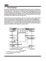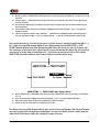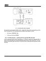
1
C1 Digital to Analog Controller User Manual Dear Client, We are honored that you have chosen the CH C1 Digital to Analog Controller. Our team has put all his efforts into designing and manufacturing this top quality versatile and future-proof product and is proud to present it to you. We hope your C1 will bring you uncountable hours of emotion from your musical collection. But before starting your musical journey, we kindly ask you to pay attention to the information contained in this manual. The C1, as you will discover in the following pages, is a Swiss precision product designed for ultimate performance and flexibility. However, reaching sonic excellence requires your unit to be setup and operated correctly and this what this manual is all about. If you have any questions or require assistance, please don't hesitate to contact your authorized dealer. We hope you will enjoy your C1 D/A Controller for many years. The Concert has just begun... Cossy F. Heeb T. FCC-Notice Note: This equipment has been tested and found to comply with the limits for a Class B digital device, pursuant to Part 15 of the FCC Rules. These limits are designed to provide reasonable protection against harmful interference in a residential installation. This equipment generates, uses and can radiate radio frequency energy and, if not installed and used in accordance with the instructions, may cause harmful interference to radio communications. However there is no guarantee that interference will not occur in a particular installation. If this equipment does cause harmful interference to radio or television reception, which can be determined by turning the equipment off and on, the user is encouraged to try to correct the interference by one or more of the following measures: • adjust or relocate the receiving antenna • increase the separation between the equipment and the receiver • connect the equipment into a mains outlet on a circuit different from that to which the receiver is connected • consult the dealer or an experienced ratio/TV technician for help Disposal – Environmental care Directive 2002/96/EG of the European Parliament requires consumer electro-technical appliances to be disposed separately and have to be indicated with the following symbol. Should you dispose this component please do so in conformity with local and global legal and environmental regulations and according to best practices. We strongly encourage you to recycle any batteries used with this component. Table of contents 1 Technical Highlights.............................................................................................................................................................. 8 1.1 Digital to analog conversion......................................................................................................................................... 9 1.1.1 Clock management............................................................................................................................................. 9 1.1.2 HiD processing engine......................................................................................................................................... 9 1.1.3 D/A conversion stage........................................................................................................................................ 10 1.1.4 Output stage.................................................................................................................................................... 10 1.1.5 Volume control capability.................................................................................................................................. 10 1.2 Mechanical construction............................................................................................................................................. 11 1.3 Modular architecture and slot-in boards...................................................................................................................... 11 1.3.1 Digital inputs and CH Link: DIGITAL_IN board.................................................................................................... 12 1.3.2 USB Audio inputs: USB_IN board option............................................................................................................. 12 1.3.3 Analog inputs: ANALOG_IN board option........................................................................................................... 12 1.3.4 External clock synchronization: SYNC_IO board option........................................................................................ 12 1.3.5 Ethernet streaming: NETWORK board option....................................................................................................... 13 1.4 Power supply............................................................................................................................................................ 13 1.4.1 Optional external power supply......................................................................................................................... 13 2 Before Use........................................................................................................................................................................ 14 2.1 Package content........................................................................................................................................................ 14 2.2 Safety notice............................................................................................................................................................. 14 2.3 User Manual............................................................................................................................................................. 15 2.4 Mains supply............................................................................................................................................................. 15 2.5 Transport and packaging............................................................................................................................................ 15 2.6 Cleaning................................................................................................................................................................... 16 2.7 Maintenance and service............................................................................................................................................ 16 3 Installation........................................................................................................................................................................ 17 3.1 Unpacking................................................................................................................................................................ 17 3.1.1 Removing the security screw.............................................................................................................................. 17 3.2 Positioning................................................................................................................................................................ 17 3.2.1 Unit position adjustment.................................................................................................................................... 17 3.2.2 Adjustment shaft covers.................................................................................................................................... 18 3.3 Connections............................................................................................................................................................... 19 3.3.1 CONTROL board................................................................................................................................................ 20 3.3.1.1 USB port.................................................................................................................................................. 21 3.3.1.2 Ethernet port........................................................................................................................................... 21 3.3.2 NETWORK board............................................................................................................................................... 21 3.3.2.1 USB port.................................................................................................................................................. 21 3.3.2.2 Ethernet port........................................................................................................................................... 21 3.3.3 DIGITAL_IN boards........................................................................................................................................... 21 3.3.3.1 Standard digital inputs............................................................................................................................. 22 3.3.3.2 CH Link digital audio interface.................................................................................................................. 22 3.3.4 USB_IN boards................................................................................................................................................. 22 3.3.4.1 Microsoft Windows configuration (XP, Vista, 7 and 8).................................................................................. 23 3.3.5 ANALOG_IN boards.......................................................................................................................................... 23 3.3.6 SYNC_IO board................................................................................................................................................ 24 3.3.6.1 BNC clock input........................................................................................................................................ 24 6 C1 User Manual Rev 1.9 3.3.6.2 BNC clock outputs..................................................................................................................................... 25 3.3.7 Power cord receptacle and voltage selection....................................................................................................... 25 3.3.8 External power supply connector....................................................................................................................... 25 4 Operation.......................................................................................................................................................................... 26 4.1 Front panel controls................................................................................................................................................... 26 4.1.1 Front panel...................................................................................................................................................... 26 4.1.2 User control knob............................................................................................................................................. 26 4.2 Operating modes....................................................................................................................................................... 28 4.2.1 Normal mode................................................................................................................................................... 28 4.2.2 Shortcuts.......................................................................................................................................................... 29 4.2.3 Menu mode...................................................................................................................................................... 31 4.3 Configuration............................................................................................................................................................ 34 4.3.1 C1 configuration menu items............................................................................................................................. 35 4.3.1.1 AUDIO SETTING........................................................................................................................................ 35 4.3.1.2 DISPLAY SETTING...................................................................................................................................... 38 4.3.1.3 SHORTCUTS.............................................................................................................................................. 40 4.3.1.4 FACTORY SETTING..................................................................................................................................... 41 4.3.1.5 INSTALLED OPTIONS................................................................................................................................. 42 4.3.1.6 NETWORK................................................................................................................................................ 43 4.4 Remote control.......................................................................................................................................................... 44 4.4.1 Remote control operation.................................................................................................................................. 44 4.4.2 Changing the remote control batteries................................................................................................................ 45 4.5 Advanced clocking..................................................................................................................................................... 45 4.5.1 General clocking considerations......................................................................................................................... 45 4.5.2 Without SYNC_IO board.................................................................................................................................... 45 4.5.3 C1 D/A controller (with SYNC_IO board) + D1 SACD/CD drive (with SYNC_IO board)..........................................46 4.5.4 3x C1 D/A controllers + multichannel D1 drive (all with SYNC_IO board)............................................................47 4.5.5 C1 D/A controller + Computer (USB audio)........................................................................................................ 49 4.5.6 C1 D/A controller + Computer (Ethernet audio streaming).................................................................................. 49 4.6 Returning to Factory defaults..................................................................................................................................... 50 5 Firmware update............................................................................................................................................................... 51 5.1 Introduction.............................................................................................................................................................. 51 5.2 Firmware Update procedure....................................................................................................................................... 51 5.2.1 Preparing the firmware image........................................................................................................................... 51 5.2.2 Updating the firmware (Firmware Update procedure)......................................................................................... 52 5.2.3 Emergency Firmware Update procedure............................................................................................................. 52 6 Troubleshooting................................................................................................................................................................. 54 7 Specifications..................................................................................................................................................................... 56 7.1 Specifications............................................................................................................................................................ 56 7.2 Dimensions............................................................................................................................................................... 58 7.3 Factory settings......................................................................................................................................................... 59 Rev 1.9 C1 User Manual 7 1 Technical Highlights CH products are proudly designed and manufactured in Switzerland by CH Precision Sàrl. Our engineers have put all their knowhow into bringing you the C1, a top performances future-proof digital to analog (D/A) controller, based on slot-in boards and USB flash-drive firmware update. In its base version the C1 is a four inputs D/A converter, with integrated preamplifier functions such as source selection and volume control. Default configured C1 have one DIGITAL_IN board and a CONTROL board. Audio inputs on each DIGITAL_IN board include three standard digital audio connectors (RCA coaxial S/PDIF, TOSLINK optical S/PDIF and XLR AESEBU) supporting S/PDIF encoded PCM up to 24bits/192kHz, as well as proprietary high definition CH Link interface, supporting both I2S PCM (up to 32 bits/768kHz) and native DSD audio signal connection. Optional boards allow to extend the functionality of the base version of the C1 D/A controller. By adding extra DIGITAL_IN boards (a total of up to three input boards can be plugged in the unit), the C1 can be connected to even more standard digital sources. Addition of optional USB_IN board and/or optional NETWORK Ethernet streaming board (replaces standard CONTROL board) unleashes the full capabilities of the C1 as the ultimate high-resolution computer audio file player. On the other hand, ANALOG_IN optional board will turn your C1 into a top quality preamplifier while offering single-ended RCA and balanced XLR analog inputs. Finally, the SYNC_IO optional board provides advanced clock synchronization capabilities for use with external clock generators or to enslave the D1 SACD/CD drive to the C1's Masterclock for zero-jitter connection. (1) (9) (2) (10) (3) (3) (4) (11) (12) (5) (13) (6) (7) (3) (3) (8) (14) C1 main components (1) External power supply input. For X1 optional external power supply only (2) Mains switch and power cord receptacle (on back panel) (3) Adjustment shafts and screws 8 C1 User Manual Rev 1.9 (4) (5) (6) (7) (8) (9) (10) (11) (12) (13) (14) Power supply section Main power transformer Standby power transformer (ensures green mode Standby) Power supply regulation board AMOLED display (on front panel) Audio in, clock in/out, USB (firmware update) and RJ-45 (control/network) connectors (from slot-in boards). Analog ground to Earth jumper Slot-in boards (SYNC_IO, CONTROL/NETWORK, DIGITAL_IN/USB_IN/ ANALOG_IN) Main processing and control board Left channel DAC board Right channel DAC board Concentric push control knob 1.1 Digital to analog conversion The C1 D/A controller is built around a synchronous CH-HiD processing engine feeding two first grade factory-calibrated monaural D/A conversion boards. The conversion stage is a linearized R2R topology, followed by a fully discrete output stage. The whole purpose of this design is not only to reconstruct correct level information but also perfect timing, since it is the key element for recreating nature-like immersion into a musical performance. 1.1.1 Clock management The first requirement to achieve perfect timing is that audio data are fed into the DAC chips synchronously to a jitter-free clock. This is why two high-precision low-drift audio crystal clock oscillator (22.5792 MHz for 44.1 kHz multiples and 24.576 MHz for 48 kHz multiples) are located only a few cm from the DAC chips. The clocking section has its owns dedicated power supply fully decoupled (complete galvanic isolation) from all noisy digital signals. This critical Masterclock signal is carried to the DAC chips in LVDS (low-voltage differential signaling) form to avoid any cross-talk pollution. In order to be synchronous to the incoming audio signal, these crystal oscillators can be fine tuned using a voltage controlled feedback (VCXO), computed by a proprietary algorithm. Performances of this “digital phase-locked loop” (digital PLL) is jitter rejection below 0.1 Hz, while frequency tracking is achieved through sub 0.1 PPM correction steps. Phase alignment is also guaranteed with a +/-2.5 us accuracy. When combined with matching CH D1 SACD/CD drive and optional synchronization boards (or a computer source), the C1 can even be configured as the clock master, having the source (either CH D1 or computer) clockenslaved. In such configuration, the jitter is completely removed from the system. 1.1.2 HiD processing engine After years of development in the high-end audio industry we came to the conclusion that the digital samples contained in the original audio stream should remain untouched, only computing missing information between them to remove most of the burden (and phase non-linearity) off the analog filtering stage. Compared to widely-used asynchronous sample rate conversion (ASRC), synchronous up-sampling removes all harshness often found in digital players. Rev 1.9 C1 User Manual 9 The 4.8GFLOPS DPS engine used for each channel performs several tasks, including synchronous up-sampling (to 705.6/768 kHz), DSD to PCM conversion (for DSD layer playback of SACDs), volume control, resolution enhancement and linearity enhancement (proprietary scrambling algorithm). 1.1.3 D/A conversion stage The digital to analog conversion stage of each channel is handled by four Burr-Brown PCM 1704 R2R chips. While total harmonic distortion (THD) figure of top R2R conversion chips (such as PCM 1704 used in C1) is slightly less impressive than those of Delta-Sigma technology based converters, their temporal behavior (on transient events which music is filled with) is inherently better. The high frequency behavior (above 20 kHz) is also much more accurate and free from modulation noise that often disrupts treble speakers (tweeters), as high energy content into the 20 kHz -100 kHz band can not be handled properly by most tweeters. Combining four PCM 1704 the way it is done in the C1 enables improved THD figures compared to individual conversion chips and to exploit their full output range (scrambling) which leads to an enhanced linearity, especially for small signal modulation (which is common in the C1, especially when used as a preamplifier with volume control). In order to achieve reproductive audio performances through our production, each chip used for a single channel should be identical, including gain and offset. Unfortunately, tolerances on these parameter is rather loose. In order to avoid costly manual component measurement and matching (or disparity of the audio performance of a production batch), we have introduced a fully automated calibration process that is factory-performed, and can also be run by customer to keep top performances over time. During this calibration process, the DSP sets several codes to each individual DAC chip, while a dedicated analog to digital converter (ADC) measures the resulting voltage. The DSP is then able to compensate for any disparity across DAC chips on a DAC board. 1.1.4 Output stage Each PCM 1704 chip outputs an analog current which reflects the digital code fed to the C1. It is first converted by an ultra-fast current to voltage stage (I-V). The bandwidth of this stage has to be very wide, in order not to distort (i.e. add harmonic distortion) the staircase shape of the sample-and-hold DAC chip output. A fully discrete low-pass filter without feedback comes next, to smooth out the voltage signal without generating in-band phase shift. Finally, a differential output stage with high output current capability follows, driving single-ended 75 Ohm WBT nextgen RCA, single-ended 50 Ohm BNC and fully-balanced Neutrik XLR connectors. 1.1.5 Volume control capability The C1 can be used as a pure DAC (digital to analog converter) together with an analog preamplifier. But it can also be used as a controller, directly feeding power amplifiers. In that case, it allows volume control in the range of -95.5 dB to +24.0 dB (with 0.5dB steps), with full muting capability when volume is turned lower than -95.5 dB. Positive gain (+0.5 dB to +24.0 dB) is only possible when the incoming signal is lower than 0 dBFS (full scale). Otherwise, the C1 will automatically decrease the volume in order to avoid any clipping. Left/right balance correction is also available in a +/- 6dB range (with 0.5dB steps). 10 C1 User Manual Rev 1.9 Volume control is achieved by a combination of analog attenuators and high resolution digital multiplication. When the volume is set in the range -95.5 dB to -12.5 dB, a 12 dB analog attenuator in engaged, and the DSP attenuates (i.e. multiply the audio sample in 32 bits floating point resolution) by [volume + 12 dB]. When the volume is set between -12.0 dB and -6.5 dB, a 6 dB analog attenuator in engaged, and the DSP attenuates by [volume + 6 dB]. When the volume is in the range -6 dB to 0dB, no analog attenuator is engaged, and the DSP attenuates by [volume]. When the volume is positive (i.e. +0.5 dB to +24.0 dB), no analog attenuator is engaged, and the DSP applies a positive gain corresponding to [volume], whenever possible. If the DSP detects that the upcoming resulting samples will digitally clip (sample value * volume > 0 dB full scale), it will soft clip this event and automatically decrease the volume to a value that will avoid clipping in the future. 1.2 Mechanical construction The C1 D/A controller is assembled from high-quality aluminum and steel elements with no visible screws on the front, top and side panels. The front panel, base, side panels and top cover are machined from aluminum. The power supply is isolated from the audio section in its own compartment to avoid any contamination of the audio circuits by noise radiated from the supply. Pin assembly of all chassis elements provides smooth joints between elements while screws every 6cm ensures protection against electromagnetic interferences. First class mechanical and chemical surface treatments provide the luxury finish of the C1. Four steel feet support the unit. Each feet ends with a elastomer ring to sit on delicate surfaces but is also equipped with a height adjustable steel spike to fine tune unit positioning. Horizontal adjustment is done with the provided screwdriver through the four adjustment shafts accessible from the top of the unit. In addition to providing convenient horizontal adjustment from the top of the unit, the shafts also serve as vibration evacuation channels for any stacked unit. Special shaft covers are provided to interface with the spikes of the stacked unit. Any vibration from the upper unit is transmitted by the shaft cover to the shaft and from the shaft to the lower unit feet or spike, forming a privileged path for vibrations evacuation. 1.3 Modular architecture and slot-in boards The C1 benefits from a fully modular architecture. It features separated sections for power-supply, front panel, computing + signal/clocks routing + central host processor, slot-in boards and monaural conversion boards. This modular architecture combined to the USB plug for all firmwares (MCU, DSPs and FPGAs) update allows for easy servicing and upgrade should one section become faulty or obsolete. The slot-in boards section consists in a vertically mounted mother board with optional boards plugged into it. Optional boards provide audio functionality and connectivity to other equipment. There are six types of slot-in boards: • DIGITAL_IN: provides three standard digital audio input plus a proprietary CH-link input • USB_IN : provides asynchronous USB audio (up to 24bits/192kHz) input. Computer is enslaved to the C1, sending audio packets a a C1-specified rate Rev 1.9 C1 User Manual 11 • ANALOG_IN: provides single-ended RCA and balanced XLR analog audio input • SYNC_IO: provides advanced clock synchronization options (1 clock in, 2 clock out) • CONTROL: provides a USB port for software upgrade and an Ethernet port for command • NETWORK: optional board used to upgrade the CONTROL board slot. Provides a USB port for software upgrade and an Ethernet port for high resolution audio streaming and command There are five slots in the C1. Three of them can be populated with any combination of DIGITAL_IN, USB_IN and ANALOG_IN boards. One of them is dedicated to the optional SYNC_IO board while the last one is default loaded with a CONTROL board, but can be upgraded to a NETWORK board for Ethernet streaming capability. Note that optional boards MUST be installed by a qualified technician. Failure to do so will void any warranty. 1.3.1 Digital inputs and CH Link: DIGITAL_IN board Each DIGITAL_IN board provides standard digital inputs in XLR (AES-EBU), Coaxial RCA (S/PDIF) and Optical TOSLINK (S/PDIF) formats as well as in the CH Link high-definition proprietary format. CH Link uses a dedicated connector to carry high resolution audio and control data over a single link between CH units. It supports both PCM (up to 768kHz, 32bits) and DSD. To comply with high definition digital content protection, DSD signals are cyphered when transported over CH Link from the D1 to the C1. On its standard digital input connectors, C1 can lock to incoming S/PDIF modulated 16 or 24 bits PCM audio, at sample rates of 44.1, 48, 88.2, 96, 176.4 or 192 kHz, +/- 80 PPM. 1.3.2 USB Audio inputs: USB_IN board option The USB_IN board provides asynchronous UBS audio input. Asynchronous mode means that the C1 is the clock master, and the computer is the clock slave. Therefore no jitter is imported from the computer world. Moreover, all noisy digital devices on this board (such as the DSP) are powered by the USB port (i.e. by the computer), and are galvanic isolated from the rest of the C1. The USB input can be configured (in C1's menu) as audio class 1.0 (no driver required, Fs limited to 96kHz) or as audio class 2.0 (a provided driver is needed for Microsoft Windows XP/Vista/7 systems, Fs up to 192kHz are supported). 1.3.3 Analog inputs: ANALOG_IN board option The ANALOG_IN board features stereo analog input on two connector pairs: a single-ended RCA pair and a balanced XLR pair. The analog stage design is fully discrete. One can find high-grade A/D conversion chip on this board, using the same high-precision low-jitter clock signals as the two monaural DAC boards. The analog data are sampled at the rate of 5.6448 MHz (DSD2x) before entering one 32 bit floating point DSP per channel. This option turns the C1 into an analog preamp. 1.3.4 External clock synchronization: SYNC_IO board option The SYNC_IO board provides advanced clock synchronization options for C1 when used with an external clock generator or matching CH source (such as the D1). It includes a clock input on BNC connector with selectable 75 Ohm or high input impedance. Supported input frequencies on this connector are all standard audio Wordclocks (44.1, 48, 88.2, 96, 176.4 and 196 kHz), audio Masterclocks (22.5792 and 24.576 MHz), DSD bitclock (2.8224 MHz) and atomic-clock multiples (100 kHz and 10 MHz). When fed with an audio Wordclock, the C1's internal clock will lock its VCXO internal clock in frequency and in phase (phase accuracy of 12 C1 User Manual Rev 1.9 +/- 2.5 us), tracking below 0.1 Hz with 0.1 PPM corrections for optimal jitter rejection. Two 75 Ohm Wordclock outputs completes the input/output capabilities of the SYNC_IO board. When C1 is matched with a D1, both equipped with a SYNC_IO board, the optimal configuration is to set the C1 as the clock master (C1 clock source: INTERNAL), and D1 as the clock slave (D1 clock source: SYNCHRO BNC 75). In that case, connect one of C1's BNC clock out to D1's clock in configured as a 75 Ohm input with a 75 Ohm BNC-terminated cable. 1.3.5 Ethernet streaming: NETWORK board option The CONTROL board can be replaced by a NETWORK board, providing all the features of the CONTROL board, plus Ethernet based audio streaming. Once a musical server is installed and configured properly, simply connect the C1's Ethernet plug to you local network to use it as an audio renderer. High resolution audio format are supported, and the complete system is enslaved to the C1's internal clock for jitter-free playback. 1.4 Power supply The power supply of the C1 is a linear supply with multiple independent local regulations. It is based on an oversized magnetically shielded toroidal mains transformer and includes a mains filter. A secondary (also toroidal) transformer is used as Standby transformer to ensure green Standby mode, meeting the latest energy saving regulations. Both transformers have static shields between primaries and secondaries. They are mounted on a separate steel plate which is isolated from the main base aluminium plate by silent blocks. Discrete (power-transistor and op-amp based) ultra low noise regulators are used throughout the power supply and special care has been paid to the Masterclock power supply. The Masterclock benefits from its own dedicated supply, completely decoupled from the noisy digital and motor sections. This ensures an ultra-low jitter clock source for the whole system. Input AC voltage to the power supply can be set to 100V, 115V or 230V AC depending on your local mains voltage. 1.4.1 Optional external power supply The C1 is equipped with an external power supply input. This input is dedicated to the CH X1 external power supply. When the external power supply is connected, the internal power supply of the C1 is turned-off (only the Standby transformer remains active). Turning the internal power supply off ensures that no power supply induced noise or radiations are generated inside the C1 unit, thus permitting optimal operating conditions for the circuits. Rev 1.9 C1 User Manual 13 2 Before Use Please read the following carefully. 2.1 Package content Make sure that the package content is complete. If not, please contact your authorized dealer. Your package should contain: • C1 D/A controller • Power cord • Accessory box • User Manual (this manual, located in the accessory box) • C1 D/A controller Service Booklet with warranty card (located in the accessory box) • Remote control (located the in the accessory box) • Adjustment screwdriver (located in the accessory box) • 4x adjustment steel spikes (located in the accessory box) • 4x adjustment shafts steel stacking covers (located in the accessory box) • 4x adjustment shafts aluminum top covers (located in the accessory box) Please store the packaging material for future transportation. Check your C1 D/A controller for apparent damages. In case of damage, please contact your authorized dealer. If your C1D/A controller is still very cold from transport, please let it warm up to room temperature in order to avoid condensation inside the unit. 2.2 Safety notice Make sure to observe the following rules: 14 • Install your C1 D/A controller on a stable base • Do not install your C1 D/A controller near water • Always handle with care. The C1 D/A controller is quite heavy, so have someone help you when moving it around • Do not expose the unit to any kind of liquid C1 User Manual Rev 1.9 • Do not install in direct sun light or near any heat source such as radiators or other apparatus generating heat • Do not install in a confined space and make sure sufficient air can flow around the unit • Do not operate under high ambient temperature (>40°C) or with extremely high humidity such as in humid cellars • Only use options and accessories specified or recommended by the manufacturer • Do not open the unit nor try to service it by yourself. Do not try to install any option board by yourself. Always refer to a qualified technician for service, maintenance or upgrades. Failure to do so will void the unit's warranty 2.3 User Manual Please read this manual carefully before making connections or operating your C1 D/A controller. After reading, store the manual in an accessible place for future reference. If, after reading this manual, you feel unsure about how to make connections or how to operate the unit, please contact your authorized dealer. 2.4 Mains supply Make sure to use 3 terminals (phase, neutral and earth) power cords with ground conductor. Make sure that the mains voltage selection of the unit matches your mains voltage. Make sure your C1 D/A controller is disconnected from AC wall power in the following cases: • When making connections (it is also recommended to disconnect the rest of the system from AC wall power) • When cleaning • During thunder storms • When unused for a long period 2.5 Transport and packaging The C1 D/A controller must always be stored in its original packaging for transportation. Doing so will ensure optimal level of protection of your unit. Therefore, keep all the packaging material in a dry and clean place for future use. In addition, the transformer base plate must be secured for transportation to avoid excessive constraints on the silent blocks isolating the chassis from transformer vibrations. This is done by the insertion of a security screw on the bottom of the unit. Do not forget to install this screw for transportation and to remove it at installation of the unit in its new location. Finally we recommend to remove the adjustment spikes and to put them into the accessory box for transportation. Indeed, Rev 1.9 C1 User Manual 15 vibrations during transport may cause the adjustment spikes to move from their fully retracted position. There is risk of scratching the installation base if the spikes are not fully retracted when installing the unit. 2.6 Cleaning Use a soft, dry towel or cloth for cleaning. Never use any solvent or liquids as they may damage the surface treatment or penetrate inside the unit. 2.7 Maintenance and service The C1 D/A controller contains no user serviceable parts. Do not try to open, modify or repair your C1 by yourself. This will void any warranty. Your C1 D/A controller must be checked by a qualified technician in any of the following cases: 16 • The unit is not functioning properly • The mains cable or the power cord receptacle is damaged • The unit has been dropped to the floor or presents external damage • The C1 D/A controller has been exposed to liquids (such as rain) or unknown substances C1 User Manual Rev 1.9 3 Installation 3.1 Unpacking Unpack the C1 D/A controller and store the packaging for future transportation. Be careful when lifting the C1 as the unit is heavy (over 20kg). Get someone to help you if necessary. When unpacking and installing the C1, take care not to damage the high quality surface treatments. 3.1.1 Removing the security screw The transformer base plate must be secured during transportation to avoid damage to the isolating silent blocks. The security screw is located at the bottom of the unit. To remove the security screw, tilt the unit on its side and unscrew. Do not tilt the unit on the front or back panels as this may damage the user control knob or the connectors. (1) Security screw location (1) Security screw. Must be mounted for transport and removed at installation 3.2 Positioning Position the C1 unit on a stable base. Make sure cooling air is able to freely flow around the unit. 3.2.1 Unit position adjustment The C1 D/A controller is equipped with height adjustable feet. More precisely, each feet has an internal height adjustable spike which can be accessed with the provided adjustment screwdriver through the adjustment shafts. When delivered from factory, the adjustment spikes are not mounted in the feet but are located in the accessory box. Remove the adjustment spikes from the accessory box and put one into each adjustment shaft. Place the provided screwdriver into the adjustment shafts and turn clockwise to secure the spikes and make the required adjustments. Rev 1.9 C1 User Manual 17 When the spikes are fully retracted, the C1 sits on elastomer rings to protect the base. If the base on which the C1 is located is fragile or should not be scratched, please make sure to use the optional CH support discs to protect the base. ( 1) ( 1) ( 2) ( 2) ( 2) ( 2) ( 3) ( 1) ( 3) ( 3) ( 1) ( 3) ( 4) Adjustment shafts, feet and spikes (1) (2) (3) (4) Adjustment shafts. Insert adjustment spikes and use screwdriver to secure and adjust individual feet spikes Feet Adjustment spike heads (when inserted into adjustment shafts) Adjustment spike 3.2.2 Adjustment shaft covers Once the position of the unit is adjusted, place the appropriate shaft covers on the four adjustment shafts. There are two types of shaft covers delivered with your C1 unit. One type of shaft cover (stacking cover, made of steel) is used when different CH units are stacked. This type of cover includes a receptacle to receive the corresponding spike of the unit placed just above. By doing so, mechanical vibrations are optimally transmitted to ground and minimized inside CH units. The second type of shaft cover (top cover, made of aluminum) can be used when units are not stacked or for the top unit when stacked. It covers the shaft and provides a smooth finish to the top of the unit. Shaft covers are located in the accessories box delivered with your C1 unit. Never stack any component other than CH's on your C1. Never use the aluminum shaft covers (top covers) when another CH component is to be stacked on top of your C1. Shaft covers (left: stacking cover, right: top cover) 18 C1 User Manual Rev 1.9 3.3 Connections This section provides information about how to connect your C1 D/A controller to your system. As the C1 is a modular design with different optional boards, the description applies to the example configuration presented below. If your options do not match the example or you don't feel secure with the connections to be applied to your configuration, please contact your authorized dealer for assistance. The example configuration is a full featured controller with many inputs (standard digital input AES-EBU, Coaxial and Optical, CHLink, USB and balanced and single-ended analog in) and clock synchronization option (SYNC_IO board). This is one of the most complete configurations of C1. If your configuration does not include some of the presented options, just discard the corresponding connections. (1) (2) (15) (3) (4) (5) (16) (17) (18) (6) (7) (8) (9) (10) (11) (19) (20) (21) (22) (23) (12) (24) (25) (13) (26) (14) (27) Rear panel connections (1) (2) (3) (4) (5) (6) (7) (8) (9) (10) (11) (12) (13) (14) (15) (16) (17) (18) Rev 1.9 75 Ohm RCA single-ended analog output for right channel 50 Ohm BNC single-ended analog output for right channel 75 Ohm RCA single-ended analog output for left channel 50 Ohm BNC single-ended analog output for left channel BNC clock input. Provides 75Ohm or Hi-Z input. [optional SNYC_IO board] Ethernet port for command interface [CONTROL board] or for audio streaming and commands [optional NETWORK board] TOSLINK (S/PDIF) digital input [DIGITAL_IN #1 board] AES-EBU digital input [DIGITAL_IN #1 board] USB audio [optional USB_IN board] RCA single-ended analog input for left channel [optional ANALOG_IN board] XLR balanced analog input for left channel [optional ANALOG_IN board] Earth connector. Internally connected to digital ground External power supply connector for X1 power supply option Power on/off switch XLR balanced analog output for right channel XLR balanced analog output for left channel BNC 75 Ohm clock output 2. [optional SYNC_IO board] BNC 75 Ohm clock output 1. [optional SYNC_IO board] C1 User Manual 19 (19) (20) (21) (22) (23) (24) (25) (26) (27) USB port for software upgrades. [CONTROL board or optional NETWORK board] CH Link digital input [DIGITAL_IN #1 board] Coaxial (S/PDIF) digital input [DIGITAL_IN #1 board] RCA single-ended analog input for right channel [optional ANALOG_IN board] XLR balanced analog input for right channel. [optional ANALOG_IN board] Analog ground connector 2 Analog ground connector 1.Can be connected to digital ground (Earth) using provided jumper Power fuse and voltage selection Power cord receptacle The CONTROL board is mandatory in any C1 configuration and is always factory installed. It can be upgraded by an optional NETWORK board that replaces it, covering all functions of the CONTOL board plus audio streaming capability. Depending on optional boards and their arrangement in the C1's expansion slots, connector arrangement may differ on your unit. Each C1 unit provides 4 expansion slots supporting any combination of the following optional boards (note that one slot is dedicated to the SYNC_IO board): • DIGITAL_IN boards (one is already installed in the default C1 configuration) provides 4 digital inputs (coaxial S/PDIF, optical TOSLINK, AES-EBU and CH-Link) • USB_IN boards provides an asynchronous USB audio input • ANALOG_IN boards provides 2 pairs (L+R) or analog inputs (balanced XLR and single-ended RCA) • SYNC_IO board for external clock synchronization Note that only one SYNC_IO board is allowed. Optional input boards can be placed in any slot. Installation of optional boards must be done by a qualified technician only. Do not attempt to install any optional board by yourself as this would void the unit's warranty. 3.3.1 CONTROL board The CONTROL board is factory installed into the C1. It provides a USB port for software updates and an Ethernet port for controlling the unit over a network. Following drawing shows the layout of the back panel of the CONTROL board: CONTROL board back panel layout 20 C1 User Manual Rev 1.9 3.3.1.1 USB port The USB port on the CONTROL board is dedicated to the firmware update of the C1 unit. Do not use it for any other purpose. For more information on unit firmware update, please refer to the corresponding section of this manual. 3.3.1.2 Ethernet port The Ethernet port on the CONTROL board is dedicated to network based control of the unit. This functionality is currently not implemented, thus leave the Ethernet port unconnected. A future C1 firmware release will provide this functionality. 3.3.2 NETWORK board The optional NETWORK board can replace the default CONTROL board. It provides all the features of the CONTROL board (firmware update USB port, control through RJ45 Ethernet port). But its main feature is to convert the C1 into a network streamer when connected to a music server through a LAN. Following drawing shows the layout of the back panel of the NETWORK board: NETWORK board back panel layout 3.3.2.1 USB port The USB port on the NETWORK board is dedicated to the firmware update of the C1 unit. Do not use it for any other purpose. For more information on unit firmware update, please refer to the corresponding section of this manual. 3.3.2.2 Ethernet port The Ethernet port on the NETWORK board has two purposes: music streaming and network-based control of the unit. 3.3.3 DIGITAL_IN boards DIGITAL_IN boards provide digital audio input capabilities. Additional DIGITAL_IN boards (#2 and #3) can be added to the default factory installed DIGITAL_IN #1 into C1 to add inputs of each type. DIGITAL_OUT boards provide both standard (AES-EBU, Coaxial and Optical) digital audio inputs and a proprietary (CH Link) high-definition digital audio interface. Following drawing shows the layout of the DIGITAL_IN board connectors: Rev 1.9 C1 User Manual 21 DIGITAL_IN boards back panel layout 3.3.3.1 Standard digital inputs Each DIGITAL_IN board provides three standard digital inputs: AES-EBU (carrying consumer encoding), Coaxial (S/PDIF) and Optical (TOSLINK). Audio format supported are 16 or 24 bits, 44.1, 48, 88.2, 96, 176.4, 192 kHz sampling frequency. 3.3.3.2 CH Link digital audio interface Each DIGITAL_IN board includes a CH Link proprietary digital audio interface. This interface carries both complete audio stream and control information. Use this link as the preferred interface when connecting your C1 to CH sources such as D1 SACD/CD unit. The proprietary CH Link digital audio interface allows for high definition uncompressed digital audio transfer and supports both DSD and PCM (up to 705.6 / 768 kHz). For digital content protection reasons, the native DSD stream is cyphered on the CH Link interface. Of course, all CH sources (such as D1) and receivers (such as C1) use the same encoding/decoding key. 3.3.4 USB_IN boards Optional USB_IN board provides connectivity to a USB port of a computer. Audio is sent from the computer to the C1 at a rate that is synchronous to the C1's precision internal Masterclock. Following drawing shows the layout of the USB_IN board connector: Asynchronous High Resolution USB Audio input USB In Inputs #1 USB_IN boards back panel layout Apple MAC OS X Snow Leopard V10.6.4 or above natively supports USB Audio Class 2.0, allowing 24bits/192kHz files playback. 22 C1 User Manual Rev 1.9 Microsoft Windows (XP, Visa, 7 and 8) so far only supports USB Audio Class 1.0 by default, limiting the playback to 24bit/96kHz files. Installing the driver provided with optional USB_IN board enables MS Windows computer to support USB Audio Class 2.0, thus allowing 24bit/192kHz files playback. DSD files need USB Audio Class 2.0 to be active and they are packed into a 24bit/176.4kHz PCM-like signal for bitstreaming. The C1 supports the DSD over PCM (DoP1.0) format, automatically unpacks it and converts the DSD bitstream without any loss. 3.3.4.1 Microsoft Windows configuration (XP, Vista, 7 and 8) Foobar (ASIO) http://www.foobar2000.org V1.1, freeware Configuration Driver Required component Output support MS Windows OS USB Audio Class The C1 USB Audio input should not be the MS Windows default audio output device. In addition, Windows should be configured to allow applications to get exclusive access to the C1 USB Audio input. Below is a list of recommended media players, drivers and related configurations to be used with the C1 USB audio input. Buffer 8s 1.0 XP, Vista, 7, 8 ASIO foo_asio asio4all 2.0 XP, Vista, 7, 8 ASIO foo_asio CH USB driver xVyz.zip Output 24bits J. River Media Center (WASAPI) 1.0 Vista, 7, 8 http://www.jriver.com V15, commercial 2.0 Vista, 7, 8 WASAPI EVENT STYLE - H/w buffer = 50ms Output 24bits WASAPI EVENT STYLE - H/w buffer = 50ms Output 24bits Default J. River Media Center (ASIO) http://www.jriver.com V15, commercial 1.0 XP, Vista, 7, 8 ASIO - asio4all 2.0 XP, Vista, 7, 8 ASIO - CH USB driver xVyz.zip Default AlbumPlayer (ASIO) http://www.albumplayer.com V5.2, commercial 1.0 XP, Vista, 7, 8 ASIO - asio4all 2.0 XP, Vista, 7, 8 ASIO - CH USB driver xVyz.zip Buffer = 2048 samples Buffer = 2048 samples Recommended media players, drivers and related configurations 3.3.5 ANALOG_IN boards ANALOG_IN boards provide analog audio input capabilities. Even though the C1 is primarily a high grade digital to analog converter, adding one or two ANALOG_IN boards turns it into a complete preamplifier with both analog and digital inputs. Each ANALOG_IN board adds one RCA single-ended analog input pair and one XLR balanced analog input pair. In order to achieve optimum performance from an analog source, the ANAOLG_IN board converts the incoming analog audio signal into a high resolution digital audio stream (5.6448MHz DSD2x) synchronously to its digital to analog output conversion stage. The volume control is also achieved by an optimized combination of analog attenuators and high precision 32 bits floating point multiplication in the digital domain. Following drawing shows the layout of an ANALOG_IN board connector: Rev 1.9 C1 User Manual 23 ANALOG_IN panel layout 3.3.6 SYNC_IO board The SYNC_IO board is an optional clock synchronization board to be used with an external clock generator or together with other CH products, such as the D1 SACD/CD unit. The board provides one clock input and two clock output on BNC connectors. Each VCXO digital PLL (one is based on a 22.5792 MHz Masterclock and the other one on a 24.576 MHz Masterclock) of the C1 is capable of frequency and phase locking. The frequency is tracked below 0.1 Hz with 0.1 PPM adjustments for optimal jitter rejection. When fed with an audio Wordclock, the C1's internal clock will always keep a phase accuracy below 2.5 us (equivalent to sub-millimeter position accuracy), thus enabling phase perfect match in a multichannel configuration. Following diagram shows the layout of the back panel of the SYNC_IO board: SYNC_IO board back panel layout 3.3.6.1 BNC clock input The SYNC_IO board provides a BNC clock input that can be configured as 75 Ohm input impedance or high input impedance through the C1's menu. Supported input frequencies on this connector are all standard audio Wordclocks (44.1, 48, 88.2, 96, 176.4 and 196 kHz), audio Masterclocks (22.5792 and 24.576 MHz), DSD bitclock (2.8224 MHz) and atomic-clock multiples (100 kHz and 10 MHz). Use this connector to synchronize your C1 unit to an external clock source (atomic clock generator or external source such as CH D1). 24 C1 User Manual Rev 1.9 3.3.6.2 BNC clock outputs Two 75 Ohm output clock connectors are also provided on the SYNC_IO board. Use one of these connectors to synchronize an external device to your C1. Output clock is either a buffered version of input clock (if C1 is synchronized to it input clock), or current audio Wordclock (if C1 is clocked by its internal high precision oscillator). 3.3.7 Power cord receptacle and voltage selection Make sure that the voltage selection is set to the correct value with respect to the AC voltage in your location. Connect the power cord to the power cord receptacle and plug the power plug to an AC wall outlet only after all other connections have been made. 3.3.8 External power supply connector The external power supply connector allows you to connect the X1 optional external power supply from CH. When the X1 is used, it completely replaces the C1's internal power supply, resulting in minimized noise and enhanced audio quality. Note that only the (small) standby transformer of the C1 remains active in this case to ensure the C1's wake up functionality. Rev 1.9 C1 User Manual 25 4 Operation The C1 D/A controller is operated either from the front panel or from the IR remote control. Feedback to the user is provided by a high-definition AMOLED display with customizable colors. Setup operations are exclusively handled from the front panel. 4.1 Front panel controls 4.1.1 Front panel (1) (2) (3) (4) Front panel elements (1) (2) (3) (4) Standby LED User control knob (dual concentric rotatory knob with push function) IR remote control receiver Display area (high-definition AMOLED display The standby LED lights up when the unit is in standby. It is normally turned-off during operation and shortly lights up whenever it receives a valid IR remote control command. The LED can also be programmed to remain on during operation if the display is turned off. The display is a high-definition AMOLED panel with very wide viewing angle, high contrast and high brightness ensuring optimal reading comfort. The color and brightness of the display can be configured according to user's taste and different colors can be chosen for PCM (e.g. CD and most computer audio files format) or DSD (SACD format) playback. 4.1.2 User control knob The user control knob is the main user input device. It is build around a dual concentric rotatory knob with push function, mounted on a Teflon guide. Both the central and the external part of the knob can be moved to the left or the right independently, giving four movements: rotate External Rotate Left/Right [<<E]/[E>>] and Central Rotate Left/Right [<<C]/[C>>]. The central part of the knob also supports a push functionality. There are two types of push: Normal Push [NP] and Long Push [LP]. For a Normal Push, just press the central part of the knob and release it immediately. For a Long Push, press and hold the central part of the 26 C1 User Manual Rev 1.9 knob for 2s or more. ( 1) ( 4) ( 2) ( 5) ( 3) User control knob movements (1) (2) (3) (4) (5) External ring rotate Left [<<E] Central knob rotate Left [<<C] Central knob push. There are two types of push: Normal Push [NP] and Long Push [LP] External ring rotate Right [E>>] Central knob rotate Right [C>>] User Action Code Description [<<C] Central Left: Rotate central knob to the left [C>>] Central Right: Rotate central knob to the right [<<E] External Left: Rotate external ring to the left [E>>] External Right: Rotate external ring to the right [NP] Normal Push: push and release central knob [LP] Long Push: push central knob and maintain for 2s before release User Action Codes Rev 1.9 C1 User Manual 27 4.2 Operating modes The C1 D/A controller has two main operating modes: Normal mode and Menu mode. Normal mode is used to access standard preamplifier controls whereas Menu mode is used to configure the unit. The C1 also includes Shortcuts for quick access to selected Menu mode items. Shortcuts are user programmable and most Menu mode items can be selected as Shortcuts. 4.2.1 Normal mode Normal mode is used for standard preamplifier functions. When powered-on, the C1starts in Normal mode. The display looks as follows: (1) (2) 44.1 > 705.6 kHz (8) (7) 7 -18.5 dB (3) AES EBU 1 <H J AUDIO IN (6) (4) (5) Normal mode display elements (1) Incoming audio sampling frequency (first number, replaced by “DSD” when playing an SACD DSD layer through CH Link) and DSP output frequency (either 705.6 or 768 kHz) feeding conversion chips. Shows the over-sampling (or DSD to PCM conversion) performed by the C1's DSPs. (2) Mute indication. If the 7 symbol is present, the output is muted (3) Analog output level. Only displayed when C1 is used as a preamplifier. When C1 is used as a pure DAC (selectable through C1's menu), output level is set to 0 dB and not mentioned in this display area. (4) Polarity (phase) indication. If the H symbol is present, polarity is reversed (5) External power supply indication. When an external power supply is connected and engaged, < symbol is displayed and internal power supply is turned off (6) Clock source indication (internal, audio in, or clock frequency when an external clock is selected as the clock source) (7) Lock indication (J or K). Tells if the unit is locked to a clock source or not (8) Input source name. Each input source can be renamed through C1's menu 28 C1 User Manual Rev 1.9 Displayed elements depend on the installed optional boards and user settings. In the example above, C1 is playing the audio coming from its first AES-EBU input at the rate of 44.1 kHz, over-sampling it to 705.6 kHz (x16). The output level is -18.5 dB, but is currently muted. C1 has locked its 22.5792 MHz (512 x 44.1 kHz) VCXO to the incoming audio stream. The polarity of the audio signal is inverted, and the C1 is powered through its external DC power supply. Displayed elements for other configurations are similar. Following table shows the actions of the user control knob in Normal mode. User Control Knob Action Unit State Unit Action [NP] Normal Push STANDBY Any other state Wake from STANDBY Enter Shortcuts mode [LP] Long Push STANDBY Any other state Wake from STANDBY Go to STANDBY [C>>] Center Rotate Right D/A Controller (preamplifier) D/A Converter (pure DAC) Increase volume (1st by 0.5 dB steps, then faster) Select next available input [<<C] Center Rotate Left D/A Controller (preamplifier) D/A Converter (pure DAC) Decrease volume (1st by 0.5 dB steps, then faster) Select previous available input [E>>] External Rotate Right Any state Select next available input [<<E] External Rotate Left Any state Select previous available input User control knob actions in Normal mode 4.2.2 Shortcuts The C1 D/A controller is configured by a set of menus as described in the next sections. To allow quick access to the most frequently used configuration menu items, the C1 offers the concept of Shortcuts. Shortcuts are fully programmable and the user may choose any configuration parameter as a Shortcut. There are up to 6 user programmable Shortcuts. To learn how to program individual Shortcuts, please refer to the SHORTCUTS menu item in the next section. For a list of Factory default Shortcuts, please refer to the Specifications section. Shortcuts are accessed from Normal mode by a Normal Push [NP]. Additional Normal Push [NP] skips to the next Shortcut. The last Shortcut is always dedicated to entering the Menu mode (SETUP). On this last Shortcut, a Normal Push [NP] will return to Normal Mode and an External Rotate Right [E>>] (or Central Rotate Right [C>>]) will enter the Menu mode. The individual parameter for a given Shortcut is modified using External Rotate Left [<<E] (or Central Rotate Left [<<C]) and/or External Rotate Right [E>>] (or Central Rotate Right [C>>]) . If there is no user action for about 10s the unit will revert to Normal mode. Following table shows the actions of the user control knob for Shortcuts. User Control Knob Action Unit State [NP] Normal Push Shortcut (except last) Skip to next Shortcut Last Shortcut (SETUP) or Exit Shortcuts mode (Normal mode) after current Shortcut has been modified Rev 1.9 Unit Action C1 User Manual 29 [LP] Long Push Any state As in Normal mode [C>>] Central Rotate Right Shortcuts (except last) Last Shortcut (SETUP) Modify parameter up (when available) Enter Menu mode [<<C] Central Rotate Left Shortcuts Modify parameter down (when available) [E>>] External Rotate Right Shortcuts (except last) Last Shortcut (SETUP) Modify parameter up (when available) Enter Menu mode [<<E] External Rotate Left Shortcuts Modify parameter down (when available) User control knob actions for Shortcuts The PHASE POLARITY Shortcut gives a good illustration of how to navigate a Shortcut screen. Navigating other Shortcuts is similar. (1) PHASE POLARITY INVERSION (6) (5) A IN PHASE ... C OUT OF PHASE (2) (3) (4) PHASE POLARITY Shortcut display elements (1) (2) (3) (4) (5) (6) Shortcut title (Parameter, for other Shortcuts, title changes accordingly) Arrow indicating External Rotate Right [E>>] if applies. The item below indicates the next parameter value (up direction) Next Parameter Value if External Rotate Right [E>>] is applied (parameter up) Current Parameter Value (for other Shortcuts the current Value of the Parameter is displayed on this line) Next parameter value if External Rotate Left [<<E] is applied (parameter down) Arrow indicating External Rotate Left [<<E] if applies. The item below indicates the next parameter value (down direction) The last Shortcut (SETUP) is always the same and cannot be removed or altered. It gives access the Menu mode to access the detailed setup of the unit. 30 C1 User Manual Rev 1.9 (1) DETAILED SETUP EXIT (2) C ENTER (3) (4) SETUP Shortcut display elements (1) (2) (3) (4) Shortcut title. It indicates that Detailed Setup (Menu mode) can be entered at this stage Current value of the parameter. Default action is to exit (go back to Normal mode) Arrow indicating External Rotate Right [E>>] (or Central Rotate Right [C>>]) Next parameter value. If External Rotate Right [E>>] is applied, the unit enters into Menu mode 4.2.3 Menu mode The Menu mode allows for Configuration and Setup of the C1 D/A controller through a set of menus. Menu mode is entered from the last Shortcut item (see above). From Normal mode, enter the Shortcut mode by applying a Normal Push [NP]. By successive Normal Pushes [NP], step to the last Shortcut item (DETAILED SETUP) and apply an External Rotate Right [E>>] to enter the Menu mode. Navigation in Menu mode is based on Central Rotate Left/Right [<<C]/[C>>] to select a given menu item and External Rotate Left/Right [<<E]/[E>>] to change menu level. User Control Knob Action Unit Action [NP] Normal Push Enter next menu level or Validate choice (save setting) [LP] Long Push Puts the unit into Standby [C>>] Center Rotate Right Move to next menu item downward [<<C] Center Rotate Left Move to next menu item upward [E>>] External Rotate Right Enter next menu level [<<E] External Rotate Left Return to previous menu level without saving User control knob actions in Menu mode Rev 1.9 C1 User Manual 31 Following illustration shows the elements of a the C1 SETUP Menu page, the entry point to the C1 menu structure. (1) C1 SETUP AUDIO SETTING DISPLAY SETTING SHORTCUTS FACTORY SETTING FACTORYSETTING INSTALLED OPTIONS NETWORK > Mute Phase polarity Clock source Active input Input gain C (3) (2) C1 SETUP menu display elements (1) Menu title. When entering a menu item, the title also shows the parent menu. If the AUDIO SETTING menu is entered, the title line would display C1 SETUP >> AUDIO SETTING. (2) Shows the accessible parameters when entering the currently highlighted menu item. In this example, AUDIO SETTING is highlighted and the second column shows the parameters accessible in the AUDIO SETTING menu. (3) List of items in the current menu. Navigate from one item to the other using Central Rotate Left/Right [<<C]/[C>>]. To enter the highlighted menu item, use External Rotate Right [E>>] (or a Normal Push [NP]). To go to the previous menu level use External Rotate Left [<<E]. In this example, External Rotate Left [<<E] exits the Menu mode and sets the unit back to Normal mode. Once a menu item is selected by External Rotate Right [E>>], parameters for the corresponding menu item can be navigated and accessed. As an example, the following drawing shows the display elements of the C1 SETUP >> AUDIO SETTING sub-menu. (1) C1 SETUP >> AUDIO SETTING (5) MUTE PHASE POLARITY CLOCK SOURCE ACTIVE INPUT ... Unmuted In phase ... ... (4) (2) (3) C1 SETUP >> AUDIO SETTING menu display elements 32 C1 User Manual Rev 1.9 (1) Menu title. C1 SETUP >> AUDIO SETTING shows that the parent menu is C1 SETUP. By applying External Rotate Left [<<E], the unit returns to the parent menu. (2) A Parameter Value of '...' indicates that the menu items gives access to one or more further sub-menu(s). Further sub-menus have the same structure as this example. (3) This is the Parameter Value column. For each item in the Parameter column, the Parameter Value item on the same line indicates the current value of the Parameter. (4) This is the Parameter column. The currently active Parameter is highlighted. Use Central Rotate Left/Right [<<C]/[C>>] to navigate from Parameter to Parameter. (5) If the first or last item in the Parameter column is indicated by '...' it means that there are additional Parameters not displayed currently onscreen. Use Central Rotate Left/Right [<<C]/[C>>] to navigate towards the '...' to make the corresponding Parameters appear on screen. Once a terminal Parameter (e.g. a Parameter not giving access to a further sub-menu) is selected by External Rotate Right [E>>], the C1 displays the corresponding Parameter adjustment screen. Following example shows the AUDIO SETTING >> PHASE POLARITY Parameter adjustment screen. Other Parameters are similar but may show more (or less) choices for Parameter value. Once a Parameter is set to the desired value, a Normal Push [NP] saves the new Parameter Value and gets back to the parent level (save and exit). On the other hand, an External Rotate Left [<<E] gets back to the parent menu (in the case of this example: AUDIO SETTING), but possible modifications of the Parameter Value are discarded (exit without saving). (1) AUDIO SETTING >> PHASE POLARITY (4) PHASE POLARITY In phase Out of phase (2) (3) AUDIO SETTING >> PHASE POLARITY menu display elements (1) Menu title. AUDIO SETTING >> PHASE POLARITY shows that the parent menu is AUDIO SETTING. To access the parent menu, use External Rotate Left [<<E] (2) The current Parameter Value is highlighted. Use Central Rotate Left/Right [<<C]/[C>>] to navigate through Parameter Values (3) Other possible Parameter Value(s). Number of other Parameter Value(s) depends on Parameter (4) Parameter for which the Parameter Value can be modified in the current menu. The following section gives detailed information about the menu structure and the various Parameters. Note that certain Parameter may or may not appear in the menu depending on installed options. For instance if no ANALOG_IN board is installed, menu items related to the RCA and XLR inputs (enable, gain, renaming) do not appear in the menu. Rev 1.9 C1 User Manual 33 4.3 Configuration Configuration of your C1 D/A controller is accomplished by setting parameters in the Menu mode (see previous section for how to access Menu mode and how to navigate menu items). Following diagram shows the complete menu structure (terminal items not show). Grayed menu items are items which depend on installed optional slot-in boards. Normal mode CH-LINK 1 Shortcut mode SHORTCUT 1 SHORTCUT 2 C1 SETUP C1 SETUP >> AUDIO SETTING Menu mode SHORTCUT N EXIT ENTER AUDIO SETTING >> MUTE AUDIO SETTING >> PHASE POLARITY C1 SETUP >> SET ENCODER CUSTOMIZE ENCODER >> SHORTCUT 1 AUDIO SETTING >> CLOCK SOURCE CLOCK SOURCE >> INPUT CUSTOMIZE ENCODER >> SHORTCUT 2 AUDIO SETTING >> INPUT TYPE INPUT TYPE >> INPUT CUSTOMIZE ENCODER >> SHORTCUT 3 AUDIO SETTING >> INPUT GAIN INPUT GAIN >> INPUT CUSTOMIZE ENCODER >> SHORTCUT 4 AUDIO SETTING >> BALANCE CUSTOMIZE ENCODER >> SHORTCUT 5 AUDIO SETTING >> MONO MODE CUSTOMIZE ENCODER >> SHORTCUT 6 AUDIO SETTING >> PCM FILTER TYPE AUDIO SETTING >> DSD FILTER TYPE AUDIO SETTING >> C1 TYPE AUDIO SETTING >> MAX START VOL AUDIO SETTING >> MAX VOLUME AUDIO SETTING >> USB AUDIO CLASS AUDIO SETTING >> USB AUDIO POWER AUDIO SETTING >> PHONO CURVE SETUP >> DISPLAY SETTING C1 SETUP >> FACTORY SETTING FACTORY SETTING >> FIRMWARE VERSION FACTORY SETTING >> UPDATE FIRMWARE DISPLAY SETTING >> DISPLAY TYPE DISPLAY SETTING >> LED ON/OFF EDIT CUSTOM >> RED DISPLAY SETTING >> BRIGHTNESS PCM EDIT CUSTOM >> GREEN DISPLAY SETTING >> COLOR PCM FACTORY SETTING >> SERIAL NUMBER COLOR PCM >> EDIT CUSTOM DISPLAY SETTING >> BRIGHTNESS DSD FACTORY SETTING >> RESET ALL SETTING DISPLAY SETTING >> COLOR DSD FACTORY SETTING >> SHORTCUTS EDIT CUSTOM >> RED COLOR DSD >> EDIT CUSTOM DISPLAY SETTING >> BRIGHTNESS ANALOG FACTORY SETTING >> INPUT ENABLED FACTORY SETTING >> INPUT GAIN FACTORY SETTING >> INPUT NAMES EDIT CUSTOM >> BLUE EDIT CUSTOM >> GREEN EDIT CUSTOM >> BLUE DISPLAY SETTING >> COLOR ANALOG COLOR ANALOG >> EDIT CUSTOM EDIT CUSTOM >> RED DISPLAY SETTING >> INPUT RENAMING INPUT RENAMING >> INPUT EDIT CUSTOM >> GREEN EDIT CUSTOM >> BLUE FACTORY SETTING >> REMOTE CONTROL FACTORY SETTING >> CALIBRATE FACTORY SETTING >> NETWORK C1 SETUP >> INSTALLED OPTIONS C1 SETUP >> NETWORK NETWORK >> STATUS NETWORK >> CONFIGURE NETWORK >> ANNOUNCE INSTALLED OPTIONS >> SYNCHRO INSTALLED OPTIONS >> ETHERNET INSTALLED OPTIONS >> SLOT 1 INSTALLED OPTIONS >> SLOT 2 INSTALLED OPTIONS >> SLOT 3 C1 D/A controller menu structure 34 C1 User Manual Rev 1.9 There are six main menus used for configuration of the C1: • AUDIO SETTING: Allows to adjust audio related parameters • DISPLAY SETTING: Allows to adjust display related parameters • SHORTCUTS: Allows to assign and modify Shortcuts for user interface customization • FACTORY SETTING: Indicates the software version and allows to update it. Also allows to return to factory settings and calibrate the C1 • INSTALLED OPTIONS: Provides information about the installed optional slot-in boards • NETWORK: Provides information about the network setup and enables its configuration 4.3.1 C1 configuration menu items 4.3.1.1 AUDIO SETTING C1 SETUP >> AUDIO SETTING MUTE PHASE POLARITY CLOCK SOURCE INPUT TYPE ... Unmuted In phase ... ... The C1 SETUP >> AUDIO SETTING menu allows configuration of the audio related Parameters of the unit. Accessible Parameters are: - MUTE: Mutes or unmutes the audio output - PHASE POLARITY: Allows to revert the phase of the audio output - CLOCK SOURCE: Allows to select the clock source for each input - INPUT TYPE: Selects if an input is hidden, and/or volume controlled. - INPUT GAIN: Sets individual gain/attenuation per input - BALANCE: +/-6dB L/R balance correction - MONO MODE: Allows to route left (resp. right) input to both outputs - PCM FILTER TYPE: Digital filter selection for PCM audio - DSD FILTER TYPE: Digital filter selection for DSD audio - C1 TYPE: Enables volume control - MAX START VOL: Sets maximum allowed volume at startup in controller mode - MAX VOLUME: Sets maximum allowed volume in controller mode - USB AUDIO CLASS: Select class 1.0 (96/24 max) or class 2.0 (192/24 max) - USB AUDIO POWER: Allows USB audio section power off when unused - PHONO CURVE: Selects correction curve for phono input board The following table details the Parameters of the AUDIO SETTING menu: PARAMETER PARAMETER VALUES REQUIRED OPTIONS REMARKS MUTE Muted None None Rev 1.9 C1 User Manual 35 Unmuted PHASE POLARITY In phase Out of phase None None CLOCK SOURCE (individually selectable for each input) Audio In SYNC_IO board to Internal Clock choose some of these Synchro BNC (75 Ohm) clock sources Synchro BNC (Hi-Z) SRC Audio In clock source is available in all cases for digital in board inputs. SRC adds an asynchronous sample rate converter stage that allows the C1 to lock even on S/PDIF sources that do not comply with AES requirements. Internal Clock is the the default choice for computer sources (USB audio and Ethernet streaming) where C1 is the clock master. Synchro BNC (75 Ohm) and Synchro (Hi-Z) are only available when the SYNC_IO board is installed. SYNC_IO offers choice of 75 Ohm or highimpedance on its BNC clock input. INPUT TYPE Disabled Normal Processor “Disabled” inputs cannot be selected anymore when scrolling though inputs (with remote control or encoder). For “Processor” inputs, the C1's volume control (in processor mode) is not applied (no attenuation!) Only available inputs (depends on hardware configuration) can be enabled/disabled in the menu INPUT GAIN (individually selectable for each input) -6 dB to +6 dB by 0.5 dB steps None None BALANCE Left +6 dB to Right +6 dB by 0.5 dB steps None None MONO MODE Stereo Mono Left Mono Right None When “Mono Left” (respectively “Mono Right”) is selected, the left (respectively right) audio input is mapped to bot C1's outputs PCM FILTER TYPE Minimum Phase Linear P. apodising Linear P. sharp None Choice of different filter types for PCM audio input. Linear P. indicates linear phase. Sharp corresponds to a steep cut-off. Apodising filters reach full attenuation at half the sampling frequency to minimize transition band aliasing. 36 C1 User Manual Rev 1.9 DSD FILTER TYPE Minimum Phase Linear P. apodising Linear P. sharp None None Choice of different filter types for DSD audio input. C1 TYPE D/A Controller D/A Converter Connected to power amp When C1 is configured as D/A Converter, its output Connected to preamp volume is not attenuated (0dB). This setting should only be selected if C1 is used with an external preamplifier (or integrated amplifier) MAX START VOL -50 dB to -20 dB by 10 None dB steps The startup volume is the lowest of the following: - Last listening volume before standby - MAX START VOL parameter value MAX VOLUME -30 dB to 0 dB by 10 dB None steps, or no limitation (up to +24 dB) Limits the output volume of the C1 in controller mode USB AUDIO CLASS 1.0 or 2.0 USB_IN #1 / #2 More detail in chapter 3.3.4 USB_IN boards USB AUDIO POWER Auto shutdown or Keep USB powered USB_IN #1 / #2 Auto shutdown allows automatic power off of the USB audio board (including its DSP) when another input is selected to minimize noise. In that case, the computer looses connection to the C1 and its playback will stop as another input is selected. Keep USB powered allows quick switching from another input to the USB audio input, as it keeps processing when another input is selected in the C1. PHONO CURVE RIAA RIAA EXT OEC 250 OEC 500 COLUMBIA N78 COLUMBIA LP M33 NAB NARTB AES LGC DECCA CCIR 134 IEC RCA IEC98 TELDEC PHONO_IN Enable to select the optimum phono correction curve for each record Linear P. indicates linear phase. Sharp corresponds to a steep cut-off. Apodising filters reach full attenuation at half the sampling frequency to minimize transition band aliasing. Details of AUDIO SETTING menu Parameters Rev 1.9 C1 User Manual 37 4.3.1.2 DISPLAY SETTING The C1 SETUP >> DISPLAY SETTING menu allows configuration of the display related Parameters of the unit. Accessible Parameters are: - DISPLAY TYPE: Allows to chose what to display - LED ON/OFF: Selects if the LED is turned on when the display is off - BRIGHTNESS PCM: Sets the display brightness for PCM playback - COLOR PCM: Selects the display color for PCM playback - BRIGHTNESS DSD: Sets the display brightness for DSD playback - COLOR DSD: Selects the display color for DSD playback - BRIGHTNESS ANALOG: Sets the display brightness for analog source playback - COLOR ANALOG: Selects the display color for analog source playback - INPUT RENAMING: To customize the name of any input The following table details the Parameters of the DISPLAY SETTING menu: PARAMETER PARAMETER VALUES REQUIRED OPTIONS REMARKS DISPLAY TYPE Input Off Volume None Allows to chose what to display by default: The input name, nothing, or the C1's volume LED ON/OFF On Off None If the display is turned off, setting the LED ON/OFF Parameter to On will make sure the LED in the logo remains lit during operation. If the LED ON/OFF Parameter is set to Off, the LED will turn off during operation whatever the value of the DISPLAY ON/OFF parameter. BRIGHTNESS PCM COLOR PCM 10% 20% 30% ... 90% 100% None Predefined colors Custom color Edit custom color None Sets the display brightness when a PCM audio stream is played. The C1 supports three different display settings (BRIGHTNESS and COLOR parameters). One used during PCM playback, one used during DSD playback and one used when playing an analog source Selects the display color for PCM playback Predefined colors represents a set of factory defined colors Custom color is a user definable color. To Edit the custom color select the Edit custom color Value. Submenus allow to individually configure Red, Green and Blue components (RGB) of the custom color. 38 C1 User Manual Rev 1.9 BRIGHTNESS DSD COLOR DSD 10% 20% 30% ... 90% 100% None Predefined colors Custom color Edit custom color None Sets the display brightness when a DSD audio stream is played. The C1 supports three different display settings (BRIGHTNESS and COLOR parameters). One used during PCM playback, one used during DSD playback and one used when playing an analog source Selects the display color for DSD playback Predefined colors represents a set of factory defined colors Custom color is a user definable color. To Edit the custom color select the Edit custom color Value. Submenus allow to individually configure Red, Green and Blue components (RGB) of the custom color. BRIGHTNESS ANALOG 10% 20% 30% ... 90% 100% COLOR ANALOG ANALOG_IN or PHONO_IN Sets the display brightness when an analog input is played back The C1 supports three different display settings (BRIGHTNESS and COLOR parameters). One used during PCM playback, one used during DSD playback and one used when playing an analog source Predefined colors Custom color Edit custom color ANALOG_IN or PHONO_IN Selects the display color for analog input playback Predefined colors represents a set of factory defined colors Custom color is a user definable color. To Edit the custom color select the Edit custom color Value. Submenus allow to individually configure Red, Green and Blue components (RGB) of the custom color. INPUT RENAMING Any string None Used to rename any input in the C1 Details of DISPLAY SETTING menu Parameters Rev 1.9 C1 User Manual 39 4.3.1.3 SHORTCUTS The C1 SETUP >> SHORTCUTS menu allows configuration of the Shortcuts. Accessible Parameters are: - SHORTCUT1: Defines action for Shortcut #1 - SHORTCUT2: Defines action for Shortcut #2 - SHORTCUT3: Defines action for Shortcut #3 - SHORTCUT4: Defines action for Shortcut #4 - SHORTCUT5: Defines action for Shortcut #5 - SHORTCUT6: Defines action for Shortcut #6 Note that unused Shortcuts are not displayed. The first available (e.g. non defined) Shortcut has a Parameter Value of 'None' (the example on the left has 4 defined Shortcuts, hence Shortcut #5 has a Parameter Value of 'None') The following table details the Parameters of the SHORTCUTS menu: PARAMETER PARAMETER VALUES REQUIRED OPTIONS REMARKS SHORTCUT 1 Any Parameter of the None AUDIO SETTING and DISPLAY SETTING menus or None If SHORTCUT 1 is not defined, Parameter value for SHORTCUT 1 is set to 'None'. SHORTCUT 2 to 6 are not displayed in this case. SHORTCUT 2 Any Parameter of the None AUDIO SETTING and DISPLAY SETTING menus or None If SHORTCUT 2 is not defined, Parameter value for SHORTCUT 2 is set to 'None'. SHORTCUT 3 to 6 are not displayed in this case. SHORTCUT 3 Any Parameter of the None AUDIO SETTING and DISPLAY SETTING menus or None If SHORTCUT 3 is not defined, Parameter value for SHORTCUT 3 is set to 'None'. SHORTCUT 4 to 6 are not displayed in this case. SHORTCUT 4 Any Parameter of the None AUDIO SETTING and DISPLAY SETTING menus or None If SHORTCUT 4 is not defined, Parameter value for SHORTCUT 4 is set to 'None'. SHORTCUT 5 and 6 are not displayed in this case. SHORTCUT 5 Any Parameter of the None AUDIO SETTING and DISPLAY SETTING menus or None If SHORTCUT 5 is not defined, Parameter value for SHORTCUT 5 is set to 'None'. SHORTCUT 6 is not displayed in this case. SHORTCUT 6 Any Parameter of the None AUDIO SETTING and DISPLAY SETTING menus or None If SHORTCUT 6 is not defined, Parameter value for SHORTCUT 6 is set to 'None'. Details of SHORTCUTS menu Parameters 40 C1 User Manual Rev 1.9 4.3.1.4 FACTORY SETTING The C1 SETUP >> FACTORY SETTING menu allows to get information about current C1 firmware version, to update the C1 firmware, to reset the unit to default configuration (or subset of setting), and to calibrate the DAC stage. Accessible Parameters are: - FIRMWARE VERSION: Current firmware version (read only) - UPDATE FIRMWARE: Allows to update the unit's firmware - RESET ALL SETTING: Returns the unit to factory settings - SERIAL NUMBER: Displays the serial number of the machine - SHORTCUTS: Redefines all Shortcuts to factory settings - INPUT ENABLED: Allows to enable all digital inputs at once - INPUT GAIN: Reset all input gain to 0 dB - INPUT NAMES: Put back default name to all inputs - REMOTE CONTROL: Select to which set of RC5 commands the C1 responds - CALIBRATE: Run auto-calibration process - NETWORK: Clears list of detected devices on network The following table details the Parameters of the FACTORY SETTING menu: PARAMETER RELATED ACTION/VALUE REQUIRED OPTIONS REMARKS FIRMWARE VERSION Firmware version None Firmware version indicates the version of the current firmware. Format is x.y. This parameter is read only. UPDATE FIRMWARE Update None Selecting 'Update' launches the C1 firmware update process. A USB flash disc drive with a valid set of firmware must be inserted in the A-shaped USB port RESET ALL SETTING Reset None Selecting 'Reset' returns the C1 to its factory settings. Factory settings are detailed in the Specifications section. SERIAL NUMBER Serial number None Serial number indicates the serial number of the C1. Format is yymm02nn. This parameter is read only. SHORTCUTS Default mapping None Selecting 'Default Mapping' returns the C1's Shortcuts to their factory settings. Factory settings are detailed in the Specifications section. INPUT ENABLE Enable all None Selecting 'Enable all' will enable all available C1inputs. INPUT GAIN Set default gain None Set back the gain/attenuation of all inputs to 0dB. INPUT NAMES Default names None Set back all input names to their default value REMOTE CONTROL None RC5 Pre1 RC5 Pre2 None Selects to which set of RC5 commands the C1 will respond to. Pre1 is the standard RC5 Preamplifier set, Pre2 is an alternate RC5 Preamplifier set (it corresponds to the set of commands the C1 remote Rev 1.9 C1 User Manual 41 control sends by default). When 'None' is selected, the C1 cannot be controlled by a remote control anymore. CALIBRATE Start calibration C1 should be warmed-up Launch automated calibration left and right channel DAC stage. It takes about 40s per channel to complete. For optimal performances, please make sure the C1 is warmed-up (i.e. turned on for more than an hour) before running calibration. NETWORK Reset None Clears the C1's memory of other CH Precision devices it has discovered through the TCP/UDP proprietary protocol. Details of FACTORY SETTING menu Parameters 4.3.1.5 INSTALLED OPTIONS The C1 SETUP >> OPTIONS menu provides read-only information about installed slot-in boards. Details are: - SYNCHRO: Synchronization option installed - ETHERNET: Board type in the Ethernet slot: CONTOL (default) or NETWORK (streaming option) - SLOT 1: Input board installed in Slot 1 - SLOT 2: Input board installed in Slot 2 - SLOT 3: Input board installed in Slot 3 Each slot indicates the type of board it handles. A '-' indicates that the slot is currently unpopulated. The following table details the Parameters of the INSTALLED OPTIONS menu: PARAMETER PARAMETER VALUES REQUIRED OPTIONS REMARKS SYNCHRO Clock In/Out - SYNC_IO board Reports the presence of the SYNC_IO board in the corresponding slot. If SYNC_IO is not installed, the Parameter reads '-'. ETHERNET Control Network CONTROL board NETWORK board Reflect which board type populates the Ethernet slot. This slot has to be populated, by one of these two boards. SLOT 1 SLOT 2 SLOT 3 Digital In 1/2/3 USB In 1/2 Analog In 1/2 Phono MC 1/2 - At least 1x DIGITAL_IN Parameters report which type of board (DIGITAL_IN, USB_IN, ANALOG_IN or none) are installed in the different slots. '-' indicates that no board is installed in the given slot. Parameters are Read Only Details of INSTALLED OPTIONS menu Parameters 42 C1 User Manual Rev 1.9 4.3.1.6 NETWORK The C1 SETUP >> NETWORK menu allows knowledge and customization of the network related Parameters of the unit. Accessible Parameters are: - STATUS: Listing of all CH products detected (product type, IP and MAC addresses - CONFIGURE: Defines if the C1 should interact with the network as the master, slave or not (offline) - ANNOUNCE: Forces the C1 to send a broadcast message on the local network to announce itself The following table details the Parameters of the NETWORK menu: PARAMETER PARAMETER VALUES REQUIRED OPTIONS REMARKS STATUS IP address Product type MAC address Connection to a router via its RJ-45 Ethernet port (on the Control board). When the C1 is in standby, it searches its attached network (front LED blinking) for other CH products. All detected CH products are listed here, starting with current C1. Parameters are Read Only CONFIGURE This C1 is master This C1 is slave This C1 is offline Connection to a router via its RJ-45 Ethernet port (on the Control board). When physically connected to a network, the C1 can ignore this network (offline) or connect to it as being the master (it will transmit IR received commands to all slave) or as a slave (it will ignore remote control commands and receive commands from the master device). There must be no more and no less than one master in a CH network. This networking facility enables information sharing among CH products (such as sound level for multichannel D1+C1 configurations). ANNOUNCE Broadcast Connection to a router via its RJ-45 Ethernet port (on the Control board). Forces the C1 to send a broadcast message on the local network to announce itself. This forces other devices to detect it, and send back acknowledge messages with their own information. Details of NETWORK menu Parameters Rev 1.9 C1 User Manual 43 4.4 Remote control 4.4.1 Remote control operation The C1 controller is delivered with an IR remote to control the unit's basic operations. The provided remote control is not intended to be used to configure the unit. (1) (2) (3) (4) (5) (6) C1 D/A Controller remote control (1) (2) (3) (4) (5) (6) Remote control activity LED Mute/Standby (long push) button Volume up button Volume down button Next input button / Phase polarity inversion (long push) Previous input button / Phase polarity inversion (long push) The remote control activity LED is illuminated while a button is pushed on the remote. The remote control's buttons support dual functions by distinguishing Normal Push [NP] and Long Push [LP]. For a Normal Push [NP], the button is released immediately after pressing. A Long Push [NP] requires the button to be pressed for at least 2s before being released. Remote control functions are according to the following table: Remote Control Button Normal Push [NP] MUTE Mute/Unmute (also wakes-up from STANDBY) Sets unit into STANDBY or wakes it up VOLUME UP +0.5 dB Increase volume by larger steps VOLUME DOWN -0.5 dB Decrease volume by larger steps 44 Long Push [LP] C1 User Manual Rev 1.9 NEXT INPUT (6) Select next enabled input Phase inversion PREVIOUS INPUT (5) Select previous enabled input Phase inversion Remote control functions 4.4.2 Changing the remote control batteries If the LED does not turn on when pressing a button of the remote, it is likely that the remote batteries need to be changed. To replace the batteries, remove the back cover of the remote control by removing the screws (M2.5 cross-shaped type, make sure to use appropriate screwdriver). Exchange the batteries for new ones (make sure to respect batteries polarity) and put the back cover back in place and tighten the screws. 2 AAA batteries are required. 4.5 Advanced clocking Many audio sources can be connected to the C1. Depending on their type, and your C1 options, different clocking scheme can be used. Some are simply not working at all (no sound will come out of your C1, e.g. because at least one unit doesn't lock its internal clock to the configured clock source), some others will work for some time before muting (e.g. in case more than one unit is configured to lock to its own internal clock), some others will work fine but won't be optimal depending on your hardware (e.g. using D1 as clock source and C1 as clock slave when equipped with SYNC_IO boards, or engaging the SRC with AES-compliant sources), while others will bring you the joy associated to pure musical emotion. Recommended use cases for various configurations are detailed in the following paragraphs. Even though this chapter is quite technical, we kindly ask you to take the time to read it in order to get the best sound out of your CH system. 4.5.1 General clocking considerations In any configuration, there must always be no more and no less than one clock master. In CH product range, the clock master is the unit clocked on its own internal clock (parameter clock source is INTERNAL). It can be a CH product, or an external clock generator. If more than one clock master is used, the system is no more synchronized (at some point a unit will display “CLOCKING ERR.”). If there isn't any clock master, each unit gets synchronization from a unit that is clock slave itself. This kind of system is not stable, and may either never output sound, or unlock after some time. If the configured clock source (e.g. SYNCHRO BNC 75 Ohm) is not connected or has no synchronization signal, the C1 can not lock (open padlock symbol displayed) and mutes its output. 4.5.2 Without SYNC_IO board When a C1 with no SYNC_IO board is used together with a CH D1 SACD/CD drive (or other standard S/PDIF audio sources), both audio data and clocking goes from the source to the DAC. More precisely, clocking is embedded in the audio stream. Schematic below shows optimal way to connect such system: Rev 1.9 C1 User Manual 45 D1 SACD/CD Drive, default setup (1x DIGITAL_OUT) CH-LINK Cable C1 D/A Controller, default setup (1x DIGITAL_IN) Simple D1 - C1 connection More generally, when a C1 has no SYNC_IO board, it can only clock itself to the incoming audio stream (clock source is AUDIO IN) when playing a CH-LINK, AES EBU, COAXIAL or OPTICAL input. The same applies for multichannel setup when CH products have no SYNC_IO board. In such case: • D1clock source: INTERNAL • C1 clock source (for this input): AUDIO IN If in this configuration (clock source = AUDIO IN) the C1 is not able to lock (open padlock) on an incoming S/PDIF audio stream but properly detects its sampling frequency (a valid Fs is displayed instead of “Fs UNKNOWN” in the upper left corner of its display), it probably means that the S/PDIF source does not comply with AES standard and/or has too much jitter. To overcome this problem, set the clock source as “SRC” for this input. It will add an asynchronous sample rate conversion stage that has a wider locking range. 4.5.3 C1 D/A controller (with SYNC_IO board) + D1 SACD/CD drive (with SYNC_IO board) When both the C1 and the D1 are equipped with a SYNC_IO board, optimum performance are obtained when the C1 DAC is the clock master, and the D1 drive is the clock slave. Audio stream goes from the D1 to the C1, but clock goes the other way. Schematic below shows to connect such system: 46 C1 User Manual Rev 1.9 D1 SACD/CD Drive, 1x DIGITAL_OUT + SYNC_IO CH-LINK Cable 75 Ohm BNC coaxial cable C1 D/A Controller, 1x DIGITAL_IN + SYNC_IO D1 - C1 connection when SYNC_IO equipped When paired with a hybrid configured D1 (DIGITAL_OUT L/R + ANALOG_OUT Ls/RS and C/Sub), recommended setup is still the same (i.e. clock goes from C1 to D1 to have optimal conversion condition for main channels). In such case: • D1 clock source: SYNCHRO BNC 75 Ohm • C1 clock source (for this input): INTERNAL 4.5.4 3x C1 D/A controllers + multichannel D1 drive (all with SYNC_IO board) In this 4-unit multichannel setup (D1 with all 6 channels digital out + 3 C1 DAC pairs), when all units are equipped with SYNC_IO boards, we still recommend that the C1 processing the main channels is the clock master. The D1 is slaved to this C1's clock, and generates a synchronization signal for the two other C1s (Ls/Rs and C/Sub ones). Schematic below shows optimal way to connect such system: Rev 1.9 C1 User Manual 47 D1 SACD/CD Drive, 3x DIGITAL_OUT (L/R + Ls/Rs + C/Sub) + SYNC_IO CH-LINK Cable CH-LINK Cable CH-LINK Cable 75 Ohm BNC coaxial cable 75 Ohm BNC coaxial cable 75 Ohm BNC coaxial cable L/R C1 D/A Controller, 1x DIGITAL_IN + SYNC_IO Ls/Rs C1 D/A Controller, 1x DIGITAL_IN + SYNC_IO C/Sub C1 D/A Controller, 1x DIGITAL_IN + SYNC_IO Multichannel D1 - C1 connection when SYNC_IO equipped In such case: 48 • D1 clock source: SYNCHRO BNC 75 Ohm • L/R channels C1 clock source (for this input): INTERNAL • Ls/Rs channels C1 clock source (for this input): SYNCHRO BNC 75 Ohm C1 User Manual Rev 1.9 • C/Sub channels C1 clock source (for this input): SYNCHRO BNC 75 Ohm 4.5.5 C1 D/A controller + Computer (USB audio) When a C1 equipped with a USB_IN board is used together with a computer for audio files playback, a single link is in place between them: a type A (computer side) to type B (C1 side) USB 2.0 cable. But this single link enabled data to flow from the computer to the C1, while the C1 give the pace of the data transfer, thus being clock master. Schematic below shows how to connect such system: Computer with USB port (e.g. Laptop) Clock Audio USB A-B cable C1 D/A Controller, 1x DIGITAL_IN + 1x USB_IN USB Computer to C1 connection In such case: • C1 clock source (for this input): INTERNAL 4.5.6 C1 D/A controller + Computer (Ethernet audio streaming) When a C1 equipped with a NETWORK streaming board is used together with a computer for audio files playback, a single link is in place between them: an RJ45 Ethernet cable. But this single link enabled data to flow from the computer to the C1, while the C1 give the pace of the data transfer, thus being clock master. Schematic below shows how to connect such system: Rev 1.9 C1 User Manual 49 Tablet Wifi Computer with LAN capability (e.g. NAS server) Clock Audio Ethernet RJ45 cable Router Audio Clock Ethernet RJ45 cable C1 D/A Controller, 1x DIGITAL_IN + 1x Ethernet NETWORK board C1 connection to home network In such case: • C1 clock source (for this input): INTERNAL 4.6 Returning to Factory defaults The unit can be reset to Factory default settings by using the RESET ALL SETTING item of the FACTORY SETTING menu. For a list of Factory default settings, please refer to the Specifications section. 50 C1 User Manual Rev 1.9 5 Firmware update 5.1 Introduction The C1 D/A Controller is built around multiple programmable circuits. This approach allow the unit to be updated to support new features. It includes a host micro-controller, a display controller, several FPGAs (Field Programmable Gate Arrays) and DSPs (Digital Signal Processors). When optional boards are added, even more programmable circuits are in use inside your C1. All of these components run firmwares which can be updated when needed, for instance to support additional features or to correct a bug. The following sections describe how to update the complete firmware of your C1 unit. 5.2 Firmware Update procedure 5.2.1 Preparing the firmware image Before doing the actual firmware update, it is necessary to prepare the firmware update image. Firmware update images are available in the form of compressed .zip files from our website at www.ch-precision.com. The following procedure shows how to prepare the firmware image: 1. Start by downloading the latest C1 firmware image from www.ch-precision.com 2. Prepare a blank, FAT32 formatted USB stick. Please note that some USB sticks are not properly detected by the USB interface of the C1. CH Precision have tested successfully and therefore recommends Sandisk USB flash drives. 3. Decompress the firmware image .zip file to the root of your USB stick After doing so, your USB stick should contain the following files: • C1_xxx.ds1 & C1_xxx.ds2: Firmware update file for main C1 DSPs and audio streaming DSP • C1_xxx.fp1 & C1_xxx.fp2: Firmware update file for C1 FPGAs • C1_xxx.mc1: Firmware update file for C1 Micro-controller • C1_xxx.ol1: Firmware update file for C1 Display controller where 'xxx' indicate the software version number. Make sure all six files are present at the root of your USB stick. Any missing file will prevent correct operation of the firmware update procedure. Rev 1.9 C1 User Manual 51 5.2.2 Updating the firmware (Firmware Update procedure) Once the USB stick is ready with the appropriate files, the effective firmware update can be engaged. To do so, follow the steps of the Software Update procedure: 1. Connect the USB stick to the A-shaped USB port of the CONTROL board at the rear of your C1 unit. 2. Turn the unit on if it is in standby or powered-off. Navigate to the C1_SETUP>>FACTORY_SETTING menu and select the UPDATE_FIRMWARE item. 3. Start the Firmware Update process by applying a Normal Push [NP]. 4. Once the Firmware Update is done, the unit automatically goes into Standby. Please note that the unit will perform a quick Reset (display turning off and back on) during this procedure. Remove the USB stick and wake the unit from Standby. The new firmware should now be active. 5. To verify that the Firmware Update was effective, navigate to the C1_SETUP>>FACTORY_SETTING menu and select the FIRMWARE_VERSION item. Check that the displayed firmware version number matches the version number of the firmware update image. Note: The Firmware Update process can last several minutes (about 10 minutes), do NOT interrupt it! When performing a Firmware Update, do NOT interact with the unit or the remote control, do NOT unplug the unit from the AC wall outlet and do NOT turn the mains power switch off. Interruption of the Firmware Update procedure may result in corrupted firmware and non functioning unit. In case something has gone wrong during a Firmware Update and the unit is not functioning correctly anymore, apply the Emergency Firmware Update procedure described in the next section. 5.2.3 Emergency Firmware Update procedure Apply the following Emergency Firmware Update procedure if your unit is not functioning correctly after a failed Firmware Update procedure: 1. Turn the unit completely off by setting the Power on/off switch to off. 2. Prepare and insert the USB key with the appropriate firmware image for your unit (make sure all files are present). 3. Push the Control Knob and power-up the unit by setting the Power on/off switch to on. Keep the Control Knob pushed until you hear the internal relay click (a couple of seconds). 4. The unit will start up in Emergency Firmware Update mode and will update its internal firmware with the firmware images present on the USB stick. Do not interrupt or unplug the unit until the Emergency Firmware Update is finished. This may take several minutes. Please note that the unit will perform a quick Reset (display turning off and back on) during this procedure. 5. Once the Emergency Firmware Update is finished, the units goes into Standby mode. Remove the USB stick and wakeup the unit by a Normal Push [NP]. The unit should now start-up properly with the new Firmware. 52 C1 User Manual Rev 1.9 6. To verify that the Emergency Firmware Update was effective, navigate to the C1_SETUP>>FACTORY_SETTING menu and select the FIRMWARE_VERSION item. Check that the displayed firmware version number matches the version number of the firmware update used for the Emergency Firmware Update procedure. Note: The Emergency Firmware Update process can last several minutes, do NOT interrupt it! If the Emergency Software Update procedure fails, try to download the latest software images from www.ch-precision.com and rerun the Emergency Software Update procedure (don't forget to prepare the software update files and USB stick accordingly). If failure persists, contact your authorized dealer. Rev 1.9 C1 User Manual 53 6 Troubleshooting Error Action No power Check the AC power cord Check the power button at the back of the unit Check the mains fuse on the AC power cord receptacle Remote control does not work Check if the unit is connected to the AC wall outlet and powered-on Check if distance is not too far to the C1 unit. Get closer and try again. C1's Standby LED should briefly illuminate Change batteries in remote control if required (Remote control LED does not illuminate) Make sure the C1 is not configured as Slave on the network (Settings / Network / Config) Make sure Factory Setting / Remote control matches your RC5 remote control (Pre2 by default) No sound (general) Check that your source is playing Check that your amplifier is turned-on and speakers are connected Check that the system volume setting is not too low Check that the correct input is selected on your C1 No sound (“7” is displayed) Your C1 is muted (display area 2 7 must be off). Unmute using first RC button No sound (“Fs UNKNOWN” is displayed) There is no incoming digital stream for the selected input, or it is at an unsupported sampling frequency. Check supported audio format in the specification table (chapter 7.1). Try switching to another input to verify that your C1 works well on other inputs. No sound (“INVALID SIGNAL IN” is displayed) Incoming audio stream is non-PCM (e.g. AC3 or DTS). Only play PCM on standard digital input, and PCM or DSD on CH-Link and ethernet streaming inputs. No sound (“K” is displayed) C1 is not locked to its clock source (symbol 7 should be a closed padlock J). Please refer to advanced clocking chapter 4.5 for details on valid clocking combinations. If you are using a clocking scheme involving external clock in/out (SYNC_IO optional board), make sure 75 Ohm BNC cable is properly connected and not damaged. No sound The source (e.g. D1 SACD/CD drive) and the C1 are not synchronized. (“CLOCKING ERR.” is displayed) Please refer to Advanced clocking chapter 4.5 to make sure a valid clocking scheme is used. If you are using a clocking scheme involving external clock in/out (SYNC_IO optional board), make sure 75 Ohm BNC cable is properly connected and not damaged. “ADC OVERFLOW ” is displayed for a short time The voltage exceeded 6V RMS at the input of the C1. If it is only trigged by the landing of the needle of the cartridge on the record (which produces a short signal overshoot), it is perfectly normal. If this message appears in other conditions, it means that the global voltage level of the analog source is too high and should be decreased “ADC OVERFLOW ” is displayed for a long time while playing If the phono stage has no subsonic filter, the rumble noise boosted by the RIAAA correction curve can lead to extremely high amplitude voltage swing at the input of the ADC, saturating 54 C1 User Manual Rev 1.9 records. it. In this case, use a subsonic filter of decrease the gain of the phono stage. Lost in the settings? Restore factory setting and start your setup again Firmware update fails Try Emergency Software Update procedure If it fails, download the latest C1 firmware from www.ch-precision.com, prepare a software update image on a FAT32 formatted USB stick and run the Emergency Software Update procedure again USB flash drive for firmware update is not detected by C1 Please try another brand of USB flash drive (e.g. Sandisk). Troubleshooting If the error cannot be corrected using the information from the above table, disconnect the unit from AC wall power and from the rest of you system and contact your authorized dealer. Rev 1.9 C1 User Manual 55 7 Specifications 7.1 Specifications General Supported audio formats Standard digital inputs (AES-EBU, coaxial and optical): - Stereo S/PDIF encoded PCM; 16 to 24 bits; 44.1, 48, 88.2, 96, 176.4 or192 kHz CH-Link: - Stereo I2S PCM; 16 to 32 bits; 44.1, 48, 88.2, 96, 176.4, 192, 352.8 (DXD), 384 (DXD), 705.6 or 768 kHz - Stereo cyphered DSD 1bit; 2.8224 or 5.6448 MHz USB (audio class 1.0): - Stereo PCM; 16 to 24 bits; 44.1, 48, 88.2, 96 kHz USB (audio class 2.0): - Stereo PCM; 16 to 24 bits; 44.1, 48, 88.2, 96, 176.4 or 192 kHz - Stereo DSD 1bit; 2.8224 MHz (DoP) NETWORK (Ethernet): - Stereo PCM; 16 to 24 bits; 44.1, 48, 88.2, 96, 176.4, 192 kHz 352.8 (DXD) and 384 (DXD) kHz will be supported in the future. - Stereo DSD 1bit; 2.8224 or 5.6448 MHz (DFF and DSF files) User control Dual concentric rotary knob with push function (control knob) Display 480 x 272 24bits RGB AMOLED Power supply Selectable 100V, 115V or 230V AC, 47Hz to 63Hz Power consumption (Standby) < 1W Power consumption (Normal operation) 40W average Operating conditions Temperature: +5C to +35C, humidity: 5% to 85% (no condensation) Dimensions (L x D x H) 440mm x 440mm x 120mm (main body) Weight 25kg Analog output stage Balanced outputs XLR connectors Single-ended outputs RCA connectors BNC connectors Output level 5.4Vrms (balanced) 2.7Vrms (unbalanced) 56 C1 User Manual Rev 1.9 Frequency response (-3dB point) DC-120kHz (balanced and unbalanced, digital filter dependent) Dynamic Range (DNR) 120dB (balanced and unbalanced) Signal to Noise Ratio (SNR) 123dB (balanced and unbalanced) Total Harmonic Distortion + Noise (THD+N) <0.0015% (balanced and unbalanced) Digital Audio inputs (DIGITAL_IN board, four stereo inputs per board) CH LINK Proprietary high-definition link supporting high-definition uncompressed audio and control. Cyphered operation for high resolution signals (DSD). LVDS signaling for all I2S audio signals (incl. clocks). PCM 16-32 bits / 44.1-768 kHz; DSD 2.8224 or 5.6448 MHz AES-EBU (consumer format) XLR connector, 0.5-5Vpp diff., 110'Ohm PCM 16-24 bits / 44.1-192 kHz Coaxial (S/PDIF) RCA connector, 0.1-1Vpp, 75'Ohm PCM 16-24 bits / 44.1-192 kHz Optical TOSLINK (S/PDIF) Standard TOSLINK optical connector PCM 16-24 bits / 44.1-192 kHz USB Audio inputs (USB_IN board, one connector per board) USB Audio Class 1.0 (A-type plug) Asynchronous playback (C1 master, computer slave) PCM 16-24 bits / 44.1-96 kHz USB Audio Class 2.0 (A-type plug) Asynchronous playback (C1 master, computer slave) PCM 16-24 bits / 44.1,-192 kHz Ethernet Streaming Audio inputs (NETWORK board) Audio file types WAV, AIFF, FLAC, ALAC, MP3, AAC Audio formats Stereo PCM 16-24 bits / 44.1-192 kHz Stereo DSD 1bit / 2.8224 or 5.6448 MHz Analog Audio inputs (ANALOG_IN board, two stereo inputs per board) Balanced input pair True balanced XLR connectors Single-ended input pair RCA connectors Maximum input level 4Vrms (balanced) 2Vrms (single-ended) A/D conversion stage 24 bits / 192 kHz Synchronization inputs and output (SYNC_IO board) Clock input Rev 1.9 1x BNC connector, 0.5Vpp to 5Vpp, 75'Ohm or high input impedance Wordclock (44.1, 48, 88.2, 96, 176.4, 192 kHz), Masterclock (22.5792, 24.476 MHz), DSD bitclock (2.8224 MHz), Atomic clock (100 kHz, 10 MHz), 40% to 60% duty cycle square wave C1 User Manual 57 Clock output 2x BNC connectors, 2Vpp, 75'Ohm output impedance Buffered Clock input or Audio Wordclock 50% duty cycle square wave Remote control Remote control type Infrared. Uses RC5 codes. Range: 10m (line of sight) Remote control batteries 2x AAA type Specifications Design and Specifications are subject to change without notice Weight and dimensions are approximate Illustrations are informative only and may differ from actual production models Casing design by Mana Ishoni 7.2 Dimensions C1 D/A Controller dimensions 58 C1 User Manual Rev 1.9 7.3 Factory settings Following table lists the factory settings of your C1 D/A Controller: SETTING Value AUDIO SETTING MUTE Unmuted PHASE POLARITY In phase CLOCK SOURCE CH-LINK: Audio In AES-EBU: Audio In COAXIAL: Audio In OPTICAL: Audio In USB: Internal STREAMING: Internal XLR (analog): Internal RCA (analog): Internal INPUT TYPE All available inputs: normal INPUT GAIN 0 dB on all inputs BALANCE Centered MONO MODE Stereo PCM FILTER TYPE Minimum phase DSD FILTER TYPE Minimum phase C1 TYPE D/A Controller (volume control enabled) MAX START VOL -50 dB MAX VOLUME 0dB USB AUDIO CLASS 2.0 (up to 192 kHz) USB AUDIO POWER Keep USB powered PHONO CURVE RIAA DISPLAY SETTING DISPLAY TYPE Input LED ON/OFF Off BRIGHTENESS PCM 80% COLOR PCM Blue CUSTOM COLOR PCM VFD like BRIGHTENESS DSD 80% COLOR DSD Blue Rev 1.9 C1 User Manual 59 CUSTOM COLOR DSD VFD like BRIGHTENESS ANALOG 80% COLOR ANALOG Blue CUSTOM COLOR ANALOG VFD like INPUT RENAMING CH-LINK 1 / 2 / 3 AES EBU 1 / 2 / 3 COAXIAL 1 / 2 / 3 OPTICAL 1 / 2 / 3 USB 1 / 2 STREAMING ANALOG XLR 1 / 2 ANALOG RCA 1 / 2 SHORTCUTS SHORTCUT1 MUTE SHORTCUT2 PHASE POLARITY SHORTCUT3 None SHORTCUT4 None SHORTCUT5 None SHORTCUT6 None Factory settings 60 C1 User Manual Rev 1.9 Rev 1.9 C1 User Manual 61 CH Precision Sàrl ZI Le Trési 6D CH-1028 Preverenges SWITZERLAND www.ch-precision.com [email protected] Made in Switzerland 62 C1 User Manual Rev 1.9