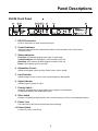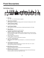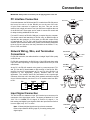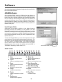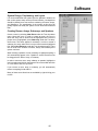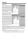
1
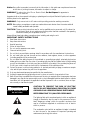
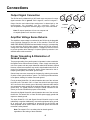
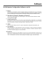
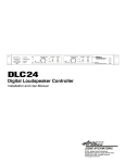
REMOTE CONTROL
FRONT CONTROL
ATTENUATION (dB)
OVERLOAD
12
HEARTBEAT
POWER
POLARITY
LIMIT
A CHANNEL
0
o
SIGNAL
60
0
LIMIT
180
100 Hz
B CHANNEL
0
o
FILTER
FLAT
3
32
o
POLARITY
6
FLAT
3
32
ATTENUATION (dB)
FILTER
12
6
COMMUNICATIONS
SIGNAL
60
RS-232
0
o
180
100 Hz
DLC24
DIGITAL LOUDSPEAKER CONTROLLER
POWER
DLC24
Digital Loudspeaker Controller
Installation and Use Manual
© 2004 Apogee Sound International
Specifications subject to change without notice.
55-0067-01D 0710 All rights reserved.
www.apogee-sound.com
Notice: Every effort was made to ensure that the information in this guide was complete and accurate
at the time of printing. However, information is subject to change.
WARNING: To reduce the risk of Fire or Electric Shock, Do Not Expose this apparatus to
rain or moisture.
Apparatus shall not be exposed to dripping or splashing and no objects filled with liquids, such as vases
shall be placed on the apparatus.
WARNING: Only connect unit to AC mains outlet providing protective earthing connection.
NOTE: Mains plug or an appliance coupler are used as disconnect devices from the mains and shall
remain readily accessible and operable.
CAUTION: These servicing instructions are for use by qualified service personnel only. To reduce the
risk of electric shock, do not perform any servicing other than that contained in the operating
instructions unless you are qualified to do so.
Always follow these basic safety precautions when installing and using the unit:
IMPORTANT SAFETY INSTRUCTIONS
1. Read these instructions.
2. Keep these instructions.
3. Heed all warnings.
4. Follow all instructions.
5. Do not use this apparatus near water.
6. Clean unit with dry cloth.
7. Do not block any ventilation openings. Install in accordance with the manufacturer's instructions.
8. Do not install near any heat sources such as radiators, heat registers, stoves, or other apparatus
(including amplifiers) that produce heat.
9. Do not defeat the safety purpose of the polarized or grounding-type plug. A polarized plug has two
blades with one wider than the other. A grounding-type plug has two blades and a third grounding
prong. The wide blade, or the third prong, are provided for your safety. If the provided plug does not
fit into your outlet, consult an electrician for replacement of the obsolete outlet.
10. Protect the power cord from being walked on or pinched particularly at plugs, convenience receptacles, and the point where they exit from the apparatus.
11. Only use attachments/accessories specified by the manufacturer.
12. Unplug this apparatus during lightning storms or when not used for long periods of time.
13. Refer all servicing to qualified service personnel. Servicing is required when the apparatus has been
damaged in any way, such as power-supply cord or plug is damaged, liquid has been spilled or objects
have fallen into the apparatus, the apparatus has been exposed to rain or moisture, does not operate normally, or has been dropped.
CAUTION
RISK OF ELECTRIC SHOCK
DO NOT OPEN
CAUTION: TO PREVENT THE RISK OF ELECTRIC
SHOCK, DO NOT REMOVE ANY FRONT/BACK COVERS
OR PANELS. NO USER-SERVICEABLE PARTS INSIDE.
REFER SERVICING TO QUALIFIED PERSONNEL.
The lightning flash with arrowhead symbol, within an equilateral
triangle, is intended to alert the user to the presence of uninsulated "dangerous voltage" within the product's enclosure that
may be of sufficient magnitude to constitute a risk of electric
shock to persons.
The exclamation point within an equilateral triangle is intended
to alert the user to the presence of important operating and
maintenance (servicing) instructions.
Contents
Page
PRECAUTIONS & SAFETY NOTES ..............................................................................2-3
DESCRIPTION ..................................................................................................................4
DLC24 Description ..............................................................................................................4
Package Contents ................................................................................................................4
Care and Maintenance ........................................................................................................4
PANEL DESCRIPTIONS ................................................................................................5-6
DLC24 Front Panel ..............................................................................................................5
DLC24 Rear Panel ..............................................................................................................6
CONNECTIONS ..............................................................................................................7-8
PC Interface Connection ......................................................................................................7
Network Wiring, Wire, and Termination Connections ..........................................................7
Input Signal Connection ......................................................................................................7
Output Signal Connection ....................................................................................................8
Amplifier Voltage Sense Returns ........................................................................................8
Proper Grounding & Elimination of Ground Loops ..............................................................8
OPERATION..................................................................................................................9-10
Front Panel Controls and Indicators ....................................................................................9
Rear Panel Controls and Indicators ..................................................................................10
SOFTWARE ................................................................................................................11-19
DLC24 Software Introduction ............................................................................................11
DLC24 Speaker Configuration Software ..............................................................11
ADAM Software ....................................................................................................11
Software Setup & Updates ..................................................................................11
DLC24 Speaker Configuration Software ......................................................................12-13
ADAM Software ............................................................................................................14-19
User/Designer Mode ............................................................................................14
ADAM Toolbar ......................................................................................................14
System Design, Preplanning, and Layout ..........................................................15
Creating Rooms, Arrays, Subarrays, and Speakers ............................................15
System Example ..................................................................................................16
Speakers ..............................................................................................................17
Channel/Loudspeaker Status Information ..........................................................17
Gain Control ........................................................................................................18
Delay ....................................................................................................................18
Equalization ........................................................................................................18
Snapshots ............................................................................................................19
Resets ..................................................................................................................19
Network Control and Monitoring from Non-Apogee Software and Devices ........19
Hardware Preset ..................................................................................................19
APPLICATION SETUP & CONFIGURATION EXAMPLES........................................20-27
Application
Application
Application
Application
Setup
Setup
Setup
Setup
&
&
&
&
Configuration
Configuration
Configuration
Configuration
1:
2:
3:
4:
Mono Bi-Amp with AUX-Fed Subwoofer............20-21
Stereo Bi-Amp ..................................................22-23
Stereo Single Amp with Subwoofer ..................24-25
Stereo Tri-Amp with AUX-Fed Subwoofer ........26-27
SPECIFICATIONS ............................................................................................................28
LIMITED WARRANTY......................................................................................................29
Precautions &
Safety Notes
English
• To reduce the risk of electric shock, disconnect the AC main power cord
before installing audio cable. Reconnect the power cord only after making
all signal connections.
• Connect the unit only to a three-pole, three-wire grounding mains
receptacle. The receptacle must be connected to a fuse or circuit breaker.
Connection to any other type of receptacle poses a shock hazard and may
violate local electrical codes.
• Do not install the unit in wet or humid locations.
• Do not allow water or any foreign object to get inside the unit. Do
not put objects containing liquid on, or near the unit.
• To reduce the risk of overheating the unit, avoid exposing it to direct
sunlight. Do not install the unit near heat-emitting devices or appliances, such
as a room heater or stove.
• The unit contains potentially hazardous voltages. Do not attempt to
disassemble the unit. The unit contains no user-serviceable parts. Repairs
should be performed only by factory trained service personnel.
Francais
• Pour réduire le risque d’électrocution, débrancher la prise principale de
l’unité, avant d’installer le cable d’interface allant à l’audio. Rebrancher le bloc
d’alimentation après avoir effectué toutes les connections.
• Branchez l’unité dans une prise de courant avec 3 dérivations (deux
pôles et la terre). Cette prise doit être munie d’une protection adéquate
(fusible ou coupe-circuit). Le branchement dans tout autre genre de prise
pourrait entraîner un risque d’électrocution et peut constituer une infraction à la réglementation locale concernant les installations électriques.
• Ne pas installer l’unité dans un endroit où il y a de l’eau ou humidité excessive.
• Ne pas laisser de l’eau ou autres objects pénétrer dans l’unité. Ne pas
placer d’object contenant un liquide sur ou a proximité de l’appareil.
• Pour éviter une surchauffe de l’unité, conserver-la à l’abri du soleil.
Ne pas installer à proximité d’appareils dégageant de la chaleur tells que
radiateurs ou appareils de chauffage.
2
Precautions &
Safety Notes
(cont’d)
Deutsch
• Um die Gefahr eines elektrischen Schlages auf ein Minimum zu reduzieren,
den Lautsprecher Kontroller vom Stromnetz trennen, bevor ein
Audiosignalkabel angeschlossen wird. Das Netzkabel erst nach Herstellung
aller Signalverbindungen wieder einstecken.
• Den Kontroller an eine geerdete dreipolige Schuko-Netzsteckdose
anschließen. Die Steckdose muss mit einem geeigneten Überlastschutz
(Sicherung oder Leistungsschalter) verbunden sein. Der Anschluss an einen
anderen Steckdosentyp kann zu Stromschlägen führen und gegen die
örtlichen Vorschriften für Elektrotechnik verstoßen.
• Den Kontroller nicht an einem Ort aufstellen, an dem er mit Wasser oder
mit übermäßig hoher Luftfeuchtigkeit in Berührung kommen könnte.
• Darauf achten, dass weder Wasser noch Fremdkörper in das Innere des
Kontroller eindringen. Keine Objekte, die Flüssigkeit enthalten, auf oder
neben den Kontroller stellen.
• Um ein Überhitzen des Kontroller zu verhindern, das Gerät vor direkter
Sonneneinstrahlung schützen und nicht in der Nähe von Wärme abstrahlenden Haushaltsgeräten (z.B. Heizgerät oder Herd) aufstellen.
• Im Inneren dieses Kontroller herrschen potentiell gefährliche Spannungen.
Nicht versuchen, das Gerät zu öffnen. Es enthält keine vom Benutzer zu
reparierenden Teile. Reparaturen dürfen nur von ausgebildetem
Kundendienstpersonal durchgeführt werden.
Español
• Para reducir el riesgo de descarga eléctrica, desconecte de la red el altoparlante antes de instalar el cable de señalización de interfaz de la segnale.
Vuelva a conectar el conductor flexible de alimentación solamente una vez
efectuadas todas las interconexiones de señalizatción.
• Conecte la unidad a un tomacorriente bipolar y trifilar con neutro de
puesta a tierra. El tomacorriente debe estar conectado a la protección de
derivación apropiada (ya sea un fusible o un disyuntor). La conexión a
cualquier otro tipo de tomacorriente puede constituir peligro de descarga
eléctrica y violar los códigos eléctricos locales.
• No instale la unidad en lugares donde haya agua o humedad excesiva.
• No deje que en la unidad entre agua ni ningún objeto extraño. No
ponga objetos con líquidos encima de la unidad ni cerca de ella.
• Para reducir el riesgo de sobrecalentamiento, no exponga la unidad a los
rayos directos del sol ni la instale cerca de artefactos que emiten calor,
como estufas o cocinas.
• Esta unidad contiene niveles de voltaje peligrosos en potencia. No
intente desarmar la unidad, pues no contiene piezas que puedan ser repardas por el usuario. Las reparaciones deben efectuarse únicamente por parte
del personal de mantenimiento capacitado en la fábrica.
3
Description
DLC24 Description
The DLC24 is a loudspeaker controller designed to provide the key elements that help ensure optimal loudspeaker
system performance and management in a variety of live sound and fixed installation applications.
The DLC24 is intended to be the last device in the signal chain before the power amplifier(s). It is usually fed signal from
a mixing console, although the source may be one of a number of devices such as a tape player, CD player,
or equalizer.
The DLC24 is a two-input, four-output controller that can be configured for any combination of Apogee speaker types
using proprietary software included with the unit.
Once configured, the DLC24 recalls all loudspeaker parameters on power up, no additional programming required. When
set to Front Control, it operates like a classic analog loudspeaker controller with local level control, polarity control, and
filter control, as well as signal, limit, and overload indicators.
With the addition of Apogee Digital Audio Management (ADAM) software and a PC, the user gains remote access to all
front panel controls, 12 bands of parametric equalization (per channel), over 1356 milliseconds of delay (per channel),
snapshots, a wide assortment of speaker status information plus system design capabilities (rooms, arrays, subarrays, etc.).
The DLC24 can accept either analog or digital input signal and can be networked with other DLC24's. The DLC24 and
Apogee’s APL-DSP powered loudspeakers can operate simultaneously on the same network. The DLC24 is also
designed to be compatible with other control systems.
Package Contents
DLC24 Loudspeaker Controller
Installation and Use Manual
IEC Line Cord
(2)Two Pluggable Screw Terminal Blocks
(2) Two Model Designation Label Sheets
Care and Maintenance
The plastic lens of the DLC24 employs light plate technology. Heavy oily residue, fingerprints, or scratches can allow
light to escape from the plastic lens. To clean the DLC24, first unplug the unit and then gently wipe it with a soft
cloth or facial tissue lightly dampened with water and/or a mild cleanser. Never use a paper towel since it may
scratch the acrylic lens.
The DLC24’s lens can be safely marked with China marker pencils. The writing will illuminate because of the light
plate technology. The writing can be removed by gently wiping with a dry facial tissue. The rest of the DLC24 unit can
be cleaned using a mild soap and a soft cloth.
After cleaning, make sure the DLC24 has dried completely before reconnecting it to the AC mains. All other maintenance
should be referred to qualified service personnel.
4
Panel Descriptions
DLC24 Front Panel
1
2 3
4 5 6 7
9
8
10
1. RS-232 Connection
Local PC Connection is made via this RS-232 port.
2. Control Indicators
Indicates whether the DLC24 Control Selector Switch on the rear panel is set to Front Control
or Remote Control.
3. Status Indicators:
Overload- LED indicates clipping at any input or output stage.
Communications- LED indicates PC communication on the unit.
Heartbeat- LED indicates the DSP hardware condition of the unit.
Power- LED indicates power to the DSP.
4. Attenuation Control
Adjusts the assigned output’s level(s). Range is from 0 dB to -60 dB.
5. Limit Indicator
Indicates limiting on one or more of the outputs assigned to that channel.
6. Signal Indicator
Indicates signal is present on input.
7. Polarity Switch
Inverts the assigned output’s signal polarity from 0 degrees to 180 degrees.
Configuration software can disable this function.
8. Filter Switch
Provides a 24 dB/octave high-pass filter, with a corner frequency at 100 Hz, to the assigned output(s).
9. Plastic Lens
The plastic lens of the DLC24 employs light plate technology.
10. Power Switch
Controls AC power to the DLC24.
5
Panel Descriptions
DLC24 Rear Panel
1
2
3
4 5
6
7
8
9
10
1. IEC Inlet
100 – 240V, 1.1A, 50-60 Hz AC power receptacle.
2. Signal Ground Switch
Select whether the DLC24’s power supply ground is connected to chassis ground or “lifted”.
3. Control Selector Switch
Select Front or Remote Control.
4. Input Selector Switch
Select whether the DLC24 accepts analog or digital signals through the XLR inputs.
5. Reset Button
Recessed button offers both a soft and hard reset.
6. Amplifier Sense Returns Barrier Strip
Monitors the amplifier’s output voltages in order to engage protective limiters necessary
to prevent damage to speakers. The connections are labeled 1 through 4 and correspond
to the XLR outputs.
7. Output Signal Connections
Four balanced 3-pin XLR male signal output connectors.
8. Input Pin 1 Shield Switch
Select whether “IN 1” and “IN 2” Input’s Shield (Pin 1) is connected to chassis ground
or “lifted”.
9. Input Signal Connections
Two balanced 3-pin XLR female signal input connectors. Note: Only “IN 1” is active
when Input Selector Switch is set to Digital.
10. RS-422 Input Connection
Remote PC connection is made via this 5-pin XLR female RS-422 port.
11. RS-422 Loop Connection
DLC24/PC network connection can be paralleled via this 5-pin XLR male RS-422 port,
making it possible to daisy-chain multiple DLC24 units.
6
11
Connections
IMPORTANT: Always make connections prior to applying power to the unit.
PC Interface Connection
Pin 3: RX
Pin 5: Ground
Pin 2: TX
Connection between the DLC24 and the PC is made via an RS-232 port on
the front of the unit or via the RS-422 port on the rear of the unit.
A 9-pin D-sub connector is located on the front. This port can be
used for local, single unit control. Two 5-pin XLR’s are located on the rear
of the DLC24 unit. These ports can be used for remote PC control and
for daisy-chaining additional DLC24 units.
For local PC control, an RS-232 COM port is required from the computer.
For remote control and networking of DLC24 units, an RS-422 output is
required from the computer. In most cases, the RS-422 output will be
on a terminal strip. TX+, TX-, RX+, and RX- will be used as well as ground if
available. Some interfaces allow some general communication parameters
to be set. If that is the case, then they should be set as follows: TX on,
RX on, DCE, and SIMU.
1 SH
2 TX3 TX+
4 RX5 RX+
RESET
Network Wiring, Wire, and Termination
Connections
SH
XLR 12Female
TX-
3 TX+
4 RX-
Pin 5: RX+
INPUT
5 RX+
For RS-232 connection, the cable should be a “straight” 9-pin D-Sub (male)
on DLC24 end.
Pin 1: Shield
ANALOG
Pin 4: RX-
Pin 2: TXPin 3: TX+
For RS-422 communication, the DLC24 has a 5-pin XLR female input and a
5-pin XLR male loop-through. Loop-through cables should be 5-pin XLR
male/female.
RESET
At the PC, the RS-422 network wires must be cross-connected. TX+
and TX- from the PC should attach to RX+ and RX- of the DLC24. RX+
and RX- from the PC should attach to TX+ and TX- of INPUT
the DLC24. It is
important to use high-quality, properly shielded cable for this
ANALOG
application. The network should be terminated at the loop-through
connector of the last unit in the chain. Basic network termination consists
RESET
of two 120-ohm resistors, one from TX+ to TX- and the other
from RX+
to RX-.
DLC24 DIGITAL
DLC24
PC
+TX
-TX
+RX
-RX
+RX
-RX
+TX
-TX
+RX
-RX
+TX
-TX
INPUT
CONTROL
ANALOG
SH
DIGITAL
XLR 12Male
TX-
3 TX+
4 RXPin 1: Shield
Pin 5: RX+
5 RX+
CONTROL
Pin 2: TXFRONT
Pin 4: RXPin 3: TX+
1 SH
2 TX3 TX+
4 RX5 RX+
1 SH
2 TX3 TX+
4 RX5 RX+
REMOTE
1 SH
2 TX3 TX+
4
From/To
5
DLC24
From
RESET
PC
RXRX+
From/To
DLC24
FRONT
INPUT
Input Signal Connection
ANALOG
DIGITAL
1 SH
2 TX-
The DLC24 has two balanced 3-pin XLR female input
connectors forRESET 3 TX+
REMOTE
4 RX5 RX+
connection of the signal input source. The inputs are labeled “IN 1” and
CONTROL
“IN 2”. Pin 1 is “shield”, Pin 2 is signal “+”, and Pin 3 is signal “- ”, for DIGITAL
both analog and digital inputs signals. When the InputFRONT
Selector Switch
is set to digital, only “IN 1” is active.
CONTROLXLR Female
1 SH
2 TX3 TX+
4 RX5 RX+
INPUT
FRONT
Note: 2 Channel digital signals are input via one connector.
RESET
REMOTE
analog
and ANALOG
Refer to Input Selector Switch (page 10) for setting
digital inputs.
Pin 3: –
ANALOG
Pin 1: Shield
Pin 2: +
REMOTE
7 INPUT
1 SH
2 TX3 TX+
4 RX5 RX+
1 SH
2 TX3 TX+
4 RX5 RX+
1 SH
2 TX3 TX+
4 RX5 RX+
1 SH
2 TX-
1 SH
2 TX-
1 SH
2 TX3 TX+
4 RX5 RX+
RESET
INPUT
Connections
ANALOG
Output Signal Connection
OUT 1
OUT 2
OUT 3
OUT 4
DIGITAL
The DLC24 has four balanced 3-pin XLR male output connectors for output
signal connection. Pin1 is “ground”, Pin 2 is signal “+”, and Pin 3 is signal “- ”.
CONTROL
Output function and channel/input assignment is determined
FRONTby the
configuration file uploaded into the controller. Refer to:
DLC24 Speaker Configuration Software (page 12) for more information.
XLR Male
Pin 3: –
Pin 1: Ground
Note: Bi-amped speakers will use two outputs and REMOTE
tri-amped speakers will use three outputs.
Amplifier Voltage Sense Returns
1
2
3
1
2
3
1
2
3
4
AMP SENSE RETURNS
Pin 2: +
1 SH
2 TX3 TX+
4 RX5 RX+
1 SH
2 TX3 TX+
4 RX5 RX+
1 SH
2 TX3 TX+
4 RX5 RX+
The amplifier’s output voltage is monitored by the DLC24 via the pluggable
screw terminals mounted on the rear of the controller. These are the
AMPLIFIER SENSE RETURNS and are labeled 1 through 4, corresponding
to the respective DLC24 signal outputs. When the DLC24 senses a
voltage that could damage the speaker, it engages protective limiters
to prevent speaker driver damage. Complete speaker protection is not
available without this connection.
RESET
1 SH
2 TX3 TX+
INPUT45 RXRX+
ANALOG
DIGITAL
1 SH
2 TX3 TX+
4 RX5 RX+
RESET
Proper Grounding & Elimination of
Ground Loops
The proper grounding of any audio system is important in order to maximize
the signal-to-noise ratio and ensure safety. Often, simply connecting the
unit to the system with the proper balanced cables will be all that is required.
However, certain interconnections may result in objectionable levels of hum at
power line fundamental frequencies and/or related harmonics due to
multiple ground paths, often called “ground loops”.
Ground loops can most commonly be eliminated by reducing the number
of paths to earth ground within a system. The DLC24 provides switches
in two places, allowing for isolation from earth ground.
First is the Input Shield Pin 1 lift switch located at the rear of the unit near
the XLR inputs. This switch “lifts” or “floats” the shield of both signal input
XLR connectors from chassis ground. Normally, balanced cable shields
are connected to earth ground via the equipment at both ends. In case of a
ground loop, it is typical practice to keep the shield connected at the
source (so as not to defeat the purpose of the shield).
Second is the Signal Ground lift switch located at the rear of the unit near
the AC inlet. This switch “lifts” or “floats” DLC24’s power supply ground with
respect to chassis ground.
The Input Shield Pin 1 lift and Signal Ground lift switch may be used
individually or together. Additionally, most audio equipment has a ground
lift of some type. Any combination of ground lifts on the DLC24 and
other equipment can be used to reduce or eliminate ground hum and will
not create a safety hazard.
Note: The output’s Pin 1 are always tied to chassis ground
regardless of the setting of these switches.
8
CONTROL
FRONT
INPUT
ANALOG
REMOTE
DIGITALRESET
1 SH
2 TX3 TX+
4 RX5 RX+
1 SH
2 TX3 TX+
4 RX5 RX+
CONTROL
FRONT
INPUT
ANALOG
REMOTE
DIGITAL
1 SH
2 TX3 TX+
4 RX5 RX+
1 SH
2 TX3 TX+
4 RX5 RX+
CONTROL
FRONT
REMOTE
1 SH
2 TX3 TX+
4 RX5 RX+
1 SH
2 TX3 TX+
4 RX5 RX+
Operation
Front Panel Controls and Indicators
Remote Control Indicator
This LED will illuminate green when the DLC24’s Control Selector Switch
is in the Remote position. Front panel controls are disabled and only PC
control is available.
Front Control Indicator
This LED will illuminate green when the DLC24’s Control Selector Switch
is in the Front position. Front panel functions are enabled. Associated
controls in the ADAM software are disabled.
Overload Indicator
This LED will illuminate red when clipping is present at any of the input
or output stages.
Communications Indicator
This LED will illuminate green when communication is present between
the DLC24 and a PC.
Heartbeat Indicator
Indicates the status of the internal DSP. If operating normally, this LED
will blink ON for 100 ms every second. If there is any type of hardware
problem, this LED interval will be ON for 250 ms and OFF for 250 ms.
Power Indicator
This LED lights green to confirm power to the DSP.
Attenuation Control
Controls the amount of signal attenuated to the channel’s assigned
output(s), ranging from 0 dB to 60 dB.
Limit Indicator
This LED will illuminate amber when there is any limiting associated
with that channel.
Signal Indicator
This LED will illuminate green when any signal is present at the input.
Polarity Switch
Inverts the signal’s polarity (0° to 180°) of the output(s) assigned to
the channel. This function must be “Enabled” in DLC24 Speaker
Configuration Software in order for this switch to operate.
Filter Switch
Provides a 24 dB/octave high-pass filter with a corner frequency at
100 Hz to the output(s) assigned to the channel. Speaker type can
affect this function. Subwoofers, for example, cannot be high-passed.
9
FRONT
REMOTE
Operation
1 SH
2 TX3 TX+
4 RX5 RX+
1 SH
2 TX3 TX+
4 RX5 RX+
1 SH
2 TX3 TX+
4 RX5 RX+
Rear Panel Controls and Indicators
Signal Ground Switch
RESET
This switch “lifts” or “floats” the DLC24’s power supply ground from
chassis ground. Placing the switch in the “lift” position may help to
minimize system hum or buzz caused by ground loops. Refer to Proper
Grounding & Elimination of Ground Loops (page 8) for more information.
INPUT
1 SH
2 TX3 TX+
4 RX5 RX+
ANALOG
DIGITAL
Control Selector Switch
1 SH
2 TX3 TX+
4 RX5 RX+
CONTROL
RESET
When this switch is set to “Front”, the DLC24’s front panel controls are
active and any associated software controls are inhibited. When the Control
Selector Switch is set to “Remote”, the software controls are active and the
DLC24’s front panel controls are inhibited.
FRONT
INPUT
ANALOG
REMOTE
RESET
DIGITAL
Input Selector Switch
This switch determines whether the DLC24’s signal inputs will accept
analog or digital signals. If the switch is set to digital, only the “IN 1”
connector will be active. Refer to Input Signal Connection (page 7) for
more information.
1 SH
2 TX3 TX+
4 RX5 RX+
1 SH
2 TX3 TX+
4 RX5 RX+
INPUT
ANALOG
CONTROL
1 SH
2 TX3 TX+
4 RX5 RX+
FRONT
DIGITAL
REMOTE
CONTROL
FRONT
Reset Button
This recessed button offers both a soft and hard reset. If pressed in for
one second, it will reset the controller without changing any settings.
If pressed in and held for 3 seconds or more, it will reset the controller
to factory defaults (all EQ, all Gain, and all Delays will be reset to “0”).
RESET
1 SH
2 TX3 TX+
4 RX5 RX+
1 SH
2 TX3 TX+
4 RX5 RX+
REMOTE
INPUT
ANALOG
1 SH
2 TX3 TX+
4 RX5 RX+
1 SH
2 TX3 TX+
4 RX5 RX+
Input Pin 1 Shield Switch
This switch “lifts” or “floats” the Pin 1 shield connection from chassis
ground on both signal input XLR connectors. Place the switch in the “lift”
position in order to minimize system hum or buzz caused by ground
loops. Refer to Proper Grounding & Elimination of Ground Loops (page 8)
for more information.
DIGITAL
CONTROL
FRONT
REMOTE
1 SH
2 TX3 TX+
4 RX5 RX+
10
1 SH
2 TX3 TX+
4 RX5 RX+
Software
DLC24 Software Introduction
Updates to the DLC24 Speaker Configuration Software, ADAM software, and firmware may be downloaded from the
Apogee web site at www.apogee-sound.com/software.
Two software programs are needed for the DLC24. (1) The DLC24 Speaker Configuration Software, which enables the
user to custom configure the DLC24 for use with any Apogee speaker type and (2) ADAM Software, which provides remote
operational control and monitoring of the speaker system through a PC.
Note: Only one software program may be opened at a time.
DLC24 Speaker Configuration Software
The DLC24 Speaker Configuration Software enables the user to custom configure the DLC24 for use with any
Apogee speaker type. The DLC24 Speaker Configuration Software enables the user to select Apogee speaker types,
enable or disable the Polarity switch, select channels, and select inputs for each of the four outputs. Also, the user can
add channel descriptions for reference purposes in ADAM.
ADAM Software
The ADAM Software provides control and monitoring of the DLC24 through a PC, allowing the use of a wide variety of
features that would otherwise be unavailable to the user.
Note: In order to obtain full control via the ADAM software, the Control switch on the back of the unit
must be set to the “Remote” position. If set to “Remote”, the front panel controls are disabled.
Software Setup & Updates
Download the latest version of the DLC24 Speaker Configuration Software and ADAM Software from the Apogee
Sound International website, at www.apogeesound.com/software/. Click on “ADAM & DLC24 Speaker Configuration
Software” in the table. A Terms & Conditions window will pop up. After reading the agreement, click “ACCEPT”. The
software will begin to download to your computer. (Depending on your computer settings, you may need to manually
start the download to begin.) You may need to select the directory as to where you intend to save the file.
To run the software, open the directory to where you saved the file, highlight and click on the ADAM setup file. The program will automatically open to the installation setup.
A welcome dialog box will appear. Click “Next”. A new dialog box will appear. Enter a “User Name” and an
“Organization” and check off one of the two user choices at the bottom of the dialog box (all users or single user) and
then click “Next.”
The next dialog box will ask about a
destination folder for the software. It is
recommended that all default folders be
used when installing the software. If a
different installation folder is desired,
click on “Change”. Otherwise, click on
“Next”. In the next dialog box, click
“Install”. After the software has been
installed, click “Finish”. Updates to the
software and firmware can be found on
the Apogee web site at www.apogeesound.com.
11
Software
DLC24 Speaker Configuration Software
3
4
5
1
2
6
7
8
9
10
1. Outputs
Apogee speaker types are selected from the drop-down menu next to each output. An AE5 has been
selected for Output 1 in the example shown. Since the AE5 is a bi-amped speaker it requires two
outputs. As a result, Output 2 has been automatically selected with Output 1 representing the high
frequency (HF) of the AE5; and Output 2, the low frequency (LF) of the AE5. An AESB has been selected for
both Output 3 and Output 4 in the example.
2. Polarity
Polarity may be enabled or disabled. When enabled, the Polarity Switch on the front panel of the DLC24
is active as is the Polarity box in ADAM. When disabled, neither the front panel switch on the DLC24
nor the Polarity box in ADAM are operable. When a subwoofer is selected, such as the AESB, “Enable”
is automatically selected, though it can be deselected. In the example, both AESB’s are enabled
whereas the AE5 is disabled. When bi-amped or tri-amped speakers are chosen, the polarity setting for all
associated outputs will change when the active button is changed.
3. Channel Membership
Channel Membership is selected on an individual speaker basis. When a speaker requires multiple
outputs, whatever channel is selected for the first output will automatically be selected for any additional
outputs reserved for that speaker. For example, with an AE5, if “Ch A” is selected for the high
frequency (HF), “Ch A” will automatically be selected for the low frequency (LF).
4. Input Selection
Input Selection is determined on an individual speaker basis. When a speaker requires multiple outputs,
whatever input is selected for the first output will automatically be selected for any additional outputs
reserved for that speaker. In addition, when “Ch A” is selected, “In 1” is automatically selected.
Same for “Ch B” and “In 2”. However, this auto selection can be overridden. Input 1 and Input 2
“(In 1 + In 2) / 2” can also be selected for an output, such as for subwoofers requiring a mono-summed
stereo input.
12
Software
DLC24 Speaker Configuration Software (cont’d)
5. Browse
Directories may be browsed to search for Apogee speaker type configuration files (.cfg). Configuration
files for all Apogee speaker types will automatically download during the software installation to a default
directory recognized by the DLC24 Speaker Configuration Software during the installation process.
6. Description of Channel A / Description of Channel B
This is the user-defined default name that will appear in the Channel and Status Windows in ADAM.
It can be renamed in ADAM.
7. Create Download File
By selecting this button, the user can save the user-created speaker configuration to a configuration
download file (.cdl). This file will be used to download the speaker configuration to the DLC24. If the file
is saved successfully, a dialog box will appear saying, “Download file created!”
8. COM 1
Select the proper COM port of the PC in order to download the configuration download file (.cdl).
9. Scan Network
Select Scan Network to search and detect any units on the network. In order for a DLC24 to be detected,
it must be properly connected to a PC using either an RS-232 or RS-422 connection. Refer to
PC Interface Connection (page 7) for more information.
10. Download
Once a unit is detected using Scan Network, select the unit and press Download. A dialog box will
appear asking, “Downloading will replace the existing configuration. Do you wish to proceed?” Press
“Yes”. If the download is successful, another dialog box will appear saying, “Download finished.”
13
Software
After having downloaded the Speaker Configuration file to the DLC24,
launch the ADAM software.
ADAM Software
After launching ADAM, select the COM port for the software to
access the unit or network. If there are multiple COM ports for different zones, all the relevant COM ports may be selected by holding
down the CTRL key while selecting the COM ports. The software will
combine the information from all active COM ports and display the
speakers within the software as one large network. It is not necessary to switch between networks to control or monitor speakers on
different COM ports.
User/Designer Mode
ADAM starts in User Mode by default. In User Mode all network
monitoring functions are available, but only Master Level and
Master Mute controls are active. In Designer Mode, the user retains
all network monitoring functions while also gaining the ability to create
and control an entire system in ADAM. Designer Mode allows the
user to access features such as gain, delay, equalization, loudspeaker status, etc.
To enter into Designer Mode, go to the View drop-down menu and
select Designer. Enter the factory default password “designer”. The
password is not case sensitive and may be changed at any time.
The user must be in Designer Mode for the Change Password
option to become active in the View drop-down menu. In the lower
right-hand corner of the window, the software will read “USER” or
“DESIGNER” depending on what mode it is in.
MODE INDICATOR
ADAM Toolbar
1
2
3
4
5
6
1. New
Creates a new document.
2. Open
Opens an existing document.
3. Save
Saves the active document.
4. Remove
Removes a selected item.
5. Copy
Copies a selected item.
6. Paste
Pastes a removed or copied
item.
7
8
9
10
11
12
13
8. Move Up
Moves a selected item up.
9. Move Down
Moves a selected item down.
10. Sort Ascending
Sorts in ascending order.
11. Sort Descending
Sorts in descending order.
12. Print
Prints the active document.
13. Tool Tips
Enables tool tips.
7. Rediscover
Rediscovers all speakers.
14
Software
System Design, Preplanning, and Layout
It is recommended that the system layout be planned in advance so
that on-site system setup can be quick and effective. Loudspeakers
should be placed into a tree structure consisting of Rooms, Arrays,
and Subarrays. The organization of the system at this point will
greatly impact how easily the system can be tuned and controlled
later.
Creating Rooms, Arrays, Subarrays, and Speakers
Create a room by selecting New Room under the Tree drop-down
menu. Name the room. In order to create an array, the room in
which the array can be found must be highlighted first. Once the
proper room is highlighted, select New Array under the Tree dropdown menu. The same applies for subarrays. In order to create a
subarray, the array under which it can be found must be highlighted
first. Select New Subarray under the Tree drop-down menu. There
are no limits to the number of Rooms, Arrays, and Subarrays the
system can have.
When creating a speaker it is not necessary to highlight anything. It
will automatically appear in the “Speakers” section and then must
be dragged to the Room, Array, or Subarray.
In order to remove a room, array, subarray, or speaker, highlight the
item in question and click on the scissors icon on the toolbar and click
on “Yes” when it asks “Are you sure?
If you remove a room, array, or subarray, you will automatically
remove everything found within it.
Many of these same functions are available by right-clicking your
mouse.
15
Software
System Example
This system example is provided to efficiently
outline how to utilize the system structure of
ADAM. It is provided in this manual as a
teaching tool and does not exist as a tutorial in
the software. It includes a center cluster of
two speakers in a horizontal array along with
one subwoofer and four front fill speakers
mounted at the stage lip. At this point in time
the speakers should be wired up and on, the
software loaded and running in Designer
mode, and all the loudspeakers in the network
should have been discovered.
Begin by creating a room and naming it “Main
Hall”. Next, highlight the newly created room
and create an Array and name it “CTR Cluster”.
Repeat this process and create a second array
under the Main Hall and name it “Front Fill”.
For the purpose of this example, seven generic
speakers are shown to represent the center
cluster, subwoofer, and four front fill speakers.
Next, select and drag speakers into the newly
created room structure. Drag the two center
cluster speakers into the array labeled “CTR
Cluster”. Drag the four front fill speakers into
the array labeled “Front Fill”. Drag the subwoofer into the room labeled “Main Hall”. If
you select the “Main Hall” from the speaker
groupings menu, you will see the Room master
channel, a channel for each array, and the
panel for the subwoofer on the room level.
If you select the “CTR Cluster” from the speaker groupings window, you will see the array
master channel as well as the two speaker
panels that make up the array.
If a controller is not connected properly or is
not powered up, a red “X” will appear next to
any speaker associated with that controller.
When the controller is connected properly and is powered up, a green dot will appear next to each speaker associated with that controller. When a speaker is not operating in a normal manner (e.g., experiencing a clipping condition),
a red dot will appear next to the room, the array, and the subarray that the speaker is located in, as well as next to
the speaker itself.
Save the system using the “Save As” command from the File drop-down menu. Each time the software is
launched from the start menu, it will start with a new unconfigured network.
Note: If a padlock icon appears in the channel/loudspeaker panel window, then the Control Selector
Switch is in the “Front” position. To remove the lock, switch the Control Selector Switch to “Remote”.
16
Software
Speakers
After launching ADAM, the software will automatically discover speakers on the network. Each speaker will be listed in
tree format by its ID # and speaker configuration description on the left-hand side of the screen (“Speakers” section).
Double clicking on any speaker will bring up a panel to the right showing the general information of the speaker selected.
Do not adjust any parameters at this time. Wait until the system has been laid out in the software before proceeding with
any adjustments.
Note: Settings can be lost when moving speakers from the main tree to the appropriate room or array.
If more speakers are added to the network, go to the Tree drop-down menu and select “Discover New Speakers” to make
them available. To add a speaker, go to the Tree drop-down menu and select “New Speaker” and then give it a name.
Channel/Loudspeaker Status Information
A great deal of real time information is available from each channel/loudspeaker panel. To access
this data, double-click a channel/loudspeaker. A new panel will appear showing the current status of the
channel/loudspeaker. Clicking on any of the indicators or “Status” button, the channel/loudspeaker panel will
bring up the status window. The information available on the channel/loudspeaker panel is outlined below:
Online – Illuminates green when DLC24 is online
Signal – Illuminates green when input signal is present.
Clip – Illuminates red when clipping is present.
Limit – Illuminates red when the limiter engages.
Flat – High pass filter. Enabled when depressed (red). High pass filter
is not available for high frequency outputs.
Channel
Status Window
Polarity – Output signal polarity is inverted by 180 degrees when depressed (red).
Mute – Output signal mutes when depressed (red).
The information available on the “Status” window is outlined below:
Firmware Version – Indicates the microcontroller firmware version.
DSP Version – Indicates the DSP firmware version.
Input Clip – This illuminates red when the input clips.
DSP Online – This illuminates green when the DLC24 is powered
up and the DSP is functioning properly.
Out 3/Out 4 – Each output associated with the channel will be
shown with corresponding speaker type and passband.
Output Clip – This illuminates red when the output clips.
Peak Limit – This illuminates red when the peak limiter engages.
Power Limit – This illuminates red when the power limiter engages.
Polarity – Indicates if the Polarity feature is enabled or disabled.
Input – Indicates which input was selected for that output.
Loudspeaker Status Window
Displayed at the top of each channel status window is the channel description followed by the ID number of the controller
and the channel. It reads “AE1A-222A” at the top. The “AE1A” is the channel description given for Channel A, the “222”
is the ID number of the controller, and the “A” at the end is the channel.
Displayed at the top of each loudspeaker status window is the channel description followed by the channel and the ID
number of the controller. It reads “AE12-225B-Ch B, ID225” at the top. The “AE12” is the channel description given for
Channel B, the “225” is the ID number of the controller, and the “B” at the end is the channel
The channel description can be renamed at anytime when in Designer Mode by highlighting it in the “Speakers” window
and right-clicking on it or clicking on Tree and then Rename.
17
Software
Gain Control
Gain can be individually set for each channel or can be set for
groups of channels at one time. Gain can be adjusted by dragging the
fader or by entering data directly into the window labeled “Gain”.
Gain must be entered as a negative number.
In the example, both speakers have -6 dB of gain set by the master
channel. This gain also appears in each loudspeaker’s panel under
total gain. On Speaker 1, an additional -4 dB of gain has been added
so that the total of -10 dB is displayed in the total window.
Delay
Each channel is capable of 1356 ms of delay. Delay can be individually
set for each channel or can be set for groups of loudspeakers at one
time by entering the delay in the master channel for that group of
loudspeakers. In the example, all three speakers have 12 ms of delay
set by the master channel. The 12 ms of delay also appears in each
loudspeaker’s panel under total delay. On Speaker 5, an additional 3
ms of delay has been added so that the total delay of 15 ms is
displayed in the total window.
Note: The speed of sound is generally approximated to be
1130 feet/sec (344 meters/sec). To calculate delay from
a known distance, divide the distance by the speed of sound.
For example, 65 feet/1130 feet per second = 57.5 ms.
Equalization
Each channel contains 12 fully parametric filters. Each filter can be
a Bandpass, Highpass, Lowpass, Highshelf or Lowshelf filter.
To use the filters, first select the filter number you want to activate
or edit. In the example, #1 is selected. If the filter is available, select
“Filter Enabled”. It is now possible to select the type of filter
desired and adjust the associated parameters. The active filter will
be displayed in Red. If “Overall Response” is selected, a green
trace shows the response of all active filters being applied to that
channel. Once the filter is selected and enabled, it is also possible
to “mouse-click” in the graphical area in order to set the filter frequency
and gain.
18
Software
Snapshots
Gain, Delay, and EQ settings for a Room, Array, Subarray, or
Speaker are saved via Snapshots. Snapshots can be particularly
helpful for saving and recalling settings for different scenarios.
Snapshots are saved directly in the ADAM Software.
Resets
The ADAM software includes several levels of resets. Each reset
will return the settings of the entire system, room, array, or subarray,
depending on which reset is chosen, back to “0”.
Global Reset - Resets an entire system’s settings back to “0”.
Room Reset - Resets an entire room’s settings back to “0” including everything within the room (arrays, subarrays,
and speakers).
Array Reset - Resets an entire array’s settings back to “0” including everything within the array (subarrays and speakers).
Subarray Reset - Resets an entire subarray’s settings back to “0” including everything within the subarray (speakers).
Factory Default - Resets the speaker’s settings back to “0”.
Note: If there are higher level settings associated with any of the above resets, those settings will
still be maintained.
Network Control and Monitoring from Non-Apogee Software and Devices
If controlling the loudspeakers from a non-Apogee device or checking the system using Hyperterminal instead of
Apogee software, use the following parameters:
Baudrate 38400 • 8-bit • No parity • 1 stop-bit • No hardware handshaking
In ASCII setup:
Set Echo local character • Append linefeed to received data
When the unit is powered on, a line with this ID number, versions, and the name assigned to the loudspeaker should
be received. Each unit has a unique ID number. This will be used when communicating with that unit. In hyperterminal,
type the ID number followed by the character command and then press enter. The appropriate data will be returned or
action taken. Below is a partial list of commands that need to be preceded by the ID# of the unit and followed by the
Enter key. After the alpha command, “1” refers to Channel A and “2” refers to Channel B.
“ID#”VE<Enter> - Provides the firmware version number.
“ID#”SV2<Enter> - Returns the current volume (-6 dB) in multiples of 0.5 dB steps for “Ch B”.
“ID#”SV1,-6<Enter> - Sets the volume to -3 dB for “Ch A”. This is 6 steps.
“ID#”GM<Enter> - Returns the speaker model.
“ID#”SD2<Enter> - Returns the current speaker delay for “Ch B”.
“ID#”SD1,10<Enter> - Sets the delay to 10 ms for “Ch A”.
“ID#”MU1<Enter> - Returns if “Ch A” is muted.
“ID#”MU2,0<Enter> - Unmutes the output(s) for “Ch B”.
Hardware Preset
The hardware preset menu can be found under the View dropdown. The hardware preset allows the user to save the system’s
settings so that they can be loaded via a non-Apogee device.
Hardware presets, unlike software snapshots, are saved directly
to the DLC24’s hardware memory.
19
Application Setup 1
MONO BI-AMP
with AUX-FED SUBWOOFER
SOFTWARE
INTERFACE
MIXING
BOARD
(OPTIONAL)
RS-422
LEFT
or AUX 1
or RS-232
(Front)
AUX 2
AUX 2
L or AUX 1
AMPLIFIER SENSE RETURNS
DLC24
INPUT
SHIELD
(PIN 1)
(REAR)
AMPLIFIER
SENSE RETURNS
SUB2
HF
SUB1
LF
CH
A
CH
B
CHANNEL
A
VOLUME
CH
CHANNEL
B
PUSH
INPUT
VOLUME
PUSH
INPUT
A
CH
B
CHANNEL
A
VOLUME
Typical Stereo Power Amplifier
CHANNEL
B
PUSH
VOLUME
INPUT
PUSH
INPUT
Typical Stereo Power Amplifier
HF
SUB2
LF
SUB1
LOUDSPEAKERS
SUBWOOFER
(Apogee AE-5)
(Apogee AE12s2)
SUB2
SUB1
LF
20
Application Configuration 1
Mono Bi-Amp with Aux-Fed Subwoofer
Select an AE5 for Output 1. Since the AE5 is a bi-amped preset, DLC24 Speaker Configuration Software automatically
fills Output 1 for the high frequency (HF) and Output 2 for the low frequency (LF). Polarity, Channel Membership, and
Input Selection for Output 2 are automatically selected based on the selections for Output 1.
Enable “Polarity” if required. Select “Ch A” for the Channel Membership. Once “Ch A” is selected, “In 1” will automatically
be selected for the Input Selection.
Select an AE12s2 for Output 3. Polarity (by default) is always enabled for subwoofers. Since the subwoofers in this
application will be from a separate aux-feed, select “Ch B” for Channel Membership. Once “Ch B” is chosen, “In 2” will
automatically be selected for the Input Selection.
Repeat for Output 4.
Type a description for both Channel A and Channel B. This description will appear in ADAM at the top of the
channel/loudspeaker panel window and the loudspeaker status window. It can be changed later in ADAM.
21
Application Setup 2
STEREO BI-AMP
SOFTWARE
INTERFACE
MIXING
BOARD
(OPTIONAL)
RS-422
or RS-232
(Front)
RIGHT
LEFT
AMPLIFIER SENSE RETURNS
DLC24
INPUT
SHIELD
(PIN 1)
(REAR)
AMPLIFIER
SENSE RETURNS
HF
LF
LEFT
CH
A
CH
B
CHANNEL
A
VOLUME
CH
CHANNEL
B
PUSH
INPUT
VOLUME
RIGHT
HF
LF
PUSH
INPUT
A
CH
B
CHANNEL
A
VOLUME
Typical Stereo Power Amplifier
CHANNEL
B
PUSH
INPUT
VOLUME
PUSH
INPUT
Typical Stereo Power Amplifier
LF
HF
LF
HF
LOUDSPEAKERS
LOUDSPEAKERS
(Apogee AE-5)
(Apogee AE-5)
LF
LF
22
Application Configuration 2
Stereo Bi-Amp
Select an AE5 for Output 1. Since the AE5 is a bi-amped preset, DLC24 Speaker Configuration Software automatically
fills Output 1 for the high frequency (HF) and Output 2 for the low frequency (LF). Polarity, Channel Membership, and
Input Selection are automatically selected for Output 2 based on the selections for Output 1.
Enable “Polarity” if required. Select “Ch A” for the Channel Membership. Once “Ch A” is selected “In 1” will automatically
be selected for the Input Selection.
Select an AE5 for Output 3. Since the AE5 is a bi-amp preset, ADAM automatically fills Output 3 for the high frequency
(HF) and Output 4 for the low frequency (LF). Polarity, Channel Membership, and Input Selection are automatically
selected for Output 4 based on the selections for Output 3.
Enable “Polarity” if required. Select “Ch B” for the Channel Membership. Once “Ch B” is selected “In 2” will automatically
be selected for the Input Selection.
Type a description for both Channel A and Channel B. This description will appear in ADAM at the top of the
channel/loudspeaker panel window and the loudspeaker status window. It can be changed later in ADAM.
23
Application Setup 3
STEREO SINGLE AMP
with SUBWOOFER
RIGHT
MIXING
BOARD
SOFTWARE
INTERFACE
(OPTIONAL)
LEFT
RS232
DLC24 (FRONT)
REMOTE CONTROL
FRONT CONTROL
ATTENUATION (dB)
OVERLOAD
12
POLARITY
LIMIT
A CHANNEL
POWER
0
o
ATTENUATION (dB)
LIMIT
SIGNAL
60
180
100 Hz
0
B CHANNEL
0
FILTER
o
FLAT
3
32
o
POLARITY
6
FLAT
3
32
HEARTBEAT
FILTER
12
6
COMMUNICATIONS
SIGNAL
60
o
180
100 Hz
0
DLC24
DIGITAL LOUDSPEAKER CONTROLLER
RS-232
POWER
LEFT
RIGHT
IGHT
AMPLIFIER SENSE RETURNS
DLC24
INPUT
SHIELD
(PIN 1)
(REAR)
AMPLIFIER
SENSE RETURNS
LEFT
SUB
RIGHT
A
CH
CH
B
CHANNEL
A
VOLUME
CH
CHANNEL
PUSH
INPUT
B
VOLUME
PUSH
INPUT
A
CH
B
CHANNEL
A
VOLUME
Typical Stereo Power Amplifier
CHANNEL
PUSH
INPUT
B
VOLUME
PUSH
INPUT
Typical Stereo Power Amplifier
(Bridge Mode)
L
SUB
R
SUBWOOFER
COMPACT LOUDSPEAKERS
(Apogee AFI-118)
(Apogee SSM)
LEFT
SUB
RIGHT
24
Application Configuration 3
Stereo Single Amp with Subwoofer
Select an SSM for Output 1. Enable “Polarity” if required. Select “Ch A” for the Channel Membership. Once “Ch A” is
selected, “In 1” will automatically be selected for the Input Selection.
Select an SSM for Output 2. Enable “Polarity” if required. Select “Ch A” for the Channel Membership. “In 1” will
automatically be selected, although this can be overriden by selecting “In 2” in order to maintain true stereo operation.
Select an AFI-118 for Output 3. Polarity (by default) is always enabled for subwoofers. Select “Ch B” for Channel
Membership. “In 2” will automatically be selected, although this can be overriden by selecting “(In 1 + In 2) / 2” for
the Input Selection.
Type a description for both Channel A and Channel B. This description will appear in ADAM at the top of the
channel/loudspeaker panel window and the loudspeaker status window. It can be changed later in ADAM.
Note: SSM overall gain (left and right) will be controlled via “Ch A”. Left to right ratio will be controlled via the source. Subwoofer gain (left and right) will be controlled via “Ch B”.
25
Application Setup 4
STEREO TRI-AMP
with AUX-FED SUBWOOFER
MIXING
BOARD
LEFT
RIGHT
AUX
SOFTWARE
INTERFACE
(OPTIONAL)
RS422
RS422 Loop
AMPLIFIER SENSE RETURNS
AMPLIFIER SENSE RETURNS
DLC24
DLC24
INPUT
SHIELD
(PIN 1)
INPUT
SHIELD
(PIN 1)
(REAR)
(REAR)
SUB
SUB
AMPLIFIER
SENSE RETURNS
AMPLIFIER
SENSE RETURNS
LF
LF
MF
MF
HF
HF
CH
A
CH
B
CHANNEL
A
VOLUME
CH
CHANNEL
B
PUSH
INPUT
VOLUME
CH
B
CHANNEL
A
VOLUME
INPUT
Typical Stereo Power Amplifier
HF
A
PUSH
CHANNEL
INPUT
VOLUME
PUSH
INPUT
Typical Stereo Power Amplifier
HF
MF
MF
LF
LF
CH
A
CH
B
CHANNEL
A
VOLUME
CH
CHANNEL
B
PUSH
INPUT
VOLUME
A
CH
B
CHANNEL
A
PUSH
VOLUME
INPUT
Typical Stereo Power Amplifier
LF1
CHANNEL
B
PUSH
INPUT
VOLUME
PUSH
INPUT
Typical Stereo Power Amplifier
LF1
LF2
LF2
SUB
SUB
CH
A
CH
B
CHANNEL
A
VOLUME
CH
CHANNEL
PUSH
INPUT
B
VOLUME
CHANNEL
A
INPUT
B
VOLUME
PUSH
INPUT
SUBWOOFER
(Apogee AE12s2)
LF1
LF2
SUB 2
CHANNEL
PUSH
SUB2
MF
(Apogee AE12s2)
LF2
B
Typical Stereo Power Amplifier
SUB1
HF
SUBWOOFER
LF1
CH
VOLUME
INPUT
SUB2
MF
A
PUSH
Typical Stereo Power Amplifier
SUB1
HF
B
PUSH
SUB 2
SUB 1
SUB 1
TRI-AMP LOUDSPEAKER
TRI-AMP LOUDSPEAKER
(Apogee ALA 9)
(Apogee AL A 9)
LF1
LF1
LF2
LF2
26
NOTE: For Sub and LF Amps make sure both
amplifier channel gains are set equally.
Application Configuration 4
Stereo Tri-Amp with Aux-Fed Subwoofer
Select an ALA9 for Output 1. Since the ALA9 is a tri-amped preset, DLC24 Configuration Software automatically fills Output 1 with the high frequency (HF), Output 2 with the mid frequency (MF), and Output 3 with the low
frequency (LF). Polarity, Channel Membership, and Input Selection are automatically selected for Outputs 2 and 3
based on the selections for Output 1.
Enable “Polarity” if required. Select “Ch A” for the Channel Membership. Once “Ch A” is selected, “In 1” will automatically be selected for the Input Selection.
Select an AE12s2 for Output 4. “Polarity” is enabled by default. Select “Ch B” for the Channel Membership. Once
“Ch B” is selected, “In 2” will automatically be selected for the Input Selection.
Type a description for both Channel A and Channel B. This description will appear in ADAM at the top of the
channel/loudspeaker panel window and the loudspeaker status window. It can be changed later in ADAM.
27
Specifications
Inputs Analog
Number of Inputs:
Connectors:
Type:
Impedance:
Max. Input Line Level:
CMRR:
(2)
3-pin Female XLR
Electronically balanced
25k ohm
+15 dBu
> 85 dBu
Inputs Digital
Number of Inputs:
Connectors:
Type:
(1)
3-pin Female XLR
AES-EBU
Outputs Analog
Number of Outputs:
Connectors:
Type:
Impedance:
Max. Output Level:
(4)
3-pin Male XLR
Electronically balanced
100 ohm
+15 dBu
PC Interface
RS232:
RS422:
9-pin D-Sub, front panel
5-pin Female XLR Input, rear panel
5-pin Male XLR Loop, rear panel
Min. PC System Requirements
Operating System:
Processor:
Memory:
Windows® 2000 or XP
200 MHz Pentium III
128 MB RAM
System Performance
Frequency Response:
Dynamic Range:
Noise:
THD+N:
Max. Delay:
Filters:
Limiters:
20 Hz – 20 kHz, +/- 0.5 dB
> 100 dBu
> 90 dBu
< 0.009%, 20 Hz – 20 kHz
1356 ms
12 Band per channel
Proprietary, tri-stage Multi-band
Power
Input AC:
Connector:
100 - 240V AC, 1.1A, 50 - 60 Hz
3-pin IEC
Physical
Product Weight:
Dimensions:
10 lb. (4.536 kg.)
19" W x 1 3⁄4" H x 11" D
(482.6 mm W x 44.45 mm H x 279.4 mm D)
28
Warranty
LIMITED WARRANTY
Apogee Sound International's DLC24 is warranted to be free from defects in materials and workmanship, under normal
use and service, when installed and operated in accordance with product specifications, from the date of original
purchase for a period of three (3) years.
If any part of the equipment covered by this warranty malfunctions, it will be repaired or replaced, at our option, provided
the equipment is shipped prepaid to an authorized Apogee Service Facility.
This warranty does not extend to finish; appearance items; or any product malfunctions due to abuse, accident, misuse,
negligence, misapplication or operation under other than specified conditions, or if altered in any way.
THIS LIMITED WARRANTY IS OUR SOLE AND EXCLUSIVE WARRANTY AND THE PURCHASER'S SOLE AND EXCLUSIVE
REMEDY. APOGEE SOUND INTERNATIONAL MAKES NO OTHER WARRANTIES OF ANY KIND, EXPRESS OR IMPLIED,
AND ALL IMPLIED WARRANTIES OF MERCHANTABILITY AND FITNESS FOR A PARTICULAR PURPOSE ARE HEREBY
DISCLAIMED AND EXCLUDED. IN NO EVENT SHALL APOGEE SOUND INTERNATIONAL BE LIABLE FOR SPECIAL,
INCIDENTAL OR CONSEQUENTIAL DAMAGES (INCLUDING BUT NOT LIMITED TO LOSS OF PROFITS OR LOSS OF USE
DAMAGES), EVEN IF APOGEE HAS BEEN ADVISED OF THE POSSIBILITY OF SUCH DAMAGES OR LOSSES.
Before returning products for warranty or non-warranty repair or replacement, call the Customer Service Department
to obtain a factory-issued Return Merchandise Authorization (RMA) number, and make sure the freight charges are
prepaid. Merchandise returned without an RMA on the outside of the box will not be accepted.
Apogee Sound International
Customer Service Department
Toll Free: 800-443-3979
The salespersons or agents of Apogee Sound International, or its dealers, are not authorized to make any representations, promises, or warranties regarding products on behalf of Apogee Sound International or in any manner obligate Apogee Sound International to the purchaser.
This warranty applies only to products sold in the United States. Please consult your Apogee Sound International distributor for warranty information, service, and parts outside of the United States.
Call first for Return Merchandise Authorization (RMA).
29
50 Spring Street, Ramsey, NJ 07446
Tel. 201-934-8500 • Fax: 201-934-9832
Web: www.bogen.com
www.apogee-sound.com