1
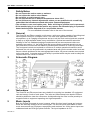
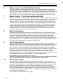
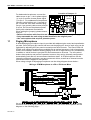
Z4II & Z8II Venue Mixer Installation & User Guide V9.0 Cloud Electronics Limited 140 Staniforth Road, Sheffield, S9 3HF England Tel + 44 (0) 114 244 7051 Fax + 44 (0) 114 242 5462 E-mail [email protected] Web site http://www.cloud.co.uk Z4II & Z8II: Installation and User Guide 1 Z8II & Z4II Venue Mixer Installation and operation manual Contents Section 22/10/04 V9 Page 1 Safety Notes...............................................................................3 2 General ......................................................................................3 3 Schematic Diagram ....................................................................3 4 Installation ..................................................................................3 5 Music inputs ...............................................................................3 6 Sensitivity & Gain Control...........................................................4 7 Music Control – Front Panel or Remote Plate ............................4 8 Music Equalisation .....................................................................4 9 Line 6 Input Priority ....................................................................4 10 Microphone inputs ......................................................................4 11 Paging Mic .................................................................................5 12 Microphone Gain Control ...........................................................6 13 Microphone Equalisation ............................................................6 14 High Pass Filter ..........................................................................6 15 Microphone Level Controls.........................................................6 16 Microphone priority.....................................................................7 17 Balanced Zone outputs ..............................................................7 18 Facility Input ...............................................................................7 19 Power Supply Capacity ..............................................................7 20 Microphone Priority over Facility Input ......................................8 21 Remote Music Mute – Fire Alarm Interface ................................8 22 Installing RSL-6 or RL-1 Remote Controls .................................8 23 Controlling the music functions using external DC control .........9 24 Plug-in Active Equalisation modules ........................................10 25 Active Modules – general specification ....................................10 25.1 AE-1 Aerobics Module..............................................................11 25.2 DM-1 Dual Microphone input module .......................................12 25.3 Wiring 2 or more DM-1’s in a daisy chain format......................13 Z4II & Z8II: Installation and User Guide 2 Contents (cont.) Section 22/10/04 V9 Page 25.4 LM-1 Mic/line plus remote control of music signals ................. 14 26 Solving problems ..................................................................... 15 26.1 Ground loops (aka Earth loops)............................................... 15 26.2 Connecting balanced signals to the unbalanced line inputs .... 15 27 EMC Considerations................................................................ 16 28 Technical Specifications .......................................................... 16 29 General specifications ............................................................. 16 Z4II & Z8II: Installation and User Guide 1 3 Safety Notes • Do not expose the unit to water or moisture. • Do not expose the unit to naked flames. • Do not block or restrict any air vent. • Do not operate the unit in ambient temperatures above 35oC. • Do not perform any internal adjustments unless you are qualified to do so and fully understand the hazards associated with mains operated equipment. • The unit has no user serviceable parts. Refer servicing to qualified service personnel. • If the moulded plug is cut off the lead for any reason, the discarded plug is a potential hazard and should be disposed of in a responsible manner. For more detailed information refer to the rear of the manual. 2 General The Cloud Z4 and Z8 are versatile, multi-source, multi-zone mixers capable of providing total sound system control for a complex venue. The units have applications where two microphones, up to 5 paging microphones and up to six line level music signals are required to feed up to eight separate areas in any combination. Optional accessories extend the flexibility of the unit: dedicated paging microphones with pre-announcement chime are available (see section 11), the music level and source can be controlled remotely on any zone and active modules can be added to provide special facilities on a zone by zone basis. The front panel controls are reduced to a minimum to reduce operational confusion and if preferred, the unit can be positioned in a protected area with just the remote music level and source controls positioned in the most appropriate location. All pre-set controls are mounted on the rear panel. A remote music mute facility is provided which may be used to satisfy the requirements of the Local Fire Officer. 3 Schematic Diagram 4 Installation The Cloud Z4 and Z8 venue mixers are suitable for mounting in a standard 19” equipment rack and occupy 3 units of rack space. The units are 160mm deep but a depth of 235mm should be allowed to clear the connectors. Avoid positioning the units in close proximity to magnetic fields or equipment operating at a high temperature. 5 Music Inputs Both the Z4 and Z8 operate in mono, however, all the line level music inputs are in stereo; these are internally mixed to form a mono signal. The six line inputs are suitable for most music sources such as CD players, tape players and receivers etc. All the stereo inputs are unbalanced and use RCA type phono sockets. The input impedance is 47kΩ. 22/10/04 V9 Z4II & Z8II: Installation and User Guide 4 6 Music Inputs - Sensitivity & Gain Control All six line inputs have a pre-set gain control on the rear panel, adjacent to the respective input sockets. The input sensitivity can be varied from –12dBu (195mV) to +8dBu (2.0V). The pre-set gain controls should be set so that all the input signals operate at the same level within the mixer so that the change in level when switching sources is minimal. The input gain controls can also be used to limit the amount of gain available from the user controls. 7 Music Control – Front Panel or Remote Plate The music source and music level control functions of a zone can be operated from the front panel or remotely via the optional RSL-6 remote source & level plate. When a remote control plate is connected to a zone, the rear panel mounted music control switch must be in the ‘Remote’ position. The RSL-6 can be positioned up to 100 metres from the mixer and two core cable with overall screen should be used. Self-adhesive labels are provided to identify the signal source on both the mixer front panel and the RSL-6. If it is preferred to provide remote control of the music level without remote source selection, the RL-1 remote level control can be wired to any zone using a two-wire connection (see section 21 for more installation details). The LM-1 active module also includes the remote music source and music level function (see section 24.4 for full details). 8 Music Equalisation Separate treble and bass controls are provided exclusively for the music signals on each zone. This arrangement allows the installer to optimise the response of the music signals on a zone by zone basis where different acoustic properties require optimal equalisation adjustment. The pre-set controls are located on the rear panel adjacent to the respective zone output connector. A flat response can be achieved by positioning the adjustment slot in the horizontal plane. The music treble control (HF) has a range of ±10dB at 10kHz and the music bass control operates with a range of ±10dB at 50Hz. 9 Line 6 input priority Both the Z4 and Z8 mixers have a facility to allow fully automatic priority to a JukeBox or Spot Announce Player. The Z4 mixer provides this facility on all four zones and the Z8 on all eight zones. Line 6 priority is activated by setting jumper J2 on the relevant zone board to the ‘ON’ position. When the priority is on, the mixer will operate normally until a signal is detected on line input 6, this causes the selected signal (usually background music) to mute, allowing the signal on line 6 to operate with priority. Once the signal on line 6 ceases, the selected music signal will smoothly restore to its former level. The time taken for this restoration can be 3, 6 or 12 seconds dependant on how internal jumper J3 has been set (for 12s restoration remove the jumper altogether). The factory default is 3s. When setting the jumper(s) please ensure that you: • Remove the mains cable from the rear of the product before removing the top panel. • Only reassemble the unit using screws identical to the original parts. 10 Microphone Inputs Two microphone inputs are provided and the microphone amplifier is an electronically balanced, transformerless design configured for optimum low noise performance. The input impedance is greater than 2kΩ and is suitable for microphones in the 200Ω to 600Ω range. Inputs are via gold plated female 3 pin XLR type connectors with latch and these are positioned on the rear panel. A facility to provide +15v phantom power is included and this can be activated by setting a jumper (adjacent to the Mic input connector on the mother board) to the ‘ON’ position. J1 applies to Mic 1, J2 applies to Mic 2 and the jumper J3 relates to the paging microphone input. The location of J1 is shown on the next page. 22/10/04 V9 Z4II & Z8II: Installation and User Guide 5 Location of Jumper J1 For balanced microphones, connect the MIC INPUT cable screen to pin 1, the in-phase signal VR3 VR2 SOCKET (+) to pin 2 and the reverse phase signal VR1 (-) to pin 3. For unbalanced microphones, HF LF SK1 GAIN "! connect a wire link from pin 1 (ground) to MICROPHONE PHANTOM pin 3 inside the XLR cable mounted plug; POWER #$$ use pin 1 as ground (cable screen) and pin % & %' ( & : 2 as hot. Do not use the phantom power (' 9 5 8 () 4 76 facility with unbalanced terminations. 3 ., /,+ When setting the jumper(s) please ensure * 01 2 that you: • Remove the mains cable from the rear of the product before removing the top panel. • Only reassemble the unit using screws identical to the original parts. • Use a microphone that requires phantom power. 11 Paging Microphone A dedicated paging microphone input is provided with adjacent gain control and equalisation pre-sets. Once the input gain control has been set the paging mic level of each zone can be optimised by adjusting the front panel mounted pre-set level controls. The Cloud CPM-4 & CPM-8 zone paging microphones are available as an optional accessory, both microphones feature zone selection switches allowing paging to all four or eight zones in any combination; in addition a ‘call all’ button is provided for announcements to all zones. The zone select buttons have push/on and push/off operation however, they can be internally configured to automatically reset after an announcement has been made. A CPM microphone can be internally configured to activate a pre-announcement chime, as well as an internal sounder so that the chime is audible to the operator. When using a single CPM paging microphone use the wiring diagram shown below: Wiring a CPM Microphone to a Z4 or Z8 Venue Mixer Up to 5 CPM paging microphones can be used with a Z4 or Z8 Venue Mixer, when wiring more than one CPM paging microphone either the Z4 or Z8 Venue Mixers please use the diagram on the following page: 22/10/04 V9 Z4II & Z8II: Installation and User Guide 6 Wiring Multiple CPM Paging Microphones to a Z4 or Z8 Venue Mixer In certain circumstances the Z4 and Z8 can power more than one CPM microphone, refer to section 19 for more details. The Z4 and Z8 mixers are compatible with general purpose paging microphones that are fitted with close-contact switches or open-collector switching devices. To open the paging microphone channel on any zone the relevant zone access switching terminal for that zone should be connected to 0V as shown in the diagram opposite. If all access terminations are permanently connected to 0V the paging microphone input will function as general purpose microphone input. 12 Microphone Gain Control PAGING MICROPHONE ZONE ACCESS SWITCHING 0V 8 7 6 5 4 3 2 1 +V Z8 Z7 Z6 Z5 Z4 Z3 Z2 Z1 Pre-set gain controls are provided adjacent to the respective XLR input connector. The gain can be adjusted from 10dB to 50dB and this wide range of gain allows direct connection of high output devices such as radio microphones without the need for additional attenuation. A high overload margin is maintained at all gain settings. LINK TO 0V TO OPEN RESPECTIVE ZONE 13 Microphone Equalisation Two-band equalisation is provided for both Mic 1 and Mic 2; the pre-set controls are positioned alongside the input connector and gain control on the rear panel. The characteristics of the equalisation is optimised for the tonal correction of speech signals and the treble control (HF) provides ±10dB at 5kHz with the bass control (LF) ±10dB at 100Hz. 14 High Pass Filter All three microphone channels feature high pass filters operating at 100Hz which provides effective attenuation of breath blasts and low frequency handling noises. The circuitry providing this feature is fixed and cannot be defeated. 15 Microphone Level Controls Separate front panel mounted controls for Mic 1 and Mic 2 level are provided for each zone. These controls provide the user with a convenient means to operate either microphone at a suitable level in any zone; rotating any mic level control to the fully anti-clockwise position effectively turns the microphone off. The microphone signals are routed directly to the main output stage of the respective zone and mic signals are totally unaffected by the operation of the music controls. The Mic 1 & Mic 2 gain controls on the rear panel should be set at a level where it is not possible to have excessive gain even when the front panel level controls are fully clockwise. For the benefit of the operator, self adhesive labels are provided to identify the microphone channels and these can be fixed on the mixer front panel in the space provided to the left of the level controls. 22/10/04 V9 Z4II & Z8II: Installation and User Guide 16 7 Microphone Priority Fully automatic, voice operated priority is provided. When any microphone is used, the music signals will attenuate by approximately 30dB; after the announcement, the music signals will restore smoothly to their former level. Priority over Mic 1 & Mic 2 is provided for the paging mic only; when a paging announcement is made, this has full priority over any signal present on both the Mic 1 and Mic 2 channels. In certain circumstances, the priority functions may be undesirable; the Mic 1 & Mic 2 priority over music can be disabled by configuring J6 to the ‘OFF’ position on the respective zone board. When more than one paging mic is used, the use of any paging mic will inhibit the operation of all other paging mics, and the paging microphone ‘busy’ LED will illuminate. The paging mic priority can be triggered by voice detection or by the grounding of the access contact; the jumper J5 can be set to ‘VOX’ for voice triggering (default) or set to ‘SW’ for access contact triggering. A separate jumper (J5) is located on each zone board 17 Balanced Zone Outputs Each zone has a balanced output, using a 3 pole ‘Phoenix’ type connector that can operate into loads as low as 600Ω. The nominal output level is 0dBu (775mV) but the mixer can operate with a wide range of signals up to a maximum output level of +20dBu (7.75V). For balanced interconnections, 2-core screened cable should be used. Connect the screen to pin 1, the reverse phase signal (normally blue or black) to pin 2 and the in-phase signal (normally red) to pin 3. If you wish to connect any zone output to an unbalanced input, connect the cable screen to pin 1 with the hot connection (inner core) to pin 3 and make no connection to pin 2. 18 Facility Input - + B ALA NC ED INP U T B AL ANC ED IN PU T N O IS E R EM O TE Each zone is fitted with a facility input; this 9 pin GATE LE VEL sub D connector provides direct access to the NC GA TE R EM O TE S OU R C E respective zone and is primarily used to connect one LOG IC 0V 5 4 3 2 1 of the dedicated active modules, AE-1, DM-1 or 9 8 7 6 LM-1. The active modules extend the facilities of the FAC ILITY N O IS Y 0V mixer on a zone by zone basis by providing remotely C ONN E CTO R V CA located zone access and control, for example, the C ONTR O NTR OL OL C -15V V OLTA G E +15V AE-1 module can be used to provide a direct input into a particular zone specifically for aerobic 0V purposes (see section 24.1). The DM-1 module is fitted with two balanced microphone inputs; the module can be used in multiples (see section 24.3) and the LM-1 module provides one balanced microphone input, a line level music input and remote control of the mixer’s music source and level (see section 24.4). The facility input can also be used as a direct input to the respective zone via a line level balanced input. Important note: Refer to Section 19 before installing any active module 19 Power Supply Capacity The power supplies of the Z4II and Z8II venue mixers have an external load capacity of 120mA for the Z4II and 190mA for the Z8II. Care should be taken when wiring or connecting modules and external devices to the Z4II and Z8II mixers since exceeding the external load capacity risks temporary power supply failure. The table below lists the current consumption of each compatible Z4II and Z8II module and external device. External Active Device / Internal Module CPM 4 & 8 AE-1 DM-1 LM-1 Bose EQ: M8, M32, MA12, 402, 502A, 802, MB4, MB24, 502B, 502BEX Bose EQ: LT3302, LT4402, LT9402, LT9702 Bose EQ: M16 22/10/04 V9 Current Consumption 40mA 9mA 18mA 12mA 12mA 17mA 24mA Z4II & Z8II: Installation and User Guide 8 If the mixer has a CPM paging microphone installed, you have the option to power the microphone with the ‘CPM-PSU’ external power supply. This will reduce the load on the system by 40mA. If a power supply failure occurs switch off the mixer and disconnect the remote modules, the mixer should be left off for approximately 30 seconds to allow it to reset. Check the wiring and total current consumption of the external active devices before reconnecting the power and if the problem persists contact our technical department. 20 Microphone Priority over Facility Input Every vertically oriented zone board has a jumper marked J4 - this jumper sets the microphone over facility signal priority. In the OFF position (default) all microphones will not override the signals of the facility input (i.e. AE-1, DM-1 or LM-1). In the ON position, MIC 1, MIC 2 and the paging mic have a 30dB priority over the facility input. When setting the jumper(s) please ensure that you: • Remove the mains cable from the rear of the product before removing the top panel. • Only reassemble the unit using screws identical to the original parts. 21 Remote Music Mute – Fire Alarm Interface In certain circumstances, there may be a requirement to mute the music signals via a fire alarm control panel in an alarm condition. The Cloud Venue Mixer provides a facility to mute the music signals by connecting the two pole music mute connector to a pair of relay contacts that are controlled by the fire alarm control panel. The jumper J4 on the mother board (adjacent to the power transformer) selects N/O (normally open – default) or N/C (normally closed) contact arrangements. The two-wire connection should not be connected to any other circuit or voltage. In most instances, the fire alarm company will provide the relay. All the microphone facilities operate normally when the music mute is operating. 22 Installing RSL-6 or RL-1 Remote controls The remote control plates, RSL-6 and RL-1 are compatible with UK domestic electrical accessories and can be mounted onto a standard British flush or surface mounted 25mm deep back box. Two-core cable with overall screen should be used to connect the remote controls to the Cloud Mixer; because REMOTE CONTROL OF MUSIC SOURCE AND LEVEL both functions are voltage controlled, MIXER a cable length of up to 100 metres can RSL-6 3 POLE CONNECTOR be used. When using the RSL-6 remote control plate, the ‘music 1 2 3 1 2 3 MUSIC CONTROL control’ switch (on the mixer rear REMOTE (IN) panel) should be in the ‘remote’ position. If you propose to use the RL1 remote level control on any zone, MUSIC CONTROL SWITCH SHOULD STANDARD WIRING CONVENTION BE SET TO THE 'REMOTE' POSITION USE TWO CORE SCREENED CABLE set the ‘music control’ switch to the ‘remote’ position and the PCB mounted jumper J1 on the respective REMOTE CONTROL OF MUSIC LEVEL (WITH FRONT PANEL SOURCE SELECTION) zone board to the ‘FR’ position to MIXER RL-1 3 POLE MUSIC CONTROL allow front panel control of the music CONNECTOR REMOTE (IN) source. 1 2 3 1 When setting the jumper(s) please ensure that you: • Remove the mains cable from the rear of the product before removing the top panel. • Only reassemble the unit using screws identical to the original parts. 22/10/04 V9 2 FOR APPLICATIONS THAT REQUIRE REMOTE CONTROL OF THE MUSIC LEVEL WITH FRONT PANEL SOURCE SELECTION 3 MUSIC CONTROL SWITCH SHOULD BE SET IN THE 'REMOTE' POSITION SOURCE SELECT J1 FR SW PCB JUMPER J1 SHOULD BE SET TO THE 'FR' POSITION ATTENTION! REMOVE POWER CABLE BEFORE MAKING ANY INTERNAL ADJUSTMENTS Z4II & Z8II: Installation and User Guide 23 9 Controlling the music functions using external DC control The Cloud Z4 and Z8 can be used as part of an automated sound system by controlling the music level and music source by an external 0-10V DC voltage. The 3-pole connector normally used to terminate the RSL-6 control plate can be used to feed two separate control voltages into the mixer on a zone by zone basis. Pin 1 is a ground (0V) termination common to both control voltages; this should be connected to the technical ground (0V) of the voltage source, Pin 2 is the control voltage input for the music level and pin 3 is used to control the music source selection. Control of music level A maximum gain reduction of 60dB can be achieved with a control voltage of +10V; the rate of attenuation is approximately 165mV per dB. A control voltage of zero realises unity gain (full volume), however, with no external connection to pin 2, an internal 4k7 resistor connected to +15V will ‘pull up’ the control voltage to provide maximum attenuation. The output impedance of the control voltage source should be low enough to overcome the influence of this resistor. Music source selection Here are the details of the music source select control voltages (pin 3) required to switch the six line input signals: Off >+9.0V Line 1 +7.5V Line 2 +6.0V Line 3 +4.5V Line 4 +3.0V Line 5 +1.5V Line 6 0V With no external connection to pin 3, an internal 15k resistor connected to +15V will ‘pull up’ the source select control voltage and the ‘off’ position will be selected. The output impedance of the control voltage source should be low enough to overcome the influence of this resistor. If you would like to fix the music signal to a particular line input, wire a fixed resistor from the table below between pins 1 & 3 on the remote control connector: Line 1 Line 2 Line 3 Line 4 Line 5 Line 6 16k 11k 6k8 3k9 1k8 shorting link If the control voltage source is not isolated from the power earth, there is a small risk of creating a ‘ground loop’ by linking the mixer technical ground (0V) to the ground (0V) of the equipment providing the control voltages. To minimise this risk of a ground loop occurring, we suggest that all pieces of equipment be positioned in close proximity and supplied from the same power outlet. 22/10/04 V9 Z4II & Z8II: Installation and User Guide 10 24 Plug-in Active Equalisation modules. Each zone board has the facility to connect a plug-in equalisation module. When fitting a module to one of the zone boards, proceed as follows: • Disconnect the power connector from the mixer. • Remove the top panel. • Locate the zone board for the zone to which the EQ card is to be fitted. The zone boards run vertically up the inside of the unit. • Locate CON 2, the EQ card connector on the zone board. Fit the EQ module to the connector. The EQ card should be perpendicular to the zone board. • Apply moderate pressure to the EQ module, towards the zone board, until it locates with a click. • Replace the top panel Zone board fitted with EQ Module Important note: Refer to Section 19 before installing an Active Equalisation Module EQ Modules currently available are: Bose® M8, M32, MA12, 402, 502A, 802, MB4, MB24, 502B, 502BEX, LT3302, LT4402, LT9402, LT9702, M16. 25 Active Modules – general specification. The Cloud AE-1, DM-1 & LM-1 are the same physical size as a double UK electrical socket (13A type) and can be mounted in the recessed back box provided or be surfaced mounted in a standard 35mm deep housing. The modules should be connected to the facility input of the host mixer using a single multi-core screened cable. The module terminations are conventional screw terminals and the facility input on the host mixer is a 9-pin sub-D type connector. A suitable 9 pin sub-D connector is provided. GREAT CARE MUST BE TAKEN WHEN TERMINATING THE MODULES; POWER IS DERIVED FROM THE HOST MIXER AND CERTAIN WIRING ERRORS CAN CAUSE POWER SUPPLY PROBLEMS RESULTING IN TEMPORARY FAILURE OF THE MIXER; ALWAYS CHECK YOUR WIRING BEFORE TESTING THE SYSTEM. Please refer to section 18 for further details of the facility input connector. 22/10/04 V9 Z4II & Z8II: Installation and User Guide 25.1 11 AE-1 Aerobics Module The Cloud AE-1 is a remotely located active module with facilities for a line level music input and an unbalanced microphone input. The AE-1 is compatible with the Cloud Z4, Z8 and the MPA-626 and can be used for any application where the facilities provided match the system requirements; the prime application being the fitness suite where the aerobic instructor is required to connect their music source and radio microphone directly into the house system. Use 8 core screened cable to link the AE-1 to the facility input. Important note: Refer to Section 19 before installing an AE-1 AE-1 CONNECTION TABLE CONNECTOR 9 PIN SUB D AE-1 Terminals 22/10/04 V9 1 N/C 2 N/C 3 8 4 7 PIN NUMBER 5 6 7 2 5 4 8 6 9 1 SHELL 3 Z4II & Z8II: Installation and User Guide 12 25.2 DM-1 Dual Microphone Input Module The Cloud DM-1 is a remotely located active module with two balanced microphone inputs via 3 pin female XLR connectors. Each input has a level control and overall equalisation is provided by tamperproof treble and bass controls. A ‘music ducking’ switch provides priority over the main system music if required. Modules can be linked when wired in a ‘daisy chain’ format (see section 24.3). Use 8 core screened cable to link the DM-1 to the facility input and 6 core screened cable when wiring more modules in the ‘daisy chain’ format. Important note: Refer to Section 19 before installing a DM-1 DM-1 CONNECTION TABLE CONNECTOR 9 PIN SUB D DM-1 Terminals 22/10/04 V9 1 N/C 2 N/C 3 5 4 6 PIN NUMBER 5 6 7 2 7 8 8 4 9 1 SHELL 3 Z4II & Z8II: Installation and User Guide 25.3 22/10/04 V9 Wiring 2 or more DM-1’s in a daisy chain format. 13 Z4II & Z8II: Installation and User Guide 14 25.4 LM-1 Mic/line plus remote control of music signals. The Cloud LM-1 is a remotely located active module with a balanced microphone input, a line level music input and music source select & level controls (rather like a built in RSL-6). A microphone priority switch provides the option to reduce the level of the music signal when the mic is used. Use 9 core screened cable to wire the LM-1 to a facility input on any zone of the Z4 or Z8. When an LM-1 is connected to a zone please ensure that the music control switch is set to the ‘remote’ position. (Jumper ‘J1’ must be in the factory default ‘SW’ position). Important note: Refer to Section 19 before installing an LM-1 LM-1 CONNECTION TABLE CONNECTOR 9 PIN SUB D LM-1 Terminals 22/10/04 V9 1 1 2 2 3 7 4 6 PIN NUMBER 5 6 7 4 9 10 8 8 9 5 SHELL 3 Z4II & Z8II: Installation and User Guide 26 Solving problems 26.1 Ground loops (aka Earth loops) 15 Despite your best efforts, if the completed sound system ‘hums’ you probably have a ‘ground loop’; the offending signal source can be found by setting the volume control to minimum then disconnecting the input leads (both left & right channels) on each line input until the ‘hum’ disappears. This problem is often caused by terminating a screened input cable into a signal source positioned a significant distance from the mixer. A good way of avoiding this potential problem is to use signal sources (CD players and the like) that are double insulated with no connection to the mains supply earth. If a signal feed were derived from a second mixer (a club or microphone mixer for example) it would be perfectly normal to expect this to be earthed; we suggest that a transformer be used to isolate the signal and prevent a noisy loop (see section 25.2). 26.2 Connecting balanced signals to the unbalanced line inputs. We recommend the use of a transformer to convert a balanced signal to an unbalanced signal suitable for direct connection to the mixer line inputs. The transformer should be mounted close to the Zone Mixer and the unbalanced output lead should be kept as short as possible. Where both the source unit and destination mixer are earthed, it is important to isolate the primary and secondary windings to avoid a potential ground loop; if there is any doubt about this, we suggest that the balanced cable screen is not connected at the transformer end. Suitable transformers for this application are the RS Components 210-6447 (primary & secondary series connected) and we recommend the fitting of the screening can (part number 210-6469); Canford Audio supply a similar transformer OEP Z1604 but we suggest that these should be fitted in a screened housing. All transformers should be wired to give a ratio of 1:1. 22/10/04 V9 Z4II & Z8II: Installation and User Guide 16 27 EMC Considerations The Cloud Z4 & Z8 fully conform to the relevant electromagnetic compatibility (EMC) standards and are technically well behaved; you should experience no operational problems and under normal circumstances, no special precautions need to be taken. If the unit is to be used within close proximity to potential sources of HF disturbance such as high power communications transmitters, radar stations and the like, the performance of the mixer may be reduced; we suggest that the microphone cable screen be connected to the shell of the XLR type connector and the line input leads are kept as short as possible. 28 Technical Specifications Line inputs 20Hz-20kHz ±0.5dB <0.05% 20Hz -20kHz 195mV (-12dBu) to 2.0V (+8dBu) 20dB range 47kΩ >20dB -90dB A weighted (0dB gain) HF: ±10dB/10kHz LF: ±10dB/50Hz Frequency Response Distortion Sensitivity Input Gain Control Input Impedance Headroom Noise Equalisation Microphone Inputs 100Hz / -3dB(filter) 20kHz ±0.5dB <0.05% 20Hz-20kHz 10dB-50dB >2kΩ (balanced) +15V (PCB jumper for on/off) >20dB -120dB EIN 22Hz-22kHz (150Ω) HF: ±10dB/5kHz LF: ±10dB/100Hz Frequency Response Distortion Gain Range Input Impedance Phantom power Headroom Noise Equalisation Facility Input Input Impedance Sensitivity Noise Gate 10kΩ (balanced) pin 3(+) pin 4(-) 0dBu – 775mV Ground pin 5 to open Outputs Balanced Zone Outputs Minimum load impedance Maximum output level 29 General Specifications Power input Fuse rating Fuse type Dimensions Weight 22/10/04 V9 775mV (0dBu) 3 pin ‘Phoenix’ type connector 600 ohms +20dBu (7.75V) 230V ±10% 115V ±10% AC 40-60Hz Z8: 230V – T125mA H 115V – T250mA H Z4: 230V – T100mA H 115V – T200mA H 20mm x 5mm 250V 482.60mm x 132.50mm(3U) x 160.00mm deep (+ connectors) Z4 3.83 kg net Z8 4.40 kg net Z4II & Z8II: Installation and User Guide 17 This product conforms to the following European EMC Standards: BS EN 55103-1:1997 BS EN 55103-2:1997 This product has been tested for use in commercial and light industrial environments. If the equipment is used in controlled EMC environments, the urban outdoors, heavy industrial environments or close to railways, transmitters, overhead power lines etc. the performance of the unit may be degraded. The product conforms to the following European electrical safety standard. BS EN 60065:1998 Safety Considerations and Information The unit must be earthed. Ensure that the mains power supply provides an effective earth connection using a three-wire termination. When the mains switch is in the off ‘O’ position the live and neutral conductors of the mains transformer are disconnected. CAUTION – Installation Do not expose the unit to water or moisture Do not expose the unit to naked flames. Do not block or restrict any air vent Do not operate the unit in ambient temperatures above 35oC CAUTION – Hazardous Live Do not touch any part or terminal carrying the hazardous live symbol ( ) while power is supplied to the unit. Terminals to which the hazardous live symbol refers require installation by a qualified person. CAUTION - Mains Fuse Replace the mains fuse only with the same type and rating as marked on the rear panel. The fuse body size is 20mm x 5mm. CAUTION – Servicing The unit contains no user serviceable parts. Refer servicing to qualified service personnel. Do not perform servicing unless you are qualified to do so. Disconnect the power cable from the unit before removing the top panel and do not make any internal adjustments with the unit switched on. Only reassemble the unit using bolts/screws identical to the original parts Bose is a registered trademark of The Bose Corporation In the interest of continuing improvements Cloud Electronics Limited reserves the right to alter specifications without prior notice. Cloud Electronics Limited 140 Staniforth Road Sheffield S9 3HF England Telephone +44 (0) 114 244 7051 Fax +44 (0) 114 242 5462 E-mail: [email protected] 22/10/04 V9