1
NETWORK CAMERA
Operation Guide
Before using the product, be sure to read the Start Guide and this Operation Guide.
Introduction
Thank you for purchasing Canon Network Camera VB-C60/VB-C60B (hereafter referred to as
VB-C60).
The only difference between VB-C60 and VB-C60B is the body color.
This Operation Guide describes how to set up and use VB-C60. Read this guide carefully before
using VB-C60 to ensure that you make the best possible use of this product. Also, be sure to read
the ReadMe file on the Setup CD-ROM.
For the latest information, please refer to the Canon Web site.
Exclusion of Liability
If the Product is connected to a recording device, Canon Inc. shall not be responsible for
any financial losses that may be incurred as a result of the loss of recorded information or
images, regardless of the internal or external cause of the loss.
Copyright
Videos, images or sounds recorded with your VB-C60 may not be utilized or published, without
consent of copyright holders, if any, except in such a way as permitted for personal use under the
relevant copyright law.
Notes
1. All rights reserved.
2. The contents of this guide are subject to change without any notice.
3. Every effort has been made to ensure that this guide is flawless. However, if you find any
errors, please contact us.
4. Notwithstanding the above, Canon shall not be responsible for any effects resulting from the
use of this guide.
Notes on privacy and publicity rights regarding the utilization of video/audio
When using VB-C60 (for video or audio recording), it is the responsibility of the users to
take all care to protect privacy and avoid any violation of publicity rights. Canon shall have
no liability whatsoever in this regard.
<Reference>
●Please be sure to gain approval of the building management office before installing a
camera, if copyrighted architectural structures or copyrighted premises are got into the
frame.
Legal Notice
In some countries or regions, monitoring via a camera is banned by the law or regulation,
and the law or regulation depends on the country or region.
Before using VB-C60, confirm the law or regulation of the country or region where the
camera is used.
ii
Introduction
Trademark Notice
● Canon and the Canon logo are registered trademarks of Canon Inc.
● Microsoft Windows and Microsoft Internet Explorer are trademarks or registered trademarks of
Microsoft Corporation in the United States and other countries.
● Windows is legally recognized as the Microsoft Windows Operating System.
● Other brands or product names in this guide are trademarks or registered trademarks of their
respective companies.
WARNING : To reduce the risk of electric shock, do not expose this appliance to rain or
moisture.
Use of Bundled Software “VK-Lite” (Disclaimer)
Malfunction, failure of VK-Lite or other factors may cause problems, such as recording
failure, recorded data corruption or loss. Canon shall have no liability whatsoever for any
loss or damages incurred by the user as a result of such problems.
iii
Introduction
MPEG-4
NOTICE ABOUT THE MPEG-4 VISUAL STANDARD: THIS PRODUCT IS LICENSED
UNDER THE MPEG-4 VISUAL PATENT PORTFOLIO LICENSE FOR THE PERSONAL
AND NON-COMMERCIAL USE OF A CONSUMER TO (i) ENCODING VIDEO IN
COMPLIANCE WITH THE MPEG-4 VISUAL STANDARD (“MPEG-4 VIDEO”) AND/OR
(ii) DECODING MPEG-4 VIDEO THAT WAS ENCODED BY A CONSUMER ENGAGED
IN A PERSONAL AND NON-COMMERCIAL ACTIVITY. NO LICENSE IS GRANTED OR
SHALL BE IMPLIED FOR ANY OTHER USE. ADDITIONAL INFORMATION INCLUDING
THAT RELATING TO PROMOTIONAL, INTERNAL AND COMMERCIAL USES AND
ADDITIONAL LICENSING MAY BE OBTAINED FROM MPEG LA, LLC. SEE HTTP://
WWW.MPEGLA.COM.
“This product is licensed under AT&T patents for the MPEG-4 standard and may be used
for encoding MPEG-4 compliant video and/or decoding MPEG-4 compliant video that was
encoded only (1) for a personal and non-commercial purpose or (2) by a video provider
licensed under the AT&T patents to provide MPEG-4 compliant video. No license is granted
or implied for any other use for MPEG-4 standard.”
Third Party’s Software
The product (network camera and bundled VK-Lite viewer) contains third party’s software
modules. For detail information, please refer to ReadMe-E.txt on the supplied CD-ROM.
Each module’s license conditions are also available in the License folder on the same
CD-ROM.
Software under GPL and LGPL
If you would like to obtain the source code under GPL/LGPL, please contact the dealer,
where you purchased the product, or a sales agent.
iv
Contents
Introduction ...................................................................................................... ii
Contents ........................................................................................................... v
How to Read the Guides .............................................................................. viii
User’s Manual ........................................................................................................... viii
Icons using in this Guide ............................................................................................. ix
Camera’s Top Page .......................................................................................... x
Access Camera’s Top Page ......................................................................................... x
Access the Setting Menu ............................................................................................ xi
Access the Sample Pages .......................................................................................... xi
Access the VB-C60 Viewer ........................................................................................ xii
User Authentication for Accessing the Setting Menu or Admin Viewer ..................... xiii
Chapter 1 Detailed Settings
Setting Menu ................................................................................................. 1-2
Access the Setting Menu ............................................................................. 1-4
Setting Menu ............................................................................................................ 1-4
Common Items ......................................................................................................... 1-5
Set Administrator Password, LAN, IPv6 and DNS (Network) .................... 1-7
Set the Date and Time (Date and Time) ..................................................... 1-11
Set the Camera Control and External Device Names (Camera) ............. 1-13
Set the Image Size, Quality and Frame Rate (Image) .............................. 1-19
Set HTTP Upload, FTP Upload and E-mail Notification (Upload) ........... 1-21
Set Up the Image, Audio and HTTP Servers (Server) .............................. 1-26
Set Image Buffering, Motion Detection, Audio Playback,
Interval Timer (Event) ................................................................................. 1-29
Set User Access Privileges (Access Control) .......................................... 1-35
Set IPsec (IPsec) ......................................................................................... 1-39
Setting Items That Require a Reboot (Reboot) ........................................ 1-42
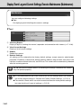
Display Event Log and Current Settings,
Execute Maintenance (Maintenance) ........................................................ 1-44
Chapter 2 VBAdminTools
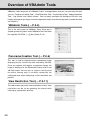
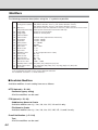
Overview of VBAdmin Tools ......................................................................... 2-2
VBAdmin Tools .........................................................................................................
Panorama Creation Tool ..........................................................................................
View Restriction Tool ................................................................................................
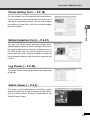
Preset Setting Tool ...................................................................................................
Motion Detection Tool ..............................................................................................
Log Viewer ...............................................................................................................
Admin Viewer ...........................................................................................................
2-2
2-2
2-2
2-3
2-3
2-3
2-3
v
Contents
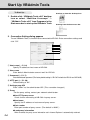
Start Up VBAdmin Tools ............................................................................... 2-4
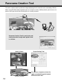
Panorama Creation Tool ............................................................................... 2-6
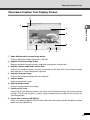
Panorama Creation Tool Display Screen ................................................................. 2-7
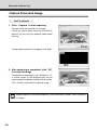
Capture Panorama Image ........................................................................................ 2-8
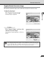
Register/Delete Panorama Image ............................................................................ 2-9
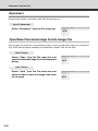
Reconnect .............................................................................................................. 2-10
Open/Save Panorama Image from/to Image File .................................................. 2-10
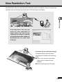
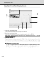
View Restriction Tool .................................................................................. 2-11
View Restriction Tool Display Screen .................................................................... 2-12
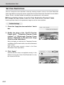
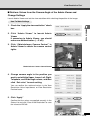
Set View Restrictions ............................................................................................. 2-14
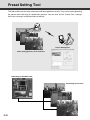
Preset Setting Tool ...................................................................................... 2-18
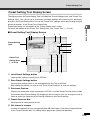
Preset Setting Tool Display Screen ........................................................................ 2-19
Set Presets ............................................................................................................ 2-21
Preset Tour ............................................................................................................. 2-24
Motion Detection Setting Tool ................................................................... 2-27
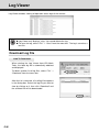
Log Viewer ................................................................................................... 2-36
Download Log File ................................................................................................. 2-36
View Logs .............................................................................................................. 2-37
Chapter 3 VB-C60 Viewer
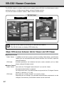
VB-C60 Viewer Overview .............................................................................. 3-2
Major Differences between Admin Viewer and VB Viewer ....................................... 3-2
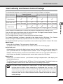
User Authority and Camera Control Privilege .......................................................... 3-3
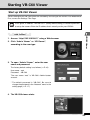
Starting VB-C60 Viewer ................................................................................ 3-5
Start up VB-C60 Viewer ........................................................................................... 3-5
Close VB-C60 Viewer .............................................................................................. 3-6
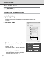
Connect from the VBAdmin Tools ............................................................................ 3-6
How to Operate the VB-C60 Viewer ............................................................. 3-8
“Admin Viewer” Display Screen ............................................................................... 3-8
“VB Viewer” Display Screen ................................................................................... 3-10
Obtain the Camera Control ..................................................................................... 3-11
Control the Camera ................................................................................................ 3-12
Configure Image and Audio Settings ..................................................................... 3-17
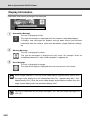
Display Information ................................................................................................ 3-20
Operating and Setting as Administrator ................................................... 3-21
vi
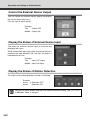
Open the Control for Admin Panel .........................................................................
Control the External Device Output .......................................................................
Display the Status of External Device Input ...........................................................
Display the Status of Motion Detection ..................................................................
Control and Set the Camera ..................................................................................
Set the Focus .........................................................................................................
Set the Exposure ...................................................................................................
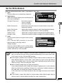
Set the White Balance ...........................................................................................
3-21
3-22
3-22
3-22
3-23
3-24
3-25
3-27
Contents
Set the Smart Shade Control ................................................................................. 3-28
Set the Night Mode ................................................................................................ 3-28
Chapter 4 Creating Web Pages for Video Distribution
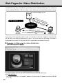
Web Pages for Video Distribution ............................................................... 4-2
View Sample Pages ...................................................................................... 4-4
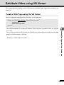
Distribute Video using VB Viewer ................................................................ 4-5
Create a Web Page using the VB Viewer ................................................................
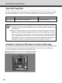
Save Web Page Data ..............................................................................................
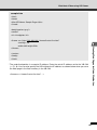
Example of Using the VB Viewer to Create a Web Page ........................................
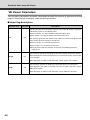
VB Viewer Parameters .............................................................................................
4-5
4-6
4-6
4-8
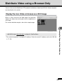
Distribute Video using a Browser Only ....................................................... 4-9
Display the Live Video at Access as a Still Image ................................................... 4-9
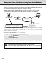
Example of Video Distribution using One Global Address ..................... 4-10
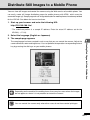
Distribute Still Images to a Mobile Phone ................................................ 4-11
Overwrite Sample Pages ....................................................................................... 4-12
Chapter 5 Appendix
Modifiers .................................................................................................................. 5-2
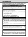
Troubleshooting ............................................................................................ 5-4
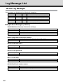
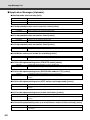
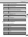
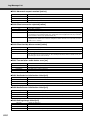
Log Message List .......................................................................................... 5-6
VB-C60 Log Messages ............................................................................................ 5-6
VB-C60 Viewer Message List ..................................................................... 5-12
Messages displayed in the Information Field ......................................................... 5-12
Restore the Factory Default Settings ........................................................ 5-14
Restore the Factory Default Settings from the Maintenance Menu Using a
Web Browser ....................................................................................................... 5-14
Initialize the Camera using the Reset Switch ......................................................... 5-15
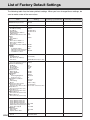
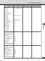
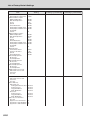
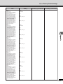
List of Factory Default Settings ................................................................. 5-16
Index ............................................................................................................ 5-20
vii
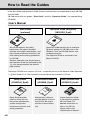
How to Read the Guides
In the Start Guide and Operation Guide, the text and illustrations are applicable for both VB-C60
and VB-C60B.
VB-C60 comes with two guides; “Start Guide” and this “Operation Guide” (on supplied Setup
CD-ROM).
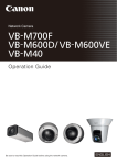
User’s Manual
Start Guide
(enclosed)
Operation Guide (this guide)
(VBC60OG_E.pdf)
Start Guide explains the safety
precautions, the types of bundled
software, the system requirements, and
the software installation instruction, the
initial setting and mounting procedures
for VB-C60.
Sections where the user should refer to
the Operation Guide are indicated by the
d icon accompanied by the relevant
page number.
Operation Guide explains how to configure
the basic settings for VB-C60, how to use
VBAdmin Tools and VB-C60 Viewer, and
troubleshooting tips.
The Operation Guide is contained in the
Setup CD-ROM.
The Setup CD-ROM also contains “VK-Lite”, a simplified version of the Network Video Recorder
(→dStart Guide P.1-6). The instruction manuals below are provided for VK-Lite.
viii
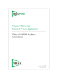
Setup Guide
Administrator’s Manual
Viewer Operation Guide
(VK20SUG_E.pdf)
(VK20AM_E.pdf)
(VK20VOG_E.pdf)
Setup Guide provides
notes for using VK-Lite,
the system requirements,
system configuration,
installation instruction and
setup procedures.
Administrator’s Manual
provides details of how to
use VK-Lite. Be sure to
read this manual before
use.
Viewer Operation Guide
is the operation guide for
VK-Lite Viewer. For
detailed information on
how to use VK-Lite
Viewer, refer to the
“Administrator’s Manual”.
How to Read the Guides
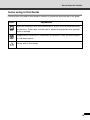
Icons using in this Guide
Following icons are used to draw reader’s attention to particularly important text in this guide.
Icon
Note
Tip
d
Explanation
Important information that must be observed or actions that are prohibited during
an operation. These notes must be read to prevent the equipment from possible
faults or damage.
Supplementary information or a reference to the operation. Users are recommended
to read these memos.
Please refer to Start Guide.
ix
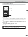
Camera’s Top Page
This section explains the VB-C60’s top page including the setting menus and how to access the
VB-C60 viewer.
First, you need to access the camera’s top page using a Web browser.
From the page, you can open the VB-C60 viewer for displaying video or the setting page for
detailed settings of the camera.
When you access VB-C60 for the first time, please refer to the Start Guide comes with
VB-C60.
Note
In this guide, the IP address “192.168.100.1” (factory default setting) is used to explain
how to operate the camera. In actual operation, use the IP address that you set in
your VB-C60.
Access Camera’s Top Page
1. Access http://192.168.100.1/ in the Web browser
2. The camera’s top page appears
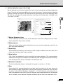
The overview of each link is as follows.
1
1 Language button
Click this button to change the language
to be displayed.
2
3
2 Link to Setting Page (Setting Menu)
Click this link to display the setting menus.
4
3 Link to Sample Pages
Click this link for sample images.
4 Link to VB-C60 viewer
Click to start the VB-C60 viewer that
displays video from VB-C60 in the Web
browser.
The VB-C60 viewer includes two viewers:
“Admin Viewer” and “VB Viewer”
(➞ P.3-2).
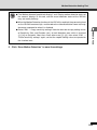
● Explanation of each link
Admin Viewer
Click to start Admin Viewer.
VB Viewer
Click to start VB Viewer.
x
Camera’s Top Page
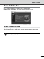
Access the Setting Menu
Click 2 Setting Page to move to the setting page for detailed settings.
For details on the Settings Menu, see Chapter 1 “Detailed Settings”(➞ P.1-2).
Access the Sample Pages
Click 3 Sample Page to access the sample pages.
You can view three types of sample pages: still image, video, and image for mobile phone.
Tip
For detailes on how to utilize the sample pages, see Chapter 4 “Creating Web Pages
for Video Distribution”(➞ P.4-2).
xi
Camera’s Top Page
Access the VB-C60 Viewer
Click the “Admin Viewer” or “VB Viewer” link under 4 “VB-C60 Viewer” to access the VB-C60
viewer.
Admin Viewer
VB Viewer
xii
Camera’s Top Page
User Authentication for Accessing the Setting Menu or Admin Viewer
User authentication is required to access the “Setting
Menu” or “Admin Viewer”.
The factory default setting is as follows.
User name : root
Password : VB-C60
The user name “root” is the Administrator account of
VB-C60.
from Setting Page
from Admin Viewer
Note
● When Administrators and Authorized users use the VB-C60 viewer on the same PC,
it is strongly recommended not to check the “Remember my password” checkbox.
● Be sure to enter the correct user name and password. If entering a wrong one, try
again with the correct name and password.
● Be sure to change the Administrator password for system security. Do not forget
the new password.
● If you forgot the Administrator password, press the camera’s reset switch to restore
the factory default setting (➞ P.5-15). However, note that all settings are restored
to the factory default settings.
● If you need to delete sample pages (➞ P.4-4) for security reasons, be sure to
access the following path using FTP and copy the files to PC or other devices for
backup, before deleting.
Path to the Japanese version sample: /mnt_flash/www/html/sample/
Path to the English version sample: /mnt_flash/www/html/sample/
To restore deleted sample pages, you need to write back the copied files to the
above path. So, be sure to back up the files before deleting sample pages.
Tip
For more information on VB-C60 viewer and the user type, see Chapter 3 “VB-C60
Viewer” (➞ P.3-2).
xiii
Chapter
Detailed Settings
This chapter describes the detailed settings for VB-C60
such as network connection, camera control, date, time and
access control.
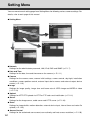
Setting Menu
You can move to each setting page from Setting Menu for following various camera settings. For
details, refer to each page of this manual.
● Setting Menu
● Network
Settings for the administrator password, LAN, IPv6, DNS and SNMP (➞ P.1-7)
● Date and Time
Settings for the date, time and time zone on the camera (➞ P.1-11)
● Camera
Settings for the camera name, camera initial settings, camera control, day/night, installation
conditions, camera position control, external input device names and external output device
names (➞ P.1-13)
● Image
Settings for image quality, image size and frame rate of JPEG image and MPEG-4 video
(➞ P.1-19)
● Upload
Settings for HTTP/FTP upload via HTTP or FTP and e-mail notification (➞ P.1-21)
● Server
Settings for the image server, audio server and HTTP server (➞ P.1-26)
● Event
Settings for image buffer, motion detection, external device input, interval timer and voice file
upload (➞ P.1-29)
● Access Control
Settings for the authorized user account, user authority and host access restriction (➞ P.1-35)
1-2
Setting Menu
● IPsec
Settings for IPsec (➞ P.1-39)
● Reboot Item
Settings for items that require a reboot after the setting (➞ P.1-42)
Detailed Settings
● Maintenance
Viewing of the event log and current settings, rebooting the camera, and restoring the factory
default settings (➞ P.1-44)
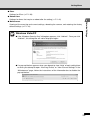
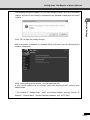
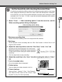
Windows Vista/XP
Note
● If the “Windows Security Alert” dialog box appears, click “Unblock”. Once you click
“Unblock”, this dialog box will not be displayed again.
● If a pop-up blocker appears when you attempt to view “Help” of each setting item
or when you attempt to open “View Log Events” or “View Current Settings” in the
“Maintenance” page, follow the instructions of the information bar to disable the
pop-up blocker.
1-3
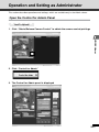
Access the Setting Menu
To configure each setting, first you need to access to the camera via a web browser.
To begin with, access to the camera’s top page (➞ P.x). For details of entering a user name and
a password, refer to page P.xiii.
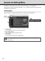
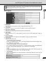
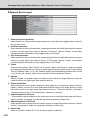
Setting Menu
You can access each setting page and the Admin viewer from the Setting Menu.
“VB-C60” is
displayed as
the model name.
12
12
2
12
12
1
3
1 to Top button
Click this button to move to the camera’s top page.
2 Open Viewer button
Click this button to open the Admin viewer.
3 Setting Menu
Click this button to move to each setting page.
Note
1-4
For security reasons, be sure to close the browser after you finish setting on the
setting pages.
Access the Setting Menu
Common Items
■ Apply Changes
When you change the settings on each setting page, the grayed-out “OK” button on the top right
Detailed Settings
of the page changes to blue.
Click “OK” to enable the changes.
Click “Clear” to reset the changes.
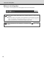
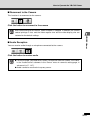
■ Setting Items That Require Reboot
An orange mark is indicated for each setting item that requires rebooting the camera to enable the
change.
When you change a setting item with the orange mark, the “OK” button displayed on the top right
of the setting page changes to “OK and Reboot”.
Click “OK and Reboot” to enable the change. The setting changes and then the camera reboots.
Click “Clear” to reset the changes.
Tip
● A dialog box appears to alert when clicking “OK” or “OK and Reboot” after changing
the network setting, in which the currently-used browser becomes unable to access
to the camera.
● If the above network setting is changed and so the viewer cannot reconnect to the
camera automatically, links to candidate URIs are displayed. However, you may
not be able to connect using the URI, as these are just candidate URIs. In such
case, try connecting from VB Initial Setup Tool.
1-5
Access the Setting Menu
■ Return to the Setting Menu
Click “to Menu” on the top right of each setting page to return to the Setting Menu.
● Do not open multiple setting pages when changing settings for a single camera
Note
settings.
● Do not use “Back” and “Forward” of the web browser to move between the setting
pages. The old page is displayed due to effects of caching, so the set values may
return to the older ones, or unintended changes may be made.
Detailed information for each setting item is available by clicking
Tip
1-6
column.
“HELP” in each
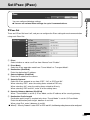
Set Administrator Password, LAN, IPv6 and DNS (Network)
You can configure following settings.
Detailed Settings
● Administrator Password
Setting the administrator password.
● LAN
Setting for items required for LAN connection such as IP address.
● IPv6
Setting for IPv6.
● DNS
Setting for the name server address, host name and DDNS.
● SNMP
Setting for SNMP.
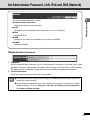
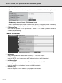
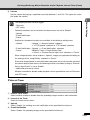
▼Administrator Password
12
12
1
12
12
2
1 Password
Set the administrator password. Up to 8 alphanumeric characters (including spaces and
printable characters) can be used. The factory default setting is “VB-C60”. Be sure to disconnect
the Admin viewer or VBAdmin Tools from the camera before changing the password.
2 Confirm Password
Enter the same password as above for confirmation.
Note
● For system security, make sure to change the administrator password, and not to
forget the new password.
● If you forget the password, press the camera’s reset switch to restore the factory
default setting (➞ P.5-15). However, note that all settings will be restored to
the factory default settings.
1-7
Set Administrator Password, LAN, IPv6 and DNS (Network)
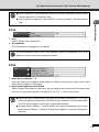
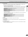
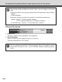
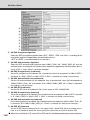
▼LAN
12
12
1
12
12
2
12
3
12
12
4
12
5
12
12
6
1 IP Address Setting
Select “Auto (DHCP)” or “Manual” as IP address setting method. If you select “Auto (DHCP)”,
values automatically retrieved from the DHCP server are used for “IP Address”, “Subnet Mask”,
and “Default Gateway Address”. If you select “Manual”, directly enter values according to the
environment.
2 IP Address
Enter the static IP address if you specify “Manual” in 1.
3 Subnet Mask
Set the subnet mask assigned to each network if you specify “Manual” in 1.
4 Default Gateway Address
Set the default gateway address if you specify “Manual” in 1. Be sure to set the address
when connecting the camera to a subnet other than the viewer.
5 LAN Interface
Select from “Auto”, “Full Duplex” and “Half Duplex”. Normally, use “Auto”.
6 Maximum Transmission Unit
Enter the maximum transmission unit size. Normally, there is no need to change this setting
from 1500.
Note
● Please consult with your network administrator for “IP address”, “Subnet Mask”,
and “Default Gateway Address”.
● If there are any errors in any of “IP address”, “Subnet Mask” or “Default Gateway
Address”, you may not be able to access the camera via the network. In this case,
use the VB Initial Setting Tool v4.0 (➞d Start Guide P.2-9) to configure the address
settings again.
● If you change the setting of “IP Address Setting”, “Subnet Mask”, “Default Gateway
Address”, “LAN Interface” or “Maximum Transmission Unit”, the currently-used
browser may become unable to access the camera. Be sure to read the note in the
“Setting Items That Require a Reboot” page, in advance (➞ P.1-42). It is also
recommended to read the note before changing settings of “IPv6” and “DNS”
(➞ P.1-9).
● When “Auto (DHCP)” is specified for “IP Address Setting”, the IP address may not
be correctly assigned if there is a router between the DHCP server and VB-C60. In
this case, specify “Manual” and assign a fixed IP address manually.
● When using IPv6, set “Maximum Transmission Unit” to 1280 or higher.
1-8
Set Administrator Password, LAN, IPv6 and DNS (Network)
● When using ADSL, the transmission efficiency may be increased by setting a lower
Tip
value for Maximum Transmission Unit.
● The IP address assigned by “Auto (DHCP)” can be confirmed in VB Initial Setting
Tool.
Detailed Settings
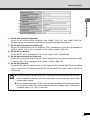
▼IPv6
12
12
1
12
2
12
1 IPv6
Select “Enable” when using IPv6.
2 IPv6 Address
The IPv6 address is displayed in the column.
Tip
▼DNS
In the environment where IPv6 is not available, nothing is displayed in the “IPv6
Address” column even when specifying “Enable”.
12
12
1
12
12
2
1 Name Server Address 1 - 2
Enter the name server address to be registered. When using only one name server, leave
Name Server Address 2 field blank.
2 Host Name Registration with DDNS
Select “Enable” and enter the host name. You can register the host name to the name server.
You can use up to 63 characters including A-Z, a-z, 0-9, -, ., for the host name.
Tip
● The host name is useful when using the VB-C60 with “Auto (DHCP)” (➞ P.1-8).
You must register the host name in the DNS server in advance. For more information
on DNS server settings, contact your system administrator.
● If Name Server Address 1 is not available, the camera automatically will access
Name Server Address 2. However, Name Server Address 2 must be registered in
advance.
1-9
Set Administrator Password, LAN, IPv6 and DNS (Network)
▼SNMP
12
12
1
12
2
12
3
12
12
4
12
5
1 SNMP
Select from “Disable” and “Enable”. Specify “Enable” if you need to reference camera’s
information from the SNMP manager.
2 Community Name
Enter the SNMP community name. For security reason, it is recommended to change the
default community name.
3 Administrator Contact Information
Enter the contact information of camera’s administrator, such as an e-mail address. The entered
information can be checked from the SNMP manager.
4 Administration Function Name
Enter the camera name used for administration. The entered name can be checked from the
SNMP manager. When it is blank, default value “VB-C60” is used.
5 Installation Location
Enter camera’s location information. The entered information can be checked from the SNMP
manager.
Tip
1-10
● The camera’s information is read-only from the SNMP Manager.
● Use the SNMP Manager in SNMP MIB2 (RFC1213 compatible).
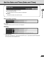
Set the Date and Time (Date and Time)
You can configure following settings.
● Setting
Setting for the date, time and time zone.
▼Current Date and Time
Detailed Settings
● Current Date and Time
The date and time set on the camera are displayed.
Date, Time
The date and time set on the camera are displayed.
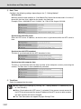
▼Setting
12
12
1
12
12
2
12
12
3
1 Setting Method
Select from “Set Manually”, “Synchronize with NTP server”, “Synchronize with NTP broadcast”
and “Synchronize with computer time”.
1-11
Set the Date and Time (Date and Time)
2 Date, Time
Configure the following settings depending on the 1 “Setting Method”.
Set manually
Manually enter the date and time in “Year/Month/Day” format for the date and in “hh:mm:ss”
format for the time. Use 2 digits for the month, day and time.
Example: Enter “2008/08/23” and “13:23:04” for 1:23:04 PM, August 23 2008.
Synchronize with NTP server
Enter the NTP server IP address, so that the time is synchronized with the NTP server’s
time.
Synchronize with NTP broadcast
The time is synchronized with the NTP broadcast’s time.
Synchronize with computer time
The time is synchronized with the date and time of the computer currently accessing the
camera. The time zone is also automatically selected.
3 Time Zone
Select the appropriate time zone.
Tip
1-12
● After applying the settings by clicking “OK”, “Setting Method” is automatically set
to “Set manually”.
● When “Synchronize with NTP server” is selected, if the camera cannot connect to
the NTP server because of the wrong IP address of the NTP server or other reasons,
the date and time will not be changed.
● The Time Zone does not support Daylight Savings Time.
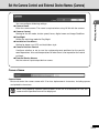
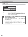
Set the Camera Control and External Device Names (Camera)
You can configure following settings.
Enter the camera name. The name is required when using VK-64 with the camera.
● Camera Control
Setting for the AF mode, shutter speed, focus, digital zoom and Image Stabilizer.
● Day/Night
Select the switching mode for Day/Night.
● Installation Conditions
Detailed Settings
● Camera Name
Setting for dome use, LED and installation style.
● Camera Position Control
Configure whether or not to use the registered preset positions for the pan/tilt/
zoom operations. Also set the operations of when there is no request for the control
privilege.
● External Device Names
Set the external input/output device names.
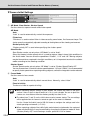
Camera Name
Camera Name
Be sure to enter the camera name with 15 or less alphanumeric characters, including spaces
and printable characters.
Tip
When using optional network video recorder VK-64/VK-16 or bandled VK-Lite, the
camera name specified here will be displayed.
1-13
Set the Camera Control and External Device Names (Camera)
▼Camera Initial Settings
1
1
1
1
2
1
1 AE Mode, Slow Shutter, Shutter Speed
Set the camera’s exposure mode and shutter speed.
AE Mode
Auto
“Auto” is used to automatically control the exposure.
Flickerless
“Flickerless” is used to reduce flicker in video caused by some factors, like fluorescent lamps. The
shutter speed is automatically adjusted according to the brightness of the shooting environment.
Shutter-priority AE
“Shutter-priority AE” is used when specifying the shutter speed.
Slow Shutter
Slow Shutter can be set only when “AE Mode” is set to “Auto”.
Select the slowest shutter speed, which is used to capture video in lower light conditions in
the “Auto” mode. You can select the speed from “Disable”, “1/15” and “1/8”. Moving subjects
may be blurred when captured in low light conditions, so it is important to select the suitable
mode according to the shooting condition.
Shutter Speed
Shutter Speed can be set only when “AE Mode” is set to “Shutter-Speed Priority AE”.
You can choose from 12 levels of shutter speed between “1/8” and “1/8000”. It is recommended
to specify faster speed when capturing moving subjects, so that the image blur can be reduced.
2 Focus Mode
Set the camera’s focus mode.
Auto
“Auto” is used to automatically obtain correct focus. Normally, select “Auto”.
Fixed at infinity
The focus is fixed at a point of infinity.
Note
● When monitoring subjects through a glass window, the camera may focus on the glass
surface if there is dust or drop of water on it. So, in such situation, be sure to place the
camera at a close distance from the window, possibly less than 30 cm.
● The above item 1 and 2 are the initial values used at camera startup. The new settings
will be applied when the camera is turned on again or the camera is rebooted.
Use the “Control for Admin” panel of VB-C60 viewer to configure the settings used in the
actual operating environment (➞ P.3-21).
● When capturing subjects like traffic lights and electronic signboards, the captured
video may be blinking. It may be reduced by changing the exposure mode to “Auto
(Shutter-priority AE)” and choosing a shutter speed of 1/100 or slower.
1-14
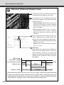
Set the Camera Control and External Device Names (Camera)
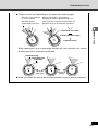
● The camera may have difficulty focusing automatically on subjects of the type
Tip
shown below.
Detailed Settings
Subjects with little or
no contrast (e.g. a
white wall)
Angled subjects
Highly reflective
subjects
Subjects that consist
entirely of oblique or
horizontal lines or stripes
Insubstantial
subjects such as
flames or smoke
Subjects seen
through glass
Quickly moving
subjects
Night views or
dark places
Far and near subjects
in the same frame
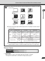
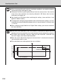
● The focusing range (approx) differs depend on the “Day/Night” and other settings
as shown below.
Day/Night setting
Auto
Day mode
Night mode
Dome
Infrared lamp
Wide end
Tele end
Wide end
Tele end
Not used
None
0.3m∼∞
1.5m∼∞
0.5m∼∞
1.8m∼∞
Used
None
Not used
Yes
0.5m∼∞
1.8m∼∞
Used
Yes
0.5m∼∞
2.4m∼∞
Fixed at infinity
2.1m∼∞
2.4m∼∞
None
Point of infinity
Yes
Point of infinity
Note) The camera may be out of focus.
● It is recommended to set “Focus Mode” to “Fixed at infinity” to capture video of lowcontrast subjects, of which it is difficult to obtain correct focus, e.g. night scene.
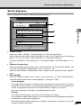
▼Camera Control
12
12
1
12
12
2
1 Digital Zoom
Select whether or not to use the digital zoom from “Disable” or “Enable”.
* The higher the zoom factor is, the lower the image quality may be.
1-15
Set the Camera Control and External Device Names (Camera)
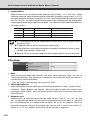
2 Image Stabilizer
Select whether or not to activate Image Stabilizer from “Disable”, “On1” and “On2”. Image
Stabilizer effectively works to compensate for image blur caused by camera shake. If “On1” is
not strong enough to correct the image blur, try “On2”. While Image Stabilizer is being activated
with “On1” or “On2”, the viewing angle may be narrower and the image quality may be degraded,
comparing with when Image stabilizer is disabled. This is because of the stabilization process,
not camera failure.
Blur Level
_
Ratio of viewing angle
No. of effective pixels
100%
Approx. 310,000 pixels
On1
Small
83%
Approx. 210,000 pixels
On2
Large
50%
Approx. 80,000 pixels
Disable
Note
● It is recommended to set the image capture size to “320 x 240” or smaller, while
specifying “On2”.
● IS does not work to correct vibration of a subject itself.
● Image Stabilizer cannot correct image blur caused by instantaneous shake or large
vibration that exceeds a certain level.
● Refer to P.3-20, for note on viewer use while Image Stabilizer is being activated.
▼Day/Night
12
12
1
12
2
12
12
3
1 Mode
Select the switching mode from “Manual” and “Auto”. When specifying “Auto”, you can set
“Switching Brightness” and “Response” according to the environment where the camera is
installed or the switching condition.
* If you are using an infrared lamp, you cannot use “Auto”.
2 Switching Brightness
Select the brightness level to switch day mode and night mode from “Darker”, “Slightly Darker”,
“Standard”, “Slightly Brighter” and “Brighter”. When you prefer to shoot color video as much
as possible, select “Darker”. When you prefer to reduce noise even in black and white video,
select “Brighter”.
3 Response (sec.)
Select the time, at which day mode and night mode switches, from “5”, “10”, “20”, “30” and
“60”. The day and night mode are switched when the brightness set in the above 2, maintains
for a set period of time. It is recommended to specify “30” or “60” for situations, where the
brightness frequently changes, for example, light sources pass in front of the camera. Or,
specify “5” or “10” for situations, where there are few changes in brightness.
1-16
Set the Camera Control and External Device Names (Camera)
● Operation of the day/night switching function should be tested thoroughly before
Note
using “Day/Night” in the “Auto” mode.
● When using “Day/Night” in the “Auto” mode, “AE Mode” should be set to “Auto” or
Flickerless” (➞ P.3-25).
● While using “Day/Night” in the “Auto” mode, the IR cut filter may be inserted and
removed several times, at the time of switching day mode and night mode. In the
meanwhile, Pan, Tilt, Zoom and Manual focus do not operate.
Detailed Settings
● When using the camera with IR light, “Day/Night” should be set to “Manual”. IR
light cannot be used in the “Auto” mode.
▼Installation Conditions
12
12
1
12
12
2
12
12
3
1 Dome
Select whether or not to use a dome. When you use the camera with a dome housing, select “Used”.
2 LED Setting
Select whether or not to light the LED on camera’s head arm from “Turn On” and “Turn Off”.
Select “Turn OFF” when the LED light is not needed or it can interfere monitoring, for example,
when you use the camera with an optional indoor dome housing (VB-RD51S-C/S) or when
reflected LED lights may be gotten into the shooting frame.
3 Mount
Select the camera mount type. The factory default setting is Inverted.
Tip
● Even when “LED Setting” is set to “Turn off”, the LED will turn on once when the
camera is started.
● The image for the Inverted “Mount” type shows the conditions with the cover for a
ceiling mount (The ceiling mount cover is option).
▼Camera Position Control
12
1
12
12
2
1 Restricted to Presets
Select whether or not to restrict the camera control to presets from “No Restriction” and “Preset
Only”. When “Preset Only” is selected, the camera control is restricted to preset angles only
for all users except the administrator.
1-17
Set the Camera Control and External Device Names (Camera)
2 Camera Position without Control
Select whether or not to move the camera’s direction to the home position when nobody has
the control privilege. Specify “Return to Home Position” so that the camera automatically
changes its direction to the home position. Before using this function, you need to set the
camera’s home position using VBAdmin Tool (➞ P.2-18).
▼External Input Device 1 - 2/External Output Device 1 - 2
External Input Device/External Output Device - Device Name
To distinguish between connected external devices, be sure to set a device name with up to 15
ASCII characters (including blank and printable characters) excluding double quote “ " ”.
Tip
1-18
When you are using the Admin viewer, optional network video recorder
VK-64/VK-16, or bundled VK-Lite, the device name specified here is displayed.
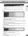
Set the Image Size, Quality and Frame Rate (Image)
You can configure following settings.
Configure the image quality, size and maximum frame rate for JPEG images.
● MPEG-4
Configure the image quality, size and capture frame rate for MPEG-4 video.
▼JPEG
Detailed Settings
● JPEG
12
12
1
12
12
2
12
12
3
12
4
1 Image Quality
Select the image transmission quality for each image size in JPEG from 1 - 5 (in 5 levels).
The higher the value, the higher the image quality.
2 Image Size: Image Transmission
Select the image size used when transmitting images from “160x120”, “320x240” and
“640x480”. The set image size is used as a default image size for transmitting images to
viewers.
3 Maximum Frame Rate: Image Transmission
Reduce the viewer load by limiting the maximum frame rate for transmitting images per second.
The maximum value is 30 fps. Enter a value between 0.1 and 30. 0.
4 Image Size: Upload
Select the image size for image upload from “160x120”, “320x240” and “640x480”. For
information on upload settings, refer to P.1-21.
▼MPEG-4
12
12
1
12
12
2
12
3
1 Video Quality
Select the video quality for MPEG-4 video from 1 - 5 (in 5 levels).
The higher the value, the higher the video quality.
2 Video Size
Select the video size for transmission from “320x240” and “640x480”.
3 Capture Frame Rate
Select the capture frame rate from “10”, “15” and “30”.
1-19
Set the Image Size, Quality and Frame Rate (Image)
● Higher image size or quality results in a larger data size per frame and a heavier
Note
network load.
JPEG
: The frame rate may decrease.
MPEG-4 : Video may be interrupted temporarily.
● The data volume may become large according to the type or amount of movements
of subjects. Set the image size smaller or set the image quality lower, in conditions,
where the frame rate continues decreasing for a long time.
● If you are using optional network video recorder VK-64/VK-16 or bundled VK-Lite,
the image size and quality settings affect the required hard disk space for recording.
1-20
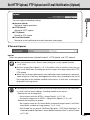
Set HTTP Upload, FTP Upload and E-mail Notification (Upload)
Setting for upload operations.
● HTTP Upload
Setting for HTTP upload.
● FTP Upload
Setting for FTP upload.
● E-mail Notification
Detailed Settings
You can configure following settings.
● General Upload
Setting for e-mail notification of event information and images.
▼General Upload
Upload
Select the upload method from “Upload Disabled”, “HTTP Upload” and “FTP Upload”.
Note
● You also need to set the “Event” menu settings to use the upload function
(➞ P.1-29).
● Set the “Image Size: Upload” (➞ P.1-19) to 320 x 240 or smaller, when you use
both e-mail notification including text and an image, and image upload by HTTP/
FTP upload.
● When you set image upload and e-mail notification to be continuously carried out,
some images or e-mail may be dropped and not be sent, according to the size of
the image data or the network condition to the server. In that case, a message is
displayed in the log events.
● Following tips are effective to reduce the load of image upload and e-mail notification.
Tip
It is also useful to check settings, including network to the server.
• Reduce the size of image files
- Set a smaller value for JPEG > “Image Quality” (➞ P.1-19).
- Set smaller image size in JEPG > “Image Size: Upload” (➞ P.1-19).
• Reduce the frequency of upload
- Set a smaller value for “Pre-event Buffer (number of image frames)” and “Postevent Buffer (number of image frames)” (➞ P. 1-29).
- Set “Disable” for any one of “ON Event Operation”, “OFF Event Operation”, or
“Continuous Motion Operation”, when “Motion Detection Event” is set to “Enable”
(➞ P.1-30).
1-21
Set HTTP Upload, FTP Upload and E-mail Notification (Upload)
- Set “Disable” for either of “ON Event Operation” or “OFF Event Operation”,
when “External Device Input Event” is set to “Enable” (➞ P. 1-32).
- Select a longer interval for “Interval of the Timer”, when “Interval Timer Event”
is set to “Enable” (➞ P.1-33).
• Reduce the frequency of e-mail notification
- Set “Disable” for any one of “ON Event Operation”, “OFF Event Operation”, or
“Continuous Motion Operation”, when “Motion Detection Event” is set to “Enable”
(➞ P.1-30).
- Set “Disable” for either of “ON Event Operation” or “OFF Event Operation”,
when “External Device Input Event” is set to “Enable” (➞ P. 1-32).
- Select a longer interval for “Interval of the Timer”, when “Interval Timer Event”
is set to “Enable” (➞ P.1-33).
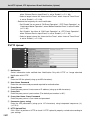
▼HTTP Upload12
12
1
12
2
12
12
3
12
12
4
12
5
12
12
6
12
12
7
12
8
1 Notification
Select information to be notified from “Notification Only with HTTP” or “Image attached
Notification with HTTP”.
2 URI
Enter the URI for upload (using up to 255 characters).
3 User Name, Password
Enter the user name and password required for authentication.
4 Proxy Server
Enter the proxy server’s host name or IP address (using up to 63 characters).
5 Proxy Port
Enter the proxy server’s port number (The default port number is “80”).
6 Proxy User Name, Proxy Password
Enter the proxy server’s user name and password.
7 Parameter (query string)
Enter the URI parameters (using up to 127 characters) using interpreted sequences (%)
(➞ P.5-2).
8 HTTP Upload Test
Click “Exec” to perform a HTTP to check if HTTP upload is properly carried out according to
your settings.
1-22
Set HTTP Upload, FTP Upload and E-mail Notification (Upload)
Enter “Proxy Server”, “Proxy Port”, “Proxy User Name” and “Proxy Password” when
Note
connecting to the camera via a proxy server.
12
12
1
12
12
2
12
12
3
12
12
4
12
152
12
6
12
7
Detailed Settings
▼FTP Upload
1 Notification
The information to be notified is set to “Image data upload with FTP”.
2 FTP Server
Enter the FTP server’s host name or IP address (using up to 63 characters).
3 User Name, Password
Enter the user name and password required for authentication.
4 PASV Mode
When uploading via FTP, select whether or not to use the PASV mode from “Enable” or
“Disable”.
5 File Upload Path
Enter a remote path for image files to be upload to (using up to 255 characters).
6 File Naming
Select the file naming rule.
“Year month day hour second ms”
Images are uploaded with file name “{year}{month}{day}{hour}{minute}{second}{ms}.jpg”.
(e.g.: 20080123112122000.jpg)
“Year month day folder / hour minute second ms”
First, a folder named “{year}{month}{day}” is created, and then images are uploaded with
file name “{hour}{minute}{second}.jpg”. (e.g.: 20080123/112122000.jpg)
“Loop”
Images are uploaded with a file name starting from the number “0000” up to the number set
in “Maximum Number of Loops”. (e.g.: 0000.jpg, 0001.jpg)
“User settings”
Images are uploaded with a file name specified in “Subdirectory Name to Create” and “File
Name to Create”.
1-23
Set HTTP Upload, FTP Upload and E-mail Notification (Upload)
Maximum Number of Loops
Enter the maximum number of loops between 0 and 9999 when “File Naming” is set to
“Loop”.
Subdirectory Name to Create, File Name to Create
Enter a subdirectory name and file name to create (up to 127 characters) when “File Naming”
is set to “User Setting”, using interpreted sequences (%) (➞ P.5-2).
7 FTP Upload Test
Click “Exec” to perform an FTP upload test to check if FTP upload is properly carried out
according to your settings.
▼E-mail Notification
12
12
1
12
12
2
12
3
12
12
4
12
5
12
12
6
12
7
12
12
8
12
12
9
1 Notification
Select information to be notified from “Text only” or “Text with Image”.
2 Mail Server Name
Enter the SMTP server’s host name or IP address (using up to 63 characters).
3 Mail Server Port
Enter the SMTP server’s port number (The default port number is “25”).
4 Sender (From)
Enter the sender’s e-mail address (using up to 63 characters).
5 Recipient (To)
Enter the recipient’s e-mail address (using up to 63 characters).
1-24
Set HTTP Upload, FTP Upload and E-mail Notification (Upload)
6 Authentication
Select the mail authentication method from “None”, “POP before SMTP” and “SMTP-AUTH”,
according to the authentication method of the destination SMTP server.
Detailed Settings
User Name, Password, POP Server
When the mail authentication method is set to “POP before SMTP”, enter the user name
and password required for authentication, and the POP server’s host name or IP address.
User Name, Password
When the mail authentication method is set to “SMTP-AUTH”, enter the user name and
password required for authentication.
7 Subject
Enter a subject for e-mail notification (using up to 31 characters).
8 Message Body
Enter the message (text) of e-mail (using up to 255 characters), using interpreted sequences
(%) (➞ P.5-2).
9 E-mail Notification Test
Click “Exec” to perform an e-mail notification test to check if e-mail notification is properly
carried out according to your settings.
1-25
Set Up the Image, Audio and HTTP Servers (Server)
You can configure the following settings.
● Image Server
Setting for image distribution from the camera.
● Audio Server
Setting for audio transmission and reception.
● HTTP Server
Setting for the HTTP port and Web page distribution.
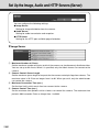
▼Image Server
12
1
12
12
2
12
3
12
12
4
1 Maximum Number of Clients
Set the maximum number of clients, to which the camera can simultaneously distribute video.
You can set up to 30 clients. When 0 is specified, only the Admin viewer can connect to the
camera.
2 Camera Control Queue Length
Set the maximum queue length of requests for the camera control privilege from viewers. The
maximum value is 30. Enter an integer from 0 to 30. When you set 0, only the administrator
can control the camera.
3 Maximum Connection Time (sec.)
Set the time limit in which each client can connect to the camera.
4 Camera Control Time (sec.)
Set the maximum time period in which viewers can control the camera. The maximum time
period is 3600 seconds. Enter an integer from 1 to 3600.
1-26
Set Up the Image, Audio and HTTP Servers (Server)
▼Audio Server
1 Audio Transmission from the Camera
Specify “Enable” for transmitting audio from a microphone connecting to the camera to
VB-C60 viewer.
Detailed Settings
12
1
12
12
2
12
12
3
12
4
12
5
12
12
6
12
12
7
2 Input Volume
Set the volume on the microphone between 1 and 100. The higher the value, the louder the
microphone’s output volume.
3 Voice Activity Detection
Specify “Enable”, so that the data size for audio transmission is temporarily reduced while the
server is not detecting any audio input. It enables to reduce network load.
4 Audio Reception from Viewer
Specify “Enable” for outputting audio from optional VK viewers or bundled VK-Lite viewer
through speakers connected with the camera.
5 Output Volume
Set the volume on the speakers, between 1 and 100. The higher the value, the louder the
speaker’s volume.
6 Echo Canceller
Specify “Enable” for removing echo caused in the microphone and speakers.
7 Audio Input
Select the microphone input mode from “Line In”, “Microphone In (dynamic microphone)” and
“Microphone In (condenser microphone)”.
・Audio Transmission
・Input Volume
・Voice Activity Detection
・Echo Canceller
・Audio Reception
・Output Volume
1-27
Set Up the Image, Audio and HTTP Servers (Server)
● Switch between Line In and Microphone In in the setting page according to the
Note
specifications of the microphone you use (➞ P.1-27).
Be sure to use the correct settings to avoid damaging to the camera and microphone.
● Volume and audio quality may vary depending on the characteristics of the
microphone.
● Use the VK-Lite viewer to send audio via VB-C60’s audio output terminal. It cannot
be sent from the VB-C60 viewer (➞d Start Guide P.1-8).
● Use a speaker with amprifier to connect to the camera (➞d Start Guide P.3-7).
● When “Echo Canceller” is set to “Enable”, audio quality and volume may be affected.
Use this function according to the environment where you install and how you use
the VB-C60.
● Before using audio transmission function, be sure to read “Usage Notice of Audio”
carefully (➞d Start Guide P.xiv).
▼HTTP Server
1
1
1
1
2
1
1 HTTP Port
Set the HTTP port number to 80 or between 1024 and 65535.
Normally use 80 (factory default setting).
2 Global Address for the Web Page
Enter the global address and the port number to assign a fixed global address to the camera
(➞ P.4-10) using router’s NAT function. When “IP Address” is selected, enter the IP address
specified in the “IP Address” field. When “Host Name” is selected, enter the host name specified
in “DNS” in “Network”. Perform any necessary settings in “DNS” (➞ P.1-9).
Note
● If you change the setting of “HTTP Port”, the currently-used browser may become
unable to access the camera. Be sure to read the note in the “Setting Items That
Require a Reboot” page (➞ P.1-43), in advance.
● When selecting “IP Address” in “Global address for the Web page”, be sure to set
both “IP Address (global address for the Web page)” and “Port Number (global
address for the Web page)”. When selecting “Host Name”, be sure to set “DNS” ➞
“Host Name” in “Network”, too.
1-28
Set Image Buffering, Motion Detection, Audio Playback, Interval Timer (Event)
Setting for buffering images.
● Motion Detection
Setting for operations while motion detection is being activated.
● External Device Input
Setting for operations during external device input events.
● Interval Timer
Detailed Settings
You can configure following settings.
● Image Buffer
Setting for interval timer for e-mail notification and upload operations.
● Sound Clip Upload
Setting for audio files to be registered.
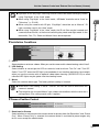
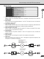
▼Image Buffer
12
12
1
12
12
2
12
12
3
1 Frame Rate
Set the frame rate used when temporarily buffering images in the camera.
2 Pre-event Buffer (number of image frames)
Set the number of images to be buffered, which were captured prior to each event.
3 Post-event Buffer (number of image frames)
Set the number of images to be buffered, which were captured after each event.
Note
● The maximum size of image buffering is approximately 4 MB.
When you set a smaller image size, “Frame Rate”, “Pre-event Buffer”, or “Postevent Buffer” may not be carried out as you set (➞ P.1-21).
● When image buffering is not carried out as you set, a message is displayed in the
log events.
Make sure that there is no log event occurring before use the function (➞ P.1-21).
1-29
Set Image Buffering, Motion Detection, Audio Playback, Interval Timer (Event)
▼Motion Detection
12
12
1
12
2
12
3
12
4
12
5
12
12
6
12
7
12
8
12
9
12
!0
12
12
!1
12
!2
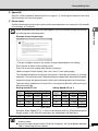
1 Motion Detection Event
Whether motion detection is enabled or disabled is indicated. You can switch between enabled
or disabled using “Motion Detection Setting Tool” of VBAdmin Tools (➞ P.2-27).
2 ON Event Operation
Select whether or not to activate image upload and e-mail notification when the camera detects
motion (=ON event). Specify “Enable” to activate those functions when the camera detects
motion.
3 OFF Event Operation
Select whether or not to activate image upload and e-mail notification when the camera finishes
detecting motion (=OFF event). Specify “Enable” to activate those functions when the camera
finishes detecting motion.
4 Continuous Motion Operation
Select whether or not to activate image upload and e-mail notification during motion detection.
Specify “Enable” to activate those functions while the camera is detecting motion.
5 Upload
Specify “Enable” to upload images according to the setting for image buffering, when the
camera detects motion. To use this function, you also need to configure settings of the “General
Upload” submenu and the “HTTP Upload” or the “FTP Upload” submenu in “Upload”.
6 E-mail Notification
Specify “Enable” to send an e-mail notification when the camera detects motion. To use this
function, you also need to configure settings of the “E-mail Notification” submenu in “Upload”.
7 Audio Playback at ON Event
Select whether or not to activate audio play when the camera detects motion (=ON event).
Specify “Enable” for playing an audio file, specified in following “Sound Clip”, when the camera
detects motion (=ON event).
8 Audio Playback at OFF Event
Select whether or not to play audio when the camera finishes detecting motion (=OFF event).
Specify “Enable” for playing an audio file, specified in following “Sound Clip”, when the camera
finishes detecting motion (=OFF event).
9 Sound Clip
Select an audio file. Refer to P. 1-34, for how to register audio files.
1-30
Set Image Buffering, Motion Detection, Audio Playback, Interval Timer (Event)
!0 Volume
Set the volume for playing a specified sound clip between 1 and 100. The higher the value, the
louder the volume.
!2 Maximum Tracking Time (sec.)
Set the time to continue automatic tracking.
The motion detection and external device output functions cannot be used together.
Detailed Settings
!1 Automatic Tracking at ON Event
Select whether to automatically change the camera direction toward a subject during detecting
motion (=ON event). Specify “Enable” so that the camera automatically changes its direction
toward a moving subject while the camera is detecting the motion.
Note
● The following events can be a trigger in motion detection.
Tip
• ON Event
• OFF Event
• Continuous Motion (Time of motion detection)
Following functions can be set when the above items are set to “Enable”.
• Upload
• E-mail notification
Settings for upload and e-mail notification are available in the following setting
menu.
• Upload
: “Upload” ➞ “General Upload” submenu
➞ “HTTP Upload” submenu or “FTP Upload” submenu
• E-mail Notification: “Upload” ➞ “E-mail Notification” submenu
When image upload is set to enable in “Upload”, images are uploaded according
to the settings of the “Image Buffer” submenu in “Event”.
Even when neither image upload nor e-mail notification is set to be activated for
motion detection events, the following function is available as long as “Motion
Detection Event” is set to “Enable”.
• Notification of event to clients
Whether to enable or disable audio playback can be specified for each of ON
event and OFF event.
● For notes on motion detection use, refer to Start Guide P.xiv.
1-31
Set Image Buffering, Motion Detection, Audio Playback, Interval Timer (Event)
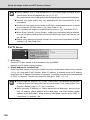
▼External Device Input
1
1
1
1
1
1
1
1
1
1
1
1
1
1
2
3
4
5
6
7
8
9
!0
1 External Device Input Event
Select whether or not to enable image upload and e-mail notification triggered by an external
device input event.
2 ON Event Operation
Select whether or not to activate preset, image upload and e-mail notification when the camera
receives an input signal from external devices (=ON event). Specify “Enable” so that those
functions become activated by being triggered by an ON event.
3 OFF Event Operation
Select whether or not to activate preset, image upload and e-mail notification when the camera
receives no input signal from external devices (=OFF event). Specify “Enable” so that those
functions become activated by being triggered by an OFF event.
4 Preset
Select preset positions from “Preset1” to “Preset20”. When controlling the camera according
to events from external devices, first you need to register preset positions using “Preset Setting
Tool” of “VBAdmin Tools” (➞ P.2-18), and then specify the corresponding positions from “Preset
1” to “Present 20”. Specify “None” when you don’t need to control the camera.
5 Upload
Specify “Enable” to upload images according to the setting for image buffering, when the
camera receives an input signal from external devices.
6 E-mail Notification
Select whether or not to upload images by being trigger by an input from external devices.
Specify “Enable” to send an e-mail notification based on settings for image buffering, when
the camera receives an input signal from external devices. To use this function, you need to
configure settings of the “E-mail Notification” submenu in “Upload”.
7 Audio Playback at ON Event
Select whether to play audio when the camera receives an input signal from external devices.
Specify “Enable” for playing an audio file registered in following “Sound Clip”.
8 Audio Playback at OFF Event
Select whether to play audio when the camera receives no input from external devices. Specify
“Enable” for playing an audio file registered in following “Sound Clip”.
9 Sound Clip
Select an audio file. Refer to P.1-34, for how to register audio files.
1-32
Set Image Buffering, Motion Detection, Audio Playback, Interval Timer (Event)
0 Volume
Set the volume for playing a specified sound clip between 1 and 100. The higher the value,
the louder the volume.
Tip
• ON event
• OFF event
Following functions can be set when the above items are set to “Enable”.
• Upload
• E-mail Notification
Detailed Settings
The following events can be a trigger.
• Preset
Settings for the above functions are available in the following setting menu.
• Upload
: “Upload” ➞ “General Upload” submenu
➞ “HTTP Upload” submenu or “FTP Upload” submenu
• E-mail Notification : “Upload” ➞ “E-mail Notification” submenu
• Preset
: VBAdmin Tools ➞ Preset Setting Tool
➞ “Event” ➞ “External Device Input 1 or2” submenu ➞ “Preset”
When image upload is set to enable in “Upload”, images are uploaded according to
the settings of the “Image Buffer” submenu in “Event”.
Even when image upload, e-mail notification and preset are all not set to be activated
for external device input events, the following function is available as long as “External
Device Input Event” is set to “Enable”.
• Notification of event to clients
Whether to enable or disable audio playback can be specified for each of ON event
and OFF event.
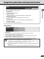
▼Interval Timer
12
12
1
12
2
12
12
3
12
4
1 Interval Timer Event
Select whether enable or disable timer for uploading images and/or e-mail notification.
2 Interval of the Timer
Select the interval of the timer.
3 Upload
Select “Enable” for sending an e-mail notification at the specified time intervals.
4 E-mail Notification
Select “Enable” for uploading images at the specified time intervals.
1-33
Set Image Buffering, Motion Detection, Audio Playback, Interval Timer (Event)
Interval timer events according to “Interval Timer” can be a trigger in the interval
Tip
timer.
Following functions can be set when upload and e-mail notification is set to “Enable”.
• Upload
• E-mail notification
Settings for the above functions are available in the following setting menu.
• Upload: “Upload” ➞ “General Upload” submenu
➞ “HTTP Upload” submenu or “FTP Upload” submenu
• E-mail Notification: “Upload” ➞ “E-mail Notification” submenu
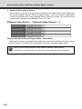
▼Sound Clip Upload
12
12
1
12
12
2
1 Browse File
Specify an audio file to be uploaded as sound playback.
2 Sound Clip Name
Name the audio file to be registered (up to 15 characters).
To delete registered files, click “Delete”.
Tip
1-34
You can register only audio files, of which playback time is 20 seconds or shorter,
and of which file format is “wav.” (µ-law, PCM 8 bits, 8000Hz sampling frequency,
mono).
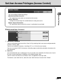
Set User Access Privileges (Access Control)
For registering users who can connect to the camera.
● User Authority
Configure user privileges for authorized users and guest users.
● Host Access Restriction
For specifying hosts from which access is authorized or restricted.
Detailed Settings
You can configure following settings.
● Authorized User Account
▼Authorized User Account
12
12
1
12
2
12
1 User Name, Password
You can add authorized users to the “User List” by entering their user names and passwords
and then clicking “Add”.
You can use up to 8 characters, including A-Z, a-z, 0-9 for the user names.
You can use up to 8 ASCII characters (including spaces and other printable characters) for
the passwords.
2 User List
A list of authorized users is displayed. You can set the user authorities for those users. Up to
50 users can be registered, in addition to the Administrator (root).
You can switch the sort the list of these users using on the right side.
To remove a user from the list, select the user from the User List and click “Delete”.
1-35
Set User Access Privileges (Access Control)
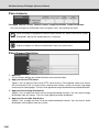
▼User Authority
Privileged Camera Control, Camera Control, Image Distribution, Audio Distribution
Set user privileges for authorized users and guest users, by checking the items.
Note
When recording using optional network video recorder VK, make sure that the “Audio
Distribution” box for the authorized user is checked.
Higher privileges can be set to authorized users over guest users.
Tip
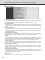
▼Host Access Restriction
12
12
1
12
12
2
12
3
12
12
4
1 Host List
The list shows settings for authorized hosts and restricted hosts.
2 Apply the list to HTTP Server
Specify “Yes” to apply the host list to HTTP server access. Once applied, some user access
will be restricted, such as access to the camera from viewers, access to camera's top page
and access to setting pages. The list is also applied to image distribution and audio distribution.
3 Apply the list to Image Distribution
Specify “Yes” to apply the host list to the image distribution function. You can restrict image
distribution from any viewer. The list is also applied to audio distribution.
4 Apply the list to Audio Distribution
Specify “Yes” to apply the host list to the audio distribution function. You can restrict audio
distribution and reception from any viewer.
1-36
Set User Access Privileges (Access Control)
● If there is no Host List, access is permitted to all hosts.
Note
● If the Host List that prohibits access for all hosts is applied, the host restriction
function will be disabled and access is permitted to all hosts.
● To prohibit access over the HTTP connection via a proxy server, the address of
the setting pages may be prohibited, and you may have to restore the factory
default settings.
● When using the host access control, you cannot connect to the VB-C60 via IPv6.
● If you change the setting of “Host List” or “Apply the list to HTTP Server”, the
currently-used browser may become unable to access the camera. Be sure to
Detailed Settings
the proxy server must be set.
● When the Host Access Restriction settings are configured incorrectly, access to
read the note in the “Setting Items That Require a Reboot” page (➞ P.1-43), in
advance.
1-37
Set User Access Privileges (Access Control)
Tip
The Host Restriction function is to restrict hosts, in which viewers and other client
applications are running. Access restriction is available with a list including single or
multiple entries, described in the following format.
Listing Format
“ ! ” addr “ -addr2 ”
● “addr” is written in the standard IP address format.
● Because the IP addresses in “addr” and “addr2” define the range of IP addresses,
if an IP address A is higher than “addr” and lower than “addr2”, the IP address A is
included in the addr-addr2 range. The addr2 parameter can be omitted, in which
case it is taken to be the same value as addr.
● If the entry begins with “!”, then access will be denied. If not, access will be authorized.
● If an address of host corresponds to more than one entry, the settings for the first
corresponding entry from the top of the Host List are used for determining whether
access is authorized or restricted. Therefore, note that in the examples 3 to 5
given below the entry of addresses to be authorized must be specified before the
addresses to be restricted.
● Redundant or contradictory entries included in the list are automatically deleted.
● If the given address does not belong to any of the entries, access is authorized.
Example 1: To prohibit access from a host
!172.20.0.10
Access from the host with an IP address of 172.20.0.10 is prohibited.
Example 2: To prohibit access from hosts in a given address range
!172.20.0.0-172.20.0.20
Access from hosts with IP addresses from 172.20.0.0 to 172.20.0.20 is prohibited.
Example 3: To authorize access from hosts in a given address range while
prohibiting access from other hosts
172.20.0.10-172.20.0.12
!0.0.0.0-255.255.255.0
Access is only authorized from hosts with IP addresses from 172.20.0.10 to
172.20.0.12 is prohibited.
Example 4: To prohibit access from hosts in a given address range while
permitting access from one host within that range
172.20.0.10
!172.20.0.0-172.20.0.20
Access from hosts with IP addresses from 172.20.0.0 to 172.20.0.20 is prohibited,
except for the host at 172.20.0.10, from which access is permitted.
Example 5: To prohibit access from hosts in a given address range while
permitting access from a range of hosts within that range
172.20.0.10-172.20.0.15
!172.20.0.0-172.20.0.20
Access from hosts with IP addresses from 172.20.0.0 to 172.20.0.20 is prohibited,
except for the hosts with addresses between 172.20.0.10 and 172.20.0.15, from which
access is permitted.
1-38
Set IPsec (IPsec)
▼IPsec Set
There are 5 IPsec Set from 1 to 5, and you can configure the IPsec settings for each communication
using each IPsec Set.
12
12
1
12
12
2
12
3
12
12
4
12
12
5
12
6
12
12
7
Detailed Settings
You can configure following settings.
● You can set various IPsec settings for up to 5 communications.
1 IPsec
Select whether or not to use IPsec from “Manual” and “Disable”.
2 IPsec Mode
Select the IPsec operation mode from “Tunnel Mode” or “Transport Mode”.
3 Destination (IPv4/IPv6)
Enter the destination IP address.
4 Source Address (IPv4/IPv6)
Enter the IP address of the source.
5 Security Protocol
Select the IPsec protocol to use from “ESP”, “AH” or “ESP and AH”.
When selecting “ESP”, enter the setting items related to ESP only.
When selecting “AH”, enter the setting items related to AH only.
When selecting “ESP and AH”, enter all of the setting items.
6 Security Gateway Address (IPv4/IPv6)
When “Tunnel Mode” is set for 2 IPsec Mode, set the IP address of the security gateway.
7 Destination Prefix Length
Destination prefix length is required only when “Tunnel Mode” is set for 2 IPsec Mode.
Enter the destination prefix length, between 0 and 128.
When using IPv4, enter it between 0 and 32.
■ When 5 “Security Protocol” is set to “ESP” or “ESP and AH”, the following setting items must be configured.
1-39
Set IPsec (IPsec)
12
12
8
12
12
9
12
12
!0
12
12
!1
12
12
!2
12
!3
12
12
12
!4
12
!5
12
8 SA ESP Encryption Algorithm
Select the ESP encryption algorithm from “AES”, “3DES”, “DES” and “NULL” according to the
encryption algorithm supported by the destination device.
“AES” or “3DES” is recommended to use normally.
9 SA ESP Authentication Algorithm
Select the ESP authentication algorithm from “HMAC_SHA1_96”, “HMAC_MD5_96” and “No
Authentication” according to the authentication algorithm supported by the destination device.
If only “ESP” is used, “None” cannot be selected.
0 SA ESP Encryption Key (outbound)
Set the SA encryption key for outbound. Set a hexadecimal value that corresponds to 128bit if “AES” is
selected in 8, 192bit if “3DES” or “64bit if “DES”. If “NULL” is selected, this setting is not necessary.
!1 SA ESP Authentication Key (outbound)
Set the SA authentication key for outbound. Use a hexadecimal value that corresponds to
160bit if “HMAC_SHA1_96” is selected in 9 or 128bit if “HMAC_MD5_96”. If “None” is selected,
this setting is not necessary.
!2 SA ESP SPI (outbound)
Set the SA SPI value for outbound. Set it in the range of 256 - 4294967295.
!3 SA ESP Encryption Key (inbound)
Set the SA encryption key for inbound. Set a hexadecimal that corresponds to 128bit if “AES” is selected
in 8, 192bit if “3DES” or “64bit if “DES”. If “NULL” is selected, this setting is not necessary.
!4 SA ESP Authentication Key (inbound)
Set the SA encryption key for inbound. Set a hexadecimal that corresponds to 160bit if “HMAC_SHA1_96”
is selected in 9 or 128bit if “HMAC_MD5_96”. If “None” is selected, this setting is not necessary.
!5 SA ESP SPI (inbound)
Set the SA SPI value for inbound. Set it in the range of 256 - 4294967295. Since the setting value is
used as an ID number to identify SA, do not specify the same value as the SPI of another ESP.
■ When “Security Protocol” in 5 is set to “AH” or “ESP and AH”, the following setting items must be configured.
1-40
Set IPsec (IPsec)
!6
!8
!9
@0
Detailed Settings
!7
!6 SA AH Authentication Algorithm
Select the AH authentication algorithm from “HMAC_SHA1_96” and “HMAC_MD5_96”
according to the authentication algorithm supported by the destination device.
!7 SA AH Authentication Key (outbound)
Set the SA authentication key for outbound. Set a hexadecimal value that corresponds to
160bit if “HMAC_SHA1_96” is selected in 8 or 128bit if “HMAC_MD5_96”.
!8 SA AH SPI (outbound)
Set the SA SPI value for outbound. Set it in the range of 256 - 4294967295.
!9 SA AH Authentication Key (inbound)
Set the SA authentication key for inbound. Set a hexadecimal value that corresponds to 160bit
if “HMAC_SHA1_96” is selected in 8 or 128bit if “HMAC_MD5_96”.
@0 SA AH SPI (inbound)
Set the SA SPI value for inbound. Set it in the range of 256 - 4294967295. Since the setting
value is used as an ID number to identify SA, do not specify the same value as the SPI of
another AH.
Note
● In order to operate VB-C60 using IPsec, you need to set communication destinations
and the network in advance. For more information on these settings, contact your
system administrator.
● If you change the setting of “IPSec”, the currently-used browser may become unable
to access the camera. Be sure to read the note in the “Setting Items That Require
a Reboot” page (➞ P.1-43), in advance.
1-41
Setting Items That Require a Reboot (Reboot)
“Reboot Item” includes setting items that require a reboot after the setting.
● LAN, IPv6, Installation Conditions, MPEG-4, HTTP Server
12
12
1
12
2
12
12
12
3
12
12
4
12
12
5
1 LAN
Settings required for LAN connection such as IP address (➞ P.1-8)
2 IPv6
Settings for IPv6 use (➞ P.1-9)
3 Installation Conditions
Settings for camera’s installation conditions (➞ P.1-17)
4 MPEG-4
Settings for video size and frame rate in MPEG-4 (➞ P.1-19)
5 HTTP Server
Setting of the HTTP port number (➞ P.1-28)
1-42
Setting Items That Require a Reboot (Reboot)
The following dialog box appears to alert after changing some values for the network
settings, with which the currently-used browser may become unable to access to the
camera.
Detailed Settings
Click “OK” to apply the setting change.
After the camera is rebooted, a candidate URI(s) with which you can connect to the
camera is displayed.
When reconnecting to the camera, use the displayed URI.
If you cannot connect to the camera using the displayed URI, contact your
administrator.
* The settings in “Reboot Item”, which are related network settings, include “IP
Address”, “Subnet Mask”, “Default Gateway Address” and “HTTP Port”.
1-43
Display Event Log and Current Settings, Execute Maintenance (Maintenance)
You can configure following settings.
● Tool
For displaying and initializing the camera’s settings.
▼Tool
12
12
1
12
12
2
12
3
12
12
4
1 View Log Events
Display a log file, showing the camera’s operation and connection with viewers (➞ P. 2-36).
2 View Current Settings
Display a list of current settings.
3 Reboot
Reboot the camera.
4 Restore Settings
All settings will be restored to the factory default settings, except camera’s administrator
password, IP address, subnet mask, default gateway address, date and time, time zone, LAN
interface, maximum transmission unit, and IPv6 use. The camera will be automatically rebooted
after the restoring process.
Do not turn off the camera while it is restoring the settings, otherwise the camera
1-44
Note
may not operate properly.
Tip
● It is recommended that you make a note of the current settings before you restore
the factory default settings in “Restore the Factory Default Settings” (➞ P.5-14)
● The camera’s Reset switch can also be used to restore the factory default settings,
but note that this will reset all settings (➞ P.5-15).
Chapter
VBAdmin Tools
This chapter describes how to set up cameras using
VBAdmin Tools. You can create panoramas, set a view
restriction, presets and motion detection, view logs, and
launch the Admin Viewer. You should configure detailed
settings as described in Chapter 1 in advance.
Overview of VBAdmin Tools
VBAdmin Tools comprises of “VBAdmin Tools” and applications that you can start from the tool
such as “Panorama Creation Tool”, “View Restriction Tool”, “Preset Setting Tool”, “Motion Detection
Tool”, “Log Viewer” and “Admin Viewer”. You can easily configure the settings of VB-C60, view
images with special privileges, check the operation status and retrieve logs from a remote location
via networks.
VBAdmin Tools (→ P.2-4)
This is the main panel of VBAdmin Tools. Each tool is
started up from this panel. Install VBAdmin Tools first from
the supplied CD-ROM. (→dStart Guide P.2-4)
Panorama Creation Tool (→ P.2-6)
This tool is used to capture/create a panorama image
displaying the full view of the area covered by VB-C60.
Once you capture and register a panorama image, the
image is displayed in the Panorama Display Area in the
VB-C60 viewer. You can see, at a glance, which part of
the entire viewing area is currently covered by the
configured area when configuring a view restriction and
presets.
View Restriction Tool (→ P.2-11)
This tool enables you to set view restrictions visually. View
restrictions can be set by operating the mouse while
referring to a panoramic preview.
2-2
Overview of VBAdmin Tools
Preset Setting Tool (→ P.2-18)
This tool enables you to set presets and home positions
visually. Presets can be set by operating the mouse while
referring to a panoramic preview. You can also configure
the settings of “Preset Tour”, which tours through multiple
presets to monitor.
VBAdmin Tools
Motion Detection Tool (→ P.2-27)
This tool is to set up motion detection function, which
uploads images, notifies to viewers and logs events, when
the captured object moves, causing a change to occur in
the video image. You can set the position and size of
motion detection areas, and the conditions to judge the
timing of motion detection with viewing the video from the
camera.
Log Viewer (→ P.2-36)
This viewer enables viewing of operation status logs output
to VB-C60.
Admin Viewer (→ P.3-5)
This viewer is for the administrator of VB-C60. It offers
special functions that are not included in the VB Viewer,
such as Camera Control, Exposure, White Balance and
External Device Output.
2-3
Start Up VBAdmin Tools
To Start Up...
1. Double-click “VBAdmin Tools v4.0” desktop
icon or select “WebView Livescope” →
“VBAdmin Tools v4.0” from Programs in the
Start menu bar to start up the VBAdmin Tools
Starting up from the desktop icon
Starting from the Start menu bar
2. Connection Setting dialog appears
To use VBAdmin Tools, it should first be connected to VB-C60. Enter connection settings and
click “OK”.
1
2
3
4
5
6
7
1 Host name (→ P.1-8)
Specify IP address or host name of VB-C60.
2 User name
Enter default Administrator account “root” for VB-C60.
3 Password (→ P.1-7)
Enter Administrator password. (The factory default setting is “VB-C60” for both the VB-C60 and VB-C60B.)
4 HTTP port (→ P.1-28)
Default setting is “80”.
5 Settings page URI
Enter “admin” as the administrator URI. (This cannot be changed.)
6 Proxy
*For the proxy setting, contact your network administrator.
●Use HTTP proxy server
Check it when connecting to VB-C60 via proxy server.
●Host name
Specify the IP address or host name of proxy server.
●Port number
Enter port number of proxy server. (The default is “8080”.)
●Load proxy information
When checked, the proxy server information set in Internet Explorer is automatically retrieved.
2-4
Start Up VBAdmin Tools
7 FTP
To use the Panorama Creation Tool and the Log Viewer of the VBAdmin Tools, it is
necessary to connect to VB-C60 using FTP. The FTP connection mode can be selected
from the PASV mode or PORT mode.
●Use PASV mode
Check it when selecting the PASV mode. Normally, select PASV mode. Clear the check
box when using PORT mode.
VBAdmin Tools
3. A confirmation message is displayed
Click “OK”.
4. VBAdmin Tools starts
You can start the Panorama Creation Tool, View
Restriction Tool, Preset Setting Tool, Motion Detection
Tool, Log Viewer or Admin Viewer by clicking the
button for each tool.
When the camera is disconnected after start up, select
“Connect” from the File menu bar to display the
Connection Setting dialog.
Note on Windows Vista/XP
Note
Note
Tip
If you start up VB Initial Setup Tool on Windows Vista/XP, Windows Security Alert
dialog may appear. If the dialog appears, click “Unblock”. Once you click “Unblock”,
the dialog box will not appear again.
If connecting to the camera with specifying IPv6 address, you cannot use Admin
Viewers with Internet Explorer.
● Panorama Creation Tool, View Restriction Tool, Preset Setting Tool and Motion
Detection Tool cannot be launched simultaneously. Log Viewer and Admin Viewer
can be launched simultaneously.
● When connecting to another Canon network camera other than VB-C60, you may
not be able to use some of the tools.
2-5
Panorama Creation Tool
This tool is used to create a panorama image displaying the full view of the area covered by VB-C60.
When using VB-C60 Viewer to perform pan, tilt, or zoom as well as define presets, you can see, at a
glance, which part of the entire viewing area is currently covered.
Panorama Creation Tool is used to take and
create panorama image and register them
in VB-C60.
Admin Viewer
Preset Setting Tool
You can see, at a glance, where the
region currently being set is located
within the entire area.
2-6
Panorama Creation Tool
Panorama Creation Tool Display Screen
2
1
3
VBAdmin Tools
4
8
7
6
5
1 Show Registered Panorama Image button
Displays panorama image registered in VB-C60.
2 Register Panorama Image button
Register panorama image currently displayed in panorama creation tool.
3 Display Camera model and Capture Date
Displays the model of camera currently connected and the date when the panorama image
was captured, if it has already been captured.
4 Display Panorama image
Displays the panorama image that was captured.
5 Capture button
Captures panorama image.
6 Remove Image button
Delete a captured panorama image.
7 Position of AE Lock
Switch the AE lock position between the center of the panorama image and current camera
position. The AE lock function is used to capture image based on exposure level set on the
specified position.
8 Indoor dome housing (VB-RD51S)
Check this option to prevent VB-C60 from capturing areas obstructed by the optional indoor
dome housing (VB-RD51S).
2-7
Panorama Creation Tool
Capture Panorama Image
○○○○○○
How To Capture
1. Click “Capture” to start capturing
Change the AE lock position as required.
Check the Indoor dome housing (VB-RD51S)
option if you are using the optional indoor dome
housing.
To stop capturing while it is in progress, click “Stop”.
2. After capturing is completed, click “OK”
to accept the image
To capture the image again, click “Recapture”. Or,
a square section in the displayed grid can be
captured again by double-clicking on that section.
Click “Cancel” to discard the captured image.
Image Stabilizer is canceled temporarily, while Panorama Creation Tool is capturing
Note
2-8
an image.
Panorama Creation Tool
Register/Delete Panorama Image
After capturing a panorama image, send it to VB-C60 and register it to reflect the image.
○○○○○○
To “Register” the Panorama Image ...
Click “Register Panorama Image”
VBAdmin Tools
Panorama image is registered.
○○○○○○
To Delete...
Click “Remove Image” and then click
“Resister Panorama Image”
The panorama image registered in VB-C60 is
deleted.
Tip
After registering the panorama image, VB-C60 automatically reboots and disconnects
from the VB Admin Tools. A dialog box asking whether or not to reconnect to VB-C60
appears after VB-C60 restarts. Click “OK” to reconnect to the camera.
2-9
Panorama Creation Tool
Reconnect
Reconnections when a connection with VB-C60 has been cut.
○○○○○○
How To Reconnect
Select “Reconnect” from the File menu bar
Open/Save Panorama Image from/to Image File
You can open an image file as a panorama image, or save a panorama image as an image file.
Only JPEG format images created by the Panorama Creation Tool can be used.
○○○○○○
How To Open
Select “Open” from the File menu bar and
select the desired image file in the displayed
dialog
○○○○○○
How To Save
Select “Save” from the File menu bar and
select a folder to save the image, then enter
its file name
2-10
View Restriction Tool
View Restriction Tool is to restrict the area where the camera can capture. Once you set the view
restriction, you can limit the area, within which VB-C60 viewer can display.
VBAdmin Tools
View Restriction Tool lets you
easily set view restrictions in
cases where you want to set
restrictions on zoom or a portion
of the field of view when videos are
distributed live or in other such
instances.
[Limitations by view restriction settings]
Limitations set by View Restriction
Tool become available in the following
cases.
● When a user access to the Admin
viewer with an authorized user
authority.
● When accessing to the VB viewer.
2-11
View Restriction Tool
View Restriction Tool Display Screen
12
3
4
5
3-1
3-2
3-3
6
7
0
9
8
1 Load View Restriction button
Loads the view restriction values currently set in VB-C60.
2 Save View Restriction button
Saves the view restriction values set and applied using this Tool to VB-C60.
After setting the view restriction, be sure to click “Save View Restriction” to save the
setting values to VB-C60.
3 Panorama Preview
Displays the panorama image registered in VB-C60. A View Restriction preview frame, which
is recreated with the setting values, is displayed. You can, by dragging with the mouse, change
the shape of or move the frame which will then be reflected in the View Restriction setting
values.
●View Restriction Preview Frame
3-1 Pan/Tilt Preview Frame (red) : Upper/Lower/Left/Right values of view restriction area
3-2 Wide-angle Preview Frame (green) : Zoom field of view (wide angle) restriction area
3-3 Telephoto Preview Frame (yellow) : Zoom field of view (telephoto) restriction area
2-12
View Restriction Tool
4 Model
Displays the model of the camera that is currently connected.
5 Apply the view restriction
Check the checkbox to enable the view restriction area.
6 View Restriction Value Input boxes and Get value button
●View restriction setting values
Upper value .. Value for the upper limit of the view restriction. The upper value of the selected
camera angle is obtained using the “Get value” button.
Lower value .. Value for the lower limit of the view restriction. The lower value of the selected
camera angle is obtained using the “Get value” button.
VBAdmin Tools
You can change the values by entering numeric values in the View Restriction Value Input
boxes. You can retrieve the current camera angle into each setting values by clicking “Get
value”.
Left value ...... Value for the left limit of the view restriction. The left value of the selected
camera angle is obtained using the “Get value” button.
Right value .... Value for the right limit of the view restriction. The right value of the selected
camera angle is obtained using the “Get value” button.
Telephoto ...... Value for the telephoto limit of the view restriction The zoom value of the
selected camera angle is obtained using the “Get value” button.
Wide-angle .... Value for the wide-angle limit of the view restriction. The zoom value of the
selected camera angle is obtained using the “Get value” button.
7 Apply button
Uses this button to apply the current view restriction settings to VB-C60. Using this button
does not save the values to VB-C60. Be sure to use “Save View Restriction”.
8 Preview button
Uses this button to reflect the values in the View Restriction Value Input boxes to the View
Restriction Preview frame.
9 Admin Viewer button
Starts the Admin Viewer.
0 Status List
Displays the results of operation of this tool. Warning messages are displayed in blue and
error messages are displayed in red.
Clicking “Apply” does not save the edited values to VB-C60. Click “Save View
Note
Restriction” to enable the changed values.
2-13
View Restriction Tool
Set View Restrictions
You can change the view restriction values by entering numeric values in the View Restriction
Value Input boxes or using the camera angles from the View Restriction Preview Frame or Admin
Viewer. Select a suitable method according to your preference or environment.
■ Change Setting Values from the View Restriction Preview Frame
Use the preview frame on the panorama image to set the view restriction.
To Make Settings
1. Check the “Apply the view restriction” check
box
2. Modify the shape of the “Pan/Tilt Preview
Frame (red)”, “Telephoto Preview Frame
(yellow)” or “Wide-angle Preview Frame
(green)” displayed on the panorama image
to set the view restrictions
When enlarging or reducing the Telephoto Preview
and Wide-angle Preview frames, the vertical/horizontal
ratio is fixed.
You can also enter numeric values in the View
Restriction Value Input boxes.
3. Click “Apply”
Confirm that the values are applied correctly in the
Status List and click “Save View Restriction” to save
the values to VB-C60.
2-14
View Restriction Tool
■ Retrieve Values from the Camera Angle of the Admin Viewer and
Change Settings
Launch Admin Viewer and set the view restriction while checking the position in the image.
How To Make Settings
2. Click “Admin Viewer” to launch Admin
Viewer
If accessing to Admin Viewer, you should
make user authentication (→ P.xiii)
VBAdmin Tools
1. Check the “Apply the view restriction” check
box
3. Click “Obtain/release Camera Control” in
Admin Viewer to obtain the camera control
rights
Obtain/release Camera Control button
4. Change camera angle to the position you
want to set with the Upper, Lower, Left, Right,
Telephoto, and Wide-angle values, and then
click “Get value” for each setting
You can confirm the retrieved values in the View
Restriction Value Input boxes or View Restriction
Preview frame.
5. Click “Apply”
Confirm that the values are applied correctly in the
Status List and click “Save View Restriction” to save
the values to VB-C60.
2-15
View Restriction Tool
● When changing settings for camera’s installation conditions, you need to recapture
Note
a panorama image and register again.
● Panorama Preview may be slightly different from the actual picture. You need to
check if the view restrictions are correctly reflected in VB Viewer after the view
restrictions have been set.
● You should use VB Viewer when confirming the setting. (view restriction is not
applied in Admin Viewer.)
● If changing the setting of Image Stabilizer after View Restriction settings, the view
restriction area may be different between when it is set and when it is actually used
(→ P.3-20).
● When changing Image Stabilizer or Digital Zoom setting, you need to reconfirm
the view restriction.
● Even when view restriction is set, if the camera is controlled to capture near the
Tilt controllable area
boundary of the view restrictions, the restricted area may be momentarily captured.
● To release view restriction, clear the “Apply the view restriction” check box and
then click “Apply” and “Save View Restriction”.
● When the value is blank while “Apply the view restriction” is checked, the maximum
view restriction value is used.
● The controllable area and captured area are as follows:
maximum up/down capture area
Tip
Maximum wide-angle viewing angle
Pan controllable area
Maximum left/right captured area
2-16
View Restriction Tool
● The pan and tile area depending on the zoom rate (viewing angle).
When the view restriction
is set, the camera
operation angle is
automatically restricted.
When a wide-angle is used without
changing the camera operation angle, the
view restriction is violated, and therefore the
operation angle is automatically narrowed.
Camera operation angle
Captured image
VBAdmin Tools
Restricted view angle
When zooming out using a wide-angle violates the view restriction, the camera
direction (pan/tilt) is automatically adjusted.
Captured image
Controlled view
restriction
Zoom out
(wide-angle)
Automatically
panning
● When you narrow the area to be covered, the zoom area may also be narrowed.
2-17
Preset Setting Tool
This tool enables you to easily set presets and home positions visually. They can be set by operating
the mouse while referring to a panoramic preview. You can also set the “Preset Tour” settings,
which tours through multiple presets to monitor.
Preset Setting Tool
After setting presets, set Preset Tour
Reflecting to VB-C60 Viewer
Performing Preset Tour
2-18
Preset Setting Tool
Preset Setting Tool Display Screen
The display screen for Preset Setting Tool is divided into “Preset Settings Area” and “Preset Tour
Settings Area”. You can set up to 20 presets and home position while referring to a panoramic
preview in the Preset Setting Area. You can set “Preset Tour” settings, which tours through multiple
VBAdmin Tools
presets to monitor, in the Preset Tour Setting Area.
Explanation below is a description of the “Preset Setting Area” screen.
For more information on the Preset Tour Setting Area, see “Preset Tour” (→ P.2-24).
■ Preset Setting Tool Display Screen
12
3
4
5
Preset Setting
Area
6
7
8
9
Preset Tour
Setting Area
(→ P.2-24)
!3
!2
!1
0
1 Load Preset Settings button
Loads preset settings currently set in VB-C60.
2 Save Preset Settings button
Saves preset settings which is set and applied with this Tool to VB-C60.
After setting the presets, be sure to click “Save Preset Settings” to save the settings.
3 Panorama Preview
Displays the panorama image registered in VB-C60. A yellow Preset Preview frame shows
the location of the Preset Setting. By dragging it with the mouse, you can change the size of
frame or move the frame which will then be reflected in the Preset settings.
4 Preset Selection Box
Select preset or home position to set.
5 Not shown in viewers
Uncheck this option if you are using presets from VB-C60 Viewer. If you select “Home Position”
in the Preset Selection box, this setting will be grayed out (setting not possible).
2-19
Preset Setting Tool
6 Preset name
Be sure to enter a preset name. The preset name field is grayed out and cannot be entered
when “Home position” is selected in Preset Selection Box. Enter each preset name with 15 or
less alphanumeric characters, including spaces and printable characters.
7 Model
The model of the camera that is currently connected is displayed.
8 Camera Parameters
Use “Pan” and “Tilt” to specify the central angle for the pan and tilt ranges you want set. Use
“Zoom” to enter the angle for the field of view.
● Camera Angle
Pan ....... Sets pan position of the camera.
Tilt ......... Set tilt position of the camera.
Zoom ..... Sets angle of view of the camera.
● BLC
Set the backlight compensation for the camera. Select “Off” or “On”.
● Focus
Set focus mode for the camera. Select from “Auto”, “Fixed at infinity” or “Manual” (→ P.3-24).
9 Get value button
When “Get value” is clicked, the current angle and focus position (for Manual mode) of
VB-C60 is retrieved as camera parameters.
!0 Apply button
The current settings of preset and preset tour are applied to the VB-C60.
!1 Preview button
Settings of the camera parameters are reflected in the Preset Preview Frame. The camera
angle of VB-C60 is also switched based on this preset, which can be confirmed in the Admin
Viewer.
!2 Admin Viewer button
Starts the Admin Viewer.
Use this button to set presets while watching the actual video image via Admin Viewer.
Set the camera toward the position with which the preset is set, click “Get value” and then
click “Apply” to set the preset.
!3 Status List
Displays the results of communications between this tool and VB-C60.
Warning messages are displayed in blue and error messages are displayed in red.
2-20
Preset Setting Tool
Clicking “Apply” does not save the edited settings to VB-C60. After editing the settings,
Note
be sure to click “Save Preset Settings” to save the settings to VB-C60.
Set Presets
If you use presets in VB-C60, uncheck the “Not shown in Viewers” option.
Note
VBAdmin Tools
Presets can be set using either of the following two methods. Select a suitable method according
to your preference or environment.
■ Change Settings from Preset Preview Frame
Use the preview frame on the panorama image to set presets.
How To Make Settings
1. Select preset from the Preset Selection box
and enter preset name
You should enter a preset name for the selected
preset.
2. Drag the Preset Preview frame shown on the
panorama image to move or change its shape
and set the preset
When you click on a spot in the image, the center of
the Preview frame moves to the clicked position.
At this point, you can also adjust the setting position
by editing the values in the camera parameters.
3. Click “Apply”
Check the Status List to make sure that the values
are applied correctly and click “Save Preset Settings”
to save the values to VB-C60.
2-21
Preset Setting Tool
■ Change the Settings from Admin Viewer’s Camera Angle
Launch Admin Viewer and set the camera angle as a preset.
To Make Settings...
1. Select a preset from the Preset Selection box
and enter the preset name
2. Click “Admin Viewer” to launch the Admin
Viewer
If accessing to Admin Viewer, you should
make user authentication (→ P.xiii)
3. Click “Obtain/release Camera Control” in
Admin Viewer to obtain the camera control
4. Operate the camera at a desired position and
then click “Get value”
The retrieved values can be checked with the camera
parameter or in the Preset Preview frame.
At this point, you can also adjust the setting position
by editing the values in the camera parameters.
5. Click “Apply”
Check the Status List to make sure that the values
are applied correctly and click “Save Preset Settings”
to save the values to VB-C60.
2-22
Preset Setting Tool
● The Panorama Preview may be slightly different from the actual image. After setting
Note
the presets, make sure that the presets are correctly reflected in the Admin Viewer.
● When using the manual focus, adjust the focus manually while watching the video
via the Admin Viewer. After manual focusing completes, click “Get value” to set the
preset.
● When changing the Image Stabilizer setting, after setting the preset.
Tip
● You can set up to 20 presets.
● Changes in the preset settings are not applied to the viewer while it is connected.
VBAdmin Tools
● When using a dome housing, set the preset while the dome is installed.
● When changing settings for camera’s installation conditions, you need to renew
the settings of preset.
● If you check “Not shown in Viewers” (→ P.2-19), you can prevent presets from
being used in VB-C60.
● Preset positions cannot be set in the digital zoom area.
● You can set multiple presets and save them at once using “Save Preset Settings”.
2-23
Preset Setting Tool
Preset Tour
You can set “Preset Tour” to monitor multiple presets that have already been set.
■ Preset Tour Setting Area Display Screen
23
1
6
7
8
9
4
5
1 Tour Schedule list
Displays a list of presets which are set for Preset Tour.
2 Add button
Adds a preset to the Tour Schedule list.
3 Up/Down buttons
Select a preset in the list and click “Up” or “Down” to change the Preset Tour order. The
Preset Tour commences from the preset at the top of the list.
4 Delete button
Deletes the selected preset.
5 Preview button
Reflects the settings for the selected preset in the Preset Preview frame. The camera angle of
VB-C60 is also switched based on this preset, which can be confirmed in the Admin Viewer.
6 Auto preset tour
Select an option for the Preset Tour from the following.
Not used
Preset Tour is not performed.
For viewers
Preset Tour is performed when the camera is connected with VB-C60 Viewer or another
viewer.
Always
Preset Tour is always performed.
7 Speed (PT)
Sets the speed at which the camera moves when panning and tilting, within a range of 1-3.
Scrolling the slide bar from left to right increases the value and speed.
2-24
Preset Setting Tool
8 Speed (Z)
Sets the camera speed for zooming within a range of 1-2. Scrolling the slide bar from left to
right increases the value and speed.
9 Pause (sec.)
Set the time duration to pause the camera at the preset position in the range of 0-120 seconds
in increments of 5 seconds.
Example of warning message
VBAdmin Tools
Note
When the following warning message appears, you may need to change the settings
by referring to the following table.
*The tour schedule shown in the screen changes depending on the setting.
Press Cancel to return to the setting screen.
Press OK to save the setting data without changing it.
(When using the Preset Setting Tool, click “Save” in the setting page.)
The standard durability of the pan/tilt mechanism is 300,000 round trips at full angle
operation. The entire tour time is determined by the combination of movement speed,
movement range and pause duration. Refer to the following tables for the settings.
Total tour hours (guideline) of Preset Tour in the panning direction until reaching to
300,000 round trips
Setting Speed (PT) to 1
Setting Speed (PT) to 2
Pause Pan Direction Movement Range (degree)
Pause Pan Direction Movement Range (degree)
(sec.)
±50
±100
±150
(sec.)
±50
±100
±150
0
11616
11475
11427
0
5950
5808
5761
10
17000
14166
13222
10
11333
8500
7555
20
22666
17000
15111
20
17000
11333
9444
30
28333
19833
17000
30
22666
14166
11333
(Unit: hour)
(Unit: hour)
Example: When Speed (PT) is 1, Pause is 30 seconds and Pan Direction Movement
Range (angle) is ±50, 300,000 round trips are completed in 28,333 hours.
Tip
● Preset Tour is not performed when the camera is controlled with VB-C60 Viewer or
another viewer.
● Preset Tour does not work while VK-64/VK-16 (option), VK-Lite or Motion detection
Tool is connecting with the camera.
2-25
Preset Setting Tool
■ Set Preset Tour
To Make Settings...
1. Select the tour method from “Auto preset tour”
Select either “For viewers” or “Always”.
2. Select the preset number to add in the Tour
Schedule from “Presets” in the Preset Setting
area and click “Add”
The preset is registered in the Tour Schedule list. You
can register up to 20 presets.
3. Select a preset from the Tour Schedule list
and set the speed of panning, tilting and
zooming and the duration (sec.) to pause at
the preset position for each preset using the
slide bar for “Speed (PT)”, “Speed (Z)” and
“Pause (sec.)”
Click “Preview” to reflect the setting values for the selected preset in the Preset Preview
frame. The camera angle is switched based on this preset, which can be confirmed in the
Admin viewer.
4. Click “Apply”
Check the Status List to make
sure that the values are applied
correctly and click “Save Preset
Settings” to save the values to
VB-C60.
Note
When using Preset Tour, do not use the Motion Detection function.
When Day/Night is set to Auto, the camera may pause longer than your setting.
The home position cannot be added to the Tour schedule list.
Tip
2-26
Motion Detection Setting Tool
This tool is to set up motion detection function, which uploads images, notifies to viewers and logs
events, when the captured object moves, causing a change to occur in the video image. You can
set the position and size of motion detection areas, and the conditions to judge the timing of
motion detection with viewing the video from the camera.
VBAdmin Tools
Setting Motion Detection easily
using Motion Detection Setting
tool
The levels of motion detection determine how great the variation must be (sensitivity), how large
the changed area must be as a proportion of the whole detection area (proportion), and how long
the variation must continue (duration) before it is recognized as motion and the specified action is
performed.
Notes on Using This Function
Note
The Motion Detection function is not suitable for conditions where high reliability is
required. It is not recommend using this function in situations where high reliability is
required, such as for monitoring purposes. Canon accepts no liability whatsoever for
faults, etc. resulting from the use of the Motion Detection.
2-27
Motion Detection Setting Tool
■ Motion Detection Setting Tool Display Screen (Live Mode)
12
3
4
8
9
5
6
7
0
1 Load Motion Detection button
Loads the motion detection settings of VB-C60.
2 Save Motion Detection button
Saves the current motion detection settings edited with this tool.
After setting the motion detection, be sure to use “Save Motion Detection” to save the
setting values to VB-C60.
3 Live Mode tab (Live/Recorded Video)
● Live
Displays the video image and controls the camera. You can also record the displayed video
image.
● Video
You can set the conditions to judge the timing of motion detection with playing video from
the camera. For information on the screen display and how to operate them, see P.2-35.
4 Camera Selection box
Displays the name of the camera that is currently connected.
5 Viewer
Displays the video image and controls the camera.
6 Motion detection area frame
Shows the area covered by the motion detection with a dotted-line frame. The frame can be
resized and moved by the dragging the mouse.
7 Rec. Start button
Starts recording of the video.
8 Enable motion detection of the camera
Check this option to enable the Motion Detection function.
2-28
Motion Detection Setting Tool
9 Setting tab (Camera/Area)
● Camera tab
Set the frame rate and preset position (→ P.2-30).
● Area tab
Select the area for which the motion detection is enabled and set the sensitivity, size and
duration for each area. For detailed information on the screen display and how to operate
them, see P.2-31.
Check the checkbox to display the motion detection status. You can check if the setting values
are valid for the camera (→ P.2-32).
■ Motion Detection Settings Procedure
This section briefly describes the of motion detection setting procedure. For more details of settings,
refer to each reference page.
VBAdmin Tools
0 Display motion detection status of the camera
1. Start Motion Detection Setting Tool
The Motion Detection Setting Tool window is displayed
(“Motion Detection Tool Display Screen” (→ P.2-28)).
Settings for motion detection are available in the
Setting tab on the right side of the screen. There are
two setting tabs available: “Camera” tab and “Area”
tab.
2. Set the frame rate and camera direction
(“Camera” tab → P.2-30)
3. Set the detection area (“Area” tab → P.2-31)
4. Set the conditions to judge of motion detection at what degree of change in
video, motion is detected (“Area” tab → P.2-31)
5. Save the settings
Tip
● Video is displayed in 160x120 and black and white in the viewer of Motion Detection
Setting Tool, regardless of settings of the camera.
● In the “Area” tab, you can set the conditions to judge the timing of motion detection
with viewing the video from the camera. For information on the display screen, see
““Detected” status and Screen Display” (→ P.2-34). In the “Video” tab, you can set
the conditions of judgment with viewing video recorded in “Live” tab (→ P.2-35).
● Motion Detection function
• When setting for motion detection, be sure to test the actual performance and
check if it properly detects motion.
• Please note that motion detection may not work properly when capturing rapidly
moving subjects or in dark conditions.
• Motion detection may wrongly detect motion because of light, wind or other
changes in the subject.
2-29
Motion Detection Setting Tool
■ Set Up Motion Detection
How To Set up
1. Enable motion detection
Check the “Enable motion detection of the camera” check box.
2. Set the frame rate and camera position
(“Camera” tab)
1
Set the camera’s frame rate and position.
The camera position can be set to a desired position
using the viewer for live video, or you can select a
preset in the “Camera” tab.
2
You need to set the preset settings using Preset
Setting Tool in advance (→ P.2-21).
1Enable frame rate setting
Check the checkbox, so that you can set the frame rate value for motion detection. Enter
the value in the range of 0.5-30.0 fps.
2Enable preset selection
Check the checkbox, so that you can select a preset for the camera position.
Note
The setting value of “Maximum Frame Rate: Image Transmission (→ P.1-19)” should
be larger than the frame rate set in this tool.
Tip
● The set frame rate may not be achieved when the network is overloaded.
● When a lower frame rate is set, the motion detection is applied to images extracted
from the captured video. This enables detecting of objects in slow motion.
● The frame rate set here is applied to the motion detection only.
● Presets, which are set out of the view restriction area, are not displayed in the
preset list.
2-30
Motion Detection Setting Tool
3. Set the detection area (“Area” tab)
Up to 4 detection areas can be created. Each area can be resized and moved by dragging the
frame. To resize the frame, drag “” on four corners of the frame. To move the frame, drag the
frame by clicking in the frame. You need to set the sensitivity for each area separately. With
VB-C60, you can adjust the motion detection sensitivity with viewing video, recorded in the
“Live” tab (→P.2-35).
2
3
4
5
6
VBAdmin Tools
1
7
8
1Motion Detection Area
Check a detection area to be used, and the detection area frame is displayed in the viewer.
Up to 4 detection areas can be created.
2Selected area
When you create multiple motion detection areas, you can set the detection sensitivity for
each area frame separately.
3Sensitivity
Set the detection sensitivity in the range of 1-256. Drag the slide bar to set the value. Set a
higher value to detect with a high sensitivity.
4Auto button
Click “Auto” to automatically set the sensitivity for motion detection. The camera detects
motion when changes in the subjects in the detection area are bigger than the set sensitivity.
Click the button when there is no motion in the detection area.
5Detection indicator
The level of detected motion is indicated in the graph in real time (→ P.2-34).
6Size
If the ratio of the selected detection area (blue solid line frame) to the area where the
VB-C60 detects motion (displayed in a red or yellow rectangle) exceeds the value set here,
the status of the VB-C60 becomes “Detected” (→ P.2-34). However, even when the set
ratio is exceeded the value set in Size, the “Detected” status does not effective if the duration
set in “Duration” is not reached. Drag the slide bar to set the size in the range of 0-100%.
2-31
Motion Detection Setting Tool
7Duration
When changes in the video image in the detection area meet the conditions set in 3
“Sensitivity” and 6 “Size” and continue for the value set in “Duration”, the status of the
VB-C60 becomes “Detected”.
“Duration” is normally fixed at “0.2”. However, the “Details” check box is checked, you can
set the value by directly entering the value or dragging the slide bar in the range of 0-5
seconds.
8Details
When the checkbox is checked, you can set the values for “Sensitivity”, “Size” and “Duration”
by entering numeric values. When unchecked, “Duration (sec.)” is fixed at “0.2”.
Tip
● Even if changes occur in the video image in the detection area during viewing the
viewer, the VB-C60 does not recognize it as “motion” if the sensitivity is set to a low
level. In addition, even when you increase the sensitivity, unless the size of the area
where a motion is detected within the area frame and the duration of the motion
meet the set values, the status of the VB-C60 does not become “Detected”.
● You can also select the detection area to set by clicking it in the viewer. The selected
detection area frame is displayed in a blue solid line frame.
● When Selected area is set to “Not specified”, the detection statuses of all of the detection
areas you have created can be displayed simultaneously. Clicking on a location for
which no area frame is set in the viewer can display them in the same manner.
4. Check the motion detection status of the camera
Check “Display motion detection status of the camera” to confirm the status of the motion
detection with the settings you have configured. The motion detection status is displayed
using one of the following icons.
You cannot save the settings with “Display motion detection status of the camera” checked.
Clear the check to save the settings.
“Detection disabled”
“Detected”
“Not detected”
Note
● Because the video distribution frame rate may be lowered when the data is sent
via a proxy server, connection without using a proxy server is recommended while
setting the motion detection.
● It is recommended that the detection sensitivity is set under condition close to
actual operation condition as much as possible.
2-32
Motion Detection Setting Tool
Tip
● The “Motion detected (peak block display)” and “Display motion detection status of
the camera” displays in this tool, and the actual detection status of the VB-C60
VBAdmin Tools
may not match perfectly.
● When the Motion Detection function of the VB-C60 is enabled, the processing load
on the VB-C60 becomes high, and therefore the video distribution frame rate may
decrease compared to when it is disabled.
● Select “Edit” → “Copy sensitivity settings” from the menu bar to copy setting values
of Sensitivity, Size, and Duration (sec.) of each detection area, which is checked
([1]~[4]) at that point. After that, check other area ([1]~[4]), then select “Edit” →
“Paste sensitivity settings” again, so that the copied setting values are pasted to
the checked area.
5. Click “Save Motion Detection” to save the settings
2-33
Motion Detection Setting Tool
“Detected” Status and Display Screen
Tip
A frame of areas where the motion is being detected
is indicated with blue solid line in the viewer.
Areas detected at the configured sensitivity are
indicated with a yellow or red rectangle in the motion
detection area frame.
Yellow rectangle: Indicates that the status is not
“Detected” even though the camera is detecting
motion because it did not meet the set value in
“Size” or “Duration”.
Red rectangle: Indicates that the status is
“Detected” because the camera is detecting
motion and it meets the set values in “Size” and
“Duration”.
When a change occurs in the video, the value set in
“Size” is displayed using a vertical bar line in the
indicator. There are the following 2 indicator colors.
Green:The size of motion detected does not reach
the value set in “Size”.
Yellow:The size of motion detected reaches the
value set in “Size”.
Peak block
When a change in the video meets the conditions set
in both “Size” and “Duration” and the status of the
camera becomes “Detected”, a red peak block
appears. You need to set the detection sensitivity with
checking the level of motion at wihich level a peak
block appears.
(Motion level)
Set value or bigger
Duration
Less than the set value
Duration
Time
Indicator color Green
Yellow
Green
Peak block display (in red)
Detection status
Not detected
Detected
Not detected
When motion that reaches the value set in “Size” or a higher value continues for the duration
or longer, the status becomes “Detected” and a red peak block is displayed. Even if the
motion becomes smaller than the set size while the status is “Detected” and the peak block
is displayed, the “Detected” status is maintained until the duration ends.
2-34
Motion Detection Setting Tool
Set the Sensitivity with checking Recorded Video
Tip
It is effective to adjust the setting values with viewing the actual motion in the viewer
when setting the sensitivity on which the status of the VB-C60 becomes “Detected”.
In the VB-C60, you can set the motion detection sensitivity with viewing the video
recorded in the “Live” tab (→ P.2-28), so you do not need to repeatedly make motions
in front of the camera.
Video recording options dialog
VBAdmin Tools
1. Select “Tools” → “Video recording options” from the menu bar, and the
Video recording options dialog is displayed
1
2
1Maximum recording time
Set the maximum recording time in the range of 60-300 seconds.
2Self-timer
Set the duration to start recording after the “Rec. Start” button is clicked. Set it in the
range of 0-30 seconds.
2. Adjust the camera position and click “Rec. Start” in the “Live” tab
Recording of the video displayed in the viewer starts.
Make some motions in front of the camera to record
a video to be used for setting the motion detection
sensitivity.
Click the stop button to stop recording.
3. Adjust the sensitivity in the “Area” tab with checking the video in “Video”
tab
1 List of recorded video
A list of recorded video is displayed.
2 Delete button
You can delete the video selected in the list.
3 Control buttons
“Move to Start”, “Rewind”, “Play”, “Fast Forward”,
and “Move to End” from the left. Check “Loop
playback” to play the video repeatedly.
1
2
3
2-35
Log Viewer
Log Viewer enables viewing of operation status logs of the camera.
Tip
● Log Viewer only displays a log. You cannot delete the log.
● To save the log, select “File” → “Save” from the menu bar. The log is saved as a
text file.
Download Log File
○○○○○○
How To Download
When starting the Log Viewer from VB Admin
Tools, the latest log file is automatically obtained
and displayed.
To obtain another list of log files, select “File” →
“Download” from the menu bar.
After the list is retrieved, a list of log files appears
in the dialog box. Select the log file you want to
view by clicking on it, then click “Download” and
the selected file will be downloaded.
2-36
Log Viewer
View Logs
The following information is included in a log.
● Code
The log codes are displayed. See “Log Message List” (→ P.5-6) for the log codes.
One of following three icons is displayed with each log code, depending on the log level. Logs
without a log code are displayed without an icon.
Error level
Warning level
VBAdmin Tools
Information level
● Date & Time
The date and time when the log was generated is displayed.
● Message
The log messages are displayed.
■ Save Logs to File/Open Saved File
You can save a displayed log to a file as well as view saved log files.
○○○○○○
How To Save
Select “Save” from the File menu bar
○○○○○○
How To View
Select “Open” from the File menu bar and
select the log file you want to view
■ Copy and Search Logs
You can copy or search a displayed log.
○○○○○○
How To Copy
Select the log you want to copy by
clicking on it, then choose “Copy” from
the Edit menu bar
○○○○○○
How To Search Data
1. Choose “Search” from the Edit menu bar
The Search Log dialog is displayed.
2. Enter a character string to search for and
click “Search”
2-37
Log Viewer
■ Display All Logs
○○○○○○
How To Display
Select “View” → “Show all logs” from the menu
bar
All event logs are displayed, like “View Log Events”
(→ P.1-44) in “Maintenance” in camera’s setting page.
■ Select and View Logs by condition
Logs can be filtered according to log type, code, or date and time so that only the required information
is displayed.
○○○○○○
How To Make Settings
1. Choose “Filter” from the View menu bar
2. The Filter dialog appears.
Set the search criteria and click “OK”. The
search results then appear showing a list of
logs that match the selected criteria
If filtering is not required, click “Cancel”.
Log type
To filter by log type, check “Specify type” or “Specify code”. Otherwise select “Not specified”.
Logs without a log code are filtered only when “Not specified” is selected with “Show all logs”
in View menu bar checked.
2-38
● Specify type
Specify the log level
From “Error”, “Warning”, and “Information”, select the log levels to be displayed.
Specify the modules that output the logs
Check the source module to output the logs from “Application”, “HTTP Server”, and “System”.
● Specify code
Specify the code of the logs. The codes are compared to the characters that are entered
and only logs with matching log codes will be displayed. For example, if you enter “A0”, logs
with a code starting with “A0” will be displayed.
Log Viewer
Date & Time
● Specify start date & time
When this item is selected and a date and time is entered, logs generated after the specified
start date and time are displayed.
● Specify end date & time
When this item is selected and a date and time is entered, logs generated before the specified
end date and time are displayed.
VBAdmin Tools
“Application” and “System” correspond to the list of log messages (→ P.5-6).
Tip
2-39
Chapter
VB-C60 Viewer
This chapter describes how to use the VB-C60 viewer with
which you can access a camera via a Web browser to view
live videos, control the pan, tilt and zoom, exposure mode,
night mode, white balance, focus, smart shade control, and
other functions.
VB-C60 Viewer Overview
The VB-C60 viewer is a viewer used to access network camera VB-C60 via a Web browser and to
control the camera, including image display and pan/tilt/zoom controls.
The VB-C60 viewer includes 2 viewers: Admin viewer and VB viewer.
VB-C60 Viewer
Admin Viewer
Note
VB Viewer
Use the VK-Lite viewer to view MPEG-4 video from the camera.
The VB-C60 viewer can display JPEG video only.
Major Differences between Admin Viewer and VB Viewer
●Operational Items
Admin Viewer : In addition to the basic camera controls including video display, pan/tilt/zoom
control, you can use administrative control functions such as focus, exposure
and white balance.
VB Viewer
: Available operations are limited to the basic camera controls such as video
display and pan/tilt/zoom control.
●Access Control
Admin Viewer : Users with the “Privileged Camera Control” can use this viewer.
Password authentication is required.
For Authorized users, the Administrator must provide the “Privileged Camera
Control” in advance (➞ P.1-36).
VB Viewer
: Users with the “Camera Control” can use this viewer.
Depending on the settings, the password authentication requirement can be
changed, and camera’s pan/tilt/zoom control can be restricted.
3-2
VB-C60 Viewer Overview
User Authority and Camera Control Privilege
The relationship between user authority and camera control privilege is as follows:
User Authority
Administrator
Authorized users
Privileged Camera Control Camera Control
✓
✓
(can be changed)
X
Image Distribution Audio Distribution
✓
✓
✓
✓
✓
✓
(can be changed) (can be changed) (can be changed)
✓
✓
✓
VB-C60 Viewer
Guest users
Camera Control
(can be changed) (can be changed) (can be changed)
*can be changed: The administrator can change the privileges of Authorized users and Guest users.
There are four types of privileges that can be set for users: Privileged Camera Control, Camera
Control, Image Distribution and Audio Distribution.
The “Privileged Camera Control” is required to use the Admin viewer.
The “Image Distribution” privilege is required to view video using the VB viewer. The “Camera
Control” privilege is additionally required to control the camera using the VB viewer.
The “Audio Distribution” privilege is required to receive audio using the Admin viewer or VB viewer.
Administrator
Users with all privileges. The user name is fixed to “root”.
The Admin viewer can be started from the “Admin Viewer” link on the top page.
Authorized users
Authorized users can start the Admin viewer from the “Admin Viewer” link on the top page if the
user is provided with the “Privileged Camera Control”. If the “Privileged Camera Control” is
disabled, Authorized users cannot start up the Admin viewer, but can start up the VB viewer. If
all privileges are disabled, Authorized users cannot start up even the VB viewer.
Guest users
Guest users can control camera’s pan/tilt/zoom, backlight compensation, video display and
audio distribution only.
The VB viewer can be started from the “VB Viewer” link on the top page. The Administrator can
completely prohibit camera access from Guest users by disabling all privileges.
Note
● The Admin viewer started by the “Administrator” can take away the camera control
privilege from the Admin viewer started by an “Authorized user” any time. The
Administrator can keep the camera control privilege, but during that time, Authorized
users cannot obtain the camera control privilege. After viewing video, be sure to
close the viewer or click “Obtain/Release Camera Control” to release the camera
control privilege.
3-3
VB-C60 Viewer Overview
● While an Administrator is connecting to a camera, other Administrators cannot
connect to the same camera. On the other hand, multiple Admin viewers started
by “Authorized users” can connect to one camera at the same time. In that case,
the camera control privilege is always given to the last user.
Tip
● In the factory default settings, the “Privileged Camera Control” is given to “Authorized
users”, too.
● When Guest users’ privileges are all disabled, a User Authentication dialog box is
displayed at the startup of the VB viewer. Users can use the VB viewer as an
Authorized user or an Administrator, by starting up the VB viewer with entering the
user name and the password of the Authorized user or the Administrator.
● List of Authorized users’ privileges
Each privilege of authorized users is as follows:
Provided controls
Viewer
Operations
Privileged Camera Control
Camera Control
Image Distribution
Audio Distribution
Admin Viewer
(Viewer Screen)
Controlling camera’s PTZ, switching on/off of backlight
compensation, changing video display size, switching
on/off of audio reception, reconnecting to the camera,
switching to full screen mode, pausing/resuming video
Admin Viewer
(Administrator
Control Screen)
All operations in “Control for Admin” display screen
Details
Smart Shade Control, Focus, Exposure, White
Balance, Night Mode, displaying detection of
External Device Input, displaying detection of Motion
Detection Area, controlling External Device Output
VB Viewer
All operations in VB Viewer
Details
Controlling camera’s PTZ, switching on/off of
backlight compensation, changing video display
size, switching on/off of audio reception,
reconnecting to the camera, pausing/resuming video
Camera Control
Image Distribution
Audio Distribution
VB Viewer
All operations in VB Viewer
Details
Controlling camera’s PTZ, switching on/off of
backlight compensation, changing video display
size, switching on/off of audio reception,
reconnecting to the camera, pausing/resuming video
Image Distribution
Audio Distribution
VB Viewer
Image Distribution
VB Viewer
Changing video display size, switching on/off of audio
reception, reconnecting to the camera, pausing/resuming video
* The User Authentication dialog box is displayed when clicking
the camera control button. Users can control the camera by
entering the Administrator’s user name and the password in
the dialog box.
Changing video display size, reconnecting to
the camera, pausing/resuming video
* When “Image Distribution” is disabled, users cannot use the VB viewer.
3-4
Starting VB-C60 Viewer
Start up VB-C60 Viewer
Various settings of the VB-C60 viewer are available by accessing to the camera via a Web browser.
First, access the Settings Title Page.
Note
In this guide, IP address “192.168.100.1” (factory default setting) is used to explain how
to set up the camera. Enter the IP address that is actually set for your VB-C60.
○○○○○○
How To Start
VB-C60 Viewer
1. Access “http://192.168.100.1/” using a Web browser
2. Click “Admin Viewer” or “VB Viewer”,
according to the user type
3. To open “Admin Viewer”, enter the user
name and password
The factory default setting is as follows (➞ P.xiii).
User name : root
Password : VB-C60
The user name “root” is VB-C60’s Administrator
account.
* The default password is “VB-C60”. Be sure to
change the password in the “Network” menu in the
setting page (➞ P.1-7).
4. The VB-C60 viewer starts
3-5
Starting VB-C60 Viewer
Close VB-C60 Viewer
○○○○○○
How To Close
Close the Web browser that is displaying the viewer.
Connect from the VBAdmin Tools
It is a viewer to control cameras as the administrator.
○○○○○○
How To Start Up
1. Start the VBAdmin Tools
(For details on how to start the VBAdmin Tools, see Chapter 2 “VBAdmin Tools”
(➞ P.2-4).)
2. Click “Admin Viewer”
3. Enter the user name and password
The factory default setting is as follows (➞ P.xiii).
User name : root
Password : VB-C60
The user name “root” is VB-C60’s Administrator
account.
* The default password is “VB-C60”.
Be sure to change the password in the “Network”
menu in the setting page (➞ P.1-7).
3-6
Starting VB-C60 Viewer
4. The Admin viewer starts in a Web browser
VB-C60 Viewer
Note
Be sure to enter the correct user name and password. If entering a wrong one, try
again with the correct name and password.
3-7
How to Operate the VB-C60 Viewer
“Admin Viewer” Display Screen
This section describes the overview of the Admin viewer, including buttons and boxes, which are
displayed when the Admin viewer is started.
12 12 12121212 12
12
12
12
121212 12
1
2
3456
!6
12
@7
12
12
12
12
7 9
12
12 12
0
12
8 12
!1
12
12
12
!312 12
!2
!4
12
1!5
1
@6
12 12
12
12
!7
!8
12
12
!9
12
12
@0
12
12
@1
12
12
@2
12
12
@4
12
12
@5
1
1
@3
1 Video Capture Size
Select the size for receiving video from the camera.
2 Video Display Size
Select the size for displaying video.
3 Full Screen Mode button
Click to view live video in the full screen mode.
4 Pause/Resume button
Click to pause the video display. Click again to resume the live video display.
5 Reconnect button
Click to connect to the camera again.
6 Audio Reception button
Click to receive and output audio from the camera.
7 Scroll bar for tilt
Drag the scroll bar to tilt (up/down) the camera.
8 Scroll bar for pan
Drag the scroll bar to pan (left/right) the camera.
9 Scroll bar for zoom
Drag the scroll bar to control the zoom magnification.
Slide the knob upward to zoom in (to the telephoto end) or downward to zoom out (to wide
end).
3-8
How to Operate the VB-C60 Viewer
0 Backlight Compensation button
Click to switch on the backlight compensation. It works effectively to compensate for areas
that are darkened due to backlight. Click again to switch off the function.
!1 Control Privilege Status Indicator
Whether or not the client has the camera’s control privilege is displayed.
!2 Obtain/Release Control Privilege button
Click to obtain/release the camera control privilege.
!3 Panorama Display Area
A panorama image registered in the camera is displayed. You can control the camera by
dragging the frame displayed on the area.
VB-C60 Viewer
!4 Preset Selection Box
You can control the camera using presets registered to the camera in advance.
!5 Information Field
Information, warning and error messages are displayed.
!6 Control for Admin button
Click to display/hide the operation panel for the administrator control. The button is available
in the Admin viewer only.
!7 Setting Page button
Click to move to the Setting Menu page.
!8 Top Page button
Click to move to the camera’s top page.
!9 Focus
Click to control the focus.
@0 Exposure
Use to control the exposure.
@1 Camera Control button
Click to control the pan/tilt/zoom. You can also change the speed.
@2 External Device Output
Click to control the external device output.
@3 External Device Input
Click to display the status of the external device input.
@4 White Balance
Use to switch the white balance mode.
@5 Motion Detection
Click to display the status of motion detection.
@6 Smart Shade Control
Use to switch on/off the smart shade control.
@7 Night Mode
Click to switch between the Day and Night mode.
3-9
How to Operate the VB-C60 Viewer
“VB Viewer” Display Screen
This section describes the overview of the VB viewer, including buttons and boxes, which are
displayed when the VB viewer is started.
12
12
1
12
12
2
1212123
12
123
312
4
5
12
12
6
12
12
0
12
!1
12
12
12
7
12
8
12
12
9
12
!2
12
1 Video Capture Size
Select the size for receiving video from the camera.
2 Video Display Size
Select the size for displaying video.
3 Pause/Resume button
Click to pause the video display. Click again to resume the live video display.
4 Reconnect button
Click to connect to the camera again.
5 Audio Reception button
Click to receive and output audio from the camera.
6 Zoom Controller
Click on the bar to control the zoom magnification.
7 Backlight Compensation button
Click to switch on the backlight compensation. It works effectively to compensate for areas
that are darkened due to backlight. Click again to Switch off the function.
8 Control Privilege Status Indicator
Whether or not the client has the camera’s control privilege is displayed.
9 Obtain/Release Control Privilege button
Click to obtain/release the camera control privilege.
0 Panorama Display Area
A panorama image registered in the camera is displayed. You can control the camera by
dragging the frame displayed on the area.
!1 Preset Selection Box
You can control the camera using presets registered to the camera in advance.
!2 Information Field
Information, warning and error messages are displayed.
3-10
How to Operate the VB-C60 Viewer
Obtain the Camera Control
The camera cannot be controlled by multiple users at the same time. Only the user who currently
has the camera control privilege can control the camera. You must obtain the camera control
privilege to control the camera, such as pan/tilt/zoom, backlight compensation and presets.
○○○○○○
How To Operate
Click “Obtain/Release Camera Control” to obtain the camera control privilege
VB Viewer
VB-C60 Viewer
Admin Viewer
Control Privilege Status
Indicator
The status of the camera
control privilege is
displayed.
“Obtain/Release Control Privilege” button
Obtain or release the camera control privilege.
*You can only obtain the camera control privilege in the
VB viewer.
■ Control Privilege Status Indicator
The display color of the Obtain/Release Control Privilege button and the Control Privilege Status
Indicator changes according to the viewer type as follows.
Viewer Type
Admin Viewer
VB Viewer
Area/Button
Control being
obtained
Control being
released
Control Privilege Status Indicator
Blue
Gray
Obtain/Release Camera Control button
Orange
Blue
Control Privilege Status Indicator
Blue
Gray
Obtain/Release Camera Control button
White
Light blue
When a guest user is queued for
While the video is being paused
the camera control privilege, the
stand-by time is displayed in the
“Control Privilege Status Indicator”.
(➞ P.3-18), a pause icon is
displayed in the “Control Privilege
Status Indicator”.
3-11
How to Operate the VB-C60 Viewer
Control the Camera
■ Change the Camera Angle
○○○○○○
How To Control
Admin Viewer
You can change the camera angle in one of the following ways.
Slide the knob on the scroll bar for pan or tilt
The camera angle changes according to the knob position on the scroll bar. You can also
move the knob by clicking on a blank area on the scroll bar.
You can move the center of the shooting
window by clicking on the video.
Scroll bar for tilt
Use this scroll bar to change the tilt angle
(up/down) of the camera.
Scroll bar for pan
Use this scroll bar to change the pan angle
(right/left) of the camera.
VB Viewer
You can move the center of the shooting
window by clicking on the video.
* The VB viewer does not have the scroll
bars for tilt and pan.
3-12
How to Operate the VB-C60 Viewer
■ Change the Camera Angle in the Panorama Display Area
A frame displayed in the area indicates the
range the camera is currently capturing.
Blue frame : The user does not have the
control privilege.
Yellow frame : The user has the control
privilege.
Move by clicking
Click on the Panorama window to change the pan and tilt angles so that the clicked position
becomes the center of the image.
● Cameras are not controlled with high accuracy, by clicking on an image of the
Tip
VB-C60 viewer.
● The Administrator can control the camera beyond the view restriction area with the
Admin viewer. However, with the Admin viewer started by Authorized users, the
VB-C60 Viewer
Move by dragging
Drag the yellow-framed area on the Panorama image to change the pan and tilt angles.
users can control the camera within the view restriction area only.
● With the VB viewer, the camera control is available within the view restriction area
only.
3-13
How to Operate the VB-C60 Viewer
■ Change the Camera’s Zoom Magnification
○○○○○○
How To Change
Admin Viewer
Slide up or down the knob on the scroll bar for zoom
The camera zoom magnification changes according to the knob position on the scroll bar.
You can also move the knob by clicking on a blank area on the scroll bar.
Zoom tele end
Optical tele end (only when digital zoom is ON)
Scroll bar for zoom
Slide up to zoom in (telephoto)
Slide down to zoom out (wide-angle)
Wide end
● When “Digital Zoom” is set to “Enable” in the “Camera” menu in the setting page,
Tip
an icon indicating the optical tele end is displayed (➞ P.1-15).
● You can also control the zoom magnification using the Camera Control buttons
(➞ P.3-23).
VB Viewer
Click on the setting bar for zoom
The camera zoom magnification changes according to the relative position on the setting bar.
You can also change the zoom magnification by clicking on icons positioned on both sides of
the setting bar.
Setting bar for zoom
Upper end: the maximum zoom in value
(telephoto)
Lower end: the maximum zoom out value
(wide-angle)
3-14
How to Operate the VB-C60 Viewer
■ Change the Zoom Magnification in the Panorama Display Area
Change by dragging
Drag the yellow frame in the Panorama image and change the frame size, so that the zoom
magnification changes and the yellow-framed area is zoomed.
When you click outside the yellow frame and drag the mouse, a blue frame is drawn.
When you release the mouse, the blue frame changes to yellow and the camera’s
pan, tilt, and zoom change and move to capture the new yellow-framed area.
VB-C60 Viewer
Tip
3-15
How to Operate the VB-C60 Viewer
■ Use a Preset
You can control the camera using presets registered in the camera in advance (➞ P.2-18).
○○○○○○
How To Operate
1. Display the preset dropdown list by clicking the Preset Selection box
2. Select a preset from the list to change the camera angle
Preset Selection box
Tip
You need to set presets using VBAdmin Tools in advance (➞ P. 2-21). Registered
presets are displayed in the Preset Selection box.
■ Compensate Backlight
Backlight Compensation works effectively to compensate for areas that are darkened due to
backlight.
○○○○○○
How To Operate
Click the Backlight Compensation button to make a dark image brighter
Click again to turn off the function.
Admin Viewer
3-16
VB Viewer
How to Operate the VB-C60 Viewer
Configure Image and Audio Settings
You can change the video capture size and the video display size, switch to the full screen mode,
pause/resume video, reconnect to the camera and start/stop receiving audio.
Admin Viewer
VB Viewer
VB-C60 Viewer
■ Change the Video Capture Size
You can select the size for receiving video from the camera from “160 x 120”, “320 x 240” or “640
x 480”.
■ Change the Video Display Size
You can select the size for displaying video on the viewer from “160 x 120”, “320 x 240” or “640 x
480”.
Tip
● The video capture size, set in the camera’s setting page, is applied to the size at
viewer startup (➞ P.1-19).
● The video display size at viewer startup is “320 x 240”.
3-17
How to Operate the VB-C60 Viewer
■ Full Screen Mode (only in the Admin viewer)
You can display the video at full-screen size. Click the button to launch a new window at full
screen size.
Click the close button on the full-screen window to close.
■ Pause/Resume Video
You can pause and resume the video.
Click the button to pause or resume an image
■ Save a Paused Image
○○○○○○
How To Operate
1. Click the Pause/Resume button
to pause the video
2. Place the cursor on the image
and right-click to display the
menu
3. Select “Save Picture As”
4. Name the file and save
*Though the above screen example is of the Admin viewer, you can also save an image
by the same operation using the VB viewer.
When you pause video, the Control for Admin panel is hidden. When you resume it,
Tip
3-18
the panel is displayed again.
How to Operate the VB-C60 Viewer
■ Reconnect to the Camera
This function is to reconnect to the camera.
Click the button to reconnect to the camera
Tip
After reconnecting to the camera, audio reception is stopped. In addition, the camera
control privilege is lost, and the video capture size and the video display size are
■ Audio Reception
You can receive audio through a microphone connected to the camera.
VB-C60 Viewer
restored to the default settings.
Click the button to receive audio
Tip
● To receive audio, you need to set “Audio Transmission from the Camera” to “Enable”
in the “Audio Server” submenu in the “Server” menu in camera’s setting page, in
advanced (➞ P. 1-27).
● Audio cannot be received via a proxy server.
3-19
How to Operate the VB-C60 Viewer
Display Information
Information and warning messages are displayed.
¡
Information Message
The icon is displayed in blue.
This type of messages is displayed when the camera is operated properly.
It displays help messages for buttons and pull-down menus, pan/tilt/zoom
information from the camera, frame rate information, Image Stabilizer settings,
etc.
™
Warning Message
The icon is displayed in yellow.
This type of messages is displayed to alert users, for example, when an
unsupported browser is used, audio reception is stopped, etc.
£
Error Message
The icon is displayed in orange.
This type of messages is displayed when an error occurs in the viewer.
Note
Tip
3-20
When Image Stabilizer is ON, the actual video display angle becomes smaller than
the angle value displayed in the information field (On1: approximately 83%, On2:
approximately 50%). Also, the actual video display angle becomes smaller than the
angle (frame) displayed in the panorama display area.
For further information on the above messages, see “VB-C60 Viewer Message List
(P.5-12) ”.
Operation and Setting as Administrator
This section describes operations and settings, which are available only in the Admin viewer.
Open the Control for Admin Panel
○○○○○○
How To Operate
1. Click “Obtain/Release Camera Control” to obtain the camera control privilege
VB-C60 Viewer
2. Click “Control for Admin”
3. The Control for Admin panel is displayed
3-21
Operation and Setting as Administrator
Control the External Device Output
You can control the external device output and display
the current status with icons.
Click the icon to switch on/off.
Example
Top
: Output OFF
Bottom : Output ON
Display the Status of External Device Input
The status of external device input is checked and
displayed with icons.
When a connection input signal from an external device is
received, the input becomes ON, and then the status is
indicated with an icon.
Example
Top
: Input OFF status
Bottom : Input ON status
Display the Status of Motion Detection
The status of the motion detection function is indicated.
Example
Area 1 - 3 : Detection OFF
Area 4
: Detection ON
Tip
3-22
You need to set for Motion detection with “Motion Detection Setting Tool” (➞ P.2-27)
in VBAdmin Tools, in advance.
Operation and Setting as Administrator
Control and Set the Camera
You can control the camera and change the speed using the Camera Control buttons.
12
12
1
12
12
2
12
12
4
VB-C60 Viewer
12
12
3
1 Pan/Tilt button
You can pan and tilt the camera in the direction of arrows. Hold down the button to keep
moving the camera toward the direction, and release the button to stop the movement. Click
the center button to turn the camera to the front.
2 Zoom button
You can zoom in and out. Hold down the icon to keep zooming, and release the icon to stop
zooming.
3 Pan/Tilt speed
Select the pan/tilt speed from “Fast”, “Normal” or “Slow”.
4 Zoom speed
Select the zoom speed from “Fast” or “Slow”.
Tip
Even when the “Pan/Tilt speed” and “Zoom speed” are changed, the pan/tilt/zoom
speed on the slider and a panorama image are not changed.
3-23
Operation and Setting as Administrator
Set the Focus
Select the focus mode from “Auto”, “Manual” or “Fixed at infinity”.
Auto
: The focus is adjusted automatically.
Manual
: Hold down the
(Far) or
(Near) button to adjust the focus.
When you click “One-shot AF”, it automatically focuses the camera and
then return to the “Manual” mode again.
Fixed at infinity : Focus is fixed at a point of infinity.
Note
● Even when changing the Focus Mode in the VB-C60 viewer, it is not reflected to
the Focus Mode in camera’s setting page.
● Note that the focus will be fixed if you select the manual focus mode.
● Once the setting is changed in the VB-C60 viewer, the setting is applied to other
users’ viewers as well.
● If you specify the shutter speed within the range of 1/1 to 1/4 with “Manual” exposure
mode selected (➞ P. 3-25), “Auto” and “One-shot AF” for the camera control will
be disabled. Change the focus mode to Manual and adjust the focus.
● For the focusing range when the camera is set to “Night Mode” (➞ P. 1-6, 3-28),
refer to the Note on P. 1-15.
3-24
Operation and Setting as Administrator
Set the Exposure
You can configure the settings related to exposure operations.
12
12
1
12
12
4
VB-C60 Viewer
12
12
2
12
12
3
1 Exposure Mode
Select from “Auto”, “Manual”, “Auto (Flickerless)” or “Auto (Shutter Speed)”.
When using the camera while setting “Day/Night” to “Auto” in the “Camera” menu in the setting
page (➞ P.1-16), use “Auto”, “Auto (Flickerless)” or “Auto (Shutter Speed)”.
For more information on the setting items in the Exposure Mode, see “Setting Page” (➞ P.114).
2 Exposure Compensation
When the Exposure Mode is set to “Auto”, “Auto (Flickerless)” or “Auto (Shutter Speed)”, you
can select the exposure compensation value in 7 levels (-3 - +3).
When you want to make an image darker, select a negative value. Otherwise, select a positive
value.
3 Metering Mode
When the Exposure Mode is set to “Auto”, “Auto (Flickerless)” or “Auto (Shutter Speed)”,
select the metering mode from “Center-Weighted”, “Average” or “Spot”.
Center-Weighted
This mode meters the light in the entire screen, but especially the center of the screen is
weighted. Even when there is a certain degree of brightness or darkness in the edges of the
screen, an appropriate exposure can be achieved for the subject in the center.
Select this mode when the subject is located around the center.
Average
This mode meters the light in the entire screen uniformly an average.
You can obtain a stable exposure even in an environment where the gap between brightness
and darkness in the screen is significant.
Select this mode to stabilize exposure in situations, for example, where there is car traffic
or people entering and exiting.
3-25
Operation and Setting as Administrator
Spot
This mode meters the center part of the screen.
Without being affected by brightness or darkness in outer areas of the screen, the appropriate
exposure can be achieved for the subject in the center.
Select this mode to adjust the exposure in the center part of the screen when the subject is
under a spotlight or in backlight.
4 Shutter Speed
When the Exposure Mode is set to “Manual” or “Auto (Shutter Speed)”, select the shutter
speed.
When “Manual” is set, select the speed between “1/1 sec” and “1/8000 sec” from the pulldown menu.
When “Auto (Shutter Speed)” is set, select between “1/8 sec” and “1/8000 sec” from the pulldown menu.
5 Aperture
When the Exposure Mode is set to “Manual”,
set the aperture value.
12
5
12
12
6
12
The further to the left you move the slider, the
more closed the aperture and the darker the
image. Conversely, the further to the right you
move the slider, the more open the aperture
and the brighter the image.
6 Gain
When the Exposure Mode is set to “Manual”, set the gain value.
The further to the left you move the slider, the lower the gain (sensitivity for brightness) and
the darker the image. Conversely, the further to the right you move the slider, the higher the
gain and the brighter the image.
When capturing subjects like traffic lights and electronic signboards, the captured
Note
3-26
video may be blinking. It may be reduced by changing the exposure mode to “Auto
(Shutter Speed)” and choosing a shutter speed of 1/100 or slower.
Operation and Setting as Administrator
Set the White Balance
Select the white balance from “Auto”, “Light Source”, and “Lock”.
1 Auto
The white balance is automatically adjusted .
1
2 Light Source
12
12
12
12
2
12
Select from the pull-down menu according to the
light source conditions.
: Select when using the
camera in daylight
fluorescent lighting.
White Fluorescent
: Select when using the camera in neutral white or cool white
fluorescent lighting.
Warm Fluorescent
: Select when using the camera in warm color fluorescent lighting.
Mercury Lamp
: Select when using the camera in mercury lighting.
Sodium Lamp
: Select when using the camera in orange light of sodium lighting.
Halogen Lamp
: Select when using the camera in halogen or incandescent lighting.
3 Lock
Fixes the white balance using the video currently
received.
Use “One-shot WB” to forcibly fix the white
balance based on the light source.
VB-C60 Viewer
Daylight Fluorescent
12
12
3
Setting example
Light up a white subject (such as white paper)
using the light source, capture it using the entire
screen, and execute “One-shot WB”.
Note
● Since the light source setting is based on major characteristics of each lighting
type, the correct color may not be reproduced depending on the actual lamp used.
In this case, use the “One-shot WB” function.
● If the image is greenish when shooting an object under a mercury lamp while the
White Balance option is set to “Auto”, select “Mercury Light” in the Light Source
option. If the image color is still not correct after changing the light source to the
“Mercury Lamp”, return the setting to “Auto”.
● When shooting images day and night continuously.
If you shoot an object, which shows little change in appearance in an environment
where the light source gradually changes (e.g. continuous outdoor shooting for
day and night), the image may show an incorrect color.
In this case, pan, tilt, or zoom function to alter the image and return to the correct
color.
● If you shoot a single color object or shoot images under sodium-vapor lamp or
mercury lamp, it may be difficult to adjust the color automatically.
3-27
Operation and Setting as Administrator
Set the Smart Shade Control
Unlike backlight compensation, Smart Shade Control adjusts darker areas with maintaining the
brightness of the brighter areas.
1 Smart Shade Control
Switch on/off the shade control.
1
2 Smart Shade Control Level
2
When the shade control is “On”, set the correction
level from 1 (low) to 7 (high).
12
12
12
12
Example) If the background of an image is too bright to see the main subjects, you can
adjust the contrast of the darker areas to make it easier to see. Unlike backlight
compensation, the background image remains clear without “blown-out.”
OFF
Tip
Smart Shade Control
Backlight Compensation
● When the smart shade control is set to “On”, the file size of images becomes large.
● When the smart shade control is set to “On”, noise in the screen may increase.
If too much noise occurs, set the correction level to a lower level.
Set the Night Mode
Switch between “Day Mode” and “Night Mode”.
Tip
The Night Mode cannot be used when
“Day/Night” is set to “Auto” in the “Camera”
menu on the setting page (➞ P.1-16).
Day Mode:
You can view color video in the normal mode.
Night Mode:
The infrared cut filter is removed and the video is displayed in black and white.
Tip
3-28
For the focusing range when the camera is set to “Night Mode” (➞ P. 1-16, 3-28),
refer to the Note on P. 1-15.
Chapter
Creating Web Pages for
Video Distribution
This chapter describes how to use the VB-C60 to webcast
information.
Image data can be distributed in various ways, including
displaying video or still images and displaying multiple
images on a Web page.
Web Pages for Video Distribution
To distribute image data using VB-C60, you need to create a dedicated Web page. The viewer that
can be used with VB-C60 is “VB-C60 Viewer”, which allows you to set detailed parameter settings.
Dedicated Web server
1
HTTP (WWW) server
2
Not
ify
Acc
ess
to
We
bp
IP a
age
ddr
s
ess
info
rma
tion
Internet
3 Request for video
VB-C60
4 Distribute video
Viewer PC
If you select a link requesting video in step 1, a file that includes the IP address information for
the VB-C60 is sent from the Web server in step 2. If you are using the VB Viewer, the video is
distributed to the viewer PC from the VB-C60 in response to the request in step 3.
■ Example of a Web page for video distribution
(VB-C60’s built-in page)
The above page is built into VB-C60. It can be accessed from the URL below.
http://192.168.100.1/
* The underlined portion is a sample IP address. Use the actual IP address set for the VB-C60
(→ P.1-8).
4-2
Web Pages for Video Distribution
Note
Tip
VB-C60 is equipped with a built-in Web server. If the content of the Web pages used
for distributing video is stored onto the built-in flash memory in VB-C60, the VB-C60
can be used both for distributing Web pages and video over the Web. Please refer to
P.4-6 for procedures on how to save Web page data.
You can use the Language setting function for the Browser to create a multi-lingual
Web site. For example, if you set the French-language top pages as Index-fr.html
and the English-language top page as Index.html and supply users with a URL address
terminates in slash, such as http://192.168.100.1/sample/, the server will transmit a
file corresponds with the language setting for the Browser. For further information on
the Language setting function for the Browser, refer to the Browser Help.
Creating Web Pages for Video Distribution
* The underlined portion is a sample IP address. Enter the actual IP address set for
the VB-C60 (→ P.1-8).
4-3
View Sample Pages
Ready-made video distribution sample pages are provided with VB-C60. Follow the procedure
below to view these pages. Refer to these pages when creating your own Web pages.
○○○○○○
How To View the Pages
1. Launch your Web browser and enter the following URL:
http://192.168.100.1/sample/
* The underlined portion is a sample IP address. Enter the actual IP address set for the
VB-C60 (→ P.1-8).
* The page can be displayed from “Sample Page” on the top page (→ P.x).
2. The following pages appear. Click the sample
page you wish to view.
■ Examples of sample pages
Still image sample
Video sample
This is a sample page, which retrieves
still images to display from the camera.
This is a sample page, which displays
live videos.
Sample for mobile phones
This is a still image display sample page with
the camera control function for mobile
phones. (It can be viewed on Web browsers
on standard PCs.)
4-4
Distribute Video using VB Viewer
This section describes how to use the VB Viewer to distribute video. Application examples are
also given.
Create a Web Page using the VB Viewer
You can incorporate and display the VB Viewer in the Web page.
<iframe src=“http://192.168.100.1/viewer/live/en/live.html”
scrolling=“no”
width=490 height=500>
</iframe>
Creating Web Pages for Video Distribution
* The underlined portion is a sample IP address. Enter the actual IP address set for the VB-C60
(→ P.1-8).
You can also specify the URL without the IP address as shown below when you save the Web
page in the flash memory in VB-C60.
<iframe src=“/viewer/live/en/live.html”…>
4-5
Distribute Video using VB Viewer
Save Web Page Data
VB-C60 is equipped with a Flash memory where Web page data can be saved. Data is saved by
transferring the data files using FTP. The data is placed as a file under /usr/www/html/local.
Device
On-board
flash memory
File system (accessed by an ftp client)
URI (accessed by a Web browser)
ftp://IP address/usr/www/html/local
http://IP address/local/
● Output performance may be degraded if there is insufficient free space in the flash
Note
memory. Ensure that only the minimum amount of data required is stored in the
flash memory.
● Camera’s setting change may not be available if web pages’ data size is too large.
Make sure that the whole web page's data size is less than 3MB if you save the
data in the camera's flash memory. In that case, be sure to check the event log
after changing settings and check an error in saving setting values (S306, S307) is
not displayed. If the error was displayed, delete the web page data and then again
configure the settings. For details about the error messages, refer to P.5-11.
Example of Using the VB Viewer to Create a Web Page
This section describes an example in which the VB Viewer is used to create a Web page.
Use this example to create your own original Web page.
4-6
Distribute Video using VB Viewer
sample.htm
<html>
<head>
<title>VB Viewer Sample Page</title>
</head>
<body bgcolor=“gray”>
<center>
<h1>LiveApplet</h1>
Creating Web Pages for Video Distribution
<iframe src=“http://192.168.100.1/viewer/live/en/live.html”
scrolling=“no”
width=490 height=500>
</iframe>
</center>
</body>
</html>
* The underlined portion is a sample IP address. Enter the actual IP address set for the VB-C60
(→ P.1-8). You can also specify the URL without the IP address as shown below when you save
the Web page in the flash memory in the VB-C60.
<iframe src=“/viewer/live/en/live.html”…>
4-7
Distribute Video using VB Viewer
VB Viewer Parameters
You can specify parameters to provide a Web page to modify the behavior or appearance of Web
pages. Ensure that you thoroughly understand the parameters.
■ object tag description
Attribute name
Omissible
Description
Specifies the URL of the VB Viewer. You can refer to the VB Viewer in Japanese
and English versions at the following URLs.
Japanese version: src=“http://IP address/viewer/live/ja/live.html”
English version: src=“http://IP address/viewer/live/en/live.html”
src
No
You can also specify the URL without the IP address as shown below for the Web
page saved in the flash memory in the VB-C60.
Japanese version: src=“/viewer/live/ja/live.html”
English version: src=“/viewer/live/en/live.html”
*When you wish to hide the scroll bar, also specify the following parameter.
scrolling=“no”
This parameter specifies the height of the VB Viewer display area in units of pixels.
height
No
When displaying the video in QQVGA (160×120) or QVGA (320×240), specify height
= 500 or higher.
When displaying the video in VGA (640×480), specify height=740 or higher.
This parameter specifies the width of the VB Viewer area in the unit of pixel.
width
No
When displaying the video in QQVGA (160×120) or QVGA (320×240), specify
width=490 or higher.
When displaying the video in VGA (640×480), specify width=810 or higher.
4-8
Distribute Video using a Browser Only
You can also use the WebView-HTTP protocol to distribute video from VB-C60. Some examples
are described in this section.
Display the Live Video at Access as a Still Image
When a client accesses the Web page that provides
videos, the video shot at that point can be supplied as a
still image.
For a more detailed example, refer to the sample page.
Creating Web Pages for Video Distribution
<IMG SRC=http://192.168.100.1/-wvhttp-01-/GetOneShot>
* The underlined portion is a sample IP address. Enter the actual IP address set for the VB-C60
(→ P.1-8).
4-9
Example of Video Distribution using One Global Address
One fixed global address is required if VB-C60 is being used to distribute live videos on the
Internet. An Internet service provider (ISP) that offers a single-address fixed global address service
can be used. In this case, a router with the NAT function is required.
Example: In this example, the global address 192.168.1.10 assigned by the ISP is used.
The local address 192.168.100.2 is set for VB-C60 (and 192.168.100.1 for the router).
VB-C60
Router
192.168.100.2
192.168.100.1
Viewer PC
Internet
Web server
Add support for private address
192.168.100.2 (router NAT function).
Global address
192.168.1.10
In this case, this page cannot be viewed in the VB viewer even when “http://192.168.100.2/sample/” is accessed
through the Internet. Set “Global Address for the Web Page” (→ P.1-28) to 192.168.1.10. Describe the Web
pages for distributing video as follows.
Set the VB Viewer description (→ P.4-5) as follows:
<iframe src=“http://192.168.1.10/viewer/live/en/live.html”
scrolling=“no”
width=490 height=500>
</iframe>
* The underlined portion is a sample IP address. Enter the actual IP address set for the “Global
Address for Web Pages” (→ P.1-8).
Note
4-10
● Contact respective manufacturers for details on setting the router.
● You need to set for “Global Address for the Web Page” (➞ P.1-28) to distribute
audio.
Distribute Still Images to a Mobile Phone
You can view still images and control the camera using the Web service of a mobile phone. You
can easily create still image distribution pages for mobile phones with HTML, which uses the
command image.cgi. Sample pages for still image distribution for mobile phones have been provided
for the VB-C60. See below for how to view them.
1. Start up your browser and enter the following URL
http://192.168.100.1/m/
* The underlined portion is a sample IP address. Enter the actual IP address set for the
VB-C60 (→ P.1-8).
2. Select the language (English or Japanese)
3. The sample page appears
Note
Creating Web Pages for Video Distribution
The sample page has been created in such a way that you can control the camera. Adjust the
camera direction, zoom and brightness. You can perform the operation corresponding to each
key by pressing the dial keys on your mobile phones.
Depending on the model of the mobile phone, there may be cases where the images
do not appear or where it is not possible to control the camera.
You can control the camera only when other users do not have control privileges.
Tip
4-11
Distribute Still Images to a Mobile Phone
Overwrite Sample Pages
You can change screen displays and the content of operations by overwriting the HTML file under
the following path by accessing the flash memory in the VB-C60 via ftp.
Path to the Japanese version sample: /mnt_flash/www/html/sample/ja/mobile/
Path to the English version sample: /mnt_flash/www/html/sample/en/mobile/
<IMG SRC=“/-wvhttp-01-/image.cgi?v=jpg:160x120&pan=-17000&tilt=0&zoom=5580”
ALT=“position 1”><BR>
For example, to change the control position [1], overwrite the underlined value in “pos1.html”. See
the table below for details of the parameters of the image.cgi command.
Note
Before overwriting the sample files in the flash memory in VB-C60, be sure to create
a backup of them.
■ image.cgi Parameters
Command
Description
Specifies the pan of the camera in units of 0.01. When a positive value is specified, the
camera is panned toward the right. When a negative value is specified, the camera is panned
pan
toward the left direction.
Example:90 degrees toward right ⇒ pan=9000
35 degrees toward left ⇒ pan=-3500
Specifies the tilt of the camera in units of 0.01. When a positive value is specified, the camera
is tilted upward. When a negative value is specified, the camera is tilted downward.
tilt
Example:20 degrees to upward
⇒ tilt=2000
15 degrees to downward ⇒ tilt=-1500
Specifies the zoom angle (horizontal) of the camera in units of 0.01.
zoom
Example:50 degree angle ⇒ zoom=5000
5 degree angle ⇒ zoom=500
Specifies the image size using the following formats.
v
4-12
QQVGA ⇒v=jpg:160×120
QVGA
⇒v=jpg:320×240
VGA
⇒v=jpg:640×480
Distribute Still ImaÍges to a Mobile Phone
Tip
For pan, tilt and zoom, you can specify the relative position from the current position
using “d”, which indicates the current position.
Example:
Panning 10 degrees to the right from the current position ⇒ pan=d+1000
Tilting 5 degrees downward from the current position ⇒ tilt=d-500
Narrow the angel by 2 degrees ⇒ zoom=d-200
Widen the angle by 2 degrees ⇒ zoom=d+200
You can also specify “v”, which indicates the percentage for the current angle. In this
method, specify the percentage using the current angle as 100. (Half the angle is 50,
and twice the angle is 200.)
Panning for the angle (=1 screen) to the right from the current position ⇒ pan=v+100
Tilting half a screen downward from the current position ⇒ tilt=v-50
Half the angle ⇒ zoom=v+50
Double the angle ⇒ zoom=v+200
Creating Web Pages for Video Distribution
Example:
4-13
Chapter
Appendix
Modifiers
The following parameter descriptions using the ‘%’ symbol are possible.
%n
%N
%X
%Y
%C
%D
%P
%T
%Z
%V
%y
%m
%d
%w
%H
%M
%S
%s
%z
%a
%b
%h
Initiation cause of
0 (test) | 1 (External Device Input 1) | 2 (External Device Input 2) | 33 (interval timer)
shooting operation (number) 130 (motion detection “area 1”) | 131 (motion detection “area 2”)
132 (motion detection “area 3”) | 133 (motion detection “area 4”)
Initiation cause of
“External device input name (alphanumeric characters)” | “Motion detection area name 1/2/3/4”
shooting operation (character string) “NULL (blank character/for interval timer and test)”
Image width
Number of horizontal pixels
Image height
Number of vertical pixels
Camera number
Camera name
“Camera name (alphanumeric characters)”
Pan position
-179.99 ~ 180.00
Tilt position
-179.99 ~ 180.00
Zoom position
0.1 ~ 300.00
Camera server
VB-C60
Year of shot
2001 ~ 2031
Month of shot
1 ~ 12
Day of shot
1 ~ 31
Weekday of shot
0 ~ 6 (corresponds to Sun. to Sat.)
Hour of shot
00 ~ 23
Minute of shot
00 ~ 59
Second of shot
00 ~ 59
Millisecond of shot
000 ~ 999
Time zone of shot
-1200 ~ +1300
Weekday name of shot Sun | Mon | Tue | Wed | Thu | Fri | Sat
Month name of shot
Jan | Feb | Mar | Apr | May | Jun | Jul | Aug | Sep | Oct | Nov | Dec
Host name
“Host Name”
*If an unconformity is found, an error occurs during the execution.
*For undefined "characters, “%” will be removed.
■ Available Modifiers
Available modifiers in each setting item are as follows:
HTTP Upload (➞ P.1-22)
Parameter (query string)
All of the modifiers can be used.
FTP Upload (➞ P.1-23)
Subdirectory Name to Create
Available modifiers are %y, %m, %d, %w, %H, %h and %n only.
File Name to Create
Available modifiers are %y, %m, %d, %w, %H, %M, %S, %s and %n only.
E-mail Notification (➞ P.1-24)
Text
All of the modifiers can be used.
5-2
Appendix
5-3
Troubleshooting
Before you contact your Canon dealer or contact support, check the items listed below. If a log
message is displayed, refer to the log message list for the detail and the countermeasure.
The camera does not start up
● If you are using a PoE HUB, check that the LAN cable is connected properly.
● If you are using the AC Adapter (option), check that the AC Adapter is connected properly.
● Power Off then On the camera (➞ dStart Guide P.2-7).
VB Initial Setting Tool does not work
● Check that the LAN cable is connected properly.
● Power Off then On the camera (➞ dStart Guide P.2-7). The camera stops responding
to VB Initial Setting Tool 20 minutes after power-on.
● Check that the PC where VB Initial Setting Tool is running and the camera are connected
to the LAN on the same segment.
● VB Initial Setting Tool may not run on Windows Vista/XP. In this case, see “Windows
Vista/XP” (➞ dStart Guide P.1-10). Refer to the same note if you are enabling Windows
Firewall on Windows Server 2003 Standard Edition (SP1).
● Check that the VB initial setup tool for older models is not used.
Camera’s top page does not appear
● Check that the LAN cable is connected properly.
● Check that the network for the camera is set properly. In particular, check that the IP
address, subnet mask, and default gateway address setting available for the current
network.
● When changing the IP address setting, the new IP address does not take effect until the
camera is rebooted.
● Check that the URI (i.e., camera’s IP address) you entered in the Web browser is correct
(➞ P.x,1-43, 3-5).
The video does not appear
● If the video quality is poor, check the video quality setting of the camera (➞ P.1-19). Also
check the display color quality setting of the PC where the viewer is running.
● Up to 30 viewers can access the camera simultaneously. If this limit has been exceeded,
a message appears instead of video.
Audio cannot be used
● When audio cannot be used, check the audio server settings of the camera, as well as
the sound and audio device settings of the PC.
● When you use the Admin viewer as an Administrator, make sure that no viewer with the
Administrator privilege, such as VK viewer, has already been using the audio capability
on the same camera.
● Audio cannot be received via a proxy server.
5-4
Troubleshooting
Video recording steam cannot be used
● The stream for recording is not available when HTTP upload or FTP upload is enabled in
“Upload” in the “Upload” menu. In order to use the steam for recording, set “Upload
Disabled” in “Upload” (➞ P.1-21).
Cannot control the camera
● Anyone who connects to the Admin viewer as an Administrator occupies camera control.
Therefore, if you are connecting the Admin viewer as an Authorized user, you cannot get
the camera control privilege until the Administrator releases it. Contact the Administrator
(➞ P.3-3).
The viewer is disconnected
● Check that the network or PC is working property.
● Reboot the PC and reconnect to the camera.
Appendix
Have forggotten the password
● You can initialize all the settings by using the reset switch (➞ P.5-15). The factory default
password is “VB-C60.” However, all settings including network settings, such as the IP
address and subnet mask are also initialized, so you need to be set again.
Cannot upload images
● Make sure that you have correctly set both the upload destination in the “Upload” menu,
and event upload operation in the “Event” menu.
● You can check the performance of already-applied setting of upload destination with the
“Test” submenu in the “Upload” menu (➞ P.1-22, 1-23, 1-24).
● Be sure to check detailed operating conditions through log events in the “Maintenance”
menu or logs on the server. See “Application Messages (Uploader)” (➞ P.5-8) and Note
in Page 1-21.
● Contact the system administrator for server settings.
5-5
Log Message List
VB-C60 Log Messages
Log messages are divided into the following 6 categories.
Classification
Level
Code
alert
Error
5xx
Hardware level failure (system operation stops)
Error level
crit
Error
4xx
Software level failure (task operation stops)
err
Error
3xx
A failure affecting camera operation (task continues)
warning
Warning
2xx
A failure not affecting the camera operation
notice
Warning
1xx
A failure external to the system
info
Information
0xx
Information regarding normal operation
■ Application Messages (Camera)
●A030 WebView Livescope client start and stop
Message
%1%2 host=<host>, user=<user>, prio=<priority>
%1
W: WebView session, V: Sessionless Video Client,
N: Sessionless Event Client
%2
+: Connect, -: Disconnect
Explanation
The camera server client has been connected or disconnected.
●A031 Image data transmission quantity
Message
%1
%1 host=<host>, user=<user>, video=<jpg | mp4>:<number of frames>
W: WebView session, V: Sessionless Video Client
●A101 Invalid user name
Message
Explanation
user <user name> not found
Access was made by an unauthorized user.
●A102 Invalid password
Message
Explanation
user <user name> password mismatch
The password is invalid.
●A111 Invalid host
Message
Explanation
host <IP address> access denied
Access was made by a prohibited host.
●A160 Pan/tilt sub system recover
Message
Explanation
Remark
5-6
<pan | tilt> recovered
The pan/tilt subsystem being stopped has recovered.
Refer to A460.
Log Message List
●A201 Registered panorama image failure
Message
Explanation
Countermeasure
Remark
corrupt panorama image - ignored
The panorama image file is invalid.
Recapture a panorama image and register it again.
This may occur when registering a file while it is opened.
●A250 Control failed during camera initialization
Message
Explanation
Countermeasure
camera control timeout - <camera command>
A failure occurred during the initialization due to a command timeout (upright/inverted installation,
universal head initialization, dome).
If this is not resolved after a reboot, it is a camera failure.
●A260 Pan/tilt position slipped
Message
<pan/tilt> slipped - c=<error code>
Explanation
A pan/tilt position was misaligned.
●A330 Video input system failure
Countermeasure
Appendix
Message
Explanation
video input timeout - resetting
After video input was stopped, the video input system was reset.
If the problem persists, it is a camera failure.
●A350 Camera control system
Message
Explanation
Countermeasure
camera status timeout - resetting (A350)
The camera control system was reset because a communication timeout with the camera occurred.
If the problem persists, it is a camera failure.
●A450 Camera initialization failed
Message
Explanation
Countermeasure
camera initialization failure - <error code> (A450)
The camera control function was stopped because the camera control system could not be initialized.
If this is not resolved after a reboot, it is a camera failure.
●A460 Pan/tilt sub system stop
Message
Explanation
Countermeasure
Remark
<pan | tilt> stopped - c=<error code> (A460)
The pan/tile control function was disabled because a failure occurred while controlling the pan/tilt.
If this is not resolved after a reboot, it is a camera failure.
Recover it at http://vbip/-wvhttp-01-/platformreset (if it is not a camera failure).
5-7
Log Message List
■ Application Messages (Uploader)
●A004 Uploader start and stop [info]
Message
%1
Explanation
%1 uploader (A004)
Start (starting) or stop (stopping)
The uploader has started or stopped.
●A120 Upload destination name resolution failed [notice]
Message
uploader cannot resolve the server name (A120)
Explanation
Name resolution of the upload destination failed.
●A121 Upload destination connection failed [notice]
Message
uploader cannot connect the server (A121)
Explanation
connect () to the upload destination failed.
●A122 Upload destination connection failed [notice]
Message
Explanation
uploader cannot connect the server (A122)
Connection to the upload destination failed due to a cause other than A120 and A121.
●A130 Buffer recovery of stream for recording [notice]
Message
Explanation
stream buffer recovered - lost=<number of the lost frames> (A130)
Image buffering for stream for recording was recovered.
●A134 Invalid upload setting value (FTP/HTTP mode) [notice]
Message
Explanation
ftp/http mode invalid. uploader set <none> forcibly(A134)
The setting value of the upload method was invalid. “none” (do not upload) was set forcibly.
●A135 Invalid upload setting value (PORT/PASV mode for FTP) [notice]
Message
Explanation
ftp port/pasv mode invalid. uploader set <pasv> forcibly(A135)
The setting value of the PORT/PASV mode for FTP upload was invalid. “PASV mode” was set
forcibly.
●A136 Invalid upload setting value (HTTP notice only/image mode) [notice]
Message
Explanation
http notice/image mode invalid. uploader set <image> forcibly(A136)
The setting value of notice only/image mode for HTTP upload was invalid. “Image mode” was set
forcibly.
●A137 Invalid upload setting value (e-mail notification) [notice]
Message
Explanation
smtp mode invalid. uploader set <none> forcibly(A137)
The setting value of e-mail notification was invalid. “none” (do not send e-mail notification) was set
forcibly.
●A138 Invalid upload setting value (e-mail notification authentication method) [notice]
Message
Explanation
5-8
authentication mode invalid. uploader set <smtp auth> forcibly(A138)
The setting value of the e-mail notification authentication method was invalid. “SMTP_AUTH” was
set forcibly.
Log Message List
●A230 Warning detection of video input [warning]
Message
Explanation
stream buffer overflowed (A230)
Image buffer for stream for recording overflowed and it started discarding images.
●A270 Upload image buffer overflow [warning]
Message
Explanation
Countermeasure
%1 images are lost due to upload buffer overflow (A220)
Image buffer overflowed with upload images.
Adjust to reduce the frequency of events and adjust the image quality and size of images to be
uploaded.
●A271 E-mail notification communication buffer overflow [warning]
Message
Explanation
Countermeasure
mail queue is full (A271)
Communication buffer overflowed with e-mail notification.
Adjust to reduce the frequency of events and adjust the image quality and size of images to be
uploaded.
●A272 Upload communication buffer overflow
Message
Countermeasure
ftp/http queue is full (A272)
Communication buffer overflowed with upload.
Appendix
Explanation
Adjust to reduce the frequency of events and adjust the image quality and size of images to be
uploaded.
●A470 Uploader initialization failed [crit]
Message
%1
Explanation
Countermeasure
uploader initialization failure - %1 (A470)
Error number
The uploader initialization failed.
If this is not resolved after a reboot, it is a camera failure.
■ Application Messages (Audio Server)
●B001 Audio server start and stop [info]
Message
%1
Explanation
%1 wvaudio
starting | shutdown
The Audio Server has started or stopped.
●B011 Audio client start [info]
Message
[%1] %2 connected n=%3
%1
Client type (send | recv)
%2
Client host IP address
%3
Total number of clients
Explanation
An audio client has been connected to the Audio Server.
●B012 Audio client stop [info]
Message
%1
[%1] %2 closed [%3]
Client type (send | recv)
%2
Client host IP address
%3
Disconnection type (active | passive | sender)
Explanation
An audio client has been disconnected from the Audio Server.
5-9
Log Message List
●B101 Abnormal request received [notice]
Message
%1 unusual request [%2]
%1
Client host IP address
%2
Error type (400 | 404 | ...)
Explanation
A request was rejected due to a command error (400) or parameter error (404).
●B102 Client connection rejected [notice]
Message
%1 request denied [%2]
%1
Client host IP address
%2
Rejection type (41 | 43 | …)
Explanation
A client connection was rejected due to an authentication error (41), resource shortage (43),
specification of an unsupported codec (45), specification of an unsupported stream (46), restriction
on the number of clients (49), operation mode (4a).
Countermeasure
41: Check the user name, password, or user list. 43: Reconnect or reboot the camera. 45-46: Use
supported client software. 49: Check the setting of the number of clients. 4a: Check that use of the
Audio Server is allowed.
●B103 Client forcibly disconnected [notice]
Message
%1 access denied [%2]
%1
Client host IP address
%2
Rejection type (41 | 43 | …)
Explanation
Although connection was allowed at the start of the session, the settings have been changed to
ban the client access and the client has been forcibly disconnected from the Audio Server (the
rejection types are the same as B102).
●B301 Transmission audio device error [err]
Message
cannot use audio device for tx [%1 : %2]
%1
Error process (ld | buff)
%2
Error number
Explanation
Countermeasure
An audio device error was detected.
Reboot the camera. If the problem persists, ask for service.
●B401 Audio device initialization failed [crit]
Message
%1
Explanation
Countermeasure
audio device initialization error [%1]
Error number
The Audio device initialization failed. The Audio Server will stop.
Reboot the camera. If the problem persists, it is an Audio Device failure. Ask for service.
●B402 Audio Server initialization failed [crit]
Message
%1
Explanation
Countermeasure
wvaudio initialization error [%1]
Error number
The Audio Server initialization failed. The Audio Server will stop.
Reboot the camera. If the problem persists, it is an Audio Server failure. Ask for service.
●B403 Setting change failed [crit]
Message
%1
Explanation
Countermeasure
5-10
cannot set config [%1]
Error number
Update of the setting values failed. The Audio Server will stop.
Reboot the camera. If the problem persists, it is an Audio Server failure. Ask for service.
Log Message List
■ HTTP Server Messages
●H143 User name specification failure [notice]
Message
Explanation
(http_auth.c.858) get_password failed (H143)
An unknown user has been specified in the user authentication.
●H144 Password specification failure [notice]
Message
(http_auth.c.865) password doesn’t match for %1 %2 (H144)
%1
URL Name of the user who executed the countermeasure for XSS vulnerability (process equivalent
to ftpd)
%2
User Name
Explanation
An incorrect password has been specified in the user authentication.
●H145 Connection rejected due to host access restriction [notice]
Message
%1
Explanation
(mod_haccess.c.XXX) host %1 access denied (H145)
IP Address
A connection has been rejected due to host access restriction.
●S004 System start and stop [info]
Message
%1
Explanation
%1 webview
Appendix
■ System Messages
Start (starting) or stop (stopping)
The Video Server (webview) has started or stopped.
●S005 System setting changed [info]
Message
(vbadmin.c.XXX) System settings updated (S005)
Explanation
The settings have been changed without a reboot.
●S240 Camera error [warning]
Message
Explanation
serviceman call (S240)
The camera may have an error. Ask for service.
●S306 Error in saving setting values [err]
Message
Explanation
Countermeasure
Can't update system settings (S306)
An error occurred when saving setting values in the system. The setting values failed to be saved.
Need to make space by, for example, deleting unnecessary files in the user area.
●S307 Error in saving setting values [err]
Message
Explanation
Countermeasure
(vbadmin.c XXX) Can't update system settings (S307)
An error occurred when saving setting values using the setting protocol. The setting values failed
to be saved.
Need to make space by, for example, deleting unnecessary files in the user area.
5-11
VB-C60 Viewer Message List
Messages displayed in the Information Field
Messages displayed in the Information Field in the viewer are divided into following three categories.
Icon
Classification
Description
help messages for buttons and pull-down menus, pan/tilt/zoom information
Information message
from the camera, frame rate information, bit rate information, etc.
Warning message
messages to alert users, for example, when an unsupported browser is
used, an audio session is disconnected, etc.
messages to notify users of errors in the viewer.
Error message
■ Information Messages
*The message is displayed when the mouse cursor is placed on the following GUI parts
Message
Changes video display size.
Changes video capture size.
Video Display Size Change UI
Switches to full screen mode.
Full Screen Mode button
Pauses/Resumes video.
Pause/Resume button
Reconnects to the camera.
Reconnect button
Starts/Stops receiving audio.
Audio Reception button
Displays camera controls for administrators.
Control for Admin button
Changes zoom ratio.
Scroll bar for zoom
Zoom-in the camera.
Zoom Controller (tele)
Zoom-out the camera.
Zoom Controller (wide)
Switches on/off backlight compensation.
Backlight Compensation button
Displays camera control privilege status.
Control Privilege Status Indicator
Switches on camera control privilege.
Obtain/Release Control privilege button
Switches on/off camera control privilege.
Obtain/Release Control privilege button
Moves the center of the camera's image to the clicked position.
Video Display area
Displays the panorama image as a camera control.
Panorama Display area
Controls the camera to preset positions.
Preset
Displays information.
Information Field
Message
5-12
GUI parts
Video Capture Size Change UI
Description
Connection closed by the camera.
The connection with the camera has been closed.
{n}fps Pan : {p} Tilt : {t} Zoom : {z}
Displayed during normal communication with the camera.
{n}fps Pan : {p} Tilt : {t} Zoom : {z} IS : {Image stabilization setting}
Displayed during normal communication with the camera.
Audio connection has been closed.
This message is displayed when an audio session
was disconnected while video session is running
(for both transmission and reception systems).
VB-C60 Viewer Message List
■ Warning Messages
Message
Your web browser is not supported.
Description
Unsupported browser is being used.
■ Error Messages
Message
Description
Connection failed because of an invalid IP address
or other reasons.
The camera is not available because of too many users.
The maximum number of connections has been exceeded.
Failed to get camera control privilege.
The control privilege request was rejected because it is
currently being used by an Admin viewer or other reasons.
The camera is not available for free accesses.
The viewer cannot connect to the camera due to the
address restriction or out of service hours.
Failed to establish audio connection.
Connection to receive audio failed.
Please connect to the camera.
You attempted to operate the camera without
connecting the viewer to the camera.
Please switch on camera control privilege.
You attempted to operate the camera without
obtaining the camera control privilege.
Another user is already connected as Administrator.
Another Admin viewer has already been connecting to the camera.
Appendix
No response from the camera.
The viewer is already available in another window. The viewer is already available in another window.
Cookie is not available or blocked on your web browser. Cookie is not available or blocked on your web browser.
JavaScript is not available or disabled on your web browser.
JavaScript is not available or disabled on your web browser.
5-13
Restore the Factory Default Settings
Since VB-C60 supports various functions, it is recommended to take a note of each setting value.
If you need to redo settings from the beginning because you have forgotten them or for some
other reasons, restore the factory default settings.
* For information on the factory default settings, refer to P.5-16.
Restore the Factory Default Settings from the Maintenance Menu Using a Web Browser
1. Start a Web browser and access the camera’s
setting page
The camera’s IP address, user name and
administration password are required to display the
setting page (➞ P. 1-8).
2. Click “Maintenance” on the setting page
The Maintenance page is displayed.
3. Click “Restore” in the “Restore Settings”
submenu
A message of whether to restore the factory default
settings is displayed for confirmation. Click “OK” to
restore the factory default settings.
Note
● Never power off the camera while the restore operation is in progress. If turning off
before completion, the camera may not work properly.
● Once you click “OK”, the process cannot be cancelled.
4. All settings in the camera will be returned to the factory default settings
All settings will be restored to the factory default settings, except camera’s administrator
password, IP address, subnet mask, default gateway address, date and time, time zone, LAN
interface, maximum transmission unit, and IPv6 use. The camera will be automatically rebooted
after the restoring process.
5-14
Restore the Factory Default Settings
Initialize the Camera using the Reset Switch
If you have forgotten the IP address or Administrator password of VB-C60, you cannot control the
camera via the network. In this case, press the reset switch on the rear of the camera.
1. Power off the camera
For information on how to power on/off the camera, refer to “Turning ON / OFF” (➞ d Start
Guide P.2-7).
2. Switch on the camera with holding down the reset switch, then keep holding
the reset switch for at least 5 seconds
The reset switch is recessed from the rear panel. Use a thin tipped object to press the reset
switch.
All settings will be initialized.
Appendix
Reset Switch
Note
If you use the reset switch to initialize VB-C60, all the settings including the networkrelated settings (IP address, subnet mask, and default gateway address) will be
initialized. Therefore, you cannot use the camera from the PC connected to the camera
via the network after reset. Set the IP address for your environment using “VB Initial
Setting Tool v4.0” installed in the PC when initializing the camera (➞ d Start Guide
P.2-9).
5-15
List of Factory Default Settings
The following table lists the factory default settings. When you have changed these settings, be
sure to make a note of the new values.
Item
Setting
● User name (Administrator ID) root
● Administrator password
VB-C60
● Setting page path
● LAN
IP Address Setting
IP Address
Subnet Mask
Default Gateway Address
LAN Interface
Maximum Transmission Unit
● IPv6
IPv6
IPv6 Address
● DNS
Name Server Address 1
Name Server Address 2
Host name
Register the Host Name in DDNS
● SNMP
SNMP
Community Name
Administrator Contact Information
Administration Function Names
Installation Location
● Current Date and Time
● Setting
Setting Method
NTP Server (IP Address)
Time Zone
● Camera Name
Camera name (alphanumeric characters)
● Camera Initial Settings
AE Mode
Slow Shutter
Shutter Speed
Focus Mode
● Camera Control
Digital Zoom
Image Stabilizer
● Day/Night
Mode
Switching Brightness
Response (sec.)
● Installation Conditions
Dome
LED Setting
Mount
● Camera Position Control
Restricts to Presets
Camera position without control
● Input Device 1
External Input Device Name (alphanumeric characters)
● Input Device 2
External Input Device Name (alphanumeric characters)
● Output Device 1
External Output Device Name (alphanumeric characters)
● Output Device 2
External Output Device Name (alphanumeric characters)
● JPEG
Image Quality: 160 X 120
Image Quality: 320 X 240
Image Quality: 640 X 480
Image Size: Image Transmission
Maximum Frame Rate: Image Transmission
Image Size: Upload
● MPEG-4
Video Quality
Video Size
Capture Frame Rate
5-16
● General Upload
Upload
admin
Manual
192.168.100.1
255.255.255.0
Auto
1500
Enable
Disable
Disable
public
VB-C60
Set manually
(GMT+09:00) Osaka, Sapporo, Tokyo
Camera
Auto
Disable
1/100
Auto
Disable
Disable
Manual
Standard
20
Not used
Turn On
On the ceiling
No Restriction
Do not return to Home Position
3
3
3
320 x 240
30.0
320 x 240
3
320 x 240
30
Upload Disabled
Item Setting 1 (year/month/day)
Item Setting 2 (year/month/day)
List of Factory Default Settings
Item
● Image Server
Maximum Number of Clients
Camera Control Queue Length
Maximum Connection Time (sec.)
Camera Control Time (sec.)
● Audio Server
Audio Transmission from the Camera
Input Volume
Voice Activity Detection
Audio Reception from the viewer
Output Volume
Echo Canceller
Audio Input
● HTTP Server
HTTP Port
Global Address for the Web Pages
IP Address (global address for the Web page)
Port Number (global address for the Web page)
● Image Buffer
Frame Rate
Pre-event Buffer (number of image frames)
Post-event Buffer (number of image frames)
● Motion Detection
Motion Detection Event
ON Event Operation
OFF Event Operation
Continuous Motion Operation
Upload
E-mail Notification
Audio playback at ON event
Audio playback at OFF event
Sound Clip
Volume
Automatic Tracking at ON event
Maximum tracking time (sec.)
Item Setting 1 (year/month/day)
Item Setting 2 (year/month/day)
Notification Only with HTTP
80
Image data upload with FTP
Enable
YYMMDDHHMMSSms
image.jpg
0
Text only
25
None
Appendix
● HTTP Upload
Notification
URI
User Name
Password
Proxy Server
Proxy Port
Proxy User Name
Proxy Password
Parameter (query string)
● FTP Upload
Notification
FTP Server
User Name
Password
PASV Mode
File Upload Path
File Naming
Subdirectory Name to Create
File Name to Create
Maximum Number of Loops
● E-mail Notification
Notification
Mail Server Name
Mail Server Port
Sender (From)
Recipient (To)
Authentication
User Name
Password
POP Server
Subject
Message
Setting
30
30
0
20
Disable
50
Disable
Disable
50
Disable
Line In
80
IP Address
1
0
0
Enable
Disable
Disable
Disable
Disable
Disable
Disable
Disable
50
Disable
60
5-17
List of Factory Default Settings
Item
● External Device Input
External Device Input Event
● External Device Input 1
ON Event Operation
OFF Event Operation
Preset
Upload
E-mail Notification
Audio playback at ON event
Audio playback at OFF event
Sound Clip
Volume
● External Device Input 2
ON Event Operation
OFF Event Operation
Preset
Upload
E-mail Notification
Audio playback at ON event
Audio playback at OFF event
Sound Clip
Volume
● Interval Timer
Interval Timer Event
Interval of the Timer
Upload
E-mail Notification
● Sound Clip Upload 1
Browse File
Sound Clip Name
● Sound Clip Upload 2
Browse File
Sound Clip Name
● Sound Clip Upload 3
Browse File
Sound Clip Name
● Authorized User Account
Authorized User Account
Password
User List
● Authorized User Account
Authorized User Account
Password
User List
● User Authority
Authorized user
Privileged Camera Control
Camera Control
Image Distribution
Audio Distribution
Guest user
Camera Control
Image Distribution
Audio Distribution
● Host Access Restriction
Host List
Apply the list to HTTP Server
Apply the list to Image Distribution
Apply the list to Audio Distribution
5-18
Setting
Enable
Disable
Disable
None
Disable
Disable
Disable
Disable
50
Disable
Disable
None
Disable
Disable
Disable
Disable
50
Enable
1 min.
Disable
Disable
Checked
Checked
Checked
Checked
Checked
Checked
Checked
No
No
No
Item Setting 1 (year/month/day)
Item Setting 2 (year/month/day)
List of Factory Default Settings
Item
Setting
Item Setting 1 (year/month/day)
Item Setting 2 (year/month/day)
Disable
Tunnel Mode
ESP
0
AES
HMAC_SHA1_96
HMAC_SHA1_96
Disable
Tunnel Mode
ESP
0
AES
HMAC_SHA1_96
HMAC_SHA1_96
Disable
Tunnel Mode
Appendix
● IPsec Set 1
IPsec
IPsec Mode
Destination Address (IPv4/IPv6)
Source Address (IPv4/IPv6)
Security Protocol
Security Gateway Address (IPv4/IPv6)
Destination Prefix Length
SA ESP Encryption Algorithm
SA ESP Authentication Algorithm
SA ESP Encryption Key (outbound)
SA ESP Authentication Key (outbound)
SA ESP SPI (outbound)
SA ESP Encryption Key (inbound)
SA ESP Authentication Key (inbound)
SA ESP SPI (inbound)
SA AH Authentication Algorithm
SA AH Authentication Key (outbound)
SA AH SPI (outbound)
SA AH Authentication Key (inbound)
SA AH SPI (inbound)
● IPsec Set 2
IPsec
IPsec Mode
Destination Address (IPv4/IPv6)
Source Address (IPv4/IPv6)
Security Protocol
Security Gateway Address (IPv4/IPv6)
Destination Prefix Length
SA ESP Encryption Algorithm
SA ESP Authentication Algorithm
SA ESP Encryption Key (outbound)
SA ESP Authentication Key (outbound)
SA ESP SPI (outbound)
SA ESP Encryption Key (inbound)
SA ESP Authentication Key (inbound)
SA ESP SPI (inbound)
SA AH Authentication Algorithm
SA AH Authentication Key (outbound)
SA AH SPI (outbound)
SA AH Authentication Key (inbound)
SA AH SPI (inbound)
● IPsec Set 3
IPsec
IPsec Mode
Destination Address (IPv4/IPv6)
Source Address (IPv4/IPv6)
Security Protocol
Security Gateway Address (IPv4/IPv6)
Destination Prefix Length
SA ESP Encryption Algorithm
SA ESP Authentication Algorithm
SA ESP Encryption Key (outbound)
SA ESP Authentication Key (outbound)
SA ESP SPI (outbound)
SA ESP Encryption Key (inbound)
SA ESP Authentication Key (inbound)
SA ESP SPI (inbound)
SA AH Authentication Algorithm
SA AH Authentication Key (outbound)
SA AH SPI (outbound)
SA AH Authentication Key (inbound)
SA AH SPI (inbound)
● IPsec Set 4
IPsec
IPsec Mode
Destination Address (IPv4/IPv6)
Source Address (IPv4/IPv6)
Security Protocol
Security Gateway Address (IPv4/IPv6)
Destination Prefix Length
SA ESP Encryption Algorithm
SA ESP Authentication Algorithm
SA ESP Encryption Key (outbound)
SA ESP Authentication Key (outbound)
SA ESP SPI (outbound)
SA ESP Encryption Key (inbound)
SA ESP Authentication Key (inbound)
SA ESP SPI (inbound)
SA AH Authentication Algorithm
SA AH Authentication Key (outbound)
SA AH SPI (outbound)
SA AH Authentication Key (inbound)
SA AH SPI (inbound)
● IPsec Set 5
IPsec
IPsec Mode
Destination Address (IPv4/IPv6)
Source Address (IPv4/IPv6)
Security Protocol
Security Gateway Address (IPv4/IPv6)
Destination Prefix Length
SA ESP Encryption Algorithm
SA ESP Authentication Algorithm
SA ESP Encryption Key (outbound)
SA ESP Authentication Key (outbound)
SA ESP SPI (outbound)
SA ESP Encryption Key (inbound)
SA ESP Authentication Key (inbound)
SA ESP SPI (inbound)
SA AH Authentication Algorithm
SA AH Authentication Key (outbound)
SA AH SPI (outbound)
SA AH Authentication Key (inbound)
SA AH SPI (inbound)
ESP
0
AES
HMAC_SHA1_96
HMAC_SHA1_96
Disable
Tunnel Mode
ESP
0
AES
HMAC_SHA1_96
HMAC_SHA1_96
Disable
Tunnel Mode
ESP
0
AES
HMAC_SHA1_96
HMAC_SHA1_96
5-19
Index
A
Access Control ......................................................... 1-35
Admin Tool ................................................................. 2-2
Admin Viewer ............................................................. 3-8
Audio Transmission from the Camera ................ 3-19
Control for Admin Panel ...................................... 3-21
Administrator .............................................................. 3-3
Administrator Password ............................................. 1-7
AE Mode ................................................................... 1-14
Audio ......................................................................... 1-27
Audio Distribution ................................................ 1-36
Audio Reception .......................................... 3-8, 3-10
Audio Transmission ............................................. 1-27
Input Volume ....................................................... 1-27
Output Volume ..................................................... 1-27
Audio Server ............................................................. 1-27
Authorized User ......................................................... 3-3
B
Backlight Compensation ......................... 2-20, 3-9, 3-16
C
Camera
Camera
Camera
Camera
Control ........................................................ 1-15
Name .......................................................... 1-13
Parameters ................................................. 2-20
Position Control .......................................... 1-17
D
Date .......................................................................... 1-11
Date and Time .......................................................... 1-11
Day/Night .................................................................. 1-16
Default Gateway Address .......................................... 1-8
Digital Zoom ............................................................. 1-15
DNS .................................................................... 1-7, 1-9
E
Echo Canceller ......................................................... 1-27
E-mail Notification .................................................... 1-24
Event Log ................................................................. 1-44
Exposure .................................................................. 3-25
External Device Input ..................................... 1-32, 3-22
Display Screen .................................................... 3-22
Operate ................................................................ 1-32
External Device Names ........................................... 1-18
External Device Output ............................................ 3-22
Control ................................................................. 3-22
F
Factory Default ......................................................... 5-14
List of Settings ..................................................... 5-16
Restore ................................................................ 5-14
Filtering ..................................................................... 2-38
Focus ........................................................................ 1-15
Focus Mode .............................................................. 1-14
5-20
Frame Rate ............................................................... 1-19
FTP Upload .............................................................. 1-23
G
Gain .......................................................................... 3-26
Global Address ............................................... 1-28, 4-10
Guest User ................................................................. 3-3
H
Home Position .......................................................... 1-18
Host Access Restriction ........................................... 1-36
HTTP Port ................................................................. 1-28
HTTP Server ............................................................ 1-28
HTTP Upload ............................................................ 1-22
I
Image Buffer ............................................................. 1-29
Image Quality ........................................................... 1-19
Image Server ............................................................ 1-26
Image Size ................................................................ 1-19
Infrared cut filter ............................................. 1-17, 3-28
Interval Timer ........................................................... 1-33
IP Address ....................................... 1-8, 1-28, 1-42, 2-4
IPsec ......................................................................... 1-39
IPv6 ............................................................................. 1-9
J
JPEG ........................................................................ 1-19
L
LED ........................................................................... 1-17
Log ............................................................................ 2-37
Copy ..................................................................... 2-37
Save ..................................................................... 2-37
Search .................................................................. 2-37
Select and View ................................................... 2-38
Log Codes ................................................................ 2-37
Log Message .............................................................. 5-6
Log Viewer ................................................................ 2-36
Download ............................................................. 2-36
Launch ................................................................... 2-5
Search .................................................................. 2-37
Select and View ................................................... 2-38
View ..................................................................... 2-37
M
Maintenance ............................................................. 1-44
Maximum Frame Rate .............................................. 1-19
Maximum Transmission Unit ..................................... 1-8
Microphone ............................................................... 1-27
Mobile Phone ........................................................... 4-11
Modifiers ..................................................................... 5-2
Motion Detection ...................................................... 1-30
Motion Detection Setting Tool ................................. 2-27
MPEG-4 .................................................................... 1-19
Index
N
V
Name Server Address ................................................ 1-9
Network ...................................................................... 1-7
Night Mode ............................................................... 3-28
VB Viewer ................................................................. 3-10
VBAdmin Tools ........................................................... 2-2
VB-C60 Viewer ........................................................... 3-2
View Restriction ....................................................... 2-11
Voice Activity Detection ........................................... 1-27
P
R
Reboot ...................................................................... 1-42
Reconnect ................................................................ 2-10
Recording ................................................................. 2-28
Reset Switch ............................................................ 5-15
W
White Balance .......................................................... 3-27
Appendix
Pan ................................................................. 2-17, 2-20
Panorama Creation Tool ............................................ 2-6
Capture .................................................................. 2-8
Display Screen ...................................................... 2-7
Panorama Preview ......................................... 2-12, 2-19
Password ..................................................................... xiii
Preset ....................................................................... 1-32
Preset Preview frame ............................................... 2-21
Preset Setting Area .................................................. 2-19
Preset Setting Tool .................................................. 2-18
Display Screen .................................................... 2-19
Set ........................................................................ 2-21
Preset Tour ............................................................... 2-24
Set ........................................................................ 2-26
Proxy ........................................................................... 2-4
S
Sample Pages .................................................. 4-4, 4-12
Sensitivity ................................................................. 2-31
Server ....................................................................... 1-26
Setting Menu .............................................................. 1-2
Setup CD-ROM ........................................................... viii
Shutter Speed ................................................ 1-14, 3-26
Slow Shutter ............................................................. 1-14
Smart Shade Control ............................................... 3-28
SNMP ....................................................................... 1-10
Status List ....................................................... 2-13, 2-20
Subnet Mask .............................................................. 1-8
T
Tilt ................................................................... 2-17, 2-20
Time .......................................................................... 1-11
Time Zone ................................................................ 1-12
Troubleshooting ......................................................... 5-4
U
Upload ...................................................................... 1-21
User Account ............................................................ 1-35
User Authority .................................................. 1-35, 3-3
User List ................................................................... 1-35
User Name ............................................................... 1-22
5-21
CANON INC.
30-2, Shimomaruko 3-chome, Ohta-ku, Tokyo 1468501, Japan
CANON EUROPA N.V.
Bovenkerkerweg 59-61, P.O. Box 2262, 1185 XB
Amstelveen, The Netherlands
CANON U.S.A.,INC.
One Canon Plaza Lake Success, NY 11042-1198
USA
CANON EUROPE LTD.
6 Roundwood Avenue, Stockley Park, Uxbridge
Middlesex, UB11 1JA, United Kingdom
● If you have any questions, call the Canon
U.S.A. Information Center toll-free at
1-800-828-4040 (U.S.A. only)
CANON COMMUNICATION & IMAGE FRANCE
12 Rue De L'lndustrie, 92414 Corbevoie, Cedex,
Fance
CANON CANADA INC. NATIONAL HEADQUARTERS
6390 Dixie Road, Mississauga, Ontario L5T 1P7
CANON (UK) LTD.
Woodhatch, Reigate, Surrey RH2 8BF, United
Kingdom
CANON CANADA INC. CALGARY
2828, 16th Street, N.E, Calgary, Alberta T2E 7K7
CANON CANADA INC. MONTRÉAL
8801 Trans Canada Hwy, St. Laurent Québec H4S
1Z6
● If you have any questions, call the CANON
CANADA Customer Information Centre tollfree at 1-800-OK-CANON (652-2666) (Canada
only)
CANON MEXICANA, S. DE R.L.DE C.V.
Boulevard Manuel Avila Camacho, No. 138 PB, Pisos
15, 16 y 17
Col Lomas de Chapultepec C.P. 11000 México, D.F.
México
CANON SINGAPORE PTE. LTD.
1 HarbourFront Avenue, #04-01, Keppel Bay Tower
Singapore 098632
CANON HONGKONG CO., LTD.
19/F., The Metropolis Tower, 10 Metropolis Drive,
Hunghom, Kowloon, Hong Kong
CANON AUSTRALIA PTY.LTD.
1 Thomas Holt Drive, North Ryde, Sydney, N.S.W.
2113, Australia
PUB.YT1-1398-000
CANON DEUTSCHLAND GmbH
Europark Fichtenhain A 10, 47807 Krefeld, Germany
CANON ITALIA S.p.A.
Via Milano, 8 San Donato M. se-20097 (MI), Italy
CANON (Schweiz) A.G.
Industriestrasse 12, 8305 Dietlikon, Switzerland
CANON BELGIUM N.V./S.A
Bessenveldstraat 7, 1831 Diegem, Belgium
CANON GmbH
Zetschegasse 11, A-1230 Wien, Austria
CANON ESPAÑA,S.A.
Avda. de Europa, 6 Alcobendas, 28108 Madrid, Spain
CANON SVENSKA AB
Gustav III:s, Boulevard 26, 169 88 Solna, Sweden
CANON NORGE A/S
Hallagerbakken 110, P.O. Box 33, Holmlia, N-1201
Oslo, Norway
CANON OY
Huopalahdentie 24, P.O. Box 1, FIN-00351 Helsinki,
Finland
CANON DANMARK A/S
Knud Hoejgaards Vej 1, DK-2860, Soeborg, Denmark
© CANON INC.2008