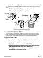
1
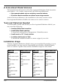
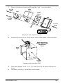
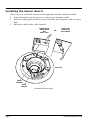
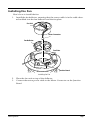
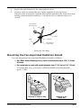
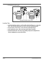
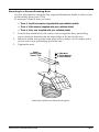
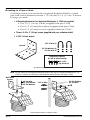
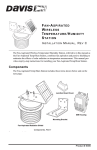
F A N -A S P I R A T E D
RADIATION SHIELD
INSTALLATION MANUAL
(For all models with Mfg. Code
beginning with B or higher)
The Fan-Aspirated Radiation Shield uses fan aspiration and passive shielding
to minimize the effects of solar radiation and to provide accurate temperature
readings. This instruction manual takes you step-by-step through the process
of installing and mounting your Fan-Aspirated Radiation Shield.
Note: Installation varies according to the shield type, so please take note of your product number before
you begin to install. You can find the model number on the label on the underside of the Fan Plate.
Components
The Fan-Aspirated Radiation Shield includes these items:
Mounting Bracket
with Solar Panel
Mounting Bracket
AC MODELS
7750, 7751, 7752
ONLY
SOLAR MODELS
7755, 7756, 7757
ONLY
3 Volt
Power Adapter
Fan-Aspirated
Radiation Shield
Standard
Sensor Cable,
40 feet (12 meters)
MODELS 7751, 7756
ONLY
Industrial
Sensor Cable,
16 feet (4.9 meters)
MODELS 7752, 7757
ONLY
#4 x 1/2" Screw
#4 Flat Washer
Cable Clamp
Junction Board Cover
AC MODELS
7750, 7751, 7752
ONLY
#8 Hex Nuts (3)
#8 Lock Washers (3)
#8 Flat Washers (3)
SOLAR MODELS 7755, 7756, 7757 ONLY
#4 Self-Threading Screws (4)
Battery Covers (2)
1.2 Volt Nicad Batteries (2)
O-Rings (2)
Product # 7750, 7751, 7752, 7755, 7756 & 7757
A Note About Model Versions
This manual is for all versions of the Fan-Aspirated Radiation Shield manufactured after 9/1/01. Earlier versions have the following differences:
✦ Solar-powered modules only use one battery versus two batteries
✦ All Junction Board-connections are soldered versus using connectors
Aside from those differences, the installation of the early versions of the
Fan-Aspirated Radiation Shield is the same as for current versions.
Tools and Materials Needed
To disassemble, install, and mount your Fan-Aspirated Radiation Shield, you
may need the following:
✦ A medium Phillips-Head screwdriver.
✦ A small Phillips-Head screwdriver.
To install an existing Davis Temperature/Humidity sensor.
✦ A small wrench or 3/8” (9 mm) nutdriver.
✦ A radiation shield bracket (#7994).
To mount the radiation shield on a mast or pipe if you wish.
Installation Steps
The Fan-Aspirated Radiation Shield comes pre-assembled. Depending on your
model number, you may need to disassemble your shield to install a battery
and/or a sensor or probe. Here are the installation steps for each shield.
Page 2
MODEL 7750
MODELS 7751 & 7752
MODEL 7755
MODELS 7756 & 7757
1. Disassemble the shield
Page 3
1. Disassemble the shield
Page 3
1. Disassemble the shield
Page 3
1. Disassemble the shield
Page 3
2. Install a sensor or probe
Page 4
2. Power the fan
Page 8
2. Install a sensor or probe
Page 4
2. Power the fan
Page 8
3. Install the sensor board
Page 6
3. Reassemble the shield
Page 12
3. Install the sensor board
Page 6
3. Reassemble the shield
Page 12
4. Power the fan
Page 8
4. Mount the shield
Page 15
4. Power the fan
Page 8
4. Mount the shield
Page 13
5. Route the cables
Page 10
5. Route the cables
Page 10
6. Reassemble the shield
Page 12
6. Reassemble the shield
Page 12
7. Mount the shield
Page 15
7. Mount the shield
Page 15
Fan-Aspirated Radiation Shield
Disassembling the Radiation Shield
Use a medium Phillips-Head screwdriver to disassemble as described below:
1.
2.
3.
4.
5.
Unscrew the three screws at the top of the unit and remove the mounting
bracket.
Remove the two plates and put aside.
Gently remove the fan and the deflector, taking care not to stress the wires
soldered to the terminal board.
Slide out the sensor board.
You are now ready to install a sensor or probe. (See page 5.)
2" Screws (3)
Mounting
Bracket
Lock Washers
Flat Washers
AC MODELS
Mounting Bracket
with Solar Panel
SOLAR MODELS
Closed Plate
(no hole in center)
Solar Power Cable
SOLAR MODELS
Open Plate
(hole in center)
Fan Unit
Fan Deflector
Motor
Connector
Sensor Board
with Temp Probe
Temp/Humidity Sensor
FACTORY INSTALLED
N MODELS 7751, 7752,
7756, AND 7757;
DO NOT REMOVE)
Fan Plate
Battery Compartment
Power Cable
AC MODELS
Core Unit
Baffles
Air Inlet (underneath)
Disassembling the Shield
Disassembling the Radiation Shield
Page 3
Installing a Sensor or Probe
For models without a pre-installed sensor, continue to the section “To install a
sensor or probe on the sensor board.” (See below).
If you want to install your own Davis Temperature/Humidity sensor (#7859 or
#7860), you must remove your old sensor housing and attach a new and
smaller sensor board cover. Please continue to the section “To attach a new
sensor board cover.” (See below.)
To install a sensor or probe on the sensor board:
1.
Attach the sensor or probe to the board using the cable ties.
Davis
Temp Probe
Sensor
Board
Vaisala
Temp Probe
Cable Ties
(2 places)
Cable Ties
(2 places)
Sensor
Board
Installing a Sensor or Probe on the Sensor Board
2.
You are now ready to install the sensor board. (See page 6.)
To attach a new sensor board cover:
If you have an existing Temperature/Humidity sensor model # 7859 or # 7860,
you need to attach a new sensor cover as follows:
1.
2.
Remove the shell and main cover by removing the screw at the front of the
board beside the cable exit point.
Remove the warranty label on the back of the cover and undo the screw.
Note: Removing this warranty label to attach a new sensor board does not void your warranty in this
instance. To avoid damaging sensitive components on the PC board, hold the board by the edges.
Page 4
Fan-Aspirated Radiation Shield
3.
Remove the sensor board and discard the “old” cover and shell.
#4 x 3/8"
Screw
Main
Cover
Shell
Sensor
Board
Base
#4 x 3/8"
Screw
#4 x 3/8"
Screw
Removing the “Old” Temp/Hum Housing
4.
Fit the new sensor cover on the front of the sensor board as shown below.
Board removed from
Davis #7859 or #7860
Temp/Humidity
Sensor
Sensor
Cover
#4 x 3/8"
Screw
Attaching a New Sensor Board Cover
5.
6.
Insert and tighten the #4 x 3/8” (9.5 mm) screw in the back of the sensor
board.
You are now ready to install the sensor board.
Installing a Sensor or Probe
Page 5
Installing the Sensor Board
Here’s how to install the sensor board supplied with the radiation shield:
1.
2.
3.
Insert the board into the grooves in the sensor chamber walls.
Push the cable gently into the sensor chamber, allowing the cable to loop a
little.
Route the cable to the cable channel.
Temp/Humidity
Sensor Board
with
Sensor Cover
OR
Temp Probe
mounted on
Sensor Board
Core Unit
Sensor
Chamber
Cable
Channel
Installing the Sensor Board
Page 6
Fan-Aspirated Radiation Shield
Installing the Fan
Here’s how to install the fan:
1.
Install the fan deflector, ensuring that the sensor cable is in the cable channel molded into the fan deflector and the fan plate.
Fan Unit
Motor Connector
Fan Deflector
Fan Plate
Junction Board
Installing the Fan
2.
3.
Place the fan unit on top of the deflector.
Connect the motor power cable to the Motor Connector on the Junction
Board.
Installing the Fan
Page 7
Powering the Fan
AC-powered models are powered by an AC-power adapter. Solar-powered
models have a solar power panel and use batteries for overnight power. Refer
to the Junction Board Connections illustration when powering the fan.
Solar Power Connector
(Solar-Powered Models Only)
For Future
Motor Connector Tachometer
MOTOR
+VSOL
+5V
TACH
AC Power Adapter Connector
(AC-Powered Models Only)
Junction Board Connections
AC-Powered Radiation Shield
1.
2.
3.
4.
5.
6.
7.
Locate the Junction Board on the fan plate (See page 7).
Connect the AC-power adapter to the +5V connector on the Junction Board.
Plug the AC-power adapter into an AC outlet.
Check to see that the fan is blowing air up and away from the sensor.
Unplug the AC power adapter from the AC outlet until you have finished
mounting the radiation shield.
Secure the AC power cable to the fan plate with the supplied cable clamp.
You are now ready to route the cables.
Junction
Board
AC Power-Adapter Connections
Page 8
Fan-Aspirated Radiation Shield
Solar Powered Radiation Shield
The solar-powered fan will begin operating as soon as you install the batteries.
To prevent discharging the batteries, only install the batteries immediately
before you mount the radiation shield.
1.
On the Radiation Shield fan plate, insert the O-ring in the groove around
the edge of each battery compartment.
#4 Screws
Battery Cover
1.2 Volt Nicad
Battery
O-Ring
Battery
Compartment
Installing the Batteries
(Solar-Powered Models Only)
2.
3.
4.
5.
Insert a NiCad battery in each compartment, matching the plus (+) sign on
the battery with the plus (+) sign in the battery compartment.
Verify that the fan is blowing air up and away from the sensor.
Attach the battery covers to the battery compartments using two #4 x 3/8”
(9.5 mm) screws each.
You are now ready to route the cables.
Installing the Fan
Page 9
Routing the Sensor and Power Cables
To route the cables do the following:
1.
2.
3.
4.
5.
Loosen the cable clamp screws on the top of the unit core, remove the cable
clamps.
Route the sensor cable and AC or solar power cable through the clamp.
Secure the clamp to the unit using the screw provided.
Connect the sensor cable to the appropriate connector on the junction
box/sensor interface. Consult your station installation manual for more
information.
For AC-powered models, route the power-adpater cable to an AC outlet
Use Cable Clamp to
Attach Cables
#4 x 1/2" Screw
Fan Plate
#4 Flat Washer
Cable Clamp
Battery
Compartments
(not used in
AC Models)
Fan Motor
Sensor Cable
Power Adapter
Cable
Junction
Board
AC Cable Routing
Page 10
Fan-Aspirated Radiation Shield
Fan Plate
#4 x 1/2" Screw
#4 Flat Washer
ter
Bat
t
Bat
ery
Cable Clamp
y
Motor
Sensor Cable
Battery
Wires
Solar Panel
Cable
Junction
Board
Solar Cable Routing
Note: You may want to test the sensor or probe before you mount the radiation shield. Please consult your
sensor, or probe installation manual to find out how to conduct the test.
To test the pre-installed Davis sensor:
1.
2.
3.
4.
Attach the sensor cable to the appropriate connector on the junction
box/sensor interface module (SIM).
Consult the weather station manual or installation manual for more information.
Press the appropriate key on your console as necessary to make sure you
are getting an outside air temperature reading on the console.
If you are using a Temp/Hum sensor, press the appropriate key on your
console as necessary to make sure you are getting an outside humidity
reading on your weather station console.
Once you complete this test, you are ready to reassemble the radiation
shield.
Routing the Sensor and Power Cables
Page 11
Reassembling the Radiation Shield
To reassemble the radiation shield, do the following:
1.
2.
3.
4.
Make sure the sensor cable runs through the provided cable channels and
that the fan unit is seated on the fan plate.
Slide the two sections partially together, leaving enough clearance so that
you have access to the Junction Board.
Check the Junction Board cable connections for the motor and for either the
solar power cable or the AC-power adapter cable.
Install the Junction Board Cover as shown below. The Junction Board Cover
presses easily into place when you are installing it. To remove the cover,
press gently in on both sides to release the latches holding it in place.
Press in on Sides
near latches
to Remove Cover
Junction Board Cover
Junction Board
Junction Board Cover Installation
Page 12
Fan-Aspirated Radiation Shield
5.
Place the open shield plates on top of the three threaded spacers as shown
below, making sure to line up the screw holes. Add the closed plate.
Use the plastic ridges on the underside of the plates as a guide.
2" Screws (3)
Mounting
Bracket
Lock Washers
Flat Washers
AC MODELS
Mounting Bracket
with Solar Panel
SOLAR MODELS
Closed Plate
(no hole in center)
Solar Power Cable
SOLAR MODELS
Open Plate
(hole in center)
Sensor Cable
Fan Plate
Power Cable
AC MODELS
Passive Shielding
Reassembling the Fan-Aspirated Radiation Shield
6.
7.
Secure the two shield plates to the radiation shield mounting bracket using
the three 2” screws and washers.
Tighten until the radiation shield attaches firmly to the mounting bracket.
You are now ready to mount the shield. (See page 14.)
Note: If you want to extend the length of the power cable, you will need to connect the cables using splice
connectors before mounting the shield. (See page 14.)
Reassembling the Radiation Shield
Page 13
Extending the AC Power Cable
The AC-power adapter has a 12’ (4 m) power cable. If you need a longer cable,
you can extend the power cable of the radiation shield using 2-conductor
speaker cable or zip cord with polarizing identification. That is, a zip cord with
one of the wires marked so you can identify the positive (+) and negative (-)
wires. If you plan on using the splice connectors supplied with the radiation
shield, we recommend a wire size of 19-24 AWG (0.9 -0.5 mm) with a maximum insulation of.082 in (2.08 cm). Connect the additional power cable using
splice connectors as follows:
1.
2.
Cut the cable ends square.
Separate the wires about 1” on both cables. Do not strip the insulation.
3.
Take the striped (or otherwise marked) wire from the supplied cable and
place it into one of the holes at the end of a splice connector.
Make sure you push the wire all the way into the connector. You can check
this by looking through the clear side of the splice connector.
Take the striped (or similarly marked) wire from the additional cable and
place it into the other hole at the end of the splice connector.
Again, make sure you push the wire all the way into the connector.
Separating the Wires
4.
Using Splice Connector
5.
Page 14
Use pliers to squeeze the green cap into place, securing the wires.
Fan-Aspirated Radiation Shield
6.
7.
Repeat this procedure for the other pair of wires.
Using a cable tie, secure the two cables together as shown below.
This provides a measure of strain relief which prevents the wires from separating under normal conditions. Cut off the excess cable tie when it is
secure.
Paired Wires
with Connectors
Cable
Cable Tie
Cable
Fold Cable for
Strain Relief
Securing the Two Cables
Mounting the Fan-Aspirated Radiation Shield
You can mount the Fan-Aspirated Radiation Shield as follows:
✦ On a Davis Sensor Mounting Arm or other horizontal plate up to 0.26” (6.6 mm)
thickness.
✦ On a metal pipe or mast with outside diameter from 1” (2.5 cm) to 1 1/4” (3.1 cm).
To mount this way, you need a radiation shield mounting bracket
(part # 7994).
Mounting on a Pipe or Mast
Mounting the Fan-Aspirated Radiation Shield
Mounting on the
Sensor Arm
Page 15
✦ On the side of a wall or post
Mounting on the Side of a Post or Wall
Location Tips
✦ Install the shield over plants or soil if possible. Avoid installing over or near sprin-
klers. The shield does not protect the sensor from water spraying upwards.
✦ Place the sensor 5 feet (1.5 m) or more from man-made heat sources.
✦ Avoid running the sensor cable across large metal objects if possible.
✦ Avoid placing the motor near any curing caulking compounds as deposits from
silicone compounds can cause motor failure.
Page 16
Fan-Aspirated Radiation Shield
Mounting to a Sensor Mounting Arm:
Use this procedure to attach the Fan-Aspirated Radiation Shield to a Davis Sensor Mounting Arm (part #7702).
To mount to a Sensor Arm you need:
✦ Three # 8 split lock washers (supplied with your radiation shield)
✦ Three # 8 flat washers (supplied with your radiation shield)
✦ Three # 8 hex nuts (supplied with your radiation shield)
1.
2.
3.
Position the shield below the Sensor Arm to align the three protruding
screws from the bracket with the three holes at the end of the arm.
Raise the shield into position and place a flat washer, a lock washer, and a
nut on each screw protruding above the arm.
Tighten the nuts.
Sensor
Mounting Arm
(Davis #7702)
#8 Hex Nuts
#8 Lock Washers
#8 Flat Washers
Attaching the Shield to the Sensor Mounting Arm
Mounting the Fan-Aspirated Radiation Shield
Page 17
Mounting to a Pipe or Mast
Use this procedure to mount the Fan-Aspirated Radiation Shield to a metal
pipe with outside diameter between 1” (2.5 cm) and 1 1/4” (3.1 cm). To mount
to a pipe you need:
✦ A Mounting Bracket for Fan Aspirated Shield (part # 7994-not supplied)
✦ Two 1 1/2” (3.8 cm) U-bolts (supplied with part # 7994)
✦ Four 1/4” (6.3 mm) flat washers (supplied with part # 7994)
✦ Four 1/4” (6.3 mm) hex nuts (supplied with part # 7994)
✦ Three # 8-32 x 2” (5.1 cm) screws (supplied with your radiation shield)
✦ A 7/16” (1.1 cm) wrench
1-1/2" U-Bolts (2)
Bracket
1/4" Flat Washers (4)
1/4" Hex-Nuts (4)
Supplied by customer
for wall or post mounting:
1/4" x 1-1/2"
Lag Screws (4)
Pipe Mounting Requirements
Note: You can mount the Fan-Aspirated Radiation Shield on any pipe to a maximum diameter of 2 1/2”
(6.35cm). However, you will need to drill additional holes and obtain the larger U-bolts.
Wall Mount
Bracket
#8 Hex Nuts
#8 Lock Washers
#8 Flat Washers
1-1/2" U-Bolts
1/4" Flat Washers
1/4" Hex Nuts
Mounting the shield to a Pipe or Mast
Page 18
Fan-Aspirated Radiation Shield
Mounting to the Side of a Post or Wall
To mount the Fan-Aspirated Radiation Shield on the side of a post or wall you
need:
✦ Four 1/4” (6.8mm) x 1 1/2” (3.8cm) lag screws (not supplied)
✦ A Mounting Bracket (part # 7994 - not supplied)
1/4" x 1-1/2"
Lag Screws
#8 Hex Nuts
#8 Lock Washers
#8 Flat Washers
OR
Wall Mount
Bracket
Mounting the Shield to the Side of a Post or Wall
Connecting the Sensor Cable
Once you mount the radiation shield, you can then connect the sensor cable
with the appropriate connector on the junction box/sensor interface module
(SIM). Consult your weather station owner’s manual for further details.
Securing the Sensor Cable
To prevent fraying or cutting of the cable or wires where they are exposed to
weather, you must secure them so they do not lash about in the wind. To secure
the cable and wires you need to:
✦ Use cable clips or weather resistant cable ties to secure the cable.
✦ Place clips or ties approximately every 3 to 5 feet (1 to 1.5 m).
✦ Avoid using metal staples or a staple gun to secure cables or wires since metal
staples installed with a staple gun can cut the cable and wires.
✦ Avoid tugging on the sensor cable when you run it. Leaving the connection taut
may cause strain and the cable may pull free.
Connecting the Sensor Cable
Page 19
Calibrating the Dew Point and Relative Humidity
If you want to install the Fan-Aspirated Radiation Shield as part of a Weather
Monitor II station, you need to calibrate the dew point and relative humidity.
Please refer to your weather station owner’s manual for calibration
instructions.
Maintenance Instructions
✦
Keep the surfaces clean as the Fan-Aspirated Radiation Shield is less effective when the surfaces are dirty. Remove dust from the solar panel and the
screen with a damp cloth.
✦
Remove any debris that obstructs air flow between the radiation shield
parts e.g., leaves, twigs, webs, and nests.
✦
Avoid spraying insecticide of any kind into the radiation shield as this may
damage the sensors and the shield.
✦
Once a year:
✦ Replace the fan/motor assembly (Part # 7758 (standard motor) or #
7759 (low current motor))
✦ Replace the batteries (solar-powered models only)
✦ Remove any debris lodged inside the unit
Replacing Fan Batteries
1.
2.
3.
4.
5.
Retrieve your Fan-Aspirated Radiation Shield and place on a stable work
surface.
Disassemble the Radiation Shield (See page 3).
Replace the old batteries (See page 9).
Assemble the Radiation Shield (See page 12).
Mount the Fan-Aspirated Radiation Shield in the desired location.
Replacing The Fan/Motor Assembly
1.
2.
3.
4.
5.
6.
Page 20
Retrieve your Fan-Aspirated Radiation Shield and place on a stable work
surface.
Disassemble the Radiation Shield (See page 3).
Unplug the old motor and remove from it from the Radiation Shield (See
page 7).
Install the new motor/fan assembly and plug it into the Junction Board
(See page 7).
Assemble the Radiation Shield (See page 12).
Mount the Fan-Aspirated Radiation Shield in the desired location.
Fan-Aspirated Radiation Shield
Troubleshooting
If you are experiencing problems with your Fan-Aspirated Radiation Shield,
first be sure to check all cable connections. If you are unable to solve the problem, please call Davis Technical Support. We’ll be glad to help. Most questions
can be answered while you’re on the phone. You can also email us for support,
or visit our website. Sorry, we are unable to accept collect calls.
Note: Please do not return items to the factory for repair without prior authorization.
Contacting Davis Instruments
(510) 732-7814 for Technical Support, Monday – Friday, 7:00 a.m. – 5:30 p.m.
Pacific Time.
(510) 670-0589 Fax to Customer Service or Tech Support.
[email protected] E-mail to Technical Support.
www.davisnet.com Copies of User Manuals are available on the “Support”
page. Watch for FAQs and other updates. Subscribe to the e-newsletter.
Diagram of Operation
The diagram below shows how the Fan-Aspirated Radiation Shield draws cool
outside air up through the sensor chamber and through the walls surrounding
the sensor chamber.
Air Flow in Fan-Aspirated Radiation Shield
Troubleshooting
Page 21
Template for Mounting Holes
3.24"
(82.3 mm)
1.62"
(41.1mm)
B
B
A
4.15"
(105.5 mm)
1.26"
(32 mm)
A
A
B
2.83"
(71.9 mm)
1.88"
(48 mm)
5.66"
(143.8 mm)
[Either set of 3 holes (A or B) may be used]
Page 22
Fan-Aspirated Radiation Shield
Troubleshooting
Page 23
Notes
Product Number: 7750, 7751, 7752, 7755, 7756 & 7757
Davis Instruments Part Number: 7395.084
Fan-Aspirated Radiation Shield
Rev. B Manual (9/17/01)
© Davis Instruments Corp. 2001. All rights reserved.
This product is protected in the United States by Patent Number 6,247,360.
3465 Diablo Avenue, Hayward, CA 94545-2778
510-732-9229 • Fax: 510-732-9188
E-mail: [email protected] • www.davisnet.com