1
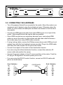
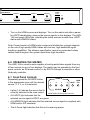
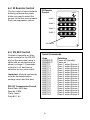
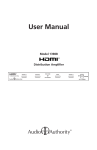
User Manual
Model HMX-144
HDMI Matrix Router
Table Of Contents
1.0
Introduction
. . . . . . . . . . . . . . . . . . . . . . . . . . . . . . 3
2.0
Checking Package Contents . . . . . . . . . . . . . . . . . . . . . . 3
3.0
Getting the Best Results . . . . . . . . . . . . . . . . . . . . . . . . 4
4.0
Planning a Matrix System . . . . . . . . . . . . . . . . . . . . . . . 5
5.0
Connecting The Hardware . . . . . . . . . . . . . . . . . . . . . . . 6
6.0
Operating the Matrix . . . . . . . . . . . . . . . . . . . . . . . . . . 7
7.0
Troubleshooting . . . . . . . . . . . . . . . . . . . . . . . . . . . . 9
8.0
Specifications . . . . . . . . . . . . . . . . . . . . . . . . . . . . .
10
9.0
Limited Warranty . . . . . . . . . . . . . . . . . . . . . . . . . . .
11
10.0
Regulatory Compliance
. . . . . . . . . . . . . . . . . . . . . . .
12
11.0
Contact Information . . . . . . . . . . . . . . . . . . . . . . . . .
12
Liability Statement
Every effort has been made to ensure that this product is free of defects. Audio Authority cannot be held
liable for the use of this hardware or any direct or indirect consequential damages arising from its use.
It is the responsibility of the user of the hardware to check that it is suitable for his/her requirements and
that it is installed correctly. All rights reserved. No parts of this manual may be reproduced or transmitted
by any form or means electronic or mechanical, including photocopying, recording or by any information
storage or retrieval system without the written consent of the publisher.
Audio Authority reserves the right to revise any of its hardware and software following its policy to modify
and/or improve its products where necessary or desirable. This statement does not affect the legal rights
of the user in any way.
Audio Authority and the Double-A Symbol are registered trademarks of Audio Authority Corp. Copyright
February, 2009, all rights reserved. All third party trademarks and copyrights are recognized.
HDMI, the HDMI logo and High-Definition Multimedia Interface are trademarks or registered trademarks
of HDMI Licensing LLC. HDCP (High-bandwidth Digital Content Protection) is licensed by Digital Content
Protection, LLC. Dolby is a trademark of Dolby Laboratories, Incorporated.
2
1.0 INTRODUCTION
Thank you for purchasing this Model HMX-144 HDMI Matrix Router from Audio
Authority. It is designed to route digital audio and video signals from four different
HDMI sources to four HDMI displays without signal degradation or loss of
encryption. The HMX-144 is HDCP v1.1 compliant, and HDMI v1.3 compliant,
supporting deep color video, Dolby TrueHD, and DTS-HD Master Audio.
Audio Authority also offers an extensive line of audio and video switchers,
converters, extenders and distribution amps available for purchase online at
www.audioauthority.com.
1.1 FEATURES
• Delivers four HDMI source signals to any or all of four compatible displays
• Supports deep color: 10 bits per TMDS channel (30 bit, sum of all channels)
• Supports 480i, 480p, 720p, 1080i, 1080p and multiple PC resolutions
•
Supports Dolby Digital Plus, Dolby® Digital TrueHD, DTS-HD: Master Audio,
and LPCM
• HDMI version 1.3 compliant, HDCP version 1.1 compliant
• IR remote control, RS-232 control, or front panel control
• Accepts locking HDMI cables
• IR extender included
2.0 CHECKING PACKAGE CONTENTS
Before attempting to use this matrix router, please check the packaging and
make certain the following items are contained in the shipping carton:
• HDMI matrix router
• IR remote control and IR extender
• 5V DC power adapter
• Rack mount hardware
• Jack screws (for locking HDMI ports)
• User manual
Note: please keep the original packing material in case the matrix ever needs
to be returned. If you find any items are missing, contact Audio Authority
immediately. Have the model number and invoice available for reference when
you call.
3
ZONE 1
POWER
1
2
3
4
HDCP
HDMI
DVI
Version 1.3
SOURCE
Model HMX-144 4x4 Video/Audio Matrix
3.0 GETTING THE BEST RESULTS
Many factors influence
the quality and reliability of HDMI signal distribution
RS-232
OUTPUTS
installations. The following are the main factors to consider,HDMI
andZONE
basic
ZONE 4
ZONE 3
ZONE 2
ZONE 1
precautions that will ensure the best possible performance.
EDID
• Resolution
tracking. Refer to 4.0 “Planning a Matrix System” Set up the
sources
to
output
the best resolution that all TVs can accept.
INT / AUTO
• Source resolution and video/sound quality. Sources, such as satellite
receivers or cable boxes may output at low resolutions or deliver extremely
compressed video material, yielding poor results. Consider the sources when
planning and troubleshooting your system.
• Output display devices. The quality of the output signal depends largely
upon the type and quality of the HDMI display devices used.
• Connection cables. HDMI cable design and quality are extremely important
in long cable runs where capacitance can severely degrade performance. Use
premium cables; low quality cables are susceptible to interference. Always use
locking cables or good strain relief methods to prevent cables from becoming
loose over time.
• Distance between the sources and the displays. Using premium quality
cables the sources may be located up to 20m from the matrix, and the matrix
may be up to 15m from each display device. Longer distances are possible
using advanced HDMI extenders with DDC correction.
• Interference. Nearby electrical devices can have an adverse effect on
signal quality. For example, older computer monitors often emit very high
electromagnetic fields that can interfere with the performance of adjacent
video equipment.
4
HDMI SO
SOURC
ZONE 2
1
2
3
4
HDCP
HDMI
DVI
ZONE 3
1
SOURCE
2
3
4
HDCP
HDMI
DVI
SOURCE
ZONE 4
1
2
3
4
HDCP
HDMI
DVI
SOURCE
4.0 PLANNING A MATRIX SYSTEM
• Each display should be individually tested by connecting it directly to each
POWER
5V DC
source
to3 ensure basicSOURCE
compatibility
before
them to a matrix. After
SOURCE 1 connecting
SOURCE
2
IR
testing the sources with the displays, temporarily connect
all of the sources
and displays to the matrix using short HDMI cables to verify compatibility and
function.
OURCE INPUTS
• Since all of the displays connected to a particular source will be receiving the
same video signal resolution and format (e.g. 1080p@60Hz) produced by
the source, make sure the source is set up to output the highest resolution
that all of the displays can accept. For instance, if one display can accept
a maximum input resolution of 720p, all of the sources are limited to 720p
output, and all displays will receive a maximum resolution of 720p. This
consideration is particularly important if the TVs have a wide range of
resolution capabilities because the highest resolution sets may not be allowed
to perform to their best advantage.
• HDMI cable lengths should be kept as short as possible. Use high quality
HDMI extenders (such as our Model 1391A) where cable lengths must exceed
15m. Use of high resolutions, refresh rate, or deep color may limit maximum
cable run length.
Higher
Resolution
Refresh Rate
Bit Depth
CE 4
Lower
Shorter Distance
Longer Distance
To the extent that high resolutions, refresh rate, or deep color are used, cable run length is
diminished. Use high quality HDMI cable extenders for long distance, high bandwidth applications.
5
RS-232
ZONE 4
HDMI ZONE OUTPUTS
ZONE 3
ZONE 2
ZONE 1
EDID
INT / AUTO
5.0 CONNECTING THE HARDWARE
• Turn off equipment that will be connected to the matrix. Mount the matrix in an
equipment rack if desired, using the included rack ears. Otherwise, place the
matrix on a flat surface with adequate ventilation and access to the front and
rear panels.
• Connect an HDMI approved cable from each HDMI source to an input of the
matrix. Cable lengths should be kept as short as possible.
• Since HDMI connectors can sometimes become loose, use locking HDMI
cables or mount the matrix to a flat surface and add strain relief tie-downs a
few inches away from every HDMI cable connector.
• If using locking cables, remove the Phillips screws above each HDMI port and
replace them with the hex-head jack screws provided. Plug in the HDMI cable
and insert the cable screws into the jack screw heads.
• Connect the outputs of the matrix to their destination devices.
• If you are using the infrared extension function, connect the extension IR
sensor cable and position the sensor.
• Connect the power adapter to the AC source and then to the matrix. Twist the
DC plug to 90 degrees in the matrix power port to lock.
• If you are using the RS-232 control function, connect an RS-232 cable with
pinout as shown below.
Pin # Definition
NC
1
Tx
2
Rx
3
NC
4
GND
5
NC
6
NC
7
NC
8
NC
9
MATRIX
END
CONTROLLER
END
SERIAL CONTROL CABLE
6
Pin # Definition
1
NC
2
Rx
3
Tx
4
NC
5
GND
6
NC
7
NC
8
NC
9
NC
HDMI SO
SOURC
OURCE INPUTS
CE 4
ER
SOURCE 3
POWER
5V DC
SOURCE 1
SOURCE 2
IR
• Turn on the HDMI sources and displays. Turn on the matrix and after a pause
for HDCP handshaking, observe the source signals on the displays. The HMX144 front panel LEDs light, indicating the active sources in each zone, HDCP
status and HDMI/DVI status.
Note: Proper function of HDMI matrix routers and distribution systems depends
on the use of high quality HDMI cables with low loss, high bandwidth signal
handling capabilities. The distance specification cannot be guaranteed unless
cables used throughout the system meet these high standards.
6.0 OPERATING THE MATRIX
The HMX-144 is a matrix router capable of routing audio/video signals from any
of four sources to any of four displays. The matrix may be operated by the front
panel controls, an IR remote control, or by RS-232 through a computer or other
third party controller.
6.1 Front Panel Controls
ZONE 1
Repeatedly press the SOURCE button
HDMI
1 appropriate
2
3 zone4 until
HDCP
DVI
in the
the desired
source (1, 2, 3, or 4) is selected.
ZONE 2
1
SOURCE
• Lights (1-4)
indicate the source that is
currently selected to the zone output.
2
3
4
HDCP
HDMI
DVI
SOURCE
Model HMX-144 front panel controls
• A lit HDCP light indicates that the
selected source signal is HDCP encrypted.
• A lit HDMI/DVI light indicates that the selected source signal is compliant with
HDMI and/or DVI standards.
• The lit Power light indicates that the unit is receiving power.
7
HDMI ZONE OUTPUTS
HDMI SOURCE INPUTS
1
6.2 IR Remote Control
The four rows of source selector
buttons just below the power
button are used to select the
source on the four zone outputs.
Each row represents a zone.
IR Remote
Control
POWER
OUTPUT
ZONE 1
1 1
2
3
4
2
3
4
2
3
4
2
3
4
OUTPUT
ZONE 2
2 1
OUTPUT
ZONE 3
3 1
OUTPUT
ZONE 4
4 1
SOURCES
6.3 RS-232 Control
Connect a computer or other
serial controller to the RS-232
port on the rear panel using a
cable with pin connections as
shown on page 6. Commands
include on, off, and source
selection on any zone output.
Important: all serial commands
must be terminated with a
carriage return and line feed.
RS-232 Transmission Format
Baud Rate: 9600 bps
Data bit: 8 Bits
Parity: None
Stop Bit: 1 bit
Serial Commands
Code
POWER 00
POWER 01
PORT 11
PORT 12
PORT 13
PORT 14
PORT 21
PORT 22
PORT 23
PORT 24
PORT 31
PORT 32
PORT 33
PORT 34
PORT 41
PORT 42
PORT 43
PORT 44
8
Definition
Power off (standby)
Power on
Zone 1, select Source 1
Zone 1, select Source 2
Zone 1, select Source 3
Zone 1, select Source 4
Zone 2, select Source 1
Zone 2, select Source 2
Zone 2, select Source 3
Zone 2, select Source 4
Zone 3, select Source 1
Zone 3, select Source 2
Zone 3, select Source 3
Zone 3, select Source 4
Zone 4, select Source 1
Zone 4, select Source 2
Zone 4, select Source 3
Zone 4, select Source 4
7.0 TROUBLESHOOTING
• Make certain that the matrix is receiving power by looking at the power LED.
It should be illuminated and not flickering. Intermittent operation generally
means a problem with the DC power adapter or low AC voltage. Check the AC
outlet for proper voltage, then consider replacing the DC power adapter.
• If some lower resolution TVs do not display a picture, make sure the source is
producing a resolution low enough that all TVs can accept it. Try 1080i, 720p
and 480p. If possible, manually set your sources to the desired resolution.
In some cases, hot-plugging a high resolution display may actually reset the
source to a resolution that cannot be accepted by some other TVs.
• If displays seem to “lose signal” momentarily, this may be normal HDMI
switching behavior. All displays connected to a source must handshake again
when that source is selected to a new display. This pause is normal and
required when switching HDCP encrypted signals.
• If some inputs function correctly and others do not, interchange cables
between sources and see if the problem moves with the cables. If it moves,
a bad cable or cable connector is the probable reason for the trouble. If the
problem remains with one particular input, connect that source to a different
input using the same cable and see if the problem moves to the new input. If it
does, the problem is with the source. Connect the source directly to the lowest
resolution display and adjust its output settings and resolution until satisfactory
function is achieved.
• If 1080p resolution is desired, first make certain that the input cable is as short
as possible and none of the output cables are more than 15 meters long.
HDMI cable design and quality are extremely important in long cable runs
where capacitance can severely effect performance. One of our high quality
HDMI extenders should be used in extreme length/high bit depth applications.
• Remember that HDMI devices communicate with one another so the source
device and all destination devices must be fully HDMI compliant. In addition,
HDCP encryption requires processing dependent on the equipment you have
connected to both the source and destination devices.
If a problem still persists after trying the above suggestions, contact the Audio
Authority Technical Support department via email:
[email protected], or call 800-322-8346 or 859-233-4599.
9
8.0 SPECIFICATIONS
Video Inputs
Video Outputs
Audio Inputs
Audio Outputs
Compliance
Signal Processing
Jitter Processing
Color Processing
Data Rate
TMDS Clock Speed
Video Resolutions
Audio Processing
EDID
Maximum Cable Length
Control Methods
Mechanical
Limited Warranty
Environmental
Storage Humidity
Power Requirement
Regulatory Approvals
Accessories Included
Optional Accessories
HDMI video (or DVI w/cable adapters)
4x via HDMI Type A connectors*
HDMI Video (or DVI with cable adapters)
4x via HDMI Type A connectors*
HDMI embedded digital audio including Dolby® TrueHD
& DTS-HD: Master Audio, Dolby Digital Plus
HDMI embedded digital audio including Dolby® TrueHD
& DTS-HD: Master Audio, Dolby Digital Plus
HDMI v1.3, HDCP 1.1, DVI 1.0
Compensated, clock phase adjusted
Reconstituted signal; jitter free
30 bit (10 bits per TMDS color channel)
2.25Gbps (single link)
225MHz
480i through 1080p, VGA through UXGA
Dolby, DTS 32-192fs sample, LPCM 7.1/ch
Automatic or manual monitor discovery
Input: 20m (66 ft.) @ 1080p/8 bit
Output: 15m (49 ft.) @ 1080p/8 bit
Front panel, infrared remote, RS-232
Size: (H-W-D) 1.75”x 17.2”x 6.9” (44x438x175mm)
Weight: (Net) 6.8 lbs (3.1Kgs)
1 Year Parts and Labor
Operating temperature: +32º to +122º F (0º to +50º0 C)
Operating Humidity: 10% to 90%, Non-condensing
Storage temperature +14º to +140º F (-10º to +60º C)
10% to 90%, Non-condensing
External power supply 5V DC
Matrix unit: FCC, CE, RoHS
Power supplies: UL, CUL, CE, PSE, GS, RoHS
AC power adapter: USA type, locking connector
IR remote control
Rack mount kit
Jack screws for locking HDMI cables
IR extender
User manual
HDMI cables, extenders and distribution amplifiers
*Jack screws have been included to accommodate locking type HDMI connectors.
10
9.0 LIMITED WARRANTY
If this Audio Authority product fails due to defects in materials or workmanship
within one year from the date of the original sale to the end-user, Audio Authority
guarantees that we will replace the defective product at no cost. Freight charges
for the replacement unit will be paid by Audio Authority (Ground service only).
A copy of the invoice showing the item number and date of purchase (proofof-purchase) must be submitted with the defective unit to constitute a valid inwarranty claim.
Units that fail after the warranty period has expired may be returned to the factory
for repair at a nominal charge, if not damaged beyond the point of repair. All
freight charges for out-of-warranty returns for repair are the responsibility of the
customer. Units returned for repair must have a Return Authorization Number
assigned by the factory.
This is a limited warranty and is not applicable for products which, in our opinion,
have been damaged, altered, abused, misused, or improperly installed. Audio
Authority makes no other warranties either expressed or implied, including
limitation warranties as to merchantability or fitness for a particular purpose.
Additionally, there are no allowances or credits available for service work or
installation performed in the field by the end user.
9.1 Warranty Service Procedures
If you suspect a product defect, contact Audio Authority’s Technical Support
Department at 800-322-8346 or 859-233-4599 for assistance in verifying the
problem. If a defect or potential defect is suspected, a replacement unit will be
shipped immediately on a defect-exchange basis and a Return Authorization
Number will be issued for the return of the defective product. Replacement units
are sent out at the Manufacturer’s Suggested Retail Price which is debited to the
Customer’s Credit Card at the time of shipment. Once we receive the defective
unit back at the factory, it will be evaluated under the conditions of this warranty
and if found to be in-warranty, a full credit will be issued to the Customer’s
Credit Card. Return freight charges for the defective unit are the customer’s
responsibility. Please contact our Technical Service Department for complete
details concerning all in and out of warranty service matters.
We appreciate your confidence in our products and services and will always
strive to meet or exceed your needs.
11
10.0 REGULATORY COMPLIANCE
The HMX-144 matrix has been tested for compliance with appropriate FCC and
CE rules and regulations and is also RoHS compliant.
The included power supply has been tested for compliance with UL, CE and CSA
rules and regulations and is also RoHS compliant.
11.0 CONTACT INFORMATION
If you have questions or require assistance with this product in areas not covered
by this manual, please contact Audio Authority using the information below.
Audio Authority Technical Support
800-322-8346 M-F 8:30 AM to 5:00 PM, EST
International: 859-233-4599 Fax: 859-233-4510
Send email to: [email protected]
Audio Authority Corporation
2048 Mercer Road
Lexington, Kentucky 40511-1071
USA
2048 Mercer Road, Lexington, Kentucky 40511-1071
Phone: 859-233-4599 • Fax: 859-233-4510
Customer Toll-Free USA & Canada: 800-322-8346
Website: http://www.audioauthority.com
E-085
4/09