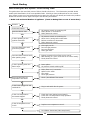
1
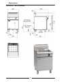
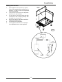
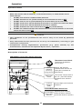
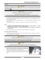
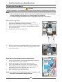
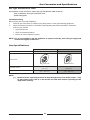
Installation and Operation Manual HPO Fast-Fri Gas Fryer FN8130GHPO FNL8130GHPO Date Purchased Serial Number Dealer Service Provider 228686-13 MANUFACTURED BY Moffat Limited Christchurch New Zealand INTERNATIONAL CONTACTS AUSTRALIA Moffat Pty Limited E.Mail: [email protected] Main Office: (tel): +61 (03) 9518 3888 (fax): +61 (03 9518 3833 Service: (tel): 1800 622 216 Spares: (tel): 1800 337 963 Customer Service: (tel): 1800 335 315 (fax): 1800 350 281 CANADA Serve Canada Web: E.Mail: Sales: Service: www.servecanada.com [email protected] (tel): 800 551 8795 (Toll Free) (tel): 800 263 1455 (Toll Free) NEW ZEALAND Moffat Limited Web: E.Mail: Main Office: www.moffat.co.nz [email protected] (tel): 0800 663328 UNITED KINGDOM Blue Seal Web: E.Mail: Sales: Spares: Service: www.blue-seal.co.uk [email protected] (tel): +44 121 327 5575 (fax): +44 121 327 9711 (tel): +44 121 322 6640 (fax): +44 121 327 9201 (tel): +44 121 322 6644 (fax): +44 121 327 6257 UNITED STATES Moffat Web: Sales: Service: www.moffat.com (tel): 800 551 8795 (Toll Free) (tel): +1 336 661 1556 (fax): +1 336 661 9546 (tel): 800 858 4477 (Toll Free) (tel): +1 366 661 1556 (fax): +1 336 661 1660 REST OF WORLD Moffat Limited Web: E.Mail: www.moffat.co.nz [email protected] The reproduction or copying of any part of this manual by any means whatsoever is strictly forbidden unless authorized previously in writing by the manufacturer. In line with policy to continually develop and improve its products, Moffat Ltd. reserves the right to change the specifications and design without prior notice. © Copyright Moffat Ltd. September 2012. Contents Waldorf GHPO Gas Fryer FN(L)8130GHPO 'FAST-FRI' GAS FRYER (Single Tank - 31 ltr) Introduction ............................................................................................. 2 Specifications ........................................................................................... 3 Model Numbers Covered in this Specification Gas Supply Requirements Electrical Supply Requirements Dimensions ................................................................................................ 4 Installation ................................................................................................ 5 Installation Requirements Unpacking Location Clearances Assembly Electrical Connection Fitting Rear Rollers Gas Connection Commissioning Operation ................................................................................................ 10 Operation Guide Description of Controls Filling the Tank Lighting Main Burners Setting Operating Temperature Turning ‘OFF’ the Fryer Cleaning and Maintenance ...................................................................... 13 General Draining and Daily Cleaning Weekly Cleaning Periodic Maintenance Fault Finding ........................................................................................... 16 Guide to Cooking Problems with Fryer Fault Finding the Gas System - Fault Finding Table Circuit Schematic .................................................................................... 19 Gas Conversion and Specifications ......................................................... 20 Conversion Procedure Gas Specifications Replacement Parts List ........................................................................... 22 Introduction We are confident that you will be delighted with your Waldorf HPO Fast-Fri Gas Fryer and it will become a most valued appliance in your commercial kitchen. To ensure you receive the utmost benefit from your new appliance, there are two important things you can do. Firstly Please read the instruction book carefully and follow the directions given. The time taken will be well spent. Secondly If you are unsure of any aspect of the installation, instructions or performance of your appliance, contact you WALDORF dealer promptly. In many cases, a phone call could answer your questions. Warning IMPROPER INSTALLATION, ADJUSTMENT, ALTERATION, SERVICE OR MAINTENANCE CAN CAUSE PROPERTY DAMAGE, INJURY OR DEATH. READ THE INSTALLATION, OPERATING AND MAINTENANCE INSTRUCTIONS THOROUGHLY BEFORE INSTALLING OR SERVICING THIS APPLIANCE. Warning INSTRUCTIONS TO BE FOLLOWED IN THE EVENT THE USER SMELLS GAS ARE TO BE POSTED IN A PROMINENT LOCATION. THIS INFORMATION SHALL BE OBTAINED BY CONSULTING THE LOCAL GAS SUPPLIER. Warning GREAT CARE MUST BE TAKEN BY THE OPERATOR TO USE THE EQUIPMENT SAFELY TO GUARD IT AGAINST RISK OF FIRE. THE APPLIANCE MUST NOT BE LEFT ON UNATTENDED. IT IS RECOMMENDED THAT A REGULAR INSPECTION IS MADE BY A COMPETENT SERVICE PERSON TO ENSURE CORRECT AND SAFE OPERATION OF YOUR APPLIANCE IS MAINTAINED. DO NOT STORE OR USE GASOLINE OR OTHER FLAMMABLE VAPOURS OR LIQUIDS IN THE VICINITY OF THIS OR ANY OTHER APPLIANCE. DO NOT SPRAY AEROSOLS IN THE VICINITY OF THIS APPLIANCE WHILE IT IS IN OPERATION. Caution This appliance is for professional use and is only to be used by qualified persons. Only authorised service persons are to carry out installation, servicing or gas conversion operations. Components having adjustments protected (e.g. paint sealed) manufacturer should not be adjusted by the user / operator. DO NOT operate the appliance without the legs supplied fitted. 2 by the Specifications Model Numbers Covered in this Specification FN[1]8130GHPO 'FAST FRI' GAS FRYER (Single Tank - 31 ltr). NOTE: [1] - Back Options; L - Standard Models. - Low Back Models. Gas Supply Requirements Input Rating (N.H.G.C.) Operating Pressure Burner Pressure Natural Gas LP Gas (Propane) 140 MJ/hr 140 MJ/hr (133,000 Btu/hr) (133,000 Btu/hr) 1.13 - 3.40 kPa 2.75 - 3.40 kPa (4.5” - 13.5” w.c.) (11” - 13.5” w.c.) 0.87 kPa (*) 2.55 kPa (*) (3.4” w.c.) (10.2” w.c.) Gas Connection NOTE: (*) ¾” BSP Male Measure burner operating pressure at Operating Pressure Test Point (Lower - Out) on gas control valve with both burners operating at the 'High Flame' setting. Refer to 'Gas Conversion and Specification' Section for further details. Electrical Supply Requirements FN8130GHPO - 220-240 V a.c, 50 Hz, 0.5A, 1P+N+E. 3 pin 10A cord set fitted. 3 Dimensions Dimensions: FN(L)8130GHPO 4 Installation Installation Requirements NOTE: It is most important that this appliance is installed correctly and that operation is correct before use. Installation shall comply with local gas, electrical and health and safety requirements. This appliance shall be installed with sufficient ventilation to prevent the occurrence of unacceptable concentrations of health harmful substances in the room, appliance is installed in. Waldorf 'FAST-FRI' HPO Fryers are designed to provide years of satisfactory service, and correct installation is essential to achieve the best performance, efficiency and trouble-free operation. This appliance must be installed in accordance with National installation codes and in addition, in accordance with relevant National / Local codes covering gas, electrical, fire and health and safety. Australia / New Zealand: - AS5601.1 - Gas Installations. Australia / New Zealand: - AS / NZS3000 - Wiring Rules. Installation must be carried out by authorised persons only. Failure to install equipment to relevant codes and manufacturers specifications shown in this section will void the warranty. Components having adjustments protected (e.g. paint sealed) by manufacturer are only to be adjusted by an authorised service agent. They are not to be adjusted by the installation person. Unpacking Remove all packaging and transit protection from appliance, including all protective plastic coating from door, outer panels and exterior stainless steel panels. Check equipment and parts for damage. Report any damage immediately to carrier and distributor. Report any deficiencies to distributor who supplied appliance. Check available gas supply is correct to as shown on rating plate located behind access door. Check the following parts have been supplied with the appliance:Baskets Basket Grids Lid Drain Stick Drain Extension FN8130GHPO 2 1 1 1 1 Location 1. 2. This appliance must be installed in a suitably ventilated room to prevent dangerous build up of combustion products. Installation must allow for a sufficient flow of fresh air for combustion air supply. Combustion air requirements:Combustion Air Requirements All Gas Types 3. 4. 5. 6. 24 m³/hr minimum. Never directly connect a ventilation system to the appliance flue outlet. A minimum of 610mm clearance must be maintained from flue outlet to any above surface. Position appliance in its approximate working position. All air for burner combustion is supplied from beneath the unit. Legs must always be fitted and no obstructions placed beneath or around base of fryer, as obstructions will cause incorrect operation and / or failure of the fryer. NOTE: Do not obstruct or block the appliance flue. system to the appliance flue outlet. 5 Never directly connect a ventilation Installation Clearances NOTE: Only non-combustible materials can be used in close proximity to this appliance. To allow easy operation, drainage and servicing of appliance, a minimum of 600mm clearance should be maintained at front of appliance. Any gas burning appliance requires adequate clearance and ventilation for optimum and trouble-free operation. The following minimum installation clearances are to be adhered to: Combustible Surface Non Combustible Surface Left / Right Hand Side 50mm 0mm Rear 50mm 0mm Assembly This model is delivered completely assembled. Ensure that the legs are securely attached. NOTE: This appliance is fitted with adjustable feet so that the appliance can be positioned securely and level. This should be carried out on completion of gas connection. Refer to 'Gas Connection Section'. This appliance can also be fitted with rear rollers to enable it to be easily moved for positioning and cleaning. If desired, these rollers are supplied in the packaging, with the appliance. See overleaf for fitting instructions. Electrical Connection NOTE: ALL ELECTRICAL CONNECTIONS MUST ONLY BE CARRIED OUT BY AN AUTHORISED PERSON. Each fryer should be connected to an adequately protected power supply and isolation switch mounted adjacent to, but not behind fryer. This switch must be clearly marked and readily accessible in case of fire. NOTE: This appliance must be grounded / earthed. 6 Installation Fitting Rear Rollers. 1. 2. 3. 4. 5. 6. Appliance Base Raise appliance from the floor by approx. 75mm using suitable lifting equipment (i.e. Palletiser / Forklift) to allow rear adjustable feet to be removed. Unscrew and remove both rear adjustable feet from rear leg housings. Fit rear roller to rear leg housing and align screw hole in side of rear leg housing with threaded hole in rear roller. Secure rear roller to leg support with bolt supplied and tighten bolt. Fit second roller and tighten. Lower appliance back to floor and adjust front adjustable feet to level appliance. Fig 1 Rear Leg Housing Roller Locating Bolt Adjustable Foot 7 Rear Roller Assy Installation Gas Connection NOTE: ALL GAS FITTING MUST ONLY BE CARRIED OUT BY AN AUTHORISED PERSON. - Flexible Hose Connection If a Gas Hose assembly is used to connect this appliance, hose and all fittings must have a minimum ¾” (Natural Gas) or ½” (LPG) inside bore diameter to ensure gas flow rate capacity required by this appliance is achieved. This must be verified by operating pressure testing at maximum gas supply demand condition. The Gas Hose assembly should also be classified for use in commercial kitchen conditions, appliance will be used in. Recommended Gas Hose Assembly Specification: - AS/NZS 1869 Class B or D compliant or equivalent, that meets the following requirements:- 1. Class Max Working Pressure at 23 ± 2ºC B 7.0 kPa D 2.6 MPa Working Temperature Range Resistance to Oil - 20ºC to + 125ºC Oil resistant lining and cover. It is essential that the gas supply is correct for appliance being installed and that adequate supply pressure and volume are available. Carry out the following checks before installation:a. Gas Type the appliance has been supplied for is shown on coloured stickers located above the gas connection point and next to the rating plate. Check that this is correct for gas supply the appliance is being installed for. Gas conversion procedure is shown in this manual. b. Supply Pressure required for this appliance is shown in ‘Specifications’ section of this manual. Check gas supply to ensure adequate supply pressure exists. c. Input Rate of this appliance is shown on Rating Plate fitted to inside of access door and in ‘Specifications’ section of this manual. Input rate should be checked against available gas supply line capacity. Particular note should be taken if appliance is being added to an existing installation. Fig 2 NOTE: It is important that adequately sized piping runs directly to connection joint on the appliance, with as few tees and elbows as possible to give maximum supply volume. 2. A suitable joining compound which resists the breakdown action of LPG must be used on every gas line connection, unless compression fittings are used. Connection to appliance is 3/4” BSP male. NOTE: A Manual Isolation Valve must be fitted to the individual appliance supply line. 3. 4. 5. Correctly locate the appliance into its final operating position, using a spirit level, adjust legs so that unit is level and at the correct height. Connect gas supply to appliance. Check all gas connections for leakage using soapy water or other gas detecting equipment. Warning DO NOT USE A NAKED FLAME 8 TO CHECK FOR GAS LEAKAGES. Installation 6. Check gas supply pressure is as shown in Specifications section, Gas Supply Requirements table. NOTE: Measure supply pressure at Upper Test Point (Supply Pressure) on gas control valve. Supply Pressure Test Point Pressure Adjusting Screw Caution Ensure the fryer tank(s) is / are filled with either water or oil prior to starting Main Burners otherwise damage may be caused to tank(s). 7. 8. 9. Operating Light Main Burners. Refer to ‘Operation’ section, ‘Lighting the Main Pressure Burners’. Fig 3 Test Point Verify that the supply pressure is still correct. Check Main Burner operating pressure (Adjust, using ‘Operating Pressure Adjusting Screw’ on gas control valve, see Fig 3), and as shown in ‘Gas Conversion and Specifications’ section, ‘Main Burner Operating Pressure Adjustment’. NOTE: Insufficient gas supply line capacity, indicated by supply pressure drop during maximum gas supply demand, is NOT ACCEPTABLE and may invalidate manufacturers warranty for this appliance. Commissioning Carry out the following commissioning checks before handing over the fryer for use, to ensure that the fryer operates correctly and operator(s) understand correct operating procedure. 1. Before leaving the new installation; a. Check the following functions in accordance with operating instructions shown in 'Operation' section of this manual. Light the Main Burners. Check the Thermostat Operation (refer to 'Operation' section of this manual). b. Thermostat operation check should be carried out by filling the fryer with oil / shortening to the oil 'FILL LEVEL' mark at rear of the tank and setting the thermostat to 180°C. Turn ON main burners as shown in 'Operation Instructions' in this manual. c. Once oil is up to temperature, check thermostat calibration. If a discrepancy is found, thermostat calibration should be referred to the supplier. d. Ensure each operator has been instructed in areas of correct lighting, operation, and shutdown procedures for this appliance. Initial Start-Up Before using the fryer; a. For first time use of the fryer, prior to using for cooking product, fill the fryer with oil and operate for about 1 hour at ‘Full Flame’ setting to remove any fumes or odours which may be present from the new appliance. b. Refer to the Operation Section of this manual for details on how to operate the fryer. 2. This manual must be kept by the owner for future reference and a record of Date of Purchase, Date of Installation and Serial Number of Unit recorded and kept with this manual. (These details can be found on Rating Plate attached to rear of access door. Refer to Figure 2). NOTE: If it is not possible to get appliance to operate correctly, shut off gas supply and contact the supplier of this unit. 9 Operation Operation Guide Warning GREAT CARE MUST BE TAKEN BY OPERATOR, TO USE THE FRYER SAFELY, TO GUARD AGAINST RISK OF INJURY AND FIRE. DO NOT LEAVE FRYER UN-ATTENDED DURING OPERATION. DO NOT REPLENISH THE OIL (FRYING MEDIUM) IN THE FRYER WHEN THE FRYER IS HOT. DO NOT OVER FILL THE OIL (FRYING MEDIUM) IN THE FRYER ABOVE THE TOP LEVEL MARK. DO NOT ALLOW THE OIL (FRYING MEDIUM) IN THE FRYER TO FALL BELOW THE LOWER LEVEL MARK. DO NOT ALLOW THE OIL (FRYING MEDIUM) IN THE FRYER TO OVERHEAT. DO NOT INTRODUCE WET FOOD OR WATER INTO THE HOT OIL (FRYING MEDIUM). DO NOT USE FLAMMIBLE SOLVENTS AND CLEANING AIDS ON OR IN CLOSE PROXIMITY TO THE FRYER WHILST THE FRYER IS STILL HOT. Caution This appliance is for professional use and is only to be used by qualified persons. Only authorised service persons are to carry out installation, servicing or gas conversion operations. Components having adjustments protected (e.g. paint sealed) manufacturer should not be adjusted by the user / operator. by the Description of Controls FN8130GHPO (Access Door Shown Removed) Thermostat Control Knob Temperature Graduations 95°C to 195°C. Heating ‘ON’ Indicator. (Indicates when burners are cycling On to maintain set (Green top) (Orange bottom) temperature). Heating Indicators Main Power Switch Turns power ‘ON’ and ‘OFF’ to the unit. (Red LED Indicator illuminates when switched ‘ON’). Lock Out Indicators (Red) Left and Right Lock Out Reset Indicators. Located Behind Main Access Door Left and Right Operating these switches Burner Reset resets the burner selected. (Press and release to operate). Switches Fig 4 10 Operation Filling the Tank Warning IS BELOW THE MINIMUM 'LO' INDICATED LEVEL DANGER OF FIRE EXISTS IF OIL LEVELWarning CORRECT LEVEL FOR FRYING MEDIUM WHEN AT FRYING TEMPERATURE. INDICATES CORRECT FRYING MEDIUM LEVEL WHEN COLD. Fig 5 NOTE: WALDORF 'FAST-FRI HPO' fryers can be used with both oil and shortening. 1. Before filling the tank, always check that the drain valve, located behind the access door, is closed. A locking slide is provided on the valve and this should always be locked in position during use. OIL - Carefully fill the fryer tank with oil to the lower ‘Fill Level’ mark shown at the rear of the tank. Set the thermostat to the required operating temperature, the oil will expand as heated and will reach the upper level mark when the oil is hot (180-190°C). GT60HPO fryer will hold 31 litres of oil. SHORTENING - Ideally shortening should be pre-melted prior to putting it into the tank. This is normally done in a suitable vessel on a boiling table burner. The liquefied shortening can then be poured into the tank until it reaches the 'FILL LEVEL' mark. GT60HPO fryer will hold 46.5 lbs shortening. Pre-Heating NOTE: When pre-melting shortening, only heat until the shortening is just liquefied. Do not bring shortening up to high temperature as handling of hot shortening is dangerous. If pre-melting of shortening is not possible, carefully cut the shortening in to small pieces and pack into the tank Light main burners and manually cycle burners On/Off until shortening has liquefied. Ideally main burners should be cycled On for 5 seconds and Off for 10 seconds. Repeat the cycle until all the shortening is melted. Following this procedure should allow shortening to liquefy gradually without scorching. Once shortening has liquefied, it can be brought up to fryer operating temperature. To speed up this process, break up the shortening and stir carefully during the melting process. Add more shortening until the tank is filled to the level marked on the tank side. Refer to Fig 5 above. NOTE: Running burners continuously will cause shortening in contact with the tank to overheat, resulting in premature oil breakdown. Never allow shortening to smoke while melting as this indicates that the temperature is too high. If shortening starts smoking, increase main burner 'Off' intervals. 11 Operation Lighting Main Burners 1. 2. 3. 4. 5. Turn ‘ON’ fryer main power switch, located in the centre of lower control panel. Main power switch will illuminate (Red) and green (Power On) neon on right hand side of upper control panel will illuminate. Check the 2 (Red) lock out indicator Led's on left hand side of control panel are not illuminated. If any of the lock out indicators are illuminated, press left or right hand burner reset switches on either side of the main power switch, to reset the control system for that side burner. Set thermostat knob to required frying temperature. The ‘Orange’ heating indictor on the RH Side of the top control panel will illuminate when burners are On and will go out when oil is at pre-set temperature. If left or right ‘Red ‘Lock Out’ indicators illuminate, press left or right burner reset switches on either side of the main power switch, to reset control system for that burner. Setting Operating Temperature 1. 2. 3. 4. 5. The temperature used for frying food is the most important aspect of fryer operation. Incorrect temperatures will result in poor product quality and will reduce life of oil / shortening. Temperature can be set from 95°C to 195°C, we do not recommend food be cooked above 190°C. Main burners will operate automatically to maintain this temperature. As a safety precaution all Waldorf 'Vee-Ray' fryers feature an Over-Heat control which will turn Off the fryer in the event that the oil reaches over 220°C, should there be a thermostat failure. If a fault occurs or the fryer is not functioning correctly, contact your local service agent. Turning ‘OFF’ the Fryer Caution Turning OFF thermostat does not turn OFF main power to fryer. Power should ALWAYS be turned OFF at main power switch located behind access door. 1. 2. 3. Turn 'OFF' the main power switch located on the fryer front control panel, the red indicator on the ‘ON’ - ‘OFF’ main power switch and the green neon on the right of the upper control panel will extinguish. Close the main access door. Check that the two ‘Red’ neon Lockout indicators located on the front control panel are extinguished. The thermostat control knob can be left at the normal operating temperature for future use. IMPORTANT: Should any abnormal operation like; - ignition problems, - abnormal burner flame, - burner control problems, - partial or full loss of burner flame in normal operation, If any of the above problems are noticed, the appliance requires IMMEDIATE service by a qualified service person and should not be used until a service is carried out. 12 Cleaning and Maintenance General Warning DO NOT USE FLAMMIBLE FRYER IS STILL HOT. SOLVENTS AND CLEANING AIDS ON OR IN CLOSE PROXIMITY TO FRYER WHILST Caution Always turn ‘Off’ gas supply before cleaning. This appliance is not water proof. Do not use water jet spray to clean interior or exterior of this appliance. To achieve the best results, cleaning must be regular and thorough and all controls and mechanical parts checked and adjusted periodically by a competent serviceman. If any small faults occur, have them attended to promptly. Don't wait until they cause a complete breakdown. It is recommended that the appliance is serviced every 6 months. Clean the fryer regularly. A clean fryer looks better, will last longer and will perform better. NOTE: DO NOT use abrasive detergents, sharp scrapers, strong solvents or caustic detergents as they could corrode or damage the fryer. Ensure that any detergent or cleaning material has been completely removed after each cleaning. To keep your fryer clean and operating at peak efficiency, follow the procedures below:Draining and Daily Cleaning 1. At end of each day or at the end of each shift, if frying schedule is heavy, frying medium should be drained and filtered into a receptacle. Warning DO NOT ATTEMPT TO MOVE FRYER WHILST FRYER IS FULL OF OIL. BEFORE ATTEMPTING TO MOVE FRYER, ENSURE THAT ALL THE OIL HAS BEEN DRAINED FROM THE TANK. TO INFORMATION ON PREVIOUS PAGE, ON HOW TO DRAIN THE OIL FROM THE FRYER. REFER Caution Never drain the fryer with power or burners turned ‘ON’ Always switch ‘OFF' the fryer before draining or re-filling the tank. 2. Always filter fryer when cool zone under burners is still hot and liquid. A cold fryer heated up won't drain, because frying medium in this zone will remain hard if using solid fat / oils. 3. Screw drain extension pipe onto end of the drain valve (see Fig 6) and position a suitable container and filter under drain extension pipe. Drain Extension Pipe Fig 6 13 Cleaning and Maintenance Opening the Drain Valve Warning HOT OIL WILL BURN a. Lift locking slide on valve handle (Fig 7) to release the valve. b. While holding locking slide in withdrawn position, rotate handle anticlockwise (Fig 8) to open valve. c. When valve is closed, locking slide will drop down over locking valve to prevent accidental opening of the valve (See Fig.7). - DO NOT RUSH THIS JOB. Locking Slide Locking Slide Fig 8 Fig 7 4. Do not empty all of fryer contents into one large container, as this will be dangerous and may be difficult, when lifted up, to pour hot oil back into tank. 5. Slip a muslin or other suitable filter bag over the end of the drain valve. Crumbs will be caught in bag but frying medium will strain freely through into receptacle. 6. Open drain valve slowly to minimise splashing, and take care not to overfill container. 7. If necessary, use the drain stick (see Fig 9) to dislodge any blockages in the drain. 8. When tank has been drained, use a ladle or small pan with a handle and dip into hot frying medium from container and pour around sides and bottom of tank to wash out crumbs and particles adhering to tank. Drain Stick Fig 9 9. Continue to dip and pour until all crumbs are washed down and into filter bag. 10. Open drain valve fully and check for any particles or crumb residue lodged in valve. Clean out valve with a stiff nylon brush. Do not use a wire brush as this may damage valve seating and will eventually lead to leakage. If obstruction cannot be removed with a brush, use a wooden probe to dislodge the obstruction. 11. Wipe all exterior panels with a cloth dampened with detergent and rinse off any residue with clean warm water. 12. Clean Control Panel with a damp cloth lightly moistened with a solution of water and a commercial quality foodservice approved detergent. 13. Once the daily cleaning operation is completed, close drain valve and pour frying medium back into tank. 14 Cleaning and Maintenance Weekly Cleaning NOTE: If fryer usage is very high, we recommend the weekly cleaning procedure is carried out more frequently. 1. 2. Proceed to drain and filter the tank as for Daily Cleaning . Do not refill tank with frying medium until it has been cleaned as shown below. Fill fryer with cold water to normal fill level and add a high quality commercial cleaner that has been specifically formulated for fryers. All purpose cleaners are not recommended. NOTE: Never use a caustic or lye solution, as this will leave a fat destroying film in the tank. 3. 4. 5. 6. 7. 8. Heat water to approximately 80-90°C. Clean fryer baskets at same time by simply immersing them in cleaning solution. Allow fryer to soak for 5-10 minutes or as directed on cleaner instructions. Remove baskets and turn OFF main burners. Scrub the baskets and fryer tank lightly, but vigorously with a stiff nylon bristle brush to remove any remaining deposits. DO NOT use a wire brush, as this will scratch the tank sides. Empty fryer and rinse thoroughly with water. Use a 1 part vinegar to 15 parts water solution to rinse tank and neutralise any cleaner residue. If this proves unsuitable for cleaner being used, use a weaker solution of up to 1 part to 25 water. Rinse tank thoroughly with water, drain and dry. Refill tank with new filtered frying medium. Stainless Steel Surfaces a. With fryer tank(s) drained, cleaned and dried as shown above, clean exterior surfaces of fryer with hot water, a mild detergent solution and a soft cloth. b. Dry all components thoroughly with a dry cloth and polish with a soft dry cloth. c. To remove any discoloration, use an approved stainless steel cleaner or stainless steel wool. Always rub in the direction of the grain. Periodic Maintenance NOTE: All maintenance operations should only be carried out by a qualified service person. To achieve the best results, cleaning must be regular and thorough and all controls and mechanical parts should be checked and adjusted periodically by a qualified service person. If any small faults occur, have them attended to promptly. Don't wait until they cause a complete breakdown. It is recommended that the appliance is serviced every 6 months. 15 Fault Finding Guide to Cooking Problems with Fryer This section provides an easy reference guide to the more common problems that may occur during the operation of your equipment. The fault finding guide in this section is intended to help you correct, or at least accurately diagnose problems with your equipment. Although this section covers the most common problems reported, you may encounter a problem not covered in this section. In such instances, please contact your local authorised service agent who will make every effort to help you identify and resolve the problem. Please note that the service agent will require the following information: Model Code and Serial Number of appliance, which can be found on the Rating Plate located on the inside of the access door. Fault Frying Medium Foaming. Gumming. Greasy Foods. Possible Cause Remedy Presence of soap or detergent residue from cleaning the tank. Rinse fryer thoroughly three times with clean water. Ensure fryer is perfectly dry before re-filling with frying medium. Excessive breakdown of frying medium. Add fresh frying medium daily to replace contents every 3-5 days. Remove excess moisture from foods to be fried. Continual frying of food with excess moisture. Continued overheating of oil. Check thermostat setting. Turn down heat to around 120°C (Standby) when use is quiet. Overloading. Maintain 1-8 ratio of food to frying medium. Heating frying medium too rapidly. When charging fryer or starting up, melt frying medium gradually. Continued overheating of the frying medium. Check thermostat setting with a thermometer or thermocouple. Frying oil broken down. Check amount of fresh frying medium added to fryer to be sure 'turnover' is adequate. Using wrong cooking frying medium. Some frying mediums form gums when used in a deep fryer. e.g safflower oil. Frying at too low temperatures. Increase temperature and check thermostat setting. Inadequate preparation of food. Be sure foods (especially potatoes) are 'cured' correctly. Excessive quantities of breading or batter. Placing food in frying medium direct from the freezer. Surplus moisture in and on surface of food. Frying medium in advanced stages of breakdown. Remove surplus breading or batter. Use of dripping or other unrefined oil. Due to low smoking point, cooking in these oils at lower temperatures will result in greater oil absorption by the food. Using the wrong kind of cooking oil. Always use a completely refined and deodorised cooking oil. Adjust procedures to fry more food in fryer to increase turnover. Check thermostat setting with a thermometer or thermocouple. Filter or strain the oil daily. Clean fryer daily or at least once a week and rinse thoroughly. Dry fryer before use. Remove all copper or brass fittings from contact with the oil. Maintain 1-8 ratio of food to frying oil. Inadequate frying oil turnover. Overheating of oil. Contamination. Poor cleaning procedures. Rapid Oil Breakdown. Presence of copper or brass in the fryer equipment. Overloading fryer. Food excessively moist. Overheating oil on ‘Standby’ mode. 16 Allow frozen foods to thaw before frying. Drain and dry foods before frying. Discard 'old' frying medium and refill fryer with new frying medium. Drain and dry the food before frying. Reduce temperature of frying oil between 93°C during idle (‘Standby’) periods. Fault Finding Fault Oil Smoking. Possible Cause Remedy Insufficient turnover of oil. Maintain a minimum quantity of oil in fryer for more rapid turnover or increase the quantity of food fried in fryer. Replace with fresh oil every 3 to 5 days. Continual frying with excess moisture on food. Drain foods before frying, pat food dry. Contamination of oil. Filter or strain daily to remove contaminants. Overheating of oil. Check thermostat setting with a thermometer or thermocouple. Rapid breakdown of oil. Use of unrefined oils. Use a stable frying oil. Dripping smokes at lower temperature than refined and deodorised oils. Presence of salt on the food. Salt foods after frying and away from the fryer. Foods dipped in batter high in egg yolk. Reduce egg content of batter, replace part egg with milk. Filter or strain oil daily to remove contaminants. Clean fryer at least weekly or each day in cases of heavy usage. Ensure fryer is perfectly dry before use. Contamination of oil. Poor cleaning practice. Darkening of Oil. Overheating of oil. Check thermostat setting with a thermometer or thermocouple. Insufficient oil turnover. Top up daily to replace the contents of fryer in 3 to 5 days. Cooking foods with high sugar levels. At the end of the season, potatoes are usually high in reduced sugars. When fried, they will darken quickly and colour the oil. NOTE: Excessive oil usage is an indication of high absorption of oil into the food. This is a function of temperature and character of the goods being fried - NOT due to type of oil being used (unless refined oils are being used). Any variation in the apparent life of the oil is always due to one or more of the causes mentioned above. 17 Fault Finding Fault Finding the Gas System - Fault Finding Table This guide shows the most likely cause of failure should a fault occur. The information provided should enable quick identification of the most probable faults. Should you have problems that are not covered here, please contact your local authorised service agent who will help you identify and resolve the problem. Please note that the service agent will require the following information: Model Code and Serial Number of appliance. (found on Rating Plate on rear of access door). No Reset lit. Yes Press reset switch. Does the Blower start. No Air pressure switch not switching Off. Faulty blower or connections. Faulty electronic control. No Air pressure switch not switching On. Short circuit / arcing before electrodes. Broken connection to electrodes. Faulty electronic control. No Gas supply not On. Incorrect gas pressure. Incorrect injectors. Faulty gas valve. No Broken connection from flame rod to control. Bad earthing (no / poor circuit burner to control earth). Faulty electronic control. No Power spikes. Air pressure switch switching Off. Yes Is there sparking on the ignition electrodes. Yes Does the flame ignite with good strong flame. Yes Does the flame continue well after sparking stops. Yes Is there sparking when the flame stops. Yes Burner starts when set temperature increased. Faulty flame rod / connection. Spikes on the earth. Poor earth. Check gas pressure. Yes Check / Re-calibrate Thermostat. No Plug in and switch On the power. No Check the fuses (behind control panel). Check the over-temperature relay operation. Faulty electronic control. No Replace over-temperature control. No Is the Power plugged in and switched On. Yes Is the over-temperature thermostat tripped. Yes Is the oil temperature over 210ºC. Yes Re-calibrate thermostat (Max temp 200ºC). 18 Wiring Schematic Circuit Wiring Schematic 19 Gas Conversion and Specifications Conversion Procedure Caution Ensure Appliance is isolated from the gas supply before commencing servicing. NOTE: These conversions should only be carried out by qualified persons. All connections must be checked for leaks before re-commissioning the appliance. For all relevant gas specifications refer to the table at the rear of this section. Main Burner Injectors 1. 2. 3. Unscrew the injector gas supply tube fitted into the blower / burner air manifold and air manifold connection. Remove main burner injector connector and injector and replace with correct size injector as shown in ‘Gas Specifications Table’ at the end of this section. Reconnect the injector gas supply tube. Injector Gas Supply Tube Injector Connector Mixer Tube Fig 10 Injector Blower 4. Aeration Plate Attachment Screws (3) Remove 3 screws securing aeration plates to side of blower motors and replace with correct plates. Refer to ‘Gas Specifications Table’ at end of this section. Aeration Plate Main Burner Operating Pressure Adjustment 1. 2. 3. 4. 5. Connect a manometer to lower test point (Operating Pressure) on the gas control valve. (Refer to Fig 12). Remove slotted cap to reveal Pressure Adjusting Screw. Turn On gas supply and power supply and light main burners. Adjust regulator pressure adjusting screw to obtain the correct burner pressure for type of gas being used. Refer to ‘Gas Specifications Table’ at rear of this section. Refit slotted cap to screw adjustment point. NOTE: Each burner has a separate gas valve / regulator and each must be individually adjusted and set. 20 Fig 11 Supply Pressure Test Point Pressure Adjusting Screw Operating Pressure Test Point Fig 12 Gas Conversion and Specifications Gas Type Identification Label On completion of gas conversion, replace gas type identification label located at:- Rear of appliance, above gas connection point. - Beside rating plate. Commissioning Before leaving the converted installation; 1. Check all gas connections for leakage using soapy water or other gas detecting equipment. 2. Check the following functions in accordance with operating instructions specified in 'Operation' section of this manual. Light Main Burners. Check Thermostat operation. Ensure all controls operate correctly. NOTE: If it is not possible to get the appliance to operate correctly, shut ‘Off’ gas supply and contact the supplier of this unit. Gas Specifications Main Burner Injectors Natural Gas LPG 4.30mm 2.40mm 20 x Ø 9.55 holes 16 x Ø 9.55 holes 0.87 kPa (*) (3.4” w.c.) 2.55 kPa (*) (10.2” w.c.) 1.13 - 3.40 kPa (4.5” - 13.5” w.c.) 2.75 - 3.40 kPa (11” - 13.5” w.c.) Aeration Plate Operating Pressure Supply Pressure NOTE: (*) Measure burner operating pressure at Operating Pressure Test Point (Lower - Out) on gas control valve, this is to be carried out with both burners operating at the 'High Flame' setting. 21 Replacement Parts List Replacement Parts List IMPORTANT: Only genuine authorized replacement parts should be used for servicing and repair of this appliance. Instructions supplied with parts should be followed when replacing components. For further information and servicing instructions, contact your nearest authorized service branch (contact details are as shown on reverse of front cover of this manual). When ordering replacement parts, please quote part number and description as listed below. If part required is not listed below, request part by description and quote model number and serial number which is shown on the rating plate. Controls 022594 023163K 235357 229685 020117 018022K 022593 022596 023160K 024792 025383 022663 227963 227962 013528 022449 020258 016674 016674 016673 Gas Control Valve SIT 840. Burner Kit. Thermostat Knob Waldorf 6mm 195 - 100°C. Temperature Control PC Board. Thermostat Probe. Over-temperature Thermostat. Electronic Ignition/valve control module. Pressure Switch. Burner Blower Kit. Ignition Electrode spark. Ignition Electrode flame. Fuse 2 Amp. Heating indicator (Amber). Power Indicator (Green). Lock-Out Indicator (Red). Power Switch. Reset Switch. Relay Over-Temp Switching. Relay Heating Circuit. Relay Base. General 023220 228578 228128 227856 018358 227850 229674 018147 018176 228898 228899 228762 Basket. Basket Tray. Fish Plate. Door Magnet. Drain Valve. Adjustable Leg (150mm) (Flush Stud). Rear Roller Assy. Drain Extension. Drain Stick. Splash Guard (Left Hand). Splash Guard (Right Hand). Lid Assembly. 22 Replacement Parts List Gas Conversion Kits Models All Models Gas Type to Convert to Nat. Gas (G20) LPG (Propane) (G31) 022696 022695 Accessories 229674 228794 Rear Roller Assy. 600mm (Fryer) Plinth Kit. 23