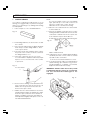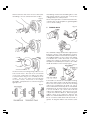
1
37” WOODLATHE
Model No. CWL12D
Part No. 6500680
OPERATING & MAINTENANCE
INSTRUCTIONS
12/97
CONTENTS
PAGE
Lathe Specifications ................................................................................................... 3
General Safety Instructions ........................................................................................ 5
Wood Lathe Safety Instructions ................................................................................. 6
Electrical Connections and Motor Specifications ................................................... 7
Unpacking And Checking Contents ........................................................................ 8
Assembly And Installation .......................................................................................... 9
Understanding your Lathe ....................................................................................... 11
Spindle Speeds and Belt Tensioning ....................................................................... 12
Preparation for use (Spindle/Faceplate/Outboard Turning & Indexing) ........... 13
Using Woodworking Chisels and Basic Techniques ............................................... 18
Making Standard Cuts ............................................................................................. 23
Spindle Turnings ......................................................................................................... 26
Miscellaneous Operations ....................................................................................... 28
Face Plate And Chuck Turnings .............................................................................. 29
Fancy Face Plate Turnings ....................................................................................... 30
Turning Plastics .......................................................................................................... 33
Sanding, Buffing And Polishing ................................................................................ 34
Maintenance ............................................................................................................ 35
Lubrication ................................................................................................................. 35
Optional Accessories ............................................................................................... 36
Spares And Servicing ................................................................................................ 36
Parts List ...................................................................................................................... 37
Parts Diagram ............................................................................................................ 38
2
Thank you for purchasing this CLARKE 37” Wood lathe, designed for DIY and semi professional use.
Before assembling this machine, please read this manual thoroughly and follow all instructions
carefully. In doing so you will ensure the safety of yourself and that of others around you, and you can
GUARANTEE
This CLARKE product is guaranteed against faulty manufacture for a period of 12 months from the
date of purchase. Please keep your receipt as it will be required as proof of purchase. This guarantee
is invalid if the product is found to have been abused or tampered with in any way, or not used for the
purpose for which it was intended.
Faulty goods should be returned to their place of purchase, no product can be returned to us without
WARNING:
THIS MACHINE MUST NOT BE MODIFIED, OR USED FOR ANY PURPOSE
SPECIFICATIONS
Motor .............................................................................................. 230V 50Hz 1Ph
Power Rating ................................ 370W
Switch Type ................................... No Volt Release
Turning Capacity
(Between Centres) ....................... 37 in (940mm)
(Over Bed) .................................... 12 in Dia (305mm)
Spindle Speeds
1. .................................................... 475 RPM
2. .................................................... 838 RPM
3. .................................................... 1374 RPM
4. .................................................... 2215 RPM
5. .................................................... 3260 RPM
Headstock Drive Spindle
Inboard .......................................... a. No. 1 Morse Taper
....................................................... b. External 3/4 UNF thread
Outboard ...................................... External 3/4 UNF Left Hand
thread
Tailstock Spindle ............................................................................ No. 1 Morse Taper
Tailstock Spindle Advance ........................................................... 2 3/8 in (60mm)via hand wheel)
Overall Dimensions (LxWxH) ......................................................... 541/8 x 153/4 x 121/8 in
(1,375x400x308 mm)
3
GENERAL SAFETY RULES FOR OPERATING MACHINERY
WARNING
As with all machinery, there are certain hazards involved with their operation and use. Exercising
respect and caution will considerably lessen the risk of personal injury. However, if normal safety
1.
contained.
KNOW YOUR MACHINE.
Read the manual carefully. Learn the
machines applications and limitations, as
well as the specific potential hazards
peculiar to it.
2.
KEEP GUARDS IN PLACE
and in working order.
3.
EARTH ALL MACHINES.
If the machine is equipped with three-pin
plug, it should be plugged into a three-pin
electrical socket. Never remove the earth
pin.
4.
REMOVE ADJUSTING KEYS AND WRENCHES.
5.
KEEP WORK AREA CLEAN.
Cluttered areas and benches invite
accidents.
6.
DON’T USE IN DANGEROUS ENVIRONMENT.
Don’t use machinery in damp or wet
locations, or expose them to rain. Keep
work area well lit.
7.
KEEP CHILDREN AND VISITORS AWAY.
All children and visitors should be kept a
safe distance from work area.
8.
MAKE WORKSHOP CHILDPROOF
Use padlocks, master switches or remove
starter keys etc.
9.
DON’T FORCE THE MACHINE.
It will do the job better and safer, at the rate
for which it was designed.
12. USE SAFETY GLASSES.
Also use face or dust mask if cutting
operation is dusty. Everyday eyeglasses
only have impact resistant lenses, they are
NOT safety glasses.
13. USE EAR DEFENDERS.
14. DON’T OVERREACH.
Keep proper footing and balance at all
times.
15. MAINTAIN TOOLS IN TOP CONDITION.
Keep tools sharp and clean for best and
safest performance. Follow instructions for
lubricating and changing accessories.
16. ALWAYS DISCONNECT THE MACHINE
before servicing or changing accessories.
17. AVOID ACCIDENTAL STARTING.
Ensure the machine is switched OFF before
plugging in.
18. CHECK FOR DAMAGE.
If part of the machine (eg. A cover or
guard), is damaged, it should be carefully
inspected to ensure that it can perform its’
intended function correctly. If in doubt, the
part should be renewed. Damage to
moving parts or major components should
be Inspected by a qualified technician
before operating the machine. Contact
your local dealer for advice.
19. DO NOT STAND ON THE MACHINE.
Serious injury could occur if the machine is
tipped over. Do not store materials above
or near the machine such that it is
necessary to stand on the machine to get
to them.
10. USE RIGHT TOOL.
Don’t force a tool or attachment to do a
job for which it was not designed.
20. NEVER operate a machine when under the
11. WEAR PROPER APPAREL.
Loose clothing, gloves, neckties, rings,
bracelets, or other jewellery may get
caught in moving parts. Nonslip footwear is
recommended. Long hair should be
4
ADDITIONAL SAFETY RULES FOR WOOD LATHES
1.
IMPORTANT: You should not operate this
machine unless you are thoroughly familiar
with wood turning lathes and wood turning
techniques. If there is any doubt whatsoever,
you should consult a qualified person.
mount the Centre with workpiece attached
into headstock spindle.
2.
Do not operate the machine until it is
completely assembled, and this entire
manual, has been read and understood.
10. When using the Faceplate, ensure the
workpiece is securely fastened to it and
the appropriate size faceplate is used to
correctly support the workpiece. Ensure the
securing screws cannot interfere with the
turning tool at the finished dimension.
3.
Ensure the proper electrical regulations are
followed. The machine must be properly
earthed.
11. ALWAYS rough cut the workpiece as close
as possible to the finished shape before
mounting on to a faceplate.
4.
Before switching the machine ON, ALWAYS:a. Clear the lathe bed of ALL objects
(tools, scraps of wood etc.).
b. Examine the setup carefully, ensuring
nothing could possibly interfere with
the rotating workpiece. eg. The tool
rest is secure and not liable to swing
into the workpiece. Rotate workpiece
by hand to check.
c. Ensure the tool rest is adjusted to the
correct height, and is as close to the
workpiece as possible.
d. Ensure all clamps are properly secured.
e. Ensure your clothing is properly adjusted.
f. Ensure the workpiece is centralised.
12. ALWAYS examine the workpiece for flaws.
Do not use wood which is split or has knots.
Test glued joints before mounting on to
lathe to ensure they have completely set.
5.
14. NEVER attempt to remount a faceplate
turning to the faceplate for any reason.
Never attempt to remount a betweencentres turning if the original centres in the
turning have been altered or removed.
15. ALWAYS clean the machine at the end of a
working session. Remove centres from the
headstock AND tailstock and store them.
Ensure the work area is cleaned before
leaving the machine.
Make all adjustments with the power
OFF.
6.
ALWAYS use the slowest speed when
starting a new workpiece, and cut at
correct speed for material and shape.
7.
ALWAYS remove the tool rest when sanding
or polishing.
8.
When turning between centres, always
ensure that the tailstock centre is snug
against the workpiece, with the spindle
locked, AND the Tailstock securely locked
to the bed. NEVER loosen the tailstock
spindle OR the tailstock with the workpiece
turning.
NOTE: The centre should be lubricated
(unless it is a ball bearing type).
9.
13. When roughing off, DO NOT jam tool into
workpiece or take too big a cut.
16. Should any part of the lathe be missing,
damaged, or fail in any way, or any
electrical component fail to perform
properly, shut OFF the machine and
disconnect from the power supply. Replace
missing, damaged or failed parts before
resuming operation. If in doubt, consult
your local dealer. Always disconnect from
power supply when carrying our repairs.
17. Be particularly careful with your clothing
when operating a lathe. Always wear
safety glasses. Long hair should be
contained. See General Safety Instructions
- Apparel.
18. Do not exceed recommended speeds.
Refer to chart on page 12
DO NOT drive the workpiece into the
centre when the centre is installed in the
headstock. Always set the workpiece into
the centre with a soft mallet first, and then
5
ELECTRICAL CONNECTIONS
Connect the mains lead to a standard 230 volt (50Hz) electrical supply using a 13 amp BS1363 plug
fitted with a 13 amp fuse. or a suitably fused isolator switch.
WARNING : THIS APPLIANCE MUST BE EARTHED.
IMPORTANT : The wires in the mains lead are coloured in accordance with the following code :
Green & Yellow
-
Earth
Blue
-
Neutral
Brown
-
Live
As the colours of the flexible cord of this appliance may not correspond with the coloured markings
identifying terminals in your plug, proceed as follows :Connect GREEN & YELLOW coloured cord to plug terminal marked with a letter “E” or Earth
symbol ‘ ’ or coloured GREEN or GREEN & YELLOW.
Connect BROWN coloured cord to plug terminal marked letter “L” or coloured RED.
Connect BLUE coloured cord to plug terminal marked letter “N” or coloured BLACK.
We recommend that this unit is fitted with a Residual Current Device (RCD)
FUSE RATING
The fuse for the plug in this appliance must be rated at 13 amps.
MOTOR SPECIFICATIONS
The five speed pulley system of this lathe is designed to use a 1725 RPM, 370W motor. Rotation is
clockwise as viewed from the pulley end of the shaft. It is wired for 230 Volt, 50Hz.
Caution: Do not any other type of motor as their use may be hazardous.
The machines’ ON and OFF buttons are marked “I” for ON and “O” for OFF.
Should the power fail whilst the machine is in use, the NO VOLT RELAY will operate. This is a safety
feature which prevents the machine from starting up automatically when the power is restored. It
6
UNPACKING AND CHECKING CONTENTS OF CARTON
Your wood lathe is shipped complete in one carton.
Separate all parts from packing materials and check against the lists below to ensure that all items
are accounted for, before discarding any packing material.
If any parts are missing or damaged in any way, please contact your Clarke dealer immediately.
Fig. 1
A. Head stock assembly.
B.
Includes : Drive spindle, motor, drive belt,
pulleys (2), pulley guard, spindle nut, ONOFF switch , power cable, and outboard
spindle cover.
Bed. (1- Headstock End, 2 - Foot End)
E.
Tailstock assembly
F.
Tool rest bracket
G. Tool rest base
H.
Tool rest -12"
J.
Tool rest - 6"
C. Foot
K.
Faceplate - 4"
D. Bed Clamping bolt
Also included but not shown - one bag
containing loose parts and tools,listed below.
TABLE OF LOOSE PARTS
L.
Fig. 2
Locking handle assemblies (4 pcs)
M. Tool rest locking handle
N. Mounting bolts c/w nuts and washers (4pcs)
O. Tool rest bracket securing bolt
P.
Brass slugs (2 pcs)
Q. Screw (countersunk head)
R.
Flat washer
S.
31/2” Bolt c/w nut and washers
T.
1
U.
Spur Centre
V.
Revolving Centre
/2” Pan head wood screws (3 pcs)
W. Hex. wrenches (2 pcs)
7
ASSEMBLY AND INSTALLATION
Ref. Figs. 1 & 2
To carry out this alignment, first align the two
keys by eye as close as possible. Next, using
a metal straight edge against one side of
the keys, slide the end of the straight edge
across the joint first from one side of the joint
and then from the opposite side. If there is
a “click” or a hang-up of the straight edge
at the joint, it will be obvious what relative
direction the two halves of the bed will have
to be rotated to achieve alignment.
Repeat this process as many times as
necessary, on both sides of the key, to be
satisfied tha alignment has been attained.
1. MOUNTING HEADSTOCK TO BENCH
1.1 Drill two 10mm holes in your bench or stand
according to diagram, Fig. 3.
Note: Make sure the top of your bench is
positioned so that your don’t drill into the legs or
rail underneath.
1.2 Position the headstock assembly (A) on the
bench and insert two 5/16" x 2" carriage
bolts through the two mounting holes in the
base. Place a flat washer, a lock washer
and a nut from the underside on each bolt.
Tighten nuts - only finger tight at this time.
When satisfied, screw in the single
countersunk headed screw (Q), through the
hole in the key and into the tailstock end so
that the two halves of the bed are now
secured.
Fig.3
2.4 Nip up the Bed clamping bolt (but do not
fully tighten), so that when the foot is placed
on the bench, the key is facing downwards.
3. ASSEMBLY OF BED TO HEADSTOCK
3.1 Slide the tail stock assembly (E), and the tool
rest base assembly (G), on to the bed as
shown in Fig. 10.
2. ASSEMBLY OF LATHE BED HALVES.
Ensure the Clarke label on the Tailstock and
the threaded hole in the tool rest base
(shown in fig 4), faces towards the front.
2.1 Assemble the two bed halves (steel tubes)
together by inserting the Headstock end
(the tube with the plugged end carrying the
threaded hole in the centre of the plug),
into the machined inside diameter of the
Tailstock end .
Fig.4
2.2 Insert the ‘V’ shaped portion of the foot (C),
into the open, exposed Tailstock end and
then insert the bed clamping bolt (D)
,
through the foot and into the threaded hole
in the plugged headstock end. Start the
thread but do not tighten at this time.
3.2 Now insert the bed assembly into the
headstock assembly (A), fully, and
manoeuvre the lathe so that the bed is
parallel to the front edge of the bench.
NOTE: It may assist by turning the complete
bed assembly on its end to locate the long
bolt into the threaded hole in the end of
the headstock bed end.
4. SECURING THE LATHE TO THE BENCH
4.1 Mark the position of the two Foot mounting
holes and drill two 10mm holes in the bench.
2.3 Align the two keys (the strips of metal
attached to each bed half with screws) so
that they line up exactly. This alignment is
necessary so that the Tail Stock Assembly
(E), and the Tool Rest Base (G), will slide freely
over the joint formed by the two halves of
the bed.
4.2 Insert the Foot mounting bolts, and shake
the complete assembly to ensure it is stable
and lying flat on the bench. When satisfied,
nip up all four mountings - finger tight only.
REMEMBER At this stage the bed clamping
bolt must not be tight.
8
If the bed is too loose however, the weight
of the Tailstock and Tool rest base may
cause the bed to rotate. In this event, nip
`up the Bed Securing Set Screw (T, fig 10).
Fig. 5
4.3 For additional rigidity of the motor and it’s
mounting brackets, a 8mm hole must be
drilled through the bench top using the hole
in the hinge bracket (V, fig 10), as a pilot. It
will be necessary to remove the four
mounting bolts and moving the headstock
slightly to facilitate the drilling of the hole.
The wrench provides a quick release type of
attachment, so that the tool rest can be moved
quickly to a new position. eg. As the diameter
of the workpiece decreases, the tool rest must
be moved to maintain an acceptable
clearance between it and the work. (This
adjustment MUST be carried out with the
machine switched OFF)
Locate 1/4" x 3 1/2” long hex. head bolt in
the bag of loose parts together with 2 plain
flat washers, a spring lock washer and a nut.
Place a plain flat washer on to the bolt and
insert the bolt through the hinge bracket
hole and on through the bench top. From
the underside of the bench, place a plain
flat washer, the spring lock washer and then
the nut, on to the bolt. Do not tighten fully.
6. ADJUSTING THE TAIL STOCK TO THE BED
The tailstock supports the workpiece for spindle
turning, that is, turning between centres.
4.4 Next, secure the belt guard to the bench
with wood screws. Open the blade guard
cover to reveal three holes in the bottom
flange of the plate. Locate three 1/2 inch
long pan head wood screws in the bag of
loose parts. Ensure the plate is parallel to the
belt and the cover opens and closes easily
then screw in the wood screws loosely.
To prevent it from rocking during operation a
screw is provided at its base (see fig. 6), which
bears against the keyway on the underside of
the bed, thereby reducing the play between
the key and the tailstock keyway.
To carry out this adjustment, proceed as follows
Tighten down the adjusting screw moderately
against the keyway, then slacken off about 1/4
turn.
4.5 Gently shake the complete assembly to
ensure it is stable and lying flat on the bench,
and when satisfied, tighten the four
mounting bolts followed by the motor
bracket securing bolt and the three wood
screws, fully.
Slide the tailstock along the full length of the bed.
If it binds or sticks in any one spot, loosen the
adjusting screw only enough so that the tail stock
slides smoothly. If the tail stock feels loose and
can be rocked slightly, tighten the screw only
enough so that it will not bind when sliding the
full length of the bed.
5. COMPLETING THE ASSEMBLY
The 4 locking handles are used to lock the
Tailstock and the Tool Rest base to the bed, the
Tool Rest to its bracket, and to lock the Tailstock
spindle to prevent it from moving during
operation.
When both conditions have been met, tighten
the lock nut.
Fig. 6
Before screwing the handles in place, ensure
that a brass slug is inserted in each of the holes
where the Tailstock and the Tool Rest base are
secured to the bed. i.e. the threaded hole
shown in the tool rest base in Fig. 4, and the
tailstock locking handle hole. (see fig. 6).
Finally, place the tool rest bracket on top of the
tool rest base and screw the bolt with flat washer
and wrench (as arranged in fig 5), through the
slot in the bracket and into one of the holes in
the base.
9
5. ALIGNING THE CENTRES
6. REMOVAL OF SPUR CENTRE FROM
SPINDLE
5.1 The spur centre and the revolving centre
are used for spindle turning and should
always be in alignment. To align centres
refer to Fig. 7 and adjust as follows:
To remove the spur centre from spindle, hold the
spindle pulley with one hand whilst turning the
spindle nut on the threaded portion of the
spindle, with a spanner, anticlockwise until the
centre is ejected.
5.2 Insert spur centre into head stock spindle
and revolving centre into tailstock spindle.
Note: Do not drive or hammer centres into
their spindle’s as it is completely
unnecessary, and removal may be difficult.
Simply tap them home with a piece of
wood.
Fig. 7
Fig. 8
7. REMOVAL OF REVOLVING CENTRE
To remove revolving centre from tail stock
spindle, insert a 6mm dia. rod through the hole
in the tailstock spindle. Hold the centre with one
hand and tap the rod with a hammer.
Slide the tailstock toward the headstock so
that the two points of the centres are very
close but not touching. Tighten the tailstock
lock.
Loosen the bed clamping bolt (D), in the
foot, about two turns.
Fig. 9
Using a 3/16 hex wrench (supplied), loosen
the bed securing set screw, located on the
back of the head stock (T, fig. 10).
Swing the tailstock so that the points of the
Centres coincide perfectly, then tighten the
bed securing set screw and the bed
clamping bolt (D), firmly.
10
UNDERSTANDING YOUR LATHE
LATHE PARTS, CONTROLS, NOMENCLATURE AND FUNCTIONS
Become familiar with the nomenclature and purpose of the various operating controls and parts of
your lathe. Please read and fully understand this manual before attempting to perform any operation.
Fig. 10
J.
HEX. NUT. Used for the removal of the Spur
Centre.
K.
SPUR CENTRE.
L.
TOOL REST BRACKET LOCK. Clamps the tool
rest bracket to the tool rest base.
M. TOOL REST LOCK. Clamps the tool rest to the
tool rest bracket.
N. TOOL REST BASE LOCK. Clamps the base
and hence the complete tool rest assembly
to the bed.
O. TAILSTOCK SPINDLE LOCK. Locks the spindle
in position during operation.
P.
A. HEADSTOCK
B.
BED
TAILSTOCK LOCK. Clamps the tailstock to the
bed.
Q. HAND WHEEL. Adjusts the tailstock spindle.
C. TAILSTOCK
R.
ROTATING CENTRE.
D. TOOL REST
S.
INDEX PIN. Engages with the spindle pulley
to produce equal spacing for various
operations such as fluting, reeding or for
dividing face plate work. DO NOT use to
remove the Centre.
E.
ON BUTTON (I)
F.
OFF BUTTON (O)
G. BELT GUARD LOCK. Ensures the cover is
locked during operation
H.
WARNING LABEL. Essential instructions which
should be complied with.
I.
OUTBOARD SPINDLE END COVER. Protects
the operator from rotating outboard end of
the spindle when not being used for
outboard turning.
This pin MUST be DISENGAGED for normal
operations.
11
T.
BED LOCKING SCREW. Hex socket head
screw.
U.
MOTOR BRACKET MOUNTING HOLE.
V.
DRIVE BELT ADJUSTER.
SPINDLE SPEEDS
A chart showing spindle speeds and recommended turning speeds is mounted on the pulley cover,
and for convenience, is duplicated as follows:
SPINDLE SPEEDS
RECOMMENDED GENERAL SPEEDS
SPINDLE TURNING
SQUARE
LENGTH
ROUGHING
FINISHING
1” (25mm)
12” (305mm)
1374
3260
2” (50mm)
18” (455mm)
838
2215
3” (75mm)
24” (610mm)
838
2215
4” (100mm)
30” (760mm)
475
2215
5” (125mm)
36” (915mm)
475
2215
FACE PLATE TURNING
DIAMETER
THICKNESS
ROUGHING
FINISHING
12” (305mm)
4” (100mm)Max.
475
1374
10” (255mm)
4” (100mm)Max.
838
2215
8” (205mm)
4” (100mm)Max.
1374
2215
6” (150mm)
4” (100mm)Max.
2215
3260
Fig. 11
If you wish to run at a slower speed, say 1374
RPM, you must shift the belt inwards, 1 step.
CAUTION : MAKE SURE THE POWER CORD IS
REMOVED FROM THE OUTLET BEFORE
ATTEMPTING TO CHANGE THE BELT POSITION.
BELT TENSION ADJUSTMENT
Belt tension is provided by the weight of the
motor pivoting the motor mounting bracket
downward through the “hinge” of the hinge
bracket. To increase the belt tension, screw in
the adjustment bolt located in the corner of the
motor mounting bracket (V, fig. 10), thus
restricting downward pivoting travel.
Conversely, loosening the adjusting bolt allows
increased pivot on the bracket thus decreasing
belt tension.
Fig.11 shows the belt positioned on the second
step from the outside edge of the pulley. This
produces a spindle speed of 2215 RPM. (Refer
to the chart above).
12
PREPARATION
1. SPINDLE TURNING
NOTE:
If you use a ‘dead centre’ i.e not a rotating
type, put a drop of oil or wax on the wood
where it contacts the centre. This will
lubricate the wood whilst it is turning.
If you are not experienced at the art of wood
turning, we suggest that you practice using the
various wood turning tools, starting with turning
a small spindle.
1.8 Place the wood between the centres and
lock the tailstock.
1.1 Select a piece of wood 50x50x305mm.
1.9 Move the rotating centre into the wood by
turning the tailstock hand wheel. Ensure the
centres are “seated” into the wood, into the
holes made in steps 5 and 6 above.
Fig. 12
Rotate the wood by hand whilst turning the
Fig. 14
1.2 Draw diagonal lines on each end to locate
the centres.
1.3 On one end, make a saw cut approximately
2mm deep on each diagonal line. This is
for the spur centre.
1.4 The other end is the rotating centre. Place
the point of the centre on the wood where
the diagonal lines cross.
tailstock hand wheel.
5.10 Adjust the tool rest so that it is approximately
1/8" away from the corners of the wood and
1/8" above the centre line.
1.5 Drive the centre into the wood. Use a
wooden mallet or a plastic hammer, but put
a piece of wood on the end of the centre
to protect it.
Lock the tool rest base and the tool rest.
5.11 Consult the speed chart. Note that a 50mm
square turning, up to 455mm long, should
run at 838 RPM for “roughing”. Check and
adjust the drive belt if necessary.
Fig. 13
Wooden Mallet
or
IMPORTANT. ALWAYS rotate the wood by hand
to guarantee that the corners do not strike the
tool rest, and that the indexing pin is not
engaged.
Fig. 15
1.6 Remove the rotating centre and drive the
spur centre into the other end of the wood.
Make sure the spurs are in the saw cuts.
Remove the spur centre.
1.7 Make sure the centres and the hole in the
spindle and the tailstock spindle are clean.
Insert the spur centre into the headstock
and the rotating centre into the tailstock
and tap them in lightly with a piece of wood.
DO NOT DRIVE THEM IN.
13
5.12 Check to ensure there are no spanners/
wrenches/pieces of wood or other debris
in the area, and that your clothing is
properly adjusted before pushing the ON
button.
3. INDEXING
Fig. 17
The procedure for cutting and the use of
woodworking chisels is described under “Using
Woodworking Chisels, starting on page 15. See
also ‘Spindle Turning’ on page 24.
2.
FACEPLATE TURNING
Turning which cannot be worked through
centres, must be mounted on a faceplate, or
other work-holding device. (Some jobs may
require the use of special chucks).
The spindle pulley contains 36 equally spaced
holes. The index pin engages with these holes
to keep the spindle from turning whilst you put a
mark on the workpiece.
All face plate work is done by scraping. Any
attempt to use a cutting technique on edge
grain, will result in hogging or gouging, which
may tear the tool out of your hands.
For example, to locate the position of six spokes
in a wheel :
2.1 Pull the index pin outward and turn it so that
the small cross pin slips into the slot. This will
allow the index pin to engage in one of the
holes in the pulley and prevent the spindle
from turning.
For Faceplate turning, the work (suitably trimmed
so that it is as near to its final dimension as
possible), should be firmly mounted on to the
faceplate, using screws as appropriate (see fig
16).
The complete assembly is then screwed on to
the headstock spindle, and tightened securely,
by holding the faceplate, and turning the
spindle nut using a 27mm or 1-1/16 AF spanner,
to lock it up against the faceplate boss.
2.2 Adjust the tool rest approximately at the
centre line of the workpiece and make a
mark.
Fig. 18
Fig. 16
The screws used in securing the work to the face
plate, must not be of sufficient length as to
interfere with the tool at the final dimension. It
may be necessary to screw the work to a
backing piece, depending upon design, or
where screws are not permissible at all, the work
may be glued to a backing piece, fitting a piece
of paper at the joint, which will allow for later
separation without damaging the wood.
14
2.3 Pull out the index pin and slowly rotate the
workpiece until the pin slides into the next
hole in the pulley.
3. OUTBOARD TURNING
This technique is used to do jobs that are too
large to mount conventionally. It is straight
forward faceplate turning except that because
of the work size, extra caution must be taken
and speeds must be restricted to minimums.
2.4 Do this six times and put the next mark on
the workpiece. The two marks will be
spaced 60° apart. Continue this operation
until six spokes are marked 60° apart.
In order to perform outboard turning operations,
you must first build a stand similar to the one
shown in Fig. 19. This is no more than a tool rest
support.
2.5 Spindle turning can be divided in the same
manner.
WARNING: The indexing pin must be disengaged
for all other operations on the lathe.
Ensure that the top-to-floor distance allows you
place the chisel on the work centre line.
Fig. 19
DO NOT PUSH THIS SUPPORT WHEN CUTTING.
DO NOT TRY TO MOUNT WORK SO LARGE THAT
THE MOTOR MUST STRAIN TO TURN IT.
IF YOU WISH TO EXPERIMENT WITH THIS
TECHNIQUE DO SO WITH SOFT WOODS - LET THE
HEAVIER, HARDER WOOD COME LATER.
The outboard end of the spindle is under the
pulley cover and is protected by a plastic cap.
This end is provided with a left hand thread
which will accept available face plate
accessories .
Remove the protective cap, and screw on the
face plate with workpiece attached. (See face
plate turning on page 26).
15
USING WOODWORKING CHISELS
Fig. 20
THE SIX MOST COMMONLY USED CHISEL TYPES
1. SELECTION OF CHISELS
Cutting is faster than scraping and produces a
smoother finish which requires less sanding.
However, it is far more difficult to master.
Scraping, on the other hand, is far more precise
and easier to control.
Better chisels have handles approximately 10"
(250mm) long, to provide plenty of grip and
leverage. Sharp tools are essential for clean,
easy work. Buy tools that will take and hold keen
edges.
2.2 When You Can Cut and When You Must
Scrape.
Fig. 22
An 8 piece chisel set is available from your
CLARKE dealer, part no. 6500649
2. THEORY OF TURNING
There are two classes of chisel; these are :
a.
Chisels intended primarily for cutting, and
b.
Chisels used only for scraping.
The cutting chisels are the gouge, skew and
parting tool. These are most commonly used.
They are sharpened to a razor edge by honing
on both sides.
The scraping chisels are the flat nose, round nose
and spear point. These are not honed on the
flat sides, the wire edges produced by grinding
are left on to aid in the scraping process.
There are two different types of cut to consider
when turning.
One is cutting at the circumference of the
workpiece (for example, turning down the outer
surface of a cylinder or the inner wall of a hollow
round box, as shown in fig. 23). In this approach
the surface being turned travels under the chisel
edge like an endless belt.
Fig. 21
The second type is cutting at the diameter of a
workpiece (as when turning the face of
faceplate turning or the side of a large shoulder
on a spindle turning, as shown in fig. 23). In this
approach the surface being turned rotates like
a disc under the chisel edge. Sometimes the
approach will be a combination of both.
Cutting Chisel Scraping Chisel
2.1 Cutting and Scraping
To cut, the chisel is held so that the sharp edge
actually digs into the revolving work to peel off
a shaving.
Fig. 23
To scrape, the chisel is held at a right angle to
the work sur face as shown in fig. 22, and
removes fine particles instead of shavings.
Many operations require that the cutting chisels
be used for scraping, but scraping chisels are
never used for cutting. Scraping dulls a chisel
must faster, especially the razor sharp cutting
chisels.
18
Either a cutting or scraping action can be used
when cutting at the circumference. The shaving
is removed like a peeling from a potato.
difficulty holding the
chisel,
then
the
improperly supported
chisel will begin to
bounce, or chatter,
against the workpiece.
Scraping only, is used when cutting at the
diameter. The reason is obvious when you
consider that faceplate turning always requires
removal of wood across the grain. Wood does
not peel easily across the grain, and attempts
to use a cutting method will result in damage to
the work and throwing of the chisel by the work.
If the rest is placed too
low, the chisel must be
held extremely high to
position the bevel
against
the
work
(Sketch 3). Then the rest
loses most of its value as
a fulcrum, and the
downward force of the
revolving workpiece
tends to kick the chisel
back out of your hands.
It follows that a cutting action is used for the
majority of spindle turning operations, whilst the
majority faceplate turning is done by the
scraping method.
When a combination approach is to be used,
you will have to judge, by the feel of the work,
when to stop cutting and start scraping.
Never try to cut when it becomes difficult to hold
the chisel against the roughness of the wood
grain.
If the rest is placed too
high, (Sketch 4) and the
chisel is correctly
positioned for cutting, it
strikes the workpiece
near the top where the
direction of force
exerted
by
the
workpiece is nearly
horizontal,
and
kickback will again
result.
2.3 How To Position The Tool Rest for
Circumference Cutting
When cutting, the object is to pierce the outer
skin of wood to a certain desired depth, then to
hold the chisel steady, with the bevel edge
parallel to the work circumference, so that it will
peel off a shaving at this desired depth.
The only sure method of holding the chisel
steady is to rest the bevel against the work, as
shown in sketch 1.
When the tool rest is at
the proper height , the
chisel can be held with
the bevel pressed
against the work, and
the tool rest will act as a
fulcrum to support the
chisel against the
downward force of the
revolving work.
If the rest is placed too
far out from the work
surface (Sketch 5) then,
when correctly held, the
chisel is again too high
on the work. Also, you
have less leverage on
your side of the tool rest,
and it is even more
difficult to hold the
chisel.
With large diameter
work (Sketch 6), the tool
rest can be above the
workpiece centre line,
and somewhat out from
the work surface.
If the rest is placed too
low, so that the chisel is
held with the bevel out
from the work (Sketch
2), the cutting edge will
continue to dig deeper
into the work. It will dig
in until the “bite”
becomes so deep that
your
hands
have
With small diameter
work (Sketch 7), the rest
should not be far from
the work surface. As
work grows smaller, the
rest
should
be
19
2.4 How to Position Tool Rest for
Circumference Scraping
Fig. 26
In scraping operations, the tool rest position is
not as critical as it is for cutting operations. The
chisel generally is held horizontally, though it can
be held at an angle to reach into tight places.
Considering that the wire edge of the chisel
does the scraping, sketches 9 and 10 show the
results of too low or too high a position for the
rest, and sketch 8 shows the chisel action with
the rest correctly positioned.
Fig. 24
Three gouges the 1/4”, 1/2”, and 3/4” are ample
for general DIY turning, but other sizes from 1/8”
to 2” can be purchased.
The main use of the gouge is for rough
circumference cutting of raw stock down to a
cylinder of working size. it is the best tool to use
for rapidly cutting away large areas of the
workpiece, but when so used does not produce
a smooth surface. With practice, it can be used
for cutting coves and the shaping of long cuts.
It is also useful for scraping.
When used for cutting, the gouge is always held
with the convex side down. It should be rolled
approximately 30° to 45° in the direction in which
it is being advanced along the rest, and the
cutting edge will be a little in advance of the
handle.
2.5 How to Position Chisel and Rest for
Diameter Scraping
Fig. 25
When scraping on the diameter, that portion of
4. USING THE SKEW
27
Two skews, the 1/2 and 3/4” sizes, areFig.
all that
are needed for general use. Other sizes are
surface to the right of centre is moving upwards
(Sketch 11). If the chisel is placed in this area, it
will simply be carried up off the rest and out of
your hands. All diameter scraping operations
must be done at the left of centre.
Three different chisel contact points are shown
in Sketch 12. It will be noted that, when the chisel
is above the workpiece centre, or below it, the
work surface sweeps past the chisels’ edge at
an angle and tends to carry the chisel in one
direction or the other along the rest. Only when
the chisel contacts the work on the centre line
does the work surface pass squarely under the
chisels edge. This then, is the position in which it
is easiest to hold the chisel steady. To obtain
this position, place the rest approximately 1/8"
(3mm) - thickness of chisel, below the centre.
available. This tool is nearly always used to make
finished cuts, to cut vees and beads, and to
square shoulders. Properly used, it produces the
best finish that can be obtained with a chisel. it
should not be used for scraping, as this quickly
dulls it.
For finish cutting, the skew is held with the cutting
3. USING THE GOUGE
20
bevel side down, keep the base of the bevel
against the work. Good practice is to place the
skew well over the work, pull it back until the
edge begins to cut, then swing the handle into
position to advance the cut. Both the toe and
the heel of the skew can be used for taking
light cuts, but do not penetrate the wood too
deeply without cutting clearances, as there is
danger of burning the tip of the tool.
The spear point is used for fine scraping and
delicate operations, such as the forming of
beads, parallel grooves and shallow vees. Edges
and bowl contours can be rounded with the
round nose chisel. Any flat surface can be
scraped with the flat nose chisel.
7.
USING SHAPER OR MOULDING KNIVES
Fig. 30
5. USING THE PARTING TOOL
The parting tool has just one primary purpose to
cut straight into the workpiece as deep as
Fig. 28
An old chisel can be made to serve as a holder
for ‘shaper’ or ‘moulding’ knives. Such knives
make it possible to scrape many interesting
shapes in the workpiece surface in one or two
operations instead of the many operations
required with standard chisels. It is generally not
practical to use cutting methods with special
shape tools, scraping methods should be used.
desired, or all the way through to make a cutoff, it is therefore a very narrow tool. 1/8 inch
wide and shaped to cut its own clearance so
that the edge will not be burned. When used
for scraping, however, it should be backed off
regularly to prevent overheating.
The holder should provide a shoulder against
which the butt end of the knife can be firmly
seated, and the knife must be securely
mounted, either by means of a screw threaded
into the holder, or be compressing it between
two prongs bolted together.
Unlike the gouge and skew, the parting tool is
seldom held with the bevel against the work.
As the amount of stock removed is small, a
support for the bevel is not necessary. The tool
is simply fed into the work at an angle (for
cutting), or pointed at the workpiece centre (for
scraping) it can be held easily in one hand.
8. USING A BLOCK PLANE
Fig. 31
6. USING THE SCRAPING CHISELS
Fig. 29
Clear glass smooth finishes (especially on soft
woods) can be obtained by using a block plane
set to take a fine shaving. The tool rest should
be raised up approximately to the top of the
workpiece, and the plane should be horizontal,
but turned slightly in the direction of travel so
that it will take a shearing cut. Two tool rests,
one in front and the other behind the work, can
be used to advantage in positioning the plane
so as to exactly limit the depth of cut (and
finished size of the workpiece).
A 1/2” wide spear point chisel, a 1/2” wide round
nose chisel and a 1” wide flat nose chisel
complete the list of tools ordinarily used by home
craftsmen. Each of these scraping chisels can
be purchased in various other sizes for special
purposes. All are very useful for diameter
scraping operations and for circumference
scraping, when cutting methods cannot be
employed.
21
10.2
9. USING WOOD RASPS AND FILES
Finish Cutting
Fig. 32
Finish cutting requires more control with less force
and is better done with the palm of the tool rest
hand turned up. The wrist is still held down, and
the side of the index finger acts as a guide along
the rest. In this position, control of the chisel is
shared by both hands, the fingers of the tool rest
hand being free to assist in positioning the tool.
A wood rasp will remove stock quickly when held
against the revolving workpiece. Care should
be taken to support the rasp firmly against the
tool rest however, as it can tear the hands
painfully if caught by a rough edge of the
workpiece and kicked back. The rasp will leave
a very rough finish.
10.3
Finer finishes (similar to those produced by
scraping), can be obtained by using files in the
same manner. Various shape files can be used
for shaping vees, beads, coves etc. If pressed
into the wood too hard, however, a file can burn
the workpiece surface. Keep the file clean to
keep it cutting uniformly. Files work best on hard
woods.
Intricate Cutting
Fig. 35
Intricate, delicate cutting requires extreme
control, with practically no force. This is best
accomplished by guiding the chisel with the
fingers of the tool rest hand. The hand is held
palm up, with the wrist high, and the little finger
placed against the rest to steady the hand. The
chisel does not touch the rest and the handle
hand is completely secondary to the tool rest
hand.
The first and second positions are equally good
for scraping operations, but the third position is
never used for scraping.
10. HAND POSITIONS
When handling a chisel, the hand takes a
natural position, being nearer or farther from the
end depending upon the amount of leverage
required. The position of the tool rest hand is a
matter of individual liking, but there are three
generally accepted positions, each best for
certain types of operations.
10.1
Fig. 34
Roughing Off
11. CUTTING TO DEPTH
Fig. 33
Fig. 36
Many scraping operations and cutting to depth
with the parting tool can be easily done with
one hand. The chisel is grasped firmly with the
index finger on top, to press it down against the
rest, and is thrust straight into the work. Holding
the tool thus leaves the other hand free to hold
a pattern , callipers etc., to check work progress.
Roughing off and other heavy work requires a
firm grip and solid positioning of the chisel
against the rest. This is best obtained by the tool
rest hand position as illustrated. The wrist is
dropped down so that the heel of the hand
below the little finger acts as a sliding guide
against the rest. The handle hand controls chisel
position.
22
MAKING STANDARD CUTS
end can also be taken. Roughing-off generally
is continued until the cylinder is approximately
3mm larger than the desired finished size.
Roundness can be tested by laying the gouge
on top of the work - it will not ride up and down
when cylinder is perfectly round.
1. THE ROUGHING OFF-CUT
Reducing a square or odd shaped workpiece
down to a cylinder of approximate size for finish
turning is called roughing-off. Faceplate
turnings and large diameter spindles should first
be partly reduced by sawing , but small spindles
are easily turned down entirely with the large
(3/4”) gouge.
Fig. 37
Start the first cut about 50mm from tailstock and
2. ROUGH-CUTTING TO SIZE
The roughing-off cut can be made to accurately
Fig. 37
then run it toward the tailstock and off the end
of the workpiece.
size the cylinder to a given diameter.
Next, start another cut 50mm nearer the
headstock and run it also toward tailstock to
merge with first cut.
Another method is to make a number of sizing
cuts at intervals along the work, then use the
gouge to reduce the whole cylinder down to
the diameter indicated by these cuts.
Continue in this manner until 50mm to 100mm
from the headstock end, then reverse the
direction of tool travel and work one or two cuts
in succession toward the headstock and off this
end of the workpiece.
3. MAKING SIZING CUTS
Sizing cuts are useful to establish approximate
finish-size diameters at various points along a
workpiece. The work can then be turned down
to the diameters indicated and be ready for
finishing.
Never start a cut directly at the end. If the chisel
catches the end, it will damage the workpiece.
Never take long cuts while corners remain on
the work, as this tends to tear long slivers from
the corners.
Fig. 37It
The first series of cuts should not be too deep.
Diameters for sizing cuts should be planned to
be about 3mm greater than the desired finished
diameters.
A sizing cut is made with the parting tool.
Hold the tool in one hand and use the other
hand to hold an outside calliper, preset to the
desired sizing-cut diameter.
As the cut nears completion, lower the chisel
point more and more into a scraping position.
When the callipers slip over the workpiece at
the cut, the cut is finished.
is better to partially reduce the work to a cylinder
along its complete length, then start a second
series of cuts to reduce it to a cylinder. Once a
cylinder has been formed, step the lathe up to
its next fastest speed. Further reductions in size
can now be carried out by cutting as deeply
as desired at any spot along the work.
4. SMOOTHING A CYLINDER
The final 3mm can be removed in two ways.
Either use the 3/4” skew, working from the centre
toward both ends and taking lighter and lighter
cuts until finished.
At this stage long cuts from the centre of either
23
heel of the skew into it along the surface of the
outside area.
Tilt the cutting edge with handle raised up, so
that only the extreme heel does this cutting. If
the shoulder is at the end of work, the process is
called squaring the end. In this case, reduce
outer portion to a diameter about 6mm larger
than tool centre diameter, then later saw off the
waste stock.
5. CUTTING A SHOULDER
A shoulder can be the side of a square portion
left in the workpiece, the side of a turned section
or the end of the workpiece. Most shoulders are
perpendicular to the work axis, but a shoulder
can be at any angle desired.
Fig. 40
6. CUTTING VEES
Vee grooves can be cut with either the toe or
heel of the skew. When the toe is used, the
cutting action is exactly the same as in trimming
a shoulder, except that the skew is tilted to cut
at the required bevel. Light cuts should be taken
first on one side then the other, gradually
enlarging the vee to the required depth and
width.
Fig. 42
First, mark position of the shoulder with a pencil
held to the revolving workpiece. Then make a
sizing cut with the parting tool, placing this cut
about 2mm outside the shoulder position and
cutting to within about 3mm of the depth
desired for the area outside of the shoulder.
If shoulder is shallow, the toe of the skew can be
used to make the sizing cut, but do not go in
deeper that 3mm with the skew unless wider and
wider vees are cut to provide clearance for this
tool.
Fig. 41
When the heel is used, the skew is rotated down
into the work, using the rest as a pivot.
Otherwise, the cutting position and sequence
of cuts is the same.
As when using the toe, it is important that cutting
be done only by extreme end of cutting edge.
If deep vees are planned, it is quicker to start
them by making a sizing cut at the centre of
each vee. Vees can also be scraped with the
spear point chisel or a three-sided file.
7. CUTTING BEADS
Use the gouge to remove any waste stock
outside of shoulder, and smooth this section up
to within 3mm of the shoulder in the usual
manner. Finishing of the shoulder unless it is more
than 25mm high is best done with the 1/2” skew.
First, the toe of the skew is used to remove
shavings from the side of the shoulder, down to
finish size. Hold the skew so the bottom edge of
the bevel, next to shoulder, will be very nearly
parallel to side of shoulder, but with the cutting
edge turned away at the top, so that only the
extreme toe will do the cutting.
If the cutting edge is flat against the shoulder,
the chisel will run. Start with the handle low, and
raise handle to advance toe into the work.
Cut down to finished diameter of outside area,
then clean out the corner by advancing the
This requires considerable practice.
First, make pencil line to locate the tops (highest
points) of two or more adjoining beads. Then
make a vee groove at the exact centre
between two lines, and down to the desired
depth of the separation between the beads.
Be careful not to make the groove too wide or
you will remove portions of the desired beads.
The sides of the two adjoining beads are now
cut with the heel of the skew, preferably 1/2”
size, unless beads are quite large. Place the
skew at right angles to the work axis, flat against
the surface and well up near the top. The
extreme heel should be just inside the pencil line
that marks the top of the bead.
24
MAKING STANDARD CUTS
At this stage long cuts from the centre of either
end can also be taken. Roughing-off generally
is continued until the cylinder is approximately
3mm larger than the desired finished size.
Roundness can be tested by laying the gouge
on top of the work - it will not ride up and down
when cylinder is perfectly round.
1. THE ROUGHING OFF-CUT
Reducing a square or odd shaped workpiece
down to a cylinder of approximate size for finish
turning is called roughing-off. Faceplate
turnings and large diameter spindles should first
be partly reduced by sawing , but small spindles
are easily turned down entirely with the large
(3/4”) gouge.
Fig. 37
2. ROUGH-CUTTING TO SIZE
Fig. 37
Start the first cut about 50mm from tailstock and
then run it toward the tailstock and off the end
of the workpiece.
The roughing-off cut can be made to accurately
size the cylinder to a given diameter.
Next, start another cut 50mm nearer the
headstock and run it also toward tailstock to
merge with first cut.
Another method is to make a number of sizing
cuts at intervals along the work, then use the
gouge to reduce the whole cylinder down to
the diameter indicated by these cuts.
Continue in this manner until 50mm to 100mm
from the headstock end, then reverse the
direction of tool travel and work one or two cuts
in succession toward the headstock and off this
end of the workpiece.
3. MAKING SIZING CUTS
Sizing cuts are useful to establish approximate
finish-size diameters at various points along a
workpiece. The work can then be turned down
to the diameters indicated and be ready for
finishing.
Never start a cut directly at the end. If the chisel
catches the end, it will damage the workpiece.
Never take long cuts while corners remain on
the work, as this tends to tear long slivers from
the corners.
Fig. 37
Diameters for sizing cuts should be planned to
be about 3mm greater than the desired finished
diameters.
A sizing cut is made with the parting tool.
Hold the tool in one hand and use the other
hand to hold an outside calliper, preset to the
desired sizing-cut diameter.
As the cut nears completion, lower the chisel
point more and more into a scraping position.
When the callipers slip over the workpiece at
the cut, the cut is finished.
The first series of cuts should not be too deep. It
is better to partially reduce the work to a cylinder
along its complete length, then start a second
series of cuts to reduce it to a cylinder. Once a
cylinder has been formed, step the lathe up to
its next fastest speed. Further reductions in size
can now be carried out by cutting as deeply
as desired at any spot along the work.
4. SMOOTHING A CYLINDER
The final 3mm can be removed in two ways.
Either use the 3/4” skew, working from the centre
toward both ends and taking lighter and lighter
cuts until finished.
23
heel of the skew into it along the surface of the
outside area.
Tilt the cutting edge with handle raised up, so
that only the extreme heel does this cutting. If
the shoulder is at the end of work, the process is
called squaring the end. In this case, reduce
outer portion to a diameter about 6mm larger
than tool centre diameter, then later saw off the
waste stock.
5. CUTTING A SHOULDER
A shoulder can be the side of a square portion
left in the workpiece, the side of a turned section
or the end of the workpiece. Most shoulders are
perpendicular to the work axis, but a shoulder
can be at any angle desired.
Fig. 40
6. CUTTING VEES
Vee grooves can be cut with either the toe or
heel of the skew. When the toe is used, the
cutting action is exactly the same as in trimming
a shoulder, except that the skew is tilted to cut
at the required bevel. Light cuts should be taken
first on one side then the other, gradually
enlarging the vee to the required depth and
width.
Fig. 42
First, mark position of the shoulder with a pencil
held to the revolving workpiece. Then make a
sizing cut with the parting tool, placing this cut
about 2mm outside the shoulder position and
cutting to within about 3mm of the depth
desired for the area outside of the shoulder.
If shoulder is shallow, the toe of the skew can be
used to make the sizing cut, but do not go in
deeper that 3mm with the skew unless wider and
wider vees are cut to provide clearance for this
tool.
Fig. 41
When the heel is used, the skew is rotated down
into the work, using the rest as a pivot.
Otherwise, the cutting position and sequence
of cuts is the same.
As when using the toe, it is important that cutting
be done only by extreme end of cutting edge.
If deep vees are planned, it is quicker to start
them by making a sizing cut at the centre of
each vee. Vees can also be scraped with the
spear point chisel or a three-sided file.
7. CUTTING BEADS
Use the gouge to remove any waste stock
outside of shoulder, and smooth this section up
to within 3mm of the shoulder in the usual
manner. Finishing of the shoulder unless it is more
than 25mm high is best done with the 1/2” skew.
First, the toe of the skew is used to remove
shavings from the side of the shoulder, down to
finish size. Hold the skew so the bottom edge of
the bevel, next to shoulder, will be very nearly
parallel to side of shoulder, but with the cutting
edge turned away at the top, so that only the
extreme toe will do the cutting.
If the cutting edge is flat against the shoulder,
the chisel will run. Start with the handle low, and
raise handle to advance toe into the work.
Cut down to finished diameter of outside area,
then clean out the corner by advancing the
This requires considerable practice.
First, make pencil line to locate the tops (highest
points) of two or more adjoining beads. Then
make a vee groove at the exact centre
between two lines, and down to the desired
depth of the separation between the beads.
Be careful not to make the groove too wide or
you will remove portions of the desired beads.
The sides of the two adjoining beads are now
cut with the heel of the skew, preferably 1/2”
size, unless beads are quite large. Place the
skew at right angles to the work axis, flat against
the surface and well up near the top. The
extreme heel should be just inside the pencil line
that marks the top of the bead.
24
Fig. 45
Now draw the skew straight back whilst raising
the handle slowly, until the edge of the heel at
the pencil line starts to cut.
As the edge begins to cut, roll the skew in the
direction of the vee, so that the exact portion
of the edge, when started cutting, will travel in
a 90° arc down to the bottom of the vee.
From here, depress the tip slightly to start the cut,
then continue to move tip down in an arc
toward the bottom centre cove, at the same
time rolling chisel uniformly so that at the end of
the cut it will be flat at the bottom of the cove.
The object is to keep the extreme tip of the
gouge doing the cutting from start to finish.
Reverse movements to cut the opposite side.
Upon reaching the bottom of the vee, the skew
should be on edge. Reverse the movements to
cut the side of the adjacent bead.
Fig. 43
Coves can be scraped to finish using the round
nose chisel or a file, but these methods do not
generally produce perfectly curved coves.
It is important that only the extreme heel should
do the cutting. This means that the bottom edge
of the bevel, next to the vee, must at all times
be tangent to the arc of the bead being formed.
Fig. 46
Easier beads can be shaped with a spear point
chisel. Use pencil marks and sizing cuts as
before. Push the chisel straight into each cut
and rotate it horizontally to round off the
adjacent edges. It must be moved slightly in
the direction of rotation at the same time, to
keep the point from digging into the adjacent
bead.
Fig. 44
9. MAKING A LONG CONVEX CUTS
First turn work down to approximate size, using
sizing cuts (as required) to determine various
diameters. Finish cut can then be made with
either skew or gouge.
If the skew is used, the principles of operation
are the same as those employed in cutting a
bead, except that the curve is longer and may
be irregular. Use the extreme heel throughout.
Start at the longer end of the curve (if curve is
irregular) and progress toward the steeper end.
If a gouge is used, make the cut in the same
direction. Start with the handle well back from
the point, swinging it in the direction of tool travel
to overtake the point, if necessary, when the
steep part of the curve is reached. The object is
to keep the extreme point doing the cutting
throughout, with the bevel at a tangent to the
curve as much as possible.
8. CUTTING COVES (CONCLAVES)
This is the most difficult single cut to master, but
one of the most important in good wood turning.
First, use pencil marks to indicate the edges.
Then rough-it out to within about 3mm of the
desired finish surface by scraping with the gouge
or round nose chisel. If the cove is to be very
wide, sizing cuts can be made to plot the
roughing out.
Once it is roughed out, the cove can be finished
in two cuts, one from each side to the bottom
centre.
At the start of either cut, the gouge is held with
handle high and the two sides of blade held
between the thumb and forefinger of tool rest
hand, just behind the bevel.
Position the fingers ready to roll the blade into
cove. Hold the blade so that bevel is at a 90°
angle to the work axis, with the point touching
the pencil line and pointing into work axis.
10. MAKING LONG TAPER CUTS
Long taper cuts are made like long convex cuts,
with the skew or gouge. However, the angle
between the cutting edge and handle is kept
constant during the entire cut. The handle is
not swung around. Always cut downhill. Do not
cut too deeply at the centre of the taper.
25
SPINDLE TURNINGS
1. PLOTTING THE SHAPE
2. DUPLICATE TURNINGS
Once the basic cuts have been mastered, you
are ready to turn out finished work.
Identical turnings require great accuracy when
plotting the work and doing the various cuts.
Many methods have been devised to assist in
perfecting the work.
The first step is to prepare a plan for the proposed
turning. This can be laid out on a suitable sheet
of paper, and should be to full size.
2.1 Use of Patterns
Next, prepare the turning stock by squaring it
up to the size of the largest square or round
section in your plan. The stock can be cut to
the exact length of the proposed turning, but in
most cases it is best to leave the stock a little
long at one or both ends to allow for trimming.
Fig. 47
Professional workers generally use a pattern or
layout board.
This is a thin piece of wood or cardboard on
which is drawn a full-size half section of the
turning. The contour of the finished surface is
drawn first, then the diameters at various critical
points are drawn to scale as vertical lines
intersect the contour line.
By placing the pattern against the roughed-outcylinder, you can quickly mark the various points
of the critical diameters.
To make each sizing cut, use outside callipers
and set these by actually measuring the length
of the vertical line on the pattern which
represents the diameter desired. Then make the
sizing cut, down to the proper diameter by using
the callipers to determine when the cut is
finished.
After making the sizing cuts, hang the pattern
behind the lathe where it will serve as a guide
for completion of the workpiece.
Fig. 48
Mount the stock in the lathe, and rough it off to
a maximum size cylinder. Now project your plan
on to the turning by marking the various critical
dimensions along the length of the spindle in
pencil. These dimensions can be laid out with
an ordinary ruler, or by using a template. Make
the pencil marks about 12mm long, they will be
visible when the work is revolved under power,
and can be quickly traced around the spindle
by touching each line with the pencil.
After marking, use the parting tool to make sizing
cuts at all of the important shoulders. When
learning, you will find it best to make sizing cuts
to accurately plot the various diameters, but
experienced workers can do with a few such
cuts at the important shoulders.
Plan each sizing cut so that it is in waste stock,
and make each deep enough so that there will
be just enough wood left under the cut for the
finishing process.
2.2 Using a Template and a Diameter Board
When many identical turnings are to be
produced, it is convenient to have a prepared
template. This can be made of thin wood or
cardboard, and is cut on a band saw or scroll
saw to have the exact contour of the finished
Once the sizing cuts have been run in, roughout the excess wood with a gouge, then
proceed with the finishing process by making
the various types of cuts required.
26
turning. The first finished turning can also be used
as a template.
Attach the template to a board, then mount
the board behind the lathe on hinges, so that
the template can be moved down to touch the
workpiece and allow you to closely observe
progress of your work.
If a great many turnings are being produced, a
diameter board will save the time used for
resetting callipers. This is simply a thin board
along the edge of which a number of
semicircular cuts have been prepared to
represent all the various calliper settings required
for measuring the sizing cuts. Each semicircular
cut is held against the workpiece instead of using
the callipers.
Fig. 49
Position the backstick against a pre-turned
portion near the centre of the spindle, this
portion being at least 3mm over finish size to
allow for later removal of any marks made upon
it.
Operate lathe at a slower speed than normal.
Lubricate the workpiece at point of contact with
the backstick, using beeswax (preferably), or
grease.
After completing the turning, remove the
backstick and finish off the original point of
contact. Sand off any slight burns remaining on
workpiece.
4. CUTTING DOWELS
Dowels of any size can be turned quickly with
the simple jig shown. If the stock is prepared as
a split or quartered turning, half round and
quarter rounds will be produced.
fig. 51
3. LONG SPINDLES
A long turning can be worked in short sections,
with joints arranged to be at shoulders where
they will not be noticed.
The jig uses a 1/2” gouge as the cutting tool and
will produce dowels up to 11mm diameter. Make
the jig from suitable hardwood stock as shown.
Long thin work that is likely to whip while turning
should be supported at one or two places by a
backstick. This is easy to make. A simple one
consists of a short length of wood mounted
vertically in an extra tool rest, and notched so
that it can be used to support the spindle from
behind. An improved type which uses 2 roller
skate wheels to form the notch-size is shown.
The hole through the jig must be large enough
at the side, to the left of the gouge, to allow
passage of the square stock. At the right of the
gouge this hole must be just the diameter of the
finished dowel. Make the jig so you can hold
and guide it by hand.
To start, centre the stock as you would for a
spindle turning and turn down about 50mm at
the right end to desired size.
Then remove the stock, place your jig over the
turned end, with turned portion through the
smaller jig hole, and re-centre the stock on the
lathe.
Hold the jig firmly and start the lathe. Push the
jig slowly right to left along the stock until the
whole dowel is complete.
Fig. 50
27
MISCELLANEOUS OPERATIONS
1. GUIDE BLOCKS FOR SCRAPING
OPERATIONS
A guide block can be clamped to a chisel to
limit the depth of cut and aid the production
of perfect cylinders, tapers and facings on
faceplate turnings. Scraping methods must be
used when the guide block is employed.
it in the headstock, using a 4-jaw (metal-lathe)
chuck or a Jacobs chuck.
When this method is employed, there is no
accurate support for the workpiece so that
centre drilling is difficult. However, cross drilling,
or drilling random holes through stock can be
accomplished quickly in this manner.
Fig. 52
For cross drilling flat sided work, use a (metallathe) drill pad in the tailstock and place a scrap
board between the pad and the work.
For cross drilling round stock, use a (metal-lathe)
crotch centre in the tailstock. Work may be
supported on supporting blocks laid upon the
lathe bed, it can be held by hand or can be
supported from behind by a drill pad mounted
in the tailstock.
Fig. 54
2. DRILLING
There are several methods of using the lathe
for drilling centre holes through wood stock.
When the drill is properly mounted, centering
of the hole is automatic. One method is to
mount the drill to the tailstock, while the work is
held and revolved by the headstock. If the drill
has a Morse taper shank, it can be mounted
directly in some tailstock spindles. Otherwise, it
can be mounted in a chuck fitted with the
proper type shank.
Another method of holding the drill is to mount
Fig. 53
28
FACEPLATE & CHUCK TURNINGS
1. PLANNING THE WORK
Fig. 55
Fig. 57
wood bit available. This can be accomplished
as illustrated above, or in any of the ways shown
on pages 18 & 19. Be careful to measure in
advance the depth to which the drill can be
allowed to go.
Make a layout first, to provide a visual pattern
to follow while working the turning. Patterns can
be laid out in the same manner as spindle
patterns, or templates can be made which can
be held against the work for visual comparison.
Circles to locate the various critical points (at
which the contours of the faceplate take distinct
form) can be quickly scribed on the rotating
work by using dividers (see above).
2
Now remove the bulk of the waste (to roughout the desired recess), by scraping with the
round-nose chisel or the gouge. Remove up to
within 1/8” of finished size in this manner.
Fig. 58
PLANNING VARIOUS CUTS
The circumference of a faceplate turning is
roughed-out and finished in the same manner
as that for a spindle. Practically all of the
balance of the operations however, are done
by using scraping methods.
Finish off the inside circumference by scraping
with the spear point chisel or skew. Smooth the
bottom of the recess by scraping it flat with the
flat nose chisel.
A few of the standard contours which are often
turned are illustrated in fig.56, which also shows
the proper chisels for shaping these contours.
Any roughing out to depth that must be done is
generally accomplished with the gouge held in
the scraping position.
Proper support must be provided at all times for
the scraping chisels. Several tool rest positions
are shown in the accompanying illustrations.
Always endeavour to position the part of the rest
that supports the tool as close to the working
surface as possible.
The depth and squareness of the sides of the
recess can be quickly checked by holding one
of the straight sided chisels and a combination
square as shown.
3. DEEP RECESSES
The first step is to remove as much wood as
possible by boring into the centre with the largest
Fig. 56
29
FANCY FACEPLATE TURNINGS
Fig. 59
After making a recess at least 1/2 the way
through the workpiece, and finishing this on the
inside, remove the workpiece from the lathe.
Now mount a short length of soft wood stock on
the screw centre and turn this down to form a
dowel that will be a tight press (not driving) fit
inside the recessed end of the cylinder. Mount
the cylinder on this wooden chuck, and recess
the unworked end deep enough to form a
perfect hole through the entire cylinder.
1. PREPARING A PLUG CHECK
3. RECHUCKING
A plug check is an auxiliary wood chuck
mounted onto a faceplate. The chuck can be
any size diameter, should be about 65mm thick
for stability and should be provided with a 20mm
hold in the centre for receiving a tenon turned
at the end of the workpiece. Once made, such
chucks are permanent useful fixtures for turning
balls, goblets etc. In use, the wood stock for
turning is turned between centres to produce a
tenon at one end which will be a driving fit in
the hole of the chuck. When mounted in the
chuck, the workpiece is substantially supported
for any faceplate type of turning.
Rechucking is the general term used to describe
any additional work mounting that is necessary
to complete a turning project. The method of
working cylinders, and the use of a plug chuck
as already described are typical examples.
Another good example is the rechucking of a
bowl.
Fig. 62
Fig. 60
The work is mounted on a wood backing block
secured to the large faceplate, and is turned in
the usual manner, except for the back side
(which is against the mounting block). It is then
removed from the mounting block. An auxiliary
chuck of soft wood is now made in the same
manner as that for the cylinder chuck. This
chuck must have a turned recess properly sized
to accommodate the rim of the bowl in a tight
press fit. When the bowl is mounted in this chuck,
the bottom can be cleaned off and slightly
recessed to complete the desired contours.
2. TURNING CYLINDERS
Stock for cylinders should be mounted on the
screw centre or a small faceplate. The tailstock
can be brought up to support the work while
the circumference is being turned and finished.
Afterwards, the tailstock is backed off and the
outer end of the cylinder is recessed, using
methods already described for making deep
presses.
Fig. 61
4. TURNING A RING
One method of turning a ring requires a spindle
chuck. The work stock is first mounted to a
backing block held by the large faceplate, and
is turned to shape on the outer side. The inside
diameter of the ring is also shaped, all the way
through to the backing block. The work is then
removed from the backing block. A spindle
chuck is now prepared so that it will be a tight
press fit inside the ring, and the ring is reversed
30
and mounted on this chuck. thus mounted, the
remaining contours can be turned to shape.
After being chucked the remaining face of the
ring can be turned to the proper contour, thus
cutting away the centre portion.
Fig. 63
Work of this type take constant measurements,
or better still, use a template to guard against
over or under cutting.
5. TURNING BALLS
Fig. 65
Wooden balls of large size are first roughly turned
between centres, using standard procedures.
Smaller balls can be mounted as face plates on
the small faceplate of screw centre. Lines drawn
to indicate the centre and ends of the ball
shape are helpful in plotting the curve. A
template should always be used for accurate
visual observation of the work progress.
Fig. 66
Another method of turning a ring makes use of
a recessed chuck. The work stock is mounted
on a screw centre and one half of the ring is
formed, but the ring is not cut away from its
centre. The stock is then removed and a
recessed chuck, mounted on the large
faceplate, is prepared to receive the ring in a
tight press fit.
Fig.64
If the ball is mounted as a faceplate turning,
almost the entire surface can be turned before
it becomes necessary to rechuck it. Rechucking
can be accomplished in a deep cut chuck,
which will hold the finished portion of the ball in
a tight press fit. Another method of rechucking
is to use a shallow cup chuck which will not
support the ball alone, but must be used in
conjunction with the tailstock. When using the
shallow chuck, a wood block is fitted to the
tailstock so that the ball can revolve upon it. This
block should be lubricated with beeswax or
grease. In using the shallow chuck method, the
31
ball is constantly shifted, never more than 1/8
turn and always with a definite pattern. Since
turning between centres makes the work a
perfect sphere across the grain, the ball must
be mounted in the chuck so that the first
scraping cuts will round it up in the opposite
direction .
6. TURNED BOXES
Fig. 68
Fig. 67
6 or 8 pieces if desired.
To make the 12-piece bowl, a board about
22x76x760mm, is cut into pieces about 65mm
long, the saw blade being tilted 15° and the
board being turned alternatively face up and
face down to make the successive cuts. These
12 pieces glued together and clamped by
wrapping the assembly with wire. When dry the
rim thus formed is glued to a temporary circular
Fig. 69
Turned boxes involve deep recessing together
with a special system of working the lid and body
of the box together as one unit. The inside of
the lid is turned first. Next, the inside of the body
is turned. A careful check must be made when
turning the body portion so that the lid will be a
tight press fit. The lid is then pressed on to the
body and the outer circumference and face of
the lid, together with the outer circumference
of the body, are turned all at one time. This
insures accurate matching of the two pieces.
After the work is complete, the tight fit of the lid
can be relieved by sanding the lip of the body.
backing which is mounted on the large
faceplate.
A recess of the largest possible diameter, and
about 22mm deep, is turned in the open end of
the rim. The rim is removed from the lathe, and
stock for the bottom is mounted in its place on
a second faceplate. This is turned to size and a
rim about 3mm deep is turned to exactly fit the
recess prepared in the rim. The rim is then fitted
over the bottom and glued, making a drum
shape with a faceplate at each end. This drum
is cut completely in two, at a point about 22mm
above the bottom, completing the cut with a
hand saw. Both parts of the cut surface are
faced off square and smooth, then reglued
together, breaking the joints exactly half and
half. The cutting and regluing process is
repeated with a section about 32mm wide.
After this, the temporary backing block is cut
off, leaving the bowl as shown in the final
illustration. From this point on the work is simply
a matter of turning down the bowl to any desired
shape.
7. SEGMENTED TURNINGS
Segmented turnings and boxes can be
extremely attractive and this method of
preparing wood stock is more economical than
the use of a large stock piece.
For some types of work, segmenting is the only
practical method because a block (if
obtainable), would be so large that it would be
very likely to warp.
The bowl illustrated in fig. 68 requires 12 segment
pieces for the sides. Bowls can be worked with
32
TURNING PLASTICS
4. USE OF FORMED TOOLS FOR
PRODUCTION BEADING AND SIMILAR
OPERATIONS
1. TYPES OF PLASTICS
There are two general groups of plastics. The first
includes all phenol plastics moulded under heat
and pressure. Bakelite and Formica are
examples. In the second are all catalyst setting
plastics of various bases sold under such trade
names as Lucite, Catalin, Cast Bakelite,
Marblette, Tenite and Trafford. Those in the
second group are most generally used for
craftwork. They are easy to turn, being a little
harder than wood but much softer than any of
the soft metals.
Fig.71
When a number of identical pieces are to be
produced, all having a distinctive surface
pattern, preformed tools will speed the work and
assure uniformity. Patterns like those illustrated
can be created by grinding thin gauge
aluminium strips. A holder, like the one shown,
can then be used to support any one of your
prepared strips and guide it against the
workpiece.
2. MOUNTING THE WORK
The most useful mounting device is the 4-jaw
(metal lathe) chuck. When this is not available,
cylinders can be mounted on a slightly tapered
wooden mandrel. Rods can be mounted
between centres, using either the wood
mounting centres or metal mounting
arrangements. When the spur centre is used,
slots should be sawed across the work.
Fig. 70
5. TURNING BALLS
Fig. 72
Plastic balls are rough turned in the usual manner
and then brought to perfect roundness by using
a tube tool. The tube should be slightly less in
diameter than the finished size of the ball. It can
be brass or steel, ground square across the end.
The tool is used with or without a rest, and is
worked by swinging it from side to side.
3. USE OF WOOD TURNING CHISELS
Standard wood turning chisels are excellent for
turning plastics by means of scraping methods.
The tool rest should be slightly below centre and
the chisel handle should be held a little higher
than the cutting edge to give a negative rake.
Scraping tools should be kept to a minimum. A
large contact area, such as the full edge of the
spear-point chisel, will cause chatter and
probable chipping.
6. POLISHING PLASTICS
Start with sanding. First use 150-grit dry paper to
remove tool marks, than finish off with 150-grit
and 400-grit papers, in succession, used wet.
Press lightly to avoid overheating and marring
the work. Buffing gives the final polish, using the
polishing compounds commonly supplied for this
purpose. Do not press too hard or hold wheel
at one spot too long, keep moving around,
otherwise the plastic might become heat
marked.
Properly worked, the chip comes off in a
continuous ribbon. In cold weather, plastic may
become brittle and should be tempered in
warm water for about ten minutes before
turning.
33
SANDING, BUFFING AND POLISHING
Fig. 73
The application of the sandpaper strip is shown
in fig. 74. Care must be exercised in order to
prevent dubbing the corners of beads, shoulders
etc. It is good practice to finish sanding with
the work in reverse rotation. This is particularly
true when sanding basswood, white pine and
mahogany. These woods are hard to sand
clean since sanding packs the surface fuzz
down to the wood. Sanding very lightly, and
not too long with the lathe reversed, will lift the
fibres and cut them off cleanly.
1. USING THE LATHE TO SAND TURNINGS
Turnings should be sanded with the lathe running
in second lowest speed. A large sheet of
sandpaper is useful for smoothing cylinders. All
other sanding operations are done with a
narrow strip of abrasive paper. The best finishing
grit is 3/0 for soft wood, 4/0 for hard woods. Worn
2/0 paper is often used, and is the equivalent of
3/0 or 4/0 new paper.
2. USE OF SANDING DISCS
A fully adjustable sanding table adds to the
scope and convenience of sanding operations.
Sanding is always done on the down travel side
of the wheel working on the other side would
kick the work upwards. Either second or third
speed can be used.
Fig. 74
Fig.75
The sanding disc is a metal plate with a threaded
shank which fits the end of the lathe spindle.
Abrasive paper is glued to the machined
surface of the plate by means of a quick drying
cement supplied for this purpose. Abrasive discs
can be purchased or cut from the standard sizes
of abrasive paper.
3. USE OF SANDING DRUMS
Standard sanding drums are usually rubber
cylinders which can be expanded to hold an
abrasive sleeve in place. Similar cylinders turned
on the lathe and covered with abrasive paper
34
glued or tacked in place, do satisfactory work.
These have the advantage that special sizes,
tapers etc., can be made.
Quick acting chucks can be very useful for
sanding operations on duplicate production
parts. The chuck is made slightly oversized, and
a piece of rubber hose (for small parts) is inserted
in the recess to grip the workpieces. Workpieces
can be changed without stopping the lathe.
The drum is used mainly for sanding theFig.
edges
76
Fig.77
of curved work. The squareness of the edge of
the work can be best retained by using a simple
form of vertical fence as shown. The standard
sanding drums are commonly made with a
threaded hole to fit the Lathe Drive Spindle. To
guard against loosening of the taper shank while
the drum is in operation, it is advisable to support
the free end, using either a ball bearing or plain
60° centre in the tailstock.
4. USE OF WOOD CHUCKS FOR SANDING
MAINTENANCE
WARNING : FOR YOUR OWN SAFETY, TURN THE SWITCH ‘OFF’ AND REMOVE THE PLUG FROM THE
ELECTRICAL SOCKET BEFORE MAINTAINING OR LUBRICATING YOUR LATHE.
Frequently blow out any dust that may accumulate inside the motor.
A coat of car-type wax applied to the bed will help to keep the surfaces clean and allow the tool
rest and tailstock to move freely.
If the mains lead is worn, cut or damaged in any way, have it replaced immediately.
LUBRICATION
All the BALL BEARINGS are packed with grease at the factory and require no further lubrication.
Periodically lubricate the the tailstock spindle with either SAE20 or SAE30 engine oil.
35
OPTIONAL ACCESSORIES
A full range of optional accessories (detailed below) are available from your local dealer.
Accessory
Part No
Cup Turning Chuck
6500641
Screw Chuck
6500642
1/2" Capacity (13mm), MT Tailstock Chuck
6500643
4 Jaw Independent Lathe Chuck
6500645
Bowl Turning Rest
6500646
6" Face Plat (Right Hand)
6500646
6" Face Plate(Left Hand)
6500648
8 Piece Chisel Set
6500649
PARTS & SERVICE CONTACTS
For Spare Parts and Service, please contact your nearest dealer,
or CLARKE International, on one of the following numbers.
PARTS & SERVICE TEL: 020 8988 7400
PARTS & SERVICE FAX: 020 8558 3622
or
e-mail as follows:
PARTS: [email protected]
SERVICE: [email protected]
36
PARTS LIST
** See your CLARKE dealer
No. Description
Part No.
No. Description
Part No.
1
Pulley, Motor
**
37 Plunger
SD1237
2
Screw, Hex Socket
SD1202
38 Pin
SD1238
3
Motor
SD1203
39 Spring
SD1239
4
Screw, Hex HD
SD1204
40 Housing, Plunger
SD1240
5
Washer, 1/4 Plain Flat
SD1205
41 Spindle, Headstock
SD1241
6
Lockwasher, 1/4 External Tooth
SD1206
42 Nut - 3/4-16 Hex
SD1242
7
Nut,
SD1207
43 Centre = 1MT Spur
SD1243
8
Bolt, 5/16x1 Hex HD
SD1208
45 Belt, “Vee” 1/2x37
SD1245
9
Bracket - Motor Mount
SD1209
46 Tube, Headstock End Bed
SD1246
10 Bracket - Hinge
SD1210
47 Keyway, Headstock End Bed
SD1247
11 Pin - Hinge
SD1211
50 Tube, Tailstock End Bed
SD1250
12 Ring
SD1212
51 Keyway, Tailstock End Bed
SD1251
14 Nut 3/8
SD1214
52 Screw
SD1252
15 Cover - Belt Guard
SD1215
53 Support, Tool Rest
SD1253
16 Cap, Spindle End
SD1216
54 Washer, Tool Rest Clamping
SD1254
17 Rest, 6 in tool
SD1217
55 Handle Wrench
SD1255
18 Knob, Cover Lock
SD1218
56 Bolt - 3/8 - 16 x 1/2 Hex HD
SD1256
19 Ring, Snap
SD1219
57 Holder, Tool Rest
SD1257
20 Clamp, Wire
SD1220
58 Rest, 12" Tool
SD1258
21 Cord, Power W/Plug
SD1221
59 Brass slug
SD1259
22 Box, Electrical Terminal
SD1222
60 Nut, Stud
SD1260
23 Switch, ON-OFF Power
SD1223
61 Lever Assembly, Lock
SD1261
24 Name Plate
SD1224
62 Bushing
SD1262
25 Screw, Self Tapping
SD1225
63 Grip
SD1263
26 Nut 5/16
SD1226
64 Centre = 1 MT BB Cup
SD1264
27 Plate, Belt Guard
SD1227
65 Spindle, Tailstock
SD1265
28 Pulley, Spindle Drive
**
66 Screw,
SD1266
29 Screw, 3/16-24x1/4
SD1229
67 Handwheel
SD1267
30 Lockwasher - 3/16
SD1230
68 Tailstock
SD1268
31 Collar
SD1231
69 Foot
SD1269
32 Bearing, Ball
SD1232
70 Bolt - Bed Clamping
SD1270
33 Ring, Retaining 1 5/8
SD1233
71 Bolt - 3/8-16x11/4
SD1271
34 Headstock
SD1234
73 Nut, 5/16
SD1273
35 Screw, Soc. HD Set 3/8-16x3/4
SD1235
74 Name Plate Mounted
SD1274
36 Bolt, 1 Hex HD 5/16x3/4
SD1236
75 Faceplate 4" RH.THD
SD1275
37
PARTS DIAGRAM
38