1
Wireless and hardwired
intrusion control panel
IC60 - Sintony 60
Installer Manual
Version 9.07
Building Technologies
Fire Safety & Security Products
Data and design subject to change without notice. Supply subject to availability.
© 2008 Copyright by
Siemens Building Technologies AG
We reserve all rights in this document and in the subject thereof. By acceptance of the document the recipient acknowledges these rights
and undertakes not to publish the document nor the subject thereof in full or in part, nor to make them available to any third party without our
prior express written authorization, nor to use it for any purpose other than for which it was delivered to him.
The product must be installed, maintained and serviced by qualified service
personnel. Installation of telecom connections shouldn't be done by user.
Copyright
Copyright 2008 © Fire & Security Products GmbH & Co. oHG. All rights reserved.
Siemens Fire & Security Products GmbH & Co. oHG confers upon the purchaser
the right to use the software.
It is not permitted to reproduce this manual in whole or in part or translate it into
another language without our written consent.
Trademarks
IC is a trademark of Fire & Security Products GmbH & Co. oHG.
All other products or company names referred to explicitly in this manual are
mentioned only for purposes of identification or description and may be trademarks
or registered trademarks of their respective owners.
Contacting us
If you have questions or suggestions regarding the product or this documentation,
please contact your local SIEMENS representative.
Siemens Building Technologies
Fire & Security Products GmbH & Co. oHG
D-76181 Karlsruhe
The manuals can be downloaded at: www.sbt.siemens.com/homesecurity
You can also visit our Web site at www.sbt.siemens.com.
Training courses
Siemens Fire Safety & Security Products provides training courses for all products.
About this document
This Configuration Manual contains instructions for installation, setup and
configuration of IC60 I-C devices.
For information on operation please refer to the User Manual.
Safety
Target readers
The instructions in this document are designed only for the following target
readers:
Target readers
Qualification
Activity
Condition of the
equipment
Operational startup
personnel
Has appropriate
technical training with
regard to the tasks and
the products, devices or
systems to be put in
service.
Puts the device or
New, readily assembled
system which is readily and installed device or
assembled and installed modified device.
on site into service.
Work safety information
z Read the general safety instructions before operating the device.
z Follow all warnings and instructions marked on the device.
z Keep this document for reference.
z Always pass this document on together with the device.
1
Terminology...........................................................................................12
2
2.1
2.2
New features and changes as of version 9.07 ...................................13
New features ...........................................................................................13
Changes..................................................................................................13
3
Programming to EN 50131 ...................................................................15
4
4.1
4.2
4.3
4.3.1
4.3.2
4.4
4.5
4.6
4.7
System overview ...................................................................................18
Sintony 60M modular ..............................................................................18
Sintony 60 compact ................................................................................20
Zone connections....................................................................................25
Zone input configurations hardwired.......................................................25
Zone wiring examples .............................................................................26
Inputs hardwired......................................................................................28
Outputs hardwired...................................................................................28
System Bus connection - keypad port ....................................................29
Programming port ...................................................................................29
5
5.1
5.2
5.3
5.4
5.5
5.6
Contact less card reader IAR6-30 for keypad bus connection ........30
Additional arming functions.....................................................................30
Panic functions........................................................................................30
Zone input for door monitoring................................................................31
Output for electrical door lock control .....................................................31
Indication of status/address through LEDs .............................................31
Proximity readers connections................................................................31
6
6.1
6.2
6.2.1
6.2.2
6.2.3
6.2.4
6.3
6.3.1
6.3.2
6.3.3
6.3.4
6.4
6.5
Voice board IAV6-90 .............................................................................33
Product description .................................................................................33
Programming the voice messages..........................................................34
Pre-configuration.....................................................................................34
Recording messages ..............................................................................36
Playing messages ...................................................................................36
Re-recording messages..........................................................................36
Operating instructions .............................................................................37
Alarm reporting to a user phone .............................................................37
Alarm reporting to the Central Monitoring Station (CMS) .......................38
Additional commands available for Voice Board ....................................39
DTMF code table.....................................................................................41
Mute siren ...............................................................................................41
Domestic kiss-off / Auto kiss-off..............................................................41
7
7.1
7.2
7.3
Extension modules for Sintony 60 control panel ..............................42
Output module 12V/1A IRO6-04 (Output 5-8) ........................................42
Zone expander module IZE6-04 .............................................................42
Radio receiver IRFW6.............................................................................42
8
8.1
8.2
8.2.1
8.3
8.3.1
8.3.2
8.3.3
8.3.4
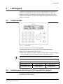
LCD keypad ...........................................................................................43
Technical data.........................................................................................43
Installing and addressing a LCD keypad to the system..........................43
LCD keypad Installation ..........................................................................44
Programming a LCD keypad – Local program mode .............................44
Accessing local program mode...............................................................45
Local program mode menu tree..............................................................45
Local program mode direct program addresses .....................................47
Exiting local edit program mode..............................................................47
5
Building Technologies
Fire Safety & Security Products
6
Building Technologies
Fire Safety & Security Products
8.4
8.4.1
8.4.2
8.4.3
8.5
8.5.1
8.5.2
8.5.3
8.5.4
8.5.5
8.5.6
8.5.7
8.5.8
8.5.9
8.6
8.6.1
8.6.2
8.6.3
8.6.4
8.6.5
8.6.6
8.6.7
8.6.8
8.7
8.7.1
8.7.2
8.7.3
Programming a keypad to the system – addressing...............................47
Language change of LCD .......................................................................48
LCD keypad address assignment ...........................................................49
Copying text to another LCD keypad ......................................................49
Changing names – personalization of the system ..................................49
How to use the alphanumeric keypad buttons ........................................50
Changing the keypad name ....................................................................51
Changing the user names .......................................................................51
Changing the zone names ......................................................................51
Changing the keypad area name............................................................52
Changing the output names ....................................................................52
Changing the area single character identifier .........................................52
Resetting individual text to default or last saved setting .........................53
Resetting all text to default......................................................................53
Operating a LCD keypad.........................................................................53
LCD keypad view memory mode ............................................................53
Current system alarms ............................................................................53
Historical memory event..........................................................................54
LCD quick view mode .............................................................................54
Arming or disarming two areas at a keypad............................................55
Toggle chime mode on-off ......................................................................55
Send manual test call..............................................................................55
Manual answer an incoming call .............................................................55
System settings of the LCD keypad........................................................56
LCD backlight adjustment .......................................................................56
Keypad button backlight adjustment .......................................................56
Volume adjustment of the keypad buzzer...............................................56
9
9.1
9.2
9.3
9.4
9.4.1
9.4.2
9.4.3
9.4.4
9.4.5
9.4.6
9.4.7
9.4.8
9.4.9
9.4.10
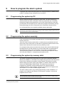
How to program the alarm system ......................................................57
Programming the system by PC .............................................................57
Programming the system remotely .........................................................57
Programming the system by memory stick .............................................57
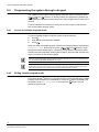
Programming the system through a keypad ...........................................58
Access to installer program mode...........................................................58
Exiting installer program mode................................................................58
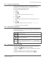
Keypad code programming .....................................................................59
Keypad menu programming....................................................................59
Selecting the main-menu headings.........................................................59
Selecting the sub-menu headings...........................................................60
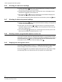
Selecting the data entry-menu headings ................................................60
Showing numeric programmable options in clear text ............................60
Stepping back through the menus ..........................................................60
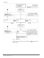
Flowchart for button function on the keypad ...........................................61
10
10.1
10.2
10.3
Default access codes............................................................................62
Access code to the user mode - default user PIN...................................62
Access code to the installer mode - default installer PIN........................62
Reset a system to default settings ..........................................................62
11
11.1
11.1.1
11.1.2
11.2
11.3
11.4
11.5
11.6
11.7
11.8
11.9
11.10
11.11
11.12
11.13
Programming users ..............................................................................63
User codes ..............................................................................................63
Adding or changing a user code .............................................................63
Removing a user code ............................................................................63
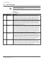
User code type ........................................................................................64
User access options................................................................................65
User code privileges ...............................................................................66
Radio user type .......................................................................................67
Radio user privileges ..............................................................................67
User time zone assignments...................................................................68
User to keypad assignment (user devices).............................................69
Radio pendant panic beeps to keypad ...................................................69
User to output mask................................................................................70
User can turn an output on .....................................................................70
User can turn an output off .....................................................................71
Radio pendant panic alarm to output ......................................................71
12
12.1
12.2
12.3
12.4
12.5
12.6
Learn, find and delete remote controls and tags...............................72
Learn a remote control / radio pendant...................................................72
Delete a remote control / radio pendant .................................................72
Find a remote control / radio pendant location .......................................73
Learn an access tag / card code to the system ......................................73
Delete an access tag / card code............................................................74
Find an access tag / card location ..........................................................74
13
13.1
13.2
13.3
13.4
13.5
13.6
13.7
13.8
13.9
Miscellaneous panel and timing settings...........................................75
Installer code...........................................................................................75
Duress digit .............................................................................................75
Dial report delay ......................................................................................75
Radio zone supervised timer ..................................................................76
Two trigger timer .....................................................................................76
Mains fail reporting delay ........................................................................76
Receiver fail delay-timer .........................................................................77
Upload-Download site code number.......................................................77
Temporary output disable .......................................................................77
14
14.1
14.2
14.3
14.4
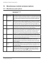
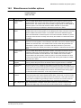
Miscellaneous installer and panel options.........................................78
Miscellaneous panel options...................................................................78
Miscellaneous installer options ...............................................................79
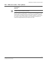
Miscellaneous user options.....................................................................80
Hide user codes – User options..............................................................81
15
15.1
15.2
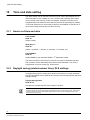
Time and date setting ...........................................................................82
How to set time and date ........................................................................82
Daylight saving (winter/summer time), DLS settings ..............................82
16
16.1
16.2
16.3
16.4
16.5
Outputs ..................................................................................................84
Output options.........................................................................................84
Output on delay, pulse, reset and chime times.......................................86
Output voice board remote control start message..................................87
Un-map an output ...................................................................................87
Assigning a time zone to an output.........................................................88
7
Building Technologies
Fire Safety & Security Products
8
Building Technologies
Fire Safety & Security Products
17
17.1
17.2
17.3
17.4
17.5
17.6
17.7
17.8
17.9
Areas ......................................................................................................89
Area arm and special function options....................................................89
Area arm-stay pulse and chirps to output ...............................................91
Area arm-stay beeps keypad ..................................................................93
Exit delay time settings / area .................................................................94
Monitoring account code number............................................................94
Remote arm/disarm DTMF code and start voice message ....................95
Area exit beeps to output ........................................................................95
Area delinquency delay – arming activation indication ...........................96
Automatic arm/disarm time zone ............................................................96
18
18.1
18.2
18.3
18.4
18.5
18.6
18.7
18.8
18.9
18.10
18.11
18.12
18.13
Keypads .................................................................................................97
Keypad area assignment ........................................................................97
Keypad button individual operations (beeps and LED control)...............97
Keypad system beeps and LED options .................................................98
Keypad <Arm> Button options ................................................................99
Keypad <Stay> button options ..............................................................100
Keypad <A> button options...................................................................101
Keypad <B> button options...................................................................102
Keypad to output mask .........................................................................103
Control button to output mask ...............................................................103
Keyboard panic, fire and medical alarms to outputs and KP buzzer ....103
Keypad wrong code and manipulation alarms to outputs .....................104
Keypad chime timer ..............................................................................105
Learn a card reader to the system, addressing an LED .......................106
19
19.1
19.2
19.3
Key-switches .......................................................................................107
Key-switch wiring ..................................................................................107
Key-switch area assignment .................................................................107
Key-switch arm-disarm options .............................................................108
20
20.1
20.2
20.3
20.4
20.5
20.6
20.7
20.8
20.9
20.9.1
20.9.2
20.10
20.11
20.12
20.13
20.14
Zones....................................................................................................109
Zone area assignment ..........................................................................109
Zone type options- basic information ....................................................109
Special zone type options .....................................................................112
Different End of Line (EOL) Resistor value options ..............................113
Vibration sensor zone type - zone response time.................................114
Supervising setting of wireless detector type........................................115
Zone alarms to output mapping ............................................................116
Zone alarms to keyboard buzzer mapping............................................117
Zone timing settings ..............................................................................118
Entry delay time ....................................................................................118
Retrigger time........................................................................................119
Armed and stay mode entry delay times to output mapping.................119
Zone movement / activity control – watch timer....................................119
Learn a wireless detector / code to the system.....................................120
Delete a wireless detector / code of the system ...................................120
Find a wireless detector / code in the system .......................................120
21
21.1
21.2
21.3
Time zones...........................................................................................121
Holidays.................................................................................................121
Time zone days.....................................................................................121
Time zone start and stop times .............................................................122
22
22.1
22.2
22.3
22.4
22.5
22.6
22.7
22.8
Dialer ....................................................................................................123
Dialer options ........................................................................................123
Auto answer ring count .........................................................................125
Test call options ....................................................................................125
Listen dialing function through keypad and output ...............................126
Dialing pre-fix numbers .........................................................................127
Remote control by external phone through DTMF dialing tones ..........127
Forced test call code options ................................................................128
Manual test call initiated voice message number .................................128
23
23.1
23.2
23.3
23.4
23.5
23.6
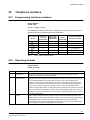
Telephone numbers ............................................................................129
Programming telephone numbers.........................................................129
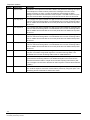
Reporting formats..................................................................................129
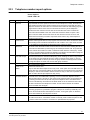
Telephone number report options.........................................................131
Maximum dial re-tries per telephone number .......................................132
Dial progress options ............................................................................132
Call divert numbers and options ...........................................................135
24
24.1
24.2
4 plus 2 program options ...................................................................137
Using the 4 plus 2 codes.......................................................................137
Mains-Battery-Tamper-Duress and arming 4 plus 2 codes ..................138
25
25.1
25.2
SIA Codes reporting format SIA III ....................................................139
SIA reporting codes - standard default setting......................................139
Individual SIA reporting codes ..............................................................140
26
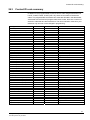
26.1
26.2
26.3
Contact ID code summary..................................................................141
Change Zone Contact Identification (CID) report codes.......................141
Change keypad panic, fire and medical alarms CID report code .........142
Contact ID code summary ....................................................................143
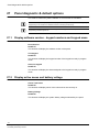
27
27.1
27.2
27.3
27.4
27.5
27.6
27.7
27.8
Panel diagnostic & default options ...................................................144
Display software version - keypad numbers and keypad areas ...........144
Display active zones and battery voltage .............................................144
Walk test mode – transmission test – installation help .........................145
Read or write to/from the memory stick (EEPROM) .............................146
Reset back to defaults ..........................................................................146
Start a call-back call..............................................................................147
Installer code.........................................................................................147
Radio Signal Strength Indication (RSSI)...............................................147
28
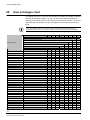
User privileges chart ..........................................................................148
29
Telecom interface connection ...........................................................150
9
Building Technologies
Fire Safety & Security Products
10
Building Technologies
Fire Safety & Security Products
30
30.1
30.2
30.3
30.4
30.5
30.6
30.7
30.8
30.9
30.10
30.11
30.12
30.13
30.14
30.15
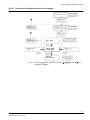
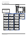
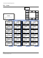
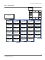
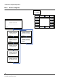
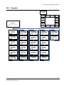
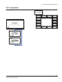
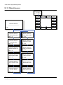
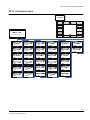
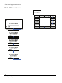
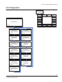
Flow chart of programming menus...................................................151
Installer menu........................................................................................151
Installer: Users ......................................................................................152
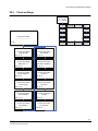
Clock settings ........................................................................................153
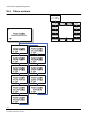
Phone numbers.....................................................................................154
Dialer .....................................................................................................155
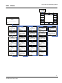
Areas .....................................................................................................156
Zones main............................................................................................157
Zones outputs .......................................................................................158
Keypads ................................................................................................159
Outputs..................................................................................................160
Keyswitch ..............................................................................................161
Miscellaneous .......................................................................................162
4+2 event codes....................................................................................163
SIA event codes ....................................................................................164
Diagnostics............................................................................................165
31
31.1
31.2
31.2.1
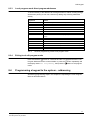
Support.................................................................................................166
FAQ frequently asked questions ...........................................................166
Typical programming guidelines ...........................................................167
DTMF command control how to use and program ...............................167
11
Building Technologies
Fire Safety & Security Products
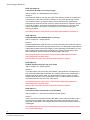
Terminology
1
Terminology
12
Building Technologies
Fire Safety & Security Products
Display text
Other term
Arm
Dialer
Dual trigger
Handover
Set
Communicator
Double knock
Entry Route
Installer
Open
Pendant
Stay
Unstay
Engineer
Unset
Remote Control
Part-Set
Unset Part-Set
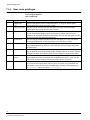
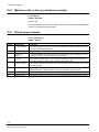
New features and changes as of version 9.07
2
New features and changes as of version 9.07
2.1
New features
All the features that are new as of version 9 07 are listed below.
z P25E 3E: Dial Report delay
refer to chapter 13.3: Dial report delay
z P25E 13E Option 6: Allow monitored Keypad Bus Output Board
refer to chapter 14.3: Miscellaneous user options
z P25E 13E Option 8: Limited Events & Dialer to 3 of any one type
refer to chapter 14.3: Miscellaneous user options
z P36E Option 5: Output disabled when P25E 3E timer is running
refer to chapter 16.1: Output options
z P37E Option 4: Disable outputs during two way voice mode
refer to chapter 16.1: Output options
z P46E Option 7: Cannot Arm if Zone unsealed at end of Exit Delay
refer to chapter 17.1: Area arm and special function options
z P122E Option 3: Not on Exit Delay Time
refer to chapter 20.2: Zone type options- basic information
z P175E 2E Option 8: Allow the panel to auto-answer after 1 ring if set up to do fill
duplex two way voice
refer to chapter 22.1: Dialer options
z P183E Option 5: Allow for direct on-line two way voice following reporting of an
alarm event
refer to chapter 23.3: Telephone number report options
z P200E Option 13: Installer code
refer to chapter 27.7: Installer code
z P200E Option 14: RSSI
refer to chapter 27.8: Radio Signal Strength Indication
2.2
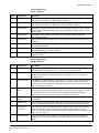
Changes
Walk test now exits back to program mode if you will press on
for exit.
On previous version when you pressed on
to terminate walk test the panel was
get out from program mode. Now when you press
to terminate walk test the
panel stay on program mode.
When Learning Radio device not found now shows Not Found! instead of
non-descriptive Done (for zone and pendant).
When entering to learning mode and no device was found, the panel will present
the message Not Found! (Instead of the message Done on the previous
version).
13
Building Technologies
Fire Safety & Security Products
New features and changes as of version 9.07
Learning Radio device (zone and pendant) now shows Code in-use! on
second line if device already known, learn process will continues.
When attempting to learn an already learned device, the panel will present the
message Code in- use! and will continue with the learning process (valid for
wireless detectors and pendant).
Keypad goes to power-save after 10 seconds, extinguishing all led backlights
and indicators except 'Trouble' (linked to option P73E option 7.)
To keep on power save the keypad backlights will turn off if no operation was made
after 10 second.
If you have more then 1 keypad, only the keypad that you work with will turn on his
backlights.
This function was linked to address P73E option 7 (if on the backlights turn off after
10 second).
The trouble LED will always operate in all keypads in case of system trouble.
Trying to arm from Keypad with open zone and arm refuses, keypad will
show broken zones as-if the enter key was pressed.
If you have an open zone while you arm the panel, the keypad will present the
open zone number (e.g. 02 for zone 2). If you press on
twice the name of the
zone will also be presented.
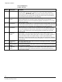
Showing broken zone list will show zones by name-text after numeric list by
pressing enter key again.
In normal mode – standby the display shows System OK even with an open zone.
If
is pressed, it indicates all open zones by number 01 03 08 etc.
By pressing enter again each zone will be shown by his name (text).
When arming the system it's indicate open zones with numbers and pressing on
enter will show zone name text for all zones (press
for moved from one zone to
another).
"Test message sent" will not longer be send if the dialer is not Activated
(P175E 1E 1 = off).
If you disable the dialer activation on P175E 1E option 1 (off), the message "Test
message sent" will no longer be shown on memory log.
Extended initial listen from 2 minutes (1.5+30s warn) to 3 minutes (2.5+30s
warn).
After establish 2 way voice conversation, a vocal sound will start after 2.5 minutes
(instead of 1.5 minutes on previous version) if no manual kiss off was entered.
Disabled beep patterns to keypad if voice monitor is on. If 2 way voice is on
the keypad beeps will stop.
In case of 2 way voice conversation after alarm, all external sounds like keypad
beeps and siren (needed to be programmed in advance) will stops. Once the 2 way
voice is off only the siren (outputs) will start again.
Installer cannot longer enter to P200E 13E (installer mode).
P200E 13E was letting installer mode enter installer code again to bypass any
alarm that request from the installer to enter first through user code (requirement
for user) - now ignores if installer enters code.
14
Building Technologies
Fire Safety & Security Products
Programming to EN 50131
3
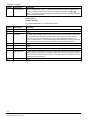
Programming to EN 50131
Necessary programming to EN 50131 installations
The control panel Sintony 60 offers a lot of different features. If the installation must
be according to EN 50131 some of the features and options for users must be
restricted.
To be according EN 50131 requirements the following functions / features must be
programmed as described:
Mute siren
refer to chapter 6.4: Mute siren
This option must be programmed to mute all acoustic devices automatically during
listen-in with the full duplex two way voice board.
According EN 50131-3 if an alarm occurred during Exit Delay the dialer
should reported only after 30sec.
And the Siren shouldn't activate until the Exit delay is expired.
P25E 3E:
Dial Report delay (0-255 Seconds)
refer to chapter 13.3: Dial report delay
If this address is set to 0, there will be no report delay. If it is set to any value other
than 0 then a delay equal to the programmed value will stop the panel from
reporting an instant zone alarm via the dialer until this delay time expires (both
during the exit delay time if option 3 is on at P122E for a zone or when an instant
zone is triggered when fully armed). While the timer is active certain outputs can be
disabled at location P36E option 5. Once the timer has expired it will not start
again, the panel must be disarmed then armed to reset the timer.
According EN 50131-3 if an alarm occurred during Exit Delay the dialer
should reported only after 30sec.
P25E 13E Option 6:
Allow Monitored KP Bus Output Board
refer to chapter 14.3: Miscellaneous user options
Option 6:
Monitored Keypad Bus Output Board: this option performs a similar function to
option 6 at location P25E 10E in that if it is turned on the output status messages
are sent to the keypad bus. The difference with this option is when turned on the
panel is expecting the OUTPUTX4 board connected to the keypad bus to
acknowledge the messages. If the OUTPUTX4 does not acknowledge the output
status messages the panel will show an output board failure. This option should
only be turned on if an OUTPUTX4 board with the latest software is connected to
the keypad bus.
According EN 50131-3 all units connected to the Control Panel should be
monitored.
15
Building Technologies
Fire Safety & Security Products
Programming to EN 50131
P25E 13E Option 8:
Limit Events & Dialer to 3 of any one type
refer to chapter 14.3: Miscellaneous user options
Option 8:
Limit Events & Dialer to 3 of any one Type: if this option is turned on the panel will
not record any more than 3 events in memory for any event type during a single
arm or disarm cycle, e.g. if the AC failed 4 times while armed or disarmed the
panel will only record the AC fail 3 times in memory and will only report the AC fail
3 times to the dialer. As soon as the arm state has changed any count are reset
back to zero again. If this option is off there is no limit on the recording and
reporting of events.
According EN 50131-3 the events of the same type should be limited to 3.
P36E Option 5:
Output Disabled when P25E3E timer is running
refer to chapter 16.1: Output options
Option 5:
Output Disabled when P25E 3E timer is running: this option will cause the output to
be disabled when the dialer reporting delay is active. It is designed to keep external
audible alarms silent when the dial delay is active (allowing internal alarms to warn
that the alarm will be reported to monitoring if not unset) but if the alarm hasn’t
been reset before the timer expires the external alarm will sound.
According EN 50131-3 if an alarm occurred during Exit Delay the dialer
should reported only after 30sec.
And the Siren shouldn't activate until the Exit delay is expired.
P37E Option 4:
Disable outputs during two way voice mode
refer to chapter 16.1: Output options
Option 4:
Turn Output OFF during Two Way Voice Mode: if the panel has a full duplex two
way voice board fitted and the settings at P175E 2E option 8 and P183E option 5
are set to allow full duplex mode, any outputs with this option turned on will be
disabled while two way voice is operational. This is to ensure that local sirens do
not interfere with the two way voice audio signal.
According EN 50131-3 if an alarm occurred during Exit Delay the dialer
should reported only after 30sec.
And the Siren shouldn't activate until the Exit delay is expired.
P46E Option 7:
Cannot Arm if Zone unsealed at end of Exit Delay
refer to chapter 17.1: Area arm and special function options
Option 7:
Cannot Arm if Zone unsealed at end of Exit Delay: if this option is turned on and a
zone becomes unsealed as the exit delay expires the panel will fail to arm and
report this via the dialer. The unsealed zone must be corrected and the system rearmed again.
According EN 50131-3 the system shouldn't Arm if one of the zones is open
at the end of Exit Delay.
16
Building Technologies
Fire Safety & Security Products
Programming to EN 50131
P122E Option 3:
Not an Exit Delay Zone
refer to chapter 20.2: Zone type options- basic information
Option 3:
Not an Exit Delay Zone: if this option is turned on the zone will not have any exit
delay and will cause an instant alarm if triggered during the exit delay time. Also
you MUST ensure that if this option is turned on for a zone, that same zone should
not have any entry delay (P144E) programmed. If the zone does have an entry
delay the zone can activate during the exit time thereby starting an entry delay on
the same zone which means the user might not be aware of the pending alarm and
leave the premises. If the zone has no entry delay and the zone is triggered during
the exit time the alarm will then be instant alerting the user that they deviated off
the exit route.
According EN 50131-3 the user must have an option to define the zones in
the exit route.
P200E Option 13:
Installer code
refer to chapter 27.7: Installer code
Installer Code: if option 2 in P25E 10E (Installer Direct Access) is off, the only way
for installer to access is through client mode. The installer must enter first to client
mode and go to P200E 13E and enter the code there. The code will not be
presented on the LCD (confidential), he will be blanked out.
According EN 50131-3 the system shouldn't present the Installer code while
typing it through the client mode.
17
Building Technologies
Fire Safety & Security Products
System overview
4
System overview
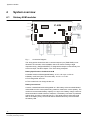
4.1
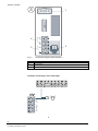
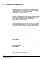
Sintony 60M modular
In
PHONE LINE IN
IC-60M
Lin
AC_IN
TELECOM
PHONE LINE IN
Out
PHONE LINE OUT
Red
Lin
Black
Dat
C NC N
Relay/OUT4
BUS CONNECTION
FOR EXTERNAL
KEYPAD AND OTHER
ACCESSORIES
Clk
Neg
Pos
12V
Gnd 12V
1
2
3
Outputs
4
Gnd 12V
1
C
2
3
C
4
5
C
6
7
C
8
Tmp Gnd 12V
COM
GND
Gnd
In factory settings the
jumper is set between
COM & GND.
The com contact can be
connected to 12V by
setting the jumper.
With out the jumper the
relay contacts are floating.
OUTPUTS
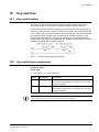
Fig. 1
INPUTS Z1...Z16
POWER FOR
DETECTORS &
ACCESORIES
Connection Diagram
The wiring option shown here with a common tamper input (TAMP/GND) is not
allowed in all countries, if the installation has to be done according to legal
requirements (e.g. Belgium/INCERT).To integrate the tamper contact directly into
each zone input, see also chapter 4.3.2: Zone wiring examples.
Battery Specifications for Model IC60 M
z Sealed Lead-Acid Rechargeable Battery 12 V/1.3 Ah up to 12 V/7 Ah
z Battery cutoff level (when AC mains fails): 10.3 V ± 0.1 V DC.
z Full charge after 48 hours.
z The current limit over charge is 600 mA.
Battery Connections
Connect a sealed lead acid rechargeable 12 V DC battery to the terminals labeled
red and black on the control panel being careful to observe the correct polarity. The
maximum recommended battery capacity is 7 amp hours. Battery charge current at
these terminals is limited to 600 mA maximum. The battery connection is protected
against short circuits by a thermal fuse (F1). The panel performs a dynamic load
test on the battery every 15 seconds and if it fails the test at any time it will flash
the battery LED.
18
Building Technologies
Fire Safety & Security Products
System overview
General Specifications:
z The range of the 12 V uut which is used for feeding sensors is between 10.2 to
14 V DC (working on mains or standby battery).Ripple is up to 0.1 V p.p.
z Each voltage out 12 V protected by reset able fuse of 500 mA.
z The max total current allowed to draw during alarm is 1 A.
z Self current consumption (IC60M+IKP6) from battery is: 100 mA.
z Operating temperature: 0-50º C
z Max. current consumption from the mains less than 150 mA.
z The panel is equipped with a type A power supply according EN 50131-6
To meet the EN 50131 and the T014 (Belgium) to withstand battery life not less of 12 hours please
note that the maximum current for accessories in standby mode should be less then 300 mA
AC Connections:
Connect the mains wires Phase (~) and Neutral (N) to the Mains terminal inside the
IC60M housing and secure the cable with the provided cable clamp
The AC Input is protected by fuse:
Fuse (TD-Time Delay) T250 mA/250 V, 5x20 mm Glass.
AC level 230 V, 50 Hz ±10%.
Notifications:
z Alarm transmission classification ATS 2
z According EN 50131-1 notification option A applies. This means that an external
warning device needs to be connected.
This panel is designed in accordance with:
z EN 50131-1
z TS 50131-3
z EN 50130-4
z EN 50130-5
z EN 50131-6
z EN 50131-5-3
z EN 50136-1-1
z EN 50136-2-1
19
Building Technologies
Fire Safety & Security Products
System overview
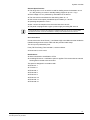
4.2
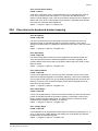
Sintony 60 compact
Fig. 2
Connection Diagram IC60 compact overview
1
2
3
C NC NA
OUTPUTS OUT 4
+ C _
20
Building Technologies
Fire Safety & Security Products
3
Dat Clk NEG POS
+
BAT
5
Lin
_
Fig. 3
2
4
7
6
1
KBD
Connection Diagram IC60 compact 1
1
Normally closed/normally open.
In factory settings the jumper is set between COM & GND □■■ (0V).
The com contact can be connected to 12V by setting the jumper ■■□ (+12V connected).
Without the jumper the relay contacts are floating (potential free).
2
Out 4 - Relay
3
Outputs Open Collector
4
Outputs Keypad Selector: Horizontal □■■ Vertical ■■□
5
Bus connection for external Keypads and other accessories.
6
Battery IN
7
LCD pin header for Vertical configuration.
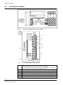
System overview
2
6
2
1
+ C _
0V 12V Z1
C
Z2 Z3
C
Z4
C
0V 12V
Z5
C
Z6 Z7
C
Z8 TAMP
3
4
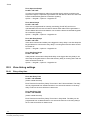
Fig. 4
Connection Diagram IC60 compact 2
Power for detectors & accessories
2
Jumper for bypass the tamper of the control panel in Line. Tamper of keypad, GSM etc. will still
be reported.
Front and back
tamper is
working.
□■■
■■□
EOL is bypassed
All tampers in control panel are
bypassed- requires no resistor
EOL and front and back tamper
of housing is bypassed (only for
installation!) new from V9.07 on.
□□□
1
No jumper connected front
and back tamper is working.
EOL resitors are requested in
the installation of the zone
(new from version 9.07 on).
3
INPUTS Z1…Z16
4
Power for detectors & accessories
5
Connector for internal siren (could be disconnected during installation) > 100dB
6
LCD pin header for Horizontal configuration
21
Building Technologies
Fire Safety & Security Products
System overview
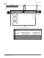
3
1
OUT LINE IN
4
3
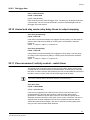
Fig. 5
2
Connection Diagram IC60 compact 3
1
Programming Port
2
RJ11-Line IN
3
Phone Line IN
4
Phone Line OUT
Example: Connecting a siren, flash light…
0V 12V Z1
C
Z2 Z3
O
2
3
C NC
OUTPUTS OUT 4
+ C _
22
Building Technologies
Fire Safety & Security Products
...
...
C
Z4
C
System overview
Example: Interface connection to open collector
0V 12V Z1
C
Z2 Z3
C
Z4
C
...
2
3
C NC NO
OUTPUTS OUT 4
+ C _
...
Battery Specifications for Sintony 60 compact
z Ni-MH Rechargeable Battery 12V/1.8Ah.
z Battery cutoff level (when AC mains fail): 10.5 ±0.1V.
z Full charge after 48 hours.
z The current limit over charge is 260 mA.
Battery Connections
Place the battery in its location, and secure it with the rubber band (refer to Fig. 6).
Connect the battery plug into its connector (refer to Fig. 3).
General Specifications:
z The range of the 12 V Out which is used for feeding sensors is between 10.2 to
14.3 V DC (working on mains or standby battery) .Ripple up to 0.1V p.p.
z Each voltage out 12 V protected by reset able fuse of 500 mA.
z The max total current allowed to draw during Alarm is 0.8 A.
z Self current consumption from battery is : 60 mA
z Operating temperature: 0-50º C
z Max. current consumption from the mains less than 150 mA.
z The panel is equipped with a type A power supply according EN 50131-6
z AC mains input 100 V AC – 240 V AC, 50/60 Hz
z The build in sounder has a value of > 100dB
z The main fuse AC = T250 mA, 250 V glass
To meet the EN 50131 and the T014 (Belgium) to withstand battery life not less of 12 hours please
note that the maximum current for accessories in standby mode should be less then 65 mA.
23
Building Technologies
Fire Safety & Security Products
System overview
Fig. 6
Placing the rubber band and fixing the Battery
Sintony 60 compact AC Connection
The electronic board is fit into the housing and it’s equipped with AC/DC adapter.
In countries or installations where the internal build in adapter should not be used,
the panel could be fed from an external adaptor (100-240 V AC/14.4 V DC, 1 A).
(Special wiring required ask your local country agent).
The mains input cable has to be secured with a special cable clamp as per the
following drawing:
Fig. 7
AC cable fixing Sintony 60 compact
Fig. 8
AC connection port Sintony 60 compact
The main fuse AC = T250 mA 250 V glass
If the unit is not connected to ground, malfunction may occur, especially when the voice board is
connected.
24
Building Technologies
Fire Safety & Security Products
System overview
Notifications:
This panel is designed in accordance with:
z EN 50131-1
z TS 50131-3
z EN 50130-4
z EN 50130-5
z EN 50131-6
z EN 50131-5-3
z EN 50136-1-1
z EN 50136-2-1
4.3
Zone connections
To install hardwired detectors to the control panel see the following wiring options.
If you want to connect wireless radio detectors to the control panel, now wiring is
needed (see chapter 20.12, 20.13, 20.14: Learn, Delete and Find a wireless
detector / code in the system; P164, 165, 166E).
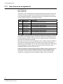
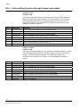
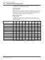
4.3.1
Zone input configurations hardwired
The Sintony 60 has nine separate programmable monitored analogue inputs:
z 8 x programmable, multi-state detection inputs
z 1 x programmable tamper input (with optional Key-switch functions)
To differentiate between various signals (alarm, tamper, detector address) over the
same cable, the Sintony 60 is equipped with a resistance measurement on each
input. To monitor the cabling and the installed peripherals continuously (also
against sabotage during the control panel is not armed) each Input should contain
at least one of the described resistor, so called EOL – end of line values.
The following different resistors, which are delivered with the control panel, are
used as a standard.
Zone address EOL- end of line Resistors
This resistor value should be built in the detector to monitor the zone input of this
particular detector.
Zones 1-8 (which are also called low zones)
4k7Ω (yellow, violet, red) for detectors in the zone 1-8
Zones 9-16 (which are also called high zones)
are realized with zone doubling, means the terminal block 1-8 are used but with
different resistor value.
8k2Ω (grey, red, red) for detectors in the zone 9-16 (high zone)
Tamper address EOL- end of line Resistors
This resistor value is used to monitor if somebody tries to manipulate the
installations (opening housings, cutting cables etc.). It should be installed in the
detector.
25
Building Technologies
Fire Safety & Security Products
System overview
2k2Ω (Red, Red, Red) for tamper
To overtake existing installation with already build in different resistor values, the Sintony 60 could
also be programmed to different values (see chapter 20.4: Different End of Line (EOL) Resistor value
options; P125E).
If an iInput is programmed as a wireless input, the system will ignore all hardwired connection to this
input and look only for the radio signal! (see chapter 20.2: Zone type options- basic information; Zone
A Options, option 5; P122E)
4.3.2
Zone wiring examples
The connection of each device depends on the type of switch which is used in the
detectors. We differentiate between:
z N/C normally closed, requires serial connection
z N/O normally open, requires parallel connection
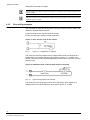
Option 1: Only one EOL- end of line resistor
Fig. 9
Type 1-11 - Single EOL no Tamper
The zone input must be programmed as single resistor value (see chapter 20.4:
Different End of Line (EOL) Resistor value options; options 1-11; P125E). The
tamper contact should be monitored separately with the same connection schema
(tamper input).
Option 2: Installation with 1-8 Zones with Tamper monitoring
Fig. 10
Type 12 Single Zone with Tamper
The Zone input must be programmed as zone with tamper (see chapter 20.4:
Different End of Line (EOL) Resistor value options; option 12; P125E).
26
Building Technologies
Fire Safety & Security Products
System overview
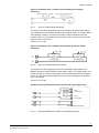
Option 3: Installation with 1-16 Zones (zone doubling) with Tamper
monitoring
Fig. 11
Type 14 Zone doubling with tamper
The zone input must be programmed as zone doubling with tamper (see chapter
20.4: Different End of Line (EOL) Resistor value options; option 14; P125E). When
zone doubling is used (1-16 zones) the system counts automatically the zone
numbers from 9-16. This means terminal block Z1 and C on the control panel are
inputs for zone 1 and zone 9.
Z2=Z10, Z3= Z11 etc.
Option 4: Installation with 1-16 Zones (zone doubling) without Tamper
monitoring
Fig. 12
Type 15 zone doubling without tamper
The zone input must be programmed as zone with tamper (see chapter 20.4:
Different End of Line (EOL) Resistor value options; option 15; P125E). When zone
doubling is used (1-16 zones) the system counts automatically the zone numbers
from 9-16. This means terminal block Z1 and C on the control panel are inputs for
zone 1 and zone 9.
Z2=Z10, Z3= Z11 etc.
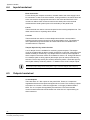
Example of wiring a PIR Detector (N/C) for Alarm & Tamper Monitoring
4K7
Z
C
2K2
Alarm
Contact (N/C)
Tamper
Contact (N/C)
12V
+
0V
(GND)
-
Fig. 13
PIR Internal Connections
Wiring a PIR Detector for Alarm and Tamper Monitoring
27
Building Technologies
Fire Safety & Security Products
System overview
4.4
Inputs hardwired
Earth Connection
For the Sintony 60 compact connection, the earth lead of the mains supply has to
be connected. In case of the IC60 modular, if using metal box, the mains earth has
to be connected to the appropriate terminal on the mains terminal block in the
control box cabinet. Also connect a lead from this earth point to the terminal
marked with the earth symbol (next to AC terminals) on the panel PCB.
Line In
These terminals are used to connect the panel to the incoming telephone line. The
dialer uses this line for reporting alarm events.
Line Out
These terminals are used to connect telephones and other communication
equipment to the incoming phone line via the panel dialer circuit. The telephone
line is passed through the controller to ensure that the line is available to the
controller when it is required.
Tamper/ Input for Key switch function
A 24 hr tamper circuit is available for monitoring system tampers. This tamper
circuit is programmable as either normally closed loop or 2k2 EOL supervision (the
default is usually a closed loop). Any tamper alarms on this input are mapped to
alarm outputs in the same manner as for detection zones 1-16. Using Dual-End-ofLine resistors (refer to wiring options) the tamper input can also provide two keyswitches. The low key-switch (4k7 resistor) will be key-switch 1 while the high keyswitch (8k2 resistor) will be key-switch 2. In addition to the zone & tamper inputs.
Zone tamper jumper setting must be active (refer to. Fig. 4 Connection Diagram IC60 compact 2)
4.5
Outputs hardwired
12 Volt Outputs
There are three 12 V DC outputs on the panel PCB. These 12 V outputs are
regulated and thermal fuse protected against short circuits. The accessory outputs
are marked 12 V and 0 V, while the keypad bus 12 V supply is labeled POS &
NEG. The 12 V outputs are supplied by thermal fuses. The recommended
maximum total load that should be drawn from all of the 12 V outputs during an
alarm is 800 mA.
28
Building Technologies
Fire Safety & Security Products
System overview
Outputs 1 & 2
Fully programmable, high current, open drain (high-going-low) type FET outputs
capable of switching up to 1 A @ 12 V DC. These 2 outputs are normally set as
switched outputs, providing power for 12 V sirens. If required, these outputs can be
programmed to be siren outputs designed to drive an 8 ohm 10 watt horn speaker
on each output (refer to chapter 16.1: Output options; Output D options, option 1;
P37E). Also if a horn speaker is connected to output #1 you may select (refer to
chapter 22.4: Listen dialing function through keypad and output; Output 1 Listen In;
P175E 7E) as the listen-dialing feature, to listen to the dialing sequence which than
could be heard at the speaker.
In IC60 compact unit the output 1 is assigned to operate the build in internal siren.
Output 3
This is a low current, open drain (high-going-low) type FET outputs capable of
switching up to 500 mA. Like outputs 1 & 2 it is fully programmable.
Connecting devices which draw current in excess of 500 mA to output 3/can
damage the output.
Output 4-Relay Out
Output 4 is a relay output with single pole changeover contacts. If required, the
Common (C) contact of the relay is connected by default to GND via JUMPER, the
jumper can be selected to 12 V or removed.
4.6
System Bus connection - keypad port
The terminals marked POS, NEG, CLOCK, & DATA make up the communications
port which the keypads and other intelligent bus devices use to communicate with
the Sintony 60. The terminals are connected to corresponding terminals on the
remote devices. The LIN terminal is only used by the keypads and utilizes a fifth
wire to provide a communicator listen-dialing facility (a dialing ton could be heard
through the buzzer). This feature is particularly useful when servicing monitoring
faults. The 12 V power supply (POS, NEG) of the bus is protected by a separate
thermal fuse.
4.7
Programming port
With the separate available programming cable IAQ6-1 and the programming
software Sylcom 60 IAS6-1 the Sintony 60 could be connected via this port directly
to a PC. All system parameters or settings could be easily changed with this
program. Furthermore this port could also be used to connect the memory stick
IMM6-10 to up or download the default setting of an alarm system. This speeds up
the process of programming, especially if similar settings have to be used with
different installations.
If the control panel is connected to the telephone line, the same software could be used to program/
monitor the control panel through the telephone line remotely, if the PC is equipped with a telephone
modem.
29
Building Technologies
Fire Safety & Security Products
Contact less card reader IAR6-30 for keypad bus connection
5
Contact less card reader IAR6-30 for keypad bus
connection
The IAR6-30 contact less reader is used as a proximity access card reader with a
full numeric keypad for additional PIN functionality and standard tags or cards
which operates in the 125 kHz band. Its functionality is identical to a keypad and
therefore it is programmed into the system as a standard keypad.
In total maximum 8 keypads/card readers can be connected to a Sintony 60 control panel (Sintony 60
compact has one build in already- e.g. 7 more).
Under the following limitations:
Bus connections- max. length*
Up to 25 meter, 22AWG,
wire diameter 0.6mm
7 Keypads IKP6-03 or
Reader IAR6-30
8 Keypads IKP6-03 or
Reader IAR6-30
Up to 100 meter, 20AWG,
wire diameter 0.8mm
4 Keypads IKP6-03 or
Reader IAR6-30
4 Keypads IKP6-03 or
Reader IAR6-30
Each reader must have a unique keypad address number from 1-8 assigned so
that the various program options can be assigned (see chapter 18.13: Learn a card
reader to the system, addressing an LED; Reader Learn ;P99E).
The proximity readers flash out the assigned keypad address number on the LED whenever the panel
is in Installer Program Mode. This allows quick identification of the assigned address for each reader.
5.1
Additional arming functions
Depending on program options the reader IAR6-30 could also be used as an
arming/disarming device. If a user code or tag is presented to the reader it could
directly Arm/Disarm the alarm system. The reader can be set-up to operate on:
z a proximity tag or card only
z on entering of a valid user code only
z on presentation of the tag/card followed by the user code (PIN).
If the presented tag requires a PIN number to be entered, the LED on the reader
will flash for 5 seconds after a valid tag to indicate that the PIN number should now
be entered.
5.2
Panic functions
If the two button <Panic> ( ), <Fire> ( ) or <Medical> ( ) functions are
programmed to the keypad/reader (see chapter 18.2: Keypad button individual
operations (beeps and LED control); Keypad Options; options 5, 6 & 7; P72E)
these manual alarms can be generated at the reader by pressing
&
for
Panic,
&
for Fire and
&
for Medical alarms.
30
Building Technologies
Fire Safety & Security Products
Contact less card reader IAR6-30 for keypad bus connection
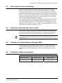
5.3
Zone input for door monitoring
There is an optional input to monitor an exterior gate to show if it is currently
opened or closed. This input is not EOL monitored and should only be used for
non-critical monitoring functions. A zone can be programmed to use this input for
its trigger (see chapter 20.2: Zone type options- basic information; Zone A Options,
option 4; P122E) so that the state of the input can be displayed on a keypad. This
allows saving cabling, because the zone is connected directly to the card reader /
bus and does not request separate zone cabling
The inputs are linked to the selected keypad address programmed into the reader.
For example if the reader being used was programmed as keypad # 1, then the
input can be assigned to zone 1 or 9 (see chapter 20.2: Zone type options- basic
information; Zone A Options, option 4; P122E), if the keypad address was # 2, the
input can then be assigned to zone 2 or 15, etc.
5.4
Output for electrical door lock control
There is also an output available on this reader that follows the same addressing
functionality as described in the zone input function. It can be used to activate an
electric lock as shown in the connection drawing. This helps to save cabling.
The reader output can only control the electrical lock! The Sintony 60 is not able to supply power for
an external lock. An additional external power supply is recommended depending on the type of door
lock which is used.
5.5
Indication of status/address through LEDs
If requested the LED on the reader can be linked to an output so that special
functions may be displayed at the reader if desired (e.g. chapter 18.13: Learn a
card reader to the system, addressing an LED; Proximity LED Follows Output;
P98E).
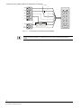
5.6
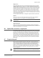
Proximity readers connections
Bus connections- max. length*
Up to 25 meter, 22AWG,
wire diameter 0.6mm
7 Keypads IKP6-03 or
Reader IAR6-30
8 Keypads IKP6-03 or
Reader IAR6-30
Up to 100 meter, 20AWG,
wire diameter 0.8mm
4 Keypads IKP6-03 or
Reader IAR6-30
4 Keypads IKP6-03 or
Reader IAR6-30
31
Building Technologies
Fire Safety & Security Products
Contact less card reader IAR6-30 for keypad bus connection
N/O Input
a
Pos
b
Neg
1
2
3
4
5
6
7
8
f
9
0
g
#
*
Clk
c
Dat
d
e
Lin
1N4004
+ 12 V
0V
(Gnd)
Fig. 14
+
Electric
Lock
_
h
Connection for Proximity and PIN Reader
When a card reader is connected to the system it must be restarted to address the reader. Is a keypad
already connected as address 1 the reader does not work correctly if addressed with the same
address.
32
Building Technologies
Fire Safety & Security Products
Voice board IAV6-90
6
Voice board IAV6-90
The voice board can only be integrated within the IC60 compact panel.
6.1
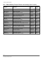
Product description
The voice board enables you to record multiple voice messages and then link them
to events so that a caller can get an audio status on different parts of the system
over the telephone. You can also call the control panel. Using the correct code
combinations you can to listen to any sound originating within protected premises,
thereby determining if an intruder is actually on the site or not. When the
microphone is activated, the sirens are muted in order to keep the background
noise as low as possible. This is a full duplex bi-directional voice channel enabling
you to talk to the intruder when the intruder is within a few meters of the control
panel. The intruder or visitor can then use the internal microphone to answer
questions you ask over the internal speaker.
Speech messages can be allocated to different alarm types and be used to give
status reports for command control.
Command control then enables you to arm or disarm the alarm system or to turn
specific outputs on or off using voice commands via a remote telephone call
(password protected).
z If the unit is not connected to ground, malfunction may occur (background noise, etc.).
z The quality of the voice messages depends on the quality of the telephone line.
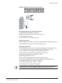
Features
z Voice message recording
z Total recording time: 90 seconds
z Message length should be min. 2 seconds
z Indication: Red LED will be lit while messages are being record and played.
z Message repeats during reporting: 4 times
z Microphone control code: 1-4 digits >> *
z Acknowledge voice alarm code: 1-4 digits >> #
33
Building Technologies
Fire Safety & Security Products
Voice board IAV6-90
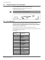
6.2
Programming the voice messages
You can switch between two modes using the slide switch:
z Normal (default setting): internal speaker deactivated
z Test: internal speaker activated
When you leave the room, set the voice board to Normal mode.
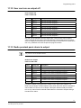
6.2.1
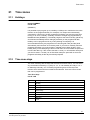
Pre-configuration
There are two types of messages: Command control messages and alarm
messages. Command Control messages are used to give voice status information
when a user dials in to arm/disarm the system or to control outputs, zones and
additional events (using DTMF codes).
Alarm messages are assigned to alarm events and allow voice alarm.
Before programming the Command Control messages it is recommended to record
the messages and put them in a list.
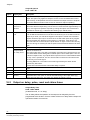
For example:
Message No.
Voice Message
Order of recording
1
Output 4 on
2
Output 4 off
3
Output on
4
Output off
5
Area A armed
6
Area A disarmed
7
Area B armed
8
Area B disarmed
9
Zone 1 alarm
10
Zone 2 alarm
11
Zone 3 alarm
12
Mains failure
13
Mains restored
14
Battery low
15
Battery restored
…
37
34
Building Technologies
Fire Safety & Security Products
Tamper
Voice board IAV6-90
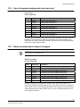
Command control messages for output control on/off and area arm/disarm will need two voice
messages to be assigned. (One for ON confirmation and one for OFF confirmation.) These messages
need to be in direct sequence.
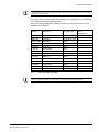
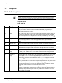
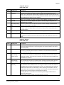
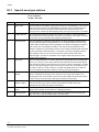
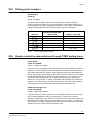
Use Table 1 below to assign each event address to the appropriate voice message
in accordance with the list you have made.
Each event can be assigned a message number from 0-99. When set to "0" the
message will be disabled.
Address
Description
Message Type
Value
(message no.)
P42E 1-8E
Outputs
Command control
0
P64E 1-2E
Areas A&B
Command control
0
P160E 1-16E
Zone alarm
Alarm
0
P176E 1E
Keypad or radio panic alarm Alarm
0
P176E 2E
Fire alarm
Alarm
0
P176E 3E
Medical alarm
Alarm
0
P176E 4E
Mains failure
Alarm
0
P176E 5E
Mains restored
Alarm
0
P176E 6E
Battery low
Alarm
0
P176E 7E
Battery restored
Alarm
0
P176E 8E
Tamper
Alarm
0
P176E 9E
Duress alarm
Alarm
0
P176E 10E
Latchkey disarm
Alarm
0
P176E 11E
Manual test initiated
Command control
0
Tab. 1
List of message addresses
For Output command control and area command control assign the first message number, e.g.
P42E 1E 1 assigns messages 1 and 2 to output 1 (confirming ON and OFF respectively).
35
Building Technologies
Fire Safety & Security Products
Voice board IAV6-90
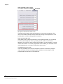
6.2.2
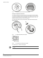
Recording messages
Before programming your voice messages:
Make a list of the messages to be sent for the individual alarm types and assign each of them a
message number. These messages should then be recorded in the same order in which they are
written down.
Once you have installed the Voice Board you can record your personalized speech
messages on the module:
1.
Set the slide switch to NORM.
2.
Press the Reset button in order to set the alarm message counter to zero.
3.
Press and hold the Record button while recording the message.
Î
The Record LED on the 2-way voice board lights up.
The individual messages must be at least 2 seconds long but no longer than 30 seconds.
4.
Speak clearly into the microphone (from a distance of 10 - 20 cm).
5.
When you have finished recording your message, release the Record button
to stop the recording.
Î
6.2.3
6.2.4
The record LED on the 2-way voice board goes out.
6.
Press the Record button again to record another message immediately after
the previous message.
7.
Continue making recordings until you have recorded all the messages.
Playing messages
1.
Press the Reset button on the Voice Board to go to the beginning of the
messages.
2.
Set the slide switch to Test before listening to the recorded messages.
3.
Press the Play button once to start playing the first message.
4.
At the end of the recorded message playback will be stopped.
5.
To listen to the next recorded message press the Play button again.
6.
Repeat this operation until all the relevant recorded messages have been
reviewed.
7.
Press the Reset button to reset the voice board to the beginning of the
messages.
8.
Set the slide switch back to NORM mode.
Re-recording messages
36
Building Technologies
Fire Safety & Security Products
1.
Press the Reset button on the Voice Board to go to the beginning of the
messages.
2.
Re-record your message as described in chapter 6.2.1: Pre-configuration.
Voice board IAV6-90
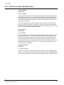
6.3
Operating instructions
The IAV6-90 is available in 2 versions. Both versions can be configured remotely and allow the
configuration of a phone number the system will call in the event of an alarm.
Version 9.07 additionally allows a Central Monitoring Station (CMS) to verify an alarm by listening in
after the alarm has been reported by the Control Panel.
The IAV6-90 Voice Board enables the following functionality of the Control Panel:
z Reporting using voice messages
z Alarm verification
z Remote configuration of the system
z Remote listen-in/talk-in
The two basic applications of Sintony 60 for reporting alarms are
z Reporting to a user phone
z Reporting to a CMS
The voice board supports both scenarios. It offers two modes of operation in both
scenarios, which differ mainly in the way the listen-in voice call is established:
z Holding the line open
z Auto answering
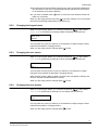
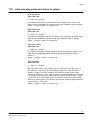
6.3.1
Alarm reporting to a user phone
6.3.1.1 Holding the line open following Domestic/Speech reporting for DTMF control
Dialer B option
P175E 2E
(Option 6 set ON)
The messages received must always be confirmed by a user by pressing #. Otherwise there may be
delays in the transmission of further alarm messages.
The dialer is set to call Domestic (Alarm tones only) or Speech (recorded
message).
After an event has occurred, the Control Panel's dialer calls the user (regular
telephone number) to report the event by sending a voice message or alarm tones
over the phone. If a kiss-off is sent (dialer acknowledge DTMF code set by the user
by parameter P175E 14E; if no kiss-off is programmed, the default DTMF is #), the
dialer will keep the telephone line open.
The user at the phone can then talk to the person at the site and listen in to the site
by using DTMF commands to turn the microphone on and off. If no kiss-off is sent
to the Control Panel by the user after having answered the call, the dialer will
repeat the call to the telephone several times (set by parameter P184E 1-8E).
Once the microphone is turned ON, the panel will keep the conversation for 1 minute. To extend the
call for a longer time, the user must press the * button before the first minute has passed. The panel
will close the microphone but not the call. If the * button is pressed once more, the panel will open the
microphone again for 1 minute.
This action can be repeated several times.
37
Building Technologies
Fire Safety & Security Products
Voice board IAV6-90
6.3.1.2 Auto answering
Auto Ring Count
P175E 3E
(Value 0-99)
A user can call the Control Panel from any telephone. After a preset number of
rings (pre-programmed by parameter P175E 3E) the Control Panel will hold the
line and a series of tones will be sent over the line (tone and quiet time, tone and
quiet time, etc. like answering of a fax machine). The user can enter into listen-in
mode by entering the same DTMF code which activates the microphone (see
above) during the quiet time between the incoming tones.
6.3.2
Alarm reporting to the Central Monitoring Station (CMS)
Only available in version 9.07 or higher.
This mode allows a person at the CMS to verify an alarm by listening in after the
alarm has been reported by the Control Panel. With this feature there are 2 modes
of operation:
6.3.2.1 Direct on-line for CID or SIA
Telephone number 5 reporting options
P183E 1-8E 5E
In order to activate this mode, option 5 at P183E must be ON.
If this option is turned ON and a full duplex two-way voice board is fitted, the panel
will send a command to the CMS in CID or SIA format to tell the operator at the
CMS to stay on-line so he can listen in or talk to the site (full-duplex two-way
communication).
The Control Panel will hold the line after reporting to the CMS by CID or SIA.
This function should not be used with the function “speech protocol”.
38
Building Technologies
Fire Safety & Security Products
Voice board IAV6-90
6.3.2.2 Call-back
In order to activate this mode, option 5 at P183E must be OFF and option 8 at P175E 2E must be ON.
Dialer B options
P175E 2E 8
After reporting the event to the CMS the Control Panel rings off.
When this option is turned on, the Control Panel will ring off after reporting to the
CMS. The operator at CMS can then call the Control Panel during a period
10 minutes. The panel will answer the incoming call on the first ring.
If the DTMF code defined by parameter P175E 14E (as described above) is not
entered within 30 seconds, the panel will ring off. The panel will still answer any
new calls on the first ring within the 10 minutes after the original alarm was
transmitted. As soon as the panel receives the correct DTMF acknowledge code
the auto-answer feature (answering on the 1st ring) will be reset.
After the Control Panel has answered an incoming call, a short beep will sound at intervals of
5 seconds for a period of 30 seconds. If nothing happens and the 30 seconds timer expires, the panel
will ring off. If however the DTMF code programmed by parameter P175E 14E is entered before the
30 seconds timer has expired (for example if a code "1234" was programmed by parameter
P175E 14E, then the operator must enter 1-2-3-4-# at their telephone), the call will be extended. The
short beeps will stop and the two-way voice channel will remain open for 3 minutes (if no code has
been programmed at P175E 14E, the call can be extended by pressing the # button). After 2 minutes
and 30 seconds the short beeps will start again. The operator must repeat the above process to keep
the panel on-line for a further 3 minutes, otherwise the panel will ring off when the 3 minutes are over.
If the operator wishes to terminate the two-way voice connection, he should enter
0-0-0-# on his telephone which will tell the panel to ring off.
6.3.3
Additional commands available for Voice Board
6.3.3.1 Output DTMF
Output DTMF
P175E 12E 0-9999E
(Value 1-4 digit code 0-9999)
The panel can be configured to allow remote operation of the outputs via a remote
telephone. The code programmed at this address is the DTMF code that must be
used when performing this function. When dialing the panel and it has answered
the call, after waiting for the panel modem tones to stop you can enter in the 4 digit
DTMF code plus the output number you wish to control, e.g. 1 for output # 1, and
the current status will be given of the output associated with the code entered.
After that, if you press the <*> button on the telephone the status of the output will
toggle e.g. if it was previously on it will change to off or vice versa. When finished
you simply hang-up and 15 seconds later the panel will release the line.
39
Building Technologies
Fire Safety & Security Products
Voice board IAV6-90
6.3.3.2 Listen-in control code
Monitor DTMF
P175E 13E
The panel can be configured to allow remote listen-in via an on-site microphone.
The Voice Board must be fitted for the microphone feature to be available. The
code programmed by parameter P175E 13E is the DTMF code to be used when
turning the microphone on or off. When dialing the panel and after it has answered
the call, the user must wait for the panel modem tones to stop. Then he can enter
the max. 4-digit DTMF code and press the <*> button on the telephone. This will
turn the microphone on. Pressing the <*> button again will turn the microphone off.
When you have finished, just ring off and 15 seconds later the panel will release
the line.
6.3.3.3 Dialer acknowledge DTMF code number
DTMF Acknowledge Code
P175E 14E
If the panel is set to report in Domestic (Alarm tones only) or Speech (recorded
message) reporting formats, the user can simply kiss-off (acknowledge) the alarm
by pressing the <#> button on the remote telephone.
Alternatively if the user requires a more secure kiss-off method to ensure that the
alarm is only kissed off by the correct person the user can program a 1-4 digit code
at P175E 14E location. After a code is programmed at that location, the user must
enter the code followed by the <#> button to kiss-off the alarm event. The same
code is also used in conjunction with the two-way voice functions.
6.3.3.4 Force test call DTMF code number
DTMF call code
P175E 15E
If a user wishes to remotely force a test call from the panel to a CMS using the
Contact ID test message, the user can dial the Control Panel from a remote
telephone and when it answers enter the code programmed by parameter
P175E 15E on the telephone.
If a voice board is fitted the user can assign a voice message (see chapter 22.8:
Manual test call initiated voice message number; P176E 11E) to indicate that the
function has started. If no voice board is fitted the user will hear 3 short beeps after
the code has been entered to indicate that the function has started. Once the user
hangs up, the panel will make a call to the CMS and send a manual test call
message. If no code is programmed at P175E 15E location (i.e. 0) the function will
be disabled. The code can be 1 to 4 digits long as required.
It is also possible to force a locally generated test call from the Control Panel
keypad by pressing and holding the
button and then pressing the
together
with the . This will force a test call to the CMS.
Ctrl
Ctrl
40
Building Technologies
Fire Safety & Security Products
Voice board IAV6-90
6.3.4
DTMF code table
The following DTMF codes are used for sending responses and operating
commands.
Command
Default
P175E 12E
2
Sets the DTMF code for use by the CMS to operate the
OUTPUT (1-4 digits).
P175E 13E
1
Sets the DTMF code for turning the microphone ON/OFF.
P175E 14E
#
Dialer acknowledge DTMF code
P175E 15E
99
Forces a test call for testing the DTMF response codes
(AREA A/B).
P63E 1-2E
Tab. 2
6.4
Description
Sets the DTMF code for ARM and DISARM.
List of DTMF codes
Mute siren
Valid as of version 9.07:
This option must be programmed to mute all acoustic devices automatically during
listen-in with the full duplex two way voice board.
According EN 50131-3 if an alarm occurred during Exit Delay the dialer should
reported only after 30sec.
Only output 1 and the keypad buzzers are automatically muted. If an external siren is connected to
another output this will not work.
6.5
Domestic kiss-off / Auto kiss-off
Domestic Kissoff
183E 6E
Auto Kiss-off for Voice/Domestic reporting: if Voice or Domestic Report Format is
used and this option is turned On, the alarm will be reported and it can be kissed
off by entering the kiss-off code (P175E 14E) at the telephone but if not kissed off
the event is automatically removed from the dialer buffer once the maximum dial
re-tries has been reached for the telephone number. A new event must then be
created before the dialer will dial again.
We recommend using this function if a customer does not want to acknowledge alarm messages
manually.
Please note: the dialler stops after the first alarm message.
41
Building Technologies
Fire Safety & Security Products
Extension modules for Sintony 60 control panel
7
Extension modules for Sintony 60 control panel
Various extension units could be connected to the Sintony 60 to expand the
functionality.
7.1
Output module 12V/1A IRO6-04 (Output 5-8)
With this extension PCB the Sintony 60 could be extended with additional 4 Relays
to a maximum of 8 Outputs. Each relay could switch a max. power of 12V/1A.
The connection to the Sintony 60 control panel is realized over the system bus.
Therefore it is an intelligent member of the Bus and could be programmed over the
control panel. It could be installed either directly in the control panel (Sintony 60Mmodular only) or external. The terminals are connected to corresponding terminals
on the remote devices marked POS, NEG, CLOCK, & DATA.
Max. 2 boards can be connected (max. 8 outputs total).
7.2
Zone expander module IZE6-04
This Module makes zone doubling and EOL end of line resistor connections very
easy. It contains all necessary resistors to expand the control panel and offers
clearly marked terminal blocks for 2 line in and 4 lines out. This module can be
used instead of the in the delivering included separate resistors and to save
installation costs if placed outside the control unit. (less cabling needed) Maximum
4 expander modules could be used per control panel.
7.3
Radio receiver IRFW6
The IC60 panel can have wireless capability via the IRFW6 receiver module
(Sintony 60 modular optional, Sintony 60 compact already build in).
The receiver will add wireless capability to your system in the form of wireless
Alarm sensors and wireless Remote controls. The IRFW6 connects to the system
bus port as the keypads and the other intelligent bus participants of the system.
The IRFW6 is available in 2 frequencies, 868MHz and 915MHz. Up to 2 IRFW6
can be connected to the panel to increase the coverage range if desired. The red
LED fitted to the IRFW6 receiver will flash at 1 second intervals when in Learn
Mode (see chapter 12.1: Learn a remote control / radio pendant; Pendant learn;
P18E & 20.12: Learn a wireless detector / code to the system; Zone Learn Radio;
P164E). The LED will also turn on when it is receiving an actual radio transmission
(on steady). It could be installed either directly in the control panel (Sintony 60Mmodular only) or external. The terminals are connected to corresponding terminals
on the remote devices marked POS, NEG, CLOCK, & DATA. In the Sintony 60
compact is the radio receiver normally already integrated (could vary in different
countries), but a second receiver IRFW6 can also be connected externally through
the bus to increase the coverage range if desired.
42
Building Technologies
Fire Safety & Security Products
LCD keypad
8
LCD keypad
To operate the Control Panel Sintony 60 you need a Keypad which allows you to
program and manipulate the systems and show all information on a big LCD
Display in clear text. This Keypad is already included in the Sintony 60 compact
version, where it works in the Sintony 60 modular as a separate stand alone unit
with Bus connections.
8.1
Technical data
Fig. 15
LCD Keypad
Current consumption of the LCD Keypad type IKP6
z Normal state: it depend on the volume of the Backlight LED/ Display
z Min.: 35 mA, Typical: 60 mA, Max.: 90 mA
z Battery state: While the AC fail the software (default setting) turnoff the backlight
LED’s and Display so in this mode the current consumption is 35 mA.
Maximum 8 Keypads/Card readers can be connected to one Control Panel Sintony 60.
Bus connections- max. length*
8.2
Up to 25 meter, 22AWG,
wire diameter 0.6 mm
7 Keypads IKP6-03 or
Reader IAR6-30
8 Keypads IKP6-03 or
Reader IAR6-30
Up to 100 meter, 20AWG,
wire diameter 0.8 mm
4 Keypads IKP6-03 or
Reader IAR6-30
4 Keypads IKP6-03 or
Reader IAR6-30
Installing and addressing a LCD keypad to the system
For detailed installation instructions please refer to the installation leaflet which is
delivered with the LCD Keypad.
43
Building Technologies
Fire Safety & Security Products
LCD keypad
8.2.1
LCD keypad Installation
Bus connection
The connection to the Sintony 60 control panel is realized over the system bus. It is
an intelligent member of the Bus with a unique Bus address (refer to Keypad Set
up). It could be installed external to the Sintony 60 Control Panel (modular and
compact version). The terminals are connected with a 4 wire cable to the
corresponding terminals on the Control Panel marked POS, NEG, CLOCK, &
DATA.
The 5th bus wire- Listen dialing function
The 5th wire is an optional Listen-dialing connection. It is connected from the LIN
terminal of the keypad to the Lin terminal of the panel keypad port. With the Listenin wire connected the user is able to hear the call progress during dialing at the
keypad (only if the program options at address P175E 6E are turned on).
Maximum cable length
The maximum recommended cable using standard 0.6mm security cable is 25m.
Cable runs exceeding this distance may require 0.8mm cable. Always use good
quality cable. Some installations may require CAT5 data cable to ensure data
integrity in noisy sites.
Keypad Tamper Switch
The LCD keypad has a tamper switch at the back side. Make sure that when the
Keypad is installed the Tamper contact is closed by the pressure of the wall. If the
switch needs some adjustment, the tamper contact could be fitted with an
additional distance screw to ensure proper contact to the wall and therefore a good
protection of the housing against manipulation.
Activation- programming - addressing
A LCD Keypad has to be learned to the system. To start after installations with the
first steps please refer to the chapter 8.4: Programming a keypad to the system –
addressing. This contains:
z Change language
z Address the keypad to the system bus
z Copy text files into the new Keypad
8.3
Programming a LCD keypad – Local program mode
The Keypad can be programmed locally via the Keypad buttons or by a PC with
the separate available programming cable IAQ6-1 and the programming Software
Sylcom 60 IAS6-1 through the programming interface port on the back side of the
Keypad. (It could also be programmed remotely through the programming port of
the control panel unit if connected to the bus).
In the local program Mode object related names like Zones, Users, Outputs etc.
can be programmed. System settings have to be programmed in the Installer
Program Mode (see chapter 9.4.1: Access to installer program mode).
44
Building Technologies
Fire Safety & Security Products
LCD keypad
8.3.1
Accessing local program mode
z To enter Local program Mode on a LCD Keypad press
Ctrl
followed by
.Hold
for 2 seconds.
Î The display will now show Local Mode kb # where the # equals the keypad
address.
You must press the
button first and the
button must be pressed within 2 seconds of pressing the
Control button. If you make a mistake press the
button then repeat the process.
Ctrl
There are two ways to program the keypad in Local program Mode.
z You can use the menu function to navigate through all of the program options.
z You can enter in the program location directly from the list below.
The menus are described on the following pages.
8.3.2
Local program mode menu tree
PROGRAM MODE
Ctrl
+
LOCAL MODE KB 1
USER NAMES
____________________
◄ ► ◄┘
LOCAL MODE KB 1
PANEL NAME
____________________
◄ ► ◄┘
LOCAL MODE KB 1
AREA ID
____________________
◄ ► ◄┘
LOCAL MODE KB 1
EXIT PROGRAMMING
____________________
◄ ► ◄┘
LOCAL MODE KB 1
KEYPAD NUMBER
____________________
◄ ► ◄┘
◄ ► ◄┘
LOCAL MODE KB 1
DEFAULT ALL TEXT
____________________
LOCAL MODE KB 1
PANEL TYPE
____________________
◄ ► ◄┘
◄ ► ◄┘
LOCAL MODE KB 1
UPDATE ALL KEYPADS
____________________
◄ ► ◄┘
LOCAL MODE KB 1
LANGUAGE
____________________
LOCAL MODE KB 1
ZONE NAMES
____________________
◄ ► ◄┘
Fig. 16
LOCAL MODE KB 1
AREA NAMES
____________________
◄ ► ◄┘
LOCAL MODE KB 1
OUTPUT NAMES
____________________
◄ ► ◄┘
LCD - Local program Mode - Menu Headings
45
Building Technologies
Fire Safety & Security Products
LCD keypad
Fig. 17
Menu Tree
When you are at the desired main menu heading, press
program location.
46
Building Technologies
Fire Safety & Security Products
to access the data
LCD keypad
8.3.3
Local program mode direct program addresses
To access directly to the address via the Keypad buttons, without scrolling through
all the menu points you can use a shortcut by adding they following addresses
directly.
Sequence
Action
P1E
ZONE #1 TEXT (maximum 16 characters)
P16E
ZONE #16 TEXT
P800E
UPDATE EDITABLE TEXT TO ALL LCD KEYPADS
P801E
RETURN ALL EDITABLE TEXT TO DEFAULT
P995E
PANEL TYPE
P996E
SET KEYPAD ADDRESS NUMBER FROM 1-8
P997E
KEYPAD LANGUAGE
P998E
AREA IDENTIFYING CHARACTER (assigning numbers or letters to
Areas)
P999E
PANEL NAME DISPLAY (maximum 16 characters)
P1001E
PROGRAM USER 1 NAME
P1100E
PROGRAM USER 100 NAME
P2001E
AREA A IDENTIFYING NAME (maximum 16 character Area name)
P2002E
AREA B IDENTIFYING NAME (maximum 16 character Area name)
P3001E
PROGRAM OUTPUT 1 NAME
P3008E
PROGRAM OUTPUT 8 NAME
Tab. 3
8.3.4
Shortcut programming codes Local program mode
Exiting local edit program mode
Press and hold the
button for 2 seconds and the LCD keypad will leave Local
Program Mode and return to normal Mode or; press the
button repeatedly until
the display reads Exit Programming, then press the
button to exit program
mode.
Ctrl
Ctrl
8.4
Programming a keypad to the system – addressing
All following programming steps in this chapter are requesting the Local Program
Mode as described before.
47
Building Technologies
Fire Safety & Security Products
LCD keypad
8.4.1
Language change of LCD
Before starting to program the System it will be very useful to change the display
language to the language that you prefer. The system is able to operate in different
languages and is delivered in the standard version with the setting in English.
Available Languages are:
z English
z Spanish
z French
z Italian
z German
z Portuguese
z Polish
z Norwegian
z Dutch
z Turkish
z Belgium
z Czech
z Swedish (only valid as of version 9.07)
When in Local Program Mode, you scroll with the buttons
/
to the position
Language or go directly by pressing P997E, the display will look like this:
Language
English (ENG)
Scroll with the buttons
/
to the language you prefer.
When you are happy with the changes press
to save.
If you change to a language menu that you do not understand it could be difficult to find back to the
right address to change back to your preferred language. We recommend to get out of the
programming mode (pressing
for more than 2 seconds). And start the above described shortcut
function again:
Prog
1. Local program Mode
2. press P997E
3. scroll up/down
48
Building Technologies
Fire Safety & Security Products
Ctrl
+
for 2 sec.
LCD keypad
8.4.2
LCD keypad address assignment
A total of 8 devices (keypads or proximity readers) can be connected to the control
panel. Each keypad must be addressed individually to avoid bus conflicts when
multiple users are operating different keypads simultaneously. By default, each
keypad comes addressed as KP # 1.
When in Local Program Mode, you scroll with the buttons
/
to the position
Keypad Number or go directly by pressing P996E, the display will look like this:
Keypad Number 1
z Select an unused address, e.g. 2 then press
to save.
z To exit Local Program Mode, press and hold the
Prog
button for two seconds.
If you do not assign a unique address to every keypad and reader connected to the keypad bus, a
conflict will exist that will cause erratic operation. Each reader or keypad MUST have a different
address.
8.4.3
Copying text to another LCD keypad
The individual programmed wording, as described in the chapter 8.5: Changing
names – personalization of the system, is stored locally at one Keypad. This allows
operating more than one Keypad within one system, where each can name
functions differently. This could make sense if more than one user is sharing a
system. Each keypad could also be operated in a different language within one
system (12 different languages available. Refer to chapter 8.4.1: Language change
of LCD).
If more than one LCD keypad is connected to the control panel, and the existing
edited text from one LCD keypad should appear on all other LCD keypads, than
the text could be easily copied. This function is particular helpful if already installed
systems are expanded.
z When you enter in P800E, all of the customizable text at the keypad will be
transferred to all other LCD keypads connected to the control panel.
z There is also an alternative method to transfer the text. Pressing the
button
for 2 seconds while in Local Edit Mode will perform the transfer. The text in your
keypad will be transferred to all other LCD keypads connected to the panel.
8.5
Changing names – personalization of the system
To make the Sintony 60 an individual system that fits exactly to the environment of
the user, we recommend changing the general names to Object-related, easy to
identify wordings.
e.g. instead of showing only Alarm in Zone 1 at the display the LCD text could
be individualized to Alarm Kitchen, or Keypad Office or instead of showing
User24- personalized names like Grandmother, or Thomas. This normally helps
the user to operate the system much easier.
To change any names the system must be in the local programming mode. Press the
button first
and the
button must be pressed within 2 seconds of pressing the
button. If you make a mistake
press the
button then repeat the process.
Ctrl
Ctrl
49
Building Technologies
Fire Safety & Security Products
LCD keypad
8.5.1
How to use the alphanumeric keypad buttons
z When in Local Program Mode, you scroll with the buttons
/
to the position
where you wish to change the name e.g. Zone Names the display will look like
this:
Local Mode Kb 1
Zone Names
z By pressing the
button the display will show the Zone 1 which you can now
select by using the / buttons to the Zone that should be renamed e.g. Zone
1-16.
z If the right Zone is indicated press
again and the display will show:
Zone 1 <A.Z>
Zone 1
The Cursor will be underneath the first letter to be edited (in this case the Z).The
letters A.Z indicate that the letters selected by the numeric buttons (<0-9>) will be
in capitals.
z By pressing the
button once, the display will change to a.z indicating that
the letters selected by the numeric buttons (<0-9>) will be lower case.
z You can cycle back to another selection by pressing the
button.
Once you have selected the desired font you can now proceed to change the text.
The following table shows the English characters that can be selected by each
numeric button. (standard telephone keypad)
The lower case options are shown in ( ).
▼Button #
1st Press
2nd Press
3rd Press
4th Press
1
* (‘)
# (<)
= (>)
1
2
A (a)
B (b)
C (c)
2
3
D (d)
E (e)
F (f)
3
4
G (g)
H (h)
I (i)
4
5
J (j)
K (k)
L (l)
5
6
M (m)
N (n)
O (o)
6
7
P (p)
Q (q)
R (r)
7
8
S (s)
T (t)
U (u)
8
9
V (v)
W (w)
X (x)
9
0
Blank
Y (y)
Z (z)
0
There are four different selections per button.
z By pressing the button once, a character will appear in the display (see “1st
press” column below). Pressing the same button again will cause the display to
change to the next character in the sequence (see “2nd press” column).
z After you have pressed the same button four times the next press (5th) will
cause the display to wrap back to the beginning.
z Once you have selected the first character, press the
cursor one position to the right.
50
Building Technologies
Fire Safety & Security Products
button to move the
LCD keypad
z Now select the second character and move the cursor to the right repeating the
process until all of the text is completed (Remember that there are a maximum
of 16 characters per program address).
z If you make a mistake use the
button to move the cursor towards the left and
make any corrections.
When you are happy with the text press
to save the changes. You can program
the text for all following identifications in the same way.
8.5.2
Changing the keypad name
When in Local Program Mode, you scroll with the buttons
/
to the position
Panel Name or go directly by pressing P999E, the display will look like this:
Name <A.Z>
Siemens
You may enter any name you wish up to 16 characters in length (using the same
method as described in changing names).
When you are happy with the changes press
8.5.3
to save.
Changing the user names
When in Local Program Mode, you scroll with the buttons
/
to the position
User Name or go directly by pressing P1001E, the display will look like this:
User 1 <A.Z>
User 1
You may enter now the person’s name you wish up to 16 characters in length
(using the same method as described in changing names).
When viewing events in Memory Mode, the User name will appear to identify who
the user was that Armed/Disarmed the system.
When you are happy with the changes press
8.5.4
to save.
Changing the zone names
When in Local Program Mode, you scroll with the buttons
/
to the position
Zone Name or go directly by pressing P1E, the display will look like this:
Zone 1 <A.Z>
Zone 1
You may enter any name you wish up to 16 characters in length (using the same
method as described in changing names).
When you are happy with the changes press
to save.
51
Building Technologies
Fire Safety & Security Products
LCD keypad
8.5.5
Changing the keypad area name
When in Local Program Mode, you scroll with the buttons
/
to the position
Area Name or go directly by pressing P2001E, the display will look like this:
Area 1 <A.Z>
Area A
You may enter any name you wish up to 16 characters in length (using the same
method as described in changing names). If you program in a name for the area,
this name will appear when displaying events in memory display mode.
When you are happy with the changes press
8.5.6
to save.
Changing the output names
When in Local Program Mode, you scroll with the buttons
/
to the position
Area Name or go directly by pressing P3001E, the display will look like this:
Out 1 <A.Z>
Output 1
You may enter any name for that output you wish up to 16 characters in length
(using the same method as described in changing names). When viewing events in
Memory Mode, the output name will appear to identify what function the output is
controlling. (e.g. Garage door, lights garden etc.)
When you are happy with the changes press
8.5.7
to save.
Changing the area single character identifier
When in Local Program Mode, you scroll with the buttons
/
to the position
Area Id or go directly by pressing P998E, the display will look like this:
Area ID <A.Z>
ABCDEFGHIJKLMNOP
You may edit the single character Area identifier at this address starting at Area A
(first left-hand position). The keypad allows for up to 16 areas but the actual
number of areas supported on this panel is two. The first character (in this case the
A) is the identifier used to show the status of the first Area when armed. The
second position (in this case the B) is the identifier used to show the status of the
second Area. If you preferred to have the first area shown as Area 1 and not A
then you can change it here using the same method as used previously. With the
cursor underneath the letter A, press the
button four times until the character in
the first slot shows 1.
When you are happy with the changes press
52
Building Technologies
Fire Safety & Security Products
to save.
LCD keypad
8.5.8
Resetting individual text to default or last saved setting
While in Local Edit Mode there are two special functions that can be performed at
any of the Local Edit Program locations. They are Return to Default Text or
Return to Previously Saved Text.
For Example, to Return the Zone 1 text back to Defaults;
z If during the programming of Zone 1 text P1E you wished to return back to the
default text, simply Press and hold the B button for 2 seconds, and the text will
return to the default settings.
z If you wished to return to the last saved version of the text simply Press and hold
the
button for 2 seconds and the last saved text for zone one will appear.
If the last saved version of text for Zone 1 was in fact the default setting, then pressing
will return the default text anyway.
8.5.9
Ctrl
then
or
Resetting all text to default
While in Local Edit Mode it is possible to restore all of the customizable text fields
to the factory default settings.
When you enter in P801E display will prompt you to press 801E again. Once you
have pressed 801 , all customizable text (e.g. zone names, user names, output
names, etc) will be returned to the default text.
8.6
Operating a LCD keypad
8.6.1
LCD keypad view memory mode
When displaying Memory Events in Memory Mode the Display will show the events
using plain text messages with the time & date that the event occurred. This makes
the fault diagnosis much easier. All events can be displayed (including when the
system was disarmed and by whom). To access Memory Mode, press the
button.
There are two parts to the Memory Display Mode:
8.6.2
Current system alarms
If there are any current system alarms, they will be displayed first under the
heading of Check System. When the
button is pressed, the current system
alarms will be displayed in plain text to describe the actual problem. If there is more
than one current problem the keypad will display event alarm sequentially with the
heading of Current Alarms on the top line and the alarm on the bottom line.
Each time the
button is pressed, the next alarm will be displayed. If there are
no system problems with the panel the display will show No Faults. When all
current system alarms have been displayed the keypad will then start to show the
historical memory events.
53
Building Technologies
Fire Safety & Security Products
LCD keypad
8.6.3
Historical memory event
Following the Current System Alarms the panel will display the historical memory
events. The panel stores the most recent events, (up to 255), including all alarm
events, all system events such as mains failure etc as well as arm/disarm by User
& Area. The memory events are displayed via the LCD keypad with the most
recent event shown first and subsequent events following in descending order from
newest to oldest.
During the Historical Memory Event display mode the LCD display will show the
type of event on the top line e.g. Area A armed by User 1 and the actual time
and date that the event occurred on the bottom line.
To view events simply press the
button. The keypad will beep and the display is
advanced to the next event every time the
button is pressed.
If you wish to go back and look at an earlier event you can use the
button to go
back to an earlier event. Each time the
is pressed the memory will go back one
event.
To cancel the memory displays just press
.
If the
button is not pressed, the keypad will automatically exit memory display
mode after approximately 20 seconds.
When there is a new event in memory the words System Check will be shown on
the LCD.
The System Check display will be reset- change to System OK once the event
has been viewed.
8.6.4
LCD quick view mode
If any zones are unsealed when disarmed the LCD keypad will scroll through each
unsealed zone displaying the 16 character name for each zone. If a number of
zones are unsealed simultaneously it can take sometime for the display to show all
of the unsealed zones.
By pressing the
button when zones are unsealed the keypad will enter the
Quick-view Mode. When in Quick-view Mode, each unsealed zone is displayed as
a single two digit number e.g. 01 05 10. Up to 5 unsealed zones maybe
displayed at one time. If more than 5 zones are unsealed at the time the display
will scroll to the next bank of 5 zones so the user can see quickly which zones are
unsealed. To exit Quick-view Mode you simply press the
button again or the
keypad will time out automatically in approximately 30 seconds.
54
Building Technologies
Fire Safety & Security Products
LCD keypad
8.6.5
Arming or disarming two areas at a keypad
If the panel is configured for two areas A&B, and the option Arm button
required before code is turned on (P45E Option 1), there are a number of
possible arming options.
z If a user code is only assigned to one area and they pressing
Code and pressing
Arm.
, entering the
at the keypad, only the Area assigned to their code will
z If a user code is assigned to both areas but the keypad being used is only
assigned to one area, pressing
, entering the Code and pressing
arm the area assigned to the keypad.
will only
z If a user code is assigned to both areas and the keypad being used is also
assigned to both areas, pressing , entering the Code and pressing
will put
the keypad into a Ready to Arm state. On the LCD keypad the display will show
Area/s to Arm A B.
z If you press the
button now, both areas A&B will arm. If before pressing the
button you wish to deselect one of the Areas e.g. if you only want to arm area
B press the number
and Area A will disappear on the LCD keypad display,
indicating that only area B will arm when the
button is pressed.
On disarming, after entering the Code an pressing
the display on the LCD
keypad will show Area/s to Disarm A B. You can press the
button at this
point to disarm both areas, select which area you wish to disarm by using the
numbers
&
on the keypad, or if you don’t do anything the panel will proceed
with disarming both areas after 10 seconds time has elapsed.
8.6.6
Toggle chime mode on-off
On the LCD Keypad there is a
button. Pressing and holding that button for
2 seconds will toggle Chime Mode from On-Off or Off-On.
8.6.7
Send manual test call
If the panel is configured for Contact ID reporting and test calls are programmed to
report, you can force a manual test call by pressing and holding
followed within
2 seconds by . This will cause a manual test call to be sent to the monitoring
company. You can also dial into the panel from a remote site and using the
telephone cause a manual test call remotely. For details see chapter 22.7: Forced
test call code options; P175E 15E and chapter 22.8: Manual test call initiated voice
message number; P176E 11E.
Ctrl
8.6.8
Manual answer an incoming call
If the panel is not configured to answer in-coming calls, the user can force it to
answer the call by pressing and holding
followed within 2 seconds by . This
will make the panel answer the call immediately. For this function to work the
phone line must be ringing at the time and there must have been at least two rings
before pressing the buttons.
Ctrl
55
Building Technologies
Fire Safety & Security Products
LCD keypad
8.7
System settings of the LCD keypad
The Keypad offers various parameters to be easy adjusted. These functions are
also described in the user manual and can be operated all the time without a code.
In the standard configuration the Backlights and the buzzer are always on. Only if a
mains failure occurs the backlight will be turned off to save power of the backup
battery.
All lights on the Keypad and the buzzer can be turned off locally with these functions on each Keypad
differently. If a malfunction regarding back light or no buzzer tone is reported by a customer, check
these options first.
8.7.1
LCD backlight adjustment
Increasing the LCD backlight:
z By holding down the
button and repeatedly pressing the
backlight level can be increased to the maximum.
Ctrl
button the LCD
Reducing the LCD backlight:
z By holding down the
button and repeatedly pressing the button the LCD
backlight level can be decreased to the minimum which is until function light off.
8.7.2
Ctrl
Keypad button backlight adjustment
Increasing the keypad button backlight
z By holding down the
button and repeatedly pressing the
button the
keypad LED backlight level can be increased to the maximum.
Ctrl
Decreasing the keypad button backlight
z By holding down the
button and repeatedly pressing the
button the
keypad LED backlight level can be decreased to the minimum, which is until
function light off.
8.7.3
Ctrl
Volume adjustment of the keypad buzzer
z Hold down the
Ctrl
button.
z By repeatedly pressing the
button the volume of the buzzer tone can be
increased.
z By repeatedly pressing the
button the volume of the buzzer tone can be
decreased, which is until function sound off.
56
Building Technologies
Fire Safety & Security Products
How to program the alarm system
9
How to program the alarm system
To program the Control Panel the System can be programmed in 4 different ways
locally or remotely through a telephone line connection.
9.1
Programming the system by PC
With the separate available programming cable IAQ6-1 and the programming
Software Sylcom 60 IAS6-1 the system could be programmed very comfortably
through the programming interface port on the control panel PCB (to access this
port the panel must be opened).Or it could also be programmed remotely through
the programming port of the control panel unit if connected to the phone line).
For more details refer to the separate available Software description.
When the system is plugged/ unplugged to the PC it could happen that the system does a restart
automatically. We recommend to plug and unplug always under powerless condition (battery and main
disconnected from the panel to avoid damage).
9.2
Programming the system remotely
If the control panel is connected to a telephone line, it could be programmed also
remotely with a PC.
There are certain security levels build in, to assure that only authorized user will
get access to the control panel. It could also be programmed that the owner of the
system has to authorize the remote access by entering a code.
For example will the panel never allow direct access from external callers through
the telephone line, but will call back only to the number which is programmed as
authorized user locally in the control panel. This function is normally used by
Central monitoring stations. The connection is done through a telephone modem
and a PC (see chapter 9.1: Programming the system by PC).
9.3
Programming the system by memory stick
The system could also be programmed very quick with the separate available
Memory stick IMM6-10. Connected to the programming port (to access this port the
panel must be opened) it is possible to easily upload or download one system
default setting to an Alarm system (see chapter 27.4 Read or write to/from the
memory stick (EEPROM); P200E 7E/8E). This speeds up the process of
programming, especially if similar settings have to be used with different
Installations. Before using the Memory stick the panel must be in Program mode
(see chapter 9.4.1 Access to installer program mode).
The Stick could be used to copy existing programming to other Installations. To
program such a Memory stick always a control panel is needed, it could not be
programmed out of a PC.
When the system is plugged/ unplugged to the Memory stick it could happen that the system does a
restart automatically. We recommend to plug and unplug always under powerless condition (battery
and main disconnected from the panel to avoid damage).
57
Building Technologies
Fire Safety & Security Products
How to program the alarm system
9.4
Programming the system through a keypad
The system can be programmed through the clear text menu by using the cursor
( /
/ / ) and
buttons or by directly entering the programming address (all
these codes are indicated and described next to each programming function in this
manual).
For both methods it is necessary to change to the User program mode first and
then to the Installer program mode.
9.4.1
Access to installer program mode
To get into installer program mode the system must be disarmed.
1.
Press
2.
Enter Master code (default is 258369)
3.
Press
Prog
When you enter the Installer program mode the LCD Keypad display automatically
Installer: User. Now using the cursor ( /
/ / ) and
buttons to cycle
through all of the available menus. The menus are accessed in a particular order
based on the most frequently used program locations. All of the Main and the SubMenus are shown on the following pages.
If there is a single long beep at this point and the program LED does not turn on, this means that you
can not access the PROGRAM MODE with your code.
If the code to the Installer program mode was changed and it is not available any more, the system
needs to be connected to a PC (refer to PC connection). With the Programming SW Sylcom 60 the
data could be read out of the installed system and the Installer code will be visible.
9.4.2
Exiting installer program mode
Press and hold the
button for 2 seconds and the LCD keypad will leave Installer
program mode and return to normal Mode or; Press the
button repeatedly until
the display reads Exit Programming, then press the
button to exit the
Installer program mode.
Prog
Prog
58
Building Technologies
Fire Safety & Security Products
How to program the alarm system
9.4.3
Keypad code programming
A very quick method to program a System is to use direct programming
codes/addresses. Each programming function is described with such a code.
E.g. User can change all codes:P5E 1-100E 2E
This means when in Installer program mode:
1.
Press
2.
Press
3.
Press
4.
Select now the user number you want to have (1-100).
e.g. 25
5.
Press
6.
Press
7.
Now select the functionality to the user 25 by pressing the option number.
e.g. 2
8.
Press
9.
Prog
&
Press
Î
Now you have programmed the user 25 to option 2 can change all
codes
10. To left the programming press
9.4.4
Prog
again.
Keypad menu programming
The LCD Keypad enables Manual Free programming of the Sintony 60 panel. Easy
to follow plain text Menus will be displayed on the keypad to enable selection of the
desired programming options.
<Enter> key selects the Menu you wish to work in or the option in a SubMenu you wish to use.
Prog
<Program> key will step you back to the previous Menu level
<Up> or <Down> arrow keys will allow you to cycle through the Menu
options (Main & Sub Menus).
<Left> or <Right> arrow keys can be used when in the Data EntryMenus to cycle through the options (e.g. if in Users Data Entry-Menu,
the options would be Users 1-100, if in Zones the options would Zones
1-16, etc)
9.4.5
Selecting the main-menu headings
z To access a desired program location you first navigate to the desired Main-
Menu by using the
z Each press of
or
or
arrow keys on the keypad.
arrow keys will advance the display to the next Menu
heading.
The Main-Menu headings are shown on the top line of the LCD display.
To access the Sub-Menu options from a Main-Menu press the
button.
59
Building Technologies
Fire Safety & Security Products
How to program the alarm system
9.4.6
Selecting the sub-menu headings
z Having pressed the
button at the selected Main-Menu heading the keypad
will now show Sub-Menus for that heading.
z The Main-Menu heading will remain on the top line of the LCD display and the
Sub-Menus will appear on the bottom line.
z Each press of
or
arrow keys will advance the Sub-Menus displayed on
the bottom line either up or down by one location.
z To access the Data Entry-Menu options from the Sub-Menu press the
9.4.7
button.
Selecting the data entry-menu headings
z Having pressed the
button at the desired Sub-Menu heading, the keypad will
now be in the Data Entry-Mode.
z At this point you can use the
or
arrow keys to cycle through the other
Sub-Menu options for this menu to program all of the options for this menu (e.g.
user, zone, output etc.)or;
z You can use the
or arrow keys to cycle through all of the menu points. This
allows you to program the entire menu from 1-xxx.
9.4.8
Showing numeric programmable options in clear text
If you are at a location that has 8 programmable options, e.g. P4E where the User
Arm/Disarm options can be set, by pressing and holding the
button then within 2
seconds pressing the
button you can access the sub- text that describes what
each option can do. To exit the sub-text display press .
Ctrl
9.4.9
Stepping back through the menus
If you are in a Menu location, e.g. the User Data Entry field, and you wish to step
back one stage to the previous Sub-Menu, you need to press the
button.
Prog
Each time the
button is pressed the display will step back to the previous stage
(remembering where you were before) until you get back to the Main-Menu.
Prog
60
Building Technologies
Fire Safety & Security Products
How to program the alarm system
9.4.10 Flowchart for button function on the keypad
User 1 Type
0
USER 1 CODE
147258 (Data)
Find Tag
(enter to start)
Fig. 18
Flowchart with Menu-steps using Arrow (
Program ( ) Button
/
/ / ), Enter (
) and
Prog
61
Building Technologies
Fire Safety & Security Products
Default access codes
10
Default access codes
To use the following described programming codes the System has to be in
Installer program mode.
How to read the programming codes is described in chapter 9.4.3: Keypad code
programming.
In the case of systems that are programmed to EN 50131, access to the installer mode is only
possible if the User code is entered first. Changing to the installer mode is only possible by entering
P 200 E 13E in the client mode.
This setting can be changed at P25 E 10E 2E (refer to chapter 27.7: Installer code).
10.1
Access code to the user mode - default user PIN
P147258E
10.2
Access code to the installer mode - default installer PIN
P258369E
10.3
Reset a system to default settings
If the installer code is still working use the following commands to set the system
back to default setting:
P200E_9E for all codes and numbers reset back to default setting
P200E_10E for all parameters reset back to default setting
If the installer code was lost or forgotten their is still a chance to reset the system
by connecting with the PC and the Sylcom 60 programming SW to the system and
read out the stored codes.
Without PC there is no chance to get back into the programming mode if the code
was forgotten! In this case please contact the Siemens Hotline support for help.
62
Building Technologies
Fire Safety & Security Products
Programming users
11
Programming users
11.1
User codes
P1E 1-100E
The user codes are located in address P1E 1-100E
Only users 21-100 can be Radio Users
11.1.1 Adding or changing a user code
Up to 100 codes can be programmed into the panel. By default, Code 1 has Master
Code permissions and must be used to enter Client program mode. Codes 1-100
may be varied in length from 1 to 6 digits (unless option 8 at P25E 11E is on then
the codes must be between 4-6 digits long).
To program a User Code you must first be in client or installer program mode.
1.
Select the address P1E followed by the User Number you wish to program.
e.g. 1-100E (If there is already a code programmed at this address, it will be
displayed back to you)
2.
Now enter the Code e.g. P1E 2E 2580E
3.
Press
Î
.
3 beeps - program light on solid or flashing
In this example we have programmed Code 2 to be 2580.
Another example:
4.
Now enter the Code e.g. P1E 5E 9876E
Î
3 beeps - program light on solid or flashing
In this example we have programmed Code 5 to be 9876
11.1.2 Removing a user code
1.
To remove a User Code you must first be in client or installer program mode.
2.
Select the address P1E followed by the User Number you wish to program.
e.g. 1-100E (If there is already a code programmed at this address, it will be
displayed back to you)
3.
To remove or delete a code simply press and hold the
seconds press the
button. Followed by .
Ctrl
button then within 2
To replace a code simply enter the new code in the same address as the old code. This will overwrite
the previous code but maintain the user permissions as mapped to that user number.
Or directly when you know the user to be deleted. Here for example user code 3:
1.
Press P1E 3E, then press
Î
3 beeps
Î
User Code # 3 erased
Ctrl
and
.
63
Building Technologies
Fire Safety & Security Products
Programming users
11.2
User code type
Only Users 21-100 can be Radio Users
User Type
P2E 1-100E 0-8E
Option
Display text
Description
0
Keypad User
Keypad Code User {PIN}: all 100 Users can be 1-6 digit code Users if required.
Codes can be used to arm/disarm all or part of the alarm or they can be used to
operate outputs for access control purposes. Users can be assigned to keypads and
so can outputs so that a User assigned to multiple outputs (which can in turn be
linked to doors) can operate only the door assigned to the keypad they are using.
1
Radio User
Radio Users: users 21-100 can be Radio keys (Pendant) if required. Radio keys can
be used to arm/disarm all or part of the alarm or they can operate outputs directly.
Unlike user codes, a radio key cannot be assigned to a keypad so if a radio key is
assigned to more than one output and the radio key is operated, all of the outputs
assigned to the radio key will turn on.
2
Tag User
Access Tag/Card User: users 1-100 can be Access Tags or Cards if required. Access
Tag or Card operation requires that the optional Proximity Reader is connected to the
panel. The Proximity Readers can be assigned to any one of the 8 possible keypad
addresses. Access tag or Card Users can be used to Arm/Disarm all or part of the
alarm or they can be used to operate outputs for access control purposes. Access
Tags or Cards can be assigned to a keypad address and so can outputs so that an
Access User assigned to multiple outputs (which can in turn be linked to doors) can
operate only the door assigned to the keypad address they are using
3
Tag AND Code
Both Code and Access Tag/Card User {Tag + PIN}: up to 100 code Users and up 100
tag or card Users can be stored in the panel. If the Proximity Reader with the full
keypad is installed on the panel, it is possible to arm/disarm the alarm or gain access
through a door by presenting the tag/card at the reader then entering in the user code
{PIN Number}. It MUST be in that order e.g. Tag then PIN. This option provides a
more secure means of arming or disarming the alarm, or gaining access through a
door, because it requires both the access tag/card plus the PIN number.
4
Tag OR Code
Either Code or Access Tag/Card User {Tag or PIN}: up to 100 code Users and up 100
tag or card Users can be stored in the panel. If the Proximity Reader with the full
keypad is installed on the panel, it is possible to arm/disarm the alarm or gain access
through a door by entering in the user code at the reader or presenting the tag/card at
the reader. This option gives two methods of controlling the alarm.
64
Building Technologies
Fire Safety & Security Products
Programming users
11.3
User access options
User Access Options
P4E 1-100E 1-8E
Option
Display text
Description
1
Can Arm
User can Arm Area: if a User has option 1 on, they can Arm all Areas assigned at
location P3E.
2
Can Stay
User can Arm Stay Area: if a User has option 2 on, they can Arm Stay Mode for all
Areas assigned at location P3E.
3
Can open
User can Disarm Area: if a User has option 3 on, they can Disarm all Areas assigned
at location P3E.
4
Can Unstay
User can Disarm Stay Area: if a User has option 4 on, they can Disarm Stay Mode for
all Areas assigned at location P3E.
5
Guard Mode
User is a Security Guard User: if a User has option 5 on, they can Arm all Areas
assigned at location P3E, but they may only Disarm if the panel is currently Armed
and in the alarm state.
6
Latch Key Open
User will Arm Latchkey Mode: if this option is on, the User will Arm the alarm in
Latchkey Mode. Latchkey Mode can also be armed by using the , ,
or ,
(see chapter 18.3, 18.5, 18.6 & 18.7; P75E, P77E, P79E & P81E option 6) or the keyswitch (see chapter 19.3; P112E option 6). If a User with this option on Disarms the
alarm no Disarm report will be sent via the dialer. If Latchkey Mode is Armed and a
user with this option off Disarms the alarm a disarm report will be sent to alert parents
when their children have returned home. Reporting of Latchkey Disarm is enabled at
location (P189E option 1). If a Voice report is desired the message is assigned at
P176E 10E. Normally you would select a telephone number/s set for domestic or
voice reporting to report the Latchkey disarm signal.
7
Use Call Divert
User can set Call Divert Mode on Arm/Disarm: if a User has option 7 on, they can
initiate the Call Divert Number/s to be dialed on Arm/Disarm. This allows automatic
call diversion when the alarm is Armed and taking the diversion off when Disarmed.
Call divert must also be programmed (P192-194E).
8
Can View Memory User can view event Memory: if a User has option 8 on he as access in the Memory
section to all stored events.(P4E 8E)
65
Building Technologies
Fire Safety & Security Products
Programming users
11.4
User code privileges
User Program Options
P5E 1-100E 1-8E
Option
Display text
Description
1
Change Own
Code
User can change their Code: if a User has option 1 on, they can access Client
Program Mode and change their code number.
2
Change Any Code User can change all Codes: if a User has option 2 on, they can access Client
Program Mode and change all User code numbers.
3
Allow Installer
User can Allow access to Installer Mode/Edit All Codes: if a User has option 3 on,
they can access Client program Mode. From there an Installer with the correct
Installer Code can access Installer Program Mode. The User with this option can also
edit all User Codes and associated parameters.
4
Edit Phone #s
User can change Telephone Numbers: if a User has option 4 on, they can access
Client Program Mode and change the telephone and call divert numbers.
5
Change Clock
User can change Clock Settings: if a User has option 5 on, they can access Client
Program Mode and change the time & date settings as well as daylight saving start
and finish times.
6
Edit DTMF Codes
User can change DTMF Codes: if a User has option 6 on, they can access Client
Program Mode and change the DTMF Codes. A DTMF Code can be used to remotely
Arm/Disarm an Area, turn Outputs On/Off or acknowledge a Voice/Domestic alarm.
7
Learn Radio
Devices
User can learn new Radio Devices: if a User has option 7 on, they can access Client
Program Mode and learn a new Radio Key or Wireless Zone Device. They can also
remove radio devices or find what location number a device is stored at.
8
Start Callback
User can force a download to the Call-back Number: if a User has option 8 on, they
can access Client Program Mode and force a PC connection to a pre-defined callback number. They can either enter in P200E 12E or if using an LCD keypad go to
the Diagnostics Menu and select Start Callback.
66
Building Technologies
Fire Safety & Security Products
Programming users
11.5
Radio user type
Only Users 21-100 can be Radio Users.
Pendant Type
P7E 21-100E 1E
Option
Display text
Description
0
Free
Not in Use
1
IRCW6
SiWay Type: if a SiWay Radio Pendant is being used (IRCW6) set the type to 1.
When the pendant detects a battery low it will send a signal to the panel.
2
Free
Not in Use
11.6
Radio user privileges
Only Users 21-100 can be Radio Users.
Pendant Options
P8E 21-100E 1-5E
Option
Display text
Description
1
Can Open
Always
Pendant can disarm at All Times: if a Radio Pendant has option 1 on, they can disarm
the alarm at any time. If this option is off, the pendant cannot disarm if the panel is in
alarm state.
2
Immediate Panic
Pendant will cause an immediate Panic Alarm: if a Radio Pendant has option 2 on, a
Panic Alarm will be generated immediately the button is pressed.
3
Delayed Panic
Pendant will cause a delayed Panic Alarm: if a Radio Pendant has option 3 on, a
Panic Alarm will be generated if the button is pressed for longer than 1.5 seconds. If
the button is released before the time expires, no Panic Alarm will be generated.
4
Disarm on Entry
Pendant only works during entry delay: a Radio Pendant can only disarm the area
during the entry delay time, this means, it is strictly required to activate the entry root,
before the user can disarm the area.
5
Duress on Open
User is a Duress Code User: this option for a Radio Pendant if it should be used as a
dedicated Duress code. All user options will be executed, but an additional pendant
panic alarm will be generated.
6
Spare
7
Spare
8
Spare
67
Building Technologies
Fire Safety & Security Products
Programming users
11.7
User time zone assignments
User Time Zones
P9E 1-100E 1-8E
There are up to 8 time zones that can be programmed into the panel. A time zone
consists of a Start and Stop time plus the days of the week that the time zone is
active. By selecting Options 1-8 (function turned on) to a particular User, that user
will only operate if the time zone assigned is active.
Option
Display text
Description
1
Time Zone 1
User Controlled by Time Zone # 1
2
Time Zone 2
User Controlled by Time Zone # 2
3
Time Zone 3
User Controlled by Time Zone # 3
4
Time Zone 4
User Controlled by Time Zone # 4
5
Time Zone 5
User Controlled by Time Zone # 5
6
Time Zone 6
User Controlled by Time Zone # 6
7
Time Zone 7
User Controlled by Time Zone # 7
8
Time Zone 8
User Controlled by Time Zone # 8
For example, if Time Zone #1 had a start time of 0800 and a stop time of 1700 and
active days of 2-6 (Monday-Friday), a User with Time Zone #1 assigned can only
be used between the hours of 08:00-17:00 from Monday to Friday. Outside these
hours the User Code will not operate.
More than one time zone can be assigned to a User. Using the above example for
Time Zone #1 and now assuming Time Zone #2 is set to 09:00-12:00 on day 7
(Saturday), by assigning both TZ 1 & 2 to a User will now mean their code is active
during weekdays from 0800-1700 plus they are also able to use their code on
Saturdays between the hours of 09:00-12:00.
If the time zone has just been programmed and should currently be active you will
have to wait until the next minute expires before the panel will update the time
zone status. You can see if the time zone is active at location P200E 4E (see
chapter 27.2: Display active zones and battery voltage; Active Time Zones).
68
Building Technologies
Fire Safety & Security Products
Programming users
11.8
User to keypad assignment (user devices)
User Devices
P10E 1-100E 1-8E
Option
Display text
Description
1
Keypad1
User will work at Keypad # 1
2
Keypad 2
User will work at Keypad # 2
3
Keypad 3
User will work at Keypad # 3
4
Keypad 4
User will work at Keypad # 4
5
Keypad 5
User will work at Keypad # 5
6
Keypad 6
User will work at Keypad # 6
7
Keypad 7
User will work at Keypad # 7
8
Keypad 8
User will work at Keypad # 8
Any user can be assigned to only operate at certain Keypads. This option controls
whether a code or access tag User can arm/disarm from certain keypads. This
option does not restrict users from operating outputs from a particular keypad (this
is done at locations P82E & P83E).
11.9
Radio pendant panic beeps to keypad
Only Users 21-100 can be Radio Users.
Radio Panic Beeps
P11E 21-100E 1-8E
Option
Display text
Description
1
Keypad 1
A Pendant Panic Alarm will Beep at Keypad #1
2
Keypad 2
A Pendant Panic Alarm will Beep at Keypad #2
3
Keypad 3
A Pendant Panic Alarm will Beep at Keypad #3
4
Keypad 4
A Pendant Panic Alarm will Beep at Keypad #4
5
Keypad 5
A Pendant Panic Alarm will Beep at Keypad #5
6
Keypad 6
A Pendant Panic Alarm will Beep at Keypad #6
7
Keypad 7
A Pendant Panic Alarm will Beep at Keypad #7
8
Keypad 8
A Pendant Panic Alarm will Beep at Keypad #8
If a Radio Pendant is programmed to create a Panic Alarm (see chapter 11.6:
Radio user privileges; Pendant Options; P8E), when the Panic Alarm is activated it
can be silent or it can sound the keypad buzzer. Each keypad can be silent during
a Pendant Panic Alarm (option turned off) or can give an audible indication of the
Alarm (option turned on).
69
Building Technologies
Fire Safety & Security Products
Programming users
11.10 User to output mask
User Output Mask
P12E 1-100E 1-8E
Option
Display text
Description
1
Output 1
User is Mapped to Output # 1
2
Output 2
User is Mapped to Output # 2
3
Output 3
User is Mapped to Output # 3
4
Output 4
User is Mapped to Output # 4
5
Output 5
User is Mapped to Output # 5
6
Output 6
User is Mapped to Output # 6
7
Output 7
User is Mapped to Output # 7
8
Output 8
User is Mapped to Output # 8
Any user can be allowed to only operate certain Outputs. This Function is mainly
used for access control purposes. If an Output is being used to open a door but a
User does not have access through that door, by not allowing the User to operate
that Output access through the door can be denied.
11.11 User can turn an output on
User Outputs On
P13E 1-100E 1-8E
Option
Display text
Description
1
Output 1
User can turn ON Output # 1
2
Output 2
User can turn ON Output # 2
3
Output 3
User can turn ON Output # 3
4
Output 4
User can turn ON Output # 4
5
Output 5
User can turn ON Output # 5
6
Output 6
User can turn ON Output # 6
7
Output 7
User can turn ON Output # 7
8
Output 8
User can turn ON Output # 8
Any user can be allowed to turn an Output ON. This Function can be used to
control external devices via the panel keypad with a User assigned to that Output.
Once an Output is turned ON by a User, the Output can turn OFF again
automatically if a reset time is assigned to the Output, or it can be turned OFF by
the same user or by a different user with the next program location.
70
Building Technologies
Fire Safety & Security Products
Programming users
11.12 User can turn an output off
User Outputs Off
P14E 1-100E 1-8E
Option
Display text
Description
1
Output 1
User can turn OFF Output # 1
2
Output 2
User can turn OFF Output # 2
3
Output 3
User can turn OFF Output # 3
4
Output 4
User can turn OFF Output # 4
5
Output 5
User can turn OFF Output # 5
6
Output 6
User can turn OFF Output # 6
7
Output 7
User can turn OFF Output # 7
8
Output 8
User can turn OFF Output # 8
Any user can be allowed to turn an Output OFF. This Function can be used to
control external devices via the panel keypad with a User assigned to that Output.
Once an Output is turned OFF by a User, the Output can be turned on by the same
user or by a different user with the previous program location.
11.13 Radio pendant panic alarm to output
Only Users 21-100 can be Radio Pendant.
Radio Panic Output
P15E 21-100E 1-8E
Option
Display text
Description
1
Output 1
A Pendant Panic Alarm will Operate Output # 1
2
Output 2
A Pendant Panic Alarm will Operate Output # 2
3
Output 3
A Pendant Panic Alarm will Operate Output # 3
4
Output 4
A Pendant Panic Alarm will Operate Output # 4
5
Output 5
A Pendant Panic Alarm will Operate Output # 5
6
Output 6
A Pendant Panic Alarm will Operate Output # 6
7
Output 7
A Pendant Panic Alarm will Operate Output # 7
8
Output 8
A Pendant Panic Alarm will Operate Output # 8
If a Radio Pendant is programmed to create a Panic Alarm (see chapter 11.6:
Radio user privileges; Pendant Options; P8E), when the Panic Alarm is activated it
can be silent or it can turn on an Output. This option would normally be used to
turn on any internal and/or external audible alarms connected to Outputs during a
Pendant Panic Alarm.
71
Building Technologies
Fire Safety & Security Products
Learn, find and delete remote controls and tags
12
Learn, find and delete remote controls and tags
12.1
Learn a remote control / radio pendant
Only Users 21-100 can be Radio Pendant.
Pendant Learn
P18E 21-100E
A Radio Pendant must be enrolled into the panel before it can be used.
To learn a Radio Pendant you must first have a compatible receiver connected to
the panel keypad bus. With the receiver connected and the panel in program
mode, entering P18E then the pendant number you wish to enroll, e.g. 21E for
pendant 21, the keypad will start to beep to indicate that learn mode has been
started and the LED on the receiver will flash. Now operate the pendant you wish
to learn into User slot 21. Once the transmitted code has been received by the
panel and saved as pendant 21, the keypad will stop beeping and the LED on the
receiver will stop flashing.
When learning a new radio code the panel checks all possible locations (including
radio zones) before saving the new code to ensure that the code has not already
been loaded into another slot. If the code already exists, the keypad will indicate
which slot the code is already installed at. A number from 1-16 indicates a zone
slot and a number from 21-100 indicates a user slot.
12.2
Delete a remote control / radio pendant
Only Users 21-100 can be Radio Pendant.
Pendant Delete
P19E 21-100E
If you wish to delete a single Radio Pendant, pressing P19E then the User number
while in Program Mode will delete the stored code against that User, e.g. P19E
21E will remove the code stored for User 21.
72
Building Technologies
Fire Safety & Security Products
Learn, find and delete remote controls and tags
12.3
Find a remote control / radio pendant location
Only Users 21-100 can be Radio Pendant.
Find Pendant
P20E 21-100E
If you have a Radio Pendant loaded into the panel but are unsure which location
(User #), pressing P20E while in Installer program Mode will start Find Mode. The
keypad will start to beep to indicate that Find Mode has been started and the LED
on the Receiver will flash. Now press the Radio Pendant button that you wish to
find. If the Radio Pendant is in memory the keypad will display the number (1-16
indicates a zone, and 21-100 indicates a user). The keypad will stop beeping and
the LED on the Receiver will stop flashing.
12.4
Learn an access tag / card code to the system
Tag Learn
P21E 1-100E
An access Tag/Card must be enrolled into the panel before it can be used. The
panel can have up to 100 proximity tags (key-ring style card), or proximity cards
loaded into the system. The tags or cards are stored separately to the User Codes
but they follow the options of Users 1-100 programmed at locations P2E, P3E,
P4E, P9E, P10E, P12E, P13E & P14E. For example if user 11 is assigned to area
A (P3E Option 1), and can arm/disarm the alarm (P4E Options 1 & 3), then access
Tag/Card number 11 will arm/disarm area A also.
To learn an access Tag/Card you must first have a compatible proximity reader
connected to the panel keypad bus. With the reader connected and the panel in
program mode, entering P21E then the access Tag/Card number you wish to
enroll, e.g. 11E for Tag/Card number 11, the keypad will start to beep to indicate
that learn mode has been started. Now present the access Tag/Card to the reader.
Once the Tag/Card number has been received by the panel and saved, the keypad
will stop beeping to indicate learn mode has stopped.
When learning a new access Tag/Card the panel checks all possible locations
before saving the new code to ensure that the code has not already been loaded. If
the Tag or Card already exists, the panel will not terminate learn mode but instead
it will continue looking for a new Tag or Card to be presented. This allows a new
Tag or Card to be learnt while existing Tags or Cards may be in use on the system.
After learning the Tag or Card, before it will work you MUST select the appropriate
option at location P2E (options 2, 3 or 4 must be selected for the tag to work).
73
Building Technologies
Fire Safety & Security Products
Learn, find and delete remote controls and tags
12.5
Delete an access tag / card code
Tag Delete
P22E 1-100E
If you wish to delete a single access Tag or Card, pressing P22E then the User
number while in Program Mode will delete the stored code against that User, e.g.
P22E 11E will remove the Tag or Card stored for User 11.
12.6
Find an access tag / card location
Find Tag
P23E 0E
If you have an access Tag or Card loaded into the panel but are unsure which
location (User #), pressing P22E will start Find Mode. The keypad will start to beep
to indicate that Find Mode has been started. Now present the access Tag or Card
you wish to find to a proximity reader connected to the panel. If the Tag or Card is
in memory the keypad will display the number where the Tag or Card is stored (a
number from 1-100). The keypad will stop beeping once the memory location has
been found.
74
Building Technologies
Fire Safety & Security Products
Miscellaneous panel and timing settings
13
Miscellaneous panel and timing settings
13.1
Installer code
Installer Code
P25E 1E
This code is used to enter full Installer Program Mode. The default Installer Code is
258369. This code can only be changed while in Installer Program Mode. To enter
your new Installer Code press P25E 1E. The existing code will displayed at the
keypad on the bottom line of the LCD display. To change the code simply enter the
digits of the new code and it will replace the old one. The Installer Code must be
between 4-6 digits in length.
13.2
Duress digit
The system is only able to work with codes of a maximum length of 6 digits. If a duress code shall be
used within the system, the individual codes of the users are restricted to a maximum length of 5
digits.
Duress Digit
P25E 2E 0-9E
Value can be 1-9, 0 = Duress Disabled
The duress digit can be a number from 1-9 (a value of 0 means the duress function
is disabled).
To create a duress alarm the duress digit must be entered before a valid user code
(e.g. If the code is 12345 and the duress number is programmed as 4, then
entering a code of 412345 and press
would create a duress alarm).
13.3
Dial report delay
Reporting Delay
P25E 3E 0-255E
(0-255 Seconds)
If this address is set to 0, there will be no report delay. If it is set to any value other
than 0 then a delay equal to the programmed value will stop the panel from
reporting an alarm until this delay time expires.
Valid as of version 9.07: (both during the exit delay time if option 3 is on at P122E
for a zone or when an instant zone is triggered when fully armed). While the timer
is active certain outputs can be disabled at location P36E Option 5. Once the timer
has expired it will not start again, the panel must be disarmed then armed to reset
the timer.
75
Building Technologies
Fire Safety & Security Products
Miscellaneous panel and timing settings
According EN 50131-3 if an alarm occurred during Exit Delay the dialer should
reported only after 30sec.
The dial report delay is only working during entry or exit delay time.
Alarms in full set state are transmitted immediately.
13.4
Radio zone supervised timer
Supervised Timer
P25E 4E 0-9999E
(Value 0-9999 Minutes)
If a radio detector is capable of sending regular supervisory signals to the panel
and the zone type is set for supervised signal active, this timer sets how long a
period has to elapse with no received transmissions before a supervisory failure
alarm is generated. The detectors of the Sintony 60 system (SiWay transmission
protocol) sending a supervision signal randomly between 5-7 Minutes.
It is not recommended to use a very short period- (minimum=1 signal cycle ~ 8 minutes) because it
could lead to a high rate of false alarms.
13.5
Two trigger timer
Two Trigger Time
P25E 5E 0-255E
(0-255 Seconds)
If a zone is set to two trigger, the zone has to cause an alarm twice within the two
trigger time period to cause an alarm. If multiple zones are set to two trigger, an
alarm will be generated if two zones trigger once each within the two trigger time
period. If a two trigger zone goes into alarm but remains in alarm for longer than
the two trigger time period (e.g. detector failure or cable cut) an alarm will be
generated.
13.6
Mains fail reporting delay
AC Fail Delay
P25E 6E 0-9999E
(0-9999 Seconds)
If a mains failure occurs this timer delays the reporting of mains failure to a
monitoring station. If the mains power returns before the timer expires, then no
report is sent. If mains failure is assigned to an output, this delay must expire
before the output will turn on.
76
Building Technologies
Fire Safety & Security Products
Miscellaneous panel and timing settings
13.7
Receiver fail delay-timer
Radio Reset Time
P25E 7E 0-9999E
(0-9999 Seconds)
If supervised radio detectors are used, the receiver will be seeing regular
transmissions. Because of this, the panel can monitor receiver activity to check that
the receiver is still working. If the panel does not receive any signals within this
time period a receiver failure alarm will be generated. If set to 0, the receiver
monitoring will be turned off.
13.8
Upload-Download site code number
Security Code
P25E 8E 0-9; B-FE
(8 characters)
The upload/download site code number must be entered if the panel is set for autoanswer as this provides a security access level to the panel. The number can be
up to 8 characters in length. Valid characters for this number are 0-9, B-F. Details
of how to program the characters B-F:
BUTTON
CID & 4+2
INDICATIONS
LCD
KEYPADTELE
PHONE
INDICATIONS
SPECIAL
TELEPHONE
NUMBER
CHARACTERS
SPECIAL FUNCTION
Ctrl
&
-
DELETE #
DELETE #
DELETE #
Ctrl
&
B
#
“B”
“#”
Ctrl
&
C
*
“C”
“*”
Ctrl
&
D
-
“D”
“2.5 sec Pause”
Ctrl
&
E
w
“E”
“Wait for 2nd Dial-tone”
Ctrl
&
F
=
“F”
“5 sec Pause”
LCD KEYPAD
Tab. 4
13.9
LCD KEYPAD
CID & 4+2
How to enter code numbers
Temporary output disable
Temporary Output Disable
P25E 9E 1-8E
(Select output # 1-8)
This address allows a technician to select any output/s to be temporarily disabled
for one alarm or armed cycle, e.g. by selecting outputs 1-8 at this location then
leaving program mode, outputs 1-4 will not turn on following any alarms. The
technician is now free to arm the system to test all monitoring signals without
having any internal and/or external alarms activating. When the alarm is reset or
disarmed all outputs will now work normally again.
77
Building Technologies
Fire Safety & Security Products
Miscellaneous installer and panel options
14
Miscellaneous installer and panel options
14.1
Miscellaneous panel options
Miscellaneous Options
P25E 10E1-8E
Option
Display text
Description
1
Tamper uses
EOL
Panel Tamper is 2k2 EOL: the tamper input (TMP) on the control panel requires either
a short circuit or a 2k2 End-of-Line resistor. If option 1 is on the panel must see a 2k2
resistor (EOL) across the TMP & 0V terminals to ensure the tamper is sealed. If this
option is turned off then a simple short circuit is all that is required to seal the panel
tamper.
2
Installer Direct
Direct access to program mode for the Installer Code: if this option is on, the Installer
Code can gain access to Installer Program Mode directly. If the option is turned off,
the installer can only gain access to Installer Program Mode via Client Program Mode.
This option allows the owner to control program mode access by the installer. The
User must have option 3 at location P5E turned on for them to allow installer access.
3
Ignore AC Fail
Disable Mains Fail Test: if the panel must be run off a DC supply or the Mains supply
can fail regularly, this option disables the mains voltage monitoring to prevent mains
fail alarms from occurring.(e.g. If used on a boat or camper by battery)
4
Output1 Low
Volume
Listen-in to Output # 1 Low Volume: if Listen-In to Output 1 is turned on (P175E 8E),
the level of sound from the speaker can be controlled with this option. If this option is
Off the sound level during listen-in to O/P 1 is high volume, turning this option On
makes the sound level low volume. For listen-in to Output 1 to work the device
connected to O/P 1 must be an 8Ώ speaker and the output must be modulated (P35E
1E Option 1 on). Failure to do this could result in damage to the speaker & output.
5
No Arm RF Fault
Receiver Fail Lockout: if the receiver fail delay (P25E 7E) is set to a value other than
0 and the panel sees no activity from the receiver for the set period of time, a receiver
fail alarm will be generated. If this option is turned on, the panel cannot be armed until
the cause of the receiver failure has been resolved.
6
Output data to
bus
Send Output information to Keypad Bus: there is an optional 4 x relay output
expander board that can be connected to the keypad bus if required. For this output
expander to work option 6 must be turned on for the data to be sent on the keypad
bus to the expander.
7
No Arm AC-Low
Battery
Cannot Arm if System battery is Low: if the panel battery is low, normally you can arm
the panel leaving the battery to charge over a period of time. If this option is turned
on, the panel cannot be armed until the battery is either fully charged again, or it has
been replaced (if faulty).
8
Installer Lock
Installer Lockout: normally if the panel is powered up with the panel tamper open (e.g.
system tamper alarm active) and in the Disarm state, then the panel will go into
then
buttons are pressed. If this option is on,
installer program mode when the
the panel will not allow access to program mode on power-up and the only valid
method of accessing program mode is via the installer code.
Prog
78
Building Technologies
Fire Safety & Security Products
Miscellaneous installer and panel options
14.2
Miscellaneous installer options
Installer Options
P25E 11E 1-8E
Option
Display text
Description
1
Installer Alarm
Reset
Entry to Installer Mode Resets Confirmed Alarms: if this option is turned on and a
confirmed alarm has occurred, the alarm cannot be re-armed until the Installer has
reset the alarm. The Installer must access Installer Program Mode via Client Mode to
reset the system. The zones that caused the alarm will latch on (even when
disarmed) until reset by the installer to indicate that lockout is in effect.
2
Installer Tamper
Reset
Entry to Installer Mode Resets Tamper Alarms: if this option is turned on and a
Tamper alarm has occurred (system or zone tampers), the alarm cannot be re-armed
until the Installer has reset the alarm. The Installer must access Installer Program
Mode via Client Mode to reset the system. The trouble indication will latch on (even if
the tamper alarm has been cleared) until reset by the installer to indicate that lockout
is in effect.
3
Installer Battery
Reset
Entry to Installer Mode Resets Battery Alarms: if this option is turned on and a Battery
alarm has occurred (system or zone tampers), the alarm cannot be re-armed until the
Installer has reset the alarm. The Installer must access Installer Program Mode via
Client Mode to reset the system. The trouble indication will latch on (even if the
tamper alarm has been cleared) until reset by the installer to indicate that lockout is in
effect.
4
Installer Supv.
Reset
Entry to Installer Mode Resets Supervision Alarms: if this option is turned on and a
Supervision alarm has occurred (system or zone tampers), the alarm cannot be rearmed until the Installer has reset the alarm. The Installer must access Installer
Program Mode via Client Mode to reset the system. The trouble indication will latch
on (even if the tamper alarm has been cleared) until reset by the installer to indicate
that lockout is in effect.
5
No Arm Missing
Keypad
Cannot Arm if there is a keypad Fault: if this option is turned on and a missing keypad
alarm is present the panel cannot be armed until the keypad has been re-instated.
6
No Arm Bad
Comms.
Cannot Arm if there is a Telephone Line Failure or Comms Fault: if this option is
turned on and the control panel has detected a telephone line fault or the dialer failed
to get kissed off (Comms Fault) following an alarm report the panel cannot be armed.
To reset the line failure the telephone line must be re-instated to allow arming again.
To reset the Comms Fault alarm, a user must access the memory.
7
Bad Code
Lockout
10 Incorrect Code Attempts locks out the keypad for 90 Seconds: if this option is
turned off the panel will create a keypad tamper alarm if more than 4 incorrect codes
are entered at a keypad but the keypad will not be locked out. If this option is turned
on the panel will create a keypad tamper alarm if more than 10 incorrect codes are
entered at a keypad and that keypad will then be locked out for 90 seconds.
8
Min. 4 Digit Code
User Codes Must be 4-6 Digits: if this option is turned on, all User Codes must be
between 4-6 digits long. If it is turned off, the User Codes can be 1-6 digits long
79
Building Technologies
Fire Safety & Security Products
Miscellaneous installer and panel options
14.3
Miscellaneous user options
Miscellaneous User Options
P25E 13E 1-8E
Option
Display text
Description
1
View Requires
Codes
Code required to view Memory: if this option is turned on, access to the event
memory will only be allowed by using an authorized code. The user must have the
permission (user rights) to view the memory and press
, enter Code and press
to have access to the event memory.
2
No Handover in
Stay
Cancel Handover Zone function in stay mode: if this option is turned on, any zone
defined as a handover zone will act as a normal delayed zone during stay mode (the
handover feature will be ignored). The zone will still have the normal handover
feature only in full arm condition.
3
Keypad Outputs
Disable if Armed
Output control from keypad is disabled when armed: this option denies the operation
to an output access control by an user while the area is armed.
4
Keypad Code
Disable if Entry
Keypad Codes are disabled during entry delay: using this option no codes will
operate during the entry delay. This forces the user to disarm before entering the
premises.
5
No Keypad
Indication if
Armed
No Keypad indications while armed: if this option is turned on and all areas assigned
to keypads, are armed, the keypad display will be blank during the arming condition.
If any keypad is assigned to both areas, both areas must be armed before the display
will go blank on arming.
6
-
Up to version 9.07: Spare
Supervised
Output data to
bus
Valid as of version 9.07:
Monitored Keypad Bus Output Board: this option performs a similar function to option
6 at location P25E10E in that if it is turned on the Output status messages are sent to
the keypad bus. The difference with this option is when turned on the panel is
expecting the OutputX4 board connected to the keypad bus to acknowledge the
messages. If the OutputX4 does not acknowledge the output status messages the
panel will show an output board failure. This option should only be turned on if an
OutputX4 board (Version 1.1) is connected to the keypad bus.
According EN 50131-3 all units connected to the Control Panel should be monitored.
7
-
Spare
8
-
Up to version 9.07: Spare
Limit Report to 3
Events
Valid as of version 9.07:
Limit Events & Dialer to 3 of any one Type: if this option is turned on the panel will not
record any more than 3 events in memory for any event type during a single arm or
disarm cycle, e.g. if the AC.
Failed 4 times while armed or disarmed the panel will only record the AC fail 3 times
in memory.
And will only report the AC fail 3 times to the dialer. As soon as the arm state has
changed any count are reset back to zero again. If this option is off there is no limit on
the recording and reporting of Events.
According EN 50131-3 the events of the same type should be limited to 3.
80
Building Technologies
Fire Safety & Security Products
Miscellaneous installer and panel options
14.4
Hide user codes – User options
Client Options
P25E 12E
This Option can ONLY be accessed from Client Mode
Hide User Codes from Installer Option 1- This option is only accessible from Client
Program Mode. It is designed to allow the User (owner) of the alarm to hide their
User Codes from the Installer if desired. If this option is turned On, codes can only
be changed or viewed in Client program mode. Users MUST have option 2 at
location P5E assigned before they can hide the user codes.
81
Building Technologies
Fire Safety & Security Products
Time and date setting
15
Time and date setting
The alarm system has an internal clock that may be used to automatically arm or
disarm the alarm or turn outputs on or off. It is also used to identify when events
have occurred in the memory via the LCD keypad. Therefore the Sintony 60 is
equipped with a RTC-Real time clock which is powered up separately by a battery
on the PCB. Ensure this is set correctly at the time of installation so that the all of
the functions using the time have will work correctly.
15.1
How to set time and date
Time HH:MM
P26E 1E
(Value 0-2359)
Week Day 1-7
P26E 2E
(Value 1-7) [where 1 = Sunday, 2 = Monday, 3 = Tuesday, etc]
Date DDMMYY
P26E 3E
(Value DDMMYY) (for example 020906 = 2nd September, 2006)
The Real Time Clock controls the Time-zones, the timing of automatic test calls
and is used to Time & Date stamp the events in the Event Buffer. The clock is
programmed in 24 hour format (e.g. 00:00-23:59).
15.2
Daylight saving (winter/summer time), DLS settings
If Daylight Saving (DLS), change from winter to summer time, is used, the actual
start and stop details can be entered here and the clock will automatically adjust for
Daylight Saving.
Daylight Saving Status
P26E 4E 1E
This function activates the automatic change in the time.
If you are in Daylight Saving Time when the alarm system is installed you MUST turn on option 1 at
location P26E 4E so that the panel knows that Daylight Saving Time is currently active. Failure to do
this will not allow the clock to automatically adjust to the correct time when Daylight Saving Time
(winter-Summer time) ends
82
Building Technologies
Fire Safety & Security Products
Time and date setting
Daylight Saving Sunday Start
P27E 1E
(Value 0-5, 0= DLS Disabled)
On which Sunday in the month the daylight saving should start. Per default this is
set to the 1 Sunday in the Month.
Daylight Saving Sunday Stop
P27E 2E
(Value 0-5, 0= DLS Disabled)
On which Sunday in the month the daylight saving should end. Per default this is
set to the 3 Sunday in the Month.
Daylight Saving Month Start
P28E 1E
(Value 1-12)
On which Month in the Year the daylight saving should start. Per default this is set
to the 10 Month in the Year.
Daylight Saving Month End
P28E 2E
(Value 1-12)
On which Month in the Year the daylight saving should stop. Per default this is set
to the 3 Month in the Year.
Daylight Saving Hour Start
P29E 1E
(Value 0-23)
On which hour on the Sunday the daylight saving should start. Per default this is
set to 2, which equals to 2 o clock in the morning.
Daylight Saving Hour End
P29E 2E
(Value 0-23)
On which hour on the Sunday the daylight saving should stop. Per default this is
set to 2, which equals to 2 o clock in the morning.
83
Building Technologies
Fire Safety & Security Products
Outputs
16
Outputs
16.1
Output options
With all output programming options we refer to outputs 1-8. Only outputs 1-4 are available as
standard, with outputs 5-8 requiring the connection of the optional Output module 12V/1A IRO6-04
unit that connects to the keypad bus ( the output module provides 4 change-over relay contacts).
Output A Options
P34E 1-8E 1-8E
Option
Display text
Description
1
Inverted
Invert Output: this option is used to invert the normal state of the output. The panel
uses open collector transistor switches and the default state of all outputs is off
(open). When in alarm the transistor is turned on and the output goes low (0V). The
invert option reverses this function.
2
Flash
Flash Output: when the output is turned on this option causes the output to flash at a
rate set by the pulse timer (P39E). One use is to flash a lamp during an alarm. DO
NOT turn this option on if the Output is to be manually controlled by a user or the
button.
Ctrl
3
Single Pulse
Single Pulse to Output: this option produces a single pulse at the output when an
alarm occurs (the pulse time is the value programmed at the output pulse timer
P39E).
4
Retrigger able
Lockout Output: this option is used to limit the output to one operation per arming
period.
5
DTMF controlled
DTMF Remote Control of Output: if the panel is set-up so a User can dial in from a
remote telephone to perform DTMF Code Control (P175E 12E) of the Outputs, this
option selects which Outputs are able to be controlled by the remote user.
6
User code to
Output
Keypad User can Operate Output: if a DTMF Output control code is programmed into
the panel (P175E 12E), the same code can be entered at the panel keypad to allow
local control of the Outputs selected at this address.
7
<Control> to
Output
<Control> button can Operate Output: the
button on the keypad can also be used
to turn outputs on or off. For that to happen this option must be turned on for the
output/s concerned. To turn an output on locally at the keypad the operator simply
button for 2 seconds and the word Outputs will appear on the LCD
presses the
keypad to indicate that the Control mode is active. If any controllable outputs are
currently on they will be indicated at the keypad. The operator can now press a button
button will turn output
relating to the output/s they wish to control e.g. pressing the
1 on or off. The
button for output 2 etc. When finished the operator then presses
the
button to cancel the Control mode and return to normal
Ctrl
Ctrl
8
Chime Flash
84
Building Technologies
Fire Safety & Security Products
Pulsed Chime Mode Alarm: Chime Zones programmed to this output will turn the
output on for the duration of the Chime to Output time period (P41E). If this option is
on the output will pulse at the pulse timer rate (P39E) for the duration of the chime
zone to output timer (P41E).
Outputs
Output B Options
P35E 1-8E 1-8E
Option
Display text
Description
1
AC Fail
Mains Fail to Output: this option is used to assign a Mains Fail alarm to an output.
2
Fuse Fail
Fuse Failure to Output: this option is used to assign a Fuse Failure alarm to an
output. The on-board fuses are thermally activated. If excessive current is drawn from
a fuse it will disconnect the power until the problem is resolved. There are two thermal
fuses protecting the various 12 V DC outputs.
3
Battery Low
Battery Low to Output: this option is used to assign a Battery Low alarm to an output.
4
Line Fail
Telephone Line Failure to Output: this option is used to assign a Telephone Line
Failure alarm to an output.
5
Zone Supervisory Supervisory Radio failure to Output: this option is used to assign a Radio Detector
Fail
Supervisory Fail alarm to an output.
6
Sensor Watch
Fail
Sensor-Watch Alarm to Output: this option is used to assign a Sensor-Watch alarm to
an output. A Sensor-Watch alarm occurs when a detector has not operated within a
set period of time.
7
System Tamper
System Tamper to Output: this option is used to assign a panel tamper alarm to an
output.
8
Receiver Fail
Receiver Fail to Output: if the receiver fail timer expires (see chapter 13.7: Receiver
fail delay-timer; Radio Reset Time; P25E 7E) this option will assign the alarm to an
output.
Output C Options
P36E 1-8E 1-5E
Option
Display text
Description
1
Walk Test Pulse
Walk-test Pulse to Output: when the panel is in Walk-test Mode, this option assigns a
pulse to the output every time a zone is triggered. The pulse is linked to the Output
Pulse time (P39E).
2
Blink when Idle
Pulse Output every 5 seconds when Disarmed : this option will cause the output to
pulse every 5 seconds when the panel is disarmed. The pulse time is linked to the
Output Pulse time (P39E).
3
Dial Arming
Acknowledge
Pulses Output
Pulse Output on Kiss-off Following Arming: this option will cause the output to pulse
for 2 seconds when the panel is armed and the message has been kissed off by the
monitoring company. The pulse time is linked to the Output Pulse time (P39E) which
is defaulted to 2 seconds.
4
Dial Zone Alarm
Acknowledge
Pulses Output
Pulse Output on Kiss-off After a zone alarm: this option will cause the output to pulse
for 2 seconds when the panel is armed and the message has been kissed off by the
monitoring company. The pulse time is linked to the Output Pulse time (P39E).
5
Disable during
dial delay
Valid as of version 9.07:
Output Disabled when P25E 3E timer is running: this option will cause the Output to
be disabled when the dialer reporting delay is active. It is designed to keep external
audible alarms silent when the dial delay is active (allowing internal alarms to warn
that the alarm will be reported to monitoring if not unset) but if the alarm hasn’t been
reset before the timer expires the external alarm will sound.
According EN 50131-3 if an alarm occurred during Exit Delay the dialer should
reported only after 30sec.
And the Siren shouldn't activate until the Exit delay is expired.
85
Building Technologies
Fire Safety & Security Products
Outputs
Output D Options
P37E 1-8E 1-8E
Option
Display text
Description
1
Modulated Output Siren Driver to Output: this option is used to assign a Modulated Siren tone to an
output. The option only applies to Outputs 1 and 2. For the modulated siren tone to
work correctly, an 8Ώ speaker must be connected to the output concerned. Outputs 1
and 2 have different sounds so that a user can tell which output is operating.
2
Output Reset and Output Reset Time is in Minutes: the Output reset time (P40E) is normally in seconds.
Chime is in
This means that the output timing can be set from 1-9999 seconds (approximately 2.8
Minutes
hours). If a longer time period is required, by turning this option on the reset time is
calculated in minutes (e.g. 1-9999 minutes allowing up to 166.65 hours).
3
Output Disable
10s
Output Silenced for 10 seconds on key-press: when the alarm is armed and activated
it can be difficult sometimes to turn the alarm off because you are unable to hear the
beeps as you enter you code at the keypad. If this option is turned on the selected
output/s will silence (turn off) for 10 seconds on the first button press at any keypad.
This should allow easy disarming of the alarm by a valid User. If the alarm is not
turned off within the 10 seconds, the outputs will turn on again. This function will only
work once during an Armed cycle and the panel must be Disarmed before it will work
again.
4
-
Up to version 9.07: Spare
Output Disable
for 2-way Voice
Valid as of version 9.07:
Turn Output OFF during Two Way Voice Mode: if the panel has a full duplex two way
voice board fitted and the settings at P175E 2E option 8 and P183E option 5 are set
to allow full duplex mode, any outputs with this option turned on will be disabled while
two way voice is operational. This is to ensure that local sirens do not interfere with
the two way voice audio signal.
According EN 50131-3 if an alarm occurred during Exit Delay the dialer should
reported only after 30sec.
And the Siren shouldn't activate until the Exit delay is expired.
5
-
Spare
6
-
Spare
7
-
Spare
8
Monitor
Output Monitored: this option is used to allow Monitoring of the output status (e.g.
wire to siren has been cut). The option only applies to Outputs 1 and 2.
16.2
Output on delay, pulse, reset and chime times
Output Delay Time
P38E 1-8E 0-9999E
(0-9999 Seconds, 0 = no delay)
The On delay allows the operation of the output to be delayed by the time
programmed at this location. If set to 0 there will be no on delay and the output will
operate the instant it is turned on.
86
Building Technologies
Fire Safety & Security Products
Outputs
Output Flash Time
P39E 1-8E 0-255E
(0-255 1/10th Seconds, e.g. 20 = 2 sec.)
The Pulse time affects the time the output turns on when the pulse timer is used on
the output. The pulse time is in 1/10th second increments so that very quick timing
can be achieved. Functions like radio key arm/disarm chirps to an output or a
flashing output (P34E option 2), all use the pulse timer. If access tags are assigned
with the chirp function (P46E 4E) and the LED on an access reader is set to follow
an output with the chirps assigned (P98E) then this timer must be set to a minimum
value of 10 for the reader LED to display the chirps.
Output Reset Time
P40E 1-8E 0-9999E
(0-9999 Seconds, 0 = latched output)
The Reset time affects the time the output turns on when an alarm is active. The
default range is 0-9999 seconds but if option 2 at location P37E is on the range is
0-9999 minutes.
Output Chime Time
P41E 1-8E 0-255E
(0-255 1/10th Seconds, e.g. 20 = 2 sec.)
The Chime Mode time affects the time the output turns on when a Chime Zone is
activated. The Chime time is in 1/10th second increments so that very quick timing
can be achieved.
16.3
Output voice board remote control start message
Output Messages
P42E 1-8E 0-99E
(0-99)
If a Voice Board is connected to the panel it is possible to dial the panel from a
remote telephone and turn outputs on or off using a 4 digit code with voice prompts
provided by the Voice Board to identify what function you are controlling. Refer to
the separate Voice Board programming manual for more details.
16.4
Un-map an output
Un-map Output
P43E 1-8E
If you are using an output for a special purpose and do not need the standard
defaults assigned to that output you can remove all defaults at this location. For
example if you are using output number 4 to open a door via a Remote control and
you don’t want any alarms to be assigned to the output press P43E 4E and ALL
defaults will be removed. This removes all options assigned to the output and
makes the reset time 0 for latched operation
87
Building Technologies
Fire Safety & Security Products
Outputs
16.5
Assigning a time zone to an output
Time Zones to Output
P44E 1-8E 1-8E
(O/P#) Value = time zone 1-8
Any of the 8 time zones can be assigned to outputs 1-8. If a time zone is assigned
to an output it will turn the output on when the time zones starts and turn the output
off when the time zones ends. You should un-map the output at P43E first before
assigning the time zones to ensure that only the time zones will control the state of
the output.
88
Building Technologies
Fire Safety & Security Products
Areas
17
Areas
17.1
Area arm and special function options
Area A Options
P45E 1-2E 1-8E
(1 = Area A, 2 = Area B)
Option
Display text
Description
1
ARM before
Code
<Arm> button Required Before Code to Arm: this option determines if the
button
must be pressed before a code is entered to Arm an Area. If a User has access to
both Areas and this option is turned on, the special keypad arming or disarming
functions as described at chapter operating a Keypad, will apply.
2
Stay before Code <Stay> button Required Before Code to Arm Stay Mode: this option determines if the
button must be pressed before a code is entered to Arm Stay Mode. If a User has
access to both Areas and this option is turned on, the special keypad arming functions
as described at chapter operating a Keypad, will apply.
3
Code required to
Arm
Code required to Arm: if this option is turned on, the
panel requires a code to Arm.
4
Bypass required
Code
button cannot access
Code required to Bypass: if this option is turned on, the
Bypass Mode directly. To enter Bypass mode the User must press , enter code and
before they can bypass zones.
press
5
-
Spare
6
Dial After Exit
Report Arm Signal at the end of the Exit Delay: if this option is on the panel will report
the arm signal to a monitoring station when the exit delay expires. If it is off, the panel
will report the arm signal immediately the system has been armed.
7
Arm if Secured
Can Arm only if All Zones Sealed (Ready): if this option is on it stops the panel from
arming an area with an unsealed zone (Not ready). If off, the panel can be armed if
the Ready LED is not on.
8
Stay if Secured
Can Arm Stay Mode only if All Zones Sealed (Ready): if this option is on it stops the
panel from arming stay mode if an area has an unsealed zone (Not ready). If off, the
panel can be arm stay mode if the Ready LED is not on.
button is disabled and the
89
Building Technologies
Fire Safety & Security Products
Areas
Area B Options
P46E 1-2E 1-8E
(1 = Area A, 2 = Area B)
Option
Display text
Description
1
Near/Confirm
Reporting
Use Near and Verified Alarm reporting for All zones in this Area: to reduce the
possibility of false alarms the panel can require two alarms on different zones within a
45 minute period before a full alarm will be sent. If this option is turned on it applies to
all zones assigned to that area. An alarm on a single zone will send a Near Alarm
report to the Monitoring Station.
If no further alarms occur within 45 minutes the near alarm timer is reset and a restore
is sent for the zone that activated. If the zone that activated is still in alarm when the
45 minute timer expires, a zone bypass for that zone will be sent and the zone will
remain bypassed until the area is disarmed. Any new alarms after the timer has
expired will send another Near Alarm report. If a second alarm on a different zone
occurs within 45 minutes of the Near Alarm, an Intrusion Verified alarm report will be
sent. This format only applies to Contact ID and Pager reporting. Turning this option
on will stop zone alarms from being reported in Domestic & Voice formats as there
are no messages for near and confirmed alarms. You must turn this option off if using
Domestic or Voice formats
2
Arm at Time
Zone end
Area will Arm at the end of Time Zone: the panel is capable of automatically arming
on a time zone. If this option is turned on and a time zone is selected at P68E, the
Area will automatically arm when the time zone ends. If the panel cannot arm
because it is not Ready, a fail to arm report will be sent.
3
Open at Time
Zone start
Area will Disarm at the end of Time Zone: the panel is capable of automatically
disarming on a time zone. If this option is turned on and a time zone is selected at
P68E, the Area will automatically disarm when the time zone starts.
4
Tags Chirp
Output
Assign Chirps to Access Tags: if the panel is being armed or disarmed by an access
Tag/Card from a proximity reader it is possible to link the pendant chirps programming
(P50E-P53E) to arming or disarming via the access Tag or Card. If this option is on
the chirps will apply to access Tag/Cards. If the chirps are required to be displayed at
the reader LED, the minimum pulse timer for the output (P39E) must be a value of 10.
5
-
Spare
6
-
Spare
7
-
Up to version 9.07: Spare
No Arm on
Violation
Valid as of version 9.07:
Cannot Arm if Zone Unsealed at end of Exit Delay: if this option is turned on and a
zone becomes unsealed as the exit delay expires the panel will fail to arm and report
this via the dialer. The unsealed zone must be corrected and the system re-armed
again.
According EN 50131-3 the system shouldn't Arm if one of the zones is open at the
end of Exit Delay.
8
Spare
90
Building Technologies
Fire Safety & Security Products
Areas
17.2
Area arm-stay pulse and chirps to output
Area Arm Follow
P47E 1-2E 1-8E
(1 = Area A; 2 = Area B)
For monitoring purposes an arm indication can be assigned to an output. Each
Area can have a separate arm indication assigned to a different output if required.
Option 1 = Output 1; Option 2 = Output 2 etc.
Area Stay Follow
P48E 1-2E 1-8E
(1 = Area A; 2 = Area B)
For monitoring purposes a stay arm indication can be assigned to an output. Each
Area can have a separate indication assigned to a different output if required.
Option 1 = Output 1; Option 2 = Output 2 etc.
Area Open Follow
P49E 1-2E 1-8E
(1 = Area A; 2 = Area B)
For monitoring purposes a disarm indication can be assigned to an output. Each
Area can have a separate disarm indication assigned to a different output if
required.
Option 1 = Output 1; Option 2 = Output 2 etc.
Area Arm Chirp
P50E 1-2E 1-8E
(1 = Area A; 2 = Area B)
When arming the alarm using a Radio Key it is necessary to have some form of
Arm indication. This can be done by pulsing an output once when the area is
armed (one chirp). The Chirp is linked to the pulse time (P39E) for the output
concerned. If Output 1 or 2 are used for the chirp and a horn speaker is connected
to the output (see chapter 16.1: Output options; Output D Options, option 1; P37E
1 or 2E), the siren on the output will give a single tone for the chirp instead of the
swept tone used for alarms. Also arming via an access Tag/Card can generate the
chirp if option 4 is on at P47E.
Option 1 = Output 1; Option 2 = Output 2 etc.
91
Building Technologies
Fire Safety & Security Products
Areas
Area Stay Chirp
P51E 1-2E 1-8E
(1 = Area A; 2 = Area B)
When arming Stay Mode using a Radio Key it is necessary to have some form of
arm indication. This can be done by pulsing an output once when the area is
armed (one chirp). The chirp is linked to the pulse time (P39E) for the output
concerned. If Output 1 or 2 are used for the chirp and a horn speaker is connected
to the output (see chapter 16.1: Output options; Output D Options, option 1; P37E
1 or 2E), the siren on the output will give a single tone for the chirp instead of the
swept tone used for alarms. Also Stay arming via an access Tag/Card can
generate the chirp if option 4 is on at P47E.
Option 1 = Output 1; Option 2 = Output 2 etc.
Area Open Chirp
P52E 1-2E 1-8E
(1 = Area A; 2 = Area B)
When Disarming the alarm using a Radio Key it is necessary to have some form of
disarm indication. This can be done by pulsing an output twice when the area is
disarmed (two chirps). The chirps are linked to the Pulse time (P39E) for the output
concerned. If Output 1 or 2 are used for the chirp and a horn speaker is connected
to the output (see chapter 16.1: Output options; Output D Options, option 1; P37E
1 or 2E), the siren on the output will give a single tone for the chirp instead of the
swept tone used for alarms. Also disarming via an access Tag/Card can generate
the chirp if option 4 is on at P47E.
Option 1 = Output 1; Option 2 = Output 2 etc.
Area Unstay Chirp
P53E 1-2E 1-8E
(1 = Area A; 2 = Area B)
When Disarming Stay Mode using a Radio Key it is necessary to have some form
of disarm indication. This can be done by pulsing an output twice when the Stay
Mode is disarmed (two chirps). The chirps are linked to the pulse time (P39E) for
the output concerned. If Output 1 or 2 are used for the chirp and a horn speaker is
connected to the output (see chapter 16.1: Output options; Output D Options,
option 1; P37E 1 or 2E), the siren on the output will give a single tone for the chirp
instead of the swept tone used for alarms. Also Stay Mode disarming via an access
Tag/Card can generate the chirp if option 4 is on at P47E.
Option 1 = Output 1; Option 2 = Output 2 etc.
Area Arm Pulse
P54E 1-2E 1-8E
(1 = Area A; 2 = Area B)
Sometimes it is necessary to have a single pulse to indicate an Arm state. This
could be used to start a video recorder or similar device. Each time an Area is
armed, a single pulse will be applied to the output. The Pulse time (P39E) sets the
length of the pulse.
Option 1 = Output 1; Option 2 = Output 2 etc.
92
Building Technologies
Fire Safety & Security Products
Areas
Area Stay Pulse
P55E 1-2E 1-8E
(1 = Area A; 2 = Area B)
Sometimes it is necessary to have a single pulse to indicate that Stay Mode is
armed. This could be used to start a video recorder or similar device. Each time an
Area Stay Mode is armed, a single pulse will be applied to the output. The Pulse
time (P39E) sets the length of the pulse.
Option 1 = Output 1; Option 2 = Output 2 etc.
Area Open Pulse
P56E 1-2E 1-8E
(1 = Area A; 2 = Area B)
Sometimes it is necessary to have a single pulse to indicate a Disarm state. This
could be used to stop a video recorder or similar device. Each time an Area is
disarmed, a single pulse will be applied to the output. The Pulse time (P39E) sets
the length of the pulse.
Option 1 = Output 1; Option 2 = Output 2 etc.
Area Unstay Pulse
P57E 1-2E 1-8E
(1 = Area A; 2 = Area B)
Sometimes it is necessary to have a single pulse to indicate a Disarm of Stay
Mode. This could be used to stop a video recorder or similar device. Each time an
Area Stay Mode is disarmed, a single pulse will be applied to the output. The Pulse
time (P39E) sets the length of the pulse.
Option 1 = Output 1; Option 2 = Output 2 etc.
17.3
Area arm-stay beeps keypad
Area Arm Exit Beeps
P58E 1-2E 1-8E
(1 = Area A; 2 = Area B)
When an Area is armed it is useful to have the exit delay beeps occurring at the
keypad to warn the User to exit the premises without delay. If the option is on at
this address, that keypad will beep out the exit delay. The exit beeps occur at one
second intervals until the last 5 seconds at which time they change to ½ second
intervals to act as a warning that the delay is about to expire.
Option 1 = Keypad 1; Option 2 = Keypad 2 etc.
93
Building Technologies
Fire Safety & Security Products
Areas
Area Stay Exit Beeps
P59E 1-2E
(1 = Area A; 2 = Area B)
When an Area is armed in Stay Mode it is useful to have the exit delay beeps
occurring at the keypad to warn the User to exit the premises without delay. If the
option is on at this address, that keypad will beep out the exit delay. This option
may be turned off for Stay Mode to make the keypad silent when arming at night
time. The exit beeps occur at one second intervals until the last 5 seconds at which
time they change to ½ second intervals to act as a warning that the delay is about
to expire. When arming Stay Mode the exit and entry delays can be cancelled by
pressing the
button following arming of Stay Mode. The next time Stay Mode is
armed, if the
button is not pressed, all programmed exit and entry delays will
apply.
Option 1 = Keypad 1; Option 2 = Keypad 2 etc.
17.4
Exit delay time settings / area
Area Arm Exit Time
P60E 1-2E 0-255E
(1=Area A; 2 = Area B) (Value 0-255 Sec.)
Each Area can have its own exit delay time. The delay can be programmed from 1255 seconds in one second increments. If the exit delay is set to 0 the panel will be
instantly armed.
Area Stay Exit Time
P61E 1-2E 0-255E
(1=Area A; 2=Area B) (Value 0-255 Sec.)
Each Stay Mode Area can have their own exit delay time. The delay can be
programmed from 1-255 seconds in one second increments. If the exit delay is set
to 0 the panel will be instantly armed.
17.5
Monitoring account code number
Area Account Code
P62E 1-2E 0000-FFFFE
(1 = Area A; 2 = Area B) (Value 0000-FFFF)
When the dialer is reporting to a monitoring station there must be a unique account
code programmed to identify the panel. There is an account code for each area.
The account code is 4 digits. Each digit can be a number from 0-9 as well as the
special characters B, C, D, E & F. The chart below shows how the special
characters are entered.
94
Building Technologies
Fire Safety & Security Products
Areas
CID & 4+2
BUTTON
CID & 4+2
INDICATIONS
SPECIAL
TELEPHONE
NUMBER
CHARACTERS
SPECIAL FUNCTION
Ctrl
&
-
DELETE #
DELETE #
DELETE #
Ctrl
&
B
#
“B”
“#”
Ctrl
&
C
*
“C”
“*”
Ctrl
&
D
-
“D”
“2.5 sec Pause”
Ctrl
&
E
w
“E”
“Wait for 2 Dial-tone”
Ctrl
&
F
=
“F”
“5 sec Pause”
Tab. 5
17.6
LCD KEYPAD
LCD KEYPAD
TELEPHONE
INDICATIONS
LCD KEYPAD
nd
How to enter code numbers
Remote arm/disarm DTMF code and start voice message
Area DTMF Code
P63E 1-2E 0-9999E
(1 = Area A; 2 = Area B) (Value 1-4 digit code 0-9999)
The panel can be configured to allow remote arm/disarm of each Area via a remote
telephone. The codes programmed at this address are the DTMF code that must
be used when performing this function. When dialing the panel and it has
answered the call, after waiting for the panel modem tones to stop you can enter in
the 4 digit DTMF code and the current status will be given of the Area associated
with the code entered. After that, if you press the * button on the telephone the
status of the area will toggle e.g. if it was previously armed it will change to
disarmed or vice versa. When finished you simply hang-up and 15 seconds later
the panel will release the line.
Area Messages
P64E 1-2E 0-99E
(1 = Area A; 2 = Area B) (0-99)
If a Voice Board is connected to the panel it is possible to dial the panel from a
remote telephone and arm or disarm each Area using a 4 digit code with voice
prompts provided by the Voice Board to identify what Area you are controlling.
Refer to the separate available Voice Board programming manual for more details.
17.7
Area exit beeps to output
Area Exit-Output A
P65E 1-2E 1-8E
(1 = Area A; 2 = Area B)
Sometimes it can be useful to extend the exit beeps, which occur at a keypad, to
be present on an audible device on the exit path. This option allows the exit beeps
during arming to be assigned to any of the 8 outputs. The Pulse time (P39E) sets
the length of each beep.
Option 1 = Output 1; Option 2 = Output 2 etc.
95
Building Technologies
Fire Safety & Security Products
Areas
Area Exit-Output S
P66E 1-2E 1-8E
(1 = Area A; 2 = Area B)
Sometimes it can be useful to extend the exit beeps, which occur at a keypad, to
be present on an audible device on the exit path. This option allows the exit beeps
during the arming of stay mode to be assigned to any of the 8 outputs. The Pulse
time (P39E) sets the length of each beep.
Option 1 = Output 1; Option 2 = Output 2 etc.
17.8
Area delinquency delay – arming activation indication
Area Delinquency Days
P67E 1-2E 0-99E
(1 = Area A; 2 = Area B) (Value 0-99 Days)
Each Area can have their own delinquency time. The delinquency time monitors
the arm/disarms of each Area. If an Area has not been armed within the set
number of days a delinquency report will be sent. Each time an Area is armed the
delinquency timer is reset. A value of 0 disables the delinquency monitoring.
If the default value of 0 is changed at this location (e.g. a value of 10 is entered meaning 10 days), the
next time the area is armed a delinquency restore message will be sent via the dialer (Event type 454)
as a test that the function is operating.
17.9
Automatic arm/disarm time zone
Area Arm Time Zone
P68E 1-2E 1-8E
(1 = Area A; 2 = Area B) (Value 1-8)
If option 2 or 3 are turned on location P46E then the Area can be automatically
armed or disarmed by a time zone/s. You can assign more than one time zone to
each Area. If assigning multiple time zones you should insure that they do not
overlap as this could cause confusion. A time zone would typically be 0830-1700
Monday-Friday. An area will turn on when the time zone ends (e.g. 1700) and turn
off when a time zone starts (e.g. 0830).
Option 1 = Time-Zone # 1 ; Option 2 = Time-Zone # 2 etc.
96
Building Technologies
Fire Safety & Security Products
Keypads
18
Keypads
18.1
Keypad area assignment
Keypad Areas
P71E 1-8E 1-2E
z Option 1 Area A: this option assigns Area A to keypads. If a keypad is assigned
to only Area A it can only arm or disarm that area.
z Option 2 Area B: this option assigns Area B to keypads. If a keypad is assigned
to only Area B it can only arm or disarm that area.
There are more options to choose but the System supports only 2 Areas (1-2)
18.2
Keypad button individual operations (beeps and LED control)
Keypad Options
P72E 1-8E 1-8E
Option
Display text
Description
1
Enable Chime
key
button on the LCD keypads. Chime alarms to the
<Chime>: this option enables the
keypad buzzer and outputs are disabled when
is off. If a zone is programmed as a
Chime Zone, it can beep the buzzer on a keypad and/or turn on an output as well to
give a local Chime Mode indication. A typical use of Chime Mode is as a door minder
in a shop. Sometimes it may be desirable to disable Chime Mode without the need to
reprogram the panel. This can be achieved by allowing Chime Mode to be disabled
with the
button. If you press the
button on a LCD keypad for 2 seconds (and
this option is turned on for that keypad) the display will show Chime Mode OFF. This
means that the buzzer will now not sound at the keypad concerned and any Chime
Mode outputs will not activate. Performing the process again will toggle chime mode
back to the on state again.
2
Bypass
<Bypass> button Enabled: this option enables the
any keypads connected to the pane
3
Panic
<Panic> button Enabled: this option enables the
Keypad connected to the panel
4
Delayed Panic
Delayed Operation of <Panic> button: this option assigns a 2 second delay before the
button will cause an alarm. The button must be held down for longer than 2
seconds to create a panic alarm.
5
1st Combination
1 & 3 Panic Alarm Enabled: this option enables a Panic Alarm to be created when
buttons
&
are pressed simultaneously on the reader or keypad. It also enables
the
&
Panic Alarm when both buttons are pressing simultaneously on the LCD
keypad.
button (by keypad number) on
button (by keypad number) on the
Ctrl
6
2nd Combination
4 & 6 Fire Alarm Enabled: this option enables a Fire Alarm to be created when
buttons
&
are pressed simultaneously on the reader or keypad. It also enables
the
&
Fire Alarm when both buttons are pressing simultaneously on the LCD
keypad.
97
Building Technologies
Fire Safety & Security Products
Keypads
Option
Display text
rd
Description
7
3 Combination
7 & 9 Medical Alarm Enabled: this option enables a Medical Alarm to be created when
buttons
&
are pressed simultaneously on the reader or keypad. It also enables
the
&
Medical Alarm when both buttons are pressing simultaneously on the
LCD keypad.
8
Stay Arming
Beep
Stay Armed Beep to Keypad: If this option is turned on the keypad will give three
short beeps when Stay Mode is armed. It is designed to be used when stay mode exit
delay beeps (P59E) are turned off to provide an audible indication that. Stay mode is
now armed from the selected keypad
18.3
Keypad system beeps and LED options
Keypad Beeps
P73E 1-8E 1-8E
Option
Display text
Description
1
AC Fail
Mains Fail Beeps Keypad Buzzer: if this option is on a Mains Failure will cause the
keypad buzzer to sound continuously. The continuous beep will automatically clear
when the Mains returns to normal or it can be silenced by pressing the
button on
the keypad.
2
Fuse Fail
Fuse Fail Beeps Keypad Buzzer: if this option is on a Fuse Failure (12 V DC output
short) will cause the keypad buzzer to sound continuously. The continuous beep will
automatically clear when the short is removed and the fuse returns to normal or it can
be silenced by pressing the
button on the keypad.
3
Battery Low
Battery Low Beeps Keypad Buzzer: if this option is on a Panel Battery Low will cause
the keypad buzzer to sound continuously. The continuous beep will automatically
clear when the battery returns to normal or it can be silenced by pressing the
button on the keypad.
4
Line Fail
Telephone Line Fail Beeps Keypad Buzzer: if this option is on a Telephone Line
Failure will cause the keypad buzzer to sound continuously. The continuous beep will
automatically clear when the Telephone Line returns to normal or it can be silenced
by pressing the
button on the keypad.
5
System Tamper
System Tamper Beeps Keypad Buzzer: if this option is on a Panel Tamper Alarm will
cause the keypad buzzer to sound continuously. The Alarm must then be cleared by
entering in a valid code at the keypad.
6
Receiver Fail
Receiver Fail Beeps Keypad Buzzer: if this option is on a Receiver Failure will cause
the keypad buzzer to sound continuously. The continuous beep will automatically
clear when the Receiver starts to see transmissions again or it can be silenced by
pressing the
button on the keypad.
7
Leds off Armed / Turn Off Keypad LEDs when Armed: if option 7 is activated the backlight of LCD and
Power safe
all LEDs are turned off after 10 sec. when the panel is not in use. By pressing any
button lights will go on again.
8
AC Fail dims
Keypad
98
Building Technologies
Fire Safety & Security Products
Turn Off Keypad LCD & Keypad Backlighting on Mains Fail: this option allows the
backlighting on an LCD on a keypad (both the keypad buttons and the LCD module
backlighting) to be turned off when there is a Mains Failure. It is normally used to cut
the power consumed by the keypad during a power failure. The LCD backlighting will
turn off within 90 seconds of the mains failing. If a button is pressed at the keypad the
backlighting will turn back on again. Following 90 seconds of no keypad activity the
backlighting will turn off. The LCD backlighting will return to the normal state when
Mains is restored.
Keypads
18.4
Keypad <Arm> Button options
Keypad ARM Areas
P74E 1-8E 1-2E
Option
Display text
Description
1
Area A
Area A: this option assigns the keypad
button to Area A. If a keypad
assigned to only Area A it can only arm or disarm that area.
button is
2
Area B
Area B: this option assigns the keypad
button to Area B. If a keypad
assigned to only Area B it can only arm or disarm that area.
button is
Keypad ARM Access
P75E 1-8E 1-8E
Option
Display text
Description
1
Can Arm
<Arm> button can arm: this option enables single button arming using the
button.
For single button operation to work options 1 & 3 must be off at location P45E
2
Can Stay
<Arm> button can arm Stay Mode: this option enables single button arming of Stay
Mode using the
button. For single button operation to work options 1 & 3 must be
off at location P45E.
(NOTE: Following arming of Stay Mode, if the
button is pressed, all entry & exit
delays will be reset to zero for that armed period).
3
Open Anytime
<Arm> button can disarm at all Times: this option enables single button disarming
using the
button. For single button disarm operation to work options 1 & 3 must be
off at location P45E
4
Unstay Anytime
<Arm> button can disarm Stay Mode at all Times: this option enables single button
button. For single button disarm operation to
disarming of Stay Mode using the
work options 1 & 3 must be off at location P45E
5
Can Reset
Alarms
<Arm> button can reset Alarms: if this option is on, pressing the
button (provided
Option 3 is also on) will reset an alarm condition without having to enter a user code.
6
Latch Key Option
<Arm> button can arm Latchkey Mode: this option enables single button arming of the
button. For single button disarm
alarm in Latchkey report mode using the
operation to work options 1 & 3 must be off at location P45E. When Latchkey Mode is
set on arming, any code without the Latchkey option (P4E Option 6) used to disarm
the alarm will cause a disarm report to be sent via the dialer.
7
Open on Exit
<Arm> button can disarm during Exit Delay: this option allows single button disarming
using the
button provided the Armed Mode exit delay is active. If the exit delay has
button cannot be used to disarm the alarm. For single button disarm
expired the
operation to work options 1 & 3 must be off at location P45E
8
Unstay on Exit
<Arm> button can disarm Stay Mode during Exit Delay: this option allows single
button provided the Stay Mode exit delay
button disarming of Stay Mode using the
is active. If the Stay Mode exit delay has expired the
button cannot be used to
disarm Stay Mode. For single button disarm operation to work options 1 & 3 must be
off at location P45E
99
Building Technologies
Fire Safety & Security Products
Keypads
18.5
Keypad <Stay> button options
Keypad STAY Areas
P76E 1-8E 1-2E
Option
Display text
Description
1
Area A
Area A: this option assigns the keypad
button to Area A. If a keypad
assigned to only Area A it can only arm or disarm that area.
button is
2
Area B
Area B: this option assigns the keypad
button to Area B. If a keypad
assigned to only Area B it can only arm or disarm that area.
button is
Keypad STAY Access
P77E 1-8E 1-8E
Option
Display text
Description
1
Can Arm
<Stay> button can arm: this option enables single button Arming using the
button.
For single button operation to work options 2 & 3 must be off at location P45E.
2
Can Stay
<Stay> button can arm Stay Mode: this option enables single button arming of Stay
Mode using the
button. For single button operation to work options 2 & 3 must be
off at location P45E.
Following arming of Stay Mode, if the
button is pressed, all entry & exit
delays will be reset to zero for that armed period.
3
Can Open
<Stay> button can disarm at all Times: this option enables single button disarming
using the
button. For single button disarm operation to work options 2 & 3 must be
off at location P45E.
4
Can Unstay
<Stay> button can disarm Stay Mode at all Times: this option enables single button
button. For single button disarm operation to
disarming of Stay Mode using the
work options 2 & 3 must be off at location P45E.
5
Guard Mode
<Stay> button can reset Alarms: if this option is on, pressing the
button (provided
Option 4 is also On) will reset an alarm condition without having to enter a user code.
6
Latch Key Open
<Stay> button can arm Latchkey Mode: this option enables single button arming of
button. For single button disarm
the alarm in Latchkey report mode using the
operation to work options 2 & 3 must be off at location P45E. When Latchkey Mode is
set on Arming, any code without the Latchkey option (P4E Option 6) used to Disarm
the alarm will cause a disarm report to be sent via the dialer.
7
N/O Switch
<Stay> button can disarm during Exit Delay: this option allows single button
disarming using the
button provided the Armed Mode exit delay is active. If the
button cannot be used to disarm the alarm. For single
exit delay has expired the
button disarm operation to work options 2 & 3 must be off at location P45E
8
Momentary
<Stay> button can disarm Stay Mode during Exit Delay: this option allows single
button provided the Stay Mode exit delay
button disarming of Stay Mode using the
is active. If the Stay Mode exit delay has expired the
button cannot be used to
disarm Stay Mode. For single button disarm operation to work options 2 & 3 must be
off at location P45E
100
Building Technologies
Fire Safety & Security Products
Keypads
18.6
Keypad <A> button options
Keypad A Key Areas
P78E 1-8E 1-2E
Option
Display text
Description
1
Area A
button to Area A. If a keypad
Area A: this option assigns the keypad
assigned to only Area A it can only arm or disarm that area
button is
2
Area B
button to Area B. If a keypad
Area B: this option assigns the keypad
assigned to only Area B it can only arm or disarm that area.
button is
Keypad A Key Options
P79E 1-8E 1-8E
Option
Display text
Description
1
Can Arm
button.
<A> button can arm: this option enables single button arming using the
For single button operation to work options 2 & 3 must be off at location P46E.
2
Can Stay
<A> button can arm Stay Mode: this option enables single button arming of Stay
Mode using the
button. For single button operation to work options 2 & 3 must be
off at location P46E
Following arming of Stay Mode, if the
button is pressed, all entry & exit
delays will be reset to zero for that armed period.
3
Open Anytime
<A> button can disarm at all Times: this option enables single button disarming using
the
button. For single button disarm operation to work options 2 & 3 must be off at
location P46E.
4
Unstay Anytime
<A> button can disarm Stay Mode at all Times: this option enables single button
disarming of Stay Mode using the
button. For single button disarm operation to
work options 2 & 3 must be off at location P46E.
5
Can Reset
Alarms
button (provided
<A> button can reset Alarms: if this option is on, pressing the
Option 3 is also on) will reset an alarm condition without having to enter a user code.
6
Latch Key Open
<A> button can arm Latchkey Mode: this option enables single button arming of the
alarm in Latchkey report mode using the
button. For single button arm operation
to work options 2 & 3 must be off at location P45E. When Latchkey Mode is set on
arming, any code without the Latchkey option (P4E Option 6) used to disarm the
alarm will cause a Disarm report to be sent via the dialer.
7
Open on Exit
<A> button can disarm during Exit Delay: this option allows single button disarming
using the
button provided the Armed Mode exit delay is active. If the exit delay
has expired the
button cannot be used to disarm the alarm. For single button
disarm operation to work options 2 & 3 must be off at location P46E
8
Unstay on Exit
<A> button can disarm Stay Mode during Exit Delay: this option allows single button
disarming of Stay Mode using the
button provided the Stay Mode exit delay is
active. If the Stay Mode exit delay has expired the
button cannot be used to
disarm Stay Mode. For single button disarm operation to work options 2 & 3 must be
off at location P46E
101
Building Technologies
Fire Safety & Security Products
Keypads
18.7
Keypad <B> button options
Keypad B Key Areas
P80E 1-8E 1-2E
Option
Display text
Description
1
Area A
button to Area A. If a keypad
Area A: this option assigns the keypad
assigned to only Area A it can only arm or disarm that area.
button is
2
Area B
button to Area B. If a keypad
Area B: this option assigns the keypad
assigned to only Area B it can only arm or disarm that area.
button is
Keypad B Key Options
P81E 1-8E 1-8E
Option
Display text
Description
1
Can Arm
button.
<B> button can arm – This option enables single button arming using the
For single button operation to work options 2 & 3 must be off at location P46E
2
Can Stay
<B> button can arm Stay Mode – This option enables single button arming of Stay
Mode using the
button. For single button operation to work options 2 & 3 must be
off at location P46E.
button is pressed, all entry & exit
Following arming of Stay Mode, if the
delays will be reset to zero for that armed period.
3
Open Anytime
<B> button can disarm at all Times – This option enables single button disarming
using the
button. For single button disarm operation to work options 2 & 3 must be
off at location P46E.
4
Unstay Anytime
<B> button can disarm Stay Mode at all Times – This option enables single button
disarming of Stay Mode using the
button. For single button disarm operation to
work options 2 & 3 must be off at location P46E.
5
Can Reset
Alarms
button (provided
<B> button can reset Alarms – If this option is on, pressing the
Option 3 is also on) will reset an alarm condition without having to enter a user code.
6
Latch Key Open
<B> button can arm Latchkey Mode – This option enables single button arming of the
alarm in Latchkey report mode using the
button. For single button arm operation to
work options 2 & 3 must be off at location P45E. When Latchkey Mode is set on
arming, any code without the Latchkey option (P4E Option 6) used to disarm the
alarm will cause a disarm report to be sent via the dialer.
7
Open on Exit
<B> button can disarm during Exit Delay – This option allows single button disarming
using the
button provided the Armed Mode exit delay is active. If the exit delay has
expired the
button cannot be used to disarm the alarm. For single button disarm
operation to work options 2 & 3 must be off at location P46E
8
Unstay on Exit
<B> button can disarm Stay Mode during Exit Delay – This option allows single button
disarming of Stay Mode using the
button provided the Stay Mode exit delay is
active. If the Stay Mode exit delay has expired the button cannot be used to disarm
Stay Mode. For single button disarm operation to work options 2 & 3 must be off at
location P46
102
Building Technologies
Fire Safety & Security Products
Keypads
18.8
Keypad to output mask
Keypad User Output Mask
P82E 1-8E 1-8E
A Keypad can be assigned to an output or multiple outputs. If a Keypad is not
assigned to an output a User cannot turn that output on or off from the Keypad.
This feature is useful when using the access control features of the panel.
E.g. a User may be allowed to operate more than one output with their code but
they will be limited to just the output assigned to the Keypad they are using.
Option 1 = Output 1; Option 2 = Output 2 etc.
18.9
Control button to output mask
Keypad Control Mask
P83E 1-8E 1-8E
The
button at a Keypad can be assigned to an output or multiple outputs. If the
button is not assigned to an output a User cannot access Local Control Mode
(by pressing the
button) and turn that output on or off from the Keypad. This
feature is useful if outputs are being used to control devices such as lights, etc and
you wish to be able to turn them on or off from a keypad. By limiting the access to
outputs via the
button you can avoid conflict with alarm outputs.
E.g. the User can be denied access to outputs that are being used for alarm
functions.
Option 1 = Output 1; Option 2 = Output 2 etc.
Ctrl
Ctrl
Ctrl
Ctrl
18.10 Keyboard panic, fire and medical alarms to outputs and KP
buzzer
The following options for Panic, Fire and Medical Alarms can also be programmed to a Card reader
with Keypad buttons- (0-9). Therefore there are always two options mentioned in the description.
&
or
& )
(e.g.
Ctrl
Keypad Panic Outs
P84E 1-8E 1-8E
(includes
&
or
Ctrl
&
)
A Keypad generated Panic Alarm (either pressing button,
&
or
&
together) can be assigned to an output or multiple outputs. This can be used to
operate an audible or visual alarm connected to the output.
Option 1 = Output 1; Option 2 = Output 2 etc.
Ctrl
103
Building Technologies
Fire Safety & Security Products
Keypads
Keypad Fire Outs
P85E 1-8E 1-8E
(includes
&
or
&
)
A Keypad generated Fire Alarm (either pressing the
&
or
&
together)
can be assigned to an output or multiple outputs. This can be used to operate an
audible or visual alarm connected to the output.
Option 1 = Output 1; Option 2 = Output 2 etc.
Keypad Medical Outs
P86E 1-8E 1-8E
(includes
&
or
&
)
A Keypad generated Medical Alarm (either pressing the
&
or
&
together) can be assigned to an output or multiple outputs. This can be used to
operate an audible or visual alarm connected to the output.
Option 1 = Output 1; Option 2 = Output 2 etc.
Keypad Panic Beep
P90E 1-8E 1-8E
When a keypad generated Panic Alarm is generated, the alarm can be silent or it
can operate the buzzer in the keypad.
Option 1 = Output 1; Option 2 = Output 2 etc.
Keypad Fire Beep
P91E 1-8E 1-8E
When a keypad generated Fire Alarm is generated, the alarm can be silent or it
can operate the buzzer in the keypad.
Option 1 = Output 1; Option 2 = Output 2 etc.
Keypad Medical Beep
P92E 1-8E 1-8E
When a keypad generated Medical Alarm is generated, the alarm can be silent or it
can operate the buzzer in the keypad.
Option 1 = Keypad 1; Option 2 = Keypad 2 etc.
18.11 Keypad wrong code and manipulation alarms to outputs
Keypad Duress Outs
P87E 1-8E 1-8E
A Keypad generated Duress Alarm (see chapter 13.2: Duress digit; Duress Digit;
P25E 2E) can be assigned to an output or multiple outputs. This can be used to
operate an audible or visual alarm connected to the output. A Duress alarm is
created when the alarm is disarmed with the Duress digit preceding a valid User
Code.
Option 1 = Output 1; Option 2 = Output 2 etc.
104
Building Technologies
Fire Safety & Security Products
Keypads
Keypad Tamper Outs
P88E 1-8E 1-8E
If the keypad has a Tamper Switch fitted and this switch is activated, the Tamper
Alarm can be assigned to an output or multiple outputs. This can be used to
operate an audible or visual alarm connected to the output. This function is useful
when the Keypad is installed in a not supervised outside public area.
Option 1 = Output 1; Option 2 = Output 2 etc.
Keypad Error Outs
P89E 1-8E 1-8E
If someone is attempting disarm the alarm by trying various code combinations and
they enter in 4 wrong codes the panel will go into a Wrong Code tamper alarm. The
Alarm can be assigned to an output or multiple outputs. This can be used to
operate an audible or visual alarm connected to the output. A correct code entry
will reset the tamper alarm.
Option 1 = Output 1; Option 2 = Output 2 etc.
Keypad Tamper Beep
P93E 1-8E 1-8E
If someone enters in an incorrect code more than 4 times or a Keypad Tamper
Switch Alarm is generated, the alarm can be silent or it can operate the buzzer in
the keypad. The selected keypad.e.g. P93E 1E for keypad number 1 is the one at
which the alarm has occurred and the options 1-8 are the keypads that will beep in
alarm.
Option 1 = Keypad 1; Option 2 = Keypad 2 etc.
18.12 Keypad chime timer
Keypad Chime Time
P94E 1-8E 0-255E
(Value = 0-255 1/10th Second)
When a Chime Zone is activated it can operate an output and/or beep the keypad
buzzer. There is a separate chime timer for each of the 8 keypads. If the value is
made 0 for a keypad the Chime Zone will not beep the keypad buzzer. The Keypad
Chime Timer can be set to a value from 1-255. The units are in 1/10th second
increments. This means that a value of 10 will beep the keypad buzzer for 1
second.
105
Building Technologies
Fire Safety & Security Products
Keypads
18.13 Learn a card reader to the system, addressing an LED
To learn a card reader to a system a card/ tag is required to start the learning process. This card must
not be from the system but any 125kHz card will do it. Make sure before starting the learning that a
card is available.
Reader Learn
P99E 1-8E
(Value = Keypad Address 1-8)
When a proximity reader is connected to the panel it must have a unique keypad
address number assigned so that any program options can be assigned to that
specific reader. To program the keypad address you must first connect the reader
to the panel via the keypad bus. Then from installer program mode, enter in P99E
followed by the keypad address you wish to assign to the reader (e.g. P99E 4E will
assign keypad address 4). To assign this keypad address to a selected reader you
have to present a tag or card 5 times within 10 seconds to learn the keypad
address number. The tag or card does not have to be enrolled at the panel to set
the keypad address. When the address has been learnt by the reader it sends an
acknowledgement back to the panel which will stop the learn mode. To assign a
different address to another reader you must go through the same process again
only this time entering in a different keypad address number (e.g. P99E 5E for
keypad address 5). Repeat the process until all readers have been assigned a
unique keypad address. Now any keypad specific options can be assigned to the
readers (e.g. assign areas/outputs or users to the reader).
If you do not assign a unique address to every keypad and reader connected to the
keypad bus, a conflict will exist that will cause erratic operation. Each reader or
keypad MUST have a different address.
The proximity and arming readers flash out the assigned keypad address number on their LED
whenever the panel is in Installer Program Mode. This allows quick identification of the assigned
address for each reader.
When a card reader is connected to the system it must be restarted to address the reader. Is a keypad
already connected as address 1 the reader does not work correctly if addressed with the same
address.
Proximity LED Follows Output
P98E 1-8E
If a proximity reader is connected to the control panel it may be desirable to have
the LED provide some form of indication such as arm/disarm state, etc. By using
this location it is possible to link the LED at a reader number to follow the
programming of an output. The LED can be used to indicate arm/disarm state, Stay
Mode arm/disarm, output on/off, etc. If chirps have been assigned to access
tags/cards (P46E 4E) and the output the reader LED is set to follow has the chirps
assigned (P50E-P53E), then the output must have a minimum pulse time (P39E) of
10 for it to work correctly.
Option 1 = Reader LED follows Output 1, Option 2 = Reader LED follows Output 2
etc.
106
Building Technologies
Fire Safety & Security Products
Key-switches
19
Key-switches
19.1
Key-switch wiring
The Panel can also be equipped with maximum 2 Keys-witches to be used to
operate the System by a Key (some countries requires such Key-switches).
The two Key-Switch inputs are available on the panel tamper. Normally the panel
tamper is a single 2k2 EOL resistor, however if the tamper input is wired as per the
type 14 option, the 4k7 resistor becomes Key-switch number 1 and the 8k2 resistor
becomes Key-switch number 2 (the 2k2 still acts as the tamper resistor). If the
tamper input is shorted out or cut the panel will still go into system tamper alarm
but provided the 2k2 resistor is maintained then shorting or opening the 4k7 or 8k2
resistors will operate the key-switch functions.
Fig. 19
19.2
Type 14 Zone doubling with tamper
Key-switch area assignment
Keyswitch Areas
P111E 1-2E
(1 = Key-switch # 1; 2 = Key-switch # 2)
Option
Display text
Description
1
Area A
Area A: this option assigns the key-switch to Area A. If
a key-switch is assigned to only Area A it can only arm
or disarm that area.
2
Area B
Area B: this option assigns the key-switch to Area B. If
a key-switch is assigned to only Area B it can only arm
or disarm that area.
There are more options to choose but the System supports only 2 Areas (1-2)
107
Building Technologies
Fire Safety & Security Products
Key-switches
19.3
Key-switch arm-disarm options
Keyswitch Access
P112E 1-2E 1-8E
(1 = Key-switch # 1; 2 = Key-switch # 2)
Option
Display text
Description
1
Can Arm
Key-Switch can arm: this option enables arming of the assigned Area via the Keyswitch.
2
Can Stay
Key-Switch can arm Stay Mode: this option enables Stay Mode arming of the
assigned Area via the Key-switch.
3
Can Open
Key-Switch can disarm: this option enables disarming of the assigned Area via the
Key-switch.
4
Can Unstay
Key-Switch can disarm Stay Mode: this option enables Stay Mode disarming of the
assigned Area via the Key-switch.
5
Guard Mode
Key-Switch has Security Guard Options: if the key-switch has option 5 on, they can
arm all Areas assigned, but they may only disarm if the panel is currently Armed and
in the alarm state.
6
Latch Key Open
Key-Switch will arm Latchkey Mode: if the panel is armed by a key-switch with this
option on, then the panel will be armed in Latchkey mode. This means that when the
alarm is disarmed by a key-switch with this option off, or a code with option 6 at P4E
off, then a disarm report will be sent. The option is designed to alert the alarm owner
when children have returned home and disarmed the alarm.
7
N/O switch
Key-Switch is N/O (Normally Open): the key-switch can be a N/O (Normally Open) or
a N/C (Normally Closed) key-switch. The normal, or rest state, of the key-switch can
be programmed at this location. If the key-switch contacts usually rest in the open
state and close when the key-switch is operated you should turn on option 7.
8
Momentary
Key-Switch is momentary: the operation of the key-switch can be momentary or
latching. If option 8 is on, the key-switch operation is assumed to be momentary. This
means that each time the key-switch is operated then released the area will toggle its
current state (I.e. if armed it will become disarmed or vice versa). If this option is
turned off it is assumed that the key-switch is a latching type. This means that when
the key-switch is operated and the key removed the contacts remain in the same
state. When a latching key-switch is used, turning on the switch will arm the area and
turning it off will disarm the area.
108
Building Technologies
Fire Safety & Security Products
Zones
20
Zones
20.1
Zone area assignment
Zone Areas
P121E 1-16E 1-2E
Option
Display text
Description
1
Area A
Area A: this option assigns the Zone to Area A. If a Zone is assigned only to Area A it
will activate if Area A is armed. If the zone is in both area A & B then it will activate
only when both areas are armed.
2
Area B
Area B: this option assigns the Zone to Area B. If a Zone is assigned only to Area B it
will activate if Area B is armed. If the zone is in both area A & B then it will activate
only when both areas are armed.
There are more options to choose but the System supports only 2 Areas (1-2)
20.2
Zone type options- basic information
Zone A Options
P122E 1-16E 1-8E
Option
Display text
Description
1
Active
Zone is Active: if this option is on the zone is turned on. If it is turned off the zone will
not be monitored by the panel. The panel can provide up to 16 zones but is
configured by default as an 8 zone panel with this option turned off for zones 9-16.
2
Normally open
Zone is N/O: this option only applies if the zone input is set to type 14 (zone doubling)
at location P125E. When configured as type 14 there are three resistors wired in
series on the input, a 2k2 tamper resistor, a 4k7 low zone resistor and an 8k2 high
zone resistor. At this point, the zone can be set as having a N/C (Normally closed)
alarm contact where the EOL resistor is shorted out in the sealed state or it can be set
as a N/O (Normally open) alarm contact where the EOL resistor is in circuit in the
sealed state. If this option is turned on it assumes that the alarm contact is N/O.
109
Building Technologies
Fire Safety & Security Products
Zones
Option
Display text
Description
3
-
Up to version 9.07: Spare
No Exit Delay
Valid as of version 9.07:
Zone is not an Exit Delay Zone: if this option is turned on the zone will not have any
exit delay and will cause an instant alarm if triggered during the exit delay time. Also
you MUST ensure that if this option is turned on for a zone, that same zone should
not have any entry delay (P144E) programmed. If the zone does have an entry delay
the zone can activate during the exit time thereby starting an entry delay on the same
zone which means the user might not be aware of the pending alarm and leave the
premises. If the zone has no entry delay and the zone is triggered during the exit time
the alarm will then be instant alerting the user that they deviated off the exit route.
According EN 50131-3 the user must have an option to define the zones in the exit
route.
4
Prox Reader
Input
Keypad Zone: if this option is on the Zone will follow the Input at the corresponding
Proximity Reader. If the Proximity Reader is set to Keypad # 1 the input will be either
zone 1 or zone 9, e.g. if P122E 1E (zone #1) had option 4 on then the input at reader
one will operate zone 1. If P122E 9E (zone #9) had option 4 on then the input at
reader one will operate zone 9. Proximity reader 1 can operate zones 1 or 9 through
to proximity reader 8 can operate zones 8 or 16.
5
Radio Device
Zone is a Radio Zone: if this option is on the panel does not scan the hardwired zone
input terminal but instead is looking for a radio zone signal. The correct radio type
should be set at location P127E to ensure that the radio zone works correctly.
6
Stay Mode
Zone is a Stay Mode Zone: if this option is on the zone will be active when Stay Mode
is armed. This feature is normally used for arming just part of the alarm at night time.
7
Bypass able
Zone can be Manually Bypassed: if this option is on the zone can be Manually
button. A zone must be Bypassed while in the
Bypassed at the keypad using the
disarmed state. A bypassed zone will also bypass any tampers associated with that
zone. Once the area with the bypassed zone has been armed then disarmed, the
manual bypass is removed and the zone must be manually bypassed again before
arming if required. If a zone is configured as a 24 Hour zone (P123E Options 3,4 & 5),
they can also Manually Bypassed but in this case the Bypass must be manually
removed to re-instate the zone
8
Auto Bypass able Zone can be Auto-Bypassed: if this option is on the zone will be Auto-Bypassed if
unsealed at the expiry of the exit delay. If a zone is unsealed at the time of arming
and remains unsealed when the exit delay expires and this option is on for that zone it
will be automatically bypassed by the panel. If the zone seals after that time it will be
re-instated automatically and can then cause an alarm. On disarming of the alarm any
auto-Bypasses are removed
110
Building Technologies
Fire Safety & Security Products
Zones
Zone B Options
P123E 1-16E 1-8E
Option
Display text
Description
1
Handover
One is a Handover Zone: a Handover Zone is one that its entry delay will apply
provided a Non-Handover entry zone is triggered first. If no other entry delay zones
are triggered before the handover zone the entry delay on that zone does not apply
and the alarm will become instant (no entry delay).
2
Dual Trigger
Zone is a Two Trigger Zone: if this option is on the zone will have to trigger twice
within the two trigger time (P25E 5E) before it will cause an alarm. If the zone does
not trigger a second time before the two trigger time expires, the count is reset and it
will take another two triggers to cause an alarm on this zone. If more than one zone is
set-up as a two trigger zone, then a single trigger from two separate zones within the
two trigger time can also cause an alarm. If the zone becomes faulty and stays in
alarm once triggered it will also cause an alarm provided it remains in alarm for
longer than the two trigger time.
3
24 Hour
Zone is a 24 Hour Zone: if this option is on the zone will be constantly monitored
regardless of the arm/disarm state of the panel. If the 24 Hour zone also has an entry
delay programmed (P144E), this delay will apply. If the 24 Hour zone activates but
then resets before the entry delay expires no alarm will be generated. This feature
can be useful for monitoring plant type alarms such as freezer alarms. Once the
alarm has been generated it must be cleared by entry of a valid User code.
4
24 Hour Auto
Reset
Zone is a 24 Hour Auto-reset Zone: if this option is on the zone will be constantly
monitored regardless of the arm/disarm state of the panel. If the 24 Hour zone also
has an entry delay programmed (P144E), this delay will apply. If the 24 Hour zone
activates but then resets before the entry delay expires no alarm will be generated.
Once an alarm has been generated with a 24 Hour Auto-reset zone, the alarm will be
removed automatically once the input reseals.
5
24 Hour Fire
Zone is a 24 Hour Fire Zone: if this option is on the zone will be constantly monitored
regardless of the arm/disarm state of the panel. If the 24 Hour Fire zone also has an
entry delay programmed (P144E), this delay will apply. If the 24 Hour Fire zone
activates but then resets before the entry delay expires no alarm will be generated.
Once the alarm has been generated it must be cleared by entry of a valid User code.
The 24 Hour Fire Zone will also cause an alarm output to pulse the alarm to
differentiate a fire alarm from a burglar alarm (e.g. a fire alarm will switch the output
on and off at the pulse timer rate whereas a burglar alarm on the same output will
sound continuously).
6
-
Spare
7
Activate Chime
Zone is a Chime Zone: if this option is on, the zone will operate Chime mode when
disarmed. When the alarm is armed the Chime Mode is disabled for this zone. A
Chime zone can sound the keypad buzzer or operate an output to indicate that the
zone is unsealed. It is normally used to monitor areas during the daytime.
8
Always Chime
Zone is a Permanent Chime Zone: if this option is on, the zone will operate Chime
mode when armed or disarmed. When the alarm is armed the zone will continue to
only be a Chime Mode Zone and will not cause a burglar alarm. A Chime zone can
sound the keypad buzzer or operate an output to indicate that the zone is unsealed.
111
Building Technologies
Fire Safety & Security Products
Zones
20.3
Special zone type options
Zone C Options
P124E 1-16E 1-8E
Option
Display text
Description
1
Ignore Seal
Can arm if Zone is not Ready: if this option is turned on, plus Options 7 or 8 or on at
P45E (cannot arm if zones not sealed/Ready), this zone can be unsealed and the
panel can still be armed. This option allows the panel to still be armed if a low
security zone is unsealed yet still stopping arming if a high security zone is unsealed
2
Multiple Reports
Will send Multiple Reports to Dialer: if this option is turned on, a zone will send an
alarm report to the monitoring station every time it is activated. If the option is turned
off, the zone can only send one alarm report per armed cycle
3
Activity Monitor
Zone is monitored for Inactivity: if this option is on the zone will be checked to see
that it operates during the disarmed state. If it is not operated within the time set at
P163E a Sensor-watch alarm will be generated. This feature is designed to detect a
faulty zone that is not operating normally or one that has had it’s detection area
blocked. If a detector has this option turned on and it doesn’t operate when disarmed,
the timer at location P163E will start to count down. The timer is stopped when the
area assigned to the zone is armed and resumes with the saved value when
disarmed again. The timer is reset back to the original value every time the zone
operates while disarmed.
4
Soak Test
Zone is a Soak Test Zone: if a zone is suspected of being faulty and is causing false
alarms, you can turn it into a Soak Test Zone and it will still be monitored for alarms
when armed but it will not cause the sirens to sound or report to the dialer. The Soak
Test zone will still be logged in the event memory however so it is possible to check
the activity of the zone, via the memory, and after a suitable period of no alarms it
can be re-instated as part of the alarm by removing the Soak Test option.
5
Report to
Area B
Zone will report to Area B Account Code: if a zone is in Areas A & B and it goes into
alarm, it will default to reporting on the Area A Account Code (see chapter 17.5:
Monitoring account code number; Area Account Code; P62E). By turning this option
on when a zone is in both areas it will report to Area B account Code
6
No 24 Hours
Report to dialer
Zone will not report 24 Hour Alarms via Dialer: if this option is turned on and the zone
is set as a 24 Hour type, when an alarm is generated, the alarm will not be
transmitted to the monitoring station via the dialer.
7
Acknowledge
Pulse
Pulse output on Kiss off after Alarm: this option activates the output function pulse
output on kiss off after a zone alarm for a defined pulse time.
8
Exit Terminator
Exit Terminator: using this option will stop the area exit delay time by closing this
input and arm the area immediately with 3 seconds delay.
112
Building Technologies
Fire Safety & Security Products
Zones
20.4
Different End of Line (EOL) Resistor value options
There are 8 hardwired zone inputs on the panel. Each of these inputs can have
different EOL (End-of-Line) configurations if desired. As standard is supplied:
z 2K2 for Tamper
z 4k7 for Detectors Zone 1-8 (low zone)
z 8k2 for Detectors Zone 9-16 (high zone)
Therefore programming Zones as type 14 is recommended – P125E 1-8E 14E
If requested by the installation (e.g. already existing mounted detectors with other
EOL resistor values), the control panel Sintony 60 supports in addition different
single resistor values (wiring Types 1-11), can provide 8 zones with tamper (wiring
Types 12, 13), zone doubling to allow for up to 16 zones plus tamper (wiring Type
14), or zone doubling without tamper (wiring Type 15). (Refer to chapter 4.3.2:
Zone wiring examples).
Zone EOL Mode
P125E 1-8E 1-15E
Zone EOL
Input Resistor
Type P125E
Comments
Wiring options
1
1k (Brown, Black, Red)
Single EOL
Type 1-11
2
1k5 (Brown, Green, Red)
Single EOL
Type 1-11
3
2k2 (Red, Red, Red)
Single EOL
Type 1-11
4
3k3 (Orange, Orange, Red)
Single EOL
Type 1-11
5
3k9 (Orange, White, Red)
Single EOL
Type 1-11
6
4k7 (Yellow, Violet, Red)
Single EOL
Type 1-11
7
5k6 (Green, Blue, Red)
Single EOL
Type 1-11
8
6k8 (Blue, Grey, Red)
Single EOL
Type 1-11
9
10k (Brown, Black, Orange) Single EOL
Type 1-11
10
12k (Brown, Red, Orange)
Single EOL
Type 1-11
11
22k (Red, Red, Orange)
Single EOL
Type 1-11
12
2k2 Tamper, 4k7 Zone
Zone & Tamper
Type 12-13
13
3k3 Tamper, 6k8 Zone
Zone & Tamper
Type 12-13
14
2k2 Tamper,
4k7 Low Zone,
8k2 High Zone
Zone Doubling,
with Tamper
Type 14
15
4k7 Low Zone,
8k2 High Zone
Zone Doubling,
no tamper
Type 15
To program the zone there are only 1-8 options, because there are only 6 hard wired inputs on the
control panel. To program the zones 9-16 this have to be done through Zone doubling (Options 14 or
15) again on the zone inputs 1-8. (e.g. if the panel should be used with 16 single identifying zones, all
EOL options (1-8) must be programmed as Zone doubling type 14 or 15)
113
Building Technologies
Fire Safety & Security Products
Zones
20.5
Vibration sensor zone type - zone response time
If a zone is used for connecting a hardwired vibration sensor, it could be necessary
to adjust the reaction time of the panel to the output signal of the vibration sensor.
Zone Response
P126E 1-8E 1-16E
There are 8 hardwired zone inputs on the panel. The response time (how quickly
the input responds to an input trigger) can be varied for each zone. The first 8
settings are very fast response times normally used when vibration sensors are
connected to a zone input. Response settings 1-8 (vibration) can only be applied to
zones 1-8 and the zone EOL setting must be set to Tamper 2k2 (Only the zone
options 125E 1-8E -3 or 12 or 14E. See chapter 20.4: Different End of Line (EOL)
Resistor value options).
If zone doubling is turned on, both zones on an input will have the same response time (e.g. zones 1
& 9 would have the same time).
The response settings 9-26 start at about 200ms for setting 9 (standard default
setting) through to 1.0 sec for setting 26.
If no exact timing is needed options 1-8 could be used as well.
114
Building Technologies
Fire Safety & Security Products
Response
Setting
Reaction Time
Response
Setting
Reaction Time
1
Highest Vibration setting
17
600 ms
2-7
Middle Vibration setting
18
650 ms
8
Lowest Vibration setting
19
700 ms
9
200 ms
20
750 ms
10
250 ms
21
800 ms
11
300 ms
22
850 ms
12
350 ms
23
900 ms
13
400 ms
24
950 ms
14
450 ms
25
1000 ms
15
500 ms
26
1050 ms
16
550 ms
Zones
20.6
Supervising setting of wireless detector type
The wireless detectors of this systems work on a transmission protocol which is
called SiWay. This is a 24bit coded transmission signal which gives every detector
a unique number and transmits the special functions such as battery low signals,
tamper alarms, reed switch open/close signals and supervision signals.
This information is sent by every detector randomly between 5-7 minutes.
To monitor if all detectors are still available in the system, the control panel is using
the supervision signal of the detector. If this option is turned on the supervise timer
is constantly being reset while valid supervisory signals are being received from
the detector. If no supervise signals are received from the PIR within the supervise
timer value a supervised alarm is generated. About how to set the supervision
timer refer to chapter 13.4: Radio zone supervised timer (P25E 4E 0-9999E).
Zone Radio Type
P127E 1-16E 3-4E
Option Display text
Discription
Grade of
Securiy
3
SiWay
Supervised
SiWay with checksum supervised:
selecting this option also starts the
supervise timer (P25E 4E).
Highrecommended
4
SiWay
UnSupervised
SiWay with checksum not-supervised: the
automatic supervisory signal sent by the
detector is ignored in this mode by the
control panel.
Low
To activate this function and connect a wireless detector, the zone must be programmed as a Radio
zone (see chapter 20.2: Zone type options- basic information; P122E 1-16E 5E)
Also the supervision timer must be set (P25E 4E). It is not recommended to use a very short period(minimum=1 signal cycle ~ 8 minutes) because it could lead to a high rate of false alarms.
115
Building Technologies
Fire Safety & Security Products
Zones
20.7
Zone alarms to output mapping
Zone Arm Outs
P128E 1-16E 1-8E
If an Area is Armed and a zone assigned to that Area activates, the zone can
trigger selected outputs for local alarm signaling. This location assigns Zones to
outputs for alarms that occur when in the Full Armed State.
Option 1 = Output 1; Option 2 = Output 2 etc.
Zone Stay Outs
P129E 1-16E 1-8E
If an Area has Stay Mode Armed and a zone assigned to that Area activates, the
zone can trigger selected outputs for local alarm signaling. This location assigns
Zones to outputs for alarms that occur when Stay Mode is armed.
Option 1 = Output 1; Option 2 = Output 2 etc.
Zone 24Hours Outs
P130E 1-16E 1-8E
If a zone is programmed as a 24 Hour type and it activates, the zone can trigger
selected outputs for local alarm signaling. If the zone is a standard 24 hour type
(P123E 3E) the output will turn for the full reset time, if it is an Auto-reset type
(P123E 4E) the output will either turn off when the reset time expires or if the input
clears and if it is a Fire type (P123E 5E) the output will pulse at a rate equal to the
pulse time for that output.
Option 1 = Output 1; Option 2 = Output 2 etc.
Zone Chime Outs
P131E 1-16E 1-8E
If a zone is programmed as a Chime zone (P123E 7E) and it activates, the zone
can trigger selected outputs for local alarm signaling. The output will operate for
the Chime to Output time at location P41E. The zone must clear before the output
can be activated again.
Option 1 = Output 1; Option 2 = Output 2 etc.
Zone Tamper Outs
P132E 1-16E 1-8E
If a hardwired zone is programmed to allow tamper monitoring (P125E types 12, 13
& 14), or the zone is a radio detector with tamper, the zone tamper can trigger
selected outputs for local alarm signaling.
Option 1 = Output 1; Option 2 = Output 2 etc.
Zone Near Alarm Output
P167E 1-16E 1-8E
If the option near alarm zone or confirmed alarm zone is activated (this could be
done only for a total Area. See chapter 17.1: Area arm and special function
options; Zone B Options; P46E 1-2E 1E) this location assigns zones to outputs for
alarms that occur when near alarm zone function is activated (pre alarm
information that could be used).
Option 1 = Output 1; Option 2 = Output 2 etc.
116
Building Technologies
Fire Safety & Security Products
Zones
Zone Confirm Alarm Output
P168E 1-16E 1-8
If the option near alarm zone or confirmed alarm zone is activated (this could be
done only for a total Area. See chapter 17.1: Area arm and special function
options; Zone B Options; P46E 1-2E 1E) this location assigns zones to outputs for
alarms that occur when confirmed alarm zone function is activated (second alarm
has occurred- confirmed alarm happened).
Option 1 = Output 1; Option 2 = Output 2 etc.
20.8
Zone alarms to keyboard buzzer mapping
Zone Arm Beeps
P134E 1-16E 1-8E
If an Area is Armed and a zone assigned to that Area activates, the zone can
sound the buzzer at selected keypads for local alarm signaling. This location
assigns zone alarm beep to a keypad for alarms that occur when in the Full Armed
State.
Option 1 = Keypad 1; Option 2 = Keypad 2 etc.
Zone Stay Beeps
P135E 1-16E 1-8E
If an Area is Stay Mode Armed and a zone assigned to that Area activates, the
zone can sound the buzzer at selected keypads for local alarm signaling. This
location assigns zone alarm beep to a keypad for alarms that occur when in Stay
Mode is armed.
Option 1 = Keypad 1; Option 2 = Keypad 2 etc.
Zone 24Hours Beeps
P136E 1-16E 1-8E
If a zone is programmed as a 24 Hour type and it activates, the zone can sound
the buzzer at selected keypads for local alarm signaling. If the zone is a standard
24 hour type (P123E 3E) or Fire type (P1235E) the keypad buzzer will sound until
reset by a User but if it is an auto-reset type (P123E 4E) the keypad buzzer will
reset when the input clears.
Option 1 = Keypad 1; Option 2 = Keypad 2 etc.
Zone Chime Beeps
P137E 1-16E 1-8E
If a zone is programmed as a Chime zone and it activates, the zone can sound the
buzzer at selected keypads for local alarm signaling. The duration of the Chime
beep is programmed at location P94E. The Chime function can also be locally
disabled at each keypad individually if not required.
Option 1 = Keypad 1; Option 2 = Keypad 2 etc.
Zone Tamper Beeps
P139E 1-16E 1-8E
If a hardwired zone is programmed to allow tamper monitoring (P125E types 12, 13
& 14), or the zone is a radio detector with tamper, the zone tamper can beep the
keypad buzzer at individual keypads.
Option 1 = Keypad 1; Option 2 = Keypad 2 etc.
117
Building Technologies
Fire Safety & Security Products
Zones
Zone Supervise Beeps
P140E 1-16E 1-8E
If a zone is programmed as a radio zone and that type is actively monitoring the
supervision signal, a supervise signal failure from the detector alarm can sound the
buzzer at selected Keypads for local alarm signaling.
Option 1 = Keypad 1; Option 2 = Keypad 2 etc.
Zone Active Beeps
P141E 1-16E 1-8E
If the zone is programmed for inactivity monitoring (P124E 3E) and it is not
operated within the time set at P163E a Sensor-watch alarm will be generated. A
Sensor-Watch failure from the detector can sound the buzzer at selected Keypads
for local alarm signaling.
Option 1 = Keypad 1; Option 2 = Keypad 2 etc.
Zone Arm Entry Beeps
P142E 1-16E 1-8E
If the alarm is Armed and a delay zone triggers the entry delay it can also beep the
keypad buzzer to warn that the entry delay is counting down and the alarm should
be turned off.
Option 1 = Keypad 1; Option 2 = Keypad 2 etc.
Zone Stay Entry Beeps
P143E 1-16E 1-8E
If Stay Mode is Armed and a Stay Mode delay zone triggers the entry delay it can
also beep the keypad buzzer to warn that the entry delay is counting down and the
alarm should be turned off.
Option 1 = Keypad 1; Option 2 = Keypad 2 etc.
20.9
Zone timing settings
20.9.1
Entry delay time
Zone Arm Entry Time
P144E 1-16E 0-9999E
(Value 0-9999 Seconds)
Each Zone has its own Entry Delay Time when in the Full Armed State. The delay
can be programmed from 0-9999 seconds in one second increments. If the entry
delay is set to 0 the zone will be an instant zone.
Zone Stay Entry Time
P145E 1-16E 0-9999E
(Value 0-9999 Seconds)
Each Zone has its own Entry Delay Time when in Stay Mode. The delay can be
programmed from 0-9999 seconds in one second increments. If the entry delay is
set to 0 the zone will be an instant zone.
118
Building Technologies
Fire Safety & Security Products
Zones
20.9.2
Retrigger time
Zone Lockout Counter
P146E 1-16E 0-255E
(Value 0-255 Minutes)
Each Zone has its own alarm Re-trigger Time. The delay can be programmed from
0-255 minutes. Once a zone has activated it cannot be activated again until the
Re-trigger Time has expired.
20.10 Armed and stay mode entry delay times to output mapping
Zone Entry Output/Away
P161E 1-16E 1-8E
If the alarm is Armed and a delay zone triggers the entry delay it can also beep an
output to warn that the entry delay is counting down and the alarm should be
turned off.
Option 1 = Output 1; Option 2 = Output 2 etc.
Zone Entry Output/Stay
P162E 1-16E 1-8E
If Stay Mode is Armed and a delay zone triggers the entry delay it can also beep
an output to warn that the entry delay is counting down and the alarm should be
turned off.
Option 1 = Output 1; Option 2 = Output 2 etc.
20.11 Zone movement / activity control – watch timer
This option sends a reporting signal to the connected Alarm station if a Zone has
not detected any movement/ activity while disarmed for a certain period. Normally
this option is used to monitor older people by the use of motion detectors and helps
the Alarm center to control if the user is still moving around/ is active.
The wireless motion detectors have a inhibit time (2min.) and do not transmit a signal all the time
when motion is detected. Refer to the Detector description of the used detector.
Zone Activ Time
P163E 1-16E 0-9999E
(Value 0-9999 Minutes)
If the zone is programmed as a Sensor-watch zone (P124E 3E) and it is not
operated within the time set at this location a Sensor-Watch alarm will be
generated. If a detector has this option turned on and it doesn’t operate when
disarmed, this timer will start to count down for the zone/s concerned. The timer is
stopped when the area assigned to the zone/s is armed and resumes with the
saved value when disarmed again. The timer is reset back to the original value
every time the zone operates while disarmed.
119
Building Technologies
Fire Safety & Security Products
Zones
20.12 Learn a wireless detector / code to the system
Zone Learn Radio
P164E 1-16E
A Radio Zone must be enrolled into the panel before it can be used. To learn a
Radio Zone you must first have a compatible receiver connected to the panel
keypad bus. With the receiver connected and the panel in program mode, entering
P164E then the zone number you wish to enroll, e.g. 5E for zone 5, the keypad will
start to beep to indicate that learn mode has been started and the LED on the
receiver will flash. Now operate the detector you wish to learn into Zone 5 slot.
Once the transmitted code has been received by the panel and saved, the keypad
will stop beeping and the LED on the receiver will stop flashing.
When learning a new radio zone the panel checks all possible locations (including
pendants) before saving the new code to ensure that the code has not already
been loaded into another slot. If the code already exists, the keypad will indicate
which slot the code is already installed at. A number from 1-16 indicates a zone
slot and a number from 21-100 indicates a user slot.
20.13 Delete a wireless detector / code of the system
Zone Delete Radio
P165E 1-16E E
If you wish to delete a single Radio Zone, pressing P165E then the Zone number
that you wish to delete. The Panel will ask you as confirmation – press
to start,
to delete the selected code.
E.g.: P165E 5E E will remove the code stored for zone 5.
20.14 Find a wireless detector / code in the system
Find Radio
P166E 1-16E E
If you have a Radio Detector loaded into the panel but are unsure which location
(User #), pressing P166E while in Installer program Mode will start Find Mode. By
pressing
the keypad will start to beep to indicate that Find Mode has been
started and the LED on the Receiver will flash. Now operate the Radio Detector
you wish to find. If the Radio Detector is in memory the keypad will display the
number (1-16 indicates a zone, and 21-100 indicates a user). The keypad will stop
beeping and the LED on the Receiver will stop flashing
120
Building Technologies
Fire Safety & Security Products
Time zones
21
Time zones
21.1
Holidays
Holiday DDMMYY
P170E 1-8E
(DDMMYY)
It is possible to pre-program up to 8 holidays. Holidays can override the time-zone
function on the programmed day. For example, if an output was automatically
controlled by a time-zone, the pre-programmed holidays can stop the output from
turning on or off on a holiday. A holiday consists of a single day programmed by
Date/Month/Year (DDMMYY). The holiday begins at the start of the day (00:00:00)
and finishes immediately before midnight (23:59:59) on the programmed date.
Holidays can be programmed in any order (although for simplicity it is
recommended that they are programmed in chronological order) and the panel
automatically removes them once the day ends. If you wish to manually remove a
programmed holiday you must program in 000000 at the holiday location. If the
holiday date you are attempting to enter is older than the current date the panel will
not save the data e.g. if the current date was 111204 (11th of December 2004) and
you tried to enter in 101204 (10th of December 2004) the panel will not save the
programmed holiday as the day has already elapsed.
21.2
Time zone days
The Time-zone days are the days that the time-zone will be active. You can select
any combination of the days, e.g. days 2, 3, 4, 5, 6 for Monday to Friday or 1 & 7
for Saturday & Sunday, etc. For easier programming there is also the invert
function which selects all times outside those selected. There are 8 Time-zones
that can be programmed.
Time Zone Days
P171E 1-8E
Option
Description
1
Sunday
2
Monday
3
Tuesday
4
Wednesday
5
Thursday
6
Friday
7
Saturday
8
Invert
121
Building Technologies
Fire Safety & Security Products
Time zones
21.3
Time zone start and stop times
Time Zone Start
P172E 1-8E
(2359E (HHMM))
The time zone start time is when the time zone begins. It would normally be set to
the beginning of the day, e.g. if you were automatically arming and disarming an
area with a time zone and you wanted it to disarm when the time zone started you
would set the start time to about 0830. The start time is programmed in 24 hour
format (e.g. 0000-2359).
If you are setting up the time zone during the active period (e.g. if the time zone
goes from 0830-1700 and the current time is 1200) you will have to wait until the
next minute expires before the panel will update the time zone status. You can see
if the time zone is active at location P200E 4E.
Time Zone End
P173E 1-8E
(2359 (HHMM))
The time zone end time is when the time zone finishes. It would normally be set to
the end of the day, e.g. if you were automatically arming and disarming an area
with a time zone and you wanted it to arm when the time zone ended you would
set the end time to about 1700. The time zone end is active at the end of the
programmed minute e.g. if the time zone end time was set to 1700, the actual time
that the time zone operates will be at 17:01. The end time is programmed in 24
hour format (e.g. 0000-2359)
Time Zone Options
P174E 1E
(1 = Ignore Holidays)
If option 1 is turned on for a time zone, that time zone will not be disabled when a
holiday occurs. Normally when a holiday occurs all time zones will be disabled but
if this option is turned on the time zone will not be affected when a holiday is active.
122
Building Technologies
Fire Safety & Security Products
Dialer
22
Dialer
22.1
Dialer options
Dialer A Option
P175E 1E 1-8E
Option
Display text
Description
1
Enable Dialer
Dialer is Enabled: if this option is turned on the dialer will be enabled. The option
must be on to allow the dialer to make calls.
2
Fax Defeat
Fax Defeat: the panel can automatically answer an in-coming call in two ways. The
first is to set the auto-answer ring count to a convenient number (P175E 4E) and let
the phone ring until this number is reached at which time the panel will answer the
call. The second method is to use fax defeat which entails calling the panel and
letting it ring no more than 4 times, hanging up, then ringing back within 45 seconds.
The panel will now answer the call on the first ring.
3
Ignore Line Fail
Disable Telephone line Monitoring: if the panel is connected to a poor telephone line
and the line failure alarm is appearing regularly, by turning this option on the panel
will not do the line test.
4
Decadic Dialer
Pulse Dial: if this option is Off the panel will dial in DTMF format, if On then the panel
will dial using Pulse Dialing format
5
Reverse Decadic
Reverse Pulse Dial. if this option is On, and option 4 is On, then the panel will dial
using Reverse Pulse Dialing format (e.g. the number 9 = 1 pulse). If this option is Off
and Option 4 is On, the panel will dial in normal Pulse format (e.g. the number 9 = 9
pulses).
6
Long Dial Tones
Long DTMF Dialing Digits: if this option is Off, the panel will dial using normal dialing
(75ms on & 75ms off). If it is On, the panel will dial using the long tones (100ms on &
100ms off).
7
Modem
AutoDetect
Auto-detect Modem: if this option is on the panel will answer an in-coming call with
the V21 acknowledge tone. If the modem does not respond within 5 seconds the
panel will then generate the acknowledge tones for BELL103 format. It will repeat this
cycle twice and then hang-up if no communication with a modem is established
8
Modem
Force V21
Force V21 Mode: the dial up panel to PC link can be established using either Bell 103
or V21. If the auto-detect function at option 7 does not result in the best format for
your modem then you can force the panel to only communicate in one format. If the
LED is off the format is BELL103, LED on means V21.
123
Building Technologies
Fire Safety & Security Products
Dialer
Dialer B Option
P175E 2E 1-8E
Option
Display text
Description
1
Cycle Phone #s
Step to next Number: if more than one telephone number is programmed, this option
will force the dialer to step through each number after a call. If this option is off the
dialer will make all calls to the first number before moving on to the next number.
2
Allow Callback
Upload/download uses Call-back Number: a Telephone number can be programmed
as a Call-back number. If this option is turned on, and a PC contacts the panel a
direct connection cannot be made with the PC. The panel will hang-up the call and
dial the PC back on the Call-back number.
3
PC only if Open
Upload/download only if Disarmed: if this option is turned on, and a PC attempts to
contact the panel while the alarm is Armed a direct connection cannot be made as
the panel will not answer the call. If the panel is Disarmed a connection can be
established.
4
Tests if armed
Send Test Calls Only if Armed: if this option is On the panel will only send a daily test
call if it is Armed. This option assumes that the normal arm/disarm signals sent on a
daily basis can serve as a test and that the connection only needs to be verified daily
if the panel is left in the armed state for periods longer than 24 hours.
5
P175E 5E as
Days
Test Time period is in days: if this option is activated the timing which is programmed
at P175E 5E 0-255E for the time interval for the next test call can be changed from
hours to days. E.g. instead of 24 hours this than means 24 days- for the test call
period. This option is not recommended. For safety reasons a test call should be
done at least every 24 hours.
6
Hold for DTMF
Hold line open following Domestic/Voice report for DTMF control: if this option is On
the dialer will keep the telephone line open after being kissed-off following a
Domestic or Voice alarm call so that the person at the phone can then use their
DTMF codes to arm/disarm the system or turn on the optional microphone if required.
7
1st-Open/
Last-Close
First to Open Last to Close Reporting: if this option is on and the alarm is split into
two Areas, then the Arm report to the monitoring station will only be sent when both
areas are armed and it will be a single report on Area A account code (last to close).
On Disarming of the alarm the disarm report will be sent when either Area is
disarmed (first to open). Only one disarm report will be sent using the Area A account
code. If zones in both areas are bypassed, the bypass report for all zones will only be
sent when both areas are armed (last to close) but the Bypass restore reports will be
sent only when the Area associated with the zone is disarmed. In this way if an area
remains armed and it’s associated bypassed zone/s are still bypassed the monitoring
station knows that the bypasses have not been removed yet.
8
-
Up to version 9.07: Spare
Alarm Enables
Answer
Valid as of version 9.07:
Answer after 1 ring for Two Way Voice Call-back Mode (if using speech protocol): if
this option is turned ON and a full duplex voice board is fitted, the panel will answer
an in-coming call after 1 ring and automatically enter full duplex two way voice mode
if an alarm was already transmitted.
124
Building Technologies
Fire Safety & Security Products
Dialer
22.2
Auto answer ring count
Auto Ring Count
P175E 3E 0-99E
(Value 0-99)
If the dialer is set to answer an in-coming call for remote control or
upload/download the number of rings before answering the call can be set at this
location.
22.3
Test call options
Test Resync HHMM
P175E 4E 0000-2359E
(Value 0000-2359)
If the dialer is set to send Automatic Test Calls, the start time for the first call is set
at this location. This allows the test call to be linked to a quite period where the line
would not normally be used (e.g. 2300)
Test Period
P175E 5E 0-255E
(Value 0-255 Hours)
When reporting in Contact ID format the panel can send regular test calls to the
monitoring company to check the integrity of the panel and the line. The regularity
of the test calls is set at this location. It would normally be set to a value of 24 so
that a test call is sent one a day. The start time for the first test should also be set
at location P175E 5E. Check also the option P175E 2E 5E test call time period
change from hours to days.
125
Building Technologies
Fire Safety & Security Products
Dialer
22.4
Listen dialing function through keypad and output
Keypad Listen In
P175E 6E 1-8E
The panel provides the facilities to use the buzzer in the keypad as a speaker to
listen to the call being made by the dialer. To use this feature a 5th wire must be
connected between the panel and a keypad using the listen-in terminals. The
options above allow many combinations of the listen-in to be used or it can be
disabled by selecting no options.
Option
Display text
Description
1
Dial when Open
Listen-in enabled when dialing only and in disarmed State
2
Dial when Closed Listen-in enabled when dialing only and in armed State
3
Dial when Stay
Listen-in enabled when dialing only and in Monitor Mode
4
Full Call Open
Listen-in enabled through the entire call only in disarmed state
5
Full Call Closed
Listen-in enabled through the entire call only in armed State
6
Full Call Stay
Listen-in enabled through the entire call only in Monitor Mode
7
Answering a call
Listen-in enabled when the panel answers a call
8
At all times
Listen-in on at all times
Output 1 Listen In
P175E 7E 1-8E
The panel provides the facilities to use a speaker connected to Output # 1 to listen
to the call being made by the dialer. For this to happen the device connected to
Output # 1 must be an 8Ώ horn speaker. The options above allow many
combinations of the listen-in to be used or it can be disabled by selecting no
options.
Option
Display text
Description
1
Dial when Open
Listen-in enabled when dialing only and in disarmed State
2
Dial when Closed Listen-in enabled when dialing only and in armed State
3
Dial when Stay
Listen-in enabled when dialing only and in Monitor Mode
4
Full Call Open
Listen-in enabled through the entire call only in disarmed state
5
Full Call Closed
Listen-in enabled through the entire call only in armed State
6
Full Call Stay
Listen-in enabled through the entire call only in Monitor Mode
7
Answering a call
Listen-in enabled when the panel answers a call
8
At all times
Listen-in on at all times
126
Building Technologies
Fire Safety & Security Products
Dialer
22.5
Dialing pre-fix numbers
Prefix Number
P175E 8E
(Value 1-16 digits)
The panel can be programmed with a Pre-fix telephone number. The Prefix
number can be up 16 digits long. The Pre-fix number can be dialed before any of
the 8 Telephone numbers if required (P183E Option 7). This option could be used
if there are bad telephone lines or special country codes etc. requested.
TELEPHONE NUMBER
BUTTON
LCD KEYPADTELEPHONE
INDICATIONS
Ctrl
&
DELETE #
DELETE #
Ctrl
&
#
“#”
Ctrl
&
*
“*”
Ctrl
&
-
“2.5 sec Pause”
Ctrl
&
w
“Wait for 2nd Dial-tone”
Ctrl
&
=
“5 sec Pause”
LCD KEYPAD
Tab. 6
22.6
SPECIAL FUNCTION
How to enter prefix numbers
Remote control by external phone through DTMF dialing tones
Output DTMF
P175E 12E 0-9999E
(Value 1-4 digit code 0-9999)
The panel can be configured to allow remote operation of the outputs via a remote
telephone. The code programmed at this address is the DTMF code that must be
used when performing this function. When dialing the panel and it has answered
the call, after waiting for the panel modem tones to stop you can enter in the 4 digit
DTMF code plus the output number you wish to control, e.g. 1 for output # 1, and
the current status will be given of the output associated with the code entered.
After that, if you press the <*> button on the telephone the status of the output will
toggle e.g. if it was previously on it will change to off or vice versa. When finished
you simply hang-up and 15 seconds later the panel will release the line.
DTMF Acknowledge Code
P175E 14E 0-9999E
(Value 1-4 digit code 0-9999)
If the panel is set to report in Domestic or Voice reporting formats, you can simply
kiss-off (acknowledge) the alarm by pressing the <#> button on the remote
telephone. Alternatively if you require a more secure kiss-off method to ensure that
the alarm is only kissed off by the correct person you can program a 1-4 digit code
at this location. If a code is programmed at this location you must enter in the code
followed by the <#> button to kiss-off the alarm event.
127
Building Technologies
Fire Safety & Security Products
Dialer
22.7
Forced test call code options
DTMF Call Code
P175E 15E 0-9999E
(Value 1-4 digit code 0-9999)
If a user wishes to remotely force a test call from the panel to a monitoring
company using the Contact ID test message, you can dial the panel and when it
answers enter the code programmed at this location on the telephone.
If a voice board is fitted you can assign a voice message (see chapter 22.8:
Manual test call initiated voice message number; P176E 11E) to indicate that the
function was started. If no voice board is fitted but there is a DTMF IC fitted to the
panel you will get 3 short beeps after the code is entered to indicate the function
was started. Once you hang-up the phone the panel will then make a call to the
monitoring company and send a manual test call message. If no code is
programmed at this location (e.g. 0) the function will be disabled. The code can be
a 1-4 digit number as required.
It is also possible to force a locally generated test call from the panel keypad by
pressing and holding the
button then
within two seconds of pressing control.
This will force a test call to the monitoring company.
Ctrl
If using this remote test code and any of the other remote DTMF codes at locations (P63E,
P175E 12E, P175E 13E & P175E 14E) you should make this code a 4 digit code to ensure the panel
knows what function is being operated. If no other DTMF remote functions are being used this code
can be a single digit.
22.8
Manual test call initiated voice message number
Remote Test Message
P176E 11E
You can trigger the panel by manual ( + ) to send test call to the central station
and receive immediately a call (P176E 11E) with your voice recorded indicate that
manual test as been done.
Ctrl
128
Building Technologies
Fire Safety & Security Products
Telephone numbers
23
Telephone numbers
23.1
Programming telephone numbers
Phone Number
P181E 1-8E
(Value 1-16 digit numbers)
The telephone numbers can be up to 16 digits long. They can also include some
special functions or characters as per the chart below.
LCD KEYPAD
BUTTON
CID & 4+2
CID & 4+2
INDICATIONS
LCD KEYPAD
TELEPHONE
INDICATIONS
CHARACTERS
SPECIAL
TELEPHONE NUMBER
SPECIAL FUNCTION
Ctrl
&0
-
DELETE #
DELETE #
DELETE #
Ctrl
&2
B
#
“B”
“#”
Ctrl
&3
C
*
“C”
“*”
Ctrl
&4
D
-
“D”
“2.5 sec Pause”
Ctrl
&5
E
w
“E”
“Wait for 2 Dial-tone”
Ctrl
&6
F
=
“F”
“5 sec Pause”
Tab. 7
23.2
LCD KEYPAD
nd
How to enter code numbers
Reporting formats
Phone Format
P182E 1E 1-11E
Option
Display text
Description
1
Contact ID
Contact ID: if this option is set for the telephone number, the panel will send a
Contact ID message to a Monitoring Station.
2
Domestic Dial
Domestic Dial: if this option is set for the telephone number, the panel is expecting to
dial a residential telephone number when an alarm occurs. The message sent
consists of a siren tone over the phone to alert the person called that an alarm is in
progress. The alarm can be cancelled by the person called by pressing the # button
on a touch tone phone during the quiet period. If there is a code programmed at
location P175E 14E the alarm must be kissed off by entering in the code then #. If the
alarm is cancelled by a valid user code the dialer will stop any further calls. If Option 1
at P46E is turned on (use near and confirmed alarm reporting) the panel will not send
an alarm in this format.
3
Pager
Pager: Report alarm events using Pager format. This format utilizes Telecom’s 026
pager network or other public subscriber networks, etc, to send numeric messages to
a compatible pager. The panel sends a 12 digit numeric number to the pager
consisting of the account code (P62E) the 3 digit CID event code for the alarm event
and a 3 digit zone number to identify the zone in alarm.
129
Building Technologies
Fire Safety & Security Products
Telephone numbers
Option
Display text
Description
4
Speech Dialer
Voice Dialer: if the optional voice board is fitted to the panel then selecting this option
for the telephone number will allow preset voice messages to be sent via the
telephone following an alarm. The kiss off method to acknowledge the alarm
message is the same as the Domestic Format. If Option 1 at P46E is turned on (use
near and confirmed alarm reporting) the panel will not send an alarm in this format.
5
4+2 10p 14/19
4 + 2 (10 pps): this option transmits a 4 digit account code followed by a 2 digit event
code to a central monitoring station. The handshake tone from the monitoring station
must be 1400Hz and the transmit tone from the panel will be at 1900Hz at 10 pulses
per second.
6
4+2 10p 23/18
4 + 2 (10 pps): this option transmits a 4 digit account code followed by a 2 digit event
code to a central monitoring station. The handshake tone from the monitoring station
must be 2300Hz and the transmit tone from the panel will be at 1800Hz at 10 pulses
per second.
7
4+2 20p 14/19
4 + 2 (20 pps): this option transmits a 4 digit account code followed by a 2 digit event
code to a central monitoring station. The handshake tone from the monitoring station
must be 1400Hz and the transmit tone from the panel will be at 1900Hz at 20 pulses
per second.
8
4+2 20p 23/18
4 + 2 (20 pps): this option transmits a 4 digit account code followed by a 2 digit event
code to a central monitoring station. The handshake tone from the monitoring station
must be 2300Hz and the transmit tone from the panel will be at 1800Hz at 20 pulses
per second
9
4+2 DTMF CSum 4 + 2 (DTMF): this option transmits a 4 digit account code followed by a 2 digit event
code plus a checksum using DTMF signals to a central monitoring station. The
handshake tone from the monitoring station must be 1400Hz/2300 Hz.
10
SIA
SIA Format III: this option transmit a 2 digit account code followed by handshake
signals from the monitoring stations. The detailed description can be found in the
enclosed transmission table in chapter 25: SIA Codes reporting format SIA III (SIA
code is a Digital communication Standard for Alarm System communications defined
by ANSI.).
11
SIA slow
SIA Format III-Slow: if a receiver station does not notify the SIA protocol as in option
10, it could be helpful to overcome communication problem by using this option. The
transmitting format is identical but will be sent slower.
130
Building Technologies
Fire Safety & Security Products
Telephone numbers
23.3
Telephone number report options
Phone Options
P183E 1-8E 1-8E
Option
Display text
Description
1
Kiss Off
Stop if Kissed Off: if this option is turned on for the telephone number, the dialer will
stop sending the alarm if the signal is kissed off and will not proceed with any other
telephone numbers for that event. If not kissed off the dialer will start dialing any other
programmed numbers. If the event is not kissed off from any of the telephone
numbers and the maximum re-tries limit is reached then the event is marked as
unsent and will be added to the next event that causes the dialer to report. If this
option is off, the dialer will send the event for the maximum re-tries count or until
kissed off but it will then proceed to report the same event to any other telephone
numbers programmed.
2
Call Process
Monitor Call Progress: Monitor call progress means that the dialer monitors the status
of the dialing tones to determine whether the call is valid or not. If the call is not valid,
e.g. engaged, the panel will know and hang up the call and try again.
3
Blind Dial
Blind Dial: when the dialer makes a call it looks for dial tone before making the call. If
no dial tone is detected the panel hangs up and attempts another call. The panel will
do this 3 times and if dial tone is still not detected it will make the call anyway. If blind
dial is on, the panel skips the dial tone detection and dials 4 seconds after looping the
line (used where non standard or low level dial tone exists).
4
Use CID Groups
Use Group Numbers for Contact ID Reporting: when sending an alarm using Contact
ID, the panel can send separate account codes to report the two areas or, use one
account code (P62E 1E Area A) and use the group number to identify the two areas.
Turning this option on sends one account with group numbers.
5
-
Up to version 9.07: Spare
Listen-In on
Alarm
Valid as of version 9.07:
Stay On-line after Alarm report for two way voice: if this option is turned ON and a full
duplex two way voice board is fitted, the panel will send a command to the monitoring
company in CID or SIA formats to tell the receiver to stay on-line so the operator can
listen or talk to the site (full duplex two way voice).
6
Domestic Kissoff
Auto Kiss-off for Voice/Domestic reporting: if Voice or Domestic Report Format is
used and this option is turned On, the alarm will be reported and it can be kissed off
by entering the kiss-off code (P175E 14E) at the telephone but if not kissed off the
event is automatically removed from the dialer buffer once the maximum dial re-tries
has been reached for the telephone number. A new event must then be created
before the dialer will dial again.
7
Use Dial Prefix
Use the Dial Prefix Number: if the Telephone number does not provide sufficient digits
for dialing purposes it is possible to program a dial pre-fix number (P175E 8E). The
pre-fix can be dialed before the telephone number. Turning this option on dials the
pre-fix first followed by the telephone number.
8
Callback Number
Used as the Call-back Number: any of the 8 telephone numbers can be designated as
the Call-back number. A Call-back number is normally used to allow the panel to dial
a preset number and connect to a modem for upload/download purposes.
131
Building Technologies
Fire Safety & Security Products
Telephone numbers
23.4
Maximum dial re-tries per telephone number
Phone Retries
P184E 1-8E 0-99E
(Value 0-99)
The maximum dial retries is the number of times that the panel will dial a telephone
number in an attempt to get kissed-off.
23.5
Dial progress options
Phone A Reporting
P186E 1-8E 1-8E
Option
Display text
Description
1
AC or Fuse Fail
Report Mains Fail: if this option is on the panel will report a Mains fail after the report
delay time (P25E 6E) has expired.
2
Battery Low
Report Battery Low: if this option is on the panel will report a Battery Low.
3
Radio Low
Battery
Report Radio Battery Low: if this option is on the panel will report a Battery Low from
any radio zones that have the battery status monitored.
4
Line Fail
Report Line Fail: if this option is on the panel will report a Telephone Line fail. The
panel will send the line fail and the line restore at the same time.
5
System Tamper
Report System Tamper: if this option is on the panel will report a Tamper Alarm on the
panel tamper input.
6
Keypad Tamper
Report Keypad Tamper: if this option is on the panel will report a Tamper Alarm from
a keypad fitted with a tamper switch or a wrong code alarm from a keypad.
7
Zone Tamper
Report Zone Tamper: if this option is on the panel will report a Zone Tamper Alarm.
8
Radio Tamper
Report Radio Tamper: if this option is on the panel will report a Radio Tamper Alarm.
132
Building Technologies
Fire Safety & Security Products
Telephone numbers
Phone B Reporting
P187E 1-8E 1-8E
Option
Display text
Description
1
Duress
Report Supervised Duress Alarm: if this option is on the panel will report a Duress
radio Alarm (see chapter 13.2: Duress digit; P25E 2E).
2
Supervised Radio Report Supervised Radio Alarm: if this option is on the panel will report a Supervised
Fail
radio Alarm (see chapter 13.4: Radio zone supervised timer; P25E 4E).
3
Zone Inactive
Report Zone Inactivity Alarm: if this option is on the panel will report a Zone Inactivity
(Sensor-watch) Alarm (see chapter 20.11: Zone movement / activity control – watch
timer; P163E).
4
Keypad Panic
Report Manual Panic Alarm: if this option is on the panel will report a Keypad
generated Panic Alarm.
5
Keypad Fire
Report Manual Fire Alarm: if this option is on the panel will report a Keypad generated
Fire Alarm.
6
Keypad Medical
Report Manual Medical Alarm: if this option is on the panel will report a Keypad
generated Medical Alarm.
7
Pendant Panic
Report Radio Pendant Panic Alarm: if this option is on the panel will report a Panic
Alarm generated by a radio key (pendant).
8
Bypassed
Report Zone Bypasses: if this option is on the panel will report a Manual or Auto
Bypass on a zone.
Phone C Reporting
P188E 1-8E 1-8E
Option
Display text
Description
1
All Arm/Open
Report Arm/Disarm: if this option is on then all Arm/Disarm signals will be reported to
a Monitoring Station if Contact ID or 4 + 2 is set as the reporting format.
2
All Stay/Open
Report Stay Mode Arm/Disarm: if this option is on then all Stay Mode Arm/Disarm
signals will be reported to a Monitoring Station if Contact ID or 4 + 2 is set as the
reporting format.
3
Open after Alarm
Send Disarm only after an Alarm: if this option is on, the panel will not normally send
an Arm/Disarm signal to the monitoring company, however, if a zone alarm occurs
then the panel will send a Disarm following the disarming of the panel to show it has
been turned off by a valid user.
4
Unstay after
Alarm
Send Stay Mode Disarm only after an Alarm: if this option is on, the panel will not
normally send a Stay Mode Arm/Disarm signal to the monitoring company, however, if
a zone alarm occurs then the panel will send a Stay Mode Disarm following the
disarming of the panel to show it has been turned off by a valid user.
5
Stay Mode
Alarms
Report Stay Mode Zone Alarms: if this option is on, the panel will report zone alarms
in Stay Mode.
6
Program Entry
Report Access to Program Mode: if this option is on the panel will report a Contact ID
code to indicate that either Client or Installer program Modes have been accessed.
7
24 Hours to
Domestic
Report 24 Hour Alarms for Domestic/Voice Formats: when the panel is set to send
alarms via domestic or voice mode, No alarms will normally be sent for 24 hour
zones. If 24 hour alarms are required to be reported in Domestic/Voice mode then this
option must be turned on.
8
Send Restores
Report Zone Restores: if this option is on the panel will report all zone restores in
Contact ID or 4 + 2 formats. If this option is turned off the panel will only report the
alarms.
133
Building Technologies
Fire Safety & Security Products
Telephone numbers
Phone D Reporting
P189E 1-8E 1-8E
Option
Display text
1
Latch Key Report Report Latchkey Disarm: if the panel is armed in Latchkey Report Mode by using a
Code, Key-switch, , ,
or
buttons, any code or key-switch without the
Latchkey option (P4E or P122E Option 6 off) used to disarm the Alarm will cause a
Disarm report to be sent via the dialer. Normally the report format for the telephone
number would be set to Domestic or Voice reporting.
2
Delinquent
Report
Report Delinquency Alarm: if the panel has been configured for Delinquency
monitoring (P67E) and an area has not been armed for the time set at P67E, a
Delinquency Alarm will be sent to the Monitoring Station if Contact ID or 4 + 2 is set
as the reporting format.
3
Tests Report
Send Test Calls: if Contact ID or 4 + 2 formats are used for reporting alarm, the panel
can also send Automatic test calls. If this option is turned on the test calls will be sent
but if test calls are not required they can be disabled by turning this option off.
4
Fuse Report
Report Fuse Failure: the panel has two on-board thermal fuses designed to protect
the 12 V DC outputs from short circuits. If this option is on and either of these fuses
are open, a report will be sent to the monitoring station if Contact ID is set as the
reporting format.
5
Output Fail
Report
Report Output 1 or 2 Fail: the panel has two high current outputs (output 1 & 2).
These outputs are normally used to drive sirens or strobes for local alarm warning. If
option 8 at location P37E is on for either output 1 or 2 the output status will be
monitored (e.g. wire to siren has been cut). If this option is on and a fault is detected
on the output, a report will be sent to the monitoring station if Contact ID is set as the
reporting format.
6
Time Change
Report
Time Change Reporting: if this option is turned on all changes in the RTC – real time
clock setting will be reported.
7
Missing Keypad
Report
Missing Keypad Reporting: if this option is turned on and a Keypad is disconnected it
will be reported immediately.
8
RF Blocking
Report
RF interference (Jamming) detection: if the System detects a RF signal which is not
according to the transmission standard of EN 50131 a jamming signal (frequency
blocking) will be reported.
134
Building Technologies
Fire Safety & Security Products
Description
Telephone numbers
23.6
Call divert numbers and options
This function is not in all countries activated.
Divert Number
P194E 1-2E & telephone number E
(1 = Divert ON Number; 2 = Divert OFF number) (Value 1-16 digits)
The call divert numbers are programmed at this location. They are the numbers
that must be dialed to turn the divert on or off. Option 1 turns call divert ON and
Option 2 turns the call divert OFF.
Divert Events
P192E 1-2E 1-8E
(1 = Area A Trigger Events; 2 = Area B Trigger Events)
Option
Display text
Description
1
Away Arm
Divert Arm: if this option is on then the Call-Divert On number (P194E 1E) will be
dialed when the system is armed. The User Code must have call divert assigned at
P4E option 7 for it to happen. If a User Code does not have option 7 on at P4E the
call divert number will not be dialed (used for cleaner codes and others who should
not be able to remove the call divert function).
2
Away Open
Divert on Disarm: if this option is on then the Call-Divert Off number (P194E 2E) will
be dialed when the system is disarmed. The User Code must have call divert
assigned at P4E option 7 for it to happen. If a User Code does not have option 7 on at
P4E the call divert number will not be dialed (used for cleaner codes and others who
should not be able to remove the call divert function).
3
Stay Arm
Divert on Stay Mode Arm: if this option is on then the Call-Divert On number (P194E
1E) will be dialed when the system is Armed in Stay Mode. The User Code Must have
call divert assigned at P4E option 7 for it to happen. If a User Code does not have
option 7 on at P4E the call divert number will not be dialed (used for cleaner codes
and others who should not be able to remove the call divert function).
4
Stay Open
Divert on Stay Mode Disarm: if this option is on then the Call-Divert Off number
(P194E 2E) will be when the system is Stay Mode Disarmed. The User Code must
have call divert assigned at P4E option 7 for it to happen. If a User Code does not
have option 7 on at P4E the call divert number will not be dialed (used for cleaner
codes and others who should not be able to remove the call divert function).
5
Divert if
Keyswitch
Divert on Key-switch Arm/Disarm: if this option is on then the Call-Divert On and Off
numbers (P194E 1E & 2E) will be dialed when the system is Armed or Disarmed with
the key-switch.
6
Divert if Time
Zone
Divert on time zone Arm/Disarm: if this option is on then the Call-Divert On and Off
numbers (P194E 1E & 2E) will be dialed when the system is Armed or Disarmed by a
time zone.
7
Divert if remote
Divert on DTMF or PC Arm/Disarm: if this option is on then the Call-Divert On and Off
numbers (P194E 1E & 2E) will be dialed when the system is Armed or Disarmed by a
Remote DTMF code or by a PC connection.
135
Building Technologies
Fire Safety & Security Products
Telephone numbers
Option
Display text
Description
8
Divert if Button
Divert on single button <Arm> or <Stay>: if this option is on then the Call-Divert On
or
number (P194E 1E) will be dialed when the system is Armed with the
buttons. This option must be selected if the Call Divert function is required and single
button arming is being used.
Divert Options
P193E 1-2E 1-8E
(1 = Divert ON Number; 2 = Divert OFF number)
Option
Display text
Description
1
-
Spare
2
-
Spare
3
Blind Dial
Blind Dial: when the dialer makes a divert call it looks for dial tone before making the
call. If no dial tone is detected the panel hangs up and attempts another call. The
panel will do this 3 times and if dial tone is still not detected it will make the call
anyway. If blind dial is on, the panel skips the dial tone detection and dials 4 seconds
after looping the line (used where non standard or low level dial tone exists).
4
-
Spare
5
-
Spare
6
-
Spare
7
Use Dial Prefix
Use the Dial Pre-fix Number: if the Divert number does not provide sufficient digits for
dialing purposes it is possible to program a dial pre-fix number (P175E 8E). The prefix can be dialed before the divert number. Turning this option on dials the pre-fix first
followed by the divert number.
8
-
Spare
136
Building Technologies
Fire Safety & Security Products
4 plus 2 program options
24
4 plus 2 program options
24.1
Using the 4 plus 2 codes
When using the 4+2 reporting format the two digit report code can be changed if
desired at the locations below. Also the two digit codes can include the numbers 09 as well the special characters B, C, D, E and F. The chart below shows how to
program the special 4+2 characters.
Using the 4+2 Codes
Display text
Description
Location
User No: Value
User Arm 4+2
Armed by User 4+2 Code
P16E 1-100E
00-FF
User Open 4+2
Disarmed by User 4+2 Code
P17E 1-100E
00-FF
Zone Alarm 4+2
Zone Alarm 4+2 Code
P147E 1-16E
00-FF
Zone Restore 4+2
Zone Alarm Restore 4+2 Code
P148E 1-16E
00-FF
Zone Near Alarm 4+2
Zone Near Alarm 4+2 Code
P149E 1-16E
00-FF
Zone Near Restore 4+2
Zone Near Alarm Restore 4+2 Code
P150E 1-16E
00-FF
Zone Confirm Alarm 4+2
Zone Verified Alarm 4+2 Code
P151E 1-16E
00-FF
Zone Confirm Restore 4+2
Zone Verified Alarm Restore 4+2 Code
P152E 1-16E
00-FF
Zone Bypass 4+2
Zone Bypass 4+2 Code
P155E 1-16E
00-FF
Zone UnBypass 4+2
Zone Bypass Restore 4+2 Code
P156E 1-16E
00-FF
137
Building Technologies
Fire Safety & Security Products
4 plus 2 program options
24.2
Mains-Battery-Tamper-Duress and arming 4 plus 2 codes
Displaytext
Description
Location
User No:
Value
AC Fail 4+2
Mains Fail 4+2 Code
P195E 1E
00-FF
AC OK 4+2
Mains Fail Restore 4+2 Code
P195E 2E
00-FF
Battery Low 4+2
Battery Low 4+2 Code
P195E 3E
00-FF
Battery OK 4+2
Battery Low Restore 4+2 Code
P195E 4E
00-FF
Tamper 4+2
System Tamper 4+2 Code
P195E 5E
00-FF
Tamper Reset 4+2
System Tamper Restore 4+2 Code
P195E 6E
00-FF
Remote Arm 4+2
DTMF or PC Arm 4+2 Code
P195E 7E
00-FF
Remote Open 4+2
DTMF or PC Disarm 4+2 Code
P195E 8E
00-FF
Duress 4+2
Duress Alarm 4+2 Code
P195E 9E
00-FF
Test Call 4+2
Automatic Test Call 4+2 Code
P195E 10E
00-FF
ARM Button 4+2
Armed By <Arm> Button 4+2 Code
P195E 11E
00-FF
Stay Mode 4+2
Stay Mode Arm 4+2 Code
P195E 12E
00-FF
Arm/Stay Off 4+2
Disarmed By <Arm>or <Stay> Button 4+2 Code
P195E 13E
00-FF
KS Arm 4+2
Armed by Key-Switch 4+2 Code
P195E 14E
00-FF
KS Open 4+2
Disarmed by Key-Switch 4+2 Code
P195E 15E
00-FF
Time Zone Arm Fail 4+2
Fail to Arm by Time-Zone 4+2 Code
P195E 16E
00-FF
KP Panic 4+2
Panic Alarm 4+2 Code
P195E 17E
00-FF
KP Panic OK 4+2
Panic Alarm Restore 4+2 Code
P195E 18E
00-FF
KP Fire 4+2
Fire Alarm 4+2 Code
P195E 19E
00-FF
KP Fire OK 4+2
Fire Alarm Restore 4+2 Code
P195E 20E
00-FF
KP Medi 4+2
Medical Alarm 4+2 Code
P195E 21E
00-FF
KP Medi OK 4+2
Medical Alarm Restore 4+2 Code
P195E 22E
00-FF
138
Building Technologies
Fire Safety & Security Products
SIA Codes reporting format SIA III
25
SIA Codes reporting format SIA III
Most of the SIA Event Codes are fixed within the panel but some locations such as
zones at P196E (1-16E) and Panic/Fire/Medical at P197E (1-3E) can have a user
defined report code from the table below. To activate this transmission format refer
to chapter 23.2: Reporting formats (P182E1E10E).
25.1
SIA reporting codes - standard default setting
To following codes are the defaults SIA reporting codes.
SIA
Alarm Code
SIA Restore
Code
Armed, 24 hour & Near Zone Alarms (programmable P196E)
BA
BH
Zone Verified Alarm Activated
BV
BH
Zone Bypassed
BB
BU
Zone Tamper Activated
BT
BJ
Sensor-Watch Fail
NA
NS
Radio Zone Supervise Fail
BZ
BR
Pendant or Radio Zone Low Battery
XT
XR
Keypad or Pendant Panic Alarm (programmable P197E 1E)
PA
PH
Keypad Fire Alarm (programmable P197E 2E)
FA
FH
Medical Alarm (programmable P197E 3E)
MA
MH
Duress Alarm
HA
HH
Panel or Keypad Tamper Switch Activated
TA
TR
Panel Battery Low
YT
YR
Panel AC Fail
AT
AR
Output Tamper Alarm (OP 1 & 2 only)
YA
YH
12V Output Failure
YP
YQ
Phone Line Fail
LT
LR
Automatic Test Message
RP
Manual Test Call
RX
Area Delinquency Alarm
CD
Excessive Code Attempts Alarm
JA
Armed by User, Pendant, ARM button, DTMF or PC
CL
OP
Area Armed by Key-Switch
CS
OS
Area Armed by Time Zone
CA
OA
Stay Mode Armed by User, Pendant, KS, STAY Button
CG
OG
Fail to Arm by Time-Zone
CI
Program Mode Entry/Exit
LB
Checksum Fail (Corrupt EEPROM Data)
YF
Event Type
Tab. 8
CT
LX
Report codes alarm events used with SIA protocol transmission
139
Building Technologies
Fire Safety & Security Products
SIA Codes reporting format SIA III
25.2
Individual SIA reporting codes
You can also choose and set for every input zone and alarm event a individual
programming to the related type of report code.
Zone Alarm SIA Code
P196E 1-16E 1-14E
Each Input zone can be mapped to a special type of reporting. E.g. if zone 5 would
be equipped with a smoke detector instead of being used as a standard burglary
zone for intrusion the zone reporting should be changed to P196E 5E 4E. This
would change the reporting according to the enclosed table.
Miscellaneous SIA Codes
P197E 1-3E 1-14E
The general SIA reporting for the control panel of the 3 functions Panic, Fire
Medical can also be changed in the programming for individual settings according
to the enclosed table.
Type
Program
Number
Alarm
Burglary
1
BA
BH
BB
BU
BT
Un-typed Alarm
2
UA
UH
UB
UU
Hold-up
3
HA
HH
HB
Fire
4
FA
FH
Medical
5
MA
Panic
6
Emergency
Near
Alarm
Verified
Alarm
BJ
BA
BV
UT
UJ
-
-
HU
HT
HJ
-
-
FB
FU
FT
FJ
FA
FM
MH
MB
MU
MT
MJ
-
-
PA
PH
PB
PU
PT
PJ
-
-
7
QA
QH
QB
QU
QT
QJ
-
-
Gas
8
GA
GH
GB
GU
GT
GJ
-
-
Sprinkler
9
SA
SH
SB
SU
ST
SJ
-
-
Water
10
WA
WH
WB
WU
WT
WJ
-
-
Heat
11
KA
KH
KB
KU
KT
KJ
-
-
Freeze
12
ZA
ZH
ZB
ZU
ZT
ZJ
-
-
Equipment
13
IA
IR
-
-
-
-
-
-
Equip. Tamper
14
TA
TH
TB
TU
TT
TJ
-
-
Event Description
Tab. 9
140
Building Technologies
Fire Safety & Security Products
Restore Bypass
UnTrouble
Trouble
Bypass
Restore
Chart for the individual programmable SIA code events
Contact ID code summary
26
Contact ID code summary
Normally the Contact ID signal identification codes which are used by a monitoring
station are used from the standard list. The system is programmed by default with
the equivalent standard formats (3 digit numbers). Nevertheless if the control panel
should report different formats it is described here how to change it.
26.1
Change Zone Contact Identification (CID) report codes
Zone Alarm CID code
P157E 1-16E XXXE
(3 digit event code)
Normally a zone alarm would default to reporting a standard Burglar Alarm code of
130 when the zone activates. If the zone is not being used as a burglar alarm and
you need to identify the correct type of alarm event you can change the event code
at this location (e.g. if zone 5 was a fire sensor you could program a value of 110 at
P157E 5E).
Zone Near Alarm CID
P158E 1-16E XXXE
(3 digit event code)
If the Near & Confirmed zone alarm reporting option was active the default report
code for a Near Alarm is 138 when the zone activates for the first time. There
should be no reason to change this code but if some special application was to be
used it can be changed at this location.
Zone Confirmed Alarm CID
P159E 1-16E XXXE
(3 digit event code)
If the Near & Confirmed zone alarm reporting option was active the default report
code for a Confirmed Alarm is 139 when a second zone activates within 60
minutes of the near alarm. There should be no reason to change this code but if
some special application was to be used it can be changed at this location.
141
Building Technologies
Fire Safety & Security Products
Contact ID code summary
26.2
Change keypad panic, fire and medical alarms CID report code
Panic CID Code
P175E 9E XXXE
(3 digit event code)
Normally a keypad initiated Panic alarm would default to reporting a standard
Panic Alarm code of 120. If the panic alarm is being used for some other purpose
and you need to identify the correct type of alarm event you can change the event
code at this location.
Fire CID Code
P175E 10E XXXE
(3 digit event code)
Normally a keypad initiated Fire alarm would default to reporting a standard Fire
Alarm code of 110. If the fire alarm is being used for some other purpose and you
need to identify the correct type of alarm event you can change the event code at
this location.
Medical CID Code
P175E 11E XXXE
(3 digit event code)
Normally a keypad initiated Medical alarm would default to reporting a standard
Medical Alarm code of 100. If the medical alarm is being used for some other
purpose and you need to identify the correct type of alarm event you can change
the event code at this location.
142
Building Technologies
Fire Safety & Security Products
Contact ID code summary
26.3
Contact ID code summary
In addition to the programmable Contact ID Event Code assignments defined at
P157E, P158E, P159E, P175E (10E-11E), there are a number of fixed event
codes. The programmable and fixed event codes are all listed in the table below.
Associated with the fixed and programmable event codes, there are a number of
extension codes that are also listed below. The list of extension codes is for your
reference only and can not be changed in programming.
Event Type
Event Code
Extension
Comment
System Tamper
137
000
Zone Alarm (wired or wireless)
130
001 to 016
Alarm on Zone 1-16
Panel & Sat Tamper etc
Zone Tamper - Low (short circuit)
383
001 to 008
Zone Input 1-8 short circuit
Zone Tamper - High (open circuit)
383
009 to 016
Zone Input 1-8 open circuit
Zone Tamper - Radio Zone
383
001 to 016
Radio Zone 1-16
Zone Near Alarm
138
001 to 016
Zone Input 1-16
Zone Confirmed Alarm
139
001 to 016
Zone Input 1-16
Radio PIR / Reed Switch Battery Low
384
001 to 016
Radio Zone 1-16
Radio PIR Supervised Alarm
381
001 to 016
Supervised Radio Zone 1-16
Sensor-watch Alarm
391
001 to 016
Zone 1-16
Zone Excludes
570
001 to 016
Exclude Zone 1-16
Keypad Panic (or 1&3)
120
001 to 008
Panic at keypad #1-8
Radio-Key Panic
120
021 to 100
Panic by Radio User # 21-100
Keypad Fire (4&6)
110
001 to 008
Fire Alarm at keypad #1-8
Keypad Medical (7&9)
100
001 to 008
Medical Alarm at keypad #1-8
Keypad Tamper Switch Alarm
137
101 to 108
Keypad 1-8 Tamper Switch Activated
Wrong Code Alarm
461
001 to 008
4 Incorrect code entries at KP # 1-8
Arm/Disarm by <Arm> key (Quick Arm)
408
000
Arm/Disarm by single button
Arm/Disarm by user code
401
001 to 100
Arm/Disarm by User #1-100
Arm/Disarm by Radio-key
400
021 to 100
Arm/Disarm by Radio User #21-100
Arm/Disarm by Key-switch #1
409
000
Key-switch # 1 Arm/Disarm
Arm/Disarm by Key-switch #2
409
001
Key-switch # 2 Arm/Disarm
Arm/Disarm by DTMF or Up/Download
407
000
Remote Arm/Disarm
Arm/Disarm by Time-Zone
403
000
Time-Zone Arm/Disarm
Latchkey Disarm
642
001 to 100
Latchkey User Disarm
Fail to Arm on Time-Zone
455
000
Auto Arm fail
Delinquency Alarm
454
000
System not Armed within # days
Stay Mode Arm/Disarm (part set)
441
000
Arm by <Stay> Button
Stay Mode Arm/Disarm (part set)
441
001 to 100
Stay Mode Arm/Disarm by Key-switch
442
000
Stay Mode Arm by Key-switch # 1
Stay Mode Arm/Disarm by Key-switch
442
001
Stay Mode Arm by Key-switch # 2
Stay Mode Arm by User # 1-100
System Battery Low
302
000
Control Panel Battery low
Mains Fail
301
000
Mains (AC) fail
Fuse Fail
312
000
Fuse 1 or 2 Fail
Radio-key Battery Low
384
021 to 100
Radio-key User #21-100 low battery
Radio-PIR / Reed Switch Battery Low
384
001 to 016
Radio Zone 1-16
Automatic Test Calls
602
000
24 hour test
Manual Test Calls
601
000
User generated Test Call
Phone Line Failure
351
000
Reported when line is restored
Duress Alarm
121
001 to 008
Duress at Keypad #1-8
Program Modes Accessed
628
001 to 008
Program Mode entered at KP # 1-8
Output 1 or 2 Tamper
323
001 or 002
O/P 1 or 2 wires cut.
143
Building Technologies
Fire Safety & Security Products
Panel diagnostic & default options
27
Panel diagnostic & default options
This mode is used mainly after installation to check all the functionalities.
In this mode the panel only displays the valid programmed settings. It is not possible to change any
programming in this mode and is therefore used for controlling functions only.
The diagnostic mode is only access able through the local Keypads of a control panel and not via the
programming software Sylcom 60.
27.1
Display software version - keypad numbers and keypad areas
Panel Version
P200E 1E
This location will display the software version of the panel.
This keypad
P200E 2E
This location will display the keypad number of the keypad currently in program
mode.
Areas for keypad
P200E 3E
This location will display the Areas assigned to the keypad currently in program
mode.
27.2
Display active zones and battery voltage
Active Time Zones
P200E 4E
This location will display which of the 8 time zones are currently on.
Battery Voltage
P200E 5E
This location will display the system battery voltage measured by the panel.
144
Building Technologies
Fire Safety & Security Products
Panel diagnostic & default options
27.3
Walk test mode – transmission test – installation help
This function is used to support installation. It can help to verify that all detectors
are working correctly within the system and no alarm is transmitted at this test
function.
Walk Test Mode
P200E 6E
press
to start
This address is used to start walk-test mode while in installer or client program
mode. By pressing P200E 6E at the keypad, the keypad buzzer will beep at short
intervals to indicate walk-test mode is active.
By walking past all of the detectors connected to the system and activating them,
the associated zone will latch up at the keypad to allow verification that all zones
are working properly. Every time when a signal is triggered the display will indicate
the Zone number of the detected device and the keypad buzzer will give a short
double beep as confirmation while walk-test mode is active (If a siren is connected
to an output and that output has option 1 turned on at location P36E the siren will
give this confirmation as well).
Leaving the Walk test mode- Displaying results
By pressing the
or
button, walk-test mode will be terminated and the panel
will leave program mode. The results of the walk-test will be saved in the memory
event buffer and can be viewed by accessing memory display mode to verify which
detectors were triggered during walk-test mode. If output 1 or 2 are used for the
audible walk-test indication and a horn speaker is connected to the output (see
chapter 16.1: Output options; Output D Options, option 1; P37E 1 or 2E), the siren
on the output will give a single tone for the chirp instead of the swept tone used for
alarms.
Prog
Transmission test
Some detectors have the functionality of a transmission test (refer to the datasheet
of the detector). With this function it could be checked if all Test signals,
transmitted by the detectors are received at the control panel. This indicates the
quality of the range and position of the detectors to the control panel. If not all
signals are received by the control panel you might use a second receiver
IRFW6-10 or change the position of the detector.
During Walk Test Mode the control panel receiver attenuate the incoming Signal by about
6 dB which is a requirement of the EN 50131. The meaning behind is, due to the fact that there may
be changes in the passive environment after installation it should be possible to receive a much lower
RF signal to ensure if the signal is getting disturbed the control panel will still be reached. This might
lead to a different wireless distance range where the detector is working good or bad according to
normal mode or walk test mode.
145
Building Technologies
Fire Safety & Security Products
Panel diagnostic & default options
27.4
Read or write to/from the memory stick (EEPROM)
Write To EEPROM
P200E 7E
This location is used to copy the panel program configuration to an external
Memory stick (IMM6-10) which can be plugged into the programming port on the
control panel. The write protect switch on the Memory stick must be ON for the
data to be transferred.
Read From EEPROM
P200E 8E
This location is used to return the panel program configuration from an external
Memory stick which can be plugged into the programming port on the control
panel.
When the system is plugged/ unplugged to the Memory stick it could happen that the system does a
restart automatically. We recommend to plug and unplug always under powerless condition (battery
and main disconnected from the panel to avoid damage).
27.5
Reset back to defaults
Clear User/Phone
P200E 9E
This location is used to return the panels User and Installer Codes plus the
Telephone Numbers & Account Codes to the default settings.
Clear All
P200E 10E
This location is used to return all other parameters back to the default settings.
146
Building Technologies
Fire Safety & Security Products
Panel diagnostic & default options
27.6
Start a call-back call
Start Callback
P200E 12E
This location is used to force a call to the call-back number.
27.7
Installer code
Valid as of version 9.07!
Installer
P200E 13E
If option 2 in P25E 10E (Installer Direct Access) is off, the only way for installer to
Access is through client mode. The installer must enter first to client mode and go
to P200E 13E and enter the code there. The code will not be presented on the
LCD (confidential), he will be blanked out.
According EN 50131-3 the system shouldn't present the Installer code while typing
it through the Client mode
27.8
Radio Signal Strength Indication (RSSI)
Valid as of version 9.07!
Radio RSSI
P200E 14E
Entering P200E 14E will trigger the panel to measure the RF signal from any
wireless device (e.g. wireless zone and remote pendant). When the panel receives
a signal, the device name and RSSI level will be displayed on the LCD for 30
seconds.
100% RSSI = - 65dBm
0% RSSI = - 105 dBm
For presentation purposes the range from - 65dBm to - 105 dBm is linear divided
by 10 steps (0, 10, 20, 30, 40, 50, 60, 70, 80, 90, 100%). 100 is the highest
sensitivity.
Only in the Walk test mode the sensitivity decreases by 6 dBm.
We recommend not to install devices which have a lower reception than 50%.
Although it might work during testing, this device might cause problems during lifetime.
The radio signal strength can be influenced by the environmental conditions, e.g. humidity, day/night,
influence by other radio signals such as mobile phones, WLAN, etc.
Therefore the RSSI indication may vary and should only be used for general information.
147
Building Technologies
Fire Safety & Security Products
User privileges chart
28
User privileges chart
This graphic shows in an overview which rights (P1-P200E) are related to different
level of user privileges (Option 1-8). E.g. if a user code will get the privilege of
learning a new remote control to the system (as mentioned in options 7- learn new
radio devices), this will allow him also to program P18-23E and P164-P166 and
P200.
It is recommended to give to users only the minimum needed programming rights/ privileges.
Programming of this system by a not trained installer could lead to malfunctions and false alarms!
P5E Options:
Option 8: Can force download
Option 7: Learn new radio devices
Option 6: Change DTMF command
Program Location
Option 5: Change clock
Option 4: Change phone numbers
Option 3: Full access
Option 2: Change others codes
P1E
Option 1: Change own code
1
2
3
User Code
X
X
X
4
5
6
7
P2E
User Type
P3E
User Areas
X
X
P4E
User Access Options
X
P5E
User Program Options
X
P7E
Pendant Type
X
P8E
Pendant Options
X
P9E
User Time Zones
X
P18E
Pendant Learn
X
P19E
Pendant Delete
X
P20E
Find Pendant
X
P21E
Tag Learn
X
P22E
Tag Delete
X
P23E
Find Tag
X
P25E12E
Client Options
P26E (all)
Time and Date
X
P170E
Holiday DDMMYY
X
P63E
Area DTMF Code
X
X
P164E
Zone Learn Radio
X
P165E
Zone Delete Radio
X
P166E
Find Radio
X
P175E3E
Auto Ring Count
P175E4E
Test Resync HHMM
X
X
P175E5E
Test Period
X
P175E8E
Prefix Number
X
P175E12E
Output DTMF
X
P175E13E
Monitor DTMF
X
P175E14E
DTMF Acknowledge Code
X
148
Building Technologies
Fire Safety & Security Products
8
User privileges chart
P175E15E
DTMF Call Code
X
P181E
Phone Number
X
P194E
Divert Number
X
P200E1E
Panel Version
X
X
P200E2E
This keypad
X
X
P200E3E
Areas for keypad
X
X
P200E4E
Active Time Zones
X
X
P200E5E
Battery Voltage
X
X
P200E6E
Walk Test Mode
P200E12E
Start Callback
X
X
X
149
Building Technologies
Fire Safety & Security Products
Telecom interface connection
29
Telecom interface connection
All devices connected to a public telephone line have to follow Telecom Standard
rules.
The dialer facility on this controller has been designed to provide optimum flexibility
in the way in which alarm events are reported. This flexibility includes options for
reporting to a central monitoring station using Contact ID, 4+2 and SIA format, a
domestic reporting option using alternating siren tones, a format for reporting
alarms to an alpha numeric pager and a powerful Speech Dialer.
In accordance with the statutory requirements of the Tele-permit standards we
must bring the following points to your attention.
Problems with the telephone line
In the event of any problem with the control panel, the by-pass switch should be
operated for arming. The user is not allowed to do repair of the telephone line by
himself and needs to arrange with the installer of the device to make the necessary
repairs. Should the matter be reported to Telecom company as a wiring fault, and
the fault be proven to be due to the alarm panel, a call out charge will be incurred.
Power up the System before connecting the telephone line
Should the control panel require relocation the Telecom connection must be
disconnected before the power is disconnected. Similarly when reconnecting the
dialer, it is necessary to power up the panel before connecting the dialer to the
Telecom network.
The connection should be made with a connector
Connection to the Telecom network should be made in accordance with local
Standards. This connection is to be readily accessible to allow disconnection in the
event of a fault.
110/230Volt influence- wiring attention
The telephone line must not enter the cabinet through the same cable entry hole as any 110/230V
mains cables. A separate cable entry must be used for 110/230V cabling.
When using one of the knock-outs around the side of the cabinet for supply entry, a
suitable bushing must be used where the supply cables pass through a knock-out.
The transmit level from this device is set at a fixed level and because of this there
may be circumstances where this device does not give its optimum performance,
when telephone wires are installed to close together with a power line. Before
reporting such occurrences as faults, please check the line with a standard Telepermitted telephone, and do not report a fault unless the telephone performance is
impaired.
CAUTION
150
Building Technologies
Fire Safety & Security Products
Check local governmental rules for connection to the local Police- Medical or
Fire Emergency Service directly. In some countries it may not be allowed to
connect automatic dialing equipment directly to such services.
Flow chart of programming menus
30
Flow chart of programming menus
For all programming menus are separate programming flow charts available. For
more detail refer to the separate available programming flow chart.
As example here shown the main menu: Installer: User
30.1
Installer menu
151
Building Technologies
Fire Safety & Security Products
Flow chart of programming menus
30.2
Installer: Users
152
Building Technologies
Fire Safety & Security Products
Flow chart of programming menus
30.3
Clock settings
M2
CLOCK SETTINGS
____________________
◄ ► ◄┘
P26E1E
CLOCK SETTINGS
TIME:HH:MM
P29E
CLOCK SETTINGS
DLS HOUR
▲ ▼ ◄┘ P
▲ ▼ ◄┘ P
P26E2E
P170E
CLOCK SETTINGS
WEEK DAY 1-7
CLOCK SETTINGS
HOLIDAY: DDMMYY
▲ ▼ ◄┘ P
▲ ▼ ◄┘ P
P26E3E
P171E
CLOCK SETTINGS
DATE: DDMMYY
CLOCK SETTINGS
TZ DAYS
▲ ▼ ◄┘ P
▲ ▼ ◄┘ P
P26E4E
P172E
CLOCK SETTINGS
DLS STATUS
CLOCK SETTINGS
TZ START
▲ ▼ ◄┘ P
▲ ▼ ◄┘ P
P27E
P173E
CLOCK SETTINGS
DLS SUNDAY
CLOCK SETTINGS
TZ END
▲ ▼ ◄┘ P
▲ ▼ ◄┘ P
P28E
P174E
CLOCK SETTINGS
DLS MONTH
▲ ▼ ◄┘ P
CLOCK SETTINGS
TZ OPTIONS
▲ ▼ ◄┘ P
153
Building Technologies
Fire Safety & Security Products
Flow chart of programming menus
30.4
Phone numbers
154
Building Technologies
Fire Safety & Security Products
Flow chart of programming menus
30.5
Dialer
M4
DIALER
____________________
◄ ► ◄┘
P175E1E
DIALER
DIALER A OPTION
P175E7E
DIALER
OP 1 LISTEN IN
P175E13E
DIALER
MONITOR DTMF
P176E4E
DIALER
AC FAIL MESSAGE
P176E10E
DIALER
LATCH KEY MSG
▲ ▼ ◄┘ P
▲ ▼ ◄┘ P
▲ ▼ ◄┘ P
▲ ▼ ◄┘ P
▲ ▼ ◄┘ P
P175E2E
P175E8E
P175E14E
P176E5E
P176E11E
DIALER
DIALER B OPTION
DIALER
PREFIX NUMBER
DIALER
DTMF ACK. CODE
DIALER
AC RESTORE MSG
▲ ▼ ◄┘ P
▲ ▼ ◄┘ P
▲ ▼ ◄┘ P
▲ ▼ ◄┘ P
P175E3E
P175E9E
P175E15E
P176E6E
DIALER
AUTO RING COUNT
DIALER
PANIC CID CODE
DIALER
DTMF CALL CODE
▲ ▼ ◄┘ P
▲ ▼ ◄┘ P
▲ ▼ ◄┘ P
P175E4E
P175E10E
P176E1E
P176E7E
DIALER
FIRE CID CODE
DIALER
PANIC MESSAGE
DIALER
BATTERY OK MSG
▲ ▼ ◄┘ P
▲ ▼ ◄┘ P
▲ ▼ ◄┘ P
▲ ▼ ◄┘ P
P175E5E
P175E11E
P176E2E
P176E8E
DIALER
TEST PERIOD
DIALER
MEDI CID CODE
DIALER
FIRE MESSAGE
DIALER
TAMPER MESSAGE
▲ ▼ ◄┘ P
▲ ▼ ◄┘ P
▲ ▼ ◄┘ P
▲ ▼ ◄┘ P
P175E6E
P175E12E
P176E3E
P176E9E
DIALER
KP LISTEN IN
▲ ▼ ◄┘ P
DIALER
OUTPUT DTMF
▲ ▼ ◄┘ P
DIALER
MEDICAL MESSAGE
▲ ▼ ◄┘ P
▲ ▼ ◄┘ P
DIALER
BATTERY LOW MSG
▲ ▼ ◄┘ P
DIALER
TEST RESYNCC HHMM
DIALER
REMOTE TEST MSG
DIALER
DURESS MESSAGE
▲ ▼ ◄┘ P
155
Building Technologies
Fire Safety & Security Products
Flow chart of programming menus
30.6
Areas
installer code
INSTALLER MENU
INSTALLER CODE P258369E
M1
INSTALLER: USERS
____________________
◄ ► ◄┘
M2
CLOCK SETTINGS
____________________
◄ ► ◄┘
M3
PHONE NUMBERS
____________________
◄ ► ◄┘
M14
AREAS
____________________
◄ ► ◄┘
◄ ► ◄┘
M13
M6
SIA EVENT CODES
____________________
ZONES MAIN
____________________
▲ ▼ ◄┘ P
◄ ► ◄┘
M12
M7
4+2 EVENT CODES
____________________
ZONES OUTPUTS
____________________
◄ ► ◄┘
M11
MISCELLANEOUS
____________________
◄ ► ◄┘
Building Technologies
Fire Safety & Security Products
DIALER
____________________
◄ ► ◄┘
M5
DIAGNOSTICS
____________________
156
M4
◄ ► ◄┘
M10
KEYSWITCH
____________________
◄ ► ◄┘
M9
OUTPUTS
____________________
◄ ► ◄┘
M8
KEYPADS
____________________
◄ ► ◄┘
Flow chart of programming menus
30.7
Zones main
M6
ZONES MAIN
____________________
◄ ► ◄┘
P121E
P127E
ZONES MAIN
ZN AREAS
ZONES MAIN
ZN RADIO TYPE
P140E
P146E
ZONES MAIN
ZN SUPV BEEPS
P164E
ZONES MAIN
ZN LOCKOUT COUNT
ZONES MAIN
ZN LEARN RADIO
▲ ▼ ◄┘ P
▲ ▼ ◄┘ P
▲ ▼ ◄┘ P
▲ ▼ ◄┘ P
▲ ▼ ◄┘ P
P122E
P134E
P141E
P157E
P165E
ZONES MAIN
ZN A OPTIONS
ZONES MAIN
ZN ACTIV BP
ZONES MAIN
ZN ARM BEEPS
ZONES MAIN
ZN AL CID CODE
ZONES MAIN
ZN DEL RADIO
▲ ▼ ◄┘ P
▲ ▼ ◄┘ P
▲ ▼ ◄┘ P
▲ ▼ ◄┘ P
▲ ▼ ◄┘ P
P123E
P135E
P142E
P158E
P166E
ZONES MAIN
ZN B OPTIONS
ZONES MAIN
ZN STAY BEEPS
▲ ▼ ◄┘ P
▲ ▼ ◄┘ P
P124E
P136E
ZONES MAIN
ZN C OPTIONS
ZONES MAIN
ZN 24HR BEEPS
▲ ▼ ◄┘ P
▲ ▼ ◄┘ P
P125E
P137E
ZONES MAIN
ZN EOL MODE
ZONES MAIN
ZN CHIME BEEPS
▲ ▼ ◄┘ P
▲ ▼ ◄┘ P
P126E
P139E
ZONES MAIN
ZN RESPONSE
▲ ▼ ◄┘ P
ZONES MAIN
ZN TAMP BEEPS
▲ ▼ ◄┘ P
ZONES MAIN
ZN ARM ENT BP
ZONES MAIN
ZN NEAR AL CID
ZONES MAIN
ZN FIND RADIO
▲ ▼ ◄┘ P
▲ ▼ ◄┘ P
▲ ▼ ◄┘ P
P143E
P159E
P167E
ZONES MAIN
ZN STAY ENT BP
▲ ▼ ◄┘ P
P144E
ZONES MAIN
ZN ARM ENT TM
▲ ▼ ◄┘ P
P145E
ZONES MAIN
ZN STAY ENT TM
▲ ▼ ◄┘ P
ZONES MAIN
ZN CONF AL CID
▲ ▼ ◄┘ P
P160E
ZONES MAIN
ZN NEAR ALARM O/P
▲ ▼ ◄┘ P
P168E
ZONES MAIN
ZN ALM VOICE MSG
▲ ▼ ◄┘ P
ZONES MAIN
ZN CONFIRM ALM O/P
▲ ▼ ◄┘ P
P163E
ZONES MAIN
ZN ACT TMR
▲ ▼ ◄┘ P
157
Building Technologies
Fire Safety & Security Products
Flow chart of programming menus
30.8
Zones outputs
M7
ZONES OUTPUTS
____________________
◄ ► ◄┘
P128E
ZONES OUTPUTS
ZN ARM OUTS
P161E
ZONES OUTPUTS
ZN ENTRY OP/AWAY
▲ ▼ ◄┘ P
▲ ▼ ◄┘ P
P129E
P162E
ZONES OUTPUTS
ZN STAY OUTS
▲ ▼ ◄┘ P
P130E
ZONES OUTPUTS
ZN 24HR OUTS
▲ ▼ ◄┘ P
P131E
ZONES OUTPUTS
ZN CHIME OUTS
▲ ▼ ◄┘ P
P132E
ZONES OUTPUTS
ZN TAMPER OUTS
▲ ▼ ◄┘ P
158
Building Technologies
Fire Safety & Security Products
ZONES OUTPUTS
ZN ENTRY OP/STAY
▲ ▼ ◄┘ P
Flow chart of programming menus
30.9
Keypads
159
Building Technologies
Fire Safety & Security Products
Flow chart of programming menus
30.10 Outputs
160
Building Technologies
Fire Safety & Security Products
Flow chart of programming menus
30.11 Keyswitch
161
Building Technologies
Fire Safety & Security Products
Flow chart of programming menus
30.12 Miscellaneous
M11
MISCELLANEOUS
____________________
◄ ► ◄┘
P25E1E
MISCELLANEOUS
INSTALLER CODE
P25E7E
MISCELLANEOUS
RADIO RESET TIME
▲ ▼ ◄┘ P
▲ ▼ ◄┘ P
P25E2E
P25E8E
MISCELLANEOUS
DURESS DIGIT
MISCELLANEOUS
SECURITY CODE
▲ ▼ ◄┘ P
▲ ▼ ◄┘ P
P25E3E
P25E9E
MISCELLANEOUS
REPORTING DELAY
MISCELLANEOUS
TEMP O/P DISABLE
▲ ▼ ◄┘ P
▲ ▼ ◄┘ P
P25E4E
P25E10E
MISCELLANEOUS
SUPERVISED TIMER
MISCELLANEOUS
MISC OPTIONS
▲ ▼ ◄┘ P
▲ ▼ ◄┘ P
P25E5E
P25E11E
MISCELLANEOUS
TWO TRIGGER TIME
MISCELLANEOUS
INSTALLER OPTS
▲ ▼ ◄┘ P
▲ ▼ ◄┘ P
P25E6E
P25E13E
MISCELLANEOUS
AC FAIL DELAY
▲ ▼ ◄┘ P
162
Building Technologies
Fire Safety & Security Products
MISCELLANEOUS
MISC USER OPTS
▲ ▼ ◄┘ P
Flow chart of programming menus
30.13 4+2 event codes
163
Building Technologies
Fire Safety & Security Products
Flow chart of programming menus
30.14 SIA event codes
164
Building Technologies
Fire Safety & Security Products
Flow chart of programming menus
30.15 Diagnostics
M14
DIAGNOSTICS
____________________
◄ ► ◄┘
P200E1E
DIAGNOSTIC
PANEL VERSION
P200E8E
DIAGNOSTIC
READ FROM EEPROM
▲ ▼ ◄┘ P
▲ ▼ ◄┘ P
P200E2E
P200E9E
DIAGNOSTIC
THIS KEYPAD
DIAGNOSTIC
CLEAR USER/PHONE
▲ ▼ ◄┘ P
▲ ▼ ◄┘ P
P200E3E
P200E10E
DIAGNOSTIC
AREAS FOR KEYPAD
DIAGNOSTIC
CLEAR ALL
▲ ▼ ◄┘ P
▲ ▼ ◄┘ P
P200E4E
P200E12E
DIAGNOSTIC
ACTIVE TIMEZONES
DIAGNOSTIC
START CALLBACK
▲ ▼ ◄┘ P
▲ ▼ ◄┘ P
P200E5E
P200E13E
DIAGNOSTIC
BATTERY VOLTAGE
DIAGNOSTIC
INSTALLER
▲ ▼ ◄┘ P
▲ ▼ ◄┘ P
P200E6E
P200E14E
DIAGNOSTIC
WALK TEST MODE
▲ ▼ ◄┘ P
DIAGNOSTIC
RADIO RSSI
▲ ▼ ◄┘ P
P200E7E
DIAGNOSTIC
WRITE TO EEPROM
▲ ▼ ◄┘ P
165
Building Technologies
Fire Safety & Security Products
Support
31
Support
31.1
FAQ frequently asked questions
What can the installer do when the user forgets its user code?
Answer: when the user forget his user code there are several things that the
installer can do:
A - If the system is disarmed and direct access to installer mode is enabled then
get into installer mode and check the code
B - If the system is armed you can use the upload/download software and then
disarm, get the code and if needed change it.
C- If the system is armed there is a second possibility, in the default configuration
the key-switch is enabled, so you can simulate a key-switch by adding a 4.7K ohm
resistor to the tamper input. This way you can disarm the system
D - Another way to reach installer mode is the “back door “option. If the installer
enabled the back door option then you have to open the tamper, power up the
system with a tamper opened and press
than
and the system enters installer
mode
Prog
What is wrong when an installer connects to the control panel with the
upload/download software and there communication (there is a connection,
the Rx TX led's are Blinking) but you can upload or download or enter real
time monitor?
Answer: this can happen if there is a security code defined in the system the code
isn’t typed when you are connected, all you have to do is type the code.
If the installers replace the receiver board is there a need to learn the
detectors again?
Answer: No, when you learn the detectors the radio code is saved in the control
panel memory, and not in the receiver
Is it possible to connect a second receiver to the control panel in case of bad
reception areas, and if yes wont there be a double alarm (one from each
receiver)?
Answer: There is no problem to connect several receiver boards, for the control
panel it is the same if it has 1 or 2 or 5 receivers on the bus. There will not be a
multiple alarm from several receivers because there is a short lockout for the
message from the receiver and the panel will only relate to the first one.
166
Building Technologies
Fire Safety & Security Products
Support
When you have several phone numbers defined the CP stops dialing after the
first phone number?
Answer: There can be two reasons for that, the first is if you disarm the system
during the call , when the system is disarmed it finishes the call and doesn’t go on
to the next numbers since the alarm is acknowledged , unless you are in Contact
ID format then you have another dial to report disarm to the monitoring station.
Another possibility is in domestic/voice dialing format. Normally the auto kiss of is
on then you can't put the option “stop if kiss-off” on since it will always be kissed-off
since will never go next numbers.
I have defined a follow-up zone and have no delay when I enter, why?
Answer: When you define a follow up zone (handover) and a delayed zone, first
the zone numbers should be following (for example 1 & 2 or 3 & 4) and second the
delay time must be the same.
Do I need a separate unit to program the audio verification board?
Answer: The audio verification board has a micro and loudspeaker integrated and
can be programmed directly in place without any additional units.
Is there a PSTN dialer integrated in the control unit?
Answer: Yes with 8 different Telephone numbers.
31.2
Typical programming guidelines
31.2.1 DTMF command control how to use and program
Command control messages are voice messages and used to give status
information of the areas and outputs during the dial-in control.
Example 1: arming/disarming area A by DTMF
Access code for area A = 2525. The voice message for arming confirmation is 5
and disarming confirmation is “. The messages MUST be recorded correlated,
started with the arming message.
1.
Dial in to Sintony 60 and wait until the communication is established.
2.
Press <#> button at your phone to reset the digit counter.
3.
Press
panel).
4.
Press <*> to change the area status. The control panel will confirm with the
recorded voice message relating to the new status.
5.
Hang up
to hear the status of the areas (voice message from the
You can change the area status as often as you want.
At any time you can press the <#> button to reset the digit counter (i.e. by inserting a wrong number).
167
Building Technologies
Fire Safety & Security Products
Support
Related parameters for example 1:
This values are defined in Areas Æ Miscellaneous Æ General.
Remote Command Control Number:
Here you enter the value
status by DTMF.
to get the permission for changing the area
Start Message for Command Control:
Arming the area will be confirmed by the 5th message record on the voice board, so
disarming will now confirmed by the 6th message automatically.
Example 2: switching on/off output 4 by DTMF
Access code for acting on outputs = 3535. The voice message for switching output
on confirmation is 9 and off confirmation is 10. The messages MUST be recorded
correlated, started with the switch on message.
1.
Dial in to Sintony 60 and wait until the communication is established.
2.
Press <#> button at your phone to reset the digit counter.
3.
Press
panel).
4.
Press <*> to change the output status. The control panel will confirm with the
recorded voice message relating to the new status.
5.
Hang up
to hear the status of output 4 (voice message from the
You can change the output status as often as you want.
At any time you can press the <#> button to reset the digit counter (i.e. by inserting a wrong number).
168
Building Technologies
Fire Safety & Security Products
Support
Related parameters for example 2:
This values are defined in Outputs Æ Options I Æ Options A
DTMF can operate output:
This is the basic permission for this output to allow operations by DTMF.
Start Message Number for Command Control:
Switching on this output will be confirmed by the 9th message record on the voice
board, so switching off will confirmed by the 10th message automatically.
Related parameters for example 2:
This values are defined in Dialer Æ Voice/CID
Output Command Control Code:
Here you enter the value
status by DTMF.
to get the permission for changing the output
169
Building Technologies
Fire Safety & Security Products
Support
Other available control codes:
This values are defined in Dialer Æ Voice/CID
Microphone Command Control Code:
The panel can be used to allow remote listen-in via an on-site microphone. This
value is the DTMF code that must be used when turning the microphone on or off.
Pressing the <*> button will toggle the microphone.
Dialer Acknowledge Code:
If the panel is set to report in Domestic or Voice reporting formats, you can simply
kiss-off (acknowledge) the alarm by pressing the <#> button on the remote
telephone. If you want to use a secure kiss-off method, you can program a 1-4 digit
code at this location. If a code is programmed at this location you must enter in the
code followed by the <#> button to kiss-off the alarm event.
Test Message Control Code:
There is a possibility to force a test call from the panel to a monitoring company
using the Contact ID test message by dialing the panel and entering the code
programmed at this location on the telephone.
170
Building Technologies
Fire Safety & Security Products
Support
After a voice alarm ...:
If the system is set up for command control, you can dial in and operate at any time
with the defined options.
If you want to use the DTMF command control directly after a voice alarm transmission, you have
enable the option hold line on domestic for DTMF control at the dialer options, otherwise Sintony will
hang up after receiving the first DTMF tone and you must call back to the system.
171
Building Technologies
Fire Safety & Security Products
Issued by
Siemens Schweiz AG
Building Technologies Group
International Headquarters
Gubelstrasse 22
CH-6301 Zug
www.sbt.siemens.com
Document no.
A6V10062967
Edition
01.2008
© 2008 Copyright by
Siemens Building Technologies
Data and design subject to change without notice.
Supply subject to availability.
Printed in the Federal Republic of Germany
on environment-friendly chlorine-free paper.