1
Installation and Operation
Guide
EURON 2 4 / 3 0 H G
EURON 30 HSG
Manual Ref: L307
1 of 49
Contents
Contents
General Information
Regulations
Conditions of warranty
Quality of heating circuit water
.........................................................................
.........................................................................
.........................................................................
.........................................................................
.........................................................................
Product Description Overview……………………
Technical Data..................................................
Dimensions .......................................................
Minimum clearances ........................................
Connection Kits ................................................
Access to Boiler / Case removal .......................
Connections .....................................................
Boiler Hydraulic Diagrams ………………………..
Ciculation Pump ...............................................
Electrical Connections....................................
Connection of air/flue gas pipes .......................
Air/flue gas routing ...........................................
Flue variants and dimensioning .......................
Preparation for operation / Control Panel .........
Parameter adjustment to control unit QAA73 . .
Flue gas Measurement and Adjustment ...........
Safety check of heating appliance ....................
Parameters .......................................................
Gas Changeover ...............................................
Monitoring and checks ......................................
Error Indication .................................................
Service Access to Boiler / Cover Removal .......
Dismantling burner and heat exchanger ...........
Service Requirments ........................................
2
3
3
3
4
5
6-7
8
9
10
11
12
13
14
15 - 16
17
18
19
21 - 22
23
24 - 27
28
29
30 - 32
33 - 34
35 - 36
37
38
46
Appendix
QAA 73 – End User Parameters ......................
QAA 73 – Engineer Parameters ........................
LMU 54 – Engineer Parameters ........................
LMU 54 – Specialist Engineer Parameters .......
Flue Termination Guidlines ...............................
Typical Hydraulic Schemes ...............................
40
41
42
43 - 44
45
46
Notes
.........................................................................
47
Commissioning
Service and Maintenance
2 of 49
General Information, Regulations
Conditions of warranty
General Information
Installation, assembly, gas
connection, electrical connection and
first commissioning must be carried
out by, and is the responsibility of, a
competent specialist(s).
Operator/End user Information
To ensure the continuing safety,
reliability and efficient functioning of
the boiler, the equipment must be
regularly serviced by a competent
specialist.
To ensure regular and essential
Servicing and Maintenance we would
recommend entering into a Service
Contract (Please contact MHS Boilers
Service Department for more details)
Clarification of Warranty
conditions
Faults arising from the following are
excluded from our warranty:
-
Inappropriate or incorrect use
-
incorrect installation i.e. not as per
MHS installation requirements
-
Commissioning not carried out by
MHS – Parts Only Warranty
-
use of non-genuine spare parts
Poor system water quality and
failure to maintain water treatment
Use of inappropriate fuel
-
Operation of boiler with excessive
or insufficient water pressure
-
Operation of boiler using incorrect
power ratings
-
Unauthorised modification or
alteration
-
Failure to observe the information
in the manual and the instruction
plate on the burner equipment
Instructions, data badge and warning
labels on the boiler must never be
removed or altered. If damaged or
missing should be replaced as soon as
possible.
This appliance manual must be
handed to, and left with, the end
user following successful
completion of the installation.
This appliance should never be left
to operate with the outer casing
removed
Regulations and Standards
For safe, environmentally sustainable
and energy saving operation, observe
the following standards:
BS 5440-1:2008 Flueing and
ventilation for gas appliances of
rated input not exceeding 70 kW
net. Specification for installation of gas
appliances to chimneys and for
maintenance of chimneys
BS 5440-2:2000 Flueing and
ventilation for gas appliances of
rated input not exceeding 70 kW
net. Specification for installation and
maintenance of ventilation for gas
appliances.
BS 5449: Part 1 1977 Code of practice
for central heating for domestic
premises
BS 6798:2000 Specification for
installation of gas –fired boilers of rated
input not exceeding 70 kW net.
BS 7671. Requirements for electrical
installations. IEE wiring regulations.
BS EN 12828: 2003 Heating systems
in buildings. Design for water-based
heating systems
Water Regulations (Water Fittings)
Regulations 1999.
Gas Safety (Installation & Use)
Regulations 1998.
3 of 49
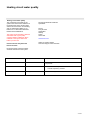
Heating circuit water quality
Heating circuit water quality
The composition and quality of the
system water have a direct influence on
the performance of the whole system
and the life of the boiler. On first filling,
and any subsequent refilling, a pH
balance of 7-8 should be maintained.
Please see the table below
The system must be flushed, cleansed
and treated with a good quality
corrosion inhibitor suitable for all the
materials in the system before the
boiler is put into use.
Failure to do this may affect the
boilers warranty.
Recommended Water treatment
Specialists:
Fernox
Forsyth Road
Sheerwater
Woking
Surrey
GU21 5RZ
www.fernox.com
Office Tel: 01483 793200
Technical Support: 0870 870 0362
No Chemical anti-corrosion medium
should be introduced to the system
Criterion
Appropriate Value
Effect of Deviation
PH - balance
7-8
Danger of corrosion for boiler and system
components.
Hardness
14 dH
-
Chloride content
150 mg/l
Corrosion of alloyed materials
Raised calcium deposits
Low life expectancy of boiler
4 of 49
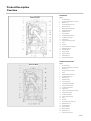
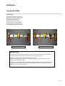
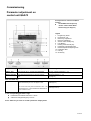
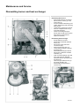
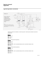
Product Description
Overview
EURON HG
Legend
1
Air intake openings
2
Concentric air intake/flue gas connection
3
Manual air vent
4
Flue gas discharge / Flue hood
5
Burner Door / Burner
6
Stainless steel heat exchanger
7
Condensate drain hose
8
NTC Return sensor
9
NTC Flow Sensor
10
Condensate discharge Siphon
11
Low water pressure switch
12
Supply air hose
13
Heating system pressure gauge
14
Pump
15
Gas valve
16
Premix air/gas burner supply tube
17
Modulating burner fan
18
Ionisation electrode
19
Ignition electrode
20
Ignition transformer
21
STB flue gas 85 °C
22
Air/flue gas sampling points
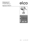
EURON 30 HSG Combi
Euron 30 HSG
Legend
1
Air intake openings
2
Concentric air intake/flue gas connection
3
Manual air vent
4
Flue gas discharge connection
5
Burner
6
Stainless steel heat exchanger
7
Condensation drain hose
8
NTC Flow sensor
9
NTC Return sensor
10
3 way diverter valve
11
Condensate discharge Siphon
12
NTC domestic water sensor
13
Low water pressure switch
14
Supply air hose
15
Domestic hot water plate heat exchanger
16
Cold water inlet with filter
17
Hot water flow regulator
18
Heating system manometer
19
Pump
20
Gas valve
21
Premix air/gas burner supply tube
22
Modulating burner fan
23
Ionisation electrode
24
Ignition electrode
25
Ignition transformer
26
STB flue gas 85 °C
27
Air/flue gas sampling point
5 of 49
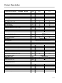
Product Description
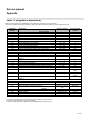
Technical Data – System Boiler
Units
HG 24
HG 30
Nominal Heat Output at 80° / 60° C
kW
5,8-22,8
6,9-28,1
Nominal Heat Output at 50° / 30° C
kW
6,1-23,6
7,2-29,2
Nominal Heat Input
kW
6,0-23,0
7,1-28,5
Normal supply level 75° / 60°C
107,2
107,1
108,6
108,5
Standby loss TK = 70°C
%
%
%
0,1
0,1
Max. output pressure of Fan
Pa
110
90
L
1,8
2.5
bar
3.0
3.0
Normal supply level 40° / 30°C
Water content
Max. water pressure
Max. flow temperature
°C
82
82
ca. l/h
1,58
2,95
Natural Gas G20
m3/h
2,43
3,01
Liquid Propane Gas LPG / G31
kg/h
1,81
2,25
20 Natural Gas
50 LPG
18 / 25 Natural Gas
50 LPG
12,47
Condensate quantity at 40° / 30°C (22 kW)
Gas Flow rate:
Gas flow pressure: Nominal
mbar
Gas flow pressure: min / max.
mbar
Flue gas mass flow rate with Natural gas
g/s
10,19
Max Flue gas temperature
°C
74
Gas category
71
112H3B/P; 112E3P
Flue Classification
(B23 C13x C33x C43x C53x C63x C83x)
Electrical protection rating
IPX4D
NOx
Class 5
Ionisation min
uA
1
1
Air/flue gas hose
DN
80/125
80/125
Heating Flow / Return
mm
22
22
Gas connection
DN
3/4"
3/4"
Condensate hose connection
mm
28
28
pH balance - condensate
pH
3,2
3,2
Electrical Power consumption 230 V / VAC
W
129
129
Connections:
CE - Identification number
Width x height x depth
Weight ca.
Noise level Min./Max. load
0085BP0033
mm
kg
450 x 750 x 378
35
dB (A)
37
36 -44
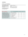
Product variables in calculating installation costs
according to DIN V4701-10:
Rated heat capacity
Q„ (kW)
22,8
28,1
Efficiency at rated heat capacity
hio„% (%)
98,4
97,8
Part load efficiency
h3o% (%)
107,8
107,4
Return temp, on measurement of 30% part load efficiency
T 30% (C)
30
30
Standby heat loss
q B.70 (%)
2,6
2,2
W
129
129
Electrical Consumption Max
6 of 49
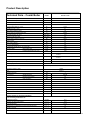
Product Description
Technical Data – Combi Boiler
Units
HSG 30 Combi
Nominal Heat Output at 80° / 60° C
kW
6,9-28,1
Nominal Heat Output at 50° / 30° C
kW
7,2-29,2
Nominal Heat Input
kW
7,1-28,5
Normal supply level 75° / 60°C
107,1
Standby loss TK = 70°C
%
%
%
Max. output pressure of Fan
Pa
90
Normal supply level 40° / 30°C
Service water temperature max./min.
108,5
0,1
°C
60/35
Hot water quantity AT=40°C
l/min./60°C
10,0
Minimum HWS Flow rate
l/min./60°C
2,5
bar
6/0,8
I
2,5
bar
3.0
Service water pressure max./min.
Water content
max. water pressure
max. flow temperature
°C
82
ca. l/h
2,95
Natural Gas G20
m3/h
3,01
Liquid Propane Gas LPG / G31
Kg/h
2,25
Condensate quantity at 40° / 30°C (22 kW)
Gas Flow Rate:
Gas flow pressure norm
mbar
Gas flow pressure min./max.
mbar
20 Natural Gas
50 LPG
18 / 25 Natural Gas
50 LPG
Flue gas mass flow rate with Natural gas
g/s
12,47
Max Flue gas temperature
°C
71
Gas category
112H3B/P; 112E3P
Flue Classification
(B23 C13x C33x C43x C53x C63x C83x)
Electrical protection rating
IPX4D
NOx
Class 5
Ionisation flow min.
uA
1
Air/flue gas hose
DN
80/125
Heating Flow / Return
mm
22
Gas connection
DN
3/4"
Condensate hose connection
mm
28
pH balance - Condensate
pH
3,2
Electrical Power consumption 230 V / VAC
W
Connections:
CE - identification number
Width x Height x Depth
129
0085BP0033
mm
450 x 750 x 378
kg
37
dB (A)
36 – 44
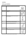
Rated heat capacity
Q„ (kW)
28,1
Efficiency at rated heat capacity
hioo% (%)
97,8
Part load efficiency
h3o% (%)
107,4
Return temp.on measurement of 30% part load efficiency
T 30% (C)
30
Standby heat loss
q B.70 (%)
2,2
W
129
Weight ca.
Noise level Min./Max. load
Product variables in calculating Installation
costs according to DIN V4701-10:
Electrical Consumption max
7 of 49
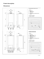
Product description
Dimensions
EURON24HG EURON 30 HG
Legend
A Flow 3/4"
C Gas inlet 3/4"
E Return 3/4"
G Condensation discharge 28 mm
H Siphon
(*) Water connection
(**) Gas connection
EURON 24 HSG Combi
EURON 30 HSG Combi
Legend
A Flow 3/4"
B Hot water outlet 1/2"
C Gas inlet 3/4"
D Cold water inlet1/2"
E Return 3/4"
G Condensation discharge 28 mm
H Siphon
(*) Water connection
(**) Gas connection
8 of 49
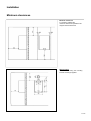
Installation
Minimum clearances
Minimum clearances
For servicing of Boiler the
minimum clearances specified in the
diagram must be observed.
Wall mounting
Fix to the wall using the mounting
bracket and fixings supplied.
9 of 49
Installation
Connection Kits
Connection Kit.
Each boiler comes with a connection
kit for gas, flow and return connections
on the system boiler and gas, flow,
return and Hot water service
connections for the Combi boiler.
These kits are there to aid installation
and remove the need for the installer
to provide isolation valves for the boiler
System Boiler Connection Kit
Combi Boiler Connection Kit
Important Note:
The Gas Isolation Valve, that is included as part of the connection bracket assembly (for Boiler
versions), has a “fire safety feature” and is a thermally closing type device.
The slam shut action of the valve is activated at 100ºC +/- 5K.
Installers should therefore avoid the use of soldered fittings in the gas line which are in close
proximity to the gas isolation valve.
If a fault occurs that indicates that no gas is able to pass through an isolation valve, then it should be
suspected that the thermal shut-off feature has been triggered. There is no possibility to reset a
triggered valve and it must be replaced.
10 of 49
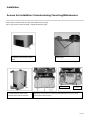
Installation
Access for Installation /Commissioning/ Servicing/Maintenence
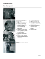
Access to the Boiler is as follows:
Ensure boiler is switched off at the mains and Isolated from gas supply
Then to gain access to inside the boiler, complete the following steps:
1
1
Remove the 4 screws (1) from the
underside of the housing (2 either
side)
2
Open the Release clips on top of the
boiler Casing
240v Connections
3
Pull the Boiler casing towards you.
You will now have acces to the
internal components of the boiler
Low Voltage
Connections
Hinge forward the Control panel (4) for access to the rear of the controller
and wiring. Removing the 5 screws (5) will enable the rear cover (6) to be
removed for access to wiring.
11 of 49
Installation
Connections
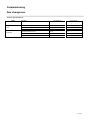
Gas connection
The Boiler is designed to belong to
the following categories for the use of
gas types.
Country
Categories
GB
II2H3P
II2H3B/P
Please check the Boiler name plate and
packaging to ensure that it is correct for
UK Operation and that the gas category
corresponds to one of the appropriate for
the UK.
The gas inlet must be manufactured and
measured according to the relevant
specific country regulations as well as the
maximum output of the equipment; check
also the correct calculation and
connection of the stop valve.
Water connection
All connections for water and gas are
as per the illustration on page 8.
Ensure that the cold water main
pressure does not exceed 6 bar. If > 6
bar then a pressure limiter device must
be fitted.
The minimum pressure needed by the
appropriate devices for processing of
hot service water is about 0.2 bar.
Before installation, the gas line should be
thoroughly cleaned, so that any residue
does not impair the functional efficiency
of the heating appliance.
On sizing the pipes and the heating
element of the Boiler, the residual
head pressure must be considered
depending on the required flow rate as
per the pump circulation curve (see
page 14)
Also ensure that the boiler is for the
correct type of gas to be used i.e. Natural
Gas or LPG (check the name plate in the
interior of the appliance).
With Combi Boiler (type HSG) flow
limiters are built into the water switch.
This ensures a constant flow of service
water
Check the required gas pressure for
either natural gas or LPG.
(EURON 24 HSG = 8 Litre/Minute
EURON 30 HSG = 10 Litre/Minute).
Underfloor heating
For underfloor heating, attach a
suitable safety thermostat to the
supply. (see page 15)
Note: High flow temperature leads to
an operating lockout of the Boiler both
in DHW and heating operation:
The error code "110" appears on the
display. Operation is resumed by
pressing RESET (6) key (see page 22),
after the flow temperature has
dropped.
12 of 49
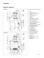
Installation
Hydraulic diagrams
EURON HG
EURON HG/HSG
Legend
1
2
3
4
5
6
14
15
16
17
18
19
20
21
22
23
24
25
Manual bleed valve
Stainless steel heat exchanger
Burner
Mixing channel air/gas
Modulating Fan
Venturi
Gas valve
NTC-Appliance supply sensor
Motor of 3-way valve (Combi)
3-way valve (Combi)
Minimum pressure switch
NTC-Service water sensor (Combi)
Service water plate heat
exchanger (Combi)
Service water flow control (Combi)
Cold water filter (Combi)
Automatic heating bypass
3 bar safety valve
Pressure Gauge
Circulation pump
Automatic bleed valve
Condensate syphon
NTC-appliance return sensor
Flue Gas Collection Hood
Expansion tank (optional)
Flue Gas STB
A
B
C
D
E
Flow 3/4"
Hot water outlet 1/2" (Combi)
Gas intake 3/4"
Cold water intake1/2" (Combi)
Return 3/4"
7
8
9
10
11
12
13
EURON HSG
13 of 49
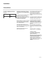
Installation
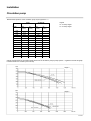
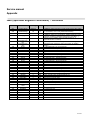
Circulation pump
Residual head pressure of the circulation pump at pump speed 2 + 3
24 HG
Flowrate
V3
(mbar)
30 HSG/HG
V2
(mbar)
V3
(mbar)
V2
(mbar)
Legend
V2 2. Pump stages
V3 3. Pump stages
1300
1200
127,5
1100
162,5
1000
221
900
280
83
252
800
325
142,5
308
102
700
373,5
207
361
165
600
419,5
269
409
231
500
459,5
320
463
287
400
491,5
365
503
343
300
522
408,5
548
394
200
547
440
561
440
100
568
470
588
467
0
584
494
601
491
119
190
Graphic representation of the residual head pressure of the circulation pump at pump speed 2 + 3 (please note that this graph
includes models not covered by this manual)
Stage 3
Stage 2
14 of 49
Installation
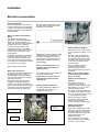
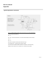
Electrical connections
General Information
Electrical installation and connection
must be carried out by an authorised
installer in accordance with applicable
National Standards, Local Standards
and Regulations.
Mains connection and Customer
wiring
The appliance is designed for
permanent connection using cables
NYM 3x1.5 mm2 or H05W-F 3 x 1
mm2. The connection cable should not
be larger than 8 mm in diameter.
Connect the mains wiring to the
respective terminals, on the Boiler
Terminal strip, in the 240V section at
the rear of the control panel. (See
picture below)
A suitable mains isolator switch must
be fitted in the power supply, to the
boiler, and sited in the boiler room.
This can be used to switch off power
to the boiler for maintenance purposes
or in the event of a problem.
When connecting the boiler, ensure
the earth cable (yellow/green), which
is longer than the supply wires (see
illustration) is connected.
Multiple plug sockets, extension cable
and adapter are not appropriate. For
earthing of the appliance under no
circumstances use the piping of the
water supply installation, heating or
gas installation.
Please note the appliance is not
protected against damage from
lightning strikes.
Mains voltage: 230 V, 50 Hz
Mains cable Connection
All external connection cables should
be stripped to a max. 30 mm. All
external Cables entering the Boiler
must be firmly clamped in the Cable
grip after connection
The length of the cables must be
designed accordingly. Additional
cables (e.g. for system integrations),
which are attached to the terminal strip
in the boiler, must be secured along
with mains lead via the Cable grip.
If the mains fuses are to be changed,
use 2A Quick Blow fuses.
Note before any connections are
made below the boiler must be
switched Off.
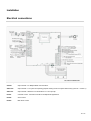
Remote Operation (Volt Free)
A volt free enable to the Boiler for a
Thermostat, Time switch etc, is
possible via X10-02 (2)
Cable Grip
Connection for
Underfloor limit
thermostat
240V Connection.
1st TwoTerminals
Earth Block
240v Mains Power Connection
Remote Operation (QAA73)
Connection (1) for a QAA73 must
be via a cable with at least. 2 x 0,5
mm2.
The "Bus" cable of the QAA73
(20-30 V) must be installed and
run separately from the 230 V/50
Hz cables. The QAA73 connects
to the X10-01 connector using
screened cable.
Note: If the QAA 73 remote
control is being used, the
thermostat bridge must be
disconnected from the X10-02 (2)
connection.
Note: Only one type of Boiler
enable can be used via either
X10-01 or X10-02
Ambient / External Sensor
(QAC34)
Connect the Outside Air
Temperature sensor (3), if
required, using a Screened Cable
2
with at least 2 x 0,5 mm , with a
maximum length of 50m.
The sensor should be positioned
on a North Facing Wall at a height
of 2 –2.5 m above the floor. Under
no circumstances must it be
directly exposed to sunlight.
Connect the ambient/external
sensor to the X10-06 (3)
connector (using screened cable).
Safety Thermostat for
Underfloor Heating
Remove the bridge loop from the
terminals on the right hand side of
the Terminal Block, on the 240v
connection side, and connect the
safety thermostat for the
underfloor heating.
The Connections on the boiler
wiring side will be pre-wired back
to X3-01 on the LMU unit.
15 of 49
Installation
Electrical connections
Controls Options / Accessories
OCI420
Clip in Module - For Multiple Boiler communication.
AGU2.514
Clip in Module – For system incorporating pumped Heating circuit & Pumped HWS Primary (see P46 – scheme 1)
AGU2.511
Clip in Module – BMS Run / Fault Indication & 0 -10v input Clip
RVA47
Cascade Control - Cascade Controller for multiple boiler applications
RVA46
Zone Control
RVA63
Multi Zone Control
16 of 49
Installation
General
Connection of air/flue gas pipes
Flue gas and supply air connection
The EURON is suitable for use as
conventional or balanced Flue. The
flue that is connected must be
removable.
As with all flue systems, it must be
ensured that there is no short circuit /
cross-contamination
between
the
supply air and flue gas.
For flue gas safety the EURON is
fitted with an flue gas temperature
safety limiter (set at 85°C), therefore
this does not need to be provided for
in the installation.
Condensate created in the flue must
also be allowed to drain away freely
with the same considerations as for
the boiler condesate. Local regulations
must
be
observed.
Prior
to
commissioning the siphon in the
EURON must be filled with water .
Connection to air/flue gas routing
For concentric air/flue gas routing only
original MHS accessory parts should
be used.
The combustion air supply must be
ensured. In areas such as in a laundry
or workshop, a hair salon, in areas with
electroplating,printing or metalworking.
In such or similar cases the supply air
must be supplied from a outside the
building.
Condensate connection
3
For every m of natural gas burnt, 0.7
to 1.0 litres of condensate is produced,
as a consequence of the very high
utilisation of energy. This of course
must be discharged from the boiler.
Due to its acidic nature, plastic piping
must be used for draining the
condense. The condensate must be
able to run off freely into a tundish (or
neutralization tank), therefore avoiding
a back-up of condensate into the
boiler. Please Refer to BS6798:2000
for guidance.
(See picture to right)
Condense
Connection
17 of 49
Installation
Air-flue gas Installation
For the installation of concentric
air/flue gas systems the use of
original accessory parts by MHS is
recommended.
Connection kits for fluing of the air/
flue gas are supplied separately from
the appliance depending on the
various installation options.
This boiler comes ready for
connection to a concentric air/flue gas
system.
The flue connection to the boiler can
be either using 80/125mm concentric
flue or via double pipe 80/80mm flue.
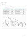
18 of 49
Installation
Air/flue gas Installation
Combustion Air from the Boiler Room, Ø 80mm PPS
B23
Open Flue Appliance – Air Supply fgrom the room – Flue Gas discharge via
roof.
Room Sealed Appliance, Ø 80/125mm PPS / Alu
C13
Room sealed appliance – Connected to Concentric supply / flue discharge
through a wall
C33
Roome Sealed appliance – connected to concentric air supply / flue
discharge through the roof
C43
Room Sealed appliances, connected in cascade, connected to a common U
shaped concentric supply / flue discharge at the appliance
C53
Room sealed appliance, connected to a separate air supply and flue
discharge pipe, opening into different pressure areas.
C63
Room sealed appliance, sold without related connecting and/or discharge
fittings.
C83
Room sealed appliances in cascade, connected to separate air supplies
but common flue discharge through the roof.
Note: For Flue Gas Termination Guidance please refer to the diagram on page 44
19 of 49
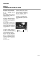
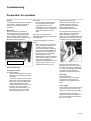
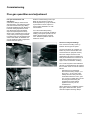
Commissioning
Preparation for operation
General
To ensure the safe and correct operation
of the boiler, commissioning must be
carried out by a suitably qualified
specialist.
Monitoring
Ensure condensate connection is
connected using the condense drain
hose supplied or using plastic piping.
Ensure that the Condense outlet is
piped to a suitable drain. Please refer to
BS6798 for ultimate guidance
Condense Connection
First commissioning
Fill hydraulic circuits
Proceed as follows:
Open the boiler bleed valve and the
valve above the stainless steel heat
exchanger.
Loosen the closure of the automatic
bleed valve on the circulation pump.
Slowly open the system filling point
and shut the bleed valve on the
stainless steel heat exchanger, and
the boiler, as soon as water is
evident. Shut the filler valve, once
the pressure shown on the water
pressure gauge reaches 1.0 bar.
Ensure that:
The the automatic bleed valve on
the circulation pump is opened.
The boiler pressure, on the
manometer is 1 bar. The gas valve
is completely shut off. The electrical
connection has been correctly
made.
Ensure in every case, that the
green/yellow earth wire is connected to
a suitable earth.
To bleed the appliance, proceed as
follows:
Switch on boiler (10). This sets the
pump of the heating appliance in
operation and there are three
consecutive attempts to ignite the
burner. After the third attempt the
electronics lock the appliance, as
the gas supply is cut; the display
shows the readout "133".
Allow the pump to work until all the
air has left the appliance. Vent the
boiler. Check the appliance
pressure and refill with water in the
case of a drop in pressure, until
pressure again reaches 1 bar.
Check the flue gas system.
Ensure that any necessary room
ventilation openings are open.
Ensure the boiler condensation
siphon is filled with water.
(See illustration below centre).
If the appliance is unused for a long
period, the siphon must be filled
before switching on again. It is
dangerous not to refill the siphon with
water, as this can cause the flue gas
to escape from the condense drain.
Open the gas tap and check the
tightness of all connections. Unlock
the boiler by pressing the Reset key
"6". The burner will ignite. Should this
not happen, repeat the above
procedure, until the burner ignites.
Gas supply
Proceed as follows:
Ensure that the type of gas used
corresponds to the type of gas
indicated on the nameplate of the
boiler.
Power supply
Ensure that the voltage and frequency
of the power supply conform to the
data on the name plate of the boiler.
Ensure that the live and neutral
connections have been made and to
the correct terminals. Check that the
earth is connected.
20 of 49
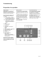
Commissioning
Preparation for operation
Legend
1 Display
2 LED (green) Burner operation
3 LED (red) Alarm appliance
lock
4 LED (green) flow temperature
readout on display
5 LED (green) operating
phase/diagnosis of Boiler
6 Reset Button
7 Display adjustment Button
8 Flue cleaner function Button
9 Summer/winter/automatic
operation Button
10 Power on/off
11 Hot water temperature
Adjustment
12 Heating flow temperature
Adjustment
13 LED illuminates winter
operation
14 LED (green) automatic Boiler
operation
Commissioning
Switch on the POWER (10) – 0 = Off;
1 = On 1. The display will illuminate,
then after a few seconds the heating
appliance is ready to operate.
Winter and summer operation
Use MODE (9) button to change
changed between winter and summer
operation and vice versa. When LED
(13) is illuminated the boiler is on
winter operation.
If an outside air temperature sensor is
fitted to the boiler, the changeover
from winter operation (heating and hot
service water) to summer operation
(only hot service water) can occur
automatically, if the outside
temperature measured is higher than
20 °C.
This can be achieved by pressing the
MODE Button (9), until the LED AUTO
(14) is illuminated. To deactivate the
automatic changeover press the
MODE key, until the LED AUTO (14)
is no longer illuminated.
Note:
Adjustments made to the heating
temperature and the service water
temperatures remain unchanged after
a power cut.
Adjustment of the heating
temperature and service water
temperature is undertaken using a
QAA73. (see page 23)
21 of 49
Commissioning
Preparation for operation
Display readout
Whilst the Boiler is in operation the
digital display (1) shows the flow
temperature of the Boiler whilst at the
same time LED (4) is illuminated.
By pressing SELECT button (7) the
following options are displayed in
succession:
LED (4) Flashing – Display
shows Hot Water Temperature
No readout (Display shows -.-)
LED (5) Lit Shows operational
Status of Boiler – LED‟s (4)
and (5) are off - Sequence
Status of the boiler shown as
follows:
0
1
2
3
4
5
6
10
11
20
22
99
Boiler Lock Out
If a malfunction occurs the Boiler will
Lock Out for safety reasons, the fault
is displayed by illumination of the LED
(3).
To restart the boiler: press RESET (6)
for approx 2 seconds. If the lock out
reoccurs, then check the gas supply to
the boiler, and/or the Flow / Return
Water isolation valves are open and
the boiler is above or below pressure
limitations.
If the lockout persists, contact MHS
Service department.
Use of flue cleaner key
The flue cleaner key (8) is only used
by a qualified specialist responsible
for maintenance, to undertake
calibration and carry out all checks
necessary for the correct operation of
the appliance. If the key is
inadvertently pressed, do not press
any other keys, but switch off the
appliance by means of adjusting knob
(10) and then switch on again.
Pause
No Heat Demand
Fan Ramp Up
Pre Purge
Changeover of Pre Purge to
ignition
Ignition
Flame Stabilisation / Rectification
Heating operation mode
Service water mode
Venting
Fan Run Down
Boiler Locked Out for
safety reasons
Locking code or information
relating to operating conditions of
heating appliance
Pressing Key (7) again will again
show the service water temperature
reading on the display. After a few
minutes the display returns to boiler
temperature.
22 of 49
Commissioning
Parameter adjustment on
control unit QAA73
Prerequisites for control unit QAA73
function
The EURON must be put into
"winter" mode viathe ‘Mode’
function key (see Page 21)
Legend
1 Program key „Down‟
2 Program key „Up‟
3 Minus Key Adjustment
4 Plus Key Adjustment
5 Service water standby Key
6 LCD Display
7 Heating circuit standby key
8 Parameter Code appears here
9 Rated temperature adjusting knob
10 Parameter value
11 Info Key
12 On/Off key
Application level
Key operation
Parameter range
QAA73 - User
Press program key 2 – Scroll through Parameters
End User / Operator Parameter 1 – 50
(see Page 40)
QAA73 - Engineer
Press and Hold program keys 1 and 2 for approx 5
secs.
Specialist Parameter 51 – 98
(see page 41)
Back via "INFO" key
LMU
Key operation in this order:
Press and Hold Keys 4 and 1 for approx 5 secs.
Engineer LMU Parameter 516 – 727
(See Page 42)
Then for the next level (whilst in Parameters 516 – 727) Specialist Engineer Parameter 501 – 755
Keep program keys 1 and 2 pressed simultaneously for (See Page 43 & 44)
approx a further 5 secs.
In the corresponding parameter range
Parameters are selected using keys 1 and 2
Values are changed using keys 3 and 4
Press "INFO" key to return to normal operational / display mode
23 of 49
Commissioning
Flue gas quantities and adjustment
Flue gas measurement and
adjustment
Combustion settings need to be set
with the boiler in commissioning mode
(via Flue Cleaner button (8)), setting
the boiler at Maximum load / Minimum
load and making adjustments at the
gas valves Max Output and MinM
output as required. (Ref P24 & 25)
When in the commissioning mode the
3-way valve (Combi Only) is diverted
to heating mode, the temperature limit
values of the boiler are disabled and
only the maximum safety temperature
remains activated (Q5°C)
Whilst in commissioning mode to put
Boiler at max output turn Service
Water adjustment (11) fully clockwise,
to put boiler into minm output trun
service water adjustment (11) fully
anti-clockwise
If an HG model boiler (heating
operation only) is used with underfloor
heating, interrupt the operation of the
boiler if the temperature exceeds
45°C. Resume operation after the
boiler has cooled.
Access for Analyser Readings
First unscrew the locking screw (1)
between the flue gas test points.
The test point plugs (E= emission, A=
intake air) can be removed with a 90°
anti-clockwise turn (bayonet closure).
Place the analyser Sensor into the
appropriate Test point for measurment.
Flue gas measurement is carried out in
heat mode. Analyser sensor to go in
approx 75mm for Emission checking.
On a Combi If system load is difficult to
achieve, for example during the summer,
the hot water circuit can also be used as
follows:
With the aid of a screwdriver
disconnect the fixing clamps, 3, of
the motor, 4, of the 3-way valve.
Steady the motor with your hand
meanwhile detach the motor, open
one or more hot water taps to let off
the heat generated during the
measurement of the heating
appliance and carry out the
measurement.
When measuring is completed, shut the
taps again, attach the motor, push it
down and replace the fixing clamps.
24 of 49
Commissioning
Flue gas quantity and adjustment
Maximum output
Flue gas measuring and adjustment
Switch the boiler to commisioning mode,
while keeping flue cleaner key (8)
pressed, until the red LED (3) starts to
flash (double flash). The display shows
alternately the figures 1 and 00. With Hot
Water temperature Adjustment (11)
turned fully clockwise, the boiler is
working in heating mode at 100% output.
i.e. maximum output
Wait until the boiler stabilises and then
check the combustion settings, checking
for C02 value in conjunction with the chart
below.
To adjust the combusution, proceed as
follows:
Remove plastic cap and then
adjust High fire (1) on gas valve
using a flat bladed screw driver:
anticlockwise to increase and
clockwise to decrease the C02
value. Enusre correct settings for
corect fuel type is observed.
Note: Because of the sensitivity of
the adjustment, minimum
adjustments should only be made
Wait a few seconds, until the C02
value has stabilised, if applicable
repeat adjustment.
24 HG
G20 Natural gas H
G31 Propane
30 HSG/HG
C02 [%]
C02 [%]
8,7-9,1
8,8 - 9,2
10,7- 11,1
10,8 - 11,2
The measurement of C02 values must take place with appliance casing fitted.
25 of 49
Commissioning
Flue gas quantity and adjustment
Minimum output
Switch the boiler to commisioning
mode, while keeping flue cleaner key
(8) pressed, until the red LED (3)
starts to flash (double flash). The
display shows alternately the figures 1
and 00. With Hot Water Temperature
Adjustment (11) turned fully
clockwise, the boiler is working in
heating mode at 100% output. i.e.
maximum output
24 HG
G20 Natural gas H
G31 Propane
The boiler needs to be set for
operation at minimum load. Turn the
Hot water temperature adjustment
(11) anticlockwise as far as it will go
(the flow temperature of the boiler and
the figure 0 flash alternately on the
display). From this moment, the boiler
is working at minimum output.
Wait until the boiler stabilises and
then carry out the flue gas
measurement. Check the C02 value
at the same time by means of the
following chart.
30 HSG/HG
C02 [%]
C02 [%]
9,3 -9,7
9,0 - 9,4
10,9 - 11,3
10,8 - 11,2
The measurement of C02 values must take place with appliance casing fitted.
3
If values remain within the limits given
in the chart, no further regulation is
necessary.
After these measures the gas flow rate
on the counter should be checked,
taking into account the specifications
contained in the table of technical
data.
If the checks are completed, the
heating appliance must be re-set
manually to normal operation.
For this, keep the flue cleaner key
(8) pressed until the red LED (3)
goes out
If the measured values differ from the
values stated, proceed as follows:
(Numbers in the following text relate to
pictures above)
Remove the cap (2) using a
Torque T-40 bit then adjust the
Low Fire adjustment (3) on the gas
using the same T-40 bit: clockwise
to increase and anticlockwise to
decrease the C02 value of the
reading (because of the sensitivity
of the screw, minimum rotations
are sufficient)
After measuring, check again the
C02 values at High Fire. If High
fire requires any readjustment
also check and readjust Low Fire
as required.
Note: Because of the sensitivity of the
adjustment, minimum adjustments
should only be made, wait a few
seconds, until the C02 value has
stabilised, then if applicable repeat
adjustment.
26 of 49
Commissioning
Flue gas quantities and adjustment
Setting the Boiler for maximum heat
output (%)
The maximum heat output can be set
between the highest and lowest values
appropriate for the appliance or application.
The Boilers are preset in the factory at
100%.
The following steps can be followed to adjust
the output, set the appliance's operation at
the highest output
Press the Flue Cleaner Key (8), until the red
LED (3) starts to flash (double flash)
The display will now alternate between the
flow temperature of the boiler followed by the
figure 1 and then figure 00.
%
Using knob (11), service water temperature
adjustment, the maximum heat output, as a
percentage, can now be set to the required
value (see graph).
To store the adjustment, keep key (8)
pressed until the red LED (3) goes out.
Via the Parameter "d6" the the maximum
RPM of the fan for this setting in heating
operation can be shown (ref p29)
(Please note that this graph includes models not covered by this manual)
27 of 49
Commissioning
Safety check of heating appliance
Monitoring of the safety device
of the heating appliance
Protection system of heating
appliance
Checking the safety devices of the
boiler can be carried out using the
Flue Cleaner Key (8).
The boiler is protected from operating
faults by internal monitors in the
microprocessor circuit board, which
when necessary lock the appliance for
safety reasons. In the case of an
appliance being locked, a code is
shown on the display which gives the
type of locking and its cause. Two
types of locking can occur:
Press and hold the Flue Cleaner Key
(8) until the red LED (3) light is
illuminated then release immeadiatly.
Note: If the button is pressed for too
long i.e until the Red LED flashes with
a double flash then the boiler has
been put into Commissioning mode.
You will then need to reset and start
again.
Once in this mode the LED (3) will
flash and display will alternately flash
between "SF" and the boiler flow
temperature.
The boiler is now working at maximum
output in heating mode, and will
continue to do so until the safety
devices of the boiler are activated.
(On exceeding the temperature limit,
the appliance locks, the red LED (3)
flashes continually and the display
shows safety code 111.)
To resume operation, after cooling of
the appliance press RESET (6) key.
Safety Shut-Off
This type of fault is "temporary",
i.e. the fault is automatically
corrected, as soon as its cause is
corrected. Thereupon the
appliance switches itself on again
and resumes its normal operation.
While the appliance is in safety
stop, you can try to set it going
again by switching off and then on
again.
If safety switch-off occurs
repeatedly, please contact MHS
Service / Technical Support.
Locking
This type of fault is "Permanent",
the heating appliance can be reset
by pressing Key (6).
There follows a list with possible
operating messages and the
corresponding codes shown on the
display.
28 of 49
Commissioning
Parameters
Reading parameters only
Reading of the boiler parameters is
done by means of the SELECT (7)
key
•
•
•
•
•
•
•
•
Keep the SELECT key (7)
pressed until “[ ]" appears on the
display (about 5 secs)
release the key.
Press the key again until "bO"
appears on the display (approx 5
secs.)
Release the key.
Now each time the key is
pressed, the display shows the
parameters shown on the right.
When finished Keep the key
pressed tillfor approx 4 secs, until
the display shows "-.-."
Release the key.
The display now reverts to the
standard readout (heating flow
temperature).
Note: The display reverts to the
normal readout if no buttons are
pressed or adjustments made for
approx 8 minutes.
The only accessible reading
parameters are the following:
A0
Current fault readouts
A1
Boiler flow temperature reading
(°C)
A2
Service water temperature
reading(°C)
A3
not used
A4
Reading for operating phase of
boiler.
b0
Internal code in case of fault.
b1
Boiler return temperature reading
(°C)
b3
Reading of flue gas sensor
temperature
b4
Reading of outside temperature
(°C)
b5
not used
b6
not used
b7
Temperatuere of circuit of second
zone (°C)
b8
not used
b9
not used
C1
Reading for ionisation current (u.)
C2
Reading for ventilator revolutions
figure (thousands and hundreds)
C3 PWM fan (%)
C4
Reading of relative heating
appliance heat output (%)
C5
not used
C6
not used
C7
not used
d1
Setpoint, calculated according to
type of operation, service water
or heating operation.
d2
Value of calculated heating flow
temperatures (°C)
d3
Readout of set room temperature
value (°C) If no external/ambient
sensor is available, the value is
set at 20 °C
d4
Adjustment of value of service
water temperature (°C)
d5
not used
d6
Maximum fan speed in heating
operation (thousands and
hundreds)
d7
not used
d8
not used
29 of 49
Commissioning
Gas changeover
Changeover from natural gas to
liquid gas (LPG)
1. Disconnect the boiler from the
mains.
2. Shut the gas Isolation valve
3. Removing the boiler casing
4. Dismantle the mixing channel by
loosening the 3 screws (1).
Disconnect the electrical
Connections of the fan (3) and the
gas valve (4). Remove the air
intake hose (5).
5. Separate the gas valve from the
venturi by removing the 4 screws.
6. Install the gas injector (contained in
changeover kit), as shown in the
preceding illustrations.
7. Reinstall the ventilator/venturi
gauge/gas valve group in the
boiler.
8. Install the air screen (see chart
page 31) for liquid gas (contained
in changeover kit) on the left of the
heat exchanger.
9.
10.
11.
12.
13.
14.
15.
Connect the appliance to the
mains.
Open the gas isolation valve
Put the appliance into operation
according to the information in the
Instruction manual.
Check the gas seals.
Replace the front panel of the
combustion chamber.
Carry out a combustion analysis
and a calibration of the maximum
heat load.
Replace gas shield.
The air screen is on the left of the heat
exchanger.
30 of 49
Commissioning
Gas changeover
Chart for gas changeover
Output
24 HG
30 HSG/HG
Gas type
Screen for gas
Screen for air
G20/G25 Natural gas H/LL
None
None
G31 /Propane
0 4.6 mm
53/8mm
G20/G25 Natural gas H/LL
None
None
G31 /Propane
0 4.6 mm
57/12,5mm
31 of 49
Commissioning
Chart for gas changeover
Gas changeover
G20
Natural
Gas
H
o
I
CM
Lower Wobbe index
(15 °C, 1013 mbar) (MJ/m3)
Consumption
(15 °C, 1013 mbar)
(Natural gas = m3/h) (Liquid gas = kg/h)
45,67
I
00
CO
I
—
o
I iCM
O
CO
I
—
o
Io
37,38
G30/G31
Butane/
Propane
80,58
G31
Propane
70,69
1,22
1,41
0,91
0,91
0,89
min.
0,32
0,32
0,37
0,24
0,24
0,23
0,14
0,14
0,16
0,11
0,11
0,10
45,67
37,38
80,58
70,69
max.
1,90
1,90
2,21
1,42
1,42
1,40
min.
0,49
0,49
0,57
0,36
0,36
0,36
0,22
0,22
0,26
0,17
0,17
0,16
Gas consumption after 10 Min.
(at 70% of max. output)
(Natural gas = m3/h) (Liquid gas = kg/h)
O
G30
Butane
1,22
Lower Wobbe index
(15 °C, 1013 mbar) (MJ/m3)
Consumption
(15 °C, 1013 mbar)
(Natural gas = m3/h) (Liquid gas = kg/h)
G25
Natural
Gas
LL
max.
Gas consumption after 10 Min.
(at 70% of max. output)
(Natural gas = m3/h) (Liquid gas = kg/h)
o
G20/G25
Natural
Gas
H/LL
Lower Wobbe index
(15 °C, 1013 mbar) (MJ/m3)
45,67
37,38
80,58
70,69
max.
2,43
2,43
2,83
1,81
1,81
1,79
min.
0,63
0,63
0,74
0,47
0,47
0,47
Gas consumption after 10 Min.
(at 70% of max. output)
0,28
0,28
0,33
0,21
0,21
0,21
Lower Wobbe index
(15 °C, 1013 mbar) (MJ/m3)
45,7
45,7
37,38
80,58
80,58
70,69
max.
3,01
3,01
3,50
2,25
2,25
2,21
min.
0,75
0,75
0,87
0,56
0,56
0,55
0,35
0,35
0,41
0,26
0,26
0,26
Consumption
(15 °C, 1013 mbar)
(Natural gas = m3/h) (Liquid gas = kg/h)
Consumption
(15 °C, 1013 mbar)
(Natural gas = m3/h) (Liquid gas = kg/h)
CO
Gas consumption after 10 Min.
(at70% of max. output
(Natural gas = m3/h) (Liquid gas = kg/h)
32 of 49
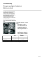
Service and maintenance
Monitoring and checking
Maintenance is fundamentally
essential for the safe and correct
operation and long life of the boiler.
It is recommended, that
combustion analysis be carried out
at regular intervals, in order to
monitor the load and pollutant
emissions of the boiler.
If the boiler is decommissioned in an
area where the room temperature in
winter can fall below 0°C, it is advised
to mix the water of the boiler with
antifreeze, to avoid frequent
evacuation.
Check carefully when using antifreeze
if this is suitable for stainless steel,
from which the inner part of the
heating appliance is made.
The manufacturer is not liable for
damage to the appliance or the
equipment caused by use of
unsuitable antifreeze or additives
Before starting servicing
Before performing any servicing and
cleaning, the appliance must be
disconnected from the mains.
Gas supply isolator and Water
Isolation valves closed for both
heating and Hot water
33 of 49
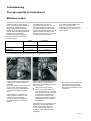
Service and maintenance
Monitoring and checking
General remarks
At least once a year the appliance
should undergo the following
monitoring:
1. Check seals of water pipes and if
applicable replace.
2. Check seals of gas pipes and if
applicable replace as required.
3. Visual check of condition of all
boiler components.
4. Visual check of burner.
5. Cleaning of main heat exchanger
6. Check functional efficiency of
safety system:
i.e. Temperature protection.
7. Check functional efficiency of gas
feed safety system:
Gas and flame failure
protection (ionisation)
8. For Combi Boiler monitoring of
service water production efficiency
(checking through flow and
temperature).
9. Checking general functional
efficiency of boiler.
10. Remove any oxidization on the
electrode with the aid of an emery
cloth.
11. Check correct positioning / spark
gaps of the ignition and ionisation
electrodes as per the adjacent
picture.
12. Check the combustion fan blades
for debris build up. Remove any
debris with a soft bristle brush or
compressed air.
Cleaning of stainless steel heat
exchangers
For Cleaning the interior/dry side of the
heat exchanger coils, the burner / burner
door assembly must be removed.
For cleaning you may use water, a
cleaning agent (citric acid*) and use a
non-metal brush. Afterwards flush with
water.
Note: Never Clean the Burner itself
Cleaning of the Siphon
To gain access to the siphon, unscrew
the Condense collecting glass clockwise,
which is on the bottom left of the
underside of the boiler. Allow water to
drain out safely. Pour 2 litres of clean tap
water into the heat exchanger and allow
to drain safely through to the cleaning
point.
Refit the Condense Collecting Glass and
poor a further 2 litres of clean tap water
into the heat exchanger to ensure the
siphon is full of water.
Function checking
After completing the maintenance
work fill the heating circuit with a
pressure of around 1,0 bar and bleed
the appliance of air.
Also fill the service water appliance.
Set the appliance in operation. If
necessary, bleed the heating
appliance again. Check the
adjustments and correct operation
of all operator, calibration and
monitoring elements.
Check that the flue gas connection is
completely sealed with no cross
contamination to the combustion air
and is functioning correctly.
If the appliance has not been used
for a long time, the siphon must be
filled before switching on again.
It is dangerous not to refill the siphon
with water, as in this case flue gas
can escape into the atmosphere.
* Cleaning Granules availble from
MHS Spares Department
34 of 49
Service and Maintenance
Locking
Error Codes
Display
Internal Code (bO)
Cause
91
EEPROM failure
92
Hardware failure of electronic circuit board
110
129
110
422
Locking because of over heating
113
506
Activation of flue gas sensor
133
102
Locking because of gas failure
151
151
Activation of thermostats for underfloor heating
Internal locking of circuit board
97
152
Flame at atart of reset phase
Failure in programming
153
259
Reset Button pressed when boiler not in fault
154
425
Flow temperature rising too rapidly or no circulation
160
83
On ignition necessary fan speed not achieved
160
282
Blocked Fan
161
110
Measured fan speed above upper limit
183
105
Circuit board in programming mode
Display
Internal Code (bO)
20
142
Short circuit in heating supply sensor
20
143
Heating supply sensor circuit open
40
144
Short circuit in heating return sensor
40
145
Heating return sensor circuit open
50
146
Short circuit in service water or water tank sensor
50
147
Service water or tank sensors circuit open
111
141
Flow temperature above temperature limit (90 °C)
119
140
Low Water Pressure
135
84
Quantity of fan revolutions not correct
154
401
Return temperature greater than flow temperature
154
433
At Supply and return too high
Safety cut-off
Cause
35 of 49
Service and Maintenance
Information code
Error Codes
Display
Internal Code (bO)
Cause
10
150
Short circuit in external/ambient sensor
10
151
External/ambient sensor circuit open
61
Remote control or room temperature sensor signal distrubed
62
Connection of an incompatible remote control or time switch
92
Failure of electronic hardware
133
101
Flame attend of safety period not detected
134
98
Extinguishing of flame during operation
180
168
Flue cleaner function active
36 of 49
Maintenance and Service
Removing appliance cover
Bringing appliance into service position
Maintenance, Service and
cleaning must be carried out by
trained and approved Personnel.
This person shall be responsible
for correct implementation of
Mantainence activities.
Prior to maintenance work, the
appliance must be isolated from the
Electrical Mains Supply, Gas
Supply, and Water Flow and Return
connections shut off.
It is recommended that
Maintenance / Service works are
carried out once a year.
See P39
See Page 11 for cover removal
details
37 of 49
Maintenance and Service
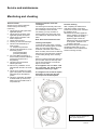
Dismantling burner and heat exchanger
Dismantling Burner Door
•
•
•
•
•
•
Remove all electrical connections
Disconnect the screws (1) of the
mixing tube (2)
Pull out ionisation electrode (4) and
ignition electrode (5) after loosening
fixing screws
Loosen fixing screws (6) on burner
Remove complete burner unit (7)
from heat exchanger
Check surrounding seal (8) of
burner plate as well as the ceramic
fibre seal (9) for damage and
replace if necessary
Dismantling Heat exchanger
•
•
•
•
•
•
•
•
•
•
Empty appliance of water
Disconnect condensate drainage
hoses (10)
Disconnect supply and return
connections (15)
Remove both fixing clips (17)
Loosen fixing screws (11) for heat
exchanger (12)
Detach heat exchanger forwards
Disconnect combustion chamber
insulation (13)
Flush out heat exchanger (12) with
pure water (remove obstinate
impurities with fine synthetic brush
and flush out)
Clean flue gas collection unit (14)
and check all seals (18)
Reassemble all components in
reverse order.
38 of 49
Service and Maintenance
Maintenance, Service and
cleaning must be carried out by
trained and approved Personnel.
This person shall be responsible
for correct implementation of
Mantainence activities.
It is recommended that
Maintenance/Service works should be
carried out once a year. Cleaning of
the heat exchanger coils, as long
there is only minor contamination of
the coils, should be carried out at least
every 2 years.
•
•
•
•
•
•
•
•
•
Measuring and recording of preset
emission values
Switch off heating circuit breaker
and secure against coming on
again, or separate the appliance
on all poles from the mains
Isolate the Gas Supply
Dismantle appliance casing, bring
control panel into service position
Dismantle compressor, gas valve
and burner unit
Disconnect ignition cable. Check
ignition plugs for breaks, moisture
(damp/moist ignition plugs cause
malfunction messages - replace
ignition plugs)
Visual check of burner (if
necessary clean with brush/nylon
brush or vacuum cleaner)
Visual check of Fan and venturi
burner (if necessary clean with
brush/nylon brush or vacuum
cleaner)
•
•
•
•
Disconnect combustion chamber
insulation
Flush out heat exchanger with
pure water (remove obstinate
impurities with fine synthetic
brush and flush out)
Clean siphon and refill with water
before assembly
Check all connections of
condensate-carrying parts for
watertightness. Remove any
leaking condensate or other
dampness
Check fixing screws, replace if
necessary.
•
•
•
•
•
•
The dismantled seals for gas and
water carrying parts should be
replaced with new seals when
reassembling; this applies
especially for O rings on the gas
valve and all burner seals
Reassemble appliance ready for
operation
Open gas pipe and check for
watertightness
Switch on heating circuit breaker
Carry out function monitoring with
emissions measurement
Values according to factory
specifications, readjust if
necessary
39 of 49
Service manual
Appendix
QAA 73 (End User Parameters)
Scroll through Parameters using key 2 (Up Button) – ref Page 22
Parameter
Number
1
2
3
Description
Current Time of Day.
Current Date (Day / Month)
Year
Options / Range
00:00 – 24:00
1 Jan – 31 Dec
2000 - 2094
Recommended
Default
Actual Time.
Actual Date.
Actual Year.
Frost - Day
4 - Reduced
20 - 60ºC
16ºC
10ºC
55ºC
5
6
7
Reduced Room Temperature Set Point.
Frost Protection Set Point (Room)
HWS Target Temperature
10
11
12
13
14
15
16
Heating Zone - Day Selection
Time Switch Heating Zone - First ON
Time Switch Heating Zone - First OFF
Time Switch Heating Zone - Second ON
Time Switch Heating Zone - Second OFF
Time Switch Heating Zone - Third ON
Time Switch Heating Zone - Third OFF
Mo – Su & Week
00:00 – 24:00
00:00 – 24:00
00:00 – 24:00
00:00 – 24:00
00:00 – 24:00
00:00 – 24:00
Day Required
06:00
22:00
--:---:---:---:--
30
31
32
33
34
35
36
DHW Zone – Day Selection
Time Switch Hot Water Zone - First ON
Time Switch Hot Water Zone - First OFF
Time Switch Hot Water Zone - Second ON
Time Switch Hot Water Zone - Second OFF
Time Switch Hot Water Zone - Third ON
Time Switch Hot Water Zone - Third OFF
Mo – Su & Week
00:00 – 24:00
00:00 – 24:00
00:00 – 24:00
00:00 – 24:00
00:00 – 24:00
00:00 – 24:00
Day Required
06:00
22:00
--:---:---:---:--
40
Holiday Start Date
Inactive
41
Holiday End Date
42
Room Temperature Operating Level During Holiday
Period.
1 Jan – 31 Dec
& Inactive
1 Jan – 31 Dec
& Inactive
Frost / Reduced
45
46
47
50
Default Reset of Time Switch Settings
External Summer/Winter Changeover Temperature.
Display Language
Fault Code
YES / NO
8…..30ºC
English…………..
0…..255
NO
Inactive
Frost
English
Review Only
40 of 49
Service manual
Appendix
QAA 73 (Engineer Parameters)
Press and Hold program keys 1 (Down button) and 2 (Up button) for approx 5 secs. Ref Page 22
* Lines are only displayed if the unit is operating in Open Therm Plus mode and if the boiler controller supports its function.
Parameter
Number
Description
74*
75*
76
77
78
79
80*
Service Values
Current Room Temperature Set Point (Heating Zone 1)
Current Room Temperature Set Point (Heating Zone 2)
Outside Air Temperature (Attenuated)
Outside Air Temperature (Composite)
Actual Value of HWS
HWS Flow Rate
Actual Boiler Return Temperature
Actual Flue Gas Temperature
Actual Solar Panel Temperature
Actual solar Storage Tank Temperature
QAA73 Communication Mode (Open Therm Mode)
Heating Zone Temperature Set Points
Compensation Curves Set Point for Time Switch 1
Minimum Boiler Flow Temperature for Time Switch 1
Maximum Boiler Flow Temperature for Time Switch 1
Compensation Slope Parallel Displacement for Time
Switch 1
Build Construction Type
Influence of Room Temperature on Boiler Operation
Pump Switching Differential
Compensation Slope Auto Adaptation
Optimum Start Time Maximum Shift Limitation (Minutes)
Optimum Stop Time Maximum Shift Limitation (Minutes)
Compensation Curves Set Point for Time Switch 2
81*
82*
Minimum Boiler Flow Temperature for Time Switch 2
Maximum Boiler Flow Temperature for Time Switch 2
83*
90*
91
92*
93*
Compensation Slope Parallel Displacement for Time
Switch 2
HWS Set Points
Reduced HWS Set Point
HWS Enable Switching
Anti Legionella Function (Monday Morning 2,5 Hours Max)
Operating mode for HWS (Eco setting)
95
96*
97
98
Operational Lock
Clock Operation
Summer Time Start
Summer Time End
51
52*
53*
54*
55*
56*
57*
58*
59*
61*
62
70
71
72
73
Options / Range
Recommended
Default
4….35
4….35
-50….+50
-50….+50
0….127
0….16
-40….127
-40….500
-40….250
-40….127
Lite / Plus
#
#
#
#
#
#
#
#
#
#
Plus
2.5….40
8….Max
Min….90
-4.5….+4.5
32
8
80
0.0
Heavy / Light
None / HC1
0.5….4.0
Inactive/Active
0….360
0….360
2.5….40
Light
On HC1
0.5
Inactive
100
30
0 (32 if AGU
used)
8
8 (80 if AGU
used)
0.0
8….Max
Min….90
-4.5….+4.5
8….60
TSP DHW..
Off….On
With Eco / Without
Eco
40
TSP DHW
On
Without Eco
Off / On
QAA73 / Boiler
1 Jan…31 Dec
1 Jan …31 Dec
Off
QAA73
25 March
25 Oct
General
For Access to the LMU level: Access QAA73 Engineer Parameters as detailed above
For Access to LMU Parameters (i.e Line 100 upwards)
Press and Hold program keys 1 (Down button) and 2 (Up button) for approx 10 secs
41 of 49
Service manual
Appendix
LMU (Engineer Parameters)
To Access parameters 516 – 727 from QAA73
Press and Hold Keys 4 (+ Button) and 1(Down Button) for approx 5 secs. Ref page 22
Parameter
Name
Setting
Unit
516
THG
25
ºC
520
dTrAbsenk
10
K
532
533
534
535
Sth1
Sth2
DtR1
DtR2
Diagnose
Code
15
8
0
0
K
K
727
Description
Summer / Winter changeover temperature
(30 °C: Summer / Winter changeover disabled/not active)
Drawdown of the room setpoint at timer connection
("dTrAbsenk" = 0: timer works directly off heating demand)
Steepness of heat characteristic curve heating circuit 1
Steepness of heat characteristic curve heating circuit 2
Room setpoint adjustment heating circuit 1
Room setpoint adjustment heating circuit 2
42 of 49
Service manual
Appendix
LMU (Specialist Engineer Parameters)
For Access to the next level (whilst in Parameters 516 – 727)
Keep program keys 1 (Down Button) and 2 (Up Button) pressed simultaneously for approx a further 5 secs. Ref page 22
Parameter
Name
Setting
Unit
504
TkSmax
85
ºC
505
TkS standard
80
ºC
506
TvSmin
20
ºC
507
TvSmax
80
ºC
521
dTkTrNenn
20
K
522
dTkTrMax
25
K
537
NqmodNenn
30
538
NqmodMin
40
%
541
PhzMax
100
%
551
Kon
Hydraulic
System
2
Maximum boiler setpoint temperature (>= "TkSmin" and <= 90
°C) must be at least 3 K less than for "TkMax"
Boiler setpoint at standard outside air temperature
Minimum flow setpoint temperature (>= 20 °C and <=
"TvSmax")
Maximum flow setpoint temperature ( >= TvSmin and <= 90°C)
Delta T Control: flow and return at standard Outside air
Temperature (>= 2,5 K and <= maximum "dTkTrMax")
Delta-T-control: maximum differential of the supply/return
temperature at standard Ouside Air temperature
Speed level of boiler pump in design point of heating installation
("NqmodNenn" <= "QmodDrehzStufen")
Minimum pump speed permitted for the heating installation
Maximum modulation rate in heating mode (>= "LmodTL" and
<= "LmodVL")
Constant for rapid power fluctuation without ambient effect
6
Hydraulic system adjustment
553
KonfigHks
553
555
KonfigRg1
0010000
558
KonfigRg4
1000000
561
596
605
606
KonfigRg7
ZeitAufZu
LPBAdrGerNr
LPBAdrSegNr
0001000
135
1
0
610
LmodVL_QAA
100
614
KonfigEingang
1
615
Konfigoutlet
0
618
KonfigEingangR
0
619
620
Konfigoutlet1R
Konfigoutlet2R
0001010
0000001
552
s
%
Description
Configuration of heating circuit (position YX, X for heating circuit
1, Y for heating circuit 2 of LMU...)[ Value: 0 no room unit effect,
1 heating circuit 1 of room unit, 2 heating circuit 2 of room unit]
Installation options for: DHW priority, installation frost
protection, modem function, {room thermostat input, timer
switch}; ({} not LMU7...)
Installation options for: DHW thermostat, water pressure
sensor, function changeover valve outlet {heat demand Q8,
construction} ({} not LMU7...)
installation options for: Pump modulation, Regulator delay
Operating time of mixer engine (time off / time on)
LPB unit number of the LMU...
LPB segment number of the LMU...
Setpoint operation: Modulation air in normal load, upper limit
modulation area
Installation options (function) of programmable input of the
LMU...-Base
Installation options (function) of relay outlet K2 of the LMU...Base
Installation options (function) of programmable input of relay
ClipIn
Installation options function) of relay outlet 1 of the relay ClipIn
Installation options (function) of relay outlet 2 of the relay ClipIn
For Access to the OEM level: Access Specialist Engineer Parameters as detailed above
Keep program keys 1 (Down Button) and 2 (Up Button) pressed simultaneously for approx 10 secs.
When asked for OEM code, Password = 1 (Down Button), 2 (Up Button), 4 (Plus Button), 3 (Minus Button), 4 (Plus Button)
43 of 49
Service manual
Appendix
LMU (Specialist Engineer Parameters) - continued
Parameter
Name
Setting
621
Konfigoutlet3R
0000010
639
dTUeberhBegr
40
%
646
LmodNull
0
%
656
KonfigRg10
0
657
TbwSollAleg
0
658
659
700
701
702
703
704
705
706
707
708
709
710
711
712
713
714
715
716
717
718
719
720
721
722
724
725
728
729
730
731
732
733
755
Estrichfunction
Rh1
Estrichfunction
Rh2
Stoer1
StrPn1
StrDia1
Stoer2
StrPn2
StrDia2
Stoer3
StrPn3
StrDia3
Stoer4
StrPn4
StrDia4
Stoer5
StrPn5
StrDia5
Stör_akt
StrPn_akt
StrDia_akt
BetrStd
BetrStdHz
BetrStdBw
BetrStdZone
InbetrSetz
MmiStatus
Sw Version
LMU
StrAlba1
StrAlba2
StrAlba3
StrAlba4
StrAlba5
StrAlba6
IonStrom
Unit
ºC
0
-
Installation options (function) of relay outlet 3 of the relay ClipIn
Limit of temperature super-elevation via the Delta Tcontrol (0
%: no elevation, 100 %: fully measured elevation)
Modulation air if automatic firing not in operation
Installation options for: burner block, drinking water DLH cycle
protection, DHW lag, blower/fan switch-off ({} not LMU7...)
Setpoint of free-wheeling anti-legionella function (0 °C:
legionella function not active)
Operating mode of the floor drying function for heating circuit 1
0
0
0
0
0
0
0000101
Description
std
std
std
std
Operating mode of the floor drying out function for heating
circuit 2
st
1 Historical Fault – Nº of Occurances
st
1 Historical Fault – Operating Phase
st
1 Historical Fault – Operating Error Code
nd
2 Historical Fault – Nº of Occurances
nd
2 Historical Fault – Operating Phase
nd
2 Historical Fault – Operating Error Code
rd
3 Historical Fault – Nº of Occurances
rd
3 Historical Fault – Operating Phase
rd
3 Historical Fault – Operating Error Code
th
4 Historical Fault – Nº of Occurances
th
4 Historical Fault – Operating Phase
th
4 Historical Fault – Operating Error Code
th
5 Historical Fault – Nº of Occurances
th
5 Historical Fault – Operating Phase
th
5 Historical Fault – Operating Error Code
Current Historical fault – Nº of Occurances
Current Historical fault – Operating Phase
Current Historical fault – Operating Error Code
Burner operating time (total time burner On)
Operating time Heating mode
Operating time DHW mode
Zone operating time
Burner startup meter
Operating mode adjustment: automatik, summer, winter
LMU Software version
st
1 Historical Fault
nd
2 Historical Fault
rd
3 Historical Fault
th
4 Historical Fault
th
5 Historical Fault
Current Historical Fault
Measured value of ionisation current
44 of 49
Service manual
Appendix
Flue Termination Guidelines
Please note that this diagram is only intended for reference purposes only and that definitie guidance should be sort from BS 54402:2000, BS6644:2005:2005 and/or IGE/UP/10 as appropriate.
45 of 49
Service manual
Appendix
Typical Hydraulic Schemes
Power for additional Heating Circulation Pump using AGU2.514 clip in module (Optional Extra)
Parameter Changes (Using QAA73)
552 = 51
558 = Bit 2 – Set to 0 for HWS Sensor or 1 for HWS Volt free Enable (if used for Hot Water)
618 = 6
619 = 10
Note: QAA73 is required to enable required Parameter changes
For Hot Water Pump - Use Divertor valve connection in Boiler.
Cut off Connector and remake suitable connections for connection to HWS Pump wiring.
QAD36 Flow sensor wired to X51-01, terminals 1 & 2 on AGU2.514 clip in Module.
46 of 49
Service manual
Appendix
Typical Hydraulic Schemes
Parameters required for Euron Boilers In cascade using RVA47. OCI420 clip must be fitted for cascade LPB
communication.
RVA 47:
Para 16 = 30
Para 140 = 1
Para 141 = 0
Para 142 = 1
Euron 1: (Changes made using QAA73)
Para 516 = 30
Para 543 = 1
Para 552 = 80
Para 604 = Bit 4 – Set to 1 (should already be at at 1) all others should be Zero
Para 605 = 2
Para 606 = 0
Euron 2: (Changes made using QAA73)
Para 516 = 30
Para 543 = 1
Para 552 = 80
Para 604 = Bit 4 – Set to 1 (should already be at at 1) all others should be Zero
Para 605 = 3
Para 606 = 0
47 of 49
Notes
48 of 49
MHS
BOILERS
ELCO heating solutions.
Exclusively from MHS Boilers
3 Juniper West, Fenton Way
Southfields Business Park
Basildon, Essex SS15 6SJ Tel:
01268 546700 Fax: 01268
888250 www.mhsboilers.com
Manual Ref: L307
49 of 49