1
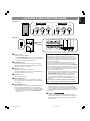
BGRT
English
YST-SW160/90
Active Servo Processing Subwoofer System
Caisson de grave avec asservissement actif
OWNER’S MANUAL
MODE D’EMPLOI
BEDIENUNGSANLEITUNG
BRUKSANVISNING
MANUALE DI ISTRUZIONI
MANUAL DE INSTRUCCIONES
GEBRUIKSAANWIJZING1
01-11,72_YST-SW160/90 ENG
1
00.7.20, 5:07 PM
Thank you for selecting this YAMAHA subwoofer system.
CAUTION: READ THIS BEFORE OPERATING YOUR UNIT.
1. To assure the finest performance, please read this manual
carefully. Keep it in a safe place for future reference.
2. Install this unit in a cool, dry, clean place, away from
windows, heat sources, sources of excessive vibration,
dust, moisture and cold. Avoid sources of humming
(transformers, motors). To prevent fire or electrical shock,
do not expose the unit to rain or water.
3. Never open the cabinet. If something drops into the set,
15. Secure placement or installation is the owner’s
responsibility.
YAMAHA shall not be liable for any accident caused
by improper placement or installation of speakers.
IMPORTANT
Please record the serial number of this unit in the space
below.
contact your dealer.
4. Do not use force on switches, controls or connection wires.
When moving the unit, first disconnect the power plug and
the wires connected to other equipment. Never pull the
wire itself.
Serial No.:
The serial number is located on the rear of the unit.
Retain this Owner’s Manual in a safe place for future
reference.
5. Do not attempt to clean the unit with chemical solvents;
this might damage the finish. Use a clean, dry cloth.
6. Be sure to read the “TROUBLESHOOTING” section
regarding common operating errors before concluding that
the unit is faulty.
7. When not planning to use this unit for long periods of time
(i.e., vacation, etc.), disconnect the AC power plug from
the wall outlet.
8. To prevent lightning damage, disconnect the AC power
plug when there is an electrical storm.
9. Since this unit has a built-in power amplifier, heat will
radiate from the rear panel. Therefore, place the unit apart
from the walls, allowing enough space above, behind and
on the both sides of the unit to prevent fire and damage.
Also, do not position with the rear panel facing down on
the floor or other surface.
<For U.K. and Europe models only>
Be sure to allow a space of at least 20 cm above, behind
and on the both sides of the unit.
10. Super-bass frequencies reproduced by this unit may cause
a turntable to generate a howling sound. In such a case,
move this unit away from the turntable.
WARNING
TO REDUCE THE RISK OF FIRE OR ELECTRIC SHOCK,
DO NOT EXPOSE THIS UNIT TO RAIN OR MOISTURE.
FOR CANADIAN CUSTOMERS
TO PREVENT ELECTRIC SHOCK, MATCH WIDE BLADE
OF PLUG TO WIDE SLOT AND FULLY INSERT.
THIS CLASS B DIGITAL APPARATUS COMPLIES WITH
CANADIAN ICES-003.
For U.K. customers
If the socket outlets in the home are not suitable for the plug
supplied with this appliance, it should be cut off and an
appropriate 3 pin plug fitted. For details, refer to the
instructions described below.
Note: The plug severed from the mains lead must be
destroyed, as a plug with bared flexible cord is hazardous if
engaged in a live socket outlet.
SPECIAL INSTRUCTIONS FOR U.K. MODEL
IMPORTANT
THE WIRES IN THE MAINS LEAD ARE COLOURED IN
ACCORDANCE WITH THE FOLLOWING CODE:
11. Vibration generated by super-bass frequencies may cause
images on a TV to be distorted. In such a case, move this
unit away from the TV set.
12. This unit features a magnetically shielded design, but there
is still a chance that placing it too close to a TV set might
impair picture color. Should this happen, move this unit
away from the TV set.
13. If you hear distortion (i.e., unnatural, intermittent “rapping”
or “hammering” sounds) coming from this unit, reduce the
volume level. Extremely loud playing of a movie
soundtrack’s low frequency, bass-heavy sounds or
similarly loud popular music passages can damage this
speaker system.
Blue: NEUTRAL
Brown: LIVE
As the colours of the wires in the mains lead of this
apparatus may not correspond with the coloured markings
identifying the terminals in your plug, proceed as follows:
The wire which is coloured BLUE must be connected to the
terminal which is marked with the letter N or coloured
BLACK. The wire which is coloured BROWN must be
connected to the terminal which is marked with the letter L or
coloured RED. Making sure that neither core is connected to
the earth terminal of the three pin plug.
14. Voltage Selector (General and China Models only)
The voltage selector on the rear panel of this unit must
be set for your local main voltage BEFORE plugging
into the AC main supply.
Voltages are AC 110/120/220/240V, 50/60 Hz.
2
01-11,72_YST-SW160/90 ENG
2
00.7.20, 5:07 PM
Caution ....................................................................... 2
Features ..................................................................... 3
Placement .................................................................. 3
Connections ............................................................... 4
Controls and their functions ....................................... 7
English
CONTENTS
Adjusting volume ........................................................ 8
Advanced YAMAHA Active Servo Technology .......... 10
Troubleshooting ....................................................... 11
Specifications ........................................................... 11
FEATURES
• This subwoofer system employs Advanced YAMAHA Active
Servo Technology which YAMAHA has developed for
reproducing higher quality super-bass sound. (Refer to page
10 for details on Advanced YAMAHA Active Servo
Technology.) This super-bass sound adds a more realistic,
theater-in-the-home effect to your stereo system.
• This unit can be added easily to your existing audio system
by connecting to either the speaker terminals or the line
output (pin jack) terminals of the amplifier.
• For the effective use of this unit, this unit’s super-bass sound
must be matched to the sounds of your main speakers. You
can create the best sound quality for various listening
conditions by using the HIGH CUT control and the PHASE
switch.
• The Automatic Standby function saves you the trouble of
pressing the STANDBY/ON button to turn the power on and
off.
• You can select bass effect suitable to the source by using
the BASS switch. YST-SW160 only
PLACEMENT
Å
ı
(
: subwoofer,
Ç
: main speaker)
One subwoofer will have a good effect on your audio system,
however, the use of two subwoofers is recommended to obtain
more presence.
If using one subwoofer, it is recommended to place it on the
outside of either the right or the left main speaker. (See fig. Å.)
If using two subwoofers, it is recommended to place them on
the outside of each main speaker. (See fig. ı.) The placement
shown in fig. Ç is also possible, however, if the subwoofer
system is placed directly facing the wall, the bass effect may
die because the sound from it and the sound reflected by the
wall may cancel. To prevent this, face the subwoofer system
obliquely to the wall as in fig. Å or ı.
Note
There may be a case that you cannot obtain enough superbass sounds from this unit when listening at the middle of the
room. This is because “standing waves” have developed
between two parallel walls and the bass sounds are canceled.
In such a case, face the unit obliquely to the wall. It also may
be necessary to break up the parallel surfaces by placing
bookshelves etc. along the walls.
3
01-11,72_YST-SW160/90 ENG
3
00.7.20, 5:07 PM
CONNECTIONS
Never plug in the subwoofer and other audio/video components until all connections are completed.
• When making connections between this unit and other components, be sure all connections are made firmly and correctly; L (left)
to L, R (right) to R, + to + and – to –.
• This unit can be connected to either the speaker terminals or the line output (pin jack) terminals of the amplifier. Choose one of
the connections shown below according to your audio system. Refer also to the owner’s manuals supplied for your audio system.
CONNECTING TO SPEAKER TERMINALS OF THE AMPLIFIER
Illustrations of the unit used in this
manual are of YST-SW160 unless
mentioned otherwise.
Using one unit
When your amplifier has one set of speaker terminals
• Disconnect your main speakers from the amplifier if connected, and connect them
to the speaker terminals of this unit.
OUTPUT
TO SPEAKERS
Right speaker
INPUT2
This unit
LOW
FROM AMPLIFIER
INPUT1
OUTPUT
TO SPEAKERS
INPUT2
AUTO
STANDBY
LOW
FROM AMPLIFIER
INPUT1
HIGH
PHASE
NOM
REV
AUTO
STANDBY
PHASE
HIGH
NOM
BASS
REV
Left speaker
MOVIE MUSIC
OFF
BASS
MOVIE MUSIC
OFF
Amplifier
POWER
ON
OFF
To AC outlet
Speaker terminals
When your amplifier has two sets of speaker terminals
This unit
OUTPUT
TO SPEAKERS
INPUT2
AUTO
STANDBY
LOW
FROM AMPLIFIER
INPUT1
HIGH
PHASE
NOM
REV
OUTPUT
TO SPEAKERS
INPUT2
AUTO
STANDBY
PHASE
BASS
BASS
MOVIE MUSIC
OFF
LOW HIGH
FROM AMPLIFIER
INPUT1
NOM
REV
MOVIE MUSIC
OFF
POWER
ON
OFF
Left speaker
Right speaker
To AC outlet
Amplifier
Speaker terminals
A
B
(Both A and B speaker outputs
must be ON.)
4
01-11,72_YST-SW160/90 ENG
4
00.7.20, 5:07 PM
English
Using two units
Disconnect your main speakers from the amplifier if connected, and connect them to the speaker terminals of this unit.
Right speaker
Left speaker
OUTPUT
TO SPEAKERS
INPUT2
AUTO
STANDBY
PHASE
BASS
OUTPUT
TO SPEAKERS
INPUT2
AUTO
STANDBY
PHASE
BASS
This unit
This unit
LOW
FROM AMPLIFIER
INPUT1
OUTPUT
TO SPEAKERS
INPUT2
AUTO
STANDBY
LOW
FROM AMPLIFIER
INPUT1
HIGH
PHASE
NOM
REV
HIGH
NOM
REV
LOW
MOVIE MUSIC
OFF
FROM AMPLIFIER
INPUT1
HIGH
NOM
REV
MOVIE MUSIC
OFF
OUTPUT
TO SPEAKERS
BASS
INPUT2
AUTO
STANDBY
LOW
MOVIE MUSIC
FROM AMPLIFIER
INPUT1
OFF
HIGH
PHASE
NOM
REV
BASS
MOVIE MUSIC
OFF
Amplifier
POWER
POWER
ON
ON
OFF
OFF
To AC outlet
To AC outlet
Speaker terminals
Connecting to this unit’s OUTPUT/INPUT terminals
For connections, keep the speaker wires as short as possible.
(Cut the excessive wire, if necessary.) If the connections are faulty,
no sound will be heard from the speakers. Make sure that the
polarity of the speaker wires is correct, by observing + and –
markings. If these wires are reversed, the sound will be unnatural
and will lack bass.
Do not let the core of the speaker wires touch each other
and do not let them touch the metal parts of this unit as this
could damage this unit, your amplifier and/or speakers.
* Banana Plug connections are also possible (except for U.K.
and Europe models). Simply insert the Banana Plug connector into the corresponding terminal.
How to Connect:
Red: positive (+)
Black: negative (–)
1 Unscrew the knob.
2 Insert the core of the
wire. [Remove
approx. 5 mm (1/4”)
insulation from the
speaker wires.]
3 Tighten the knob to
secure the wire firmly.
5
01-11,72_YST-SW160/90 ENG
5
00.7.20, 5:07 PM
CONNECTING TO LINE OUTPUT (PIN JACK) TERMINALS OF THE AMPLIFIER
• Connect the main speakers to the speaker output terminals of the amplifier.
• Amplifier line output terminals are generally labeled PRE OUT or SUBWOOFER OUT.
• To connect with a YAMAHA DSP amplifier, connect the SUBWOOFER (or LOW PASS etc.) terminal on the rear of the DSP
amplifier to either the left (L) or right (R) INPUT 2 terminal.
Using one unit
This unit
Left speaker
OUTPUT
TO SPEAKERS
INPUT2
AUTO
STANDBY
LOW
FROM AMPLIFIER
INPUT1
HIGH
PHASE
NOM
REV
OUTPUT
TO SPEAKERS
INPUT2
AUTO
STANDBY
PHASE
Right speaker
BASS
BASS
MOVIE MUSIC
OFF
LOW HIGH
FROM AMPLIFIER
INPUT1
NOM
REV
MOVIE MUSIC
OFF
POWER
ON
OFF
To AC outlet
Pin plug
cords
‹YAMAHA DSP amplifier›
SUBWOOFER
Amplifier
‹Amplifier›
PRE OUT
Using two units
Right speaker
Left speaker
OUTPUT
TO SPEAKERS
INPUT2
AUTO
STANDBY
LOW
FROM AMPLIFIER
INPUT1
This unit
OUTPUT
TO SPEAKERS
INPUT2
AUTO
STANDBY
LOW
FROM AMPLIFIER
INPUT1
HIGH
PHASE
NOM
REV
PHASE
NOM
HIGH
REV
OUTPUT
TO SPEAKERS
BASS
INPUT2
LOW HIGH
MOVIE MUSIC
FROM AMPLIFIER
INPUT1
OFF
AUTO
STANDBY
PHASE
NOM
REV
BASS
MOVIE MUSIC
OFF
Pin plug
cords
This unit
BASS
OUTPUT
TO SPEAKERS
MOVIE MUSIC
INPUT2
AUTO
STANDBY
LOW
FROM AMPLIFIER
INPUT1
OFF
HIGH
PHASE
NOM
REV
BASS
MOVIE MUSIC
OFF
Amplifier
POWER
POWER
ON
ON
OFF
OFF
To AC outlet
To AC outlet
Notes on the above connections
• When connected to line output terminals of the amplifier, other speakers should not be connected to the OUTPUT terminals on
the rear panel of the subwoofer. If connected, they will not produce sound.
• When connecting this unit to a monaural line output terminal of the amplifier, connect to either the left or right INPUT 2 terminal.
• For using a power amplifier and a preamplifier, the preamplifier must have two sets of PRE OUT terminals. If your preamplifier
has only one set of PRE OUT, connect this unit to the speaker terminals. (See page 4.)
6
01-11,72_YST-SW160/90 ENG
6
00.7.20, 5:07 PM
English
CONTROLS AND THEIR FUNCTIONS
Front panel
STANDBY/ON
HIGH CUT
40 Hz
140 Hz
VOLUME
0
YST-SW160
10
STANDBY/ON
HIGH CUT
40 Hz
~
Ÿ
140 Hz
!
YST-SW90
VOLUME
0
STANDBY/ON
10
⁄
HIGH CUT
50 Hz
~
Ÿ
150 Hz
VOLUME
0
!
10
⁄
Rear panel
OUTPUT
TO SPEAKERS
POWER
OUTPUT
TO SPEAKERS
INPUT2
AUTO
STANDBY
PHASE
INPUT2
AUTO
STANDBY
PHASE
BASS
BASS
ON
LOW
FROM AMPLIFIER
INPUT1
HIGH
NOM
REV
MOVIE MUSIC
OFF
OFF
LOW HIGH
@
NOM
REV
MOVIE MUSIC
POWER
ON
OFF
FROM AMPLIFIER
INPUT1
OFF
¤
~ Power indicator
Lights up while this unit is ON.
* If the AUTO STANDBY switch on the rear panel is set to
the LOW or HIGH position, this indicator is illuminated
dimly when no signal is input to this unit.
Ÿ STANDBY/ON button
Each press of this button turns the unit on and off (on
standby). A small amount of power is always consumed
even while this unit is on standby.
! HIGH CUT control
Adjusts the high frequency cut off point.
Frequencies higher than the frequency selected with this
control are all cut off (and not output).
⁄ VOLUME control
Adjusts the volume level.
@ Main POWER switch
Normally, leave this switch to the ON position. When you
will not use this unit for a long period, set this switch to the
OFF position.
¤ AUTO STANDBY switch
With this switch, you can activate the Automatic Standby
function. Normally, set the switch to the LOW position.
To cancel this function, set the switch to the OFF position.
* Change the setting of this switch only when the power of
this unit is on standby (by setting the STANDBY/ON
button to OFF).
#
‹
Automatic Standby function
When you play a source, the power of this unit turns on
automatically by sensing audio signals input to this unit. This
unit turns into the standby mode automatically if the source
being played is stopped or the low frequency input signal is
cut off for several minutes.
This function will operate by sensing a certain level of low
frequency input signal. Its sensitivity is high in the HIGH
position and low in the LOW position of the AUTO STANDBY
switch. In the HIGH position, the power will turn on even with
a low level of input signal, but on the other hand this unit may
not turn into the standby mode when there is an input signal
even if its level is extremely low.
* There may be a case that the power turns on unexpectedly
by sensing noise from other appliances. If it occurs, set the
AUTO STANDBY switch to the OFF or LOW position.
* The level of low frequency input signal differs with each
source, and each different part on the same source. So,
this function may not operate properly depending on some
sources.
This function is available only when the power of this
unit is on (by setting the STANDBY/ON button Ÿ to ON).
# PHASE switch
Normally this switch is to be set to the REV (reverse)
position. However, according to your speaker systems or
the listening condition, there may be a case when better
sound quality is obtained by setting this switch to the NOM
(normal) position. Select the better position by monitoring
the sound.
‹ BASS switch
YST-SW160 only
By setting this switch to the MOVIE position, the bass
sound in video software is well reproduced. By setting it to
the MUSIC position, the bass sound in audio software is
well reproduced.
7
01-11,72_YST-SW160/90 ENG
7
00.7.20, 5:08 PM
ADJUSTING VOLUME
Adjustment of the HIGH CUT control, the VOLUME control and the PHASE switch needs to be changed according to the main
speakers, listening condition, source, etc.
Front panel
Rear panel
PHASE
YST-SW160
STANDBY/ON
HIGH CUT
YST-SW90
VOLUME
STANDBY/ON
HIGH CUT
VOLUME
NOM
40 Hz
3
1
2
3
4
5
140 Hz
5
0
10
50 Hz
1,6
3
150 Hz
5
0
REV
10
1,6
7
Set the VOLUME control to minimum (0).
Turn on the other components.
Press the STANDBY/ON button to turn on this unit.
Play any source and adjust the amplifier’s volume control to the desired listening level.
Adjust the HIGH CUT control according to the main speakers connected.
Normally, set the control to the main speaker’s rated minimum reproducible frequency*. If the desired response
cannot be obtained, adjust the control again to your preference.
* The main speaker’s rated minimum reproducible frequency can be looked up in the speakers’ catalog or
owner’s manual.
6
Turn up the VOLUME control gradually to adjust the volume balance between this unit and the
main speakers.
Normally, set the control to the level where you can obtain a little more bass effect than when this unit is not used.
If the desired response cannot be obtained, adjust the control again to your preference.
7
Set the PHASE switch to the position which gives you the better bass sound.
Normally, set the switch to the REV (reverse) position. If the desired response cannot be obtained, set the switch
to the NOM (normal) position.
Once the volume balance between this unit and the main speakers is adjusted, you can adjust the volume of your
whole sound system by using only the amplifier’s volume control.
FREQUENCY RESPONSE
This unit’s frequency response
YST-SW160
YST-SW90
dB
dB
HIGH CUT 40 Hz
HIGH CUT 90 Hz
90
HIGH CUT 100 Hz
90
HIGH CUT 150 Hz
HIGH CUT 140 Hz
80
80
70
70
50
50
40
40
8
01-11,72_YST-SW160/90 ENG
HIGH CUT 50 Hz
60
60
20
50
8
100
200
500Hz
20
50
00.7.20, 5:08 PM
100
200
500Hz
English
The figures below show the optimum adjustment of each control and the frequency characteristics when this unit is
combined with a typical main speaker system.
EX.1
When combined with a 4” or 5” (10 cm or 13 cm) acoustic suspension, 2 way system main speakers
YST-SW160
YST-SW90
dB
HIGH CUT
dB
Combined frequency response
VOLUME
HIGH CUT
VOLUME
Combined frequency response
90
90
80
40 Hz
140 Hz
0
80
YST-SW160
10
50 Hz
150 Hz
0
70
70
* One graduation of this
control represents 10 Hz. 60
PHASE–Set to the REV
(reverse) position.
* One graduation of this
control represents 10 Hz.
Main
speaker’s
response
50
PHASE–Set to the REV
(reverse) position.
40
20
EX.2
YST-SW90
10
50
100
200
Main
speaker’s
response
60
50
40
500Hz
20
50
100
200
500Hz
When combined with an 8” or 10” (20 cm or 25 cm) acoustic suspension, 2 way system main speakers
YST-SW90
YST-SW160
dB
HIGH CUT
dB
Combined frequency response
VOLUME
HIGH CUT
90
90
80
40 Hz
140 Hz
0
80
10
50 Hz
YST-SW160
150 Hz
0
YST-SW90
10
70
70
* One graduation of this
control represents 10 Hz. 60
PHASE–Set to the REV
(reverse) position.
Combined frequency response
VOLUME
* One graduation of this
control represents 10 Hz.
Main
speaker’s
response
PHASE–Set to the REV
(reverse) position.
50
40
Main
speaker’s
response
60
50
40
20
50
100
200
500Hz
20
50
100
200
500Hz
9
01-11,72_YST-SW160/90 ENG
9
00.7.20, 5:08 PM
ADVANCED YAMAHA ACTIVE SERVO TECHNOLOGY
The theory of Yamaha Active Servo Technology has been based
upon two major factors, the Helmholtz resonator and negativeimpedance drive. Active Servo Processing speakers reproduce
the bass frequencies through an “air woofer”, which is a port or
opening in the speaker’s cabinet. This opening is used instead
of, and performs the functions of, a woofer in a conventionally
designed speaker system. Thus, signals of low amplitude within
the cabinet can, according to the Helmholtz resonance theory,
be output from this opening as waves of great amplitude if the
design is such that the size of the opening and the volume of
the cabinet are in the correct proportion to satisfy a certain
ratio.
In order to accomplish this, moreover, the amplitudes within
the cabinet must be both precise and of sufficient power
because these amplitudes must overcome the “load” presented
by the air that exists within the cabinet.
Thus it is this problem that is resolved through the employment
of a design in which the amplifier functions to supply special
signals. If the electrical resistance of the voice coil could be
reduced to zero, the movement of the speaker unit would
become linear with respect to signal voltage, and, to accomplish
this, a special negative-impedance output-drive amplifier for
subtracting output impedance of the amplifier is used.
By employing negative-impedance drive circuits, the amplifier
is able to generate precise, low-amplitude low-frequency waves
with superior damping characteristics, and these waves are
then radiated from the cabinet opening as high-amplitude
signals. The system can, therefore, by employing the negativeimpedance output drive amplifier and a speaker cabinet with
the Helmholtz resonator, reproduce an extremely wide range
of frequencies with amazing sound quality and less distortion.
The features described above, then, are combined to be the
fundamental structure of the conventional Yamaha Active Servo
Technology.
Our new Active Servo Technology — Advanced Yamaha Active
Servo Technology — adopted Advanced Negative Impedance
Converter (ANIC) circuits, which allows the conventional
negative impedance converter to dynamically vary in order to
select an optimum value for speaker impedance variation. With
this new ANIC circuits, Advanced Yamaha Active Servo
Technology can provide more stable performance and improved
maximum sound pressure compared with the conventional
Yamaha Active Servo Technology, resulting in more natural and
energetic bass reproduction.
Air woofer
(Helmholtz resonator)
Cabinet
High-amplitude
bass sound
Port
Advanced NegativeImpedance Converter
Active
Servo
Processing
Amplifier
Signals
Signals of low amplitude
10
01-11,72_YST-SW160/90 ENG
10
00.7.20, 5:08 PM
If the unit fails to operate normally, check the following points to determine whether the fault can be corrected by the simple measures suggested. If it cannot be corrected, or if the fault is not listed in the SYMPTOM column, disconnect the power cord and contact
your authorized YAMAHA dealer or service center for help.
SYMPTOM
CAUSE
REMEDY
The power cannot be turned on.
The power cord is not plugged in, or the Main
POWER switch is set to the OFF position.
Plug the power cord into an AC outlet and/or set the
Main POWER switch to the ON position.
No sound.
The VOLUME control is set to 0.
Turn the VOLUME control to right.
Speaker wires are not connected securely.
Connect them securely.
Speaker wires are connected incorrectly.
Connect them correctly; L (left) to L, R (right) to R, + to
+ and – to –.
Setting of the PHASE switch is not proper.
Set the switch to the other position.
A source sound with few bass frequencies is
played.
Play a source sound with bass frequencies.
Set the HIGH CUT control to a higher position.
It is influenced by standing waves.
Reposition the subwoofer or break up the parallel
surface by placing bookshelves etc. along the walls.
The Main POWER switch is set to the OFF
position.
Set the Main POWER switch to the ON position.
The STANDBY/ON button is set to OFF.
Set the STANDBY/ON button to ON.
The AUTO STANDBY switch is set to the OFF
position.
Set the AUTO STANDBY switch to the HIGH or LOW
position.
The level of input signal is too low.
Set the AUTO STANDBY switch to the HIGH
position.
The unit turns off (on standby)
unexpectedly.
The level of input signal is too low.
Set the AUTO STANDBY switch to the HIGH
position.
The unit turns on unexpectedly.
An influence of noise generated from external
equipment etc.
Move the unit farther away from such equipment and/
or change the position of connected speaker wires.
Otherwise, set the AUTO STANDBY switch to the
OFF position.
Sound level is too low.
The unit does not turn on
automatically.
SPECIFICATIONS
YST-SW160
Type ................ Active Servo Processing Subwoofer System
Speaker Unit .................... 20 cm (8”) cone woofer (JA2160)
magnetic shielding type x 2
Amplifier Output ........................................... 150 W/5 ohms
High-Cut Filter ......................... 40 Hz–140 Hz (–24 dB/oct.)
Frequency Response ..................... 20 Hz–160 Hz (–10 dB)
Power Supply
U.S.A. and Canada models .................. AC 120 V, 60 Hz
Australia model ..................................... AC 240 V, 50 Hz
U.K. and Europe models ...................... AC 230 V, 50 Hz
General and China models
................... AC 110/120/220/240 V, 50/60 Hz
.................. (Adjustable with Voltage Selector)
Power Consumption .................................................... 100 W
Dimensions (W × H × D) ........... 235 mm × 602 mm × 463 mm
(9-5/16” × 23-3/4” × 18-1/4”)
Weight ...................................................... 20 kg (44 lbs. 1 oz.)
YST-SW90
Power Consumption ...................................................... 80 W
Dimensions (W × H × D) ........... 235 mm × 485 mm × 409 mm
(9-5/16” × 19-1/8” × 16-1/8”)
Weight .................................................... 14 kg (30 lbs. 13 oz.)
Type ................ Active Servo Processing Subwoofer System
Speaker Unit .................... 20 cm (8”) cone woofer (JA2161)
magnetic shielding type
Amplifier Output ........................................... 100 W/5 ohms
High-Cut Filter ......................... 50 Hz–150 Hz (–24 dB/oct.)
Frequency Response ..................... 23 Hz–170 Hz (–10 dB)
Power Supply
U.S.A. and Canada models .................. AC 120 V, 60 Hz
Australia model ..................................... AC 240 V, 50 Hz
U.K. and Europe models ...................... AC 230 V, 50 Hz
General and China models
................... AC 110/120/220/240 V, 50/60 Hz
(Adjustable with Voltage Selector)
01-11,72_YST-SW160/90 ENG
11
* Design and specifications are subject to change without notice.
* Design and specifications are subject to change without notice.
11
00.7.20, 5:08 PM
English
TROUBLESHOOTING
YAMAHA ELECTRONICS CORPORATION, USA 6660 ORANGETHORPE AVE., BUENA PARK, CALIF. 90620, U.S.A.
YAMAHA CANADA MUSIC LTD. 135 MILNER AVE., SCARBOROUGH, ONTARIO M1S 3R1, CANADA
YAMAHA ELECTRONIK EUROPA G.m.b.H. SIEMENSSTR. 22-34, 25462 RELLINGEN BEI HAMBURG, F.R. OF GERMANY
YAMAHA ELECTRONIQUE FRANCE S.A. RUE AMBROISE CROIZAT BP70 CROISSY-BEAUBOURG 77312 MARNE-LA-VALLEE CEDEX02, FRANCE
YAMAHA ELECTRONICS (UK) LTD. YAMAHA HOUSE, 200 RICKMANSWORTH ROAD WATFORD, HERTS WD1 7JS, ENGLAND
YAMAHA SCANDINAVIA A.B. J A WETTERGRENS GATA 1, BOX 30053, 400 43 VÄSTRA FRÖLUNDA, SWEDEN
YAMAHA MUSIC AUSTRALIA PTY, LTD. 17-33 MARKET ST., SOUTH MELBOURNE, 3205 VIC., AUSTRALIA
Printed in Malaysia
12
01-11,72_YST-SW160/90 ENG
12
00.7.20, 5:08 PM
V304660