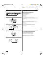
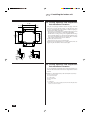
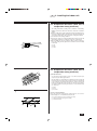
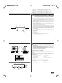
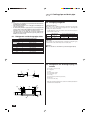
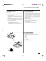
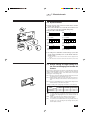
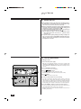
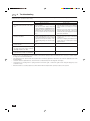
1
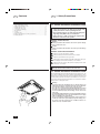
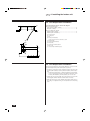
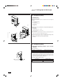
Air-Conditioners
PLH-2, 2.5KKC
FOR INSTALLER
ON/OFF –
CENTRALLY CONTROLLED
ON OFF
CHECK
CLOCK
1Hr.
˚C
FILTER
CHECK MODE
STAND BY
DEFROST
E
˚C
TEST RUN
NOT AVAILABLE
INSTALLATION
MANUAL
For safe and correct use, please read this installation manual thoroughly before installing the air-conditioner unit.
E
Contents
1. Safety Precautions ................................................................................... 2
2. Indoor unit installation location ................................................................. 7
3. Outdoor unit installation location .............................................................. 8
4. Installing the indoor unit .......................................................................... 11
5. Installing the outdoor unit ....................................................................... 15
6. Cooling pipe and drain pipe ................................................................... 16
7. Electrical work ........................................................................................ 20
8. Test run .................................................................................................. 28
9. Troubleshooting ..................................................................................... 30
10. Field electrical wiring (Power wiring specifications) ............................... 31
11. Installing the grille .................................................................................. 32
E
1. Safety Precautions
1.1. Before installation and electric work
s Since this unit contains rotating parts and parts which
could cause an electric shock,be sure to read all of the
“Safety Precautions” before operating the unit.
s The “Safety Precautions” provide very important points
regarding safety. Make sure you follow them.
s Please report to or take consent by the supply authority before connection to the system.
Symbols used in the text
Warning:
Describes precautions that should be observed to prevent danger
of injury or death to the user.
Caution:
Describes precautions that should be observed to prevent damage
to the unit.
Symbols used in the illustrations
: Indicates an action that must be avoided.
: Indicates that important instructions must be followed.
: Indicates a part which must be grounded.
: Indicates that caution should be taken with rotating parts. (This symbol is displayed on the main unit label.) <Color: Yellow>
: Indicates the main switch. (This symbol is displayed on the main
unit label.) <Color: Blue>
Warning:
Carefully read the labels affixed to the main unit.
1.1. Before installation and electric work
This Installation Manual and the Operation Manual should be given to the
user of the air conditioner. The user should keep both manuals in a place
where they are accessible at any time. If the air conditioner must be moved
or repaired, these manuals should be made available to the service personnel. These manuals should be kept with the air conditioner at all times
and passed on to subsequent users.
•
•
•
•
2
Warning:
The unit should not be installed by the user. Ask the dealer or an
authorized technician to install the unit. If the unit is installed improperly, water leakage, electric shock or fire may result.
Use only accessories authorized by Mitsubishi Electric and ask
the dealer or an authorized technician to install them. If accessories are installed improperly, water leakage, electric shock or fire
may result.
The Installation Manual details the suggested installation method.
Any structural alteration necessary for installation must comply
with local building code requirements.
The user should never attempt to repair the unit or transfer it to
another site. If the unit is repaired improperly, water leakage, electric shock or fire may result. If the air conditioner must be repaired or moved, consult the dealer.
E
1. Safety Precautions
1.1. Before installation and electric work
•
•
•
•
•
Warning:
The unit must be securely installed on a structure that can sustain its weight. If the unit is mounted on an unstable structure, it
may fall down causing injuries.
Use only specified cables for wiring. The connections must be
made securely without pulling on the terminals. Improper connections or installation may generate heat or cause a fire.
The unit should be installed according to the instructions in order to minimize the risk of damage from earthquakes, typhoons
or strong winds. An improperly installed unit may fall down and
cause damage or injuries.
When installing an optional air cleaner or humidifier, be sure to
use only products specified by Mitsubishi.
All accessories must be installed by an authorized technician.
The user must not try to install accessories. Improperly installed
accessories can cause water leakage, electric shock or fire.
Do not turn on the power until installation has been completed.
Failure to do so may cause an electric shock or fire.
1.1. Before installation and electric work
•
•
•
•
•
Warning:
All electric work must be performed by a licensed technician, according to local regulations and the instructions given in this
manual.
The units should be powered by dedicated power lines. Power
lines with insufficient capacity or improper electrical work may
result in electric shock or fire.
The terminal block cover of the outdoor unit must be firmly attached to prevent entry of dust and moisture. Improper mounting
of the cover can cause electric shock or fire.
Use only the specified refrigerant (R-22) to charge the refrigerant
circuit. Do not mix it with any other refrigerant and do not allow
air to remain in the circuit. Air enclosed in the circuit can cause
pressure peaks resulting in a rupture and other hazards.
If the air conditioner is installed in a small room, measures must
be taken to prevent the refrigerant concentration in the room from
exceeding the safety limit in the event of refrigerant leakage.
Consult the dealer regarding the appropriate measures to prevent the allowable concentration from being exceeded. Should
the refrigerant leak and cause the concentration limit to be exceeded, hazards due to lack of oxygen in the room could result.
Ventilate the room if refrigerant leaks during operation.
If the refrigerant comes in contact with a flame, poisonous gases
will be released.
3
E
1. Safety Precautions
1.1. Before installation and electric work
•
•
•
•
Caution:
Do not install the equipment where combustible gas may leak
and accumulate resulting in fire.
Do not keep food, plants, caged pets, artwork or precision instruments in the indoor unit’s direct airflow or too close to the unit,
as these items can be damaged by temperature changes or dripping water.
When the room humidity exceeds 80% or when the drain pipe is
clogged, water may drip from the indoor unit. Do not install the
indoor unit where such dripping could cause damage.
The outdoor unit produces condensation during the heating operation. Make sure to provide drainage around the outdoor unit if
such condensation is likely to cause damage.
This air conditioner should not be installed in areas exposed to
thick steam, volatile oil (including machine oil) or sulphuric smoke,
as this could significantly reduce its performance and damage
the internal parts.
1.1. Before installation and electric work
Fuse or breaker
A Fuse or breaker
B Main power switch
C Power supply wiring
Disconnection must be incorporated in the fixed wiring.
A
•
B
•
•
C
•
Caution:
When installing the power lines, do not apply tension to the cables, as this could loosen the connections, generate heat and
cause a fire.
Use only a fuse of specified capacity. A fuse of larger capacity or
a steel or copper wire could cause a general unit failure or fire.
Make sure to install an earth leakage breaker as this device helps
reduce the risk of electric shocks. Installation of an earth leakage
breaker is mandatory in some areas.
For the power lines, use standard cables of sufficient current capacity. Otherwise, current leakage, overheating or fire may occur.
Earth connection
Caution:
Make sure to install a grounding line. Do not connect the grounding
line to gas or water pipes, lightning conductors or telephone grounding lines. Improper grounding may cause an electric shock.
“WARNING-THIS APPLIANCE MUST BE EARTHED”
4
E
1. Safety Precautions
1.1. Before installation and electric work
Drain piping
•
•
Caution:
Install drain piping according to this Installation Manual to ensure proper drainage. Place thermal insulation on the pipes to
prevent condensation. Improper drain piping may cause water
leakage and damage to furniture or other possessions.
Thermal insulation of the drain pipes is necessary to prevent dew
condensation. If the drain pipes are not properly insulated, condensation will result and drip on the ceiling, floor or other possessions.
Miscellaneous
Caution:
Do not wash the air conditioner units. Washing them may cause an
electric shock.
1.1. Before installation and electric work
•
•
•
•
Caution:
Be extremely careful when transporting the units. Two or more
persons are needed to handle the unit, as it weighs 20 kg or more.
Do not grasp the bands of the crate. Instead, insert your hands
into the cutouts in the crate. Wear protective gloves to extract the
unit from the crate and to move it, as you could injure your hands
on the fins or other parts.
Transport the unit in its package and unpack it only on the installation site.
The base and attachments of the outdoor unit should be periodically checked for looseness, cracks or other damage. If such defects are left uncorrected, the unit may fall and cause personal
injury or property damage.
Be sure to safely dispose of the packaging materials. Packaging
materials, such as catches and other metal or wooden parts, may
cause stabs or other injuries.
5
E
1. Safety Precautions
1.2. Before starting the trial run
•
•
•
•
Caution:
Before starting operation, check that all panels, guards and other
protective parts are correctly installed. Rotating, hot or high voltage parts can cause injuries.
Do not touch the refrigerant pipes with bare hands during operation. The refrigerant pipes are sometimes hot and sometimes cold
depending on the condition of the flowing refrigerant. Your hands
may suffer burns or frostbite if you touch the pipes.
Turn on the main power switch more than twelve hours before
starting operation. Starting operation just after turning the main
power switch on can result in severe damage to internal parts.
Keep the main power switch turned on during the operation season.
Keep the outlets and inlets free of obstacles. Otherwise, the performance may be reduced or operation may stop.
1.2. Before starting the trial run
•
•
•
6
Caution:
Do not touch any switch with wet fingers, as this can cause an
electric shock.
Do not operate the air conditioner without the air filter set in place.
Dust may accumulate, and cause a failure.
After stopping operation, be sure to wait for five minutes before
turning off the main power switch. Otherwise, water leakage or
unit failure may occur.
E
2. Indoor unit installation location
2.1. Outline dimensions
(mm)
30
H
Models
PLH-2, 2.5
D
W
W
760
D
760
H
307
•
Mount the indoor unit on a wall strong enough to withstand the weight
of the unit.
•
Select a location so that air can be blown into all corners of the room.
•
Avoid locations exposed to outside air.
•
Select a location free of obstructions to the airflow in and out of the
unit.
•
Avoid locations exposed to steam or oil vapour.
•
Avoid locations where combustible gas may leak, settle or be generated.
•
Avoid installation near machines emitting high-frequency waves (highfrequency welders, etc.)
•
Avoid locations where the airflow is directed at a fire alarm sensor.
(Hot air could trigger the alarm during the heating operation.)
•
Avoid places where acidic solutions are frequently handled.
•
Avoid places where sulphur-based or other sprays are frequently used.
2.2. Service space
•
Select ideal blowing direction according to the shape of room and installing position.
A Ceiling
B Ceiling panel
C Obstacle
D 1 m or more
E 50 cm or more (Entire periphery)
F Panel
A
•
Reserve the above mentioned space for doing the piping and wiring
work, as well as for the maintenance work which is done from the
bottom & left/right sides. Similarly, reserve as much space as possible
to facilitate work & safety at the time of suspending.
D
B
F
C
E
7
E
2. Indoor unit installation location
E
3. Outdoor unit installation location
2.3. Refrigerant pipes
s Check that the difference between the heights of the indoor and
outdoor units, the length of refrigerant pipe, and the number of
bends in the pipe are within the limits shown below.
(A) Pipe length
(one way)
max. 40 m
max. 50 m
Models
PLH-2
PLH-2.5
A
D
•
(B) Height
difference
max. 40 m
max. 50 m
(C) Number of
bends (one way)
max. of 12
max. of 15
Height difference limitations are binding regardless of which unit, indoor or outdoor, is positioned higher.
A Length of refrigerant pipe
B Height difference
B
C Number of bends
D Indoor unit
E
E Outdoor unit
C
3.1. Outline dimensions
(mm)
Models
PUH-2
PUH-2.5
A
500
500
B
185
185
C
330
330
•
Avoid locations exposed to direct sunlight or other sources of heat.
•
If direct sunlight cannot be avoided, always install a sunshade to protect the outdoor unit from the sun.
•
Select a location from which noise emitted by the unit will not inconvenience neighbours.
•
Bear in mind that during operation, drain water may flow from the unit.
•
Avoid locations where the unit could be covered by snow.
In areas where heavy snow fall is anticipated, special precautions must
be taken to prevent the snow from blocking the air outlet or blowing
directly against it, as this would reduce the airflow and cause a malfunction.
•
Select a location permitting easy wiring and piping access to the power
source and indoor unit.
A
B
8
H
650
850
Avoid locations where combustible gas may leak, settle or be generated.
H
C
D
295
295
•
D
W
W
870
870
E
1
;;;
;;;
;;
;;
A
2
3. Outdoor unit installation location
3.2. Ventilation and service space
When installing a single outdoor unit
1 Service space
Maintain an easily accessible service space in front of the unit as shown
in the diagram.
C
A 10 mm or more
D
B
;;;;
;;;;;
;;;;
;;;;;
;;;;
;;;;;
;;;;;
;;;;
;;
;;;;
;;
;;;
;;;;
;;;;;
;;;
;;;;;
;;;;;
;;;;;
;;;;;
;;;;;
B 500 mm or more
C 500 mm or more
D Service space
2 Top obstacles
If there are no obstacles in front or at the left or right of the unit, obstacles
above the unit are permitted as shown in the diagram.
F
E 100 mm or more
F 500 mm or more
•
The front, right and left sides must be free of obstacles.
E
3
3 Unobstructed front (blowing side)
If the size of the space reserved for the unit is as shown in the diagram,
the unit can be installed so that obstacles are at the right, left and rear.
G 10 mm or more
H 200 mm or more
H
G
•
The front and top must be unobstructed.
•
The height of obstacles on either side must be the same or lower than
that of the outdoor unit.
G
4
3.2. Ventilation and service space
4 Obstacles in the front (blowing side) only
If there are obstacles in front of the unit, keep the back, left/right, & top
unobstructed.
I Min. 500 mm
I
;;;;;
;;;;;
;;;;;
;;;;;
;;;;;
;;;;;
;;;;;
;;;;; ;;;;;
5
N
M
J, K
6
L
7
Q
P
5 Obstacles at the front & rear only
The outdoor unit cannot be used except if the following conditions are
met:
An optional outdoor air outlet guide (left/right & top unobstructed) must be
fitted.
Moreover, if there is no natural wind flowing between the obstacles, keep
the height or width of the obstacles within the following range to prevent
the risk of short cycling. (If either the front or rear satisfies the requirements, there is no special restriction on the remaining side).
J Obstruction width: 1.5 times the width of outdoor unit or smaller
K Obstruction height: Unit height or lower
L Air outlet guide
M Min. 500 mm
N Min. 100 mm
6 Obstacles on 4 surrounding sides
The unit cannot be used if there are obstacles on all 4 surrounding sides,
even if there is more than the prescribed amount of space around the
outdoor unit and if the top is unobstructed.
7 Obstacles at the front & rear
This unit cannot be used if the following conditions are met:
P Max. 3000 mm
Q Max. 100 mm
9
E
;;;;;;;;;;;
;;;;;;;;;;;
1
C
B
E
D
3. Outdoor unit installation location
3.2. Ventilation and service space
When installing many outdoor units
1 Side-by-side arrangement
Remove the side screw on the pipe cover.
Keep the top unobstructed.
A
A Min. 100 mm
B Min.10 mm
C Min. 200 mm
D Up to 10 units (When the air outlet guides (sold separately) are used, no
more than five units should be arranged side by side.)
2
F
E Min. 1000 mm
•
G
Refrigerant piping and electric wiring cannot be attached on the right
side.
2 Face-to-face arrangement (with air outlet guide)
Fit an optional outdoor air outlet guide on each unit and set them to “upward blow”.
F Min. 200 mm
G Min. 500 mm
3
H
3 Face-to-face arrangement (without air outlet guides)
H Min. 200 mm
I Min. 1200 mm
I
3.2. Ventilation and service space
4
4 Parallel arrangement (with air outlet guides)
Fit an optional outdoor air outlet guide on each unit.
J Min. 1000 mm
5 Parallel arrangement (without air outlet guides)
J
5
K
10
K Min. 3000 mm
E
3. Outdoor unit installation location
E
4. Installing the indoor unit
3.2. Ventilation and service space
1
Installation on a rooftop or other windy places
When installing the unit on a rooftop or other location unprotected from
the wind, situate the unit’s air outlet so that it is not directly exposed to
strong winds. Strong wind entering the air outlet may impede the normal
airflow and cause malfunctions.
The following shows three examples of precautions against strong winds.
1 Face the outlet toward any available wall at least 50 cm away from
the wall.
2
2 Install an optional air outlet guide and if the unit is installed at a
place where the powerful blast of a typhoon, etc. comes directly
into the air outlet.
A Air outlet guide
A
3 Position the unit so that the air outlet blows perpendicularly to
the seasonal wind direction, if possible.
B Wind direction
3
B
B
90°
1
2
4.1. Check the indoor unit accessories
and parts
The indoor unit comes with the following parts and accessories.
1 Installation template × 1
2 Washers (with insulation) × 4
Washers (without insulation) × 4
3
4
3 Pipe cover (for refrigerant piping joint)
small diameter × 1
large diameter × 1
4 Band for temporary tightening of pipe cover
5 Screw with the washers M5 × 25
for mounting grille × 4
6 Drain hose × 1
7 Remote controller × 1
5
6
7
8
8 Insulation × 1
11
E
25~35
760
H
690~710
G
F
640
4.2. Ceiling Openings and Suspension
Bolt Installation Locations
25~35
•
Using the accompanying installation template and gauge, install the
main unit in such a way that the opening on ceiling falls at the place
shown in following diagram (usage method of template and gauge is
shown printed on them, respectively).
* Before using, check the dimensions of template and gauge, because
they change due to fluctuations of temperature and humidity.
* The dimensions of ceiling opening can be regulated within the range
shown in following diagram; so center the main unit against the opening of ceiling, ensuring that the respective opposite sides on all sides
of the clearance between them becomes identical.
•
Use M10 (3/8") suspension bolts.
* Suspension bolts are to be procured at the field.
•
Install securely, ensuring that there is no clearance between the ceiling panel & grille, and between the main unit & grille.
E
117
I
J
J
+3
-2
65~80
30 115
I
54
54 -2
+3
135
200~215
250
253
662
690~710 G
507 F
117
E
662
114
68
H
760
117
117
186
4. Installing the indoor unit
4.2. Ceiling Openings and Suspension
Bolt Installation Locations
•
In case of installing the optional high efficiency filter element (filter casement), the dimension between transom and ceiling shall be more than
440 mm.
<Installation of optional high efficiency filter element (filter casement)>
E Outer side of main unit
F Suspension bolt pitch
G Ceiling opening
H Outer side of Grille
I Grille
J Ceiling panel
*
12
Note that the space between ceiling panel of the unit and ceiling slab and etc
must be 10 to 15 mm to be left.
E
4. Installing the indoor unit
4.3. Suspension Structure (Give site of
suspension strong structure.)
•
The ceiling work differs according to the construction of the building.
Buidling constructors and interior decorators should be consulted for
details.
(1) Extent of ceiling removal: The ceiling must be kept completely horizontal and the ceiling foundation (framework: wooden slats and slat holders) must be reinforced in order to protect the ceiling from vibration.
(2) Cut and remove the ceiling foundation.
(3) Reinforce the ends of the ceiling foundation where it has been cut and
add ceiling foundation for securing the ends of the ceiling board.
(4) When installing the unit on a slanting ceiling, interlock a pillow between the ceiling and the grille and set so that the unit is installed
horizontally.
A Unit
A
B Grille
C
C Pillow
B
1
507
4.3. Suspension Structure (Give site of
suspension strong structure.)
1 Wooden structures
B*
D
E
F G
•
Use tie beams (single storied houses) or second floor beams (two
story houses) as reinforcing members.
•
Wooden beams for suspending air conditioners must be sturdy and
their sides must be at least 6 cm long if the beams are separated by
not more than 90 cm and their sides must be at least 9 cm long if the
beams are separated by as much as 180 cm. The size of the suspension bolts should be ø10 (3/8"). (The bolts do not come with the unit.)
D Ceiling panel
E Rafter
F Beam
G Roof beam
2
2 Ferro-concrete structures
Secure the suspension bolts using the method shown, or use steel or
wooden hangers, etc. to install the suspension bolts.
H Use inserts rated at 100-150 kg each (procure locally)
J
I Suspension bolts M10 (3/8") (procure locally)
J Steel reinforcing rod
H
I
13
E
4. Installing the indoor unit
4.4. Unit Suspension Procedures
● Suspend the main unit as shown in the diagram.
A
Parts to be prepared at site.
• Suspension bolts (M10 or W3/8) ..................................................... 4
• Nuts (M10 or W3/8) ....................................................................... 12
Parts to be attached to the unit.
• Washers (with insulation) ................................................................. 4
• Washers (without insulation) ............................................................ 4
B
A Suspension bolt
B Ceiling panel
C Nut
D Washer (with insulation)
Cushion must be attached so that it faces down.
A
E Mounting plate
C
G Nut (double)
F Washer (without insulation)
54 -2
+3
D
H Install at first and then tighten it.
H
I Min. 30 mm
E
I
F
G
J
J Check using the installation gauge.
B
4.4. Unit Suspension Procedures
Figures given in parentheses represent the dimensions in case of installing optional high efficiency filter element (filter casement).
1. In advance, set the parts onto the suspension bolts in the order of the
washers (with insulation), washers (without insulation) and nuts (double).
* Fit the washer with cushion so that the insulation faces downward.
* In case of using upper washers to suspend the main unit, the lower
washers (with insulation) and nuts (double) are to be set later.
2. Lift the unit to the proper height of the suspension bolts to insert the
mounting plate between washers and then fasten it securely.
3. When the main unit can not be aligned against the mounting hole on
the ceiling, it is adjustable owing to a slot provided on the mounting
plate.
14
E
4. Installing the indoor unit
E
5. Installing the outdoor unit
4.5. Confirming the Position of Main Unit
and Tightening the Suspension Bolts
•
Using the gauge attached to the grilles, ensure that the bottom of the
main unit is properly aligned against the opening on ceiling. Be sure to
confirm this, otherwise the dripping of condensation due to leakage of
wind and etc occur.
•
Confirm that the main unit is horizontally levelled, using a level or a
vinyl tube filled with water.
•
After ascertaining the position of main unit, securely tighten the nuts of
suspension bolts to fasten the main unit.
•
Installation template attached to the crating materials can be used as
a protection sheet to prevent the dust from entering into the main unit
when the grilles are to be left without fitting to the unit for a while or in
case that the ceiling materials are to be lined after finishing the installation of the unit.
*
As for the details of fitting, refer to the instructions given on the Installation template.
A
B
C
D
A Main unit
B Ceiling panel
C Installation template (attached to the crating materials)
D 4-screw with the washers (Accessory)
1
•
B, C
A
;;
;
;;;
F
G
•
;;;
;;;
D
E
;;;;
;;;;
•
Caution:
It is best to transport the unit in its original packaging to the installation site.
Since the centre of gravity of the unit is off-centre, caution is necessary when lifting the unit using a rope, etc.
The outdoor unit should not be tilted by more than 45° when transporting. (Do not stock them sideways.)
1 Prepare the concrete foundation
Always anchor outdoor unit legs by means of bolts. (Procure anchor bolts
locally.)
Secure firmly to prevent overturning by earthquakes or gusts of wind.
Keep the length of foundation bolts up to 25 mm from the bottom side
installation base.
A Make the embedding deep
E Installation base
B M10 (3/8") bolt
F Max. 25
C Fasten with bolt
G Length of foundation bolts
D Make wide
2 Bolt pitch for side-by-side arrangement of units:
H 500 mm
J Min. 10 mm
I Min. 380 mm
K 330 mm
2
H
I
H
K
J
15
E
Notes:
• Cooling pipes are available as an option. Read the manual before
beginning their installation.
• Place insulation materials over cooling pipes and drain pipes to
prevent condensation.
• If commercially available copper pipes are used, wrap liquid and
gas pipes with commercially available insulation materials (heatresistant to 100°C or more, thickness of 12 mm or more).
• The indoor parts of the drain pipe should be wrapped with
polyethylene foam insulation materials (specific gravity of 0.03,
thickness of 9 mm or more).
6.2. Charging refrigerant
1 Refrigerant amount
This product needs no additional charging of refrigerant for a pipe length
of 30 m or less. If the pipe length is longer than 30 m, add refrigerant
according to the table shown below.
•
Refrigerant and Drainage Piping Sizes
Model
PLH-2, 2.5
Refriger- Liquid
ODø9.52 (3/8")
ant piping
Gas
ODø15.88 (5/8")
Drainage piping
PVC pipe: VP-25 [ODø32 (1 1/4")]
Ordering numbers for separately sold refrigerant pipes
PLH-2, 2.5
5m
PAC-05FFS-E
7m
PAC-07FFS-E
10 m
PAC-10FFS-E
15 m
PAC-15FFS-E
To add refrigerant, use the check valve connected to the low pressure
pipe inside the outdoor unit.
Models
6.1. Refrigerant and drainage pipe sizes
Item
6. Cooling pipe and drain pipe
PLH-2
PLH-2.5
Allowable pipe
length (m)
40
40
Amount of additional refrigerant (kg)
31 – 40 m
41 – 50 m
0.2
—
0.2
0.5
2 Air purge
Never air purge the refrigerant piping by releasing the refrigerant (gas)
contained in the outdoor unit. Always use a vacuum pump.
Warning:
Never use substances other than the specified refrigerant (R-22).
6.3. Refrigerant and Drainage Piping Locations
A Drain pipe (Connect to VP-25)
I
B Ceiling panel
C Grille
68
D Refrigerant pipe (liquid)
77
70
E Refrigerant pipe (gas)
6
F Drain plug
G Water supply inlet (Drain lift-up mechanism)
F
H Main unit
I Viewed from unit ceiling
•
D
75
65
H
42
A
G
∗243
∗156
∗166
E
C
16
B
When the optional multi-functional casement is installed, add 135 mm
to all dimensions marked with ∗.
E
6. Cooling pipe and drain pipe
6.4. Refrigerant piping
6.4. Refrigerant piping
1) Indoor unit
1.2. When using commercially available copper pipes:
See that stop valve on outdoor unit is fully shut (unit is shipped with
valve shut). After all piping connections between indoor and outdoor
unit have been completed, vaccuum-purge air from system through
the service port for the stop valve on the outdoor unit.
After completing procedures 1.1. or 1.2. above, open outdoor unit
stop valves stem fully. This completes connection of refrigerant circuit between indoor and outdoor units. Stop valve instructions are
marked on outdoor unit.
• Apply thin layer of refrigerant oil to pipe and joint seating surface
before tightening flare nut.
• Use two wrenches to tighten piping connections.
• Air-purge the refrigerant piping using your own refrigerant gas (don’t
air-purge the refrigerant charged in the outdoor unit).
• Use leak detector or soapy water to check for gas leaks after connections are completed.
• Use refrigerant piping insulation provided to insulate indoor unit connections. Insulate carefully following shown below.
•
This unit has the flared connections on both indoor and outdoor sides.
1.1. When using separetely purchased refrigerant pipes:
a) Piping connection procedures
See that stop valve on outdoor unit is fully shut (unit is shipped with
valve shut). Remove caps from piping and unit and make flare connection promptly (within five minutes). Repeat for each connection,
one at a time.
Removing caps and leaving piping open for extended periods of time
can permit penetration of damaging dust, moisture or foreign matter
into unit. In such cases, use refrigerant (R-22) to air purge piping
before making connections with unit.
b) Precautions concerning flexible tubing
• Use flexible tubing for indoor piping connections only.
• Avoid bending at angles more acute than 90°. Avoid repeated
bending of same tube more that three times.
• Locate bends as near as possible to center of piping lengths and
make bend with as large of a bending radius as possible.
6.4. Refrigerant piping
A
1.3. Heat insulation for refrigerant pipes
A Refrigerant pipe and insulating material (must be supplied locally)
B Remove the electric wiring service panel.
C Pipe cover
D Gas pipe
E Liquid pipe
F Band
G Press the pipe cover against the unit’s outer surface.
B
H Cross-sectional view of connection
I Refrigerant pipe
a
J Insulating material for refrigerant pipe
C
G
H
D
E
K Squeeze
C
F
F
C
K
J
I
17
E
6. Cooling pipe and drain pipe
6.4. Refrigerant piping
1
2) Outdoor unit
1 Pipe take-in direction
The pipe can be passed in any of the four directions: front, rear, right and
lower side.
A Front piping (knockout)
B Lower piping
D
C Right piping (knockout)
D Back piping
E
C
A
2
E Piping cover
B
2 Remove the service panel (three screws) and the piping cover
(one screw).
F Stop valve
G Bending radius R 100 - 150 mm
H Extraction direction for service panel
J Service panel
3
F
J
G
H
s Be careful not to break the bent portion when connecting the pipes. Be
sure to use two spanners to tighten the flare nuts.
3 When racking the pipes, keep the racking below the top of the
piping cover to allow easy service panel removal.
I Racking
E
E
I
6.4. Refrigerant piping
3) Specified tightening torques (use a torque
wrench)
Torque specifications
Outer dia. of copper tube (mm)
ø9.52
ø15.88
•
Tightening torque (kg/cm)
350 - 420
750 - 800
If a torque wrench is not available, the following method may be used.
While tightening the flare nut with a spanner, stop turning the nut at the
point where the tightening torque suddenly increases. Then, turn the
spanner the angle specified in the table below.
Approximate additional tightening angle
Pipe diameter
ø6.35, ø9.52
ø15.88
18
Tightening angle
60° – 90°
30° – 60°
E
6. Cooling pipe and drain pipe
6.5. Drainage Piping Work
A
B
F
•
Use VP25 (O. D. ø32 PVC TUBE) for drain piping and provide 1/100 or
more downward slope.
•
Be sure to connect the piping joints using adhesive of polyvinyl chloride family.
•
Observe the figure below for piping work.
•
C
Use attached drain hose to change the pipe extraction direction.
A Max. 20m
D
B about 1.5 to 2 m interval
G
E
C Indoor unit
D Insulation (9 mm or more)
E Downward slope (1/100 or more)
F Support metal
G Use a support metal in the middle to prevent drain pipe movement.
H Air bleeder
I Raised
J Odor trap
H
Do not install air bleeder, raisers and odor traps.
I
C
E
J
6.5. Drainage Piping Work
Grouped piping
A VP (O. D. ø32 PVC TUBE)
C
C
B Make it as large as possible
A
B
A
A
C Indoor unit
D Make the piping size large for grouped piping.
C
E Downward slope (1/100 or more)
D
F VP30 (O. D. ø38 PVC TUBE) for grouped piping. (9 mm or more insulation)
For drain-up
E
G Max. 150 (as short as possible)
F
H Downhill gradient (1/100 or more)
I Up to 50 cm
J Ceiling panel
Outdoor unit drainage pipe connection
When drain piping is necessary, use the drain pan (optional parts).
I
G
C
H
J
19
E
6. Cooling pipe and drain pipe
E
7. Electrical work
6.5. Drainage Piping Work
1. Connect the flexible tube (supplied with the unit) to the drain port.
(Must not be bent more than 45 degrees.)
G
A
(Affix the tube using PVC adhesive then secure it with a band.)
B
2. Install a locally purchased drain pipe (PVC pipe, VP-25).
C
D
H
(Affix the pipe using PVC adhesive then secure it with a band.)
3. Insulate the tube and pipe. (PVC pipe, VP-25 and socket)
4. Check that drain flows smoothly.
11
25
25
25
F
I
E F
C
5. Insulate the drain port with insulating material, then secure the material with a band. (Both insulating material and band are supplied with
the unit.)
A Unit (Viewed from inside the room)
B Insulating material
C Band
D Flexible tube
E Drain port (transparent)
F Insertion margin
D
C
G Matching
K
H Drain pipe (VP-25)
I Insulating material (locally purchased)
J Transparent PVC pipe
J
K VP-25 (locally purchased)
(Slope 1/100 or more)
7.1. Precautions
s Supply power from independently branched circuit.
s Wiring should conform to applicable standards.
s Route wires connecting indoor and outdoor units and power supply wires separately so that they do not contact each other outside of the unit.
s The primary side of the control circuit transformer is wired for
use with 240 V power supply. Wiring must be modified for use
with a 220 or 230 V power supply. Refer to the circuit diagram for
details.
s Never connect the power supply directly to the control wiring terminals, as this will cause a unit failure.
s Be sure to wire together the control wiring terminals, otherwise
the unit will fail.
s The compressor will not operate unless the power supply phase
connection is correct.
20
E
C
7.2. Indoor unit
B
1. Remove two electrical wiring service panels.
2. Wire the power cable and control cable separately through the respective wiring entries given in the diagram.
E
1
2
•
Do not allow slackening of the terminal screws
•
Always install earch.
(Earth cable dia: Thicker than 1.6 mm)
•
Considering the case of suspending the electrical box during services,
leave the wiring some allowance. (Approx. 50 to 100 mm)
3
G
D
a
A Entry for control cable
B Clamp
C Entry for power
D Service panel for indoor controller switch setting
H
1
2
E Service panel for electrical wiring
F Power supply terminals. (with earth terminal)
G Indoor / Outdoor unit connecting terminals.
H Remote controller connector.
F
s Fix power source wiring to control box using buffer bushing for
tensile force. (PG connection or the like.)
L
a
N
•
Reinstall the removed parts.
•
Wire the power cable and control cable separately.
Caution:
Make electric wiring work properly with care not to allow too tight
tension.
B
7.3. Remote controller
1) Installing procedures
(1) Select an installing position for the remote controller (switch box).
Be sure to observe the following precautions.
1 The temperature sensors are located on both remote controller and
indoor unit. To use the temperature sensor on the remote controller,
mainly use the remote controller for temperature setting or room temperature detection. Install the remote controller in such an area that
can detect average room temperatures, free of direct sunlight, airflow
from the air conditioner, and other such heating source.
B
30
A
30
30
D
2 In either case when the remote controller is installed in the switch box
or on the wall, provide the clearances indicated in the diagram. (When
the schedule timer is used in combination, also refer to the installation
manual supplied with the schedule timer.)
46
120
83.5
A
7. Electrical work
C
Note:
Check that there is no electric wire left close to the remote controller
sensor. If any electric wire is near the sensor, the remote controller
may fail to detect a correct room temperature.
3 Procure the following parts locally.
Switch box for two pieces (JIS C 8336)
Thin copper conduit tube (JIS C 8305)
Lock nuts and bushings (JIS C 8330)
A Remote controller profile
B Required clearances surrounding the remote controller
C Temperature sensor
D Installation pitch
21
E
D
C
A
7. Electrical work
7.3. Remote controller
E
1) Installing procedures
F
I
(2) Seal the service entrance for the remote controller cord with putty
to prevent possible invasion of dew drops, water, cockroaches or
worms.
G
H
A For installation in the switch box:
•
B
When the remote controller is installed in the switch box, seal the junction between the switch box and the conduit tube with putty.
B For direct installation on the wall select one of the following :
•
B-1.
•
I
Prepare a hole through the wall to pass the remote controller cord (in
order to run the remote controller cord from the back), then seal the
hole with putty.
Run the remote controller cord through the cut-out upper case, then
seal the cut-out notch with putty similarly as above.
B-1. To lead the remote controller cord from the back of the controller:
B-2. To run the remote controller cord through the upper portion:
C Wall
D Conduit
B-2.
E Lock nut
F Bushing
I
G Switch box
H Remote controller cord
I Seal with putty.
7.3. Remote controller
1) Installing procedures
A
C
E
D
(3) Install the lower case in the switch box or on the wall.
A For installation in the switch box
C Switch box for two pieces
D Remote controller cord
F
E Cross-recessed, pan-head screw
F Connect to the connector CN1 on the upper case
G Seal the remote controller cord service entrance with putty
B For direct installation on the wall
G
H Wood screw
Caution:
Do not over-tighten the screws to possible deformed or broken lower
case.
B
D
H
F
22
Note:
• Select a flat place for installation.
• Be sure to use two or more locations for securing of the remote
controller in the switch box or on the wall.
E
7. Electrical work
7.3. Remote controller
1
A
2) Connecting procedures
•
A. 1
B. 2
The remote controller cord may be extended up to 500 m. Since the
remote controller cord supplied with the unit is 10 m-long, use those
electric wires or (two-core) cables of 0.3 mm2 to 1.25 mm2 for extension. Do not use multi-conductor cables to prevent possible malfunction of the unit.
1 Connect the remote controller cord to the terminal block for the
lower case.
(B)
A To TB5 on the indoor unit
2
B Terminal block representation
No polarity!
Caution:
Do not use crimp-style terminals for connection to the remote controller terminal block to eliminate contact with the boards and resultant trouble.
2 Wiring port for direct installation of remote controller on the wall
(In case of open wiring)
3
•
C
2
6
6
4
2
1
•
Cut off the thinner portion (indicated by the shaded area in the
diagram) on the upper case with a knife, nipper or other such proper
tool.
Through this portion, run the remote controller cord connected to
the terminal block.
3 Cross section diagram
4
Attach remote control cord clamp 6 to the wall using wood screw 4
and then set the remote control cord in position as shown below.
7.3. Remote controller
3
2) Connecting procedures
3 Connect the lower case connector to the upper case connector
CN1.
•
•
•
•
A
Caution:
After connection, do not allow the remote controller to hang as
shown in the illustration to prevent broken cord and/or malfunction of the unit.
Remember to run the cord through the hook (for cord tying). If
the cord is left out from the hook, the weight of the remote controller will be directly applied to the terminal board, thereby causing broken cord.
Do not attempt to remove the board protection sheet and the board
to prevent possible malfunction.
Do not touch the temperature sensor. Touching the sensor may
result in failure of correct detection of room temperatures by the
remote controller.
A Remote controller lower case
B
B Remote controller upper case
C Securely connect to the connector CN1
D Hook
C
E Connector CN1
E
F Temperature sensor
D
F
23
E
7. Electrical work
7.3. Remote controller
1
3) Fitting the upper case
1 Put the upper latches (at two locations) first then fit the upper
case into the lower case as illustrated.
2 To remove the upper case, put a slotted screwdriver tip in the
latches as shown in the diagram then move the screwdriver in the
direction of arrow.
•
•
Caution:
Do not move the screwdriver while inserting the tip far into the
latches to prevent broken latches.
Be sure to put the screwdriver tip securely in the latches until a
snap sounds. Loosely inserted screwdriver may fall down.
Note:
The operating section is covered with a protective sheet. Before
using the unit, remember to remove the protective sheet.
2
7.3. Remote controller
SW18
SW17
4) Setting the DIP switches
•
1
2
When the upper case of the remote controller is viewed from the back,
DIP switches(SW17,SW18) will apear at the positions shown in the
diagram on the right. Ajust these switches to set the correct remote
control address and other functions.
∗
[ON] - [OFF] DIP switch settings are as shown below :
ON
ON
1 [ON] setting
2 [OFF] setting
SW17
•
h
1
2
3
4
5
1
2
3
4
5
6
7
8
6
…1
a DIP switches 1-6 are for setting the adress
(All settings are binary: See diagram on right)
ON
ON
a
1
2
3
4
5
6
…2
b
f Filter sign time setting ON : 2500 Hr/ OFF: 100Hr
ON
1
2
3
4
5
6
1
ON
g Not yet used
h Examples of addres setting
1
2
3
4
5
6
…4
2
3
4
ON
d
ON
e
1
…50 i
ON
2
3
4
5
6
24
c C System backup ON :present/ OFF: absent
e ON : filter sign present / OFF : filter sign absent
…3
SW18
g
b Switching[main][auxiliary] ON : auxiliary / OFF : main
d ON : timer every day / OFF : single day
c
f
Set the remote control addres by adjusting switches 1-6 of SW17.
DIP switch.position for for address and other functions are shown below:
i (maximum)
E
7. Electrical work
7.4. Outdoor unit
1
C
A
Warning:
Tighten terminal screws securely.
D
1 Remove the service panel (2 screws).
A Earth terminal (Do not forget to install earth.)
B Service panel
C Indoor/Outdoor unit connecting terminals
E
D Power supply terminals
E Fasten with wiring clamp
F Pipe cover
F
2 The wiring outlet consists of the rear pipe hole and wiring hole in
the pipe cover (knock out).
B
G Service panel
H Pipe cover
2
I Knock out hole
J Right side wiring
K Rear wiring
K
J
H
G
I
7.4. Outdoor unit
3
3 Use the accompanying “conduit holder” when wiring using the
wiring conduit in the rear.
L Wiring conduit holder (Not necessory in other cases)
Fix power source wiring to control box by using buffer bushing for tensile
force ( PG connection or the like.) connect transmission wiring to transmission terminal block through the knockout hole of control box using ordinary bushing.
4 After piping & wiring is completed, fill up the clearance between
the pipe cover and main unit with the blocks of urethane foam
provided on the inside of the service panel.
L
M Urethane foam (supplied)
N Pipe cover
4
Caution:
Wiring should be done so that the power lines are not subject to
tension. Otherwise, heat may be generated or fire may occur.
M
N
25
E
7. Electrical work
7.5. Power supply wiring diagram (example)
Electric wiring should be done according to the appropriate wiring diagram for the model being installed.
A
For electric wire specifications, see page 31. Be sure to comply with those
specifications.
A
A Power supply
B Main switch/fuse (purchased locally)
B
B
C Power supply wiring for outdoor unit
D Power supply wiring for indoor unit
C
E Outdoor unit
D
F Indoor unit
G Connection wiring for indoor/outdoor units (polarity)
H Remote controller
G
I Connection wiring for indoor/remote controller (no polarity)
E
F
J
J
I
H
J Grounding
Caution:
Both units must be grounded.
7.6. System control
s One remote controller can be used to operate multiple units.
This function of group control allows you to operate multiple units (a maximum of up to 50 units) as one group with one remote controller.
1 General wiring diagram
A Outdoor unit
B Indoor unit No.0 (master unit)
C Indoor unit No.1
A
A
A
D Indoor unit No.2
E Remote controller terminals
F Remote controller
B
D
2 Connect as follows:
s Connect the remote controller to the terminal of the group master
indoor unit (Unit No. 0).
E
F
26
C
s Connect the terminals of the master unit to the terminals of slave
unit with two wires. Then, connect the terminals of that slave unit
to the terminals of the next unit and so on until all units are connected. (The total cord length of the remote controller and the
connection among units should not exceed 500 metres.)
7. Electrical work
E
7.6. System control
s Remove all of the CN 40 connectors from the indoor controller
boards of the slave units.
s Then, set the unit addresses of each unit. (Those addresses are
also serving as a part of the sequential starting timer).
H
CN40
Setting unit address with SW2 switch
1 2 3
2 3 4 5 6
1:ON
(1 second-ON)
1
G
ON
SWA
1
2
3
4
5
ON
3 4 5 6
SWB
ON
6
6
5:ON
(16 seconds-ON)
6
ON
3
1 2
5
1 2 3 4
2:ON
(2 second-ON)
SW2
5 6
4:ON
(8 seconds-ON)
2
ON
SWC
4
ON
ON 1
4 5 6
1 2 3 4 5
3:ON
(4 second-ON)
6:ON
(32 seconds-ON)
s According to the combination of switch settings, up to 50 units
can be started sequentially at one second intervals between 1
and 50 seconds.
G SW2: All switches are set to OFF at the time the units are shipped from the
factory.
H CN40: Should be removed from all units other than Unit No.0 (master unit).
7.7. Switch setting for High Ceiling or at
the Time of Changing the Number Air
Outlets
In this unit, the volume and speed of airflow can be adjusted by setting the
switches (SWA and SWB) on the indoor controller board. According the
condtions of the installation location, select the desired one among the
settings given in the following table.
Note 1) Be sure to execute the setting, otherwise the airflow may not reach
the desirable point or other problems may occur.
Note 2) Switch setting is required for other cases than enclosed in rectangle. As for the layout of the switches. refer to the previous section.
Note 3) In case of setting SWB, be sure to confirm that the setting matches
with the numbers of airoutlet on the grilles.
SWC
SWB
SWA
• Setting according to the ceiling height and numbers of air outlets (m)
4
3
SWA:
SWB:
SWC:
SWA
SWB
4 direction
3 direction
1
Silent
2.4
2.7
2
Standard
2.7
3.0
3
High ceiling
3.0
3.3
For high ceiling (Set at standard position when ex-factory.) Set
according to the ceiling height of the room where the unit is to be
installed.
Setting of air outlet (Set in four directions when ex-factory)
Set according to the numbers of air outlets on the grilles.
For options. (Set at standard when ex-factory) Set this switch optionally in case of incorporating the optional high efficiency filter
element (filter casement)
27
E
8. Test run
8.1. Before test run
s After installation of indoor and outdoor units, and piping and electric wiring work, re-check that the unit is free from leaks of refrigerant, loosened connections, and incorrect polarity.
s Measure an impedance between the power supply terminal block
(L, N) on the outdoor unit and the ground with a 500 V Megger and
Ω.
check that it is equal to or greater than 1.0 MΩ
For the heater integrated units, make the similar measurement on
the heater power supply terminal block (L, N,
).
∗) Never apply any voltage to the both terminal blocks for the
(∗
indoor and outdoor unit connection (1, 2, 3) and the remote
controller (1, 2).
s For specific models requiring changing of settings for higher ceilings or selection of power supply ON/OFF capability, make proper
changes referring to the description for Selection of Functions
through Remote Controller.
8.2. Test run procedures
Operating procedures
1 Turn on the main power supply.
While the room temperature display on the remote controller reads
“CENTRALLY CONTROLLED”, the remote controller is disabled. Turn
off the “CENTRALLY CONTROLLED” display before using the remote
controller.
2 Press “TEST RUN” button twice.
A The ‘TEST RUN’ indicator should light up.
3 Press
6
A
button.
Cooling/drying mode: Cool air should start to blow.
Heating mode: Warm air should start to blow (after a while).
4 Press
button.
Check for correct motion of auto-vanes.
5 Check the outdoor unit fan for correct running.
3
The outdoor unit features automatic capacity control to provide optimum fan speeds. The fan keeps running at a low speed to meet the
current outside air condition unless it exceeds its available maximum
power. Then, in actuality, the fan may stop or run in the reverse direction depending on the outside air, which does not mean malfunction.
2
6 Press the “ON/OFF” button to reset the test run in progress.
•
The test run will be automatically shut down after two hours in response
to the AUTO STOP setting of two hours on the timer.
•
During the test run, the room temperature display shows the indoor
unit tubing temperatures.
4
28
E
8. Test run
8.3. Self-diagnosis
C For available LED displays (LEDs 1, 2) on the indoor unit board,
refer to the table below.
LED2 (Microprocessor
power supply)
A
LED1 (Remote controller power supply)
Should remain ON always to indicate the control power supply is turned ON.
Lights up to indicate the power is connected
to the wired remote controller.
Lights up only for the indoor unit connected to
the outdoor unit address “0”.
A The temperature code is indicated by numbers 1 through 15 which
represent -40° to 90°C.
Check the compressor operation by confirming that the code
number decreases when cooling and increases when heating.
Code
Indoor coil temperature
Code
Indoor coil temperature
Code
Indoor coil temperature
Code
Indoor coil temperature
1
-40°C ~ 1°C
5
21°C ~ 25°C
9
41°C~ 45°C
13
61°C~ 70°C
2
3
4
2°C ~ 10°C 11°C ~ 15°C 16°C ~ 20°C
6
7
8
26°C ~ 30°C 31°C ~ 35°C 36°C ~ 40°C
10
11
12
46°C ~ 50°C 51°C ~ 55°C 56°C ~ 60°C
14
15
71°C ~ 90°C
Sensor malfunction
8.4. Check of Drainage
A
B
•
At the of trial run, ensure the water is being properly drained out and
that no water is leaking from joints.
•
Always make this check at the time of installation during other airconditioning (cooling) season.
•
Similarly, check it also before finishing the ceiling of new premises.
(1) Remove the cover of water supply inlet, and fill in about 1000 cc of
water, using water supply pump, etc. While filling water, ensure that it
is not sprayed into the internal drain lift up mechanism.
(2) Confirm that water is being drained out through the drainage outlet,
after switching over from remote control mode to trial run mode.
C
D
(3) After checking, fit back the cover without fail, and cut off the main power
supply switch.
(4) When installing during other than air-conditioning out the water. After
confirming that water drains out, fit back the drain plug.
A Insert the pump end 3 to 5 cm
E
B Cover of water supply inlet (to remove off its screw & pull it downward)
C About 1000 cc
D Water
E Drain plug
29
E
9. Troubleshooting
If any of the above-mentioned functions do not work properly, search for the cause in the following chart and correct accordingly. (This troubleshooting
chart applies only to operation in trial run mode.)
Cause
Symptoms
Group control
One-to-one system
(1) Wrong indoor-outdoor connections, or a re- •
verse phase in the power line to the outdoor
•
unit
In cooling mode, indoor coil temperature code •
does not change.
The remote controller display temporarily
shows “CENTRALLY CONTROLLED” when
operation is started, but disappears soon af- •
terward. (The same symptom appears if there
is a short circuit in the remote controller wiring.)
The same symptom as on the left appears
when the master unit (the unit to which the
remote controller is connected) is not correctly
wired.
When any of the slave units are incorrectly
wired, the blower will not run, or nine to ten
minutes later, the system displays “P8” followed
by the slave unit number.
(2) Improper setting of the remote controller or •
the indoor unit address
The remote controller display shows “CENTRALLY CONTROLLED”, but the switches fail
to work. (On shipping, the remote controller
and indoor unit are set to the address “0”. Accidental setting changes can cause this symptom.)
•
The same symptom as on the left appears
when the master unit or remote controller has
a setting error.
If there are overlapping slave addresses, the
system shows “P7” followed by the overlapping unit number.
(3) Wrong connections or a short circuit in the •
remote controller
Nothing is displayed on the remote controller.
•
The same as on the left
(4) In a two-remote controller system, no setting •
was made for the slave remote controller.
(DIPSW7 should be set to ON.)
“P7” is shown sometimes.
•
The same as on the left
•
Nothing is displayed on the remote controller.
(5) In group control, connector CN40 is still connected in the slave units (No.1 and afterward).
•
•
The above causes are attributable to improper installation. If the unit itself develops trouble, “P!8!” will be shown. In such cases consult the troubleshooting section of the Instruction Manual.
•
If the equipment uses the optional central control system’s remote controller, program timer or other devices, also refer to the applicable section in the
Instruction Manual.
•
Conduct the trial run as explained before, and confirm hat no condensation drips from the refrigerant or drain pipes.
•
Confirm that air is not leaking from the opening between the unit and the grille, or between the grille and the ceiling. Air leakage may cause
condensation to drip.
•
When the trial run is successfully completed, use the Instruction Manual to explain all the operation procedures to the customer.
30
E
10. Field electrical wiring (Power wiring specifications)
Models
Phase
Frequency & Voltage
Input capacity
Indoor unit (A)
Main switch/Fuse
Outdoor unit (A)
Indoor unit
Wire No.
Power supply
Size mm (mm2)
Outdoor unit
Wire No.
Power supply
Size mm (mm2)
Indoor unit/Outdoor unit connecting
Wire No. × size mm (mm2)
Remote controller-Indoor unit
Wire No. × size mm (mm2)
Control circuit rating
Indoor unit power supply
PLH-2KKC
Wiring
Power supply
1.
2.
3.
4.
PLH-2.5KKC
~ (Single)
50 Hz, 240V
16/16
32/32
3
1.5
3
4
16/16
32/32
3
1.5
3
4
3 × 0.8 (0.5) or Cable 3C × (0.3), (Polar)
Cable 2C × 0.69
* This wire is accessory of remote controller (Wire length: 10m, Non-polar)
Indoor unit-Outdoor unit: DC 12V, Remote controller-Indoor unit: DC 12V
~ (Single phase), 50Hz, 240V
Notes:
Bear in mind ambient conditions(ambient temperature,direct sunlight, rain water,etc.) when proceeding with the wiring and connections.
The wire size is the minimum value for metal conduit wiring. The power cord size should be 1 rank thicker consideration of voltage drops.
The earth wire is connected to the indoor unit and outdoor unit.
This table shows an example of the field electrical wiring.Details should be based on applicable technical standards.
31
E
11. Installing the grille
11.1. Checking the contents
1
•
1
2
3
4
5
6
A
3
ø2
0
2
This kit contains this manual and the following parts.
Accessory name
Q’ty
Remark
Grille
1
760 × 760 (mm)
Screw with captive washer
4
M5 × 0.8 × 25
Gauge
1
(Divided into four parts)
Stick for the intake grille open/close
1
ø8 × 750 (PLP-2.5KB only)
Tapping screw
2
4 × 10
Hook for temporary placement 2
—
A Auto vane
4
5
6
11.2. Preparing to attach the grille
•
(mm)
•
•
With the gauge 3 supplied with this kit, adjust and check the positioning of the unit relative to the ceiling. If the unit is not properly positioned relative to the ceiling, it may allow air leaks or cause condensation to collect.
Make sure that the opening in the ceiling is within the following tolerances:
690 × 690 - 710 × 710
Make sure that step A is performed within 52-57 mm. Damage could
result by failing to adhere to this range.
A Main unit
B Ceiling
A
A=54 +3
–2
D Ceiling opening dimensions
B
C
32
C Gauge 3 (inserted into the unit)
D
11. Installing the grille
E
1)
1) Removing the intake grille
■ PLP-2.5KC
■ PLP-2.5KC
D
A
1
D
1
•
Slide the levers in the direction indicated by the arrow 1 to open the
intake grille.
•
Move the intake grille’s shaft, and it will come off.
A Grille
B Shaft
C Intake grille levers
C
D Intake grille
■ PLP-2.5KB
•
B
A
Point the intake grille at the floor, push the button on the grille, and the
intake grille will open slowly. Move the intake grille’s shaft, and it will
come off.
A Grille
B Shaft
■ PLP-2.5KB
C Button
A
D Intake grille
P
U
S
H
B
D
C
1
2
A
C
A
B
B
11.3. Installing the grille
s This grille can be installed according to the customer’s request,
for example, facing the grille.
A Refrigerant piping side
C
B Drainage piping side
C Brand label
A
A
B
1 Standard
B
2 Change 90° angle
1) Tacking
C
C
1)
D
•
Please attach the hook 6 to the unit in advance using the tapping
screw 5, as shown.
•
Adjust the position of the grille and place the grille in the unit. Make
sure that the hook will catch the hole on the grille (ø30).
Note:
Check that the connector is not caught in between.
D Unit
E Hook 6
F Tapping screw 3 4 × 10
G Hole (ø30)
H Hole (ø14)
E
E
F
I Screw with captive washer 2
M5 × 0.8 × 25
F
G
H
I
33
E
2)
11. Installing the grille
2) Fixing the grille
A
C
D
•
Using 4 screws no. 2, attach the grille to the unit (ø14).
•
When installing the grille on the unit, tighten the screw with captive
washer securely, allowing no gap between the unit and the grille, or
between the grille and the surface of the ceiling.
B
A Unit
B Grille
C Ceiling
D Allow no gap.
3)
3) Wire connection
• Be sure to connect the unit to the connector (red, 10-pole).
After connecting the wire, slide the white glass tube in the direction of
the arrow as far as it will go. Make sure that the tube is placed over the
connector so that the joint cannot be seen. If there is any play in the wire,
please clamp it to the panel.
E
E Connector
F
F White glass tube
G Clamp
G
F
11.4. Check
•
Make sure that there is no gap between the unit and the grille, or between the grille and the surface of the ceiling. If there is any gap between the unit and the grille, or between the grille and the surface of
the ceiling, it may cause dew to collect.
•
Make sure that the wires have been securely connected.
A
11.5. Installing the intake grille
•
Install them by performing in reverse the procedure described in the
section on removing the intake grille in “11.2. Preparing to attach the
grille”.
•
When installing the intake grille, be sure to install the grille drop-prevention chain.
•
Please check the opening and closing of the intake grille using the
stick 4.
After checking, please give the customer the installation manual and
the stick 4.
At the same time, please explain to the customer about cleaning the
filter and maintenance.
B
C
A Unit
B Grille drop-prevention chain
C Intake grille
34
HEAD OFFICE: MITSUBISHI DENKI BLDG., 2-2-3, MARUNOUCHI, CHIYODA-KU, TOKYO 100-8310, JAPAN
BG79S983H01
Printed in Japan