1
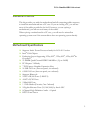
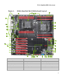
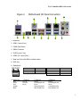
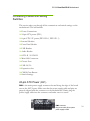
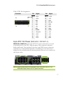
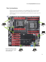
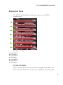
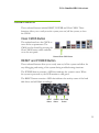
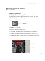
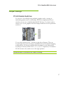
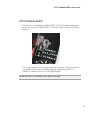
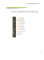
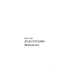
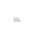
User Guide EVGA Classified SR-X 1 EVGA Classified SR-X Motherboard Table of Contents Before You Begin… ............................................................................................... 4 Motherboard Specifications .................................................................................... 5 Unpacking and Parts Descriptions ...................................................................... 6-7 Equipment ......................................................................................................... 8-9 Hardware Installation .......................................................................................... 10 Installing the CPU .......................................................................................... 11-12 Installing the Cooling Device ................................................................................ 13 Installing DIMMs ................................................................................................. 13 Installing the Motherboard................................................................................... 14 Motherboard I/O Panel ........................................................................................ 14 Securing the Motherboard into the Chassis ........................................................... 15 Connecting Cables and Setting Switches ............................................................... 16 24-pin ATX Power (PW1) ..................................................................................... 16 8-pin ATX 12V Power (PW12-P0-1, PW12-P1-1) .................................................... 17 Connecting Serial ATA Cables .............................................................................. 18 Front Panel Header ............................................................................................. 19 USB Headers ...................................................................................................... 20 Audio Header ...................................................................................................... 21 Fan Connections ................................................................................................. 22 Expansion Slots................................................................................................... 23 PCI-E x16 Slots ................................................................................................... 24 2 EVGA Classified SR-X Motherboard Onboard Buttons ................................................................................................. 25 Post Port Debug LED and LED Status Indicators .................................................... 26 PCIE-E Disable Swtiches ...................................................................................... 27 CPU1 Disable Swtiches ........................................................................................ 28 DIMM Disable Swtiches ....................................................................................... 29 Voltage Measure Point ......................................................................................... 30 Installing Drivers and Software ........................................................................... 31 POST Codes ................................................................................................... 32-33 EVGA Glossary of Terms ................................................................................. 34-36 Compliance Information ...................................................................................... 37 3 EVGA Classified SR-X Motherboard Before You Begin… Thank you for purchasing the EVGA Classified SR-X Motherboard. This is the premier dual socket enthusiast class motherboard. With this purchase you not only receive the best dual Xeon® motherboard built for the enthusiast, by the enthusiast, you also receive our industry leading 24/7 technical support. If you ever have any issues we are here to support you and your purchase for the life of the product. 4 EVGA Classified SR-X Motherboard Intentions of the Kit This kit provides you with the motherboard and all connecting cables necessary to install the motherboard into a PC case. If you are building a PC, you will use most of the cables provided in the kit. If however, you are replacing a motherboard, you will not need many of the cables. When replacing a motherboard in a PC case, you will need to reinstall an operating system even if the current drives have an operating system already. Motherboard Specifications Supports Intel® Xeon® Processor family for LGA-2011 socket Intel® C606 Chipset Enthusiast Layout Supporting 2-Way SLI® , 3-Way SLI® , 4-Way SLI® & CrossfireX™ 12 DIMM Quad-Channel DDR3 1600MHz+ (Up to 96GB) PCI Express 3.0 Ready 7 PCI Express Graphics Expansion Slots 10 USB 2.0 Ports (four rear panel, six onboard) 6 USB 3.0 Ports (four rear panel, two onboard) Supports Bluetooth 2 SATA III/6G Ports (2-ESATA) 4 SATA II/3G Ports 2 Mini SAS Ports 1 1394b Header (Firewire, One Onboard) 2 Gigabit Ethernet Ports (10/100/1000) by Intel® NIC 8 Channel High Definition Audio + Optical HPTX Form Factor 5 EVGA Classified SR-X Motherboard Unpacking and Parts Descriptions Unpacking The EVGA Classified SR-X motherboard comes with all the necessary cables for adding a motherboard to a new chassis. Be sure to inspect each piece of equipment shipped in the packing box. If anything is missing or damaged, contact your reseller. Equipment The following accessories are included with EVGA Classified - motherboard. The EVGA Classified SR-X Motherboard This motherboard contains the Intel® C606 chipset and is SLI® ready for 2-way, Quad, 3-way, 3-way SLI® w/ PhysX and 4-way SLI® configurations. Visual Guide Helps to quickly and visually guide you through the hardware installation of the motherboard. 6 EVGA Classified SR-X Motherboard I/O Shield Installs in the system case to block radio frequency transmissions, protect internal components from dust, foreign objects, and aids in proper airflow within the chassis. 3 - 2-Port SATA Power Cables Allows a Molex power connector to adapt to a SATA power connector. 1 - 4-Port USB 2.0 Bracket Provides four (4) additional USB 2.0 ports on the rear of the case. 1 - 2-Port USB 3.0 Bracket Provides two (2) additional USB 3.0 ports on the rear of the case. 6 - SATA Data Cables Used to support the Serial ATA protocol and each one connects to a single port on the motherboard. 1 - 2-Way SLI® Bridge Bridges two (2) graphic cards together which allows for 2-Way SLI® . 1 – 3-Way SLI® Bridge Bridges three (3) graphic cards together which allows for 3-Way SLI® . 1 – 4-Way SLI® Bridge Bridges four (4) graphic cards together which allows for 4-Way SLI® . (on select card models) 1 - Installation CD Contains drivers and software needed to setup the motherboard. 7 EVGA Classified SR-X Motherboard Figure 1. EVGA Classified SR-X Motherboard Layout 2 4 16 26 1 7 4 25 22 23 23 22 7 15 7 6 24 10 21 13 8 9 7 3 20 5 14 11 12 7 19 18 17 1. Primary CPU socket 10. Serial-ATA (SATA) connectors 19. Reset button 2. Secondary CPU socket 11. USB 3.0 header 20. PC Speaker 3. 1394B header 12. Front panel connector 21. PCI-E 3.0 slots 4. CPU Fan headers 13. Debug LED Display 22. 8-pin ATX_12V power connector 5. Intel® C606 Chipset 14. USB headers 23. 6 Pin CPU power (optional) 6. 24-pin ATX power connector 15. 6 Pin power for PCI-E slots 24. Front panel Audio connector 7. Fan headers 16. EZ voltage read points 25. Back panel connectors (Figure 2) 8. PCI-E/DIMM disable switches 17. CMOS clear button 26. CPU1 disable switch 9. Mini-SAS connectors 18. Power button 8 EVGA Classified SR-X Motherboard Figure 2. Motherboard I/O Panel Connectors 8 1 2 4 3 2 5 7 7 6 6 10 9 1. Bluetooth 2. USB 2.0 ports (Four) 3. CMOS Clear Button 4. EVBot Connector 5. E-SATA ports (Two) 6. USB 3.0/2.0 ports (Four) 7. Dual Lan Ports with LEDs to indicate status 8. PS/2 Port 9. Optical port Activity LED Status Description Speed/Link LED Status Description Off No data transmission Yellow 1000 Mbps data rate Data transmission Green 100 Mbps data rate Off 10 Mbps data rate Blinking (Green) 10. Audio Port Blue Green Pink Orange Black 2-Channel Line-In Line-Out Mic In 6-Channel Line-In Front Speaker Out Mic In Center/Subwoofer Rear Speaker Out 8-Channel________ Line-In Front Speaker Out Mic In Center/Subwoofer Rear Speaker Out 9 EVGA Classified SR-X Motherboard Hardware Installation This section will guide you through the installation of the motherboard. The topics covered in this section are: Preparing the motherboard Installing the CPUs Installing the CPU fans Installing the memory Installing the motherboard Connecting cables Safety Instructions To reduce the risk of fire, electric shock, and injury, always follow basic safety precautions. Remember to remove power from your computer by disconnecting the AC main source before removing or installing any equipment from/to the computer chassis. 10 EVGA Classified SR-X Motherboard Preparing the Motherboard Installing the CPU Be very careful when handling the CPU. Hold the processor only by the edges and do not touch the bottom of the processor. Use the following procedure to install the CPU onto the motherboard. Please ensure that with single processor usage you are using CPU socket 0 and the adjacent ram slots. Unhook the left socket lever by pushing down and away from the socket. Unhook the right socket lever by pushing down and away from the socket. Gently press the left socket lever and the load plate will lift from the socket. Open the load plate and make sure not to damage any of the pins inside of the socket. Note: After removing the CPU socket cover, it is recommended to store it in case you ever need to transport your motherboard. If you ever remove the CPU, it is highly recommended to reinstall the socket cover. 11 EVGA Classified SR-X Motherboard Align the notches on the CPU to the notches in the socket. Lower the processor straight down into the socket. Note: Make sure the CPU is fully seated and level in the socket. Lower the load plate so it is resting on the CPU. Press the right socket lever down to lock into place. Carefully lock the lever back into place. Repeat this process for the secondary CPU. 12 EVGA Classified SR-X Motherboard Installing the Cooling Device There are many different cooling devices that can be used with this motherboard. Follow the instructions that came with your cooling assembly. Installing DIMMs Your new motherboard has twelve (12) 240-pin slots for DDR3 DIMMs (ECC or Non ECC). These slots support 1GB, 2GB, 4GB and 8GB DDR3 technology. There must be at least one DIMM slot populated in each red bank to ensure normal operation. Use the following recommendations for installing DIMMs. Always start by populating the red slots first, it is recommended to mirror the memory from CPU 0 to CPU 1. If only using CPU 0, do not use the slots for CPU 1. Note that there is only one gap near the center of the DIMM slot. This slot matches the slot on the DIMM to ensure the component is installed properly. 1. Unlock a DIMM slot by pressing the module clips outward. 13 EVGA Classified SR-X Motherboard 2. Align the memory module to the DIMM slot, and insert the module vertically into the DIMM slot. The plastic clips at both sides of the DIMM slot automatically lock the DIMM into the connector. Installing the Motherboard The sequence of installing the motherboard into the chassis depends on the chassis you are using and if you are replacing an existing motherboard or working with an empty chassis. Determine if it would be easier to make all the connections prior to this step or to secure the motherboard and then make all the connections. It is normally easier to secure the motherboard first. Use the following procedure to install the I/O shield and secure the motherboard into the chassis. Be sure that the CPU fan assembly has enough clearance for the chassis covers to lock into place and for the expansion cards. Also make sure the CPU Fan assembly is aligned with the vents on the covers. Installing the I/O Shield The motherboard kit comes with an I/O shield that is used to block radio frequency transmissions, protects internal components from dust and foreign objects, and promotes correct airflow within the chassis. Before installing the motherboard, install the I/O shield from the inside of the chassis. Press the I/O shield into place and make sure it fits securely. If the I/O shield does not fit into the chassis, you would need to obtain the proper size from the chassis supplier. 14 EVGA Classified SR-X Motherboard Securing the Motherboard into the Chassis Most computer chassis have a base with mounting studs or spacers to allow the motherboard to be secured to the chassis and help to prevent short circuits. If there are studs that do not align with a mounting hole on the motherboard, it is recommended that you remove that stud to prevent the possibility of a short circuit. In most cases, it is recommended to secure the motherboard using a minimum of thirteen (13) spacers. 1. Carefully place the motherboard onto the studs/spacers located inside the chassis. 2. Align the mounting holes with the studs/spacers. 3. Align the connectors to the I/O shield. 4. Ensure that the fan assembly is aligned with the chassis vents according to the fan assembly instruction. 5. Secure the motherboard with a minimum of thirteen screws. 15 EVGA Classified SR-X Motherboard Connecting Cables and Setting Switches This section takes you through all the connections and switch settings on the motherboard. This will include: Power Connections 24-pin ATX power (PW1) 8-pin ATX 12V power (PW12-P0-1, PW12-P1-1) Internal Headers Front Panel Header USB Headers Audio Header SATA II / SATA III Mini-SAS Connectors Chassis Fans USB 2.0/3.0 Expansion slots CMOS Clear Button Switch Settings 24-pin ATX Power (PW1) is the main power supply connector located along the edge of the board next to the SATA ports. Make sure that the power supply cable and pins are properly aligned with the connector on the motherboard. Firmly plug the power supply cable into the connector and make sure it is secure. PW1 PW1 connector Plug power cable from system power supply to PW1 16 EVGA Classified SR-X Motherboard Table 1. PW1 Pin Assignments Connector 24 12 Pin Signal Pin Signal 1 Board edge +3.3V 13 +3.3V 2 +3.3V 14 -12V 3 GND 15 GND 4 +5V 16 PS_ON 5 GND 17 GND 6 +5V 18 GND 7 GND 19 GND 8 PWROK 20 RSVD 9 +5V_AUX 21 +5V 10 +12V 22 +5V 11 +12V 23 +5V 12 +3.3V 24 GND 13 1 8-pin ATX 12V Power (PW12-P0-1, PW12-P1-1) PW12-P0-1, PW12-P1-1, the 8-pin ATX 12V power connections, are used to provide power to the CPU. Align the pins to the connectors and press firmly until seated. You can plug in the extra 6 pin PCI-E power connectors (optional) if you need them for extreme overclocking. It is not necessary or required as the motherboard will function perfectly with just one connector in each 8 pin socket. Before installing these plugs be ensure that the 8-pin connector is an ATX 12V differential output, and not a PCI-E power connector. 17 EVGA Classified SR-X Motherboard Connecting Serial ATA Cables The Serial ATA II connector is used to connect a Serial ATA II device to the motherboard. These connectors support the thin Serial ATA II cables for primary storage devices. The Serial ATA II interface allows up to 300MB/s data transfer rate. The two (2) Red ports are SATA 6Gbps spec and support transfer speeds of up to 600MB/s. SATA II drives are compatible but will not see the enhanced SATA 6Gbps performance. There are six (6) internal Serial ATA connectors and two (2) E-SATA on this motherboard. Connection points SATA0 – SATA1 are SATA 6GPS and are controlled by the Intel® Chipset. SATA 2 – SATA 5 are SATA 3GPS and are controller by the Intel® Chipset. Connection points ESATA 1 – ESATA 2 are SATA 6Gbps spec and are controlled by the Marvell 9182 chipset. There are also 2 SAS connectors that can break off into 8 SATA II connections. RX+ TXRXTX+ GND GND GND SATA II 2-5 SATA III ports 0/1 18 EVGA Classified SR-X Motherboard Connecting Internal Headers Front Panel Header The front panel header on this motherboard is used to connect the following four cables. (see Table 2 for pin definitions): PWRLED Attach the front panel power LED cable to these two pins of the connector. The Power LED indicates the system’s status. When the system is turned on, the LED will be on. When the system is turned off or in S3 status, the LED will be off. When the system is in S1 or S4 status, the LED will be on. PWRSW Attach the power button cable from the case to these two pins. Pressing the power button on the front panel turns the system on and off. Table 2.Front Panel Header Pins Pin No Connect 1 3 2 4 5 7 6 8 9 HD_PWR HD Active PWR LED STBY LED Ground RST BTN PWR BTN Ground +5V Empty 10 Empty HD_LED HD_LED Attach the hard disk drive indicator LED cable to these two pins. The HDD indicator LED indicates the activity status of the hard disks. RESET Attach the Reset switch cable from the front panel of the case to these two pins. The system restarts when the RESET switch is pressed. Signal PWRLED RESET PWRSW 19 EVGA Classified SR-X Motherboard USB Headers This motherboard contains four (4) USB 2.0 ports that are exposed on the back panel of the chassis. It also supports four (4) USB 3.0 ports on the back panel which can operate at USB 2.0 or USB 3.0 specifications. The motherboard also contains three 10-pin onboard header connections that can be used to connect an optional external bracket containing six (6) USB 2.0 ports. It also contains one 19-pin onboard header that can be used to connect an optional external bracket containing (2) USB 3.0 ports that are backwards compatible with USB 2.0. 1. Secure the bracket to either the front or rear panel of your chassis. 2. Connect the end of the USB cable to the USB 2.0/3.0 headers on the motherboard. Table 3. USB 2.0 Header Pins Connector USB 2.0 Header Connector Pin 1 Signal 5V_DUAL 3 D- 5 D+ 7 GND 9 Pin 2 Empty Signal 5V_DUAL 4 D- 6 D+ 8 GND 10 No Connect 20 EVGA Classified SR-X Motherboard Audio Header The audio connector supports HD audio standard and provides two kinds of audio output choices: The Front Audio & the Rear Audio. The front Audio supports re-tasking function. Table 4. Front Audio Header Connector Front Audio Connector 10 8 6 4 2 9 7 5 3 1 Pin 1 Signal PORT1_L 2 AUD_GND 3 PORT1_R 4 PRECENCE_J 5 PORT2_R 6 SENSE1_RETURN 7 SENSE_SEND 8 Empty 9 PORT2_L 10 SENSE2_RETURN 21 EVGA Classified SR-X Motherboard Fan Connections There are seven fan connections on the motherboard. The fan speed can be detected and viewed on select ports in the PC Health Status section of the CMOS Setup. The fans are automatically turned off after the system enters S3, S4 or S5 mode. Note: the CPU fan cable can be either a 3-pin or a 4-pin connector. Connect a 3-pin connector to pins 1, 2, and 3 on the CPU fan header. 22 EVGA Classified SR-X Motherboard Expansion Slots The EVGA Classified SR-X motherboard contains seven (7) PCI-E expansion slots. 1 2 3 4 5 6 7 PCI-E Slot Listing 1 – PCI-E x16/8 slot 2 – PCI-E x8 slot 3 – PCI-E x16/8 slot 4 – PCI-E x8 slot 5 – PCI-E x16/8 slot 6 – PCI-E x4 slot 7 – PCI-E x8 slot PCI-E x16 Slots These seven PCI-E x16/x8 slots are reserved for graphics cards, and x1/x4 devices. The bandwidth of the x16 slot is up to 32GB/sec when using a PCI23 EVGA Classified SR-X Motherboard E 3.0 graphics card. The design of this motherboard supports up to Four PCI-E graphics cards using NVIDIA’s SLI® technology. When installing a PCI-E x16 card, be sure the retention clip snaps and locks the card into place. If the card is not seated properly, it could cause a short across the pins. Secure the card’s metal bracket to the chassis with the screw used to hold the blank cover. 24 EVGA Classified SR-X Motherboard Onboard Buttons These onboard buttons include RESET, POWER and Clear CMOS. These functions allow you to easily reset the system, turn on/off the system, or clear the CMOS. Clear CMOS Button The motherboard uses the CMOS to store all the set parameters. The CMOS can be cleared by pressing the Clear CMOS button either onboard or on the rear panel. External Clear CMOS Button RESET and POWER Button These onboard buttons allow you to easily turn on/off the system and allow for easy debugging and testing of the system during troubleshooting situations. The POWER button contains a LED that indicates the system’s status. When the system is powered on, the LED remains a solid green. The RESET button contains a LED that indicates the activity status of the hard disk drives and will blink accordingly. RESET Button POWER Clear CMOS Button Button 25 EVGA Classified SR-X Motherboard 26Post Port Debug LED and LED Status Indicators Post Port Debug LED The Debug LED provides two-digit POST codes to show why the system may be failing to boot. It is useful during troubleshooting situations. This Debug LED will also display current CPU temperatures after the system has fully booted into the Operating System. Debug LED LED Status Indicators Theses LEDs indicate the system’s status. STANDBY LED (White): When the system standby, the LED is on. POWER LED (Red): When the system is powered on, the LED is on. DIMM LED (Yellow): When the memory slot is functional, the LED is on. STANDBY LED POWER LED DIMM LED 26 EVGA Classified SR-X Motherboard Jumper Settings PCI-E Disable Switches For the ease of troubleshooting multiple graphics cards or testing an individual graphics card’s overclocking, EVGA has implemented seven switches you can use to disable individual PCI-E slots. You don’t need to remove any of your graphics cards but simply disable the slot the particular card is in. JPE1 JPE2 JPE3 JPE4 JPE5 JPE6 JPE7 You see the location of the 7 switches in the above diagram. They are located right above the reset button and BIOS selector. In default shipping configurations, all slots are enabled with the jumpers in the left position. From top to bottom, PCI-E slots 1, 2, 3, 4, 5, 6, 7 respectively. To disable a PCI-E slot move the switch over to the right position. Do this when the PC is turned off, NOT while it is running! 27 EVGA Classified SR-X Motherboard CPU1 Disable Switch For the ease of troubleshooting Dual CPUs, EVGA has implemented one switch you can use to disable CPU1. You don’t need to remove the CPU to disable it. You see the location of the switch in the above diagram. It is located at the top middle of the board. In default shipping configuration CPU 1 is enabled. To disable it move it to the right position. Do this when the PC is turned off, NOT while it is running! 28 EVGA Classified SR-X Motherboard DIMM Disable Switches For the ease of troubleshooting memory or testing individual slots, EVGA has implemented switches to disable any DIMM slot. To disable a DIMM slot move the switch to the right position. You see the location of the switch in the above diagram. It is located right above the reset and BIOS selector switch. In default shipping configuration all DIMM slots are enabled. Do this when the PC is turned off, NOT while it is running! 29 EVGA Classified SR-X Motherboard Voltage Measure Point The motherboard is equipped with thirteen voltage measure point pads. You can use a voltmeter or multimeter to measure the voltage at each pad. CPU 0 Vcore voltage CPU 0 VSA voltage CPU 1 DIMM1 voltage CPU 1 DIMM2 voltage CPU 1 IOH PLL voltage CPU 0 Vcore voltage CPU 0 VSA voltage CPU 0 DIMM1 voltage CPU 0 DIMM2 voltage CPU 0 IOH PLL voltage V1P1 voltage Ground 30 EVGA Classified SR-X Motherboard Installing Drivers and Software It is important to remember that before installing the driver CD that is shipped in the kit, you need to load your operating system. The motherboard supports Windows 7/Vista. The kit comes with a CD that contains utilities, drivers. The CD that has been shipped with your EVGA Classified SR-X motherboard contains the following software and drivers: Chipset Drivers Audio Drivers RAID Drivers LAN Drivers USB 3.0 Drivers Bluetooth Drivers EVGA E-LEET Marvell E-SATA 6Gbps Drivers Adobe Acrobat Reader User Manual Windows XP/Vista/Win7 Drivers Install 1. Insert the EVGA Classified SR-X installation CD for the motherboard included in the kit. 2. The CD will autorun. Install the drivers and utilities listed on the install screen. If the CD does not run, go to My Computer and click on the CD to open. 31 EVGA Classified SR-X Motherboard AMI POST Code Code Description 03 Initialize BIOS. 04 Check Battery Power and CMOS 05 Initialize interrupt controlling hardware/vector table 06 Initialize system timer 07 Fixes CPU POST interface calling pointer 08 Primary initialization of CPU C0 Secondary initialization of CPU C1 Set up boot strap processor information C2 Set up boot strap processor for POST C5 Enumerate and set up application processors C6 Re-enable cache for boot strap processor C7 Early CPU initialization exit 0A Initialize keyboard controller 0B Detect Mouse 0C Detect Keyboard 0E Test input devices 13 Early POST initialization of chipset registers 20 Relocate System Management interrupt vector 24 Uncompress and initialize BIOS module 2A Initialize devices primary 2C Initialize devices secondary 2E Initialize output devices 31 Allocate memory for ADM module 33 Initialize silent boot module 37 Display sign-on message 38 Initialize USB controller 39 Initialize DMAC-1 & DMAC-2 32 EVGA Classified SR-X Motherboard Code Description 3A Initialize real time clock 3B Test system memory 3C Initialization of chipset registers 40 Detect coprocessor 52 Update CMOS memory size 60 Initialize NUM-LOCK 75 Initialize Int-13 78 Initialize IPL devices 7C Generate and write contents of ESCD 84 Log errors encountered 85 Display errors, if no display check monitor/graphics card 87 Execute BIOS setup if needed or requested 8C Late POST initialization of chipset registers 8D Build ACPI tables 8E Program peripheral parameters 90 Initialize system management interrupt A1 Prepare for system boot A2 Initialize IRQ routing table A4 Display boot option popup A7 Display system configuration screen A9 Wait for user input at configuration display AA Uninstall POST vector AB Prepare BBS for Int 19 boot AC End of POST initialization B1 Save system context for ACPI 00 Pass control to OS (will vary) Show CPU Temp (if enabled) 33 EVGA Classified SR-X Motherboard EVGA Glossary of Terms AC – Alternating Current ACPI - Advanced Configuration and Power Interface AFR – Alternate Frame Rendering APIC - Advanced Programmable Interrupt Controller ACPI – Advanced Configuration and Power Interface BCLK – Base Clock (or operating frequency of base system bus) BIOS - Basic Input Output System CD-ROM - Compact Disc Read-Only Memory CMOS - Complementary Metal-Oxide Semiconductor CPU – Central Processing Unit DDR - Double Data Rate DIMM - Dual In-line Memory Module DMI – Direct Memory Interface DRAM - Dynamic random access memory DVD - Digital Versatile Disc DVI – Digital Video Interface FDC - Floppy Disk Controller FSB – Front Side Bus FTW – For the Win! GHz – Gigahertz GPU – Graphics Processing Unit HDD - Hard Disk Drive HDMI - High-Definition Multimedia Interface HDR – High Dynamic Range Lighting HPET - High Precision Event Timer 34 EVGA Classified SR-X Motherboard HT – Hyper-Threading HSF - Heat Sink Fan I/O - Input/Output IDE - Integrated Drive Electronics IEEE - Institute of Electrical and Electronics Engineers IGP - Integrated Graphics Processors IMC – Integrated memory controller IRQ - Interrupt Request JBOD - Just a Bunch of Disks JEDEC - Joint Electron Device Engineering Council LAN - Local Area Network LCD - Liquid Crystal Display LGA – Land Grid Array LN2 – Liquid Nitrogen Cooling MAC - Media Access Control MCP - Media and Communications Processor Intel ME – Intel Management Engine MHz – Megahertz MMIO – Memory Mapped I/O NB - Northbridge NCQ - Native Command Queuing NIC - Network Interface Card NTFS - New Technology File System OEM - Original Equipment Manufacturer PATA - Parallel Advanced Technology Attachment EVGA X79 Motherboard PCB - Printed Circuit Board PCH – Platform Controller Hub PCI - Peripheral Component Interconnect PCI-E - Peripheral Component Interconnect Express PCI-X - Peripheral Component Interconnect Extended PLL – Phase Locked Loop 35 EVGA Classified SR-X Motherboard POST – Power on Self Test PWM – Pulse Width Modulation QDR - Quad Data Rate QPI – Quick Path Interconnect RAID - Redundant Array of Inexpensive Disks RAM – Random Access Memory ROM – Read Only Memory RGB - Red Green Blue SATA - Serial Advanced Technology Attachment SAS – Serial Attached SCSI SB - Southbridge SCSI - Small Computer System Interface SFR – Split Frame Rendering SLI - Scalable Link Interface SMP – Symmetric Multiprocessing SPD - Serial Presence Detect SPDIF - Sony/Philips Digital Interconnect Format SPP - System Platform Processors SSD – Solid State Drive TCP/IP - Transmission Control Protocol/Internet Protocol USB - Universal Serial Bus VDroop - VCore Voltage Drop VGA - Video Graphics Array VREG – Voltage Regulator 1337 – This is reserved for the EVGA Elite! 36 EVGA Classified SR-X Motherboard Compliance Information FCC Compliance Information This device complies with FCC Rules Part 15. Operation is subject to the following two conditions: (1) This device may not cause harmful interference, and (2) this device must accept any interference received, including interference that may cause undesired operation. This equipment has been tested and found to comply with the limits for a Class B digital device, pursuant to Part 15 of the FCC Rules. These limits are designed to provide reasonable protection against harmful interference in a residential installation. This equipment generates, uses and can radiate radio frequency energy and, if not installed and used in accordance with the manufacturer’s instructions, may cause harmful interference to radio communications. However, there is no guarantee that interference will not occur in a particular installation. If this equipment does cause harmful interference to radio or television reception, which can be determined by turning the equipment off and on, the user is encouraged to try to correct the interference by one or more of the following measures: (1) Increase the separation between the equipment and signal source, or (2) connect the equipment to an outlet on a circuit different from that to which the signal source is connected. Consult the dealer or an experienced computer technician for help. The use of shielded cables for connection of peripheral devices to the PC systems is required to ensure compliance with FCC regulations. Changes or modifications to this unit not expressly approved by the party responsible for compliance could void the user’s authority to operate the equipment. CE Compliance Information Generic Radiation Interference Standard for Information Technology Equipment. (EN 55022: 2006, Class B), (EN 610003-2: 2006), (EN 61000-3-3: 1995 + A1: 2001 + A2: 2005). Warning: This is a Class B product. In a domestic environment this product may cause radio interference in which case the user may be required to take adequate measure. Generic Immunity Standard for Information Technology Equipment. (EN 55024: 1998 + A1: 2001 + A2: 2003). Trademark & Copyright Information 2001-2012 EVGA Corp. EVGA, the EVGA logo and combinations thereof are trademarks of EVGA Corp. All brand names, company names, service marks, logos, and trademarks of the company, or its affiliates or licensors are trademarks or registered trademarks of the company or its subsidiaries, affiliates or licensors in the US and other countries. Other company, products and service names may be trademarks or service marks of others. EVGA reserves the right to terminate this license if there is a violation of its terms or default by the Original Purchaser. Upon termination, for any reason, all copies of Software and materials must be immediately returned to EVGA and the Original Purchaser shall be liable to EVGA.com CORP for any and all damages suffered as a result of the violation or default. Legal Information All material including but not limited to, text, data, design specifications, diagnostics, graphics, logos, reference boards, files, images, drawings, and software including this document and the software itself (together and separately) is owned, controlled by, licensed to, or used with permission by Company and is protected by copyright, trademark, and other intellectual property rights. All is being provided “as is”, EVGA Corporation makes no warranties, whether express or implied, statutory or otherwise with respect to the materials and expressly disclaims all implied warranties of noninfringement, merchantability, and fitness for a particular purpose. In no event shall the liability of EVGA Corporation for claims arising from the use of the materials by anyone exceed the original purchase price of the materials (or replacement of the materials at EVGA Corporation’s option). All information furnished is believed to be accurate and reliable. However, EVGA Corporation assumes no responsibility for the consequences of use of such information or for any infringement of patents or other rights of third parties that may result from its use, or use of the Software. No license is granted by implication or otherwise under any patent or patent rights of EVGA Corporation except as expressly provided herein. All specifications mentioned in this publication are subject to change without notice. 37