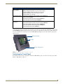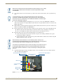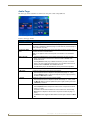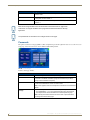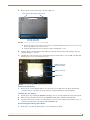
1
Operation/Reference Guide MVP-9000i 9" Modero® ViewPoint® Touch Panel with Intercom Touch Panels Last Revised: 3/26/2013 AMX Limited Warranty and Disclaimer This Limited Warranty and Disclaimer extends only to products purchased directly from AMX or an AMX Authorized Partner which include AMX Dealers, Distributors, VIP’s or other AMX authorized entity. AMX warrants its products to be free of defects in material and workmanship under normal use for three (3) years from the date of purchase, with the following exceptions: • Electroluminescent and LCD Control Panels are warranted for three (3) years, except for the display and touch overlay components are warranted for a period of one (1) year. • Disk drive mechanisms, pan/tilt heads, power supplies, and MX Series products are warranted for a period of one (1) year. • AMX lighting products are guaranteed to switch on and off any load that is properly connected to our lighting products, as long as the AMX lighting products are under warranty. AMX also guarantees the control of dimmable loads that are properly connected to our lighting products. The dimming performance or quality there of is not guaranteed, impart due to the random combinations of dimmers, lamps and ballasts or transformers. • AMX software is warranted for a period of ninety (90) days. • Batteries and incandescent lamps are not covered under the warranty. • AMX AutoPatch Epica, Modula, Modula Series4, Modula CatPro Series and 8Y-3000 product models will be free of defects in materials and manufacture at the time of sale and will remain in good working order for a period of three (3) years following the date of the original sales invoice from AMX. The three-year warranty period will be extended to the life of the product (Limited Lifetime Warranty) if the warranty card is filled out by the dealer and/or end user and returned to AMX so that AMX receives it within thirty (30) days of the installation of equipment but no later than six (6) months from original AMX sales invoice date. The life of the product extends until five (5) years after AMX ceases manufacturing the product model. The Limited Lifetime Warranty applies to products in their original installation only. If a product is moved to a different installation, the Limited Lifetime Warranty will no longer apply, and the product warranty will instead be the three (3) year Limited Warranty. All products returned to AMX require a Return Material Authorization (RMA) number. The RMA number is obtained from the AMX RMA Department. The RMA number must be clearly marked on the outside of each box. The RMA is valid for a 30-day period. After the 30-day period the RMA will be cancelled. Any shipments received not consistent with the RMA, or after the RMA is cancelled, will be refused. AMX is not responsible for products returned without a valid RMA number. AMX is not liable for any damages caused by its products or for the failure of its products to perform. This includes any lost profits, lost savings, incidental damages, or consequential damages. AMX is not liable for any claim made by a third party or by an AMX Authorized Partner for a third party. This Limited Warranty does not apply to (a) any AMX product that has been modified, altered or repaired by an unauthorized agent or improperly transported, stored, installed, used, or maintained; (b) damage caused by acts of nature, including flood, erosion, or earthquake; (c) damage caused by a sustained low or high voltage situation or by a low or high voltage disturbance, including brownouts, sags, spikes, or power outages; or (d) damage caused by war, vandalism, theft, depletion, or obsolescence. This limitation of liability applies whether damages are sought, or a claim is made, under this warranty or as a tort claim (including negligence and strict product liability), a contract claim, or any other claim. This limitation of liability cannot be waived or amended by any person. This limitation of liability will be effective even if AMX or an authorized representative of AMX has been advised of the possibility of any such damages. This limitation of liability, however, will not apply to claims for personal injury. Some states do not allow a limitation of how long an implied warranty last. Some states do not allow the limitation or exclusion of incidental or consequential damages for consumer products. In such states, the limitation or exclusion of the Limited Warranty may not apply. This Limited Warranty gives the owner specific legal rights. The owner may also have other rights that vary from state to state. The owner is advised to consult applicable state laws for full determination of rights. EXCEPT AS EXPRESSLY SET FORTH IN THIS WARRANTY, AMX MAKES NO OTHER WARRANTIES, EXPRESSED OR IMPLIED, INCLUDING ANY IMPLIED WARRANTIES OF MERCHANTABILITY OR FITNESS FOR A PARTICULAR PURPOSE. AMX EXPRESSLY DISCLAIMS ALL WARRANTIES NOT STATED IN THIS LIMITED WARRANTY. ANY IMPLIED WARRANTIES THAT MAY BE IMPOSED BY LAW ARE LIMITED TO THE TERMS OF THIS LIMITED WARRANTY. EXCEPT AS OTHERWISE LIMITED BY APPLICABLE LAW, AMX RESERVES THE RIGHT TO MODIFY OR DISCONTINUE DESIGNS, SPECIFICATIONS, WARRANTIES, PRICES, AND POLICIES WITHOUT NOTICE. AMX Software License and Warranty Agreement • LICENSE GRANT. AMX grants to Licensee the non-exclusive right to use the AMX Software in the manner described in this License. The AMX Software is licensed, not sold. This license does not grant Licensee the right to create derivative works of the AMX Software. The AMX Software consists of generally available programming and development software, product documentation, sample applications, tools and utilities, and miscellaneous technical information. Please refer to the README.TXT file on the compact disc or download for further information regarding the components of the AMX Software. The AMX Software is subject to restrictions on distribution described in this License Agreement. AMX Dealer, Distributor, VIP or other AMX authorized entity shall not, and shall not permit any other person to, disclose, display, loan, publish, transfer (whether by sale, assignment, exchange, gift, operation of law or otherwise), license, sublicense, copy, or otherwise disseminate the AMX Software. Licensee may not reverse engineer, decompile, or disassemble the AMX Software. • ACKNOWLEDGEMENT. You hereby acknowledge that you are an authorized AMX dealer, distributor, VIP or other AMX authorized entity in good standing and have the right to enter into and be bound by the terms of this Agreement. • INTELLECTUAL PROPERTY. The AMX Software is owned by AMX and is protected by United States copyright laws, patent laws, international treaty provisions, and/or state of Texas trade secret laws. Licensee may make copies of the AMX Software solely for backup or archival purposes. Licensee may not copy the written materials accompanying the AMX Software. • TERMINATION. AMX RESERVES THE RIGHT, IN ITS SOLE DISCRETION, TO TERMINATE THIS LICENSE FOR ANY REASON UPON WRITTEN NOTICE TO LICENSEE. In the event that AMX terminates this License, the Licensee shall return or destroy all originals and copies of the AMX Software to AMX and certify in writing that all originals and copies have been returned or destroyed. • PRE-RELEASE CODE. Portions of the AMX Software may, from time to time, as identified in the AMX Software, include PRERELEASE CODE and such code may not be at the level of performance, compatibility and functionality of the GA code. The PRE-RELEASE CODE may not operate correctly and may be substantially modified prior to final release or certain features may not be generally released. AMX is not obligated to make or support any PRE-RELEASE CODE. ALL PRE-RELEASE CODE IS PROVIDED "AS IS" WITH NO WARRANTIES. • LIMITED WARRANTY. AMX warrants that the AMX Software (other than pre-release code) will perform substantially in accordance with the accompanying written materials for a period of ninety (90) days from the date of receipt. AMX DISCLAIMS ALL OTHER WARRANTIES, EITHER EXPRESS OR IMPLIED, INCLUDING, BUT NOT LIMITED TO IMPLIED WARRANTIES OF MERCHANTABILITY AND FITNESS FOR A PARTICULAR PURPOSE, WITH REGARD TO THE AMX SOFTWARE. THIS LIMITED WARRANTY GIVES LICENSEE SPECIFIC LEGAL RIGHTS. Any supplements or updates to the AMX SOFTWARE, including without limitation, any (if any) service packs or hot fixes provided to Licensee after the expiration of the ninety (90) day Limited Warranty period are not covered by any warranty or condition, express, implied or statutory. • LICENSEE REMEDIES. AMX's entire liability and Licensee's exclusive remedy shall be repair or replacement of the AMX Software that does not meet AMX's Limited Warranty and which is returned to AMX in accordance with AMX's current return policy. This Limited Warranty is void if failure of the AMX Software has resulted from accident, abuse, or misapplication. Any replacement AMX Software will be warranted for the remainder of the original warranty period or thirty (30) days, whichever is longer. Outside the United States, these remedies may not available. NO LIABILITY FOR CONSEQUENTIAL DAMAGES. IN NO EVENT SHALL AMX BE LIABLE FOR ANY DAMAGES WHATSOEVER (INCLUDING, WITHOUT LIMITATION, DAMAGES FOR LOSS OF BUSINESS PROFITS, BUSINESS INTERRUPTION, LOSS OF BUSINESS INFORMATION, OR ANY OTHER PECUNIARY LOSS) ARISING OUT OF THE USE OF OR INABILITY TO USE THIS AMX SOFTWARE, EVEN IF AMX HAS BEEN ADVISED OF THE POSSIBILITY OF SUCH DAMAGES. BECAUSE SOME STATES/COUNTRIES DO NOT ALLOW THE EXCLUSION OR LIMITATION OF LIABILITY FOR CONSEQUENTIAL OR INCIDENTAL DAMAGES, THE ABOVE LIMITATION MAY NOT APPLY TO LICENSEE. • U.S. GOVERNMENT RESTRICTED RIGHTS. The AMX Software is provided with RESTRICTED RIGHTS. Use, duplication, or disclosure by the Government is subject to restrictions as set forth in subparagraph ©(1)(ii) of The Rights in Technical Data and Computer Software clause at DFARS 252.227-7013 or subparagraphs ©(1) and (2) of the Commercial Computer Software Restricted Rights at 48 CFR 52.227-19, as applicable. • SOFTWARE AND OTHER MATERIALS FROM AMX.COM MAY BE SUBJECT TO EXPORT CONTROL. The United States Export Control laws prohibit the export of certain technical data and software to certain territories. No software from this Site may be downloaded or exported (i) into (or to a national or resident of) Cuba, Iraq, Libya, North Korea, Iran, Syria, or any other country to which the United States has embargoed goods; or (ii) anyone on the United States Treasury Department's list of Specially Designated Nationals or the U.S. Commerce Department's Table of Deny Orders. AMX does not authorize the downloading or exporting of any software or technical data from this site to any jurisdiction prohibited by the United States Export Laws. This Agreement replaces and supersedes all previous AMX Software License Agreements and is governed by the laws of the State of Texas, and all disputes will be resolved in the courts in Collin County, Texas, USA. For any questions concerning this Agreement, or to contact AMX for any reason, please write: AMX License and Warranty Department, 3000 Research Drive, Richardson, TX 75082. FCC and IC Information This device complies with Part 15 of the FCC Rules and Industry Canada license-exempt RSS standard(s). Operation is subject to the following two conditions: (1) this device may not cause harmful interference, and (2) this device must accept any interference received; including interference that may cause undesired operation. Modifications to this product, unless expressly approved by AMX, could void the user’s authority to operate the equipment. Cet appareil est conforme avec Industrie Canada RSS standard exempts de licence (s). Son utilisation est soumise à Les deux conditions suivantes: (1) cet appareil ne peut pas provoquer d'interférences et (2) cet appareil doit accepter Toute interférence, y compris les interférences qui peuvent causer un mauvais fonctionnement du dispositif. This device complies with Health Canada's Safety Code 6 / IC RSS-210. The installer of this device should ensure that RF radiation is not emitted in excess of the Health Canada's requirement. Information can be obtained at: http://www.hc-sc.gc.ca/ewh-semt/pubs/radiation/radio_guidelignes_direct-eng.php Cet appareil est conforme avec Santé Canada Code de sécurité 6 / IC RSS-210. Le programme d'installation de cet appareil doit s'assurer que les rayonnements RF n'est pas émis au-delà de l'exigence de Santé Canada. Les informations peuvent être obtenues: http://www.hc-sc.gc.ca/ewhsemt/ pubs/radiation/radio_guide-lignes_direct-eng.php Federal Communications Commission (FCC) Statement This equipment has been tested and found to comply with the limits for a Class B digital device, pursuant to Part 15 of the FCC rules. These limits are designed to provide reasonable protection against harmful interference in a residential installation. This equipment generates, uses and can radiate radio frequency energy, and, if not installed and used in accordance with the instructions, may cause harmful interference to radio communications. However, there is no guarantee that interference will not occur in a particular installation. If this equipment does cause harmful interference to radio or television reception, which can be determined by turning the equipment off and on, the user is encouraged to try to correct the interference by one or more of the following measures: • Reorient or relocate the receiving antenna. • Increase the separation between the equipment and receiver. • Connect the equipment into an outlet on a circuit different from that to which the receiver is connected. • Consult the dealer or an experienced radio/TV technician for help. FCC RF Radiation Exposure Statement This product has been evaluated and found to comply with the limits established by the FCC, Industry Canada and other international standards for radio frequency exposure when used as described in this manual. The use of accessories not described may not ensure compliance with these limits. Indoor Use This device is intended for indoor use only. WiFi operation in the 5150-5250 MHz range is only for indoor usage to reduce potential for harmful interference to co-channel mobile satellite systems. Dans la gamme de fréquences 5150 - 5250MHz, cet appareil est exclusivement destiné à un usage en intérieur afin de réduire les risques potentiels d'interférences avec les systèmes de communications satellites partageant les mêmes canaux. Table of Contents Introduction ........................................................................................................1 Overview .................................................................................................................. 1 Common Application....................................................................................................... 1 Features .......................................................................................................................... 1 Memory .................................................................................................................... 4 Connector Locations ................................................................................................. 4 Basic Operation ........................................................................................................ 5 Powering on the MVP-9000i ..................................................................................... 5 Intercom Microphone ............................................................................................... 5 Stylus ........................................................................................................................ 5 Kick Stand................................................................................................................. 5 Audio/Video Capabilities .......................................................................................... 5 Power Management.................................................................................................. 5 Cleaning the Touch Overlay and Case ...................................................................... 6 Picture View.............................................................................................................. 7 Preview Mode and Normal Mode ................................................................................... 8 Picture View Send Command .......................................................................................... 8 Seamless Wireless to Wired Swap ............................................................................ 9 Accessories .......................................................................................................11 Table Docking Station............................................................................................. 11 Powering the MVP-TDS-9.............................................................................................. 12 Recharging.............................................................................................................. 13 Using the USB ports ...................................................................................................... 13 Undocking the Touch Panel........................................................................................... 13 Cleaning the MVP-TDS-9 ............................................................................................... 13 Wall Docking Station .............................................................................................. 14 Unlocking the Touch Panel ..................................................................................... 15 Recharging.............................................................................................................. 16 A Note About Wall and Rack Installation................................................................ 17 Installation Recommendations ...................................................................................... 17 Installing the MVP-WDS-9....................................................................................... 18 Installing the Wall Docking Station and Plastic Back Box .............................................. 18 Installing the Optional Metal Rough-In Box ............................................................ 20 Pre-Wall Installation of the CB-MVP-WDS9 ................................................................... 20 Other MVP-WDS-9 installations .................................................................................... 21 Undocking from the MVP-TDS-9 or MVP-WDS-9 .................................................... 22 Configuring Communication .............................................................................25 Overview ................................................................................................................ 25 MVP-9000i 9" Modero® ViewPoint® Touch Panel with Intercom 1 IR Communication ................................................................................................... 26 Modero Setup and System Settings ....................................................................... 26 Accessing the Setup and Protected Setup Pages.......................................................... 26 Setting the Panel’s Device Number............................................................................... 27 Wireless Settings - Wireless Access Overview ........................................................ 27 DHCP............................................................................................................................. 27 Dynamic Frequency Selection (DFS) .............................................................................. 27 Configuring Wireless Network Access .................................................................... 29 Step 1: Configure the Device’s WiFi Settings ......................................................... 29 Wireless communication using a DHCP Address ........................................................... 29 Wireless Communication Using a Static IP Address....................................................... 30 Using the Wireless Site Survey Tool .............................................................................. 30 Step 2: Configure the Card’s Wireless Security Settings ........................................ 32 Configuring the Device’s Wireless Card for Secured Access to a WPA-PSK-Secured AP 32 Step 3: Choose a Master Connection Mode ........................................................... 32 Ethernet Over USB ................................................................................................. 33 Touch Panel Setup......................................................................................................... 33 Configure a Virtual NetLinx Master using NetLinx Studio ............................................. 35 Ethernet ........................................................................................................................ 37 Master Connection to a Virtual Master via Ethernet ..................................................... 37 Using G4 Web Control to Interact with a G4 Panel ................................................ 39 Using the NetLinx Master To Control the G4 Panel................................................ 40 Setup Pages ......................................................................................................43 Overview ................................................................................................................ 43 Accessing the Setup pages ..................................................................................... 43 Landscape and Portrait Mode Setup Pages ............................................................ 43 Setup Page ............................................................................................................. 43 Navigation Buttons........................................................................................................ 44 Display Page ........................................................................................................... 45 Audio Page ............................................................................................................. 46 WAV files - Supported Sample Rates ............................................................................ 47 Power Management Page....................................................................................... 47 Battery Conditioning ..................................................................................................... 48 Automatic Battery Conditioning.................................................................................... 49 Testing the Battery........................................................................................................ 50 Date/Time Page ...................................................................................................... 52 Panel Information Page........................................................................................... 54 Panel Information Page - Info ........................................................................................ 54 Panel Information Page - Config.................................................................................... 55 Panel Information Page - File ........................................................................................ 56 2 MVP-9000i 9" Modero® ViewPoint® Touch Panel with Intercom Panel Information Page - Project................................................................................... 57 Protected Setup Pages .....................................................................................59 System & Panel Options page ................................................................................ 60 Function Show Example ................................................................................................ 61 Security Settings ........................................................................................................... 62 Installing Firmware ........................................................................................................ 63 System Settings Page ............................................................................................. 64 System Settings - Master .............................................................................................. 64 System Settings - Wired ................................................................................................ 65 System Settings - WiFi .................................................................................................. 66 Security Modes ....................................................................................................... 68 Open ............................................................................................................................. 69 WEP .............................................................................................................................. 69 WPA-PSK....................................................................................................................... 71 EAP Security & Server Certificates - Overview ....................................................... 72 EAP-LEAP ...................................................................................................................... 72 EAP-FAST ...................................................................................................................... 74 EAP-PEAP...................................................................................................................... 76 EAP-TTLS....................................................................................................................... 77 EAP-TLS......................................................................................................................... 79 Client Certificate Configuration .................................................................................... 81 System Settings - USB ................................................................................................... 82 Calibrate Page ........................................................................................................ 82 G4 Web Control Settings Page............................................................................... 83 Passwords ............................................................................................................... 84 Panel Logs Page ..................................................................................................... 86 Cache Settings Page ............................................................................................... 86 Panel Statistics Page ............................................................................................... 88 Panel Statistics - ICSP .................................................................................................... 88 Panel Statistics - Blinks Tab ........................................................................................... 89 Panel Statistics - IP Tab ................................................................................................. 89 Panel Statistics - Wireless Tab ....................................................................................... 90 Connection Utility Page ................................................................................................ 90 SIP Settings Page.................................................................................................... 91 Upgrading Firmware ........................................................................................93 Overview ................................................................................................................ 93 Upgrading Firmware via USB stick or MicroSD card ............................................... 93 Upgrading from Previous Firmware........................................................................ 95 Upgrading Firmware Via NetLinx Studio ................................................................ 95 Step 3: Confirm and Upgrade the firmware via the USB port ....................................... 97 MVP-9000i 9" Modero® ViewPoint® Touch Panel with Intercom 3 A Special Note for Network Interface Connections ................................................ 99 Reverting the MVP-9000i to Factory Default Firmware ........................................ 101 Programming ..................................................................................................103 Overview .............................................................................................................. 103 Animated Transitions ............................................................................................ 103 ^AFP .................................................................................................................................... 104 Touch Gesture Recognition................................................................................... 104 Gesture Velocity.......................................................................................................... 105 Gesture Prioritization .................................................................................................. 105 Gesture VNC/Mouse Support...................................................................................... 105 Gesture Custom Event ................................................................................................ 105 Enabling or Disabling the Gesture Custom Event ....................................................... 106 ^GCE.................................................................................................................................... 106 Page Commands ................................................................................................... 107 @APG ................................................................................................................................... @CPG ................................................................................................................................... @DPG ................................................................................................................................... @PDR ................................................................................................................................... @PHE.................................................................................................................................... @PHP.................................................................................................................................... @PHT.................................................................................................................................... @PPA.................................................................................................................................... @PPF .................................................................................................................................... @PPG ................................................................................................................................... @PPK.................................................................................................................................... @PPM ................................................................................................................................... @PPN ................................................................................................................................... @PPT .................................................................................................................................... @PPX.................................................................................................................................... @PSE .................................................................................................................................... @PSP .................................................................................................................................... @PST .................................................................................................................................... PAGE.................................................................................................................................... PPOF .................................................................................................................................... PPOG ................................................................................................................................... PPON ................................................................................................................................... 107 107 107 107 107 108 108 108 108 109 109 109 109 110 110 110 110 110 110 111 111 111 Programming Numbers......................................................................................... 112 RGB Triplets and Names For Basic 88 Colors ............................................................. 112 Font Styles And ID Numbers ....................................................................................... 114 Border Styles And Programming Numbers ................................................................. 114 "^" Button Commands ......................................................................................... 116 ^ANI..................................................................................................................................... ^APF .................................................................................................................................... ^BAT .................................................................................................................................... ^BAU.................................................................................................................................... ^BCB .................................................................................................................................... ^BCF .................................................................................................................................... 4 116 116 117 117 117 118 MVP-9000i 9" Modero® ViewPoint® Touch Panel with Intercom ^BCT..................................................................................................................................... ^BDO.................................................................................................................................... ^BFB..................................................................................................................................... ^BIM ..................................................................................................................................... ^BLN .................................................................................................................................... ^BMC ................................................................................................................................... ^BMF .................................................................................................................................... ^BMI ..................................................................................................................................... ^BML .................................................................................................................................... ^BMP.................................................................................................................................... ^BNC .................................................................................................................................... ^BNN.................................................................................................................................... ^BNT .................................................................................................................................... ^BOP .................................................................................................................................... ^BOR .................................................................................................................................... ^BOS .................................................................................................................................... ^BPP..................................................................................................................................... ^BRD .................................................................................................................................... ^BSF ..................................................................................................................................... ^BSM .................................................................................................................................... ^BSO .................................................................................................................................... ^BSP ..................................................................................................................................... ^BVL ..................................................................................................................................... ^BVN .................................................................................................................................... ^BVP..................................................................................................................................... ^BVT..................................................................................................................................... ^BWW .................................................................................................................................. ^CPF..................................................................................................................................... ^DLD .................................................................................................................................... ^DPF..................................................................................................................................... ^ENA .................................................................................................................................... ^FON.................................................................................................................................... ^GDI ..................................................................................................................................... ^GIV ..................................................................................................................................... ^GLH .................................................................................................................................... ^GLL ..................................................................................................................................... ^GRD.................................................................................................................................... ^GRU .................................................................................................................................... ^GSC .................................................................................................................................... ^GSN .................................................................................................................................... ^ICO ..................................................................................................................................... ^IRM ..................................................................................................................................... ^JSB ..................................................................................................................................... ^JSI....................................................................................................................................... ^JST...................................................................................................................................... ^MBT .................................................................................................................................... ^MDC ................................................................................................................................... ^PIC...................................................................................................................................... ^SHO .................................................................................................................................... ^TEC..................................................................................................................................... ^TEF ..................................................................................................................................... ^TOP .................................................................................................................................... ^TXT ..................................................................................................................................... ^UNI ..................................................................................................................................... MVP-9000i 9" Modero® ViewPoint® Touch Panel with Intercom 118 118 119 119 119 120 121 123 123 123 124 124 124 124 125 125 125 125 126 126 126 126 126 127 127 127 127 127 127 128 128 128 129 129 129 129 129 130 130 130 130 131 131 131 132 132 132 132 132 133 133 133 133 134 5 ^WLD ................................................................................................................................... 134 Miscellaneous MVP Strings.......................................................................................... 135 undock-<user> ..................................................................................................................... UNDOCKED ......................................................................................................................... SWAP ................................................................................................................................... dock ..................................................................................................................................... 135 135 135 135 MVP Panel Lock Passcode Commands ........................................................................ 135 ^LPC..................................................................................................................................... 135 ^LPR..................................................................................................................................... 135 ^LPS ..................................................................................................................................... 135 Text Effects Names ............................................................................................... 136 Button Query Commands ..................................................................................... 137 ?BCB .................................................................................................................................... ?BCF..................................................................................................................................... ?BCT..................................................................................................................................... ?BMP.................................................................................................................................... ?BOP .................................................................................................................................... ?BRD .................................................................................................................................... ?BWW .................................................................................................................................. ?FON.................................................................................................................................... ?ICO ..................................................................................................................................... ?JSB ..................................................................................................................................... ?JSI....................................................................................................................................... ?JST...................................................................................................................................... ?TEC..................................................................................................................................... ?TEF ..................................................................................................................................... ?TXT ..................................................................................................................................... 138 138 139 139 140 140 141 141 142 142 143 143 144 144 145 Panel Runtime Operations .................................................................................... 146 ABEEP .................................................................................................................................. ADBEEP................................................................................................................................ @AKB ................................................................................................................................... AKEYB.................................................................................................................................. AKEYP .................................................................................................................................. AKEYR.................................................................................................................................. @AKP ................................................................................................................................... @AKR ................................................................................................................................... BEEP..................................................................................................................................... BRIT...................................................................................................................................... @BRT .................................................................................................................................... DBEEP .................................................................................................................................. @EKP.................................................................................................................................... PKEYP .................................................................................................................................. @PKP.................................................................................................................................... SETUP .................................................................................................................................. SHUTDOWN......................................................................................................................... SLEEP ................................................................................................................................... @SOU ................................................................................................................................... @TKP .................................................................................................................................... TPAGEON ............................................................................................................................ TPAGEOFF ........................................................................................................................... @VKB ................................................................................................................................... WAKE................................................................................................................................... 6 146 146 146 146 146 146 147 147 147 147 147 147 147 148 148 148 148 148 148 149 149 149 149 149 MVP-9000i 9" Modero® ViewPoint® Touch Panel with Intercom Input Commands................................................................................................... 150 ^CAL..................................................................................................................................... 150 ^KPS..................................................................................................................................... 150 ^VKS..................................................................................................................................... 150 Embedded codes .................................................................................................. 151 Panel Setup Commands ........................................................................................ 152 @PWD................................................................................................................................... 152 ^PWD ................................................................................................................................... 152 Dynamic Image Commands................................................................................... 153 ^BBR..................................................................................................................................... 153 ^RAF..................................................................................................................................... 153 ^RFR ..................................................................................................................................... 153 ^RAF, ^RMF - Embedded Codes ................................................................................ 154 ^RMF .................................................................................................................................... 154 ^RSR ..................................................................................................................................... 154 Escape Sequences ....................................................................................................... 155 $DV....................................................................................................................................... $SY ....................................................................................................................................... $IP ........................................................................................................................................ $HN ...................................................................................................................................... $MC ...................................................................................................................................... $ID ........................................................................................................................................ $PX ....................................................................................................................................... $PY ....................................................................................................................................... $ST ....................................................................................................................................... $AC....................................................................................................................................... $AP ....................................................................................................................................... $CC....................................................................................................................................... $CP ....................................................................................................................................... $LC ....................................................................................................................................... $LP........................................................................................................................................ $BX ....................................................................................................................................... $BY ....................................................................................................................................... $BN ...................................................................................................................................... 155 155 155 155 155 155 155 155 155 155 155 155 155 155 155 155 155 155 Intercom Commands............................................................................................. 156 ^MODEL? ............................................................................................................................. ^ICS- ..................................................................................................................................... ^ICE'..................................................................................................................................... ^ICM-TALK ........................................................................................................................... ^ICM-LISTEN ........................................................................................................................ ^ICM-MICLEVEL ................................................................................................................... ^ICM-MUTEMIC.................................................................................................................... ^ICM-SPEAKERLEVEL........................................................................................................... 156 156 156 157 157 157 157 157 SIP Commands ...................................................................................................... 158 ^PHN-AUTOANSWER........................................................................................................... ^PHN-CALL........................................................................................................................... ^PHN-DECLINE .................................................................................................................... ^PHN-INCOMING................................................................................................................. ^PHN-LINESTATE ................................................................................................................. ^PHN-ANSWER .................................................................................................................... MVP-9000i 9" Modero® ViewPoint® Touch Panel with Intercom 158 158 158 158 158 159 7 ^PHN-AUTOANSWER .......................................................................................................... ^PHN-MSGWAITING............................................................................................................ ^PHN-PRIVACY .................................................................................................................... ^PHN-REDIAL ...................................................................................................................... ^PHN-TRANSFERRED .......................................................................................................... ?PHN-AUTOANSWER........................................................................................................... ^PHN-CALL .......................................................................................................................... ^PHN-DTMF......................................................................................................................... ^PHN-HANGUP.................................................................................................................... ^PHN-HOLD......................................................................................................................... ?PHN-LINESTATE ................................................................................................................. ^PHN-PRIVACY .................................................................................................................... ?PHN-PRIVACY..................................................................................................................... ^PHN-REDIAL ...................................................................................................................... ^PHN-SETUP-DTMFDURATION ........................................................................................... ^PHN-SETUP-DOMAIN ........................................................................................................ ^PHN-SETUP-ENABLE.......................................................................................................... ^PHN-SETUP-PASSWORD.................................................................................................... ^PHN-SETUP-PORT .............................................................................................................. ^PHN-SETUP-PROXYADDR.................................................................................................. ^PHN-SETUP-STUNADDR .................................................................................................... ^PHN-TRANSFER ................................................................................................................. ^PHN-SETUP-USERNAME .................................................................................................... 159 159 159 159 159 160 160 160 160 160 160 160 160 160 161 161 161 161 161 161 161 161 162 Battery Life and Replacement ........................................................................163 Overview .............................................................................................................. 163 IMPORTANT NOTES! ............................................................................................ 164 Power Management.............................................................................................. 164 Proper Battery Maintenance ................................................................................. 165 Battery Replacement ............................................................................................ 165 READ THESE INSTRUCTIONS FIRST!........................................................................... 165 Replacing the Battery ........................................................................................... 166 Remove the old battery .............................................................................................. 167 Installing the new battery............................................................................................ 167 Reconnecting the battery to the device ...................................................................... 167 Appendix A: Text Formatting .........................................................................169 Text Formatting Codes for Bargraphs/Joysticks................................................... 169 Text Area Input Masking....................................................................................... 170 Input mask character types ......................................................................................... 170 Input Mask Ranges ...................................................................................................... 171 Input mask next field characters.................................................................................. 171 Input mask operations................................................................................................. 171 Input mask literals ....................................................................................................... 171 Input mask output examples ....................................................................................... 172 URL Resources ...................................................................................................... 172 Special Escape Sequences ........................................................................................... 173 8 MVP-9000i 9" Modero® ViewPoint® Touch Panel with Intercom Complex Script Support ....................................................................................... 174 Appendix B: Wireless Technology ..................................................................175 Overview of Wireless Technology......................................................................... 175 Terminology.......................................................................................................... 176 802.1x ......................................................................................................................... 176 AES ............................................................................................................................. 176 CERTIFICATES (CA) ..................................................................................................... 176 MIC.............................................................................................................................. 176 TKIP............................................................................................................................. 176 WEP ............................................................................................................................ 176 WPA ............................................................................................................................ 176 WPA2 .......................................................................................................................... 177 EAP Authentication............................................................................................... 178 EAP Characteristics ..................................................................................................... 178 EAP Communication Overview.................................................................................... 179 Configuring Modero Firmware via the USB Port .................................................. 180 Step 1: Configure The Panel For a USB Connection Type ........................................... 180 Step 2: Prepare NetLinx Studio For Communication Via the USB Port ....................... 180 AMX Certificate Upload Utility ............................................................................. 181 Uploading a Certificate File .................................................................................. 181 Erasing All Certificates From the Touch Panel ............................................................ 182 Appendix C: Troubleshooting ........................................................................183 Overview .............................................................................................................. 183 Panel Doesn’t Respond To Touches ............................................................................ 183 Battery Will Not Hold Or Take A Charge .................................................................... 183 MVP-9000i Isn’t Appearing In The Online Tree Tab .................................................... 183 MVP Can’t Obtain a DHCP Address ............................................................................ 184 My AP Doesn’t Seem To Be Working .......................................................................... 184 NetLinx Studio Only Detects One Of My Connected Masters .................................... 184 Can’t Connect To a NetLinx Master ............................................................................ 184 Only One Modero Panel In My System Shows Up....................................................... 184 Panel Behaves Strangely After Downloading A Panel File Or Firmware ..................... 184 MVP-9000i 9" Modero® ViewPoint® Touch Panel with Intercom 9 10 MVP-9000i 9" Modero® ViewPoint® Touch Panel with Intercom Introduction Introduction Overview The MVP-9000i redefines touch panel control offering both wireless and wired functionality, new user interface capabilities like gestures and animated page transitions, a stunning 9" widescreen 24-bit color display, full digital duplex VoIP telephone or intercom interface and built-in 802.11a/b/g WiFi card with antenna diversity. The MVP-9000i switches seamlessly to wireless mode when removed from either the MVP-TDS-9 Table Docking Station or the MVPWDS-9 Wall Docking Station. Transfer touch panel pages, upgrade the firmware or display photo files using the USB or micro-SD card slot. Available in black (FG5967-01) and white (FG5967-02), the MVP-9000i also features a capacitive touch directional pad, 4 programmable buttons, and over 3 GB of usable flash memory. The MVP-9000i also supports 5 hours of continuous use to three days of standby time. The MVP-9000i is certified compatible with Cisco Compatible Extensions (CCX), Version 4. Microphone Touch screen Status LED Speaker grille FIG. 1 MVP-9000i-GB touch panel Common Application The MVP-9000i is ideal for a wide variety of residential and commercial control and automation applications where flexibility of docked with wired Ethernet or undocked with 802.11a/b/g functionality is desired. This is an option for extremely noisy wireless environments such as multiple dwelling units, as well as applications that require telephone/ intercom functionality. Features Available in your choice of black or white. Capacitive touch buttons provide simple (up/down) or sophisticated control (up/down, right/left, select). VoIP Intercom and SIP Telephone (requires AMX SIP Gateway) Ready. 802.11a/b/g WiFi for two-way network communications. Wireless communications remain secure using WPA, WPA2, EAP-PEAP, EAP-FAST, EAP-LEAP, EAP- TLS, and EAP-TTLS network security standards. Enhanced usability with microphone and speakers. Versatile placement options, including an integrated kickstand and the optional MVP-TDS-9 Table Docking Station and MVP-WDS-9 Wall Docking Station. MVP-9000i 9" Modero® ViewPoint® Touch Panel with Intercom 1 Introduction The MVP-9000i comes with an integrated rear “kickstand”, allowing it to be used and displayed away from a Docking Station (FIG. 2). It also comes with a pre-installed 802.11a/b/g wireless card. Stylus Capacitive touch directional pad Capacitive touch buttons (4) Kickstand MicroSD memory card slot Speaker Mini-USB port Docking Station interface connector DC power jack FIG. 2 MVP-9000i side view (with kickstand) MVP-9000i Specifications Models Available: • MVP-9000i-GB (Black - FG5967-01) • MVP-9000i-GW (White - FG5967-02) Dimensions (HWD): • 7.62” x 10.98” x 1.06" (19.35 cm x 27.89 cm x 2.69 cm) Weight: • 3.60 lbs (1.63 kg) Enclosure: MVP-9000i-GB: Black plastic with brushed metal retaining ring. MVP-9000i-GW: White plastic with brushed metal retaining ring. Memory: • 4GB internal microSD (3.1GB accessible to user) Power Requirements (Without Charging): • Constant current draw: 1.1 A @ 12 VDC • Startup current draw: 1.2 A @ 12 VDC • If panel is mounted onto a TDS or WDS, add 0.1 A to the above figures. NOTE: Please see the Power Management section on page 164 for additional information. Power Requirements (While Charging): Panel while charging battery: • Constant current draw: 2.0 A @ 12VDC • If panel is mounted onto a TDS or WDS, add 0.1 A to the above figures. Minimum Power Supply Required: • PS3.0 Power Supply (FG423-30) (included) Power Modes: • ON: All necessary modules are powered up and device remains online with the NetLinx Master. • PS-POE-AT High Power PoE Injector (FG423-81) through the Table Docking Station and Wall Docking Station • SLEEP: Only the backlight will be turned off after the user selectable time of inactivity has elapsed. Panel resumes the ON mode immediately after being touched. • STANDBY: Power to all components other than the touch screen is turned off after the user selectable time of inactivity has elapsed. Device will turn back on by touching the screen. Re-acquiring an AP connection may require up to 25 seconds. (Standby Mode does not apply if a USB or microSD card is connected to the device. For more information, please refer to the Picture View section on page 7.) • SHUTDOWN: Power to all peripherals and components is turned off. The system remains in this mode until it is restarted by applying power or touching the screen. Battery Duration: • On (continuous use): 5 hours; Standby: 3 days • 10 hours of normal use, in a combination of On, Sleep, Standby, and Shutdown. • 3 days of standby use 2 MVP-9000i 9" Modero® ViewPoint® Touch Panel with Intercom Introduction MVP-9000i Specifications (Cont.) Panel LCD Parameters: • Screen resolution: 800 x 480 pixels (HV) @ 60 Hz refresh rate • Aspect ratio: 16 x 9 • Brightness (luminance): 400 cd/m2 • Channel transparency: 8-bit Alpha blending • Contrast ratio: 900:1 max. • Display colors: 16.7M colors (24-bit color depth) • Dot/pixel pitch: 0.246 mm • Panel type: TFT Color Active-Matrix (IPS technology) • Viewing angles: Vertical: + 85° (up from center) and - 85° (down from center) Horizontal: + 85° (left from center) and - 85° (right from center) External Components Stylus Slot: Slot where the included stylus is stored, located on the left side of the device. MicroSD Card Slot: Slot for insertion of standard MicroSD memory cards. Mini-USB Connector: 5-pin Mini-USB connector used for audio output to USB headphones, programming, firmware updates, and touch panel file transfer between the PC and the target panel. Note: When connecting the panel to PC using a CC-USB (or compatible) cable, be sure to power the panel On before attempting to connect the USB cable from the PC to the mini-USB port on the panel. DC power port: 2.5 mm port to power the panel away from a Docking Station. Microphone: For use with the intercom feature and for calls using SIP. • Frequency: 20 to 160,000 Hz • S/N Ratio: More than 58 dB Speaker: • 4 Ohm • 2 Watts 300Hz cutoff frequency Audio Standards: • G.711 sound standard • 75dB SPL@1m IR Emitters: Transmit IR (transmit only) over 20 feet (6.10 m) from the panel. • IR emitters on G4 panels share the device address number of the panel. • Transmits AMX fixed frequencies at 38KHz and 455KHz and third-party user-programmable frequencies from 20KHz to 1.5MHz Certifications: • FCC Class B • CE • IC • VCCI • C-Tick • Operating/Storage Environment • Operating Temperature: 0° C (32° F) to 40° C (104° F) • Battery Charging Temperature: 0° C (32° F) to 30° C (86° F) • Operating & Battery Charging Humidity: 20% to 85% RH • Storage Temperature: -10° C (-14° F) to 60° C (140° F) • Storage Humidity: 5% - 85% RH Included Accessories: • MVP-9000i Installation Guide (93-5967-01) • PS3.0 Power Supply (FG423-30) • Stylus (pre-installed onto the left side of the unit) MVP-9000i 9" Modero® ViewPoint® Touch Panel with Intercom 3 Introduction MVP-9000i Specifications (Cont.) Other AMX Equipment: • MVP-TDS-9-GB Black Table Docking Station (FG5967-10) • MVP-TDS-9-GW White Table Docking Station (FG5967-11) • MVP-WDS-9-GB Black Wall Docking Station (FG5967-12) • MVP-WDS-9-GW White Wall Docking Station (FG5967-13) • CB-MVP-WDS9 Rough-In Box for Wall Docking Station (FG038-13) • CB-MVP-WBS9B Rough-In Box Back for Wall Docking Station (FG038-14) • MVP-STYLUS-52-XX Replacement Stylus, pack of 3 (Black: FG5966-21; White: FG5966-22) • CC-MINIUSB Mini USB to PC Cable Adapter (FG5967-20) • CSG-500 Gateway for 50 Users (FG2182-01) • CSG-544 Gateway for 50 Users, 4 analog phone input ports, 4 PSTN output ports (FG2182-02) • CSG-580 Gateway for 50 Users, 8 PSTN lines (FG2182-03) • PS-POE-AT High Power PoE Injector (FG423-81) • MicroSD card - 4GB (FG2116-81) • MicroSD card - 8GB (FG2116-82) • NXA-WAP1000 Smart Wireless Access Point (FG2255-51/53) This device complies with FCC Part 15 and Industry Canada RSS 210 subject to the following conditions: 1. This device must not cause harmful interference and 2. This device must accept all interference, including interference that interferes with the operation of this device. Memory The MVP-9000i comes with 4GB internal MicroSD memory, 3.1GB of which is accessible to the user. This memory may not be upgraded. Connector Locations With the unit facing you, the mini-USB port (for programming and downloading firmware and the DC power port are located on the lower left side of the device (FIG. 2). The connector for the Table Docking Station (please refer to the Table Docking Station section on page 11) is located on the bottom of the device. Although firmware upgrades can be conducted over a wireless Ethernet connection, transferring firmware KIT files over a wired LAN, USB data stick, or USB flash card is recommended, and only when the panel is connected to a power supply. If battery power is below 30 percent, and the touch panel is not connected to a power supply, the download will not be completed. In addition to its speaker, the MVP-9000i also utilizes its mini-USB port as a connector for standard headphones or headsets. These headphones must use a mini-USB plug or adaptor in order to utilize this feature. While standard input/output headsets may be used in lieu of headphones, the headset may only be used for output. While you may receive sound from the headset, its microphone will not function. Always use the MVP-9000i’s microphone for receiving sound. 4 MVP-9000i 9" Modero® ViewPoint® Touch Panel with Intercom Introduction Basic Operation The MVP-9000i is operated using its integral touchscreen, as well as the capacitive touch buttons on the left and the directional pad on the right side of the device (FIG. 1). If the device has gone into its Sleep or Standby Modes, a button press will awaken the device from Sleep Mode, but touching the screen is the only way to wake it from Standby Mode. The MVP-9000i device’s power use allows up to 72 hours of use between rechargings of its internal battery, but its battery charge lasts up to one month if the device goes into Shutdown Mode during that time. The device may be placed in its charging cradle at any time and operated within its cradle, making a wired Ethernet connection in the process. If shut down, the device will power up when placed in a Table Docking Station or Wall Docking Station, or when external power is applied via the PS3.0 Power Supply. If the device is in Standby Mode, the device will not turn on if its side buttons or directional pad are touched or the device is docked. Touching the screen is the only way to wake an MVP9000i from Standby Mode. Any wired connection intended for the device will be reconnected within approximately twenty seconds after the device is placed in a Table Docking Station or Wall Docking Station. Depending upon its settings, the device may be set to go into On Mode as soon as it is placed in the Docking Station. Powering on the MVP-9000i The MVP-9000i may be powered on by touching and holding the touchscreen. If the device was in Sleep Mode, it will automatically turn on when put into a Table or Wall Docking Station. Intercom Microphone The MVP-9000i contains a built-in microphone above the upper lefthand corner of the touch screen for video and audio conferencing capabilities. This microphone is concealed by the casing. Stylus The MVP-9000i comes with a unique touchscreen stylus that slides into a storage groove on the left side of the device when not in use. Replacement styluses may be ordered in a 3-pack (black, FG5966-21; white, FG5966-22) from www.amx.com. Kick Stand Since the MVP-9000i device is designed to be a unit used away from its docking station, it has an extendable “kickstand” on the back of the unit (FIG. 2). This may be opened by physically lifting the free end of the kick stand away from the device. The device may then be propped up on a flat surface and accessed in a normal fashion. Audio/Video Capabilities The MVP-9000i has the capability of displaying multiple JPEG and PNG files at one time. The device also supports streaming motion JPEG video (of the sort used by many IP and Web cameras) and hardware acceleration of Motion JPEG (previously configured in TPDesign4), as well as MP3 and WAV audio files. Power Management The MVP-9000i utilizes a dual voltage external power supply. It may be recharged through the supplied PS3.0 Power Supply (FG423-30), as well as through the MVP-TDS-9 Table Docking Station (FG5967-1X) or the MVP-WDS-9 Wall Docking Station (FG5967-1X). For more information, see the Accessories section on page 11 for details. MVP-9000i 9" Modero® ViewPoint® Touch Panel with Intercom 5 Introduction Charging Lithium Polymer batteries at high temperature will reduce the battery life. Industry guidelines dictate that batteries should not be charged at temperatures above 45° C (113° F). The temperature is determined by a combination of the ambient temperature where the panel is located, plus temperature increases normally occurring inside electronic devices containing batteries. AMX has implemented battery temperature monitoring features to maximize the rate of battery charging, while staying within industry temperature guidelines. Battery charge times will increase in installations where the room temperature is above 25° C (77° F), and may be temporarily suspended at room temperatures above 30° C (86° F). Battery charging will automatically resume once the temperature has fallen to appropriate levels. Minimizing the display backlight intensity and turning off the backlight during periods of non-use will also yield faster charge times. Although the MVP-9000i unit is equipped with a mini-USB port, the device cannot be powered through the USB port. The port is only used for uploading firmware. When not in active use, the MVP-9000i conserves battery life between chargings. Pressing the touch screen will return the device to its On Mode. For more information on the battery, see the Battery Life and Replacement section on page 163. Cleaning the Touch Overlay and Case Always use a clean cotton cloth and a spray bottle containing water or any standard ammonia-free glass cleaner can be used to clean the touch screen. Do NOT use alcohol-based cleaners, as alcohol-based cleaners can damage the device’s touch screen overlay. Do not directly spray the device: instead, spray the cloth to clean the touch screen overlay. Do NOT use an abrasive of any type to clean the MVP-9000i, as this may permanently damage or remove the device’s finish. 6 MVP-9000i 9" Modero® ViewPoint® Touch Panel with Intercom Introduction Picture View With Picture View, inserting a microSD memory card into the slot on the left side of the device, or connecting a USB drive via the mini-USB port (FIG. 2), allows the MVP-9000i to access JPEG images on that card and display them on the touchscreen (FIG. 3). Individual images may be accessed at any time, or the entire collection may be displayed for predetermined times. Picture View may be stopped at any time by removing the memory card or USB drive, and the MVP-9000i will return to its default display page. Picture View is disabled on the MVP-9000i by default, and must be enabled or disabled with the ^PIC Send Command. For more information, please refer to the ^PIC section on page 132. FIG. 3 Picture View display The maximum resolution of any image to be viewed in Picture View is 1280 x1024 pixels. Images larger than this should be reformatted before being added to a USB stick or MicroSD card. To start Picture View: 1. Connect a USB drive to the device or insert a microSD memory card into the microSD memory card slot. Picture View will automatically recognize all available images on the drive or memory card and start displaying them on the touchscreen. 2. When the images begin to display, touch any place on the touchscreen to open the configuration popup menu (FIG. 4). If no selection is made, this menu will remain in place for 15 seconds and then disappear. It may be accessed again by touching anywhere on the touchscreen. 3. On the leftmost red button, select between Rand (images display at random) and A-Z (images display in alphabetical order based on the name of the file). 4. The four blue buttons allow scrolling through saved images and the rate of display: The Previous button returns the display to the previously displayed image. The Stop button stops Page View and returns to the default panel page. The Pause/Resume button allows the display to stop on one particular image. Press it again to resume the display procession. The Next button moves the display to the next stored image. If the MPVP-9000i has not accessed all of the images available on a USB drive or memory card, Page View will display the last one uploaded to date. 5. On the rightmost red button, select the number of seconds a selected image will be displayed in Picture View. This may be selected between 5, 10, 15, 30, and 60 seconds. 6. The counter beneath the buttons displays the number of images currently uploaded by the MVP-9000i versus the number detected on the USB drive or microSD card. MVP-9000i 9" Modero® ViewPoint® Touch Panel with Intercom 7 Introduction Stop Random/ A-Z Counter Previous Timer Pause/ Resume Next FIG. 4 Picture View configuration popup menu Preview Mode and Normal Mode Picture View has two modes: Preview Mode and Normal Mode. Preview Mode allows the user to configure Picture View. Once an SD card or a USB drive containing images is inserted into the panel, the images will begin to display. Touching any place on the display will result in the configuration popup to slide from the bottom of the display. Picture View goes into its Normal Mode when the MVP-9000i goes into idle timeout while connected to a USB drive or memory card. Normal Mode displays images until the touchscreen or capacitive touch buttons are touched, or some other wakeup event is detected. When the device goes back into timeout, Normal Mode will return to displaying images until the USB drive or memory card are removed from the device. Picture View Send Command Picture View must be enabled or disabled with the ^PIC Send Command. For more information, please refer to the ^PIC section on page 132. All images must be in JPEG format. PNG and other image formats cannot be viewed through Picture View. 8 MVP-9000i 9" Modero® ViewPoint® Touch Panel with Intercom Introduction Seamless Wireless to Wired Swap The MVP-9000i's unique design allows for wireless as well as wired connectivity with the appropriate Table Docking Station or Wall Docking Station. To prevent offline events when transitioning between wired and wireless connectivity, the MVP-9000i allows for seamless swapping. For swapping to work correctly, the Wired (page 65) and WiFi (page 66) network settings must be configured properly. The current connection mode to the master is indicated by the connection icon in the upper right hand corner of the setup pages as well as in the Current Connection field in the System Settings page under the Master tab. Refer to the Miscellaneous MVP Strings section on page 135 for strings that are sent to the master when the panel is docked and undocked. Swapping between wired and wireless connections is only supported when the Master Mode is set to URL. For more information, please refer to the System Settings Page on page 64. To swap from a wireless connection to a wired one, simply place the panel in a Table Docking Station or Wall Docking Station. To swap from a wired connection to a wireless connection, you must first initiate an undock request. This can be done with the undock button on the Docking Station, or with the Undock Panel button in the System & Panel Options page (please refer to the System & Panel Options page on page 60). The swap will happen once a valid password is entered (if enabled). If the panel does not swap to the master immediately, a Confirmation Dialog popup will notify the user (FIG. 5). The user has the option to force an undock which will cause an offline event, or to cancel the undocking and remain in the dock. If the swap is completed sometime after the popup is displayed, the popup will disappear automatically. The popup will also disappear after a 15-second countdown. FIG. 5 “Attempting to Undock” popup window If an undock is initiated during a VoIP call or Dynamo session, pressing the Yes button ends all VoIP calls in progress and Dynamo sessions. After a successful swap from wired to wireless communication, if the panel is not removed from a Table Docking Station after 30 seconds, the dock will automatically lock the latch and swap back to wired communication. The firmware version of the Master controller must support swapping. If the user does not want to use the mechanical latch on the TDS or utilize the swapping feature, the Table Dock Latch button may be disabled or set to Off in the System & Panel Options page. If an undock is initiated during a VoIP call or a Dynamo session, a warning popup will be displayed (FIG. 6), allowing the user to proceed with the undock and disconnect sessions or calls, or cancel the undock MVP-9000i 9" Modero® ViewPoint® Touch Panel with Intercom 9 Introduction FIG. 6 Confirmation Dialog popup window for undocking 10 MVP-9000i 9" Modero® ViewPoint® Touch Panel with Intercom Accessories Accessories Table Docking Station The Power-over-Ethernet MVP-TDS-9 Table Docking Station (FIG. 7) charges the MVP-9000i and provides a wired Ethernet connection when the panel is docked. The MVP-TDS-9's sleek design allows the panel to slide into perfect placement in the docking station and includes password protection support for panel removal. When the MVP-9000i is placed into the PoE docking station, it automatically switches from wireless to wired Ethernet communication. The Docking Station is available in either black (MVP-TDS-9-GB, FG5967-10) or white (MVP-TDS-9-GW, FG5967-11). Docking Station cradle Release button FIG. 7 MVP-TDS-9-GB Table Docking Station - Front MVP-TDS-9 Specifications Dimensions (HWD): • 6.25” x 11.50” x 5.50” (15.88cm x 29.21cm x 13.97cm) Weight: • 1.25 lbs (.57 kg) Power Requirements: • 30 W (Class II listed power supplemented), supplied via the PS-POE-AT HighPower PoE Injector. Startup Power Requirements: • Cradle and panel (not charging): 16 W • Cradle and panel (charging): 23 W • Ejection: 23 W Front Components: • Docking Station cradle: for supporting the device while connected or charging. • Release button: before removing the MVP touch panel, press this button to switch the panel from a wired to a wireless Ethernet connection to its network. • 12-pin charging connector on bottom of device cradle. Rear Components: • 2 USB ports on the left side of the device, for firmware or file download to a docked touch panel. These ports may also be used for using a keyboard and/or mouse with the touch panel. Operating/Storage Environments: • Operating Temperature: 0° C (32° F) to 40° C (104° F) • Battery Charging Temperature: 0° C (32° F) to 30° C (86° F) • Operating & Battery Charging Humidity: 20% to 85% RH • Storage Temperature: -10° C (-14° F) to 60° C (140° F) • Storage Humidity: 5% - 85% RH Included Accessories • MVP-TDS-9 Table Docking Station Installation Guide (93-5967-10) • PS-POE-AT High Power PoE Injector (FG423-81) • Ethernet cable - black (ECA5967-22BL) (for MVP-TDS-9-GB) • Ethernet cable - white (ECA5967-22WH) (for MVP-TDS-9-GW) Other AMX Equipment: • MVP-9000i Modero Viewpoint Widescreen Touch Panel with Intercom - Black (FG5967-01) • MVP-9000i Modero Viewpoint Widescreen Touch Panel with Intercom - White (FG5967-02) MVP-9000i 9" Modero® ViewPoint® Touch Panel with Intercom 11 Accessories Powering the MVP-TDS-9 The MVP-TDS-9 uses the PS-POE-AT High-Power PoE Injector (FG423-81) to provide direct power for the MVP panel via a standard Ethernet connection, both for standard function and for charging its internal battery. This also allows a wired Ethernet connection for the panel, and the panel may be used normally while docked in the MVP-TDS-9 without the need for a wireless connection. Use only the RJ45 plug on the included Ethernet cable with the MVP-TDS-9. Other RJ45 plugs will not fit in the device’s jack, and attempting to use another plug may damage the jack. If necessary, the cable may be spliced and shortened for special installations. For both Ethernet connection and for power for the MVP-9000i, the MVP-TDS-9 uses a special Ethernet cable (FIG. 8) in order to connect to the PS-POE-AT. To Ethernet cable connected to PS-POE-AT To input port on the MVP-TDS-9 FIG. 8 MVP-TDS-9 cable To connect the MVP-TDS-9 to the PS-POE-AT via the special Ethernet cable: 1. Connect the terminal end of the cable to the PWR connector on the bottom of the MVP-TDS-9. 2. To prevent wear on the power supply cord and assure that the device’s base is in full contact with the table surface, press the cord into the locking groove running across the bottom of the device (FIG. 9). 3. The other end of the included Ethernet cable has an input port, intended for a standard RJ45 jack. Use a standard Ethernet cable to connect the Ethernet/PoE port to the PS-POE-AT plugging the other end of the Ethernet cable into the Data & Power Out RJ45 port on the PS-POE-AT. Make sure that the PS-POE-AT’s power cable is connected to the device and to an available power source, and that the incoming Ethernet cable accessing the Data In RJ45 jack is connected to the desired network. 4. Place the touch panel in the Docking Station cradle, guiding it into place with the locking grooves on each side of the cradle (FIG. 9). When fully seated, the touch panel’s Docking Station connector should be in contact with the Docking Station’s charger pins. 12 MVP-9000i 9" Modero® ViewPoint® Touch Panel with Intercom Accessories Recharging To recharge the MVP-9000i, slide the device into the Table Docking Station cradle bottom-first and make sure the device is fully seated in the Docking Station. The charger pins in the bottom of the cradle (FIG. 9) must be in contact with the connector on the bottom of the MVP-9000i for it to start recharging. The MVP panel will stop recharging automatically once the battery has achieved its maximum charge. Docking Station cradle Charger pins USB ports (2) Locking groove FIG. 9 MVP-TDS-9-GW Table Docking Station - Rear Using the USB ports The MVP-TDS-9 has two USB ports on the left of the device behind the Docking Station cradle (FIG. 9). These ports may be used for transferring files to the MVP-9000i, as well as ports for USB-powered accessories. Undocking the Touch Panel For information on removing a touch panel locked into the MVP-TDS-9, please refer to the Undocking from the MVPTDS-9 or MVP-WDS-9 on page 22. Cleaning the MVP-TDS-9 You should clean the MVP-TDS-9 Table Docking Station after each day’s use to maintain the device’s appearance. Always use a clean cotton cloth and a spray bottle containing water or a non-ammonia-based cleaner, as alcohol-based cleaners can damage the device. Do not directly spray the device: instead, spray the cloth to prevent moisture from collecting on the charger pins. Do NOT use an abrasive of any type to clean the Table Docking Station, as this may permanently damage or remove the device’s finish. MVP-9000i 9" Modero® ViewPoint® Touch Panel with Intercom 13 Accessories Wall Docking Station While charging the MVP-9000i, the Power-over-Ethernet MVP-WDS-9 Wall/Flush Mount Docking Station provides fast, reliable wired Ethernet communication to the touch panel. In addition, the MVP-WDS-9 employs a unique, antitheft locking mechanism to keep the touch panel safe and secure. With a push of a button, the panel glides forward for simple removal and transport. The Wall Docking Station is available in either white (FG5967-13) or black (FG596712). MVP-WDS-9 MVP-9000i Security Release button FIG. 10 MVP-WDS-9-GB Wall Docking Station - Front The features of the MVP-WDS-9 include: Touch panel password feature for security Integrated docking alignment guides for easy docking. MVP-WDS-9 Specifications Dimensions (HWD): • 9.75" x 12.50" x 2.13" (24.77cm x 31.75cm x 5.40cm) Note: Always use the cutout/installation dimensions for the MVP-WDS-9 when installing this unit into various surfaces. A cutout template is included with the device for ease of installation. Power Requirements: • 30 W (Class II listed power supplemented), supplied via the PS-POE-AT HighPower PoE Injector. Startup Power Requirements • Cradle and panel (not charging): 16 W • Cradle and panel (charging): 23 W • Ejection: 23 W Weight: • Without back box: 1.50 lbs (0.68 kg) • With back box: 2.40 lbs (1.09 kg) Front Panel Components: • Securing Magnets: Secures MVP touch panel during ejection. • Security Latch: Adds the primary layer of security when mounting an MVP touch panel. When the device is inserted, this latch grabs onto the rear of the touch panel and secures it to prevent it from inadvertently being removed. • Interface Connector: A set of contacts that connect to the underside MVP connector strip. This connection provides both communication and power between the touch panel and the MVP-WDS-9. • Support Cradle: This retractable mechanism supports a resting MVP panel and allows a user to either insert or remove a connected MVP panel. • Security Release pushbutton: Located on the front of the unit, this pushbutton toggles an on-screen security keypad if security is enabled. - Entering the correct release code allows the MVP-WDS-9 to release the touch panel from the security latch. 14 MVP-9000i 9" Modero® ViewPoint® Touch Panel with Intercom Accessories MVP-WDS-9 Specifications (Cont.) Operating/Storage Environments: • Operating Temperature: 0° C (32° F) to 40° C (104° F) • Battery Charging Temperature: 0° C (32° F) to 30° C (86° F) • Operating & Battery Charging Humidity: 20% to 85% RH • Storage Temperature: -10° C (-14° F) to 60° C (140° F) • Storage Humidity: 5% - 85% RH Included Accessories • MVP-WDS-9 Wall Docking Station Installation Guide (93-5967-12) • Snap-On Ferrite (04-0007) • MVP-WDS-9 Wall Docking Station Template (68-5967-01) • PS-POE-AT High Power PoE Injector (FG423-81) Other AMX Equipment: • MVP-9000i-GB Modero Wireless Touch Panel, Black (FG5967-01) • MVP-9000i-GW Modero Wireless Touch Panel, White (FG5967-02) • MVP-TDS-9-GB Black Table Docking Station (FG5967-10) • MVP-TDS-9-GW White Table Docking Station (FG5967-11) • CB-MVP-WDS9 Rough-In Box (FG038-13) The MVP-9000i touch panel remains locked in the MVP-WDS-9 until unlocked by the user. This may be done by entering an appropriate password (please refer to the Passwords section on page 84 for more information), or by pressing the Security Release button on the front of the device in emergencies. The station ejects the device top first. The device uses two neodymium rare-earth magnets to keep the MVP-9000i from falling out of its cradle when the touch panel is angled forward. Wall Docking Station MVP-9000i Security Release button FIG. 11 MVP-WDS-9-GB Wall Docking Station - Side view Unlocking the Touch Panel For information on removing a touch panel locked into the MVP-WDS-9, please refer to the Undocking from the MVPTDS-9 or MVP-WDS-9 on page 22. MVP-9000i 9" Modero® ViewPoint® Touch Panel with Intercom 15 Accessories Recharging To recharge the MVP-9000i: 1. Slide the device into the Wall Docking Station cradle bottom-first and make sure the device is fully seated in the Docking Station (FIG. 12). MVP-9000i MVP-WDS-9 FIG. 12 Inserting the MVP-9000i into the MVP-WDS-9 2. Press the top of the MVP-9000i back until it clicks. The touch panel is now locked into the Docking Station, and the station will automatically charge the device’s battery. (Please refer to the Power Management Page section on page 47 to check on the battery charge status.) 3. To release the touch panel, unlock the touch panel and wait for the Wall Docking Station to pivot the touch panel away from the wall (FIG. 20). 16 MVP-9000i 9" Modero® ViewPoint® Touch Panel with Intercom Accessories A Note About Wall and Rack Installation Some products are installed in areas of differing temperature and cooling methodologies. These include products installed in walls, racks, cabinets, etc. Those areas may have different temperatures and/or cooling approaches that must be taken into consideration to maintain the product within the specified operating temperature. FIG. 13 shows an AMX device installed in a wall with a filled volume (such as with insulation or concrete), as well as with a closed volume (such as between studs in an otherwise finished wall). The diagram shows how heat generated by the device or other devices may have no way to escape, and may build up to levels that may affect device operation. FIG. 13 Heat convection in filled or closed volume, limited or no convection In FIG. 14, the diagram displays an AMX device in a typical rack mounting, with full air circulation around the front and back of the device. In this case, the main concern is with heat building up between components, possibly to levels that may affect device operation. FIG. 14 Heat convection in rack-mounted devices Installation Recommendations MVP-9000i 9" Modero® ViewPoint® Touch Panel with Intercom 17 Accessories During any installation, a lack of ventilation may produce conditions that may adversely affect the device’s operation. In these circumstances, special care must be made to make sure that temperatures within enclosed areas do not exceed the device’s maximum rated temperature. While the outside temperature of the device may be at or below its maximum operating temperature, special care must be taken before and during installation to ensure that the maximum operating temperature is not exceeded within wall or rack installation spaces. Installing the MVP-WDS-9 Since the Wall Docking Station is intended to be affixed to a wall or other permanent structure, care must be taken to ensure its proper installation to prevent potential damage to the MVP-9000i placed within. Other than wall installation tools, the only tool required for this installation is a #2 Phillips screwdriver. Installing the Wall Docking Station and Plastic Back Box The Plastic Back Box has two pairs of knockouts at the top of the box and four (4) lockdown wings attached to the box with Phillips-head screws. For ease of installation, the interior of the box contains an “UP” arrow pointing to the knockouts. The optional CB-MVP-WDS9 Metal Rough-In Box is not required for installation of the supplied Plastic Back Box, but it offers an extra level of support. To install the Plastic Back Box: 1. Cut a hole into the wall or surface intended to hold the back box. The back box is sized 12 1/16 inches (30.64 cm) long and 8 11/16 inches (22.07 cm) high, so the hole should be at least 1/4” (6.4mm) smaller in each dimension (FIG. 15). Use the included MVP-WDS-9 Wall Docking Station template (68-5967-01) as an aid for hole placement and measurement. 12.06" 8.25"cm) (30.64 (212.7mm 8.69" 5.56"cm) (22.07 (141.29mm) 8.69" 5.56"cm) (22.07 (141.29mm) 12.06" 8.25" (30.64 cm) (212 7mm) FIG. 15 Recommended cutout for the MVP-WDS-9 plastic back box 18 MVP-9000i 9" Modero® ViewPoint® Touch Panel with Intercom Accessories Make sure to measure the size of the intended hole before starting to cut it. Cutting the hole slightly smaller than the dimensions to allow for adjustments is highly recommended. 2. Select the knockout to be removed from the top of the box. The box has two knockouts, at the top left and the top right. To assist with wiring, and to avoid mechanical stresses on the wire and the mechanism of the Wall Docking Station, the top left knockout, when viewing the device from the rear, is preferred for use for Ethernet installation. Use the top right knockout for USB cable connection. 3. Connect the PS-POE-AT High-Power PoE Injector to a power source. Connect the PS-POE-AT to an Ethernet switch on the network via one length of Ethernet cable and insert one length of Ethernet cable for connection to the Wall Docking Station. 4. Run the Ethernet cable through the knockout into the back box. Pull out about six inches (15.25cm) of cable into the back box to facilitate installation of the MVP-WDS-9. 5. Slide the plastic back box into the hole, being careful not to twist or pinch the cable, and set it flush with the wall. Make sure that all of the lockdown wings are folded into their slots before attempting to insert the box. For ease of installation, the inside of the box has the direction “UP” labeled for reference. 6. Extend the wings on the sides of the box by tightening the screws inside the box. Not all of the wings must be extended to lock the box in place, but extending a minimum of the top and bottom wings is highly recommended. Apply enough pressure to the screw head to keep the box flush with the wall: this ensures that the wing will tighten up against the inside of the wall. Make absolutely certain that the box is in its intended position. Once the box lockdown wings are extended within the box’s hole within the wall, removing the box will be extremely difficult without damaging the wall in the process. The maximum recommended torque to screw in the wings on the plastic back box is 5 IN-IBS [5(NI-CM)]. Applying excessive torque while tightening the wing screws, such as with powered screwdrivers, can strip out the wings or damage the plastic back box. 7. Attach the included snap-on ferrite to the Ethernet cable, as close to the RJ-45 connector as possible. Attach the cable to the Ethernet Port (FIG. 16). Recommended USB installation Recommended Ethernet installation Knockout placement in back box Ethernet port Ferrite installation position Recommended Ethernet cable path FIG. 16 MVP-WDS-9 - Ethernet cable path MVP-9000i 9" Modero® ViewPoint® Touch Panel with Intercom 19 Accessories 8. Firmly seat the device against the back box. Make sure that the tab connector at the bottom of the device is locked into the back box. 9. Insert the two installation screws from the MVP-WDS-9 Installation Kit into the screw holes in the interior compartment of the device and tighten them to anchor the device to the back box. For ease of installation, put each screw on a neodymium magnet in the device’s interior compartment to keep them on hand until they are needed. 10. After fully seating the screws, wipe down the area around the screw holes with the alcohol prep pad from the Installation Kit. Take a rubber foot and remove its adhesive backing. Put the foot, adhesive-side down, in the slot surrounding the screw hole in the Wall Docking Station. Press down firmly to remove any air bubbles from underneath the foot. 11. Install an MVP-9000i device by placing it into the interior compartment bottom-first. Press the top of the touch panel until it is flush with the Wall Docking Station. The neodymium magnets will hold it in place. 12. To remove the MVP-9000i, unlock the touch panel (see the Unlocking the Touch Panel section on page 15 for more information) and wait for the touch panel to pull away from the Wall Docking Station. Once it has been released, grip it by the top of the device, and pull it free from the Docking Station. Installing the Optional Metal Rough-In Box The optional metal rough-in box (FG038-13) is 11.97 inches (30.40cm) wide at its widest dimension (wider than the bezel of the Wall Docking Station), and is only intended for pre-construction installations (FIG. 17). The Metal RoughIn Box is used in conjunction with the Wall Docking Station’s plastic back box. In order to guarantee a stable installation of the MVP-WDS-9, the distance between the CB-MVP-WDS9 and the outer wall surface must be a minimum of .50 inches (1.27cm) and a maximum of .1.50 inches (3.81cm). . Dry Wall Clips Screws for Dry Wall Clips B A Front Cover Mounting Screws FIG. 17 CB-MVP-WDS9 Rough-In Box - with front cover Pre-Wall Installation of the CB-MVP-WDS9 1. Remove the rough-in box cover (A in FIG. 17) before installation of the Rough-In Box (B). The cover MUST be removed before drywall installation. The cover may be reinstalled after drywall installation using 4-40 screws (not included). 20 MVP-9000i 9" Modero® ViewPoint® Touch Panel with Intercom Accessories 2. Fasten the CB-MVP-WDS9 rough-in box to the stud through the holes on the Stud Mounting Tabs, using either nails or screws (not provided). Ensure that the metal rough-in box is flush with the 2x4 studs. Any overhang will affect the installation of the covering sheetrock, as well as affect the placement of the Plastic Back Box. 3. Remove the appropriate wiring knockouts from the rough-in box to accommodate the cables being threaded through to the MVP-WDS-9. Make sure that the power cable has been pulled through the metal rough-in box by the resident electrician before continuing the installation. 4. Thread the incoming Ethernet and USB wiring through the knockouts. Using the left wiring knockouts for USB connector cables and the right wiring knockouts for the LAN/PoE In cable is very highly recommended with this installation. Leave enough slack in the wiring to accommodate installation of the docking station. 5. Install the drywall/sheetrock before inserting the back box for the CB-MVP-WDS9. 6. Cut out the opening for the MVP-WDS-9 where the wall has been placed over the Rough-In Box. Cutting out the surface slightly smaller than what is outlined in the installation drawings, so that you can make any necessary cutout adjustments, is very highly recommended. Other MVP-WDS-9 installations The Wall-Mounted Docking Station is designed to be installed in various different locations, such as into the face of a wooden podium or the top of a table. Depending upon the ability to wire it to a power source, Wall-Mounted Docking Stations may be installed on vertical or horizontal surfaces composed of such materials as wood, brick, and glass. Installing a Wall-Mounted Docking Station into a solid wall thicker than a standard thickness of sheetrock is possible, but requires special preparation. If installing into a solid wall of concrete or rock, a recess must be chiselled or cut out to match the size of the device. The box is sized 8.375 inches (21.27cm) long and 5.75 inches (14.60cm) high, so the hole should be at least 1/4” (0.64cm) smaller in these dimensions. To facilitate the full range of movement of the device’s components, the recess must be at least 2.69 inches (6.83cm) deep. Ensure that the power cable has been installed in the wall and is accessible by the installer before chiseling out the recess. Instead of using the lockdown wings to secure the Plastic Back Box, standard concrete screws may be inserted through the screw holes after removing the lockdown wings. However, drill the concrete screw holes into the wall before setting the screws into the box, as excessive torque applied to the screws will damage the box. To avoid this, the box may be installed with adhesive. Test an unobtrusive spot on the back of the box with a sample of the adhesive to check for any adverse reactions before installing the device. MVP-9000i 9" Modero® ViewPoint® Touch Panel with Intercom 21 Accessories Undocking from the MVP-TDS-9 or MVP-WDS-9 Once placed within either the Table Docking Station or the Wall Docking Station, the MVP-9000i remains secured until the user unlocks it. A ten-second lag between the touch panel being placed in either Docking Station and the security feature enabling allows the user to remove the touch panel if it is accidentally put into the device. To release the touch panel from either Docking Station: 1. Press the Release button (see FIG. 7 for the Table Docking Station or FIG. 11 for the Wall Docking Station). 2. A password keypad will pop up on the MVP-9000i screen. Enter a password in the password keypad and press Enter. Unique passwords may be entered for up to four unique users as well as the administrator. For more information on setting passwords, please refer to the Passwords section on page 84. 3. If the MVP-9000i was conducting a SIP call or Dynamo session at this time, a confirmation dialog window appears to warn that any open sessions or calls will end (FIG. 18). Click Yes to undock the panel and disconnect the call/ session, or No to keep the panel in the Docking Station and continue the call/session. FIG. 18 Undocking confirmation dialog window 4. When disconnecting from a Docking Station, the MVP-9000i will attempt to switch from a Wired to Wireless connection. If the touch panel is unable to connect to a wireless network, a confirmation window appears warning that the panel will lose its network connection (FIG. 19). Press Undock if you still wish to remove the touch panel, or Cancel to keep the panel in the Docking Station. If you do not choose either option, the undocking attempt will automatically cancel within 15 seconds. FIG. 19 “Attempting to Undock” confirmation window 22 MVP-9000i 9" Modero® ViewPoint® Touch Panel with Intercom Accessories 5. When disconnecting from a Wall Docking Station, wait for the Wall Docking Station to pivot the touch panel away from the wall (FIG. 20). MVP-WDS-9 MVP-9000i FIG. 20 Ejected position for the MVP-9000i 6. Remove the device. The device will remain in the ejected position in the MVP-WDS-9 until the MVP-9000i is removed. Wait until the MVP-WDS-9’s ejection door has completely withdrawn before re-installing the MVP9000i. MVP-9000i 9" Modero® ViewPoint® Touch Panel with Intercom 23 Accessories 24 MVP-9000i 9" Modero® ViewPoint® Touch Panel with Intercom Configuring Communication Configuring Communication Overview All control for a MVP-9000i touch panel is established through a NetLinx Master. Communication between the MVP and the Master consists of using wired LAN, Wireless Ethernet (DHCP, Static IP) or USB. References to Ethernet in this manual focus on the use of Wireless Ethernet via the MVP’s WiFi Card. Before commencing, verify you are using the latest NetLinx Master and Modero panel-specific firmware. Verify you are using the latest versions of AMX’s NetLinx Studio and TPDesign4 programs. In the example below (FIG. 21), three MVP-9000i devices are shown at varying distances from an AP gateway. As with any other AP network, the gateway is spaced so as to allow a maximum wireless coverage for the three devices. Panel 1 Network Master IP Network Panel 2 802.11a/b/g AP Panel 3 FIG. 21 System Deployment Diagram When initially installing the MVP-9000i, some basic configuration items, including network settings and NetLinx settings, will need to be set. For more information, refer to the Protected Setup Pages section on page 59. The MVP-9000i defaults to Auto mode for its Master connection. MVP-9000i 9" Modero® ViewPoint® Touch Panel with Intercom 25 Configuring Communication IR Communication In certain situations, the MVP-9000i may be used as an infrared remote device for other AMX controllers. The device can transmit IR over 20 feet (6.10 m) from the panel at AMX frequencies of 38KHz and 455KHz, and third-party device frequencies between 20KHz and 120KHz. IR receivers and transmitters on G4 panels share the device address number of the panel. The MVP-9000i includes an IR transmitter for communication between the device and the NetLinx Master and between separate devices. The transmitter is located behind the IR Emitter Panel on the rear of the device (FIG. 22). IR Emitter Panel FIG. 22 IR transmitter window on the MVP-9000i-GB Modero Setup and System Settings All AMX Modero panels, including the MVP-9000i, feature on-board Setup pages. Use the options in the Setup pages to access panel information and make various configuration changes. Accessing the Setup and Protected Setup Pages 1. At any time, hold the bottom left capacitive touch button and the bottom of the directional pad for 3 seconds. Alternately, press the Reset button on the left side of the device and hold it for 6 seconds. (For more information, please refer to the Accessing the Setup pages section on page 43.) This opens the Setup page (FIG. 23). FIG. 23 Setup page 26 MVP-9000i 9" Modero® ViewPoint® Touch Panel with Intercom Configuring Communication 2. Press the Protected button. This opens a popup keypad for password entry. Enter the device’s password and press Done to proceed to the Protected Setup page (FIG. 24). FIG. 24 Protected Setup password popup window The default password for the Protected Setup page is 1988, but this may be changed at any time. For more information on the Setup and Protected Setup pages, refer to the Setup Pages section on page 43 and the Protected Setup Pages section on page 59. Setting the Panel’s Device Number In the Protected Setup page: 1. Press the Device Number field in the Device Information section to open the Device Number keypad. 2. Enter a unique Device Number assignment for the device, and press Done to return to the Protected Setup page. The Device Number default is 0. 3. From the Setup page, press Reboot to reboot the device and apply the new Device Number. Wireless Settings - Wireless Access Overview DHCP When choosing DHCP, a DHCP server must be accessible before the IP, subnet, and gateway fields are populated. The parameters of the wireless card must be set before selecting the Master Connection Type. The Access Point communication parameters must match those of the pre-installed wireless CF card inside the device. MVP touch panels connect to a wireless network through the use of a pre-installed AMX 802.11a/b/g wireless interface card. This allows users to communicate via a wireless LAN. For a more detailed explanation of the new security and encryption technology, refer to the Appendix B: Wireless Technology section on page 175. For more information on utilizing the AMX Certificate Upload Utility in conjunction with the EAP security, refer to the AMX Certificate Upload Utility section on page 181. Dynamic Frequency Selection (DFS) Certain frequencies in the 802.11a operational bands are available for restricted use because of the presence of radar systems and other communications technologies on those bands. 802.11a technology is allowed to work on those frequencies, but only if it implements an optional feature called Dynamic Frequency Selection (DFS). DFS allows Wi-Fi devices to avoid interference by automatically navigating out of the way of other users of the band. Because this can result in connection loss while the network is moving to the new frequency, AMX has restricted the 5GHz operation at this time to only those channels that are allowed without supporting DFS. While this restricts the number of usable channels, it avoids the network complications that might be present when using DFS-restricted channels. The following table shows the currently allowed channels for some of the most common regions in which the MVP9000i may be used. Verifying which channels are available in a particular frequency in your area is highly recommended. MVP-9000i 9" Modero® ViewPoint® Touch Panel with Intercom 27 Configuring Communication MVP-9000i Wireless Channel Support Frequency North America Europe Australia Japan Israel India Saudi Arabia UAE 5GHz Channel 36: 5.18 GHz Channel 36: 5.18 GHz Channel 36: 5.18 GHz Channel 36: 5.18 GHz Channel 36: 5.18 GHz Channel 36: 5.18 GHz Channel 36: 5.18 GHz Channel 36: 5.18 GHz Channel 40: 5.2 GHz Channel 40: 5.2 GHz Channel 40: 5.2 GHz Channel 40: 5.2 GHz Channel 40: 5.2 GHz Channel 40: 5.2 GHz Channel 40: 5.2 GHz Channel 40: 5.2 GHz Channel 44: 5.22 GHz Channel 44: 5.22 GHz Channel 44: 5.22 GHz Channel 44: 5.22 GHz Channel 44: 5.22 GHz Channel 44: 5.22 GHz Channel 44: 5.22 GHz Channel 44: 5.22 GHz Channel 48: 5.24 GHz Channel 48: 5.24 GHz Channel 48: 5.24 GHz Channel 48: 5.24 GHz Channel 48: 5.24 GHz Channel 48: 5.24 GHz Channel 48: 5.24 GHz Channel 48: 5.24 GHz 2.4GHz Channel 149: 5.745 GHz Channel 149: 5.745 GHz Channel 149: 5.745 GHz Channel 149: 5.745 GHz Channel 153: 5.765 GHz Channel 153: 5.765 GHz Channel 153: 5.765 GHz Channel 153: 5.765 GHz Channel 157: 5.785 GHz Channel 157: 5.785 GHz Channel 157: 5.785 GHz Channel 157: 5.785 GHz Channel 161: 5.805 GHz Channel 161: 5.805 GHz Channel 161: 5.805 GHz Channel 161: 5.805 GHz Channel 165: 5.825 GHz Channel 165: 5.825 GHz Channel 165: 5.825 GHz Channel 165: 5.825 GHz Channel 01: 2.412 GHz Channel 01: 2.412 GHz Channel 01: 2.412 GHz Channel 01: 2.412 GHz Channel 01: 2.412 GHz Channel 01: 2.412 GHz Channel 01: 2.412 GHz Channel 01: 2.412 GHz Channel 02: 2.417 GHz Channel 02: 2.417 GHz Channel 02: 2.417 GHz Channel 02: 2.417 GHz Channel 02: 2.417 GHz Channel 02: 2.417 GHz Channel 02: 2.417 GHz Channel 02: 2.417 GHz Channel 03: 2.422 GHz Channel 03: 2.422 GHz Channel 03: 2.422 GHz Channel 03: 2.422 GHz Channel 03: 2.422 GHz Channel 03: 2.422 GHz Channel 03: 2.422 GHz Channel 03: 2.422 GHz Channel 04: 2.427 GHz Channel 04: 2.427 GHz Channel 04: 2.427 GHz Channel 04: 2.427 GHz Channel 04: 2.427 GHz Channel 04: 2.427 GHz Channel 04: 2.427 GHz Channel 04 : 2.427 GHz Channel 05: 2.432 GHz Channel 05: 2.432 GHz Channel 05: 2.432 GHz Channel 05: 2.432 GHz Channel 05: 2.432 GHz Channel 05: 2.432 GHz Channel 05: 2.432 GHz Channel 05: 2.432 GHz Channel 06: 2.437 GHz Channel 06: 2.437 GHz Channel 06: 2.437 GHz Channel 06: 2.437 GHz Channel 06: 2.437 GHz Channel 06: 2.437 GHz Channel 06: 2.437 GHz Channel 06: 2.437 GHz Channel 07: 2.442 GHz Channel 07: 2.442 GHz Channel 07 : 2.442 GHz Channel 07: 2.442 GHz Channel 07: 2.442 GHz Channel 07: 2.442 GHz Channel 07: 2.442 GHz Channel 07: 2.442 GHz Channel 08: 2.447 GHz Channel 08: 2.447 GHz Channel 08: 2.447 GHz Channel 08: 2.447 GHz Channel 08: 2.447 GHz Channel 08: 2.447 GHz Channel 08: 2.447 GHz Channel 08: 2.447 GHz Channel 09: 2.452 GHz Channel 09: 2.452 GHz Channel 09: 2.452 GHz Channel 09: 2.452 GHz Channel 09: 2.452 GHz Channel 09: 2.452 GHz Channel 09: 2.452 GHz Channel 09: 2.452 GHz Channel 10: 2.457 GHz Channel 10: 2.457 GHz Channel 10: 2.457 GHz Channel 10: 2.457 GHz Channel 10: 2.457 GHz Channel 10: 2.457 GHz Channel 10: 2.457 GHz Channel 10: 2.457 GHz Channel 11: 2.462 GHz Channel 11: 2.462 GHz Channel 11: 2.462 GHz Channel 11: 2.462 GHz Channel 11: 2.462 GHz Channel 11: 2.462 GHz Channel 11: 2.462 GHz Channel 11: 2.462 GHz Channel 12: 2.467 GHz Channel 12: 2.467 GHz Channel 12: 2.467 GHz Channel 12: 2.467 GHz Channel 12: 2.467 GHz Channel 12: 2.467 GHz Channel 12: 2.467 GHz Channel 13: 2.472 GHz Channel 13: 2.472 GHz Channel 13: 2.472 GHz Channel 13: 2.472 GHz Channel 13: 2.472 GHz Channel 13: 2.472 GHz Channel 13: 2.472 GHz Channel 14: 2.484 GHz Europe includes those countries adhering to ETSI standard EN 301 893 V1.5.1, the European Union's harmonized radio standard for unlicensed devices. 28 MVP-9000i 9" Modero® ViewPoint® Touch Panel with Intercom Configuring Communication Configuring Wireless Network Access The first step in connecting the MVP-9000i to a wireless network is to configure the wireless communication parameters within the device’s System Settings page. This is done via the System Settings page, which allows configuration of the IP Address, System Number and Username/Password information assigned to the target Master. Step 1: Configure the Device’s WiFi Settings The first step to a successful setup of the internal wireless card is to configure the WiFi tab on the System Settings page. This section configures the communication parameters from the MVP panel to the web. Wireless communication using a DHCP Address In the Protected Setup page: 1. Touch the Network button to open the System Settings page. 2. Select the WiFi tab (FIG. 25). FIG. 25 System Settings page - WiFi tab 3. Toggle the DHCP/Static field until the choice cycles to DHCP. This action causes all fields in the IP Settings section, other than Host Name, to be greyed-out. 4. Press the optional Host Name field to open the Host Name keyboard (FIG. 26) and enter the host name information. The default name is “localhost”. FIG. 26 Host Name keyboard 5. Press OK after assigning the alpha-numeric string of the host name. 6. The remaining greyed-out fields in the IP Settings section cannot be altered. Once the panel is rebooted, these values are obtained by the unit and displayed in the DNS fields after power-up. This information can be found in either the Workspace - System name > Define Device section of the code that defines the properties for the panel, or in the Device Addressing/Network Addresses section of the Tools > NetLinx Diagnostics dialog. MVP-9000i 9" Modero® ViewPoint® Touch Panel with Intercom 29 Configuring Communication 7. Set up the security and communication parameters between the wireless card and the target AP by configuring the Wireless Settings section on this page. Refer to Step 2: Configure the Card’s Wireless Security Settings section on page 32 for detailed procedures to setup either a secure or insecure connection. Wireless Communication Using a Static IP Address 1. From the Protected Setup page, press the Network button to open the System Settings page. Wireless communication is set within the WiFi tab of this page (FIG. 25). Check with your System Administrator for a pre-reserved Static IP Address to be assigned to the panel. This address must be obtained before continuing with the Static assignment of the panel. 2. Toggle the DHCP/Static field until the choice cycles to Static. The IP Address, Subnet Mask, and Gateway fields then turn red, noting that they are now user-editable. 3. Press the IP Address field to open a keyboard and enter the Static IP Address provided by the System Administrator. Press OK after entering the IP address information and repeat the same process for the Subnet Mask and Gateway fields. 4. Press the optional Host Name field to open the keyboard and enter the Host Name information. Press OK after assigning the alpha-numeric string of the host name. 5. Press the Primary DNS field to open a Keyboard, enter the Primary DNS Address (provided by the System Administrator) and press OK when compete. Repeat this process for the Secondary DNS field. 6. Press the Domain field to open a Keyboard, enter the resolvable domain Address (this is provided by the System Administrator and equates to a unique Internet name for the panel), and press OK when complete. 7. Set up the security and communication parameters between the wireless card and the target AP by configuring the information on the second page of the WiFi tab. Refer to the following section for detailed procedures to set up either a secure or unsecure connection. Using the Wireless Site Survey Tool This tool allows a user to “sniff out” all transmitting Wireless Access Points within the detection range of the internal wireless card (FIG. 27). Once the Site Survey button is pressed, the device displays the Wireless Site Survey page, which contains the following categories: Network Name (SSID) - Wireless Access Point names Channel (RF) - Channel currently being used by the AP (Access Point) Security (if undetectable - N/A) - Security protocol enabled on the AP Signal - Displays the signal strength MAC Address - Unique identification of the transmitting Access Point FIG. 27 Wireless Site Survey page While running a site survey, wireless connectivity will be unavailable. 30 MVP-9000i 9" Modero® ViewPoint® Touch Panel with Intercom Configuring Communication To access the Wireless Site Survey page: 1. From the System Settings page, touch the WiFi tab. 2. At the bottom of the page, press the Next button to move to the second WiFi tab page. 3. Press the Site Survey button. This action launches the Wireless Site Survey page, which displays a listing of all detected APs in the communication range of the internal card. The card scans its environment every four seconds and adds any new APs found to the list. Every scan cycle updates the signal strength fields. Access points are tracked by MAC Address. If the AP’s SSID is set as a blank, then N/A is displayed within the SSID field. If the AP’s SSID is not broadcast, it will not show up on the Wireless Networks screen. If an AP is displayed in the list is not detected for 10 scans in a row, it is then removed from the screen. In this way, a user can walk around a building and track access points as they move in and out of range. 4. Sort the information provided on this page by pressing on a column name. This moves the sorting arrow to that column, where it may be toggled up or down. Up arrow - indicates that the information is being sorted in an ascending order. Down arrow - indicates that the information is being sorted in a descending order. If the panel detects more than 10 APs, the Up/Down arrows at the far right side of the page become active (blue) and allow the user to scroll through the list of entries. 5. Select a desired Access Point by touching the corresponding row. The up arrow and down arrow will be grayed out if ten or fewer access points are detected. If more are detected, then they will be enabled as appropriate so that the user can scroll through the list. 6. With the desired AP selected and highlighted, click the Connect button to be directed to the selected security mode’s popup window with the SSID field filled in. From there, either Cancel the operation or fill in any necessary information fields and then click Save. Selecting an Open, WEP, or WPA-PSK Access Point and then clicking Connect will open the corresponding Simple Mode popup window (FIG. 28). For any other security mode, clicking Connect will open the Enterprise Mode popup window (FIG. 29). Different EAP methods are selectable from the Security Type button. FIG. 28 Wireless Security: Simple Mode popup window FIG. 29 Wireless Security: Enterprise Mode popup window MVP-9000i 9" Modero® ViewPoint® Touch Panel with Intercom 31 Configuring Communication Step 2: Configure the Card’s Wireless Security Settings The second step in setting up the wireless card is to configure the Wireless Settings section of the WiFi Settings tab. This section configures both the communication and security parameters from the internal wireless card to an access point (AP). The procedures outlined within the following sections for an 802.11a/b/g card facilitate a common security configuration to a target access point. Refer to the Appendix B: Wireless Technology section on page 175 for more information on other security methods. After setting up the wireless card parameters, configure the communication parameters for the target Master; see Step 3: Choose a Master Connection Mode section on page 32. Configuring the Device’s Wireless Card for Secured Access to a WPA-PSK-Secured AP In the System Settings page: 1. Select the WiFi tab. 2. Press the Next button to move to the second WiFi tab page. 3. Enter the SSID information by: Automatically filling it by pressing the Site Survey button. From the Site Survey page, choosing an AP from within the Site Survey page and then pressing the Connect button at the bottom of the page (FIG. 27). The selected AP should be preconfigured with an WPA-PSK password. Manually entering the SSID information into the appropriate fields by following steps 7 through 9. 4. From the two Security Mode selections, press the Simple button to open the Wireless Security: Simple Mode popup window. Press the Security Type field to select WPA-PSK. 5. Press the red SSID field to display an on-screen Network Name (SSID) keyboard. 6. In this keyboard, enter the SSID name of the access point (case sensitive). 7. Click OK when complete or Abort to return to the popup window without saving any changes. 8. Enter the pre-configured WPA-PSK password. 9. From the Wireless Security: Simple Mode popup window (FIG. 28), press the Save button to incorporate the new information into the device and begin the communication process. 10. Verify the proper configuration in the fields in the WiFi tab. Refer to Step 1: Configure the Device’s WiFi Settings section on page 29 for detailed information. 11. Press the Back button twice to return to the Status page. Remember that the connection must be configured to a target Master from the System Settings page. 12. Monitor the WiFi Settings tab to verify that the IP address was obtained. This is confirmation of a successful connection to the AP. The signal level field should provide some value indicating the strength of the signal from the Access Point. If no signal or no IP Address is displayed, configuration of the network may be required. Step 3: Choose a Master Connection Mode The MVP-9000i requires a decision on the type of connection to be made between it and the Master. To establish a Master connection: 1. From the System Settings page, select the Master tab if it is not already selected. 2. The Current Connection field displays the current connection availability (FIG. 30). If this field reads “Any”, then connections may be made via Ethernet, wireless Ethernet, or USB. A Wired connection involves communication from the panel to a Master via a wired Ethernet connection to the network. This is available through the Wired tab on the System Settings page. A WiFi connection involves communication from the panel to a Master via a wireless connection to the network. This is available through the WiFi tab on the System Settings page. 32 MVP-9000i 9" Modero® ViewPoint® Touch Panel with Intercom Configuring Communication FIG. 30 System Settings page - Master Tab A USB connection is a direct connection from the panel’s mini-USB port to a corresponding USB port on the PC (acting as a Virtual Master). This is available through the USB tab on the System Settings page. 3. Select the Mode field to choose the master connection mode. The connection modes are Auto, URL, and Listen. For more information on the Connection Modes, please refer to the System Settings - Master section on page 64. Although firmware upgrades can be conducted over a wireless Ethernet connection, transferring firmware KIT files over a wired LAN, USB data stick, or USB flash card is recommended, and only when the panel is connected to a power supply. If battery power is below 30 percent, and the touch panel is not connected to a power supply, the download will not be completed. Ethernet Over USB The MVP-9000i device supports an Ethernet over USB driver for panel downloads and firmware updates. This means that the device can connect to a host computer for updates through its Mini USB port instead of through a standard Ethernet port (FIG. 31). Mini USB port FIG. 31 USB Port on the MVP-9000i Firmware downloads require use of the USB Programming Cable (FG10-5965) and a computer running Windows XP. Touch Panel Setup To prepare the MVP-9000i for Ethernet for USB communication: 1. Turn on the MVP-9000i and wait for the device to finish booting up. 2. Insert the mini-USB end of the USB Programming Cable into the mini-USB port on the device. Insert the other end into the appropriate USB port on the computer containing the files to be downloaded. 3. When the connection is made, the Windows XP machine will detect the device as an unsupported USB device. It then presents a dialog that prompts the user for a suitable driver (FIG. 32): MVP-9000i 9" Modero® ViewPoint® Touch Panel with Intercom 33 Configuring Communication FIG. 32 Found New Hardware Wizard dialog 4. Select Yes, this time only and click on Next. 5. In the new window: - Select Use the following IP Address. Under IP address, provide an IP address. The USB interface IP address of the panel can be found in the System Settings page under the USB tab. The default USB IP of panel is 172.16.0.2, so the IP address for the USB interface on the PC must be 172.16.0.xx. Ensure that it is in the same subnet as the IP address given to the usb0 interface on the MVP-9000i, but make sure that it has a different node number. The IP address cannot be the same as the panel`s USB IP address. Under Subnet mask, set the suitable subnet mask. Make sure that the host machine has the same subnet mask. (The subnet mask for USB connection is 255.255.0.0, which is not user-configurable.) Click OK. 6. In the next box (FIG. 33), make sure to: Select Search for the best driver in these locations Select Include this location in the search Click on Browse Select the folder that contains the 'linux.inf' file FIG. 33 Found New Hardware Wizard Installation Options dialog 7. Click on Next. 8. The Windows XP machine now searches for the suitable driver (FIG. 34). FIG. 34 Found New Hardware Wizard while searching for the driver 9. Once the system finds the driver, it displays its choice (FIG. 35). Click Finish to complete the driver installation. 34 MVP-9000i 9" Modero® ViewPoint® Touch Panel with Intercom Configuring Communication FIG. 35 Completing the Found New Hardware Wizard When an IP address is assigned to the usb0 interface on the device, Windows XP will make an attempt to assign an IP address to the corresponding interface on the Windows side. Usually, this IP address is a random value and in a totally different subnet. The user may set the Windows network properties for the Ethernet over USB interface to have a specific address whenever the Windows XP system detects an MVP-9000i with an assigned IP address. In Windows XP: 1. From the Windows XP desktop, click on Start > Settings > Network Connections. This opens a window listing the currently active network connections. 2. Select the connection that is specific to AMX USB Device Link. 3. Right click and select Properties. 4. In the Local Area Connection 3 Properties window (FIG. 36) under the General tab, select Internet Protocol (TCP/ IP) and click on Properties. FIG. 36 Local Area Connection 3 Properties 5. In the new window: Select Use the following IP Address. Under IP address, provide an IP address (ensure that it is in the same subnet as the IP address given to the usb0 interface on the MVP-9000i). Under Subnet mask, set the suitable subnet mask. Make sure that the host machine has the same subnet mask. (The subnet mask for USB connection is 255.255.0.0, which is not user-configurable.) Click on OK' 6. In the Local Area Connection 3 Properties window, click on OK. The user should now be able to run any TCP/IP application between the two systems. Configure a Virtual NetLinx Master using NetLinx Studio A Virtual NetLinx Master (VNM) is used when the target panel is not actually connected to a physical NetLinx Master. In this situation, the PC takes on the functions of a Master via a Virtual NetLinx Master. This connection is made by either using the PC’s Ethernet Address (via TCP/IP using a known PC’s IP Address as the Master) or using a direct miniUSB connection to communicate directly to the panel. Before beginning: 1. If using the mini-USB connection, verify the panel has been configured to communicate via USB within the System Settings page and that the USB driver has been properly configured. Changing the Master Connection type requires a reboot before the change takes effect. MVP-9000i 9" Modero® ViewPoint® Touch Panel with Intercom 35 Configuring Communication 2. In NetLinx Studio, select Settings > Master Communication Settings, from the Main menu to open the Master Communication Settings dialog (FIG. 37). FIG. 37 Master Communications Settings dialog 3. Click the Communications Settings button to open the Communications Settings dialog (FIG. 38). FIG. 38 Communications Settings dialog 4. Click the NetLinx Master radio button in the Platform Selection section. 5. Click the Virtual NetLinx Master radio button in the Transport Connection Option section. 6. Click the Edit Settings button to open the Virtual NetLinx Master Settings dialog (FIG. 39). FIG. 39 Virtual NetLinx Master Settings dialog 7. Enter the System number; the default is 1. 8. Click OK on all open dialogs to save your settings. 9. Click the OnLine Tree tab in the Workspace window to view the devices on the Virtual System. 10. Right-click on Empty Device Tree/System and select Refresh System to re-populate the list. The panel will not appear as a device below the virtual system number (in the Online Tree tab) until both the system number (default = 1) is entered into the Master Connection section of the System Settings page and the panel is restarted. The System Connection status button turns green after a few seconds to indicate an active USB connection to the PC via the Virtual Master. If the System Connection icon does not turn green, check the USB connection and communication settings and refresh the system. 36 MVP-9000i 9" Modero® ViewPoint® Touch Panel with Intercom Configuring Communication Ethernet 1. When using Wireless Ethernet, press the listed Mode in the Master tab to toggle through the available connection modes: Connection Modes Mode Description Procedures None No connection None Auto The device connects to the first master that responds. This setting requires setting the System Number. Setting the System Number: The device connects to the specific IP of a Master via a TCP connection. This setting requires setting the Master’s IP. Setting the Master IP: The device "listens" for the Master to initiate contact. This setting requires providing the Master with the device’s IP. Confirm that the device IP is on the Master URL list. Set the Host Name on the device and use it to locate the device on the Master. Host Name is particularly useful in the DHCP scenario, where the IP address can change. URL Listen 1. Select the System Number to open the keypad. 2. Set your System Number and select Done. 1. Select the Master IP number to the keyboard. 2. Set the Master IP and select Done. 2. Select the Master Port Num. field to open the keypad and change this value. The default setting for the port is 1319. 3. Set the Master Port and select OK. 4. If you enabled password security on your Master, set the username and password within the device. 5. Select the blank field Username to open the keyboard. 6. Set the Username and select OK. 7. Select the blank field Password to open the keyboard. 8. Set the Password and select OK. 9. Press the Back button twice to return to the Status page. Master Connection to a Virtual Master via Ethernet When configuring the panel to communicate with a Virtual Master on your PC via wireless Ethernet, the Master IP/URL field must be configured to match the IP Address of the PC. Make sure to use the Virtual System value assigned to the Virtual Master within NetLinx Studio. Before beginning: 1. Verify that the panel has been configured to communicate with the Wireless Access Point and confirm that the signal strength quality bargraph is On. 2. In NetLinx Studio, select Settings > Master Communication Settings from the Main menu to open the Master Communication Settings dialog (FIG. 40). FIG. 40 Master Communications Settings dialog 3. Click the Communications Settings button to open the Communications Settings dialog (FIG. 41). 4. Click on the Virtual NetLinx Master radio button (from the Platform Selection section) to indicate that you are working as a NetLinx Master. MVP-9000i 9" Modero® ViewPoint® Touch Panel with Intercom 37 Configuring Communication FIG. 41 Communications Settings dialog 5. Click on the Virtual NetLinx Master radio box from the Transport Connection Option section to indicate wanting to configure the PC to communicate with a panel. Everything else, such as the Authentication, is greyed out because the procedure is not being made through the Master’s UI. 6. Click the Edit Settings button in the Communications Settings dialog to open the Virtual NetLinx Master Settings dialog (FIG. 42). IP Addresses of computer (also obtained by using the Start > Run > cmd command FIG. 42 Virtual NetLinx Master Settings dialog 7. From within this dialog, enter the System number (default is 1) and note the IP Address of the target PC being used as the Virtual Master. This IP Address can also be obtained by following these procedures: On the PC, click Start > Run to open the Run dialog. Enter cmd into the Open field and click OK to open the command DOS prompt. From the C:\> command line, enter ipconfig to display the IP Address of the PC. This information is entered into the Master IP/URL field on the panel. 8. Click OK to close the open dialogs, save the settings, and return to the main NetLinx Studio application. 9. Click the OnLine Tree tab in the Workspace window to view the devices on the Virtual System. The default System value is one. 10. Right-click on the Empty Device Tree/System entry and select Refresh System to re-populate the list. 11. Place the panel in the Table Docking Station or in the Wall Docking Station and turn the panel On. 12. After the panel powers up, press and hold down the Reset button for 6 seconds to continue with the setup process and proceed to the Setup page. 13. Select Protected Setup > Network to open the System Settings page and Master tab (FIG. 43). The System number is assigned to the Master within the AMX software application (these MUST match) When using a Virtual Master, there is no need to enter a username and/or password. Enter the IP Address information of the PC used as a Virtual Master. FIG. 43 Sample System Settings page (for Virtual Master communication) 38 MVP-9000i 9" Modero® ViewPoint® Touch Panel with Intercom Configuring Communication 14. Press the Mode field until the choice cycles to the word URL. By selecting URL, the System Number field becomes read-only (grey) because the panel pulls this value directly from the communicating target Master, virtual or not. A Virtual Master system value can be set within the active AMX software applications such as NetLinx Studio, TPD4, or IREdit. 15. Press the Master IP/URL field to open a Keyboard and enter the IP Address of the PC used as the Virtual Master. 16. Click OK to accept the new value and return to the System Settings page. 17. Do not alter the Master Port Number value, as this is the default value used by NetLinx. 18. Press the Back button twice to open the Status page and save your changes. Using G4 Web Control to Interact with a G4 Panel The G4 Web Control feature allows you to use a PC to interact with a G4-enabled panel via the Web. This feature works in tandem with the browser-capable NetLinx Security firmware update (build 300 or higher). Refer to the G4 Web Control Settings Page section on page 83 for more detailed field information. G4 Web Control cannot display page transitions or Dynamo images that are accelerated in hardware. Verify your NetLinx Master (ME260/64 or NI-Series) has been installed with the latest firmware KIT file from www.amx.com. Refer to the NetLinx Master instruction manual for more detailed information on the use of the new Web-based NetLinx Security. 1. From the Setup page, press the Protected button (located on the lower-left of the panel page) to open the Protected Setup page and display an on-screen keypad. 2. Press the G4 WebControl button to open the G4 Web Control Settings page (FIG. 44). FIG. 44 G4 Web Control Settings page 3. Press the G4 Web Control button until it toggles to On and turns green. 4. The Control Name field is exactly the same as the Device Name field in the Protected Setup page. 5. Press the Control Password field to open the Web Password keyboard. 6. From the Web Password keyboard, enter a unique alpha-numeric string to be assigned as the G4 Authentication session password associated with VNC web access of this panel. 7. Press OK to save all changes and return to the G4 Web Control Settings page or Abort to return to the page without saving any changes. 8. Press the Control Port field to open the Web Port Number keypad. 9. Within the keypad, enter a unique numeric value to be assigned to the port on which the VNC Web Server is running. The default value is 5900. Press OK after entering the value. 10. Press the Up/Down arrows in the Timeout section to increase or decrease the amount of time the device can remain idle with no cursor movements before the session is closed and the user is disconnected. The options are Off; 3, 5, 10, 15, and 30 minutes; and 1, 2, 3, and 4 hours. MVP-9000i 9" Modero® ViewPoint® Touch Panel with Intercom 39 Configuring Communication 11. Press the Back button twice to return to the Status page and save any changes. Verify that the NetLinx Master’s IP Address and System Number have been properly entered into the Master tab of the System Settings page. Using the NetLinx Master To Control the G4 Panel Refer to the particular NetLinx Master’s instruction manual for detailed information on how to download the latest firmware from www.amx.com. This firmware build enables SSL certificate identification and encryption, HTTPS communication, ICSP data encryption, and disables the ability to alter the Master security properties via a TELNET session. In order to make full use of the SSL encryption, the web browser used should incorporate an encryption feature. This encryption level is displayed as a Cipher strength. Once the Master’s IP Address has been set through NetLinx Studio version 2.x or higher: 1. Launch your web browser. 2. Enter the IP Address of the target Master (example: http://198.198.99.99) into the web browser’s Address field. 3. Press the Enter key on your keyboard to begin the communication process between the target Master and your computer. Initially, the Master Security option is disabled from within the System Security page, and no username and password is required for access or configuration. Both HTTP and HTTPS Ports are enabled by default via the Manage System > Server page. If the Master has been previously configured for secured communication, click OK to accept the AMX SSL certificate, if SSL is enabled, and then enter a valid username and password into the fields within the Login dialog. 4. Click OK to enter the information and proceed to the Master’s Manage WebControl Connections window. This page (FIG. 45) is accessed by clicking on the Manage connections link (within the Web Control section within the Navigation frame). Once activated, this page displays links to G4 panels running the latest G4 Web Control feature that were previously set up and activated on the device. Compatible devices field (showing G4 WebControl links) G4 panels Compression Options FIG. 45 Manage WebControl Connections page (populated with compatible panels) 40 MVP-9000i 9" Modero® ViewPoint® Touch Panel with Intercom Configuring Communication 5. Click on the G4 panel name link associated with the target panel. A secondary web browser window appears on the screen (FIG. 46). FIG. 46 Web Control VNC installation and Password entry screens 6. Click Yes from the Security Alert popup window to agree to the installation of the G4 WebControl application on your computer. This application contains the necessary Active X and VNC client applications necessary to properly view and control the panel pages from your computer. The G4 Web Control application is sent by the panel to the computer that is used for communication. Once the application is installed, this popup will no longer appear. This popup will only appear if you are connecting to the target panel using a different computer. 7. Some situations might display a Connection Details dialog (FIG. 47) requesting a VNC Server IP Address. This is the IP Address not of the Master but of the target touch panel. Depending on which method of communication is being used, it can be found in either: Wired Ethernet - System Settings > IP Settings section within the IP Address field. Wireless - Wireless Settings > IP Settings section within the IP Address field. If this field does not appear, continue to step 9. IP Address of touch panel - obtained from WiFi tab of the System Settings page (MVP-9000i) FIG. 47 Connection Details dialog 8. If a WebControl password was set up on the G4 WebControl page, a G4 Authentication Session password dialog box appears on the screen within the secondary browser window. 9. Enter the Web Control session password into the Session Password field (FIG. 47). This password was previously entered into the Control Password field within the G4 Web Control Settings page on the panel. 10. Click OK to send the password to the panel and begin the session. A confirmation message appears stating "Please wait, Initial screen loading.". The secondary window is then populated with the same G4 page being displayed on the target G4 panel. A small circle appears within the on-screen G4 panel page and corresponds to the location of the mouse cursor. A left-mouse click on the computer-displayed panel page equates to an actual touch on the target G4 panel page. MVP-9000i 9" Modero® ViewPoint® Touch Panel with Intercom 41 Configuring Communication 42 MVP-9000i 9" Modero® ViewPoint® Touch Panel with Intercom Setup Pages Setup Pages Overview The MVP-9000i features on-board Setup pages. Use the options in the Setup pages to access panel information and make various configuration changes. Accessing the Setup pages To access the Setup pages, hold the bottom left capacitive touch button and the bottom of the directional pad (FIG. 1) for 3 seconds. Release the buttons as soon as the green popup window appears. Alternately, press the Reset button on the left side of the MVP-9000i with the stylus for 6 seconds (FIG. 48). Stylus Reset button FIG. 48 Setup Page Access on the MVP-9000i The Reset button allows access to three different modes. Pressing and holding for 6 seconds opens the Setup page. Continuing to hold for a total of 9 seconds opens the Calibrate page (page 82). Holding the Reset button for 12 seconds will put the device into Shutdown Mode. Landscape and Portrait Mode Setup Pages If desired, the MVP-9000i may be switched between landscape and portrait orientation modes via the System & Panel Options page in the Protected Setup pages (page 60). Separate TPDesign4 files must be downloaded for each mode. These files are available at www.amx.com. To switch between Landscape and Portrait Mode, please refer to the System & Panel Options page on page 60. Setup Page The Setup page (FIG. 49) allows quick access to several essential panel properties: FIG. 49 MVP-9000i Setup page MVP-9000i 9" Modero® ViewPoint® Touch Panel with Intercom 43 Setup Pages Features on this page include: Setup Page Back icon: The icon in the upper-left corner of each Setup page allows the user to return to the previously selected page. WiFi/Wired icon: The icon to the left of the Connection Status Icon displays whether the current connection to the Master is Wireless (image of a radio antenna) or Wired (image of three networked computers). Connection Status icon: The icon in the upper-right corner of each Setup page provides a constant visual indication of current connection status. Note: a Lock appears on the icon if the panel is connected to a secured NetLinx Master. Navigation Buttons: The buttons along on the left half of the page provide access to secondary Setup pages (see following sections). Connection Status: Displays whether the panel is has external communication, as well as the encryption status of the Master, the connection type (Ethernet or USB), and to which System the panel is connected. • The Connection Status field always displays the device number. If the device has not been established on a network, the device number will read “0”. • Until a connection is established, the message displayed is: “Attempting connection.”. • When a connection is established, the message displayed is either: “Connected via Ethernet “or “Connected via USB “. • The word “Encrypted” appears when an encrypted connection is established with a NetLinx Master. Reboot button: Press this button to reboot the panel. Shutdown button: Press this button to shut off the panel. If the panel is docked in a docking station or otherwise connected to external power, this button will be greyed out. To shut down the panel: 1. Access the Setup page. 2. Press the Shutdown button. 3. Disconnect any power source plugs or USB connections, if necessary. Navigation Buttons The following Navigation buttons (FIG. 50) appear on the left side of the Setup page: FIG. 50 Navigation buttons on the Status page The six buttons include: Display: this button opens the Display page (page 45) Audio: this button opens the Audio page (page 46) Battery: this button opens the Power Management page (page 47) Time: this button opens the Date/Time page (page 52) Panel Info: this button opens the Panel Information page (page 54) Protected: this button opens the Protected Setup page (page 59) 44 MVP-9000i 9" Modero® ViewPoint® Touch Panel with Intercom Setup Pages Display Page The Display page controls the basic functions of the touch panel display, including the panel brightness. FIG. 51 Display page The features on this page include: Display Page Back icon: The icon in the upper-left corner of each Setup page allows the user to return to the previously selected page. WiFi/Wired icon: The icon to the left of the Connection Status Icon displays whether the current connection to the Master is Wireless (image of a radio antenna) or Wired (image of three networked computers). Connection Status icon: The icon in the upper-right corner of each Setup page provides a constant visual indication of current connection status. Note: a Lock appears on the icon if the panel is connected to a secured NetLinx Master. Panel Brightness: Sets the display brightness and contrast levels of the panel. • Press the Brightness Up/Down buttons to adjust the brightness level. Range = 0 - 100. Note: Be careful not to turn down the brightness too low to be able to see the Setup page. Inactivity Page: Indicates the length of time that the panel can remain idle before automatically flipping to a pre-selected page. • Press the Up/Down buttons to increase/decrease the Inactivity Page Flip Timeout setting. Range = 1, 2, 5, 10, 15, 30 minutes, 1, 2, 3, 4 hours. • Set the timeout value to 0 to disable Inactivity Page mode. Note: The touch panel page used for the Inactivity page flip is named within a small Inactivity Page field below the buttons. The default reading is “MAIN”. Flyout Menu: This switch controls the flyout menus on the capacitive touch buttons on the left of the screen. “On” allows use of any flyout menus connected to the buttons, and “OFF” disables them. MVP-9000i 9" Modero® ViewPoint® Touch Panel with Intercom 45 Setup Pages Audio Page The Audio page allows adjustment of volume levels and panel sounds settings (FIG. 52). FIG. 52 Audio pages Features on this page include: Audio Page Back: Saves all changes and returns to the previous page. WiFi/Wired icon: The icon to the left of the Connection Status Icon displays whether the current connection to the Master is Wireless (image of a radio antenna) or Wired (image of three networked computers). Connection Status icon: The icon in the upper-right corner of each Setup page provides a constant visual indication of current connection status. Note: a Lock appears on the icon if the panel is connected to a secured NetLinx Master. Button Sounds: • Activating the Hit On button plays a default sound when you touch an active button. Touch the field a second time to switch the button to Hit Off, which disables the sound. • Activating Miss On button plays a default sound when you touch a non-active button or any area outside of the active button. Touch the field a second time to switch the button to Miss Off, which disables the sound. • The Test button plays a test WAV/MP3 file over the panel’s internal speakers. Intercom Mic Level: Adjusts the volume level on the intercom’s microphone: • Use the Up/Down buttons to adjust the microphone level (range = 0 - 100%). Press the Mute On button to mute the microphone and press it again (switching the button to Mute Off) to enable it. Volume: Adjusts the volume level on the touch panel’s speaker: • Use the Up/Down buttons to adjust the speaker level (range = 0 - 100%). Press the Mute On button to mute the speaker and press it again (switching the button to Mute Off) to enable it. Master Volume: This section allows you to alter the current master volume level: • Use the Up/Down buttons to adjust the volume level in one-percent increments (range = 0 - 100%). • The Master Volume readout indicates the current volume level. Press the Up/ Down buttons to adjust the volume level in one-percent increments (range = 0 100%). • The Mute On button toggles the Mute feature. Press it again to switch it to Mute Off. 46 MVP-9000i 9" Modero® ViewPoint® Touch Panel with Intercom Setup Pages WAV files - Supported Sample Rates The following sample rates for WAV files are supported by MVP-9000i panels: Supported WAV Sample Rates • 48000 Hz • 16000 Hz • 44100 Hz • 12000 Hz • 32000 Hz • 11025 Hz • 24000 Hz • 8000 Hz • 22050 Hz Power Management Page The options on the Power Management page allow setting of power warning preferences and battery status information, and adjustment of the display times for battery warnings (FIG. 53) FIG. 53 Power Management page Features on this page include: Power Management Page Back: Saves all changes and returns to the previous page. WiFi/Wired icon: The icon to the left of the Connection Status Icon displays whether the current connection to the Master is Wireless (image of a radio antenna) or Wired (image of three networked computers). Connection Status icon: The icon in the upper-right corner of each Setup page provides a constant visual indication of current connection status. Note: a Lock appears on the icon if the panel is connected to a secured NetLinx Master. Power Settings: Sleep: The three settings in the Power Settings section may be selected by touching either the arrow to the left of each setting or by touching the entry itself. Each is highlighted with a green arrow to the left when selected. This value determines the number of seconds or minutes that need to pass before the panel automatically goes into Sleep Mode. Once asleep, the device may be awakened by touching the buttons on either side of the screen or the screen itself. Use the Up/Down arrows to change the settings; the setting bar will change from blue to green to display the percentage of minimum versus maximum. Range = 10, 15, 20, 25, 30 seconds; 5, 15, 30 minutes; 1, 2 hours Default = 2 hours Standby: This value determines the number of seconds or minutes that need to pass before the panel automatically goes into Standby Mode. Once in standby, the device may be awakened by touching the screen. Use the Up/Down arrows to change the settings; the setting bar will change from blue to yellow to display the percentage of minimum versus maximum. A value of Off disables this feature. Range = 15, 30 minutes; 1, 2, 3, 4 hours Default = Off MVP-9000i 9" Modero® ViewPoint® Touch Panel with Intercom 47 Setup Pages Power Management Page (Cont.) Shutdown: This value determines the number of seconds or minutes that need to pass before the panel automatically shuts down. Once shut down, the device will have to be restarted. The Up/Down buttons alter the timeout value (in minutes). Use the Up/Down arrows to change the settings; the setting bar will change from blue to orange to display the percentage of minimum versus maximum. A value of Off disables this feature. Note: Shutdown mode turns the unit completely off, including communication circuits, and preserves battery life, unlike Sleep or Standby mode, which only turn off the display. From Shutdown mode, a unit may be turned on by touching the screen or applying power. Range = 3, 5, 10, 15, 30 minutes; 1, 2, 3, 4 hours Default = Off. Charge Status: The Charge Status field indicates the power charge currently available on the battery. When fully charged, the field is green and reads “Charged”. Battery Type: The Battery Type field indicates the type of battery currently installed in the MVP-9000i. The value listed is 1. Docking Station Version: The Docking Station Version field indicates the version of firmware used for the currently used Table or Wall Docking Station. This field is blank if the panel is not docked in a Docking Station. Dock Status: The Dock Status icon turns green when connected to an active Table or Wall Docking Station, and turns red when disconnected. NOTE: when using the panel’s included power source, this icon will still appear red, even if the panel is drawing power from the power source. Battery Conditioning: • Press the Test button to verify that the battery has no faults. • Press the Auto button to open the Battery Auto Conditioning popup window (FIG. 55). Battery Life: The Battery Life button has three settings, which control how the battery will be conditioned to maximize functionality: • Auto: The conditioning will give a balance of a maximum battery run time and a maximum battery life time. • Max Runtime: The conditioning will favor the maximum possible run time between chargings. • Max Lifetime: The conditioning will favor the maximum possible battery lifetime. Auto Dim: The DISABLE/DISABLED button acts as a power save feature with two options: • On - Clicking on this button activates the brightness limit set on the panel, conserving battery power. Activating this feature causes the panel to function at 10% of full brightness and overrides the Panel Brightness value set on the Setup page. • Off - Clicking on this button deactivates this power save feature. The panel will use the Panel Brightness level. When enabled, Auto Dim will engage at half the time set under the Sleep setting or after five minutes, whichever is sooner. Battery Conditioning From the Power Management page, you can control conditioning of the battery to maximize run time between chargings or maximize the battery’s total lifespan before replacement is necessary. To test the battery in preparation for conditioning, press the Test button on the Power Management page.If any fault exists in the battery, a confirmation dialog box appears (FIG. 54) that warns of the fault. For more information on the fault, please contact AMX Customer Support, and give the fault code from the confirmation dialog. The Battery Life button (FIG. 53) has three settings that determine the battery’s conditioning for maximum performance over the battery’s operational lifetime. The three settings include: Auto: The battery conditioning cycle gives a balance between maximizing the battery’s maximum runtime between chargings and its maximum possible operational life based on usage. Max Runtime: The battery conditioning cycle favors the maximum run time available on the battery between chargings. Favoring the maximum battery run time may affect the battery’s total operational lifetime before it needs to be replaced. 48 MVP-9000i 9" Modero® ViewPoint® Touch Panel with Intercom Setup Pages FIG. 54 Battery Conditioning Confirmation Dialog Max Lifetime: The battery conditioning cycle favors the maximum total operational lifetime of the battery. Favoring the maximum battery lifetime may affect the battery’s maximum run time between chargings. For more information on the MVP-9000i’s battery lifetime and battery replacement procedures, please refer to the Battery Life and Replacement section on page 163. Automatic Battery Conditioning If the device is installed in an MVP-TDS-9 Table Docking Station or an MVP-WDS-9 Wall Docking Station (for more information, please refer to the Table Docking Station on page 11 or the Wall Docking Station section on page 14), the Docking Station will automatically conduct battery conditioning so long as the device remains within the Docking Station, If the device is connected to a Table Docking Station or to an external power source, you should schedule a regular battery conditioning through the Auto button (FIG. 53). To set the Auto Conditioning cycle: 1. Press the Auto button on the Power Management page to open the Battery Auto Conditioning popup window (FIG. 55). FIG. 55 Battery Auto Conditioning popup window 2. Click the Enabled slide to enable automatic battery conditioning. 3. Select the day of the week and the time at which the conditioning should start. For best results, schedule a time when the MVP-9000i will not be in active use. 4. Press Exit to close the popup window and save your changes. MVP-9000i 9" Modero® ViewPoint® Touch Panel with Intercom 49 Setup Pages Testing the Battery The Test button on the Power Management page allows you to verify that the MVP-9000i’s battery is functioning properly and does not require reconditioning. If the battery requires reconditioning, the Test function will walk you through the procedures necessary to start it. The MVP-9000i must be docked in a Table or Wall Docking Station to use the Test function. To use the Test function: 1. Dock the MVP-9000i in a Table or Wall Docking Station prior to testing the battery. 2. Press the Test button. 3. If the battery does not require conditioning, a popup opens that reads "The battery is functioning normally and does not currently need maintenance. Do you wish to run a maintenance cycle anyway?" (FIG. 56). Press No to close the popup and return to the Power Management page, and Yes to start the reconditioning process. FIG. 56 Normal battery function popup window 4. Pressing the Test button while the MVP-9000i is conducting its battery reconditioning process will open a popup window reading "Battery maintenance is currently in progress. Do you wish to cancel the maintenance cycle?" (FIG. 57). Press No to continue the battery reconditioning and close the popup window, and press Yes to stop the reconditioning process, close the popup window, and return to the Power Management page. FIG. 57 Battery maintenance in progress popup window 50 MVP-9000i 9" Modero® ViewPoint® Touch Panel with Intercom Setup Pages 5. Pressing the Test button and the battery needs reconditioning opens a popup window reading "The battery is in need of 1 maintenance cycle. One cycle takes 12-16 hours. Do you wish to proceed with a maintenance cycle right now?" (FIG. 58). Press No to close the popup window without starting battery reconditioning. Press Yes to start the reconditioning process and close the popup window. FIG. 58 Battery In Need of Maintenance Cycle popup window The reconditioning process has a charging and a discharging portion. During the charging portioning of the process, the Display Timeout will operate per the timings set under the Power Settings section (page 47).However, during the discharge portion of the reconditioning process, the display is turned on so the battery will discharge as fast as possible. The Display Brightness should set to 90% or higher so the battery will discharge as fast as possible. 6. If you undock the MVP-9000i from its Docking Station while the panel is in the reconditioning process, a popup window appears reading "Battery maintenance is paused." (page 51). This popup window will close when the touch panel is redocked within the Docking Station. FIG. 59 Battery Maintenance Is Paused popup window MVP-9000i 9" Modero® ViewPoint® Touch Panel with Intercom 51 Setup Pages Date/Time Page The options on the Date/Time page (FIG. 60) allows setting and adjusting of time and date information on the MVP9000i. If the time and/or date on the Master is modified, all connected devices will be updated to reflect the new information. FIG. 60 Date/Time page Features on this page include: Date/Time Page Back: Saves all changes and returns to the previous page. WiFi/Wired icon: The icon to the left of the Connection Status Icon displays whether the current connection to the Master is Wireless (image of a radio antenna) or Wired (image of three networked computers). Connection Status icon: The icon in the upper-right corner of each Setup page provides a constant visual indication of current connection status. Note: a Lock appears on the icon if the panel is connected to a secured NetLinx Master. Current Date/Time: These fields display the calendar date information in several different formats. Get Time: The Get Time button retrieves Time and Date information from the Master. Set Time: The Set Time button retains and saves any time/date modifications made on the panel. The current date and time may be retrieved from the NetLinx Master, or it may be updated manually. To retrieve the date and time from the Master: 1. From the Date/Time page, press the Get Time button. 2. The new time and date will be added. 3. Press the Back button to save the changes. If the panel is not connected to a Master, the Get Time function will not work. To set the date and time manually on an MVP-9000i: 1. From the Date/Time page, press the Set Time button to open the Set Date/Time popup window (FIG. 61). 2. Touch the field to be changed to highlight it. 3. Use the Up/Down arrows to change the information in the field. 4. To return to the Date/Time page without saving any changes, press Cancel. 5. To save all changes and return to the Date/Time page, press Save. 52 MVP-9000i 9" Modero® ViewPoint® Touch Panel with Intercom Setup Pages FIG. 61 Set Date/Time popup window Set Date/Time Popup Window Set Date/Time: Use the Up/Down arrow buttons to adjust the MVP-9000i’s calendar date and time. A white outline around the field indicates which field is currently selected. • Year range = 2000 - 2199 • Month range = 1 - 12 • Day range = 1 - 31 • Hour = 24-hour military • Minute range = 0 - 59 • Second range = 0 - 59 Cancel: Touch this button to return to the Date/Time page without saving any changes. Save: Touch this button to save all changes and return to the Date/Time page. MVP-9000i 9" Modero® ViewPoint® Touch Panel with Intercom 53 Setup Pages Panel Information Page The Panel Information page includes four tabs: Info (page 54), Config (page 55), File (page 56), and Project (page 57). Panel Information Page - Info The Info tab of the Panel Information page provides detailed panel information (FIG. 62). FIG. 62 Panel Information page - Info Features on this page include: Panel Information Page - Info Back: Saves all changes and returns to the previous page. WiFi/Wired icon: The icon to the left of the Connection Status Icon displays whether the current connection to the Master is Wireless (image of a radio antenna) or Wired (image of three networked computers). Connection Status icon: The icon in the upper-right corner of each Setup page provides a constant visual indication of current connection status. Note: a Lock appears on the icon if the panel is connected to a secured NetLinx Master. 54 Panel Type: Displays the model of the panel being used. Firmware Version: Displays the version number of the G4 firmware loaded on the panel. Serial Number: Displays the specific serial number value assigned to the panel. Setup Pages: Displays the type and version of the Setup pages being used by the panel. Panel Start Time: Displays the time taken by the panel to wake up from sleep mode. Screen Width: Displays the screen width (in pixels). MVP-9000i = 800 pixels. Screen Height: Displays the screen height (in pixels). MVP-9000i = 480 pixels. File System: Displays the amount of Compact Flash memory available on the panel. RAM: Displays the available RAM (or Extended Memory module) on the panel. Bulb Hours: Displays the number of hours elapsed with the display. MVP-9000i 9" Modero® ViewPoint® Touch Panel with Intercom Setup Pages Panel Information Page - Config The Config tab provides information on the panel’s configuration (FIG. 63). FIG. 63 Panel Information Page - Config Features on this page include: Panel Information Page - Config Back: Saves all changes and returns to the previous page. WiFi/Wired icon: The icon to the left of the Connection Status Icon displays whether the current connection to the Master is Wireless (image of a radio antenna) or Wired (image of three networked computers). Connection Status icon: The icon in the upper-right corner of each Setup page provides a constant visual indication of current connection status. Note: a Lock appears on the icon if the panel is connected to a secured NetLinx Master. Start Up String: Displays the start-up string. Wake Up String: Displays the wake up string used after an activation from a timeout. Sleep String: Displays the sleep string used during a panel’s Sleep mode. Standby String: Displays the standby string used during a panel’s Standby mode. Shutdown String: Displays the shutdown string used during a panel’s Shutdown mode. High Port: Displays the high port (port count) value for the panel. High Address: Displays the high address (address count) value for the panel. High Channel: Displays the high channel (channel count) value for the panel. High Level: Displays the high level (level count) value being used by the panel. Cradle Channel: Displays the cradle channel (channel count) value being used by the panel. Cradle Port: Displays the cradle port (port count) value for the panel. Battery Level: Displays the battery level (level count) value for the panel. Battery Port: Displays the battery port (port count) value for the panel. Power Up Page: Displays the page assigned to display after the panel is powered-up. MVP-9000i 9" Modero® ViewPoint® Touch Panel with Intercom 55 Setup Pages Panel Information Page - File The File tab displays information on the particular TPDesign4 file used by the panel. FIG. 64 Panel Information page - File Features on this page include: Panel Information Page - File Back: Saves all changes and returns to the previous page. WiFi/Wired icon: The icon to the left of the Connection Status Icon displays whether the current connection to the Master is Wireless (image of a radio antenna) or Wired (image of three networked computers). Connection Status icon: The icon in the upper-right corner of each Setup page provides a constant visual indication of current connection status. Note: a Lock appears on the icon if the panel is connected to a secured NetLinx Master. 56 File Name: The name of the TPDesign4 file currently being used for the panel. File Revision: The revision number of the TPDesign4 file, if applicable. Last Save: The last save date on the project. Creation Date: The creation date of the project. Revision Date: Displays the last revision date for the project. Build Number Displays the build number information of the TPD4 software used to create the project file. Blink Rate: Displays the feedback blink rate, in 5-second increments. MVP-9000i 9" Modero® ViewPoint® Touch Panel with Intercom Setup Pages Panel Information Page - Project The Project tab displays the project properties of the TPDesign4 project file currently loaded on the panel (FIG. 65). FIG. 65 Panel Information page - Project Features on this page include: Panel Information Page - Project Back: Saves all changes and returns to the previous page. WiFi/Wired icon: The icon to the left of the Connection Status Icon displays whether the current connection to the Master is Wireless (image of a radio antenna) or Wired (image of three networked computers). Connection Status icon: The icon in the upper-right corner of each Setup page provides a constant visual indication of current connection status. Note: a Lock appears on the icon if the panel is connected to a secured NetLinx Master. Designer ID: Displays the designer information. Dealer ID: Displays the dealer ID number (unique to every dealer and entered in TPD4). Job Name: Displays the job name. Sales Order: Displays the sales order information. Purchase Order: Displays the purchase order information. Job Comments: Displays any comments associated to the job (from the TPD4 project file). File Name: Displays the name of the TPDesign4 project file downloaded to the panel. AMX IR Ports: Displays the AMX 38 kHz and 455 kHz IR channel port used by the IR Emitter on the panel. • This information is specified in TPD4 (Project Properties > IR Emitters & Receivers tab). • For example, if you set the AMX IR 38K Port to 7 and then put a button on the panel with a channel code of 5 and a port of 7, it will trigger the IR code in slot 5 of the AMX IR 38K Port. User IR Ports: Displays the primary channel ports used by the IR receiver on the panel. This field may display up to eight ports being used at one time. IR receivers and transmitters on G4 panels share the device address number of the panel. MVP-9000i 9" Modero® ViewPoint® Touch Panel with Intercom 57 Setup Pages 58 MVP-9000i 9" Modero® ViewPoint® Touch Panel with Intercom Protected Setup Pages Protected Setup Pages The Protected Setup page (FIG. 66) provides secured access to advanced panel configuration options, including communication and security settings. The Protected Setup page is accessed through the Setup page (please refer to the Setup Pages on page 43). FIG. 66 Protected Setup page showing default values To access the Protected Setup pages: 1. From the Setup page, select the Protected button on the left side of the screen. This opens the password keypad (FIG. 67). 2. Enter the factory default password (1988) into the password keypad to access the page. FIG. 67 Protected Settings page password keypad This password may be changed later through the Passwords on page 84. Features on the Protected Setup page include: Protected Setup Page Back: Saves all changes and returns to the previous page. WiFi/Wired icon: The icon to the left of the Connection Status Icon displays whether the current connection to the Master is Wireless (image of a radio antenna) or Wired (image of three networked computers). Connection Status icon: The icon in the upper-right corner of each Protected Setup page provides a constant visual indication of current connection status. Note: a Lock appears on the icon if the panel is connected to a secured NetLinx Master. Navigation Buttons: The buttons along on the left side of the page provide access to secondary Protected Setup pages (see following sections). Device Number: Opens a keypad used to view or change the device number of the panel. Device Name Opens a keypad used to view or change the device name used for the panel. Options: Opens the System & Panel Options page (page 60). MVP-9000i 9" Modero® ViewPoint® Touch Panel with Intercom 59 Protected Setup Pages The nine buttons include: Network: this button opens the System Settings page (page 64) Calibration: this button opens the Calibrate page (page 82) G4 Web Control: this button opens the G4 Web Control Settings page (page 83) Passwords: this button opens the Passwords page (page 87) Logs: this button opens the Panel Logs page (page 86) Cache: this button opens the Cache Settings page (page 86) Statistics: this button opens the Panel Statistics page (page 88) Connection Test: this button opens the Connection Utility page (page 90) SIP: this button opens the SIP Settings page (page 91) System & Panel Options page Touch the Options button at the bottom of the Protected Setup page to open the System & Panel Options page (FIG. 68). FIG. 68 Protected Setup Navigation Buttons Features on the System & Panel Options page include: System & Panel Options Page Back: Saves all changes and returns to the previous page. WiFi/Wired icon: The icon to the left of the Connection Status Icon displays whether the current connection to the Master is Wireless (image of a radio antenna) or Wired (image of three networked computers). Connection Status icon: The icon in the upper-right corner of each Protected Setup page provides a constant visual indication of current connection status. Note: a Lock appears on the icon if the panel is connected to a secured NetLinx Master. Panel Options: 60 Front Btn Access • Enables or disables access to the Setup pages by holding the bottom left capacitive touch button and the bottom of the directional pad. When set to Off, the Setup pages may only be accessed through the Reset button (FIG. 2) Page Tracking: • Enables or disables the G4 page tracking feature that sends page flips to the Master via strings. Function Show: • When the Function Show feature is displayed, the Channel Port and Code will appear in yellow, the Address Port and Code in green, and the Level Port and Channel Code in purple. (Please refer to the Function Show Example on page 61 for more information.) Telnet: • Controls access via Telnet. Table Dock Latch: • Enables and disables the docking latch on the Table Docking Station (page 11). If User Access is Enabled in the Passwords page (page 84), this switch will be greyed out. MVP-9000i 9" Modero® ViewPoint® Touch Panel with Intercom Protected Setup Pages System & Panel Options Page (Cont.) Panel Options (Cont.): Security: • Displays one of three security settings: Standard, Secure, and DoD. Pressing this button opens a popup window allowing changes to the Security Profile. NOTE: Refer to the Security Settings section on page 62 for very important information on using this feature. Orientation: • Selects the orientation by which the panel pages are presented: 0° Landscape, 90° - Portrait, and 270° - Portrait. System Options: Reset Settings: • Deletes all of the current configuration parameters on the panel (including IP Addresses, Device Number assignments, Passwords, and other presets). This option invokes a Confirmation dialog, prompting you to confirm your selection before resetting the panel. Install Firmware: • This button allows you to revert the current firmware to factory default, revert to the previously installed firmware version, or to install firmware from a properly formatted USB thumb drive or microSD card. Undock Panel: • Releases the panel from the Table Docking Station (page 11) or the Wall Docking Station (page 14). Remove Pages: • Removes all TPD4 touch panel pages currently on the panel, including the pre-installed AMX Demo pages. This option invokes a Confirmation dialog, prompting you to confirm your selection before removing the panel pages. • Note that the YES button on the Confirmation dialog is disabled for 5 seconds as additional protection against accidentally resetting the panel or removing the panel pages. Install Pages: • Allows uploading of touch panel pages via USB thumb drive or microSD card. If the panel is not connected to a thumb drive or microSD card, this button will be blacked out. USB Ready: • Notes that the panel is ready to accept files via a USB device. Function Show Example When the Function Show feature is displayed, the Channel Port and Code will appear in yellow, the Address Port and Code in green, and the Level Port and Channel Code in purple. Channel Code Channel Port 0.20 BUTTON 0,8 Level Port Channel Code 0,50 Address Port Address Code FIG. 69 Function Show example MVP-9000i 9" Modero® ViewPoint® Touch Panel with Intercom 61 Protected Setup Pages Security Settings The Security button on the System & Options page has three settings: Standard, Secure, and DoD. Pressing the button opens the Panel Security Setting popup window (FIG. 70): FIG. 70 Panel Security Setting popup window Each of the settings has different features for touch panel security: Security Profile Features Standard: • Factory default, shipped in this configuration. • Default Protected Setup Password is “1988”. • Remote login uses Telnet. Secure: • Default Protected Setup Password is “Amx1234!”. • Minimum password requirement is 8 characters with at least one numeric character. • Remote login uses SSH. • Remote login user name is “amx”. • Login failure attempt pauses 4 seconds before another login attempt is allowed. • After 3 consecutive unsuccessful SSH login attempts, login lockout is enabled for 15 minutes. • Login and logout audit logging is enabled. DoD: • Default Protected Setup Password is “Amx1234!”. • Minimum password requirement is 8 characters with at least one numeric character, one uppercase character, one lower case character, and one special character, with no duplicate adjacent characters. • Remote login uses SSH. • Remote login user name is “amx”. • Login failure attempt pauses 4 seconds before another login attempt is allowed. • After 3 consecutive unsuccessful SSH login attempts, login lockout is enabled for 15 minutes. • Login and logout audit logging is enabled. • DoD login banner is enabled. A transition from one security mode to another will reset the Protected/Web Control/ remote login password to the default value for the current security mode (please refer to the default passwords above). A transition to Secure or DoD mode will disable G4 Web Control. Although the security password features are immediate, a reboot must occur for all the new security mode features to take full effect. For more information on configuring AMX devices for a secure environment, please refer to the guide Security Profiles: Configuring AMX Devices For Installation Into a Secure Environment, available at www.amx.com. 62 MVP-9000i 9" Modero® ViewPoint® Touch Panel with Intercom Protected Setup Pages Installing Firmware Pressing the Install Firmware button opens a popup window that gives three options for updates and resets (FIG. 71): FIG. 71 Firmware Installation popup window If the MVP-9000i needs to be returned to its factory default firmware, press the Factory button. If you have already installed the latest available firmware version and wish to reinstall a previous version, press the Previous button. If you wish to install new firmware from a connected microSD card or external USB stick, press the New button. The MVP-9000i automatically detects connected microSD cards and USB thumb drives. If a microSD card or USB thumb drive containing firmware is not connected to the device, the New button will be greyed out. It will only be enabled if it detects a USB drive or microSD card with a .kit file in the correct directory. For more information on installing firmware upgrades, please refer to the Upgrading Firmware on page 93. MVP-9000i 9" Modero® ViewPoint® Touch Panel with Intercom 63 Protected Setup Pages System Settings Page The System Settings page (FIG. 72) displays the NetLinx Master’s communication settings. This page contains four tabs: Master, Wired, WiFi, and USB. Each of these tabs is covered in a separate section. System Settings - Master The Master tab controls the method of connection to a NetLinx Master. FIG. 72 System Settings - Master Tab The elements of this page include: System Settings - Master Tab Back: Saves all changes and returns to the previous page. WiFi/Wired icon: The icon to the left of the Connection Status Icon displays whether the current connection to the Master is Wireless (image of a radio antenna) or Wired (image of three networked computers). Connection Status icon: The icon in the upper-right corner of each Protected Setup page provides a constant visual indication of current connection status. Note: a Lock appears on the icon if the panel is connected to a secured NetLinx Master. Current Connection: Displays the current connection status. Mode: Cycles between the connection modes: URL, Listen, and Auto. • URL - In this mode, enter the IP/URL, Master Port Number, and username/ password (if used) on the Master. The System Number field is read-only - the panel obtains this information from the Master. • Listen - In this mode, add the panel address into the URL List in NetLinx Studio and set the connection mode to Listen. This mode allows the Modero touch panel to “listen” for the Master’s communication signals. The System Number and Master IP/URL fields are read-only. • Auto - In this mode, enter the System Number and a username/password (if applicable). Use this mode when both the panel and the NetLinx Master are on the same Subnet and the Master has its UDP feature enabled. The Master IP/URL field is read-only. System Number: Allows entry of a system number. Default value is 0 (zero). (Available in Auto Mode Only - disabled when URL or Auto is selected) Master IP/URL Sets the Master IP or URL of the NetLinx Master. (Available in URL Only - disabled when Listen or Auto is selected) Master Port Num.: Allows entry of the port number used with the NetLinx Master. Default = 1319. NOTE: Both Auto and Listen Modes only support use of port 1319. 64 Username: If the target Master has been previously secured, enter the alpha-numeric string (into each field) assigned to a pre-configured user profile on the Master. This profile should have the pre-defined level of access/configuration rights. Password: If the target Master has been previously secured, enter the alpha-numeric string (into each field) assigned to a pre-configured user profile on the Master. This profile should have the pre-defined level of access/configuration rights. NDP Name: Displays the name of the device connecting to the Master. MVP-9000i 9" Modero® ViewPoint® Touch Panel with Intercom Protected Setup Pages System Settings - Wired Use the options on the Wired Tab (FIG. 73) to configure communication settings for Ethernet communication with the MVP-9000i. FIG. 73 System Settings - Wired Tab Features on this page include: System Settings - Wired Tab Back: Saves all changes and returns to the previous page. WiFi/Wired icon: The icon to the left of the Connection Status Icon displays whether the current connection to the Master is Wireless (image of a radio antenna) or Wired (image of three networked computers). Connection Status icon: The icon in the upper-right corner of each Protected Setup page provides a constant visual indication of current connection status. Note: a Lock appears on the icon if the panel is connected to a secured NetLinx Master. DHCP/STATIC: Sets the panel to either DHCP or Static communication modes. • DHCP - a temporary IP Addresses is assigned to the panel by a DHCP server. If DHCP is selected, the other IP Settings fields are disabled (see below). • Static IP is a permanent IP Address assigned to the panel. If Static IP is selected, the other IP Settings fields are enabled (see below). IP Address: This is the IP address for this panel. Subnet Mask: This is the subnet mask for this panel. Gateway: This is the gateway address for this panel. Host Name: This is the host name for this panel. Primary DNS: This is the address of the primary DNS server used by this panel for host name lookups. Secondary DNS: This is the secondary DNS address for this panel. Domain: This is a domain name to the panel for DNS look-up. MAC Address This unique address identifies the wireless Ethernet card in the panel (readonly). If the touch panel will not be used in a docking station, or if the docking station will not have network connectivity (i.e., if the docking station is being used only to charge the device), using the default DHCP setting for the wired interface is highly recommended. Configuring a static IP address on the Wired Settings page without network connectivity may lead to a loss of connection. MVP-9000i 9" Modero® ViewPoint® Touch Panel with Intercom 65 Protected Setup Pages System Settings - WiFi The options on the Systems Settings - WiFi tab (FIG. 74) include the wireless security methods supported by the WiFi card. These security methods incorporate WPA, WPA2, and EAP technology, some of which require the upload of unique certificate files to a target panel. Refer to the Appendix B: Wireless Technology section on page 180 for further information. FIG. 74 System Settings - WiFi Tab Features on this tab include: System Settings - WiFi Tab Back: Saves all changes and returns to the previous page. WiFi/Wired icon: The icon to the left of the Connection Status Icon displays whether the current connection to the Master is Wireless (image of a radio antenna) or Wired (image of three networked computers). Connection Status icon: The icon in the upper-right corner of each Protected Setup page provides a constant visual indication of current connection status. Note: a Lock appears on the icon if the panel is connected to a secured NetLinx Master. DHCP/STATIC: Sets the panel to either DHCP or Static communication modes. • DHCP - a temporary IP Addresses is assigned to the panel by a DHCP server. If DHCP is selected, the other IP Settings fields are disabled (see below). • Static IP is a permanent IP Address assigned to the panel. If Static IP is selected, the other IP Settings fields are enabled (see below). 66 IP Address: This is the IP address for this panel. Subnet Mask: This is the subnetwork address for this panel. Gateway: This is the gateway address for this panel. Host Name: This is the host name for this panel. Primary DNS: This is the address of the primary DNS server used by this panel for host name lookups. Secondary DNS: This is the secondary DNS address for this panel. Domain: This is a domain name to the panel for DNS look-up. MAC Address: This unique address identifies the wireless Ethernet card in the panel (readonly). Next: Touch this button to move to the second page of the WiFi tab (page 67) MVP-9000i 9" Modero® ViewPoint® Touch Panel with Intercom Protected Setup Pages FIG. 75 System Settings - WiFi Tab (page 2) Features on the second page of this tab include: System Settings - WiFi Tab - Page 2 Back: Saves all changes and returns to the previous page. WiFi/Wired icon: The icon to the left of the Connection Status Icon displays whether the current connection to the Master is Wireless (image of a radio antenna) or Wired (image of three networked computers). Connection Status icon: The icon in the upper-right corner of each Protected Setup page provides a constant visual indication of current connection status. Note: a Lock appears on the icon if the panel is connected to a secured NetLinx Master. SSID: Displays the currently used SSID of the target AP. Mode: Displays the currently selected security mode within the Simple or Enterprise security modes. This may be changed within the Simple or Enterprise Security mode popup windows (for more information, please refer to the Security Modes on page 68). Security Type: Displays the currently selected Security Mode: Simple or Enterprise. Band Selection: The Band Selection setting is used for setting the Wireless frequency to be detected by the panel. The three settings include: • 802.11 a/b/g - Configures the panel to detect 802.11 b/g channels (1-14 Country specific) and all non-DFS 802.11a band channels. • 802.11 b/g - Configures the panel to detect only channels 1, 6, & 11 (plus 1214 country specific). • 802.11 a - Configures the panel to detect only non-DFS 802.11 A band channels (country-specific). NOTE: The band selection setting also affects any use of the Site Survey function. However, it may take approximately 60 seconds to purge all non-compliant APs from the Site Survey list when first selected. Active Roaming: Active roaming can be Disabled or Enabled. When enabled, the panel will monitor the RF signal level and make a decision to switch to a new AP based on certain criteria to provide the best performance possible. When disabled, the panel will not disconnect from a currently connected access point until signal is lost. AP MAC: This field contains the Access Point MAC address in which the panel is connected. It also is used to display supplicant status during authentication and association as the panel first connects to the access point. Channel: The RF channel being used for connection to the AP (read -only). Signal Level Value: This indicator displays a description of the signal strength of the Access Point signal. Signal Level: Provides a graphical representation of the Signal Level Value. Prev. Touch this button to return to the first page of the WiFi tab. MVP-9000i 9" Modero® ViewPoint® Touch Panel with Intercom 67 Protected Setup Pages System Settings - WiFi Tab - Page 2 (Cont.) Site Survey: Touching this button launches the Wireless Site Survey page. The options on this page allow you to detect (“sniff-out”) all APs transmitting within range of the panel’s WiFi card. NOTE: Wireless connectivity will be unavailable while running a site survey. Security Modes: Security for WiFi connections is available in Simple Mode or Enterprise Mode. Touch the appropriate button to open the pop-up window for each mode. Some encryption and security features may or may not be supported: Wireless Security Support 802.11a/b/g WiFi card: • Open (Clear Text) • Static WEP (64-bit and 128-bit key lengths) • WPA-PSK • EAP security (with and without certificates) Refer to the Configuring Wireless Network Access section on page 29 for more information on configuring the panel for wireless network access using the various security options. Security Modes The Security Modes section on the second page of the WiFi tab has two buttons: Simple and Enterprise. Pressing the Simple button opens the Wireless Security: Simple Mode popup window (FIG. 76), which offers wireless security options suitable for most home and office environments such as Open (page 69), WEP (page 69), and WPA-PSK (page 71). For more secure options, such as for corporate environments, the Wireless Security: Enterprise Mode popup window (FIG. 77) offers EAP-LEAP (page 72), EAP-FAST (page 74), EAP-PEAP (page 76), EAP-TTLS (page 77), and EAP-TLS (page 79). FIG. 76 Wireless Security: Simple Mode popup window FIG. 77 Wireless Security: Enterprise Mode popup window 68 MVP-9000i 9" Modero® ViewPoint® Touch Panel with Intercom Protected Setup Pages Open From the Security Modes options, press the Simple button to open the Wireless Security: Simple Mode page. Scroll through the Security Type options to select Open (FIG. 78). FIG. 78 Wireless Security: Simple Mode - Open Open security does not utilize any encryption methodology, but requires an SSID (alpha-numeric) entry. This entry must match the Network Name (SSID) entry of the target AP so the panel knows what device it is using to communicate with the network. Open Settings SSID (Service Set Identifier): Opens an on-screen keyboard to enter the SSID name used on the target AP. The SSID is a unique name used by the AP, and is assigned to all panels on that network. An SSID is required by the AP before the panel is permitted to join the network. • The SSID is case sensitive and must not exceed 32 characters. • Make sure this setting is the same for all points in your wireless network. • If this field is left blank, the panel will attempt to connect to the first available AP. Cancel/Save: • Cancel - discard changes and return to the previous page. • Save - store the new security information, apply changes, and return to the previous page. Refer to the Configuring Wireless Network Access section on page 29 and the Using the Wireless Site Survey Tool section on page 30 for further details on these security options. WEP From the Security Modes options, press the Simple button to open the Wireless Security: Simple Mode page. Scroll through the Security Type options to select WEP (FIG. 79). FIG. 79 Wireless Security: Simple Mode - WEP WEP security requires that both a target AP be identified and an encryption method be implemented prior to establishing communication. In addition to providing Open Authentication capabilities, this page also supports Hexadecimal and ASCII keys. MVP-9000i 9" Modero® ViewPoint® Touch Panel with Intercom 69 Protected Setup Pages WEP SSID (Service Set Identifier): Opens an on-screen keyboard to enter the SSID name used on the target AP. The SSID is a unique name used by the AP, and is assigned to all panels on that network. An SSID is required by the AP before the panel is permitted to join the network. • The SSID is case sensitive and must not exceed 32 characters. • Make sure this setting is the same for all points in your wireless network. 64 /128: Cycles through the available encryption options: 64 or 128 Bit Key Size. “WEP” (Wired Equivalent Privacy) is an 802.11 security protocol designed to provide wireless security. • 64 enables WEP encryption using a 64 Bit Key Size. All packets are transmitted with their contents encrypted using the Default WEP Key. • 128 enables WEP encryption using a 128 Bit Key Size. All packets are transmitted with their contents encrypted using the Default WEP Key. • If the key is not the correct size, the system will resize it to match the number of bits required for the WEP encryption mode selected. WEP Keys: This feature provides another level of security by selecting up to four WEP Keys. Push any of the four buttons to open an on-screen keyboard. Both ASCII and HEX keys are supported. Up to four keys can be configured for both. • An ASCII key utilizes either 5 or 13 ASCII characters • A HEX key utilizes either 10 or 26 Hexidecimal characters Press Done to accept any changes and save the new value. Note: A 64-bit key will be 10 characters in length while a 128-bit key will be 26 characters in length. The length of the key entered determines the level of WEP encryption employed (64 or 128-bit). 128-bit keys may be used if supported by the internal wireless card. Default Key: Cycles through the four available WEP key identifiers to select a WEP key to use. As the Default Key value is altered (through selection) the corresponding “Current Key” is displayed. Each Current Key corresponds to a WEP key. This feature is useful for accessing different networks without having to re-enter that networks’ WEP key. It is also sometimes used to set up a rotating key schedule to provide an extra layer of security. Current Key: Displays the current WEP key in use. • When working with a single panel and a single AP, manually entering the Current Key from the AP into the selected WEP Key is recommended. • When working with a single AP and multiple panels, generating a Current Key using the same passphrase on all panels and then entering the panel-produced WEP key manually into the Wireless Access Point is recommended. • Keys may also be examined by touching the key buttons and noting the keyboard initialization text. • Use the on-screen keyboard’s Clear button to erase stored key information. Authentication: Allows only one authentication mode: Open (broadcast publicly). • An Open network allows connections from any client without authentication. If WEP encryption has been enabled, the client will require the WEP key to encrypt and decrypt packets in order to communicate with the network. Cancel/Save: • Cancel - discard changes and return to the previous page. • Save - store the new security information, apply changes, and return to the previous page. Refer to the Configuring Wireless Network Access section on page 29 and the Using the Wireless Site Survey Tool section on page 30 for further details on these security options. 70 MVP-9000i 9" Modero® ViewPoint® Touch Panel with Intercom Protected Setup Pages WPA-PSK From the Security Modes options, press the Simple button to open the Wireless Security: Simple Mode page. Scroll through the Security Type options to select WPA-PSK (FIG. 80). FIG. 80 Wireless Security: Simple Mode - WPA-PSK WPA-PSK security is designed for environments where using WPA or WPA2 is desirable, but an 802.1x authentication server is not available. PSK connections are more secure than WEP and are simpler to configure, since they implement dynamic keys but share a key between the AP and the panel (client). Using WPA-PSK, the encryption on the AP could either be WPA or WPA2. The firmware in the panel will automatically connect to the AP using the correct encryption. The WPA encryption type is configured on the AP, not in the firmware. APs do not display “WPA” or “WPA2” on their configuration screens: WPA is normally displayed as TKIP. WPA2 is normally displayed as AES CCMP. The following fields are required: SSID and Password/Pass Phrase. Enter the SSID of the AP. Enter a pass phrase with a minimum of 8 characters and a maximum of 63. The exact same pass phrase (including capitalization) must be entered in the access point. WPA-PSK Settings SSID (Service Set Identifier): Opens an on-screen keyboard to enter the SSID name used on the target AP. The SSID is a unique name used by the AP, and is assigned to all panels on that network. An SSID is required by the AP before the panel is permitted to join the network. • The SSID is case sensitive and must not exceed 32 characters. • Make sure this setting is the same for all points in your wireless network. Password: Opens an on-screen keyboard to enter a passphrase (password). • This alpha-numeric string must use a minimum of 8 characters and a maximum of 63. • The exact pass phrase string (including capitalization) must be entered on the target AP. Cancel/Save: • Cancel - discard changes and return to the previous page. • Save - store the new security information, apply changes, and return to the previous page. Refer to the Configuring Wireless Network Access section on page 29 for details on these security options. Refer to the Using the Wireless Site Survey Tool section on page 30 for more information on using this tool. MVP-9000i 9" Modero® ViewPoint® Touch Panel with Intercom 71 Protected Setup Pages EAP Security & Server Certificates - Overview The following EAP types all support a server certificate: EAP-PEAP EAP-TTLS EAP-TLS All three of these certificate-using security methods are documented in the following sections. EAP Authentication goes a step beyond simply encrypting data transfers, but also requires that a set of credentials be validated before the client (panel) is allowed to connect to the rest of the network (FIG. 81). Please note that no user intervention is necessary during this process, as it proceeds automatically based on the configuration parameters entered into the panel. LAN 802.1x (EAP over Wireless) Client - Panel (supplicant) Authenticator (Wireless Access Point) Authentication Server (RADIUS Server) FIG. 81 EAP security method in process A server certificate file uses a certificate installed in a panel so that the RADIUS server can be validated before the panel tries to connect to it. The field name associated with this file is Certificate Authority. If a server certificate is used, it should first be downloaded into the panel and the Certificate Authority field should then be set to the name of that certificate file. No file path should be used for this setting, as all certificates are stored in a specific directory that the user cannot control or change. The most secure connection method uses a server certificate. If no server certificate will be used, this field should be left blank. If the field contains a file name, then a valid certificate file with the same file name must be previously installed on the panel. Otherwise the authentication process will fail. EAP-LEAP From the Security Modes options, press the Enterprise button to open the Wireless Security: Enterprise Mode page. Scroll through the Security Type options to select EAP-LEAP (FIG. 82). FIG. 82 Wireless Security: Enterprise Mode - EAP-LEAP EAP (Extensible Authentication Protocol) is an Enterprise authentication protocol that can be used in both wired and wireless network environments. EAP requires the use of an 802.1x Authentication Server, also known as a Radius server. The configuration fields described below take variable length strings as inputs. An on-screen keyboard is opened when these fields are selected. LEAP (Lightweight Extensible Authentication Protocol) was developed to transmit authentication information securely in a wireless network environment. 72 MVP-9000i 9" Modero® ViewPoint® Touch Panel with Intercom Protected Setup Pages LEAP does not use client (panel) or server (RADIUS) certificates, and is therefore one of the least secure EAP security methods. However, it can be utilized successfully by implementing sufficiently complex passwords. EAP-LEAP security is designed for wireless environments where having a client or server certificate validation scheme in place is not required, yet necessary to transmit data securely over a wireless network. EAP-LEAP SSID (Service Set Identifier): Opens an on-screen keyboard to enter the SSID name used on the target AP. The SSID is a unique name used by the AP, and is assigned to all panels on that network. An SSID is required by the AP before the panel is permitted to join the network. • The SSID is case sensitive and must not exceed 32 characters. • Make sure this setting is the same for all points in the wireless network. • With EAP security, the SSID of the AP must be entered. If it is left blank, the panel will try to connect to the first access point detected that supports EAP. However, a successful connection is not guaranteed because the detected AP may be connected to a RADIUS server, which may not support this EAP type and/or have the proper user identities configured. Identity: Opens an on-screen keyboard. Enter an EAP Identity string (used by the panel to identify itself to an Authentication (RADIUS) Server). Note: This information is similar to a username used to login to a secured server or workstation. This works in tandem with the Password string which is similar to the password entered to gain access to a secured workstation. Typically, this is in the form of a username such as [email protected]. Password: Opens an on-screen keyboard. Enter the network password string specified for the user entered within the Identity field (used by the panel to identify itself to an Authentication (RADIUS) Server) Note: This information is similar to the password entered to gain access to a secured workstation. Key Mgmt: This button has 4 options: WPA-EAP: The default and most common setting for EAP authentication methods. Accepts WPA, WPA2 & TKIP, or AES. 8021X: Used to specify IEEE 802.1x port authentication only. CCKM-WPA: Cisco key management option. Used with CCKM and WPA (TKIP encryption only) authentication. CCKM-WPA2: Cisco key management option. Used with CCKM and WPA2 (AES encryption only) authentication. NOTE: The Key Mgmt selection must match the security settings on the AP in order for the connection to be successful. Cancel/Save: • Cancel - discard changes and return to the previous page. • Save - store the new security information, apply changes, and return to the previous page. Refer to the EAP Authentication section on page 178 for further details on these security options. Refer to FIG. 83 for an example of how a typical EAP-LEAP system configuration page should appear. MVP-9000i 9" Modero® ViewPoint® Touch Panel with Intercom 73 Protected Setup Pages FIG. 83 EAP-LEAP sample Cisco System Security page EAP-FAST From the Security Modes options, press the Enterprise button to open the Wireless Security: Enterprise Mode page. Scroll through the Security Type options to select EAP-FAST (FIG. 84). FIG. 84 Wireless Security: Enterprise Mode - EAP-FAST EAP-FAST (Flexible Authentication via Secure Tunneling) security was designed for wireless environments where security and ease of setup are equally desirable. EAP-FAST uses a certificate file, however it can be configured to download the certificate automatically the first time the panel attempts to authenticate itself. Automatic certificate downloading is convenient but slightly less secure, since its the certificate is transferred wirelessly and could theoretically be “sniffed-out”. EAP-FAST SSID (Service Set Identifier): Opens an on-screen keyboard to enter the SSID name used on the target AP. The SSID is a unique name used by the AP, and is assigned to all panels on that network. An SSID is required by the AP before the panel is permitted to join the network. • The SSID is case sensitive and must not exceed 32 characters. • Make sure this setting is the same for all points in the wireless network. • With EAP security, the SSID of the AP must be entered. If it is left blank, the panel will try to connect to the first access point detected that supports EAP. However, a successful connection is not guaranteed because the detected AP may be connected to a RADIUS server, which may not support this EAP type and/or have the proper user identities configured. Identity: Opens an on-screen keyboard to enter an EAP Identity string (used by the panel to identify itself to an Authentication (RADIUS) Server). Note: This information is similar to a username used to login to a secured server or workstation. This works in tandem with the Password string which is similar to the password entered to gain access to a secured workstation. Typically, this is in the form of a username such as: [email protected]. 74 MVP-9000i 9" Modero® ViewPoint® Touch Panel with Intercom Protected Setup Pages EAP-FAST (Cont.) Anonymous Identity: Opens an on-screen keyboard to enter an IT provided alphanumeric string which (similar to the username) is used as the identity, but that does not represent a real user. This information is used as a fictitious name which might be seen by sniffer programs during the initial connection and setup process between the panel and the Radius server. In this way the real identity (username) is protected. Typically, this is in the form of a fictitious username, such as [email protected] Password: Opens an on-screen keyboard. Enter the network password string specified for the user entered within the Identity field (used by the panel to identify itself to an Authentication (RADIUS) Server) Note: This information is similar to the password entered to gain access to a secured workstation. Key Mgmt: This button has 4 options: WPA-EAP: The default and most common setting for EAP authentication methods. Accepts WPA, WPA2 & TKIP, or AES. 8021X: Used to specify IEEE 802.1x port authentication only. CCKM-WPA: Cisco key management option. Used with CCKM and WPA (TKIP encryption only) authentication. CCKM-WPA2: Cisco key management option. Used with CCKM and WPA2 (AES encryption only) authentication. NOTE: The Key Mgmt selection must match the security settings on the AP in order for the connection to be successful. Automatic PAC Provisioning: This selection toggles PAC (Protected Access Credential) Provisioning Enabled (automatic) or Disabled (manual). • If Enabled is selected, the following PAC File Location field is disabled, because the search for the PAC file is done automatically. • If Disabled is selected, the user is required to manually locate a file containing the PAC shared secret credentials for use in authentication. In this case, the IT department must create a PAC file and then transfer it into the panel using the AMX Certificate Upload application. Note: Even when automatic provisioning is enabled, the PAC certificate is only downloaded the first time that the panel connects to the RADIUS server. This file is then saved into the panel's file system and is then reused from then on. It is possible for the user to change a setting, such as a new Identity, that would invalidate this certificate. In that case, the panel must be forced to download a new PAC file. To do this, set Automatic PAC Provisioning to Disabled and then back to Enabled. This forces the firmware to delete the old file and request a new one. PAC File Location: This field is used when the previous Automatic PAC Provisioning option has been Disabled. • When pressed, the panel displays an on-screen PAC File Location keyboard which allows you to enter the name of the file containing the PAC shared secret credentials for use in authentication. • This field is only valid when the automatic PAC provisioning feature has been enabled via the previous field. Auto Key Renewal: • Select between NEVER, 1 Day, 3 Days, 7 Days, 14 Days, and 30 Days. Cancel/Save: • Cancel - discard changes and return to the previous page. • Save - store the new security information, apply changes, and return to the previous page. Refer to the EAP Authentication section on page 178 and the Using the Wireless Site Survey Tool section on page 30 for further details on these security options. MVP-9000i 9" Modero® ViewPoint® Touch Panel with Intercom 75 Protected Setup Pages EAP-PEAP From the Security Modes options, press the Enterprise button to open the Wireless Security: Enterprise Mode page. Scroll through the Security Type options to select EAP-PEAP (FIG. 85). FIG. 85 Wireless Security: Enterprise Mode - EAP-PEAP PEAP (Protected Extensible Authentication Protocol) was developed as a way to securely transmit authentication information, such as passwords, over a wireless network environment. PEAP uses only server-side public key certificates and therefore does not need a client (panel) certificate which makes the configuration and setup easier. There are two main versions of the PEAP protocol supported by panel’s Devicecape Wireless Client: PEAPv0 PEAPv1 PEAP uses inner authentication mechanisms supported by the Devicescape Wireless Client, the most common of which are: MSCHAPv2 with PEAPv0 GTC with PEAPv1 EAP-PEAP security is designed for wireless environments where it is necessary to transmit data securely over a wireless network. EAP-PEAP SSID (Service Set Identifier): Opens an on-screen keyboard to enter the SSID name used on the target AP. The SSID is a unique name used by the AP, and is assigned to all panels on that network. An SSID is required by the AP before the panel is permitted to join the network. • The SSID is case sensitive and must not exceed 32 characters. • Make sure this setting is the same for all points in the wireless network. • With EAP security, the SSID of the AP must be entered. If it is left blank, the panel will try to connect to the first access point detected that supports EAP. However, a successful connection is not guaranteed because the detected AP may be connected to a RADIUS server, which may not support this EAP type and/or have the proper user identities configured. Identity: Opens an on-screen keyboard to enter an EAP Identity string (used by the panel to identify itself to an Authentication (RADIUS) Server). Note: This information is similar to a username used to login to a secured server or workstation. This works in tandem with the Password string, which is similar to the password entered to gain access to a secured workstation. Typically, this is in the form of a username such as [email protected]. Password: Opens an on-screen keyboard to enter the network password string specified for the user entered within the Identity field (used by the panel to identify itself to an Authentication (RADIUS) Server) Note: This information is similar to the password entered to gain access to a secured workstation. 76 MVP-9000i 9" Modero® ViewPoint® Touch Panel with Intercom Protected Setup Pages EAP-PEAP Settings (Cont.) Certificate Authority: When pressed, the panel displays an on-screen Certificate Authority (CA) File Location keyboard, which allows you to enter the name of the certificate authority file which is used to validate the server certificate.This field is optional. If a server certificate is used, it should first be downloaded into the panel and the Certificate Authority field should then be set to the name of that certificate file. No file path should be used for this setting as all certificates are stored in a specific directory that the user cannot control or change. Use the on-screen keyboard’s Clear button to erase completely any previously stored network path information. PEAP Version: When pressed, this field cycles through the choices of available PEAP: PEAPv0, PEAPv1, or PEAPv1 w/peaplabel=1. Inner Authentication Type: When pressed, this field cycles through the choices of available Inner Authentication mechanisms supported by the Devicescape Secure Wireless Client. The most commonly used are: MSCHAPv2 and GTC. • MSCHAPv2 (used with PEAPv0) • GTC (used with PEAPv1) • OTP • MD5 Key Mgmt: This button has 4 options: WPA-EAP: The default and most common setting for EAP authentication methods. Accepts WPA, WPA2 & TKIP, or AES. 8021X: Used to specify IEEE 802.1x port authentication only. CCKM-WPA: Cisco key management option. Used with CCKM and WPA (TKIP encryption only) authentication. CCKM-WPA2: Cisco key management option. Used with CCKM and WPA2 (AES encryption only) authentication. NOTE: The Key Mgmt selection must match the security settings on the AP in order for the connection to be successful. Cancel/Save: • Cancel - discard changes and return to the previous page. • Save - store the new security information, apply changes, and return to the previous page. Refer to the EAP Authentication section on page 178 and the Using the Wireless Site Survey Tool section on page 30 for further details on these security options. EAP-TTLS From the Security Modes options, press the Enterprise button to open the Wireless Security: Enterprise Mode page. Scroll through the Security Type options to select EAP-TTLS (FIG. 86). FIG. 86 Wireless Security: Enterprise Mode - EAP-TTLS TTLS (EAP Tunneled Transport Layer Security) is an authentication method that does not use a client certificate to authenticate the panel. However. this method is more secure than PEAP because it does not broadcast the identity of the user. Setup is similar to PEAP, but differs in the following areas: An anonymous identity must be specified until the secure tunnel between the panel and the Radius server is setup to transfer the real identity of the user. MVP-9000i 9" Modero® ViewPoint® Touch Panel with Intercom 77 Protected Setup Pages There is no end-user ability to select from the different types of PEAP. Additional Inner Authentication choices are available to the end-user. EAP-TTLS security is designed for wireless environments where the Radius server needs to validate directly the identity of the client (panel) before allowing it access to the network. This validation is done by tunneling a connection through the AP and directly between the panel and the Radius server. Once the client is identified and then validated, the Radius server disconnects the tunnel and allows the panel to access the network directly via the target AP. EAP-TTLS SSID (Service Set Identifier): Opens an on-screen keyboard to enter the SSID name used on the target AP. The SSID is a unique name used by the AP, and is assigned to all panels on that network. An SSID is required by the AP before the panel is permitted to join the network. • The SSID is case sensitive and must not exceed 32 characters. • Make sure this setting is the same for all points in the wireless network. • With EAP security, the SSID of the AP must be entered. If it is left blank, the panel will try to connect to the first access point detected that supports EAP. However, a successful connection is not guaranteed because the detected AP may be connected to a RADIUS server, which may not support this EAP type and/or have the proper user identities configured. Identity: Opens an on-screen keyboard. Enter an EAP Identity string (used by the panel to identify itself to an Authentication (RADIUS) Server). Note: This information is similar to a username used to login to a secured server or workstation. This works in tandem with the Password string which is similar to the password entered to gain access to a secured workstation. Typically, this is in the form of a username such as: [email protected]. Anonymous Identity: Opens an on-screen keyboard. Enter an IT provided alpha-numeric string which (similar to the username) used as the identity, but that does not represent a real user. This information is used as a fictitious name which might be seen by sniffer programs during the initial connection and setup process between the panel and the Radius server. In this way the real identity (username) is protected. Typically, this is in the form of a fictitious username such as: [email protected] Password: Opens an on-screen keyboard. Enter the network password string specified for the user entered within the Identity field (used by the panel to identify itself to an Authentication (RADIUS) Server) Note: This information is similar to the password entered to gain access to a secured workstation. Certificate Authority: When pressed, the panel displays an on-screen Certificate Authority (CA) File Location keyboard which allows you to enter the name of the certificate authority file which is used to validate the server certificate. This field is optional. If a server certificate is used, it should first be downloaded into the panel and the Certificate Authority field should then be set to the name of that certificate file. No file path should be used for this setting as all certificates are stored in a specific directory that the user cannot control or change. Use the on-screen keyboard’s Clear button to completely erase any previously stored network path information. 78 MVP-9000i 9" Modero® ViewPoint® Touch Panel with Intercom Protected Setup Pages EAP-TTLS (Cont.) Inner Authentication Type: When pressed, this field cycles through the choices of available Inner Authentication mechanism supported by the Devicescape Secure Wireless Client: • EAP-MSCHAPv2 • EAP-GTC • EAP-OTP • EAP-MD5 • MSCHAPv2 • MSCHAP • PAP • CHAP Key Mgmt: This button has 4 options: WPA-EAP: The default and most common setting for EAP authentication methods. Accepts WPA, WPA2 & TKIP, or AES. 8021X: Used to specify IEEE 802.1x port authentication only. CCKM-WPA: Cisco key management option. Used with CCKM and WPA (TKIP encryption only) authentication. CCKM-WPA2: Cisco key management option. Used with CCKM and WPA2 (AES encryption only) authentication. NOTE: The Key Mgmt selection must match the security settings on the AP in order for the connection to be successful. Cancel/Save: • Cancel - discard changes and return to the previous page. • Save - store the new security information, apply changes, and return to the previous page. Refer to the EAP Authentication section on page 178 and the Using the Wireless Site Survey Tool section on page 30 for further details on these security options. EAP-TLS From the Security Modes options, press the Enterprise button to open the Wireless Security: Enterprise Mode page. Scroll through the Security Type options to select EAP-TLS (FIG. 87). FIG. 87 Wireless Security: Enterprise Mode - EAP-TLS TLS (Transport Layer Security) was the original standard wireless LAN EAP authentication protocol. TLS requires additional work during the deployment phase, but provides additional security since even a compromised password is not enough to break into an EAP-TLS protected wireless network environment. EAP-TLS security is designed for wireless environments where it is necessary to securely transmit data over a wireless network by adding an additional level of security protocol via the use of a private key. MVP-9000i 9" Modero® ViewPoint® Touch Panel with Intercom 79 Protected Setup Pages EAP-TLS SSID (Service Set Identifier): Opens an on-screen keyboard for entering the SSID name used on the target AP. The SSID is a unique name used by the AP, and is assigned to all panels on that network. An SSID is required by the AP before the panel is permitted to join the network. • The SSID is case sensitive and must not exceed 32 characters. • Make sure this setting is the same for all points in the wireless network. • With EAP security, the SSID of the AP must be entered. If it is left blank, the panel will try to connect to the first access point detected that supports EAP. However, a successful connection is not guaranteed because the detected AP may be connected to a RADIUS server, which may not support this EAP type and/or have the proper user identities configured. Identity: Opens an on-screen keyboard for entering an EAP Identity string (used by the panel to identify itself to an Authentication (RADIUS) Server). Note: This information is similar to a username used to login to a secured server or workstation. This works in tandem with the Password string, which is similar to the password entered to gain access to a secured workstation. Typically, this is in the form of a username such as: [email protected]. Certificate Authority: When pressed, the panel displays an on-screen Certificate Authority (CA) File Location keyboard, for entering the name of the certificate authority file which is used to validate the server certificate. This field is optional. If a server certificate is used, it should first be downloaded into the panel and the Certificate Authority field should then be set to the name of that certificate file. No file path should be used for this setting, as all certificates are stored in a specific directory that the user cannot control or change. • Use the on-screen keyboard’s Clear button to completely erase any previously stored network path information. Key Mgmt: This button has 4 options: WPA-EAP: The default and most common setting for EAP authentication methods. Accepts WPA, WPA2 & TKIP, or AES. 8021X: Used to specify IEEE 802.1x port authentication only. CCKM-WPA: Cisco key management option. Used with CCKM and WPA (TKIP encryption only) authentication. CCKM-WPA2: Cisco key management option. Used with CCKM and WPA2 (AES encryption only) authentication. NOTE: The Key Mgmt selection must match the security settings on the AP in order for the connection to be successful. Client Certificate: Opens an on-screen keyboard for entering the name of the file containing the client (panel) certificate for use in certifying the identity of the client (panel). • Refer to the Client Certificate Configuration section on page 81 for information regarding Client Certificates and their parameters. Private Key: When pressed, the panel displays an on-screen Client Private Key File Location keyboard for entering the name of the file containing the private key. • Use the on-screen keyboard’s Clear button to completely erase any previously stored network path information. Private Key password: This field should only be used if the Private Key is protected with a password. If no password protection is associated with the Private Key, then this field should be left blank. • When pressed, the panel displays an on-screen Private Key Password keyboard which allows you to enter an alpha-numeric password string. • Use the on-screen keyboard’s Clear button to completely erase any previously stored network path information. Cancel/Save: • Cancel - discard changes and return to the previous page. • Save - store the new security information, apply changes, and return to the previous page. Refer to the EAP Authentication section on page 178 for further details on these security options. 80 MVP-9000i 9" Modero® ViewPoint® Touch Panel with Intercom Protected Setup Pages Refer to the Using the Wireless Site Survey Tool section on page 30 for more information on using this feature. Client Certificate Configuration A client certificate can be configured by an IT department in several ways. The client certificate and private key can both be incorporated into one file or split into two separate files. In addition, the file format used by these files could be PEM, DER, or PKCS12. These formats are described later in this section. The following table describes how to fill in the fields for each possible case. Client Certificate Configuration Certificate Configuration Client Certificate Field Private Key Field Single file contains both the client certificate and the private key. Format is: PEM or DER. Enter the file name Enter the same file name First file contains the client certificate, second file contains the private key. Format is: PEM or DER. Enter the first file name Enter the second file name Single file contains both the client certificate and the private key. Format is: PKCS12 Leave this field blank Enter the file name First file contains the client certificate, second file contains the private key. Format is: PKCS12 Not supported Not supported AMX supports the following security certificates PEM (Privacy Enhanced Mail) DER (Distinguished Encoding Rules) PKCS12 (Public Key Cryptography Standard #12) PKCS12 files are frequently generated by Microsoft certificate applications. Otherwise, PEM is more common. Certificate files frequently use 5 file extensions. It can be confusing because there is not a one to one correspondence. The following table shows the possible file extension used for each certificate type: Certificates and their Extensions Certificate Type PEM Possible File Extensions .cer .pem .pvk DER .cer .der PKCS12 .pfx Please note which certificate types are supported by the different certificate fields used on the configuration screens (PEAP, TTLS, and TLS). The following table outlines the firmware fields and their supported certificate types. Certificate Types Supported by the Modero Firmware Configuration Field Name Certificate File Type Supported Certificate Authority field PEM and DER Client Certificate field PEM and DER Private Key field .PEM, DER, and PKCS12 MVP-9000i 9" Modero® ViewPoint® Touch Panel with Intercom 81 Protected Setup Pages System Settings - USB The USB tab (FIG. 88) controls the ability for the MVP-9000i to connect to a network via a USB connection. FIG. 88 System Settings page - USB tab The features on the USB tab include: System Settings - USB Tab Back: Saves all changes and returns to the previous page. WiFi/Wired icon: The icon to the left of the Connection Status Icon displays whether the current connection to the Master is Wireless (image of a radio antenna) or Wired (image of three networked computers). Connection Status icon: The icon in the upper-right corner of each Protected Setup page provides a constant visual indication of current connection status. Note: a Lock appears on the icon if the panel is connected to a secured NetLinx Master. DHCP/Static: This field will always display Static. IP Address: Displays the secondary IP address for the panel. The last series of digits may be edited, with a host number added between 2 and 254. Subnet Mask Displays the subnet mask address for the panel. Calibrate Page The Calibrate page (FIG. 89) allows you to calibrate the touch panel for accurate button selection. FIG. 89 Calibrate page 1. From the Protected Setup page, touch the Calibration button to open the Calibrate page. The Calibrate page may also be accessed by holding the lower left capacitive touch button and the directional pad for 6 seconds, or by pressing the Reset button on the left side of the device for 9 seconds. 2. Press the crosshairs in turn. If the crosshairs are not touched within ten seconds, the MVP-9000i will return to the Protected Setup page. 82 MVP-9000i 9" Modero® ViewPoint® Touch Panel with Intercom Protected Setup Pages 3. The page will read "Calibration Successful. Touch to continue." Touch anywhere on the screen to return to the Protected Setup page. If the screen is not touched at that point, the device will automatically return to the Protected Setup page within 10 seconds. Always calibrate the panel before its initial use, and after downloading new firmware. The Calibrate page may also be accessed by pressing down and holding the Reset button on the side of the panel for 9 seconds. For more information, please refer to the Accessing the Setup pages section on page 43. G4 Web Control Settings Page An on-board VNC (Virtual Network Computing) server allows the panel to connect to any remote PC running a VNC client. Once connected, the client can view and control the panel remotely. The options on this page allow you to enable/ disable G4 Web Control functionality (FIG. 90). FIG. 90 G4 Web Control Settings page Features on this page include: G4 Web Control Settings Page Back: Saves all changes and returns to the previous page. WiFi/Wired icon: The icon to the left of the Connection Status Icon displays whether the current connection to the Master is Wireless (image of a radio antenna) or Wired (image of three networked computers). Connection Status icon: The icon in the upper-right corner of each Protected Setup page provides a constant visual indication of current connection status. Note: a Lock appears on the icon if the panel is connected to a secured NetLinx Master. G4 Web Control: The G4 Web Control button toggles between the two G4 activation settings: • Off - deactivates G4 Web Control on the panel. • On - activates G4 Web Control on the panel. Timeout: Sets the length of time (in minutes) that the panel can remain idle, detecting no cursor movements, before the G4 Web Control session is terminated. • Minimum value = Off (panel never times out) • Maximum value = 4 h (panel times out after 4 hours) Control Name: Use this field to enter a unique alpha-numeric string to be used as the panel’s display name within the Manage WebControl Connections window of the NetLinx Security browser window. Control Password: Use this field to enter the G4 Authentication session password required for VNC access to the panel. This password is limited to between 1 and 8 characters. MVP-9000i 9" Modero® ViewPoint® Touch Panel with Intercom 83 Protected Setup Pages G4 Web Control Settings Page (Cont.) Control Port: Use this field to enter the number of the port used by the VNC Web Server. Default = 5900. Max Connects: Displays the maximum number of users that can be simultaneously connected to this panel via VNC. Default = 1. Connect Count: Displays the number of users currently connected to this panel via VNC. Default = 1. Refer to the Using G4 Web Control to Interact with a G4 Panel section on page 39 for instructions on using the G4 Web Control page with the web-based NetLinx Security application. The panel MUST be rebooted to save changes made on this page. Passwords The options on the Passwords page (FIG. 91) allow assignment of passwords required for users to access the Protected Setup page, and to release the device from a Table or Wall Docking Station. FIG. 91 Passwords page Features on this page include: Passwords Page Back: Saves all changes and returns to the previous page. WiFi/Wired icon: The icon to the left of the Connection Status Icon displays whether the current connection to the Master is Wireless (image of a radio antenna) or Wired (image of three networked computers). Connection Status icon: The icon in the upper-right corner of each Protected Setup page provides a constant visual indication of current connection status. Note: a Lock appears on the icon if the panel is connected to a secured NetLinx Master. In Panel Password Change: Accesses the alphanumeric values associated to particular password sets. • The PASSWORD 1, 2, 3, 4 and 5 (protected) buttons open a keyboard to enter alphanumeric values associated to the selected password group. Note: Clearing Password #5 removes the need to enter a password before accessing the Protected Setup page. 84 MVP-9000i 9" Modero® ViewPoint® Touch Panel with Intercom Protected Setup Pages Passwords Page (Cont.) User Access: Use these buttons to access and modify the user name/password combinations required for removing the panel from a docking station. The number of user access passwords on the panel is limited only by the amount of storage memory available. Use the UP/DN buttons to scroll through the list of saved User Access user names and passwords. NOTE: Enabling User Access disables and greys out the Table Dock Latch option on the System & Panel Options page (page 60). Enable/Enabled: The Enable button allows you to toggle between activating or deactivating the MVP panel requirement of a user to enter a pre-defined password before removing the panel from a connected docking station: • Off - does not prompt the user for a password, the docking station just releases the panel when the security release pushbutton is pressed. • On - requires that a valid password from the User Access list be entered before removing a panel from a docking station. Report: The Report button enables/disables reporting the panel’s docking status to the Master. To change a previously established password: 1. In the Password Settings page, press the button in the In Panel Password Change section for the particular password to be changed. Password 5 is protected, and can only be changed by the Administrator. 2. In the Password keyboard, enter the new alphanumeric password. 3. Press Done when complete. Only one of the main passwords may be used to access the Protected Settings page. An individual user password may not be used to access the Protected Settings page unless it matches one of the main passwords. To list a new user within the User Access section: 1. Press a blank button in the User Access section. 2. In the Name keyboard, enter the user’s name or nickname and press Done when finished. 3. In the Password keyboard, enter the selected alphanumeric password and press Done when finished. 4. The new user’s name will appear in the left column of User Access section. The password will also appear in the right column, but its characters will be replaced with asterisks. No matter how many characters are in an actual password, the Password column in the User Access section will always show five asterisks. To change a User Access password: 1. Press the button corresponding to the user’s name in the User Access section. 2. In the Password keyboard, enter the user’s password and press Done. 3. Press the password button in the right column of the User Access section. 4. Enter the new password into the Password keyboard and press Done. To send undocking reports to the Master: 1. From the Password Settings page, press the Report button to enable it. The MVP-9000i will send a report to the Master of undockings in the form of an “undock-<user>” string. MVP-9000i 9" Modero® ViewPoint® Touch Panel with Intercom 85 Protected Setup Pages For more information on removing an MVP-9000i from a MVP-WDS-9 Docking Station, please refer to the Unlocking the Touch Panel on page 15. Panel Logs Page The Panel Logs page (FIG. 92) chronicles all previous connections between the device and the network FIG. 92 Panel Logs page The features on this page include: Panel Logs Page Back: Saves all changes and returns to the previous page. WiFi/Wired icon: The icon to the left of the Connection Status Icon displays whether the current connection to the Master is Wireless (image of a radio antenna) or Wired (image of three networked computers). Connection Status icon: The icon in the upper-right corner of each Protected Setup page provides a constant visual indication of current connection status. Note: a Lock appears on the icon if the panel is connected to a secured NetLinx Master. Clear: Clears all connection logs. Refresh: Refreshes displayed log information. Page: Displays the current log page number. Use the Up/Down arrows to select log pages. Cache Settings Page The options on the Cache Settings page (FIG. 93) allow setting and clearing of the flash memory cache, as well as viewing the status of the current cache settings. The G4 graphics engine caches images to decrease load time of previously viewed images. RAM caching is always enabled, and both static and dynamic images are stored in the RAM cache as they are viewed. The size of RAM cache is automatically configured to take into account available memory versus memory that may be needed by the panel later. As the RAM cache approaches its maximum size, the oldest items in the cache may be discarded to make room for newer items. If Flash caching is enabled, dynamic images that would have been discarded will actually be moved to Flash, since retrieving images on Flash is typically faster than across a network, although it is slower than using a RAM cache. Note that since static images are already stored on Flash, they are never moved to the Flash cache, so Flash caching applies only to dynamic images. Images in Flash cache are moved back to RAM cache the next time they are viewed. As the Flash cache approaches its maximum size, the least recently used items may be discarded to make room for new items. Cache is best used on slow networks. On high-speed networks, cache should be disabled. 86 MVP-9000i 9" Modero® ViewPoint® Touch Panel with Intercom Protected Setup Pages FIG. 93 Cache Settings page The features on this page include: Cache Settings Page Back: Saves all changes and returns to the previous page. WiFi/Wired icon: The icon to the left of the Connection Status Icon displays whether the current connection to the Master is Wireless (image of a radio antenna) or Wired (image of three networked computers). Connection Status icon: The icon in the upper-right corner of each Protected Setup page provides a constant visual indication of current connection status. Note: a Lock appears on the icon if the panel is connected to a secured NetLinx Master. Image Cache Status RAM Max Size: The maximum size allocated to the RAM cache. RAM Size: The size of the current RAM cache contents. RAM Hit Rate: The percentage of recent image requests satisfied by accessing the RAM cache. RAM Items: The total number of cached images in the RAM cache. Flash Size: The size of the current Flash cache contents. Flash Hit Rate: The percentage of dynamic image requests not satisfied by accessing the RAM cache, but satisfied by accessing the Flash cache. Flash Items: The total number of cached images in the Flash cache. Image Cache Settings Flash Cache Size: Use the Up/Down buttons to increase or decrease the total size of the flash memory cache. The maximum varies based on free Flash space. Cache Expires: Use the Up/Down buttons to control the amount of time elapsed before the panel automatically deletes its cache, with increments of 2 hours, 8 hours, 1 day, 2 days, 5 days, and "NEVER". Clear Cache: Clears the contents of both the RAM and Flash caches. On/Off: Saves any changes made to the Flash Cache Size or Cache Expires fields. MVP-9000i 9" Modero® ViewPoint® Touch Panel with Intercom 87 Protected Setup Pages Panel Statistics Page The Panel Statistics page (FIG. 94) displays activity between the device and the network. The page contains four tabs: ICSP, Blink, IP, and Wireless. in proportions of ICSP messages, blink messages, and Ethernet versus wireless use. Panel Statistics - ICSP The ICSP tab collects the number of ICSP messages received by the device. FIG. 94 Panel Statistics - ICSP Tab The features on this tab include: Panel Statistics - ICSP Tab Back: Saves all changes and returns to the previous page. WiFi/Wired icon: The icon to the left of the Connection Status Icon displays whether the current connection to the Master is Wireless (image of a radio antenna) or Wired (image of three networked computers). Connection Status icon: The icon in the upper-right corner of each Protected Setup page provides a constant visual indication of current connection status. Note: a Lock appears on the icon if the panel is connected to a secured NetLinx Master. Total: Received: Lists the number of ICSP messages received since the last time the page was cleared. Processed: Lists the number of ICSP messages processed since the last time the page was cleared. Dropped: Lists the number of ICSP messages dropped since the last time the page was cleared. Last 15 minutes: 88 Received: Lists the number of ICSP messages received within the previous 15 minutes. Processed: Lists the number of ICSP messages processed within the previous 15 minutes. Dropped: Lists the number of ICSP messages dropped within the previous 15 minutes. Clear: Clears all fields on the ICSP tab. Refresh: Refreshes all data on the ICSP tab. MVP-9000i 9" Modero® ViewPoint® Touch Panel with Intercom Protected Setup Pages Panel Statistics - Blinks Tab The Blinks tab (FIG. 95) collects the number of blink messages received by the device. FIG. 95 Panel Statistics - Blinks Tab Features on this tab include: Panel Statistics - Blinks Tab Back: Saves all changes and returns to the previous page. WiFi/Wired icon: The icon to the left of the Connection Status Icon displays whether the current connection to the Master is Wireless (image of a radio antenna) or Wired (image of three networked computers). Connection Status icon: The icon in the upper-right corner of each Protected Setup page provides a constant visual indication of current connection status. Note: a Lock appears on the icon if the panel is connected to a secured NetLinx Master. Total: Received: Lists the number of blink messages received since the last time the page was cleared. Missed: Lists the number of blink messages missed since the last time the page was cleared. Last 15 Minutes: Received: Lists the number of blink messages missed within the last 15 minutes. Missed: Lists the number of blink messages missed within the last 15 minutes. Clear: Clears all fields on the Blinks tab. Refresh: Refreshes all data on the Blinks tab. Panel Statistics - IP Tab The IP tab (FIG. 96) displays received and transmitted IP packets. Touch the Refresh button to refresh the page with its current values. FIG. 96 Panel Statistics - IP Tab MVP-9000i 9" Modero® ViewPoint® Touch Panel with Intercom 89 Protected Setup Pages Panel Statistics - Wireless Tab The Wireless tab (FIG. 96) displays the MVP-9000i’s wireless access statistics, including the wireless mode, the frequency used, and the latest used access point. Touch the Refresh button to return the counters to their placement before the latest update. FIG. 97 Panel Statistics - Wireless Tab Connection Utility Page The Connection Utility page (FIG. 98) displays the current wired and wireless connection information, including the latest link quality and signal strength information. FIG. 98 Connection Utility Page Connection Utility Page Back: Saves all changes and returns to the previous page. WiFi/Wired icon: The icon to the left of the Connection Status Icon displays whether the current connection to the Master is Wireless (image of a radio antenna) or Wired (image of three networked computers). Connection Status icon: The icon in the upper-right corner of each Protected Setup page provides a constant visual indication of current connection status. Note: a Lock appears on the icon if the panel is connected to a secured NetLinx Master. Master IP: 90 The IP address for the network’s Master. Wired IP: The IP address used by the device for wired connections. Wireless IP: The IP address used by the device for wireless connections. WAP MAC: The AP’s MAC address. SSID: Displays the currently used SSID of the target AP. Channel: The channel being used for the current connection. Signal Level Value: Displays the current value of the target AP signal. Signal Level: Displays the current strength of the target AP signal. Messages Sent: Lists the number of queries sent to the AP. Responses Received: Lists the number of responses received from the AP. Responses Missed: Lists the number of responses missed by the AP. MVP-9000i 9" Modero® ViewPoint® Touch Panel with Intercom Protected Setup Pages SIP Settings Page The options on the SIP Settings page (FIG. 99) enable you to establish network settings for using your touch panel as an IP phone. With a CSG SIP Communications Gateway (FG2182-01, -02, -03), you can use your touch panel to make and receive local, long distance, and international phone calls, and have access to phone features like call waiting, caller ID, call forwarding, call queuing, and voice mail. Setting up your touch panel as a telephone requires that you set it up as one in the CSG SIP Communications Gateway. Refer to the CSG SIP Communications Gateway Operation/Reference Guide for information on setting up your touch panel to work as a telephone. FIG. 99 SIP Settings page You may need to load a Duet module to enable the touch panel to receive SIP calls. The Duet module translates between the standard interface and the device protocol. It parses the buffer for responses from the device, sends strings to control the device, and receives commands from the UI module or telnet sessions. Refer to the documentation supplied with the Duet Module for more details. A sample UI module is provided in the module package. It is not intended to cover every possible application, but can be expanded as needed by a dealer to meet the requirements of a particular installation. Features on this page include: SIP Settings Page Back: Saves all changes and returns to the previous page. WiFi/Wired icon: The icon to the left of the Connection Status Icon displays whether the current connection to the Master is Wireless (image of a radio antenna) or Wired (image of three networked computers). Connection Status icon: The icon in the upper-right corner of each Setup page shows online/offline state of the panel to the master. • Bright red - disconnected • Bright green - connected. Blinks when a blink message is received to dark green every 5 seconds for half a second then go back to bright green. • Bright yellow - panel missed a blink message from the master. It will remain yellow for 3 missed blink messages and then turn red. It will return to green when a blink message is received. Note: A lock appears on the icon if the panel is connected to a secured NetLinx Master. Enable: This option enables the SIP Stack on startup. If you disable this option, the panel will not attempt to read the rest of the configuration and will not register with a proxy server. However, point-to-point SIP will still be enabled allowing for existing intercom functionality. Status: This option displays whether you are connected to the proxy server. Gateway Address: This option enables you to enter the IP address or DNS name of the proxy server that you want to use to register. Port Number: The option displays the port you use to connect to the proxy server. The standard SIP port is 5060, but some providers use different ports. MVP-9000i 9" Modero® ViewPoint® Touch Panel with Intercom 91 Protected Setup Pages SIP Settings Page (Cont.) 92 STUN Address: This option enables you to enter the IP address or DNS name of the Simple Traversal of UDP through NATs (STUN) server. This field is optional. Local Domain: This is the realm used for authentication. This field is optional. User Name: This option enables you to enter the user name used for authentication to the proxy server. Normally, the user name is the same as the phone number assigned to the extension you are using. This field is optional. Password: This option enables you to enter the password for the user at the proxy server. This field is optional. Cancel/Save: Touch the Cancel button to return to the Protected Setup page without saving any changes made on the SIP Settings page. Touch the Save button to save the changes and return to the Protected Setup page. MVP-9000i 9" Modero® ViewPoint® Touch Panel with Intercom Upgrading Firmware Upgrading Firmware Overview Programming the MVP-9000i requires the use of the latest versions of NetLinx Studio and TPDesign 4, both available from www.amx.com. The MVP-9000i uses a native RNDIS USB driver for USB-over-Ethernet communication. When the device is connected to the downloading computer (see instructions below for more details), it creates a new LAN connection, and the user will need to supply a static IP address for this to be enabled. To enter a static IP address, the user must edit the properties of the TCP/IP interface of the connection itself. This driver is included in the installation of the latest version of NetLinx Studio, available from www.amx.com. Upgrading Firmware via USB stick or MicroSD card Firmware and TPDesign 4 file downloads may be made via microSD card, using the microSD port on the left side of the device, or they may be made via USB stick. The MVP-9000i uses the CC-MINIUSB Mini USB to PC Cable Adapter (FG5967-20) for programming, firmware updates, and touch panel file transfer between a PC and the target device (FIG. 100). If a programming cable is not available, it may be purchased from www.amx.com. The Mini-USB port for the connector is located on the left side of the device as viewed from the front. FIG. 100 CC-MINIUSB MiniUSB to PC Cable Adapter To upgrade the firmware on the MVP-9000i to the latest version: 1. Download the latest MVP-9000i firmware from www.amx.com and save it to a microSD card or USB stick. The firmware must be in a directory called “MVP-9000i,” saved at the root of the microSD card or USB stick directory, to be recognized by the touch panel. 2. If using a USB stick for uploading, connect the male plug of CC-MINIUSB Cable Adapter to the mini-USB port on the MVP-9000i, and then connect the USB stick to the female USB port. If using a microSD card, insert the card into the slot on the left of the device. 3. Turn on the MVP-9000i and allow it to boot up. For best results, connect the panel to its power source or place it in a Table or Wall Docking Station. MVP-9000i 9" Modero® ViewPoint® Touch Panel with Intercom 93 Upgrading Firmware 4. If the panel boots up and detects a KIT file in the “MVP-9000i” directory on the microSD card or USB stick, the panel will request that you press the screen to upgrade or wait to continue booting (FIG. 101). Touch the screen to start the firmware update process. FIG. 101 “Firmware upgrade file detected” notice screen 5. If you do not touch the screen to initiate a firmware update within 5 seconds, the touch panel will continue to reboot (FIG. 102). FIG. 102 “Firmware upgrade not initiated” notice screen 6. If you touched the screen to upgrade firmware, the Upgrade In Progress splash screen will appear (FIG. 103). FIG. 103 “Upgrade in Progress” splash screen 7. If the panel does not detect the KIT file in the directory, access the Setup Pages (page 43), go to the Protected Settings page (page 59), and access the System & Panel Options page (page 60). If the panel detects the appropriate KIT file, either or both of the Install Firmware or Install Pages buttons will be enabled. Press either to go through the automatic upload procedure. 94 MVP-9000i 9" Modero® ViewPoint® Touch Panel with Intercom Upgrading Firmware Upgrading from Previous Firmware The MVP-9000i allows the option to revert the device to the previous firmware run before an upgrade. To upgrade the device from previously loaded firmware: 1. From the Protected Setup page, press the Options button to open the System & Panel Options page. 2. In the System Options section, press the Install Firmware button. 3. In the Firmware Installation popup window (FIG. 71), press the Previous button. 4. The Confirmation Dialog box (FIG. 104) will ask “Are you sure you want to install the following firmware?” The option to choose Yes will be enabled after five seconds. Press Yes to load the firmware listed, and No to return to the Firmware Installation popup window. FIG. 104 Previous Firmware installation confirmation dialog box 5. If you choose Yes, the device will retrieve the files and then reboot (FIG. 105). FIG. 105 Upgrading from Previous Firmware System Message Upgrading Firmware Via NetLinx Studio The MVP-9000i uses a 5-pin CC-USB (Type A) to Mini-B 5-Wire programming cable (FG10-5965) for programming, firmware updates, and touch panel file transfer between a PC and the target device. If a programming cable is not available, it may be purchased from www.amx.com. The Mini-USB port for the connector is located on the left side of the device as viewed from the front. Before beginning with this section, verify that the device is powered and the Type-A end of the USB connector is inserted and secure in the PC’s USB port. The panel must be powered On before connecting the mini-USB connector to the panel. To guarantee that the upgrade is not interrupted by power loss, connecting the device to a power source, such as inserting it into a Table Docking Station, before beginning the upgrade is highly recommended. If the MVP-9000i battery is at less than a 30 percent charge, the firmware upload will automatically fail. For best results, before uploading the firmware, connect the panel to its power source or place it in a Table or Wall Docking Station. MVP-9000i 9" Modero® ViewPoint® Touch Panel with Intercom 95 Upgrading Firmware Establishing a USB connection between the PC and the panel, prior to installing the USB Driver, will cause a failure in the USB driver installation. 1. Launch NetLinx Studio 2.x and select Settings > Master Communication Settings from the Main menu to open the Master Communication Settings dialog (FIG. 106). If this is the first time the device needs to be configured, refer to the Configuring Modero Firmware via the USB Port section on page 186. FIG. 106 Master Communications Settings dialog box 2. Click the Communications Settings... button to open the Communications Settings dialog box (FIG. 107). FIG. 107 Communications Settings dialog box 3. Click on the NetLinx Master radio button from the Platform Selection section. 4. Click on the Virtual Master radio box from the Transport Connection Option section to configure the PC to communicate directly with a panel. Everything else, such as the Authentication, is greyed 5. -out because this connection is not going through the Master’s UI. 6. Click the Edit Settings button on the Communications Settings dialog to open the Virtual NetLinx Master Settings dialog (FIG. 108). FIG. 108 Virtual NetLinx Master Settings 7. Within this dialog, enter the Master System number. The default is 1. 8. In the Available Connections section, click on the IP address for the touch panel to select it. 96 MVP-9000i 9" Modero® ViewPoint® Touch Panel with Intercom Upgrading Firmware 9. In the Virtual NetLinx Master Settings dialog box, click OK to close the box. 10. In the Communications Settings dialog box, click OK to close the box. 11. In the Master Communications Settings dialog box, click OK to save your settings and return to the main NetLinx Studio application. 12. Click the OnLine Tree tab in the Workspace window to view the devices on the Virtual System. The default System value is 1. 13. Right-click on the Empty Device Tree/System entry and select Refresh System to re-populate the list. The panel will not appear as a device below the virtual system number, in the Online Tree tab, until both the system number used in step 14 for the Virtual NetLinx Master is entered into the Master Connection section of the System Settings page and the panel is restarted. 14. The OnLine Tree should now display the connection to the device. The Connection Status Icon on the device may take up to five seconds to register the connection. Step 3: Confirm and Upgrade the firmware via the USB port Use the CC-USB Type-A to Mini-B 5-wire programming cable to provide communication between the mini-USB Program port on the touch panel and the PC. This method of communication is used to transfer firmware Kit files and TPD4 touch panel files. A mini-USB connection is only detected after it is installed onto an active panel. 1. Verify that the direct USB connection (Type-A on the panel to mini-USB on the panel) is configured properly, using the steps outlined in the previous two sections. 2. With the panel already configured for USB communication and the Virtual Master setup within NetLinx Studio, refresh the Online Tree pane. 3. After the Communication Verification dialog window verifies active communication between the Virtual Master and the panel, click the OnLine Tree tab in the Workspace window (FIG. 109) to view the devices on the Virtual System. The default System value is 1. 4. Right-click on the System entry (FIG. 109) and select Refresh System to re-populate the list. Verify the panel appears in the OnLine Tree tab of the Workspace window. Virtual Master firmware version and device number MVP panel firmware version and device number FIG. 109 NetLinx Workspace window (showing panel connection via a Virtual NetLinx Master) MVP-9000i 9" Modero® ViewPoint® Touch Panel with Intercom 97 Upgrading Firmware The panel-specific firmware is shown on the right of the listed panel. Download the latest firmware file from www.amx.com and then save the Kit file to your computer. Note that each Kit file is intended for download to its corresponding panel. In some cases, several Kit files may be included in a .zip file; extract the .zip file to access the required Kit file. 5. If the panel firmware version is not the latest available; locate the latest firmware file from the www.amx.com > Tech Center > Firmware Files > Modero Panels section of the website. 6. Click on the desired Kit file link and after accepting the Licensing Agreement, verify download of the Modero Kit file to a known location. 7. Select Tools > Firmware Transfers > Send to NetLinx Device from the main menu to open the Send to NetLinx Device dialog (FIG. 110). Verify that the panel’s System and Device number values match those values listed within the System folder in the OnLine Tree tab of the Workspace window. FIG. 110 Send to NetLinx Device dialog window 8. Select the appropriate Kit file from within the Browse for Folder window (FIG. 111). FIG. 111 Browse for Folder window 9. Select the panel’s Kit file from the Files section. 10. Enter the Device value associated with the panel and the System number associated with the Master (listed in the OnLine Tree tab of the Workspace window). The Port field is greyed-out. 11. Click the Reboot Device checkbox if it is not already checked. This causes the touch panel to reboot after the firmware update process is complete. 12. Click Send to begin the transfer. The file transfer progress is indicated on the bottom-right of the dialog. 13. After the file transfer is complete, the panel will automatically reboot. As the panel is rebooting, temporarily unplug the USB connector on the panel until the panel has completely restarted. 14. Once the first panel page has been displayed, reconnect the USB connector to the panel. 15. Right-click the associated System number and select Refresh System. This causes a refresh of all project systems, establishes a new connection to the Master, and populates the System list with devices on your particular system. 16. Confirm that the panel has been properly updated to the correct firmware version. Verify you have downloaded the latest firmware file from www.amx.com and then save the Kit file to your computer. 98 MVP-9000i 9" Modero® ViewPoint® Touch Panel with Intercom Upgrading Firmware A Special Note for Network Interface Connections Due to any USB connection to your PC being made through a Network Interface Connection (NIC), Windows will automatically make any new NIC connection the Primary connection. If this happens, the USB address of 12.0.0.x will show up across the PC’s network switches as the PC’s source address. In some cases, network administrators will notice the NIC connection and reconfigure any PC that has connected to the MVP-9000i. Business, college, and government installations are the type of installations that would be most affected, and most home installations would not be affected. To prevent the NIC connection from becoming the primary connection: 1. From the Windows Start menu, select Settings > Control Panel to open the Control Panel window. 2. In the Control Panel window, click on the Network Connections icon to open the Network Connections window (FIG. 112) FIG. 112 Network Connections window 3. From the Advanced menu, select Advanced Settings... to open the Advanced Settings window (FIG. 113). FIG. 113 Advanced Settings window 4. Under the Adapters And Bindings tab, the user needs to make sure the Local Area Connection is not at the top of the Connections list. If it is at the top of the list (FIG. 113), select it and use the down arrow to the right of the list to move it to the bottom of the list (FIG. 114). MVP-9000i 9" Modero® ViewPoint® Touch Panel with Intercom 99 Upgrading Firmware FIG. 114 Moving the Local Area Connection 5. In the lower Bindings for Local Area Connection field, unselect ALL bindings by clicking on the checkboxes by each binding to remove the checks from each box (FIG. 115). FIG. 115 Bindings for Local area list detail 6. When finished, click OK to close the Advanced Settings window and save all changes. 100 MVP-9000i 9" Modero® ViewPoint® Touch Panel with Intercom Upgrading Firmware Reverting the MVP-9000i to Factory Default Firmware In certain circumstances, it may be necessary to return the MVP-9000i to its original factory firmware and settings. To do so, the procedure may be started either from the touch screen during rebooting, or by accessing the Protected Setup pages. To revert the MVP-9000i to factory default settings via a reboot: 1. Reboot the device, either from the Setup page (page 43) or via the Reset button on the left side of the device (FIG. 2). Touch and hold the touch panel while the device is rebooting, until the “Request for Factory Reset” confirmation screen (FIG. 116) appears. The Status LED on the right front of the device (FIG. 1) will also change color from blue to red. FIG. 116 “Request for factory reset detected” confirmation screen 2. Release the touch screen to start the factory reset. The factory reset confirmation screen appears, warning that continuing with the reset will result in a loss of data (FIG. 117), and the red Status LED will blink on and off. Press Yes within 10 seconds to continue with the factory reset, or No to continue the reboot with the current settings and firmware. If neither button is pressed within 10 seconds, the Status LED will change back from red to blue and the reboot will continue. Returning the MVP-9000i to its factory defaults will remove all previous configuration settings and user pages. FIG. 117 Factory reset confirmation screen 3. The MVP-9000i will now reload its factory default settings and firmware and then reboot. To revert the MVP-9000i to factory default settings via the Protected Setup pages: 1. From the Protected Setup page, press the Options button to open the System & Panel Options page (page 60). 2. In the System Options section, press the Install Firmware button. MVP-9000i 9" Modero® ViewPoint® Touch Panel with Intercom 101 Upgrading Firmware 3. In the Firmware Installation popup window, press the Factory button. 4. The Confirmation Dialog box (FIG. 118) will ask “Are you sure you want to install the following firmware?” The option to choose Yes will be enabled after five seconds. Press Yes to load the firmware listed, and No to return to the Firmware Installation popup window. FIG. 118 Factory Firmware reset confirmation dialog box 5. If you choose Yes, the device will retrieve the files and then reboot (FIG. 119). FIG. 119 Factory Firmware Reset system message 102 MVP-9000i 9" Modero® ViewPoint® Touch Panel with Intercom Programming Programming Overview You can program the MVP-9000i, using the commands in this section, to perform a wide variety of operations using Send Commands and variable text commands. A device must first be defined in the NetLinx programming language with values for the Device: Port: System (in all programming examples - Panel is used in place of these values and represents all Modero panels). Verify you are using the latest NetLinx Master and Modero firmware, as well as the latest version of NetLinx Studio and TPD4. Animated Transitions Animated transitions are used to add motion and effects to the transition from one page to another on a panel. With existing panel firmware, page flip transitions occur with the new page immediately drawing over the existing page on the screen. With animated transitions, the old page is moved, faded, or overdrawn from the screen while the new page is drawn. These operations use the OpenGL hardware accelerator to ensure smooth transitions. Current panel firmware also supports animated buttons and popup page effects. This functionality is unchanged. In all cases, once the transition is triggered, the old page is frozen. For example, if the old page had an animated button, the motion on that button would stop as soon as the transition is triggered. If there is motion on the new page such as an animated button or even a popup effect, this motion will operate even while the overall page itself is in motion as part of the transition. Seven different classes of transitions are supported. Each transition class is described below. All of the transition classes, with the exception of Page Curl, are commanded transitions. Once the transition is triggered, it proceeds to completion. Page Curl can be interrupted and directed by the person touching the LCD as described below. Transition Classes Slide The current page slides off of the screen and the new page slides in until it completely covers the screen and stops. There is no gap between pages, so if the page backgrounds match, this effect can give the appearance of moving around on a canvas that is larger than the physical screen size. Slide with bounce This is the same as a slide transition, but with a bounce effect added when the new page reaches the edge of the screen across from where it originated. Black glass The existing page appears to move away from the viewer and off to the side. As soon as it is completely off the screen, the new page moves in and toward the viewer from the opposite edge of the screen. Both the old and new pages have a reflection on the bottom that makes it appear that the page is sliding along black reflective glass. Fade The current page fades out while the new page fades in. Page curl The existing page appears to be peeled away like a sheet of paper, revealing the new page underneath. The new page has a shadow effect, and a faint reversed impression of the old page can be seen through the back of the paper being flipped. This transition can be interrupted by the user by holding a finger on the LCD and moving it around. The corner of the paper will follow the user's finger until released, causing the transition to proceed to completion. For the best effect, the button that triggers the page curl effect should be placed near the corner of the screen from which the page curl will originate. Door with fade The new page moves over the existing page like a door with a hinge at the edge of the LCD. In addition, the new page is semi-transparent, allowing the old page to be seen through until the transition is finished, at which point the old page has faded away. Center door with fade This transition operates as above, except that the hinge point is at the center of the LCD rather than the edge. The origin of the transition is the point on the LCD where the motion originates. In most cases, these locations are the top, bottom, left and right of the screen. For example, a slide transition with a left origin will appear to slide in from the left towards the right of the screen. MVP-9000i 9" Modero® ViewPoint® Touch Panel with Intercom 103 Programming Slide, slide with bounce, door with fade and center door with fade can originate from the top, bottom, left and right sides of the screen. Black glass can originate from the left or right. Fade does not need an origin since the entire screen fades together. Page curl originates from the four corners of the screen: upper left, lower left, upper right and lower right. The transition time is the amount of time required for the transition to operate from start to finish. This value can be specified from 0.3 seconds to 3.0 seconds in tenths of a second. If not specified, the default is 1.5 seconds. Transition times are based on real world clock time and do not vary based on the speed of the processor or the frame rate at which the display system is running. Since the transitions require OpenGL hardware acceleration, they are not seen by the user on a VNC connection. When a transition is triggered, the user will see a normal page flip to the new page on the VNC connection, while the animated transition occurs as expected on the panel. Transition Commands ^AFP Flips to a page with the specified page name using an animated transition. Flips to a page with the specified page name using an animated transition. If the page is active, do not redraw the current page. If the page name is blank, flips to the previous page. Syntax: "'^AFP-<page name>,<animation>,<origin>,<time>'" Animation is one of the following strings: slide, sldBounce, blkGlass, fade, pgCurl, doorFade, cntrDrFade If animation is blank or invalid, the page flip will occur without any animated transition occurring. Origin is a number representing one of the following values for where the animated transition originates on the screen: 1 - center (currently unused) 2 - top 3 - bottom 4 - left 5 - right 6 - lower left 7 - lower right 8 - upper left 9 - upper right If the origin is blank or invalid, the default is 5 (right). Time is the transition time in tenths of a second which can vary from 3 (0.3 seconds) to 30 (3.0 seconds). Values above or below these values will be clamped. If the time is blank, then the default is 1.5 seconds. Example: "'^AFP-MAIN,slide,5,10'" Will transition to a page named MAIN using a slide effect from the right to the left and taking 1 second to complete. Touch Gesture Recognition Gesturing refers to the act of moving a finger or stylus across the overlay and having the panel recognize and process this motion as a gesture. Once a gesture is detected, it is processed as another external button on the panel. This enables the user to design pages that translate gesture operations into any functionality available to external buttons. In addition, a gesture velocity is calculated and transmitted to the master along with the gesture type itself in a custom event message. Nothing will be processed if the external button associated with this gesture has no page flip operations programmed, is disabled, or has no values programmed for address, channel, level, string output or command output. The custom event, however, is always transmitted. The following seven gesture types are supported: 1. Swipe up 2. Swipe down 3. Swipe right 4. Swipe left 104 MVP-9000i 9" Modero® ViewPoint® Touch Panel with Intercom Programming 5. Clockwise circle 6. Counter-clockwise circle 7. Double-Tap Gesture Velocity A gesture “velocity” is calculated to represent the speed of the gesture. This is done by measuring the time from when the user first presses the screen until the user releases. The following simplified velocities are supported and transferred to the master in the custom event message: 1. Fast 2. Normal 3. Slow A precise velocity is sent in the custom event message which represents the velocity in terms of pixels per second for slides and circles. For a double tap, this value is the total time in milliseconds from the first press to the second release. Gesture Prioritization It is important to prioritize the operation of the presses, moves and releases of the user to avoid confusion over what the user intended. The following process is used to determine what the user meant whenever a gesture operation is defined globally or for this page. Gesture Prioritization The user presses outside of a button or slider and moves before releasing. The firmware will always try to recognize a gesture as long as the user moves at least 20 pixels before the release occurs. The user presses inside of a slider and moves before releasing. This will always be processed as a slider operation and no attempt will be made to recognize a gesture. The user presses inside of a joystick button and moves before releasing. This will always be processed as a joystick operation and no attempt will be made to recognize a gesture. The user moves a movable popup page. This will always be processed as a popup page move and not a gesture. The user presses on a button and then moves. In this case, the press will not be sent for the first 0.15 second. If the user has moved at least 60 pixels by this time, then a button press/release will not be processed, but this will be processed as a gesture. At 0.15 second, the button press is processed and once the user releases, the release is processed and no gesture recognition is attempted. To be clear, it is not necessary for the user to move off of a button to be considered a gesture, but to move at least 60 pixels in that first 0.15 of a second. The user double taps on a button or slider. This will not be recognized as a gesture. This would be considered two quick press/release operations on the button or slider. The user double taps outside of a button or slider. This will be registered as a gesture. Gesture VNC/Mouse Support Gestures are recognized whether or not the user is using a finger or stylus on the panel's screen overlay, a mouse on a VNC connection, or a mouse connected to the local USB port on the panel. Gesture Custom Event Whenever a gesture is recognized and processed a custom event is also sent to the master. The following values describe this event: CUSTOM_EVENT ADDRESS is 1 CUSTOM_EVENT EVENTID is 600 Custom.Value1 is the gesture number Custom.Value2 is the simplified gesture velocity Custom.Value3 is the precise gesture velocity Gesture numbers are: MVP-9000i 9" Modero® ViewPoint® Touch Panel with Intercom 105 Programming 1. Swipe up 2. Swipe down 3. Swipe right 4. Swipe left 5. Clockwise circle 6. Counter-clockwise circle 7. Double-Tap Simplified gesture velocity values are: 1. Fast 2. Normal 3. Slow Precise gesture velocity: 1. For slides and circles this represents pixels per second. 2. For double taps, this is the time in milliseconds from the first press to the second release. Enabling or Disabling the Gesture Custom Event By default, a gesture custom event is sent to the master each time that a gesture is recognized. A send command has been added to allow disabling and re-enabling of this capability. The value sent is not retained and gesture custom events will be enabled each time the panel restarts. Gesture Custom Event Commands ^GCE Sets whether or not the panel sends a custom event to the master whenever a gesture is detected. 106 For panels supporting gestures. Sets whether or not the panel sends a custom event to the master whenever a gesture is detected. Syntax: "'^GCE-ON'" or "'^GCE-OFF'" NOTE: This setting is not retained and the default is to always send the events. To enable sending the event, the value after the dash can be "on", "ON", or “1”. Anything else will disable sending custom events. MVP-9000i 9" Modero® ViewPoint® Touch Panel with Intercom Programming Page Commands These Page Commands are used in NetLinx Programming Language and are case insensitive. Page Commands @APG Add a specific popup page to a specified popup group. Add the popup page to a group if it does not already exist. If the new popup is added to a group which has a popup displayed on the current page along with the new pop-up, the displayed popup will be hidden and the new popup will be displayed. Syntax: "'@APG-<popup page name>;<popup group name>'" Variable: popup page name = 1 - 50 ASCII characters. Name of the popup page. popup group name = 1 - 50 ASCII characters. Name of the popup group. Example: SEND_COMMAND Panel,"'@APG-Popup1;Group1'" Adds the popup page ’Popup1’ to the popup group ’Group1’. @CPG Clear all popup pages from specified popup group. Syntax: "'@CPG-<popup group name>'" Variable: popup group name = 1 - 50 ASCII characters. Name of the popup group. Example: SEND_COMMAND Panel,"'@CPG-Group1'" Clears all popup pages from the popup group ’Group1’. @DPG Delete a specific popup page from specified popup group if it exists. Syntax: "'@DPG-<popup page name>;<popup group name>'" Variable: popup page name = 1 - 50 ASCII characters. Name of the popup page. popup group name = 1 - 50 ASCII characters. Name of the popup group. Example: SEND_COMMAND Panel,"'@DPG-Popup1;Group1'" Deletes the popup page ’Popup1’ from the popup group ’Group1’. @PDR If the flag is set, the popup will return to its default location on show instead of its last drag location. Set the popup location reset flag. Syntax: "'@PDR-<popup page name>;<reset flag>'" Variable: popup page name = 1 - 50 ASCII characters. Name of the page the popup is displayed On. reset flag = 1 = Enable reset flag 0 = Disable reset flag Example: SEND_COMMAND Panel,"'@PDR-Popup1;1'" Popup1 will return to its default location when turned On. @PHE Syntax: "'@PHE-<popup page name>;<hide effect name>'" Set the hide effect for the specified Variable: popup page to the popup page name = 1 - 50 ASCII characters. Name of the page the popup is displayed named hide effect. On. hide effect name = Refers to the popup effect names being used. Example: SEND_COMMAND Panel,"'@PHE-Popup1;Slide to Left'" Sets the Popup1 hide effect name to ’Slide to Left’. MVP-9000i 9" Modero® ViewPoint® Touch Panel with Intercom 107 Programming Page Commands (Cont.) @PHP Only 1 coordinate is ever needed for an effect; however, the command will specify both. Set the hide effect This command sets the location at which the effect will end at. Syntax: position. "'@PHP-<popup page name>;<x coordinate>,<y coordinate>'" Variable: popup page name = 1 - 50 ASCII characters. Name of the page the popup is displayed On. Example: SEND_COMMAND Panel,"'@PHP-Popup1;75,0'" Sets the Popup1 hide effect x-coordinate value to 75 and the y-coordinate value to 0. @PHT Syntax: "'@PHT-<popup page name>;<hide effect time>'" Set the hide effect time for the Variable: specified popup popup page name = 1 - 50 ASCII characters. Name of the page the popup is displayed page. On. hide effect time = Given in 1/10ths of a second. Example: SEND_COMMAND Panel,"'@PHT-Popup1;50'" Sets the Popup1 hide effect time to 5 seconds. @PPA Close all popups on a specified page. If the page name is empty, the current page is used. Same as the ’Clear Page’ command in TPDesign4. Syntax: "'@PPA-<page name>'" Variable: page name = 1 - 50 ASCII characters. Name of the page the popup is displayed On. Example: SEND_COMMAND Panel,"'@PPA-Page1'" Close all pop-ups on Page1. @PPF Deactivate a specific popup page on either a specified page or the current page. If the page name is empty, the current page is used (see example 2). If the popup page is part of a group, the whole group is deactivated. This command works in the same way as the ’Hide Popup’ command in TPDesign4. Syntax: "'@PPF-<popup page name>;<page name>'" Variable: popup page name = 1 - 50 ASCII characters. Name of the popup page. page name = 1 - 50 ASCII characters. Name of the page the popup is displayed On. Example: SEND_COMMAND Panel,"'@PPF-Popup1;Main'" Example 2: SEND_COMMAND Panel,"'@PPF-Popup1'" Deactivates the popup page ’Popup1’ on the current page. 108 MVP-9000i 9" Modero® ViewPoint® Touch Panel with Intercom Programming Page Commands (Cont.) @PPG Toggle a specific popup page on either a specified page or the current page. If the page name is empty, the current page is used (see example 2). Toggling refers to the activating/deactivating (On/Off) of a popup page. This command works in the same way as the ’Toggle Popup’ command in TPDesign4. Syntax: "'@PPG-<popup page name>;<page name>'" Variable: popup page name = 1 - 50 ASCII characters. Name of the popup page. page name = 1 - 50 ASCII characters. Name of the page the popup is displayed On. Example: SEND_COMMAND Panel,"'@PPG-Popup1;Main'" Toggles the popup page ’Popup1’ on the ’Main’ page from one state to another (On/Off). Example 2: SEND_COMMAND Panel,"'@PPG-Popup1'" Toggles the popup page ’Popup1’ on the current page from one state to another (On/Off). @PPK Kill a specific popup page from all pages. Kill refers to the deactivating (Off) of a popup window from all pages. If the pop-up page is part of a group, the whole group is deactivated. This command works in the same way as the 'Clear Group' command in TPDesign 4. Syntax: "'@PPK-<popup page name>'" Variable: popup page name = 1 - 50 ASCII characters. Name of the popup page. Example: SEND_COMMAND Panel,"'@PPK-Popup1'" Kills the popup page ’Popup1’ on all pages. @PPM Set the modality of a specific popup page to Modal or NonModal. A Modal popup page, when active, only allows you to use the buttons and features on that popup page. All other buttons on the panel page are inactivated. Syntax: "'@PPM-<popup page name>;<mode>'" Variable: popup page name = 1 - 50 ASCII characters. Name of the popup page. mode = NONMODAL converts a previously Modal popup page to a NonModal. MODAL converts a previously NonModal popup page to Modal. modal = 1 and non-modal = 0 Example: SEND_COMMAND Panel,"'@PPM-Popup1;Modal'" Sets the popup page ’Popup1’ to Modal. SEND_COMMAND Panel,"'@PPM-Popup1;1'" Sets the popup page ’Popup1’ to Modal. @PPN Activate a specific popup page to launch on either a specified page or the current page. If the page name is empty, the current page is used (see example 2). If the popup page is already on, do not re-draw it. This command works in the same way as the ’Show Popup’ command in TPDesign4. Syntax: "'@PPN-<popup page name>;<page name>'" Variable: popup page name = 1 - 50 ASCII characters. Name of the popup page. page name = 1 - 50 ASCII characters. Name of the page the popup is displayed On. Example: SEND_COMMAND Panel,"'@PPN-Popup1;Main'" Activates ’Popup1’ on the ’Main’ page. Example 2: SEND_COMMAND Panel,"'@PPN-Popup1'" Activates the popup page ’Popup1’ on the current page. MVP-9000i 9" Modero® ViewPoint® Touch Panel with Intercom 109 Programming Page Commands (Cont.) @PPT If timeout is empty, popup page will clear the timeout. Set a specific popup page to timeout within a specified time. Syntax: "'@PPT-<popup page name>;<timeout>'" Variable: popup page name = 1 - 50 ASCII characters. Name of the popup page. timeout = Timeout duration in 1/10ths of a second. Example: SEND_COMMAND Panel,"'@PPT-Popup1;30'" Sets the popup page ’Popup1’ to timeout within 3 seconds. @PPX This command works in the same way as the 'Clear All' command in TPDesign 4. Close all popups on all pages. Syntax: "'@PPX'" Example: SEND_COMMAND Panel,"'@PPX'" Close all popups on all pages. @PSE Set the show effect for the specified popup page to the named show effect. Syntax: "'@PSE-<popup page name>;<show effect name>'" Variable: popup page name = 1 - 50 ASCII characters. Name of the page the popup is displayed On. show effect name = Refers to the popup effect name being used. Example: SEND_COMMAND Panel,"'@PSE-Popup1;Slide from Left'" Sets the Popup1 show effect name to ’Slide from Left’. @PSP Set the show effect position. Only 1 coordinate is ever needed for an effect; however, the command will specify both. This command sets the location at which the effect will begin. Syntax: "'@PSP-<popup page name>;<x coordinate>,<y coordinate>'" Variable: popup page name = 1 - 50 ASCII characters. Name of the page the popup is displayed On. Example: SEND_COMMAND Panel,"'@PSP-Popup1;100,0'" Sets the Popup1 show effect x-coordinate value to 100 and the y-coordinate value to 0. @PST Set the show effect time for the specified popup page. Syntax: "'@PST-<popup page name>;<show effect time>'" Variable: popup page name = 1 - 50 ASCII characters. Name of the page the popup is displayed On. show effect time = Given in 1/10ths of a second. Example: SEND_COMMAND Panel,"'@PST-Popup1;50'" Sets the Popup1 show effect time to 5 seconds. PAGE Flip to a specified page. Flips to a page with a specified page name. If the page is currently active, it will not redraw the page. Syntax: "'PAGE-<page name>'" Variable: page name = 1 - 50 ASCII characters. Name of the page the popup is displayed On. Example: SEND_COMMAND Panel,"'PAGE-Page1'" Flips to page1. 110 MVP-9000i 9" Modero® ViewPoint® Touch Panel with Intercom Programming Page Commands (Cont.) PPOF Deactivate a specific popup page on either a specified page or the current page. If the page name is empty, the current page is used (see example 2). If the popup page is part of a group, the whole group is deactivated. This command works in the same way as the ’Hide Popup’ command in TPDesign4. Syntax: "'PPOF-<popup page name>;<page name>'" Variable: popup page name = 1 - 50 ASCII characters. Name of the popup page. page name = 1 - 50 ASCII characters. Name of the page the popup is displayed On. Example: SEND_COMMAND Panel,"'PPOF-Popup1;Main'" Deactivates the popup page ’Popup1’ on the Main page. Example 2: SEND_COMMAND Panel,"'PPOF-Popup1'" Deactivates the popup page ’Popup1’ on the current page. PPOG Toggle a specific popup page on either a specified page or the current page. If the page name is empty, the current page is used (see example 2). Toggling refers to the activating/deactivating (On/Off) of a popup page. This command works in the same way as the ’Toggle Popup’ command in TPDesign4. Syntax: "'PPOG-<popup page name>;<page name>'" Variable: popup page name = 1 - 50 ASCII characters. Name of the popup page. page name = 1 - 50 ASCII characters. Name of the page the popup is displayed On. Example: SEND_COMMAND Panel,"'PPOG-Popup1;Main'" Toggles the popup page ’Popup1’ on the Main page from one state to another (On/Off). Example 2: SEND_COMMAND Panel,"'PPOG-Popup1'" Toggles the popup page ’Popup1’ on the current page from one state to another (On/Off). PPON Activate a specific popup page to launch on either a specified page or the current page. If the page name is empty, the current page is used (see example 2). If the popup page is already On, do not re-draw it. This command works in the same way as the ’Show Popup’ command in TPDesign4. Syntax: "'PPON-<popup page name>;<page name>'" Variable: popup page name = 1 - 50 ASCII characters. Name of the popup page. page name = 1 - 50 ASCII characters. Name of the page the popup is displayed On. Example: SEND_COMMAND Panel,"'PPON-Popup1; Main'" Activates the popup page ’Popup1’ on the Main page. Example 2: SEND_COMMAND Panel,"'PPON-Popup1'" Activates the popup page ’Popup1’ on the current page. MVP-9000i 9" Modero® ViewPoint® Touch Panel with Intercom 111 Programming Programming Numbers The following information provides the programming numbers for colors, fonts, and borders. Colors can be used to set the colors on buttons, sliders, and pages. The lowest color number represents the lightest colorspecific display; the highest number represents the darkest display. For example, 0 represents light red, and 5 is dark red. RGB Triplets and Names For Basic 88 Colors RGB Values for all 88 Basic Colors Index No. 112 Red Green 00 Name Very Light Red 255 0 Blue 0 01 Light Red 223 0 0 02 Red 191 0 0 03 Medium Red 159 0 0 04 Dark Red 127 0 0 05 Very Dark Red 95 0 0 06 Very Light Orange 255 128 0 07 Light Orange 223 112 0 08 Orange 191 96 0 09 Medium Orange 159 80 0 10 Dark Orange 127 64 0 11 Very Dark Orange 95 48 0 12 Very Light Yellow 255 255 0 13 Light Yellow 223 223 0 14 Yellow 191 191 0 15 Medium Yellow 159 159 0 16 Dark Yellow 127 127 0 17 Very Dark Yellow 95 95 0 18 Very Light Lime 128 255 0 19 Light Lime 112 223 0 20 Lime 96 191 0 21 Medium Lime 80 159 0 22 Dark Lime 64 127 0 23 Very Dark Lime 48 95 0 24 Very Light Green 0 255 0 25 Light Green 0 223 0 26 Green 0 191 0 27 Medium Green 0 159 0 28 Dark Green 0 127 0 29 Very Dark Green 0 95 0 30 Very Light Mint 0 255 128 31 Light Mint 0 223 112 32 Mint 0 191 96 33 Medium Mint 0 159 80 34 Dark Mint 0 127 64 35 Very Dark Mint 0 95 48 36 Very Light Cyan 0 255 255 37 Light Cyan 0 223 223 38 Cyan 0 191 191 39 Medium Cyan 0 159 159 40 Dark Cyan 0 127 127 41 Very Dark Cyan 0 95 95 42 Very Light Aqua 0 128 255 43 Light Aqua 0 112 223 44 Aqua 0 96 191 45 Medium Aqua 0 80 159 46 Dark Aqua 0 64 127 MVP-9000i 9" Modero® ViewPoint® Touch Panel with Intercom Programming RGB Values for all 88 Basic Colors (Cont.) Index No. Red Green 47 Name Very Dark Aqua 0 48 Blue 95 48 Very Light Blue 0 0 255 49 Light Blue 0 0 223 50 Blue 0 0 191 51 Medium Blue 0 0 159 52 Dark Blue 0 0 127 53 Very Dark Blue 0 0 95 54 Very Light Purple 128 0 255 55 Light Purple 112 0 223 56 Purple 96 0 191 57 Medium Purple 80 0 159 127 58 Dark Purple 64 0 59 Very Dark Purple 48 0 95 60 Very Light Magenta 255 0 255 61 Light Magenta 223 0 223 62 Magenta 191 0 191 63 Medium Magenta 159 0 159 64 Dark Magenta 127 0 127 65 Very Dark Magenta 95 0 95 66 Very Light Pink 255 0 128 67 Light Pink 223 0 112 68 Pink 191 0 96 69 Medium Pink 159 0 80 70 Dark Pink 127 0 64 71 Very Dark Pink 95 0 48 72 White 255 255 255 73 Grey1 238 238 238 74 Grey3 204 204 204 75 Grey5 170 170 170 76 Grey7 136 136 136 77 Grey9 102 102 102 78 Grey4 187 187 187 79 Grey6 153 153 153 80 Grey8 119 119 119 81 Grey10 85 85 85 82 Grey12 51 51 51 83 Grey13 34 34 34 84 Grey2 221 221 221 85 Grey11 68 68 68 86 Grey14 17 17 17 87 Black 0 0 0 255 TRANSPARENT 99 53 99 MVP-9000i 9" Modero® ViewPoint® Touch Panel with Intercom 113 Programming Font Styles And ID Numbers Font styles can be used to program the text fonts on buttons, sliders, and pages. The following chart shows the default font type and their respective ID numbers generated by TPDesign4. Default Font Styles and ID Numbers Font ID # Font type Size Font ID # Font type 1 Courier New 9 19 Arial Size 9 2 Courier New 12 20 Arial 10 3 Courier New 18 21 Arial 12 4 Courier New 26 22 Arial 14 5 Courier New 32 23 Arial 16 6 Courier New 18 24 Arial 18 7 Courier New 26 25 Arial 20 8 Courier New 34 26 Arial 24 9 AMX Bold 14 27 Arial 36 10 AMX Bold 20 28 Arial Bold 10 11 AMX Bold 36 29 Arial Bold 8 32 - Variable Fonts start at 32. Fonts must be imported into a TPDesign4 project file. The font ID numbers are assigned by TPDesign4. These values are also listed in the Generate Programmer’s Report. Border Styles And Programming Numbers Border styles can be used to program borders on buttons, sliders, and popup pages. Border Styles and Programming Numbers No. Border styles No. Border styles 0-1 No border 10-11 Picture frame 2 Single line 12 3 Double line 20 Bevel-S 4 Quad line 21 Bevel-M 5-6 Circle 15 22-23 Circle 15 7 Single line 24-27 Neon inactive-S 8 Double line 40-41 Diamond 55 9 Quad line Double line The TPDesign4 Touch Panel Design program has pre-set border styles that are user-selectable. The following number values cannot be used for programming purposes when changing border styles. TPD4 border styles may ONLY be changed by using the name. TPD4 Border Styles by Name 114 No. Border styles No. Border styles 1 None 27 Cursor Bottom 2 AMX Elite -L 28 Cursor Bottom with Hole 3 AMX Elite -M 29 Cursor Top 4 AMX Elite -S 30 Cursor Top with Hole 5 Bevel -L 31 Cursor Left 6 Bevel -M 32 Cursor Left with Hole 7 Bevel -S 33 Cursor Right 8 Circle 15 34 Cursor Right with Hole 9 Circle 25 35 Custom Frame 10 Circle 35 36 Diamond 15 11 Circle 45 37 Diamond 25 MVP-9000i 9" Modero® ViewPoint® Touch Panel with Intercom Programming TPD4 Border Styles by Name (Cont.) No. Border styles No. Border styles 12 Circle 55 38 Diamond 35 13 Circle 65 39 Diamond 45 14 Circle 75 40 Diamond 55 15 Circle 85 41 Diamond 65 16 Circle 95 42 Diamond 75 17 Circle 105 43 Diamond 85 18 Circle 115 44 Diamond 95 19 Circle 125 45 Diamond 105 20 Circle 135 46 Diamond 115 21 Circle 145 47 Diamond 125 22 Circle 155 48 Diamond 135 23 Circle 165 49 Diamond 145 24 Circle 175 50 Diamond 155 25 Circle 185 51 Diamond 165 26 Circle 195 52 Diamond 175 53 Diamond 185 97 Menu Bottom Rounded 185 54 Diamond 195 98 Menu Bottom Rounded 195 55 Double Bevel -L 99 Menu Top Rounded 15 56 Double Bevel -M 100 Menu Top Rounded 25 57 Double Bevel -S 101 Menu Top Rounded 35 58 Double Line 102 Menu Top Rounded 45 59 Fuzzy 103 Menu Top Rounded 55 60 Glow-L 104 Menu Top Rounded 65 61 Glow-S 105 Menu Top Rounded 75 62 Help Down 106 Menu Top Rounded 85 63 Neon Active -L 107 Menu Top Rounded 95 64 Neon Active -S 108 Menu Top Rounded 105 65 Neon Inactive -L 109 Menu Top Rounded 115 66 Neon Inactive -S 110 Menu Top Rounded 125 67 Oval H 60x30 111 Menu Top Rounded 135 68 Oval H 100x50 112 Menu Top Rounded 145 69 Oval H 150x75 113 Menu Top Rounded 155 70 Oval H 200x100 114 Menu Top Rounded 165 71 Oval V 30x60 115 Menu Top Rounded 175 72 Oval V 50x100 116 Menu Top Rounded 185 73 Oval V 75x150 117 Menu Top Rounded 195 74 Oval V 100x200 118 Menu Right Rounded 15 75 Picture Frame 119 Menu Right Rounded 25 76 Quad Line 120 Menu Right Rounded 35 77 Single Line 121 Menu Right Rounded 45 78 Windows Style Popup 122 Menu Right Rounded 55 79 Windows Style Popup (Status Bar) 123 Menu Right Rounded 65 80 Menu Bottom Rounded 15 124 Menu Right Rounded 75 81 Menu Bottom Rounded 25 125 Menu Right Rounded 85 82 Menu Bottom Rounded 35 126 Menu Right Rounded 95 83 Menu Bottom Rounded 45 127 Menu Right Rounded 105 84 Menu Bottom Rounded 55 128 Menu Right Rounded 115 85 Menu Bottom Rounded 65 129 Menu Right Rounded 125 86 Menu Bottom Rounded 75 130 Menu Right Rounded 135 87 Menu Bottom Rounded 85 131 Menu Right Rounded 145 88 Menu Bottom Rounded 95 132 Menu Right Rounded 155 89 Menu Bottom Rounded 105 133 Menu Right Rounded 165 90 Menu Bottom Rounded 115 134 Menu Right Rounded 175 91 Menu Bottom Rounded 125 135 Menu Right Rounded 185 92 Menu Bottom Rounded 135 136 Menu Right Rounded 195 MVP-9000i 9" Modero® ViewPoint® Touch Panel with Intercom 115 Programming TPD4 Border Styles by Name (Cont.) No. Border styles No. Border styles 93 Menu Bottom Rounded 145 137 Menu Left Rounded 15 94 Menu Bottom Rounded 155 138 Menu Left Rounded 25 95 Menu Bottom Rounded 165 139 Menu Left Rounded 35 96 Menu Bottom Rounded 175 140 Menu Left Rounded 45 141 Menu Left Rounded 55 149 Menu Left Rounded 135 142 Menu Left Rounded 65 150 Menu Left Rounded 145 143 Menu Left Rounded 75 151 Menu Left Rounded 155 144 Menu Left Rounded 85 152 Menu Left Rounded 165 145 Menu Left Rounded 95 153 Menu Left Rounded 175 146 Menu Left Rounded 105 154 Menu Left Rounded 185 147 Menu Left Rounded 115 155 Menu Left Rounded 195 148 Menu Left Rounded 125 "^" Button Commands These Button Commands are used in NetLinx Studio and are case insensitive. All commands that begin with "^" have the capability of assigning a variable text address range and button state range. A device must first be defined in the NetLinx programming language with values for the Device: Port: System (in all programming examples - Panel is used in place of these values). Variable text ranges allow you to target 1 or more variable text channels in a single command. Button State ranges allow you to target 1 or more states of a variable text button with a single command. “.” Character is used for the 'through' notation, also the “&” character is used for the 'And' notation. "^" Button Commands ^ANI Syntax: Run a button animation (in 1/10 second). Variable: "'^ANI-<vt addr range>,<start state>,<end state>,<time>'" variable text address range = 1 - 4000. start state = Beginning of button state (0= current state). end state = End of button state. time = In 1/10 second intervals. Example: SEND_COMMAND Panel,"'^ANI-500,1,25,100'" Runs a button animation at text range 500 from state 1 to state 25 for 10 second. ^APF Add page flip action to a button if it does not already exist. Syntax: "'^APF-<vt addr range>,<page flip action>,<page name>'" Variable: variable text address range = 1 - 4000. page flip action = Stan[dardPage] - Flip to standard page Prev[iousPage] - Flip to previous page Show[Popup] - Show Popup page Hide[Popup] - Hide Popup page Togg[lePopup] - Toggle popup state ClearG[roup] - Clear popup page group from all pages ClearP[age] - Clear all popup pages from a page with the specified page name ClearA[ll] - Clear all popup pages from all pages page name = 1 - 50 ASCII characters. Example: SEND COMMAND Panel,"'^APF-400,Stan,Main Page'" Assigns a button to a standard page flip with page name 'Main Page'. 116 MVP-9000i 9" Modero® ViewPoint® Touch Panel with Intercom Programming "^" Button Commands (Cont.) ^BAT Syntax: Append non-unicode text. Variable: "'^BAT-<vt addr range>,<button states range>,<new text>'" variable text address range = 1 - 4000. button states range = 1 - 256 for multi-state buttons (0 = All states, for General buttons 1 = Off state and 2 = On state). new text = 1 - 50 ASCII characters. Example: SEND_COMMAND Panel,"'^BAT-520,1,Enter City'" Appends the text 'Enter City' to the button’s OFF state. ^BAU Same format as ^UNI. Append unicode text. Syntax: "'^BAU-<vt addr range>,<button states range>,<unicode text>'" Variable: variable text address range = 1 - 4000. button states range = 1 - 256 for multi-state buttons (0 = All states, for General buttons 1 = Off state and 2 = On state). unicode text = 1 - 50 ASCII characters. Unicode characters must be entered in Hex format. Example: SEND_COMMAND Panel,"'^BAU-520,1,00770062'" Appends Unicode text '00770062' to the button’s OFF state. ^BCB Only if the specified border color is not the same as the current color. Set the border color to the specified color. Note: Color can be assigned by color name (without spaces), number or R,G,B value (RRGGBB or RRGGBBAA). Syntax: "'^BCB-<vt addr range>,<button states range>,<color value>'" Variable: variable text address range = 1 - 4000. button states range = 1 - 256 for multi-state buttons (0 = All states, for General buttons 1 = Off state and 2 = On state). color value = Refer to the RGB Values for all 88 Basic Colors table on page 112 for more information. Example: SEND_COMMAND Panel,"'^BCB-500.504&510,1,12'" Sets the Off state border color to 12 (Yellow). Colors can be set by Color Numbers, Color name, R,G,B,alpha colors (RRGGBBAA) and R, G & B colors values (RRGGBB). Refer to the RGB Values for all 88 Basic Colors table on page 112. MVP-9000i 9" Modero® ViewPoint® Touch Panel with Intercom 117 Programming "^" Button Commands (Cont.) ^BCF Only if the specified fill color is not the same as the current color. Set the fill color to the specified color. Note: Color can be assigned by color name (without spaces), number or R,G,B value (RRGGBB or RRGGBBAA). Syntax: "'^BCF-<vt addr range>,<button states range>,<color value>'" Variable: variable text address range = 1 - 4000. button states range = 1 - 256 for multi-state buttons (0 = All states, for General buttons 1 = Off state and 2 = On state). color value = Refer to the RGB Values for all 88 Basic Colors table on page 112 for more information. Example: SEND_COMMAND SEND_COMMAND SEND_COMMAND SEND_COMMAND Panel,"'^BCF-500.504&510.515,1,12'" Panel,"'^BCF-500.504&510.515,1,Yellow'" Panel,"'^BCF-500.504&510.515,1,#F4EC0A63''" Panel,"'^BCF-500.504&510.515,1,#F4EC0A'" Sets the Off state fill color by color number. Colors can be set by Color Numbers, Color name, R,G,B,alpha colors (RRGGBBAA) and R, G & B colors values (RRGGBB). ^BCT Only if the specified text color is not the same as the current color. Set the text color to the specified color. Note: Color can be assigned by color name (without spaces), number or R,G,B value (RRGGBB or RRGGBBAA). Syntax: "'^BCT-<vt addr range>,<button states range>,<color value>'" Variable: variable text address range = 1 - 4000. button states range = 1 - 256 for multi-state buttons (0 = All states, for General buttons 1 = Off state and 2 = On state). color value = Refer to the RGB Values for all 88 Basic Colors table on page 112 for more information. Example: SEND_COMMAND Panel,"'^BCT-500.504&510,1,12'" Sets the Off state border color to 12 (Yellow). Colors can be set by Color Numbers, Color name, R,G,B,alpha colors (RRGGBBAA) and R, G & B colors values (RRGGBB). ^BDO Determines what order each layer of the button is drawn. Set the button draw order. Syntax: "'^BDO-<vt addr range>,<button states range>,<1-5><1-5><1-5><1-5><15>'" Variable: variable text address range = 1 - 4000. button states range = 1 - 256 for multi-state buttons (0 = All states, for General buttons 1 = Off state and 2 = On state). layer assignments = Fill Layer =1 Image Layer = 2 Icon Layer = 3 Text Layer = 4 Border Layer = 5 Note: The layer assignments are from bottom to top. The default draw order is 12345. Example: SEND_COMMAND Panel,"'^BDO-530,1&2,51432'" Sets the button’s variable text 530 ON/OFF state draw order (from bottom to top) to Border, Fill, Text, Icon, and Image. Example 2: SEND_COMMAND Panel,"'^BDO-1,0,12345'" Sets all states of a button back to its default drawing order. 118 MVP-9000i 9" Modero® ViewPoint® Touch Panel with Intercom Programming "^" Button Commands (Cont.) ^BFB ONLY works on General-type buttons. Set the feedback Syntax: type of the button. "'^BFB-<vt addr range>,<feedback type>'" Variable: variable text address range = 1 - 4000. feedback type = (None, Channel, Invert, On (Always on), Momentary, and Blink). Example: SEND_COMMAND Panel,"'^BFB-500,Momentary'" Sets the Feedback type of the button to 'Momentary'. ^BIM Syntax: "'^BIM-<vt addr range>,<input mask>'" Set the input mask for the Variable: specified address. variable text address range = 1 - 4000. input mask = Refer to the Text Area Input Masking table on page 170 for character types. Example: SEND_COMMAND Panel,"'^BIM-500,AAAAAAAAAA'" Sets the input mask to ten ’A’ characters, that are required, to either a letter or digit (entry is required). ^BLN Set the number of lines removed equally from the top and bottom of a composite video signal. The maximum number of lines to remove is 240. A value of 0 will display the incoming video signal unaffected. This command is used to scale non 4x3 video images into non 4x3 video buttons. Syntax: "'^BLN-<vt addr range>,<button states range>,<number of lines>'" Variable: variable text address range = 1 - 4000. button states range = 1 - 256 for multi-state buttons (0 = All states, for General buttons 1 = Off state and 2 = On state). number of lines = 0 - 240. Example: SEND_COMMAND Panel,"'^BLN-500,55'" Equally removes 55 lines from the top and 55 lines from the bottom of the video button. MVP-9000i 9" Modero® ViewPoint® Touch Panel with Intercom 119 Programming "^" Button Commands (Cont.) ^BMC Button copy command. Copy attributes of the source button to all the destination buttons. Note that the source is a single button state. Each state must be copied as a separate command. The <codes> section represents what attributes will be copied. All codes are 2 char pairs that can be separated by comma, space, percent or just ran together. Syntax: "'^BMC-<vt addr range>,<button states range>,<source port>,<source address>,<source state>,<codes>'" Variable: variable text address range = 1 - 4000. button states range = 1 - 256 for multi-state buttons (0 = All states, for General buttons 1 = Off state and 2 = On state). • source port = 1 - 100. • source address = 1 - 4000. • source state = 1 - 256. codes: BM - Picture/Bitmap BR - Border CB - Border Color CF - Fill Color CT - Text Color EC - Text effect color EF - Text effect FT - Font IC - Icon JB - Bitmap alignment JI - Icon alignment JT - Text alignment LN - Lines of video removed OP - Opacity SO - Button Sound TX - Text VI - Video slot ID WW - Word wrap on/off Example: SEND_COMMAND Panel,"'^BMC-425,1,1,500,1,BR'" or SEND_COMMAND Panel,"'^BMC-425,1,1,500,1,%BR'" Copies the OFF state border of button with a variable text address of 500 onto the OFF state border of button with a variable text address of 425. Example 2: SEND_COMMAND Panel,"'^BMC-150,1,1,315,1,%BR%FT%TX%BM%IC%CF%CT'" Copies the OFF state border, font, Text, bitmap, icon, fill color and text color of the button with a variable text address of 315 onto the OFF state border, font, Text, bitmap, icon, fill color and text color of the button with a variable text address of 150. 120 MVP-9000i 9" Modero® ViewPoint® Touch Panel with Intercom Programming "^" Button Commands (Cont.) ^BMF Set any/all button parameters by sending embedded codes and data. Syntax: "'^BMF-<vt addr range>,<button states range>,<data>'" Variables: variable text address char array = 1 - 4000. button states range = 1 - 256 for multi-state buttons (0 = All states, for General buttons 1 = Off state and 2 = On state). level range = 1 - 600 (level value is 1 - 65535). data: ’%R<left>, <top>, <right>, <bottom>’ = Set rectangle. ’%B<border style>’ = Set the border style name. See the Border Styles and Programming Numbers table on page 114. ’%B’,<border 0-27,40,41> = Set the borer style number. See the Border Styles and Programming Numbers table on page 114. ’%DO<1-5><1-5><1-5><1-5><1-5> = Set the draw order. Listed from bottom to top. Refer to the ^BDO command on page 118 for more information. ’%F’,<font 1-8,10,11,20-29,32-xx> = Set the font. See the Default Font Styles and ID Numbers table on page 114. ’%F<font 01-08,10,11,20-29,32-xx>’ = Set the font. See the Default Font Styles and ID Numbers table on page 114. ’%MI<mask image>’ = Set the mask image. Refer to the ^BMI command on page 123 for more information. ’%R = Sets button location and also resizes the button. Takes four parameters: left, top, right, bottom. ’%T<text >’ = Set the text using ASCII characters (empty is clear). ’%P<bitmap>’ = Set the picture/bitmap filename (empty is clear). ’%I’,<icon 01-9900, 0-clear>’ = Set the icon using values of 01 - 9900 (icon numbers are assigned in the TPDesign4 Resource Manager tab - Slots section). ’%I<icon 01-9900, 0-clear>’ = Set the icon using values of 01 - 9900 (icon numbers are assigned in the TPDesign4 Resource Manager tab - Slots section). ’%J’,<alignment of text 1-9> = As shown the following telephone keypad alignment chart: 0 1 2 3 4 5 6 7 8 9 Zero can be used for an absolute position ’%JT<alignment of text 0-9>’ = As shown the above telephone keypad alignment chart, BUT the 0 (zero) is absolute and followed by ’,<left>,<top>’ ’%JB<alignment of bitmap/picture 0-9>’ = As shown the above telephone keypad alignment chart BUT the 0 (zero) is absolute and followed by ’,<left>,<top>’ ’%JI<alignment of icon 0-9>’ = As shown the above telephone keypad alignment chart, BUT the 0 (zero) is absolute and followed by ’,<left>,<top>’ For some of these commands and values, refer to the RGB Values for all 88 Basic Colors table on page 112. ’%CF<on fill color>’ = Set Fill Color. ’%CB<on border color>’ = Set Border Color. ’%CT<on text color>’ = Set Text Color. ’%SW<1 or 0>’ = Show/hide a button. ’%SO<sound>’ = Set the button sound. ’%EN<1 or 0>’ = Enable/disable a button. ’%WW<1 or 0>’ = Word wrap ON/OFF. ’%GH<bargraph hi>’ = Set the bargraph upper limit. ’%GL<bargraph low>’ = Set the bargraph lower limit. ’%GN<bargraph slider name>’ = Set the bargraph slider name/Joystick cursor name. ’%GC<bargraph slider color>’ = Set the bargraph slider color/Joystick cursor color. MVP-9000i 9" Modero® ViewPoint® Touch Panel with Intercom 121 Programming "^" Button Commands (Cont.) ^BMF (Cont.) ’%GI<bargraph invert>’ = Set the bargraph invert/noninvert or joystick coordinate (0,1,2,3). ^GIV section on page 129 more information. ’%GU<bargraph ramp up>’ = Set the bargraph ramp up time in intervals of 1/10 second. ’%GD<bargraph ramp down>’ = Set the bargraph ramp down time in 1/10 second. ’%GG<bargraph drag increment> = Set the bargraph drag increment. Refer to the ^GDI command on page 129 for more information. ’%VI<video ON/OFF>’ = Set the Video either ON (value=1) or OFF (value=0). ’%OT<feedback type>’ = Set the Feedback (Output) Type to one of the following: None, Channel,Invert, ON (Always ON), Momentary, or Blink. ’%SM’ = Submit a text for text area button. ’%SF<1 or 0>’ = Set the focus for text area button. ’%OP<0-255>’ = Set the button opacity to either Invisible (value=0) or Opaque (value=255). ’%OP#<00-FF>’ = Set the button opacity to either Invisible (value=00) or Opaque (value=FF). ’%UN<Unicode text>’ = Set the Unicode text. See the ^UNI section on page 134 for the text format. ’%LN<0-240>’ = Set the lines of video being removed. ^BLN section on page 119 for more information. ’%EF<text effect name>’ = Set the text effect. ’%EC<text effect color>’ = Set the text effect color. ’%ML<max length>’ = Set the maximum length of a text area. ’%MK<input mask>’ = Set the input mask of a text area. ’%VL<0-1>’ = Log-On/Log-Off the computer control connection ’%VN<network name>’ = Set network connection name. ’%VP<password>’ = Set the network connection password. Example: SEND_COMMAND Panel,"'^BMF-500,1,%B10%CFRed%CB Blue %CTBlack%Ptest.png'" Sets the button OFF state as well as the Border, Fill Color, Border Color, Text Color, and Bitmap. 122 MVP-9000i 9" Modero® ViewPoint® Touch Panel with Intercom Programming "^" Button Commands (Cont.) ^BMI Set the button mask image. Mask image is used to crop a borderless button to a non-square shape. This is typically used with a bitmap. Syntax: "'^BMI-<vt addr range>,<button states range>,<mask image>'" Variable: variable text address range = 1 - 4000. button states range = 1 - 256 for multi-state buttons (0 = All states, for General buttons 1 = Off state and 2 = On state). mask image = Graphic file used. Example: SEND_COMMAND Panel,"'^BMI-530,1&2,newMac.png'" Sets the button with variable text 530 ON/OFF state mask image to 'newmac.png'. "'^BMI-<variable text address range>,<button states range>,<mask image>'" Set the Chameleon Image button property. See Working With Chameleon Images in TPD4 Help. Note: If the Border Style properties is set to something other than 'None', no visible change will occur. Setting the Border Style to 'None' via ^BOR or ^BMF..%B will reveal the Chameleon image. Syntax: SEND_COMMAND <DEV>,"'^BMI-<vt addr range>,<button states range>,<mask image>'" Variables: variable text address range = 1 - 4000. button states range = 1 - 256 for multi-state buttons (0 = All states, for General buttons 1 = Off state and 2 = On state). mask image = Chameleon used. Example: SEND_COMMAND Panel,"'^BMI-530,1&2,newMac.png'" Sets the button with variable text 530 ON/OFF state mask image to 'newmac.png'. ^BML Set the maximum length of the text area button. If this value is set to zero (0), the text area has no max length. The maximum length available is 2000. This is only for a Text area input button and not for a Text area input masking button. Syntax: "'^BML-<vt addr range>,<max length>'" Variable: variable text address range = 1 - 4000. max length = 2000 (0=no max length). Example: SEND_COMMAND Panel,"'^BML-500,20'" Sets the maximum length of the text area input button to 20 characters. ^BMP Syntax: "'^BMP-<vt addr range>,<button states range>,<name of bitmap/ Assign a picture to picture>'" those buttons with a defined address Variable: range. variable text address range = 1 - 4000. button states range = 1 - 256 for multi-state buttons (0 = All states, for General buttons 1 = Off state and 2 = On state). name of bitmap/picture = 1 - 50 ASCII characters. Example: SEND_COMMAND Panel,"'^BMP-500.504&510.515,1,bitmap.png'" Sets the OFF state picture for the buttons with variable text ranges of 500-504 & 510-515. MVP-9000i 9" Modero® ViewPoint® Touch Panel with Intercom 123 Programming "^" Button Commands (Cont.) ^BNC Syntax: Clear current TakeNote annotations. Variable: "'^BNC-<vt addr range>,<command value>'" variable text address range = 1 - 4000. command value = (0= clear, 1= clear all). Example: SEND_COMMAND Panel,"'^BNC-973,0'" Clears the annotation of the TakeNote button with variable text 973. ^BNN Set the TakeNote network name for the specified Addresses. Syntax: "'^BNN-<vt addr range>,<network name>'" Variable: variable text address range = 1 - 4000. network name = Use a valid IP Address. Example: SEND_COMMAND Panel,"'^BNN-973,192.168.169.99'" Sets the TakeNote button network name to 192.168.169.99. ^BNT Set the TakeNote network port for the specified Addresses. Syntax: "'^BNT-<vt addr range>,<network port>'" Variable: variable text address range = 1 - 4000. network port = 1 - 65535. Example: SEND_COMMAND Panel,"'^BNT-973,5000'" Sets the TakeNote button network port to 5000. ^BOP Set the button opacity. The button opacity can be specified as a decimal between 0 - 255, where zero (0) is invisible and 255 is opaque, or as a HEX code, as used in the color commands by preceding the HEX code with the # sign. In this case, #00 becomes invisible and #FF becomes opaque. If the opacity is set to zero (0), this does not make the button inactive, only invisible. Syntax: "'^BOP-<vt addr range>,<button states range>,<button opacity>'" Variable: variable text address range = 1 - 4000. button states range = 1 - 256 for multi-state buttons (0 = All states, for General buttons 1 = Off state and 2 = On state). button opacity = 0 (invisible) - 255 (opaque). Example: SEND_COMMAND Panel,"'^BOP-500.504&510.515,1,200'" Example 2: SEND_COMMAND Panel,"'^BOP-500.504&510.515,1,#C8'" Both examples set the opacity of the buttons with the variable text range of 500-504 and 510-515 to 200. 124 MVP-9000i 9" Modero® ViewPoint® Touch Panel with Intercom Programming "^" Button Commands (Cont.) ^BOR Set a border to a specific border style associated with a border value for those buttons with a defined address range. Refer to the Border Styles and Programming Numbers table on page 114 for more information. Syntax: "'^BOR-<vt addr range>,<border style name or border value>'" Variable: variable text address range = 1 - 4000. border style name = Refer to the Border Styles and Programming Numbers table on page 114. border value = 0 - 41. Examples: SEND_COMMAND Panel,"'^BOR-500.504&510.515,10'" Sets the border by number (#10) to those buttons with the variable text range of 500-504 & 510-515. SEND_COMMAND Panel,"'^BOR-500.504&510,AMX Elite -M'" Sets the border by name (AMX Elite) to those buttons with the variable text range of 500-504 & 510-515. The border style is available through the TPDesign4 border-style drop-down list. Refer to theTPD4 Border Styles by Name table on page 114 for more information. ^BOS Set the button to display either a Video or Non-Video window. Syntax: "'^BOS-<vt addr range>,<button states range>,<video state>'" Variable: variable text address range = 1 - 4000. button states range = 1 - 256 for multi-state buttons (0 = All states, for General buttons 1 = Off state and 2 = On state). video state = Video Off = 0 and Video On = 1. Example: SEND_COMMAND Panel,"'^BOS-500,1,1'" Sets the button to display video. ^BPP Zero clears the flag. Syntax: Set or clear the protected page flip "'^BPP-<vt addr range>,<protected page flip flag value>'" flag of a Variable: button. variable text address range = 1 - 4000. protected page flip flag value range = 0 - 4 (0 clears the flag). Example: SEND_COMMAND Panel,"'^BPP-500,1'" Sets the button to protected page flip flag 1 (sets it to password 1). ^BRD Set the border of a button state/ states. Only if the specified border is not the same as the current border. The border names are available through the TPDesign4 border-name drop-down list. Syntax: "'^BRD-<vt addr range>,<button states range>,<border name>'" Variable: variable text address range = 1 - 4000. button states range = 1 - 256 for multi-state buttons (0 = All states, for General buttons 1 = Off state and 2 = On state). border name = Refer to the Border Styles and Programming Numbers table on page 114. Example: SEND_COMMAND Panel,"'^BRD-500.504&510.515,1&2,Quad Line'" Sets the border by name (Quad Line) to those buttons with the variable text range of 500-504 & 510-515. Refer to theTPD4 Border Styles by Name table on page 114. MVP-9000i 9" Modero® ViewPoint® Touch Panel with Intercom 125 Programming "^" Button Commands (Cont.) ^BSF Set the focus to the text area. Note: Select one button at a time (single variable text address). Do not assign a variable text address range to set focus to multiple buttons. Only one variable text address can be in focus at a time. Syntax: "'^BSF-<vt addr range>,<selection value>'" Variable: variable text address range = 1 - 4000. selection value = Unselect = 0 and select = 1. Example: SEND_COMMAND Panel,"'^BSF-500,1'" Sets the focus to the text area of the button. ^BSM This command causes the text areas to send their text as strings to the NetLinx Master. Submit text for text area buttons. Syntax: "'^BSM-<vt addr range>'" Variable: variable text address range = 1 - 4000. Example: SEND_COMMAND Panel,"'^BSM-500'" Submits the text of the text area button. ^BSO Set the sound played when a button is pressed. If the sound name is blank the sound is then cleared. If the sound name is not matched, the button sound is not changed. Syntax: "'^BSO-<vt addr range>,<button states range>,<sound name>'" Variable: variable text address range = 1 - 4000. button states range = 1 - 256 for multi-state buttons (0 = All states, for General buttons 1 = Off state and 2 = On state). sound name = (blank - sound cleared, not matched - button sound not changed). Example: SEND_COMMAND Panel,"'^BSO-500,1&2,music.wav'" Assigns the sound 'music.wav' to the button Off/On states. ^BSP Set the button size and its position on the page. Set the button size and position. Syntax: "'^BSP-<vt addr range>,<left>,<top>,<right>,<bottom>'" Variable: variable text address range = 1 - 4000. left = left side of page. top = top of page. right = right side of page. bottom = bottom of page. Example: SEND_COMMAND Panel,"'^BSP-530,left,top'" Sets the button with variable text 530 in the left side top of page. ^BVL Log-On/Log-Off the computer control connection. Syntax: "'^BVL-<vt addr range>,<connection>'" Variable: variable text address range = 1 - 4000. connection = 0 (Log-Off connection) and 1 (Log-On connection). Example: SEND_COMMAND Panel,"'^BVL-500,0'" Logs-off the computer control connection of the button. 126 MVP-9000i 9" Modero® ViewPoint® Touch Panel with Intercom Programming "^" Button Commands (Cont.) ^BVN Syntax: SEND_COMMAND <DEV>,"'^BVN-<vt addr range>,<remote host>'" Set the computer control remote Variables: host for the variable text address range = 1 - 4000. specified address. remote host = 1 - 50 ASCII characters. Example: SEND_COMMAND Panel,"'^BVN-500,191.191.191.191'" Sets the remote host to '191.191.191.191' for the specific computer control button. ^BVP Syntax: "'^BVP-<vt addr range>,<network password>'" Set the network password for the Variable: specified address. variable text address range = 1 - 4000. network password = 1 - 50 ASCII characters. Example: SEND_COMMAND Panel,"'^BVP-500,PCLOCK'" Sets the password to PCLOCK for the specific PC control button. Syntax: "'^BVT-<vt addr range>,<network port>'" Set the computer control network Variable: port for the variable text address range = 1 - 4000. specified address. network port = 1 - 65535. ^BVT Example: SEND_COMMAND Panel,"'^BVT-500,5000'" Sets the network port to 5000. ^BWW By default, word-wrap is Off. Set the button word wrap feature to those buttons with a defined address range. Syntax: "'^BWW-<vt addr range>,<button states range>,<word wrap>'" Variable: variable text address range = 1 - 4000. button states range = 1 - 256 for multi-state buttons (0 = All states, for General buttons 1 = Off state and 2 = On state). word wrap = (0=Off and 1=On). Default is Off. Example: SEND_COMMAND Panel,"'^BWW-500,1,1'" Sets the word wrap on for the button’s Off state. ^CPF Syntax: "'^CPF-<vt addr range>'" Clear all page flips from a button. Variable: variable text address range = 1 - 4000. Example: SEND_COMMAND Panel,"'^CPF-500'" Clears all page flips from the button. ^DLD Syntax: Set the disable cradle LED flag. Variable: "'^DLD-<status>'" status = (0= cradle operates normally, 1= forces the cradle LEDs to always be dim). Example: SEND_COMMAND Panel,"'^DLD-1'" Disables the cradle LEDs. MVP-9000i 9" Modero® ViewPoint® Touch Panel with Intercom 127 Programming "^" Button Commands (Cont.) ^DPF Syntax: Delete page flips from button if it already exists. Variable: "'^DFP-<vt addr range>,<actions>,<page name>'" variable text address range = 1 - 4000. actions = Stan[dardPage] - Flip to standard page Prev[iousPage] - Flip to previous page Show[Popup] - Show Popup page Hide[Popup] - Hide Popup page Togg[lePopup] - Toggle popup state ClearG[roup] - Clear popup page group from all pages ClearP[age] - Clear all popup pages from a page with the specified page name ClearA[ll] - Clear all popup pages from all pages page name = 1 - 50 ASCII characters. Example: SEND COMMAND Panel,"'^DPF-409,Prev'" Deletes the assignment of a button from flipping to a previous page. ^ENA Enable or disable buttons with a set variable text range. Syntax: "'^ENA-<vt addr range>,<command value>'" Variable: variable text address range = 1 - 4000. command value = (0= disable, 1= enable) Example: SEND_COMMAND Panel,"'^ENA-500.504&510.515,0'" Disables button pushes on buttons with variable text range 500-504 & 510-515. ^FON Font ID numbers are generated by the TPDesign4 programmers report. Set a font to a specific Font ID value for those buttons with a defined address range. Syntax: "'^FON-<vt addr range>,<button states range>,<font value>'" Variable: variable text address range = 1 - 4000. button states range = 1 - 256 for multi-state buttons (0 = All states, for General buttons 1 = Off state and 2 = On state). font value = range = 1 - XXX. Refer to the Default Font Styles and ID Numbers section on page 114. Example: SEND_COMMAND Panel,"'^FON-500.504&510.515,1&2,4'" Sets the font size to font ID #4 for the On and Off states of buttons with the variable text range of 500-504 & 510-515. The Font ID is generated by TPD4 and is located in TPD4 through the Main menu. Panel > Generate Programmer's Report >Text Only Format >Readme.txt. 128 MVP-9000i 9" Modero® ViewPoint® Touch Panel with Intercom Programming "^" Button Commands (Cont.) ^GDI Syntax: Change the bargraph drag increment. Variable: "'^GDI-<vt addr range>,<bargraph drag increment>'" variable text address range = 1 - 4000. bargraph drag increment = The default drag increment is 256. Example: SEND_COMMAND Panel,"'^GDI-7,128'" Sets the bargraph with variable text 7 to a drag increment of 128. ^GIV Invert the joystick axis to move the origin to another corner. Parameters 1,2, and 3 will cause a bargraph or slider to be inverted regardless of orientation. Their effect will be as described for joysticks. Syntax: "'^GIV-<vt addr range>,<joystick axis to invert>'" Variable: variable text address range = 1 - 4000. joystick axis to invert = 0 - 3. 0 1 2 3 0 = Normal 1 = Invert horizontal axis 2 = Invert vertical axis 3 = Invert both axis locations For a bargraph 1 = Invert, 0 = Non Invert Example: SEND_COMMAND Panel,"'^GIV-500,3'" Inverts the joystick axis origin to the bottom right corner. ^GLH Syntax: Change the bargraph upper limit. Variable: "'^GLH-<vt addr range>,<bargraph hi>'" variable text address range = 1 - 4000. bargraph limit range = 1 - 65535 (bargraph upper limit range). Example: SEND_COMMAND Panel,"'^GLH-500,1000'" Changes the bargraph upper limit to 1000. ^GLL Syntax: Change the bargraph lower limit. Variable: "'^GLL-<vt addr range>,<bargraph low>'" variable text address range = 1 - 4000. bargraph limit range = 1 - 65535 (bargraph lower limit range). Example: SEND_COMMAND Panel,"'^GLL-500,150'" Changes the bargraph lower limit to 150. ^GRD Change the bargraph ramp-down time in 1/10th of a second. Syntax: "'^GRD-<vt addr range>,<bargraph ramp down time>'" Variable: variable text address range = 1 - 4000. bargraph ramp down time = In 1/10th of a second intervals. Example: SEND_COMMAND Panel,"'^GRD-500,200'" Changes the bargraph ramp down time to 20 seconds. MVP-9000i 9" Modero® ViewPoint® Touch Panel with Intercom 129 Programming "^" Button Commands (Cont.) ^GRU Change the bargraph ramp-up time in 1/10th of a second. Syntax: "'^GRU-<vt addr range>,<bargraph ramp up time>'" Variable: variable text address range = 1 - 4000. bargraph ramp up time = In 1/10th of a second intervals. Example: SEND_COMMAND Panel,"'^GRU-500,100'" Changes the bargraph ramp up time to 10 seconds. ^GSC A user can also assign the color by Name and R,G,B value (RRGGBB or RRGGBBAA). Change the bargraph slider color or joystick cursor color. Syntax: "'^GSC-<vt addr range>,<color value>'" Variable: variable text address range = 1 - 4000. color value = Refer to the RGB Values for all 88 Basic Colors table on page 112. Example: SEND_COMMAND Panel,"'^GSC-500,12'" Changes the bargraph or joystick slider color to Yellow. ^GSN Change the bargraph slider name or joystick cursor name. Slider names and cursor names can be found in the TPDesign4 slider name and cursor drop-down list. Syntax: "'^GSN-<vt addr range>,<bargraph slider name>'" Variable: variable text address range = 1 - 4000. bargraph slider name = See table below. Bargraph Slider Names: None Ball Circle -L Circle -M Rectangle -L Circle -S Precision Rectangle -M Rectangle -S Windows Windows Active Joystick Cursor Names: None Arrow Ball Circle Crosshairs Gunsight Hand Metal Spiral Target View Finder Example: SEND_COMMAND Panel,"'^GSN-500,Ball'" Changes the bargraph slider name or the Joystick cursor name to ’Ball’. ^ICO Syntax: Set the icon to a button. Variable: "'^ICO-<vt addr range>,<button states range>,<icon index>'" variable text address range = 1 - 4000. button states range = 1 - 256 for multi-state buttons (0 = All states, for General buttons 1 = Off state and 2 = On state). icon index range = 0 - 9900 (a value of 0 is clear). Example: SEND_COMMAND Panel,"'^ICO-500.504&510.515,1&2,1'" Sets the icon for On and Off states for buttons with variable text ranges of 500-504 & 510-515. 130 MVP-9000i 9" Modero® ViewPoint® Touch Panel with Intercom Programming "^" Button Commands (Cont.) ^IRM Set the IR channel. Pulse the given IR channel for onTime in tenths of seconds. Delay offTime in tenths of a second before the next IR pulse is allowed. ^IRM allows the command itself to specify the port number. ^IRM is needed because commands programmed on the panel itself can only be sent to a single port number. (currently this is defined as 1 only). Note: The port number of the IR will be the port number assigned in TPD4. Syntax: "'^IRM-<port>,<channel>,<onTime>,<offTime>'" Variable: port = User-defined port on the device (panel). channel = 1 - 255 (channel to pulse). onTime = 1/10th of a second. offTime = 1/10th of a second. Example: SEND_COMMAND Panel,"'^IRM-10,5, 20, 10'" Sets the port 10 IR channel 5 on time to 1 second and off time to 2 seconds. The alignment of 0 is followed by ',<left>,<top>'. The left and top coordinates are relative to the upper left corner of the button. Set bitmap/ picture alignment Syntax: using a numeric "'^JSB-<vt addr range>,<button states range>,<new text alignment>'" keypad layout for Variable: those buttons with variable text address range = 1 - 4000. a defined address button states range = 1 - 256 for multi-state buttons (0 = All states, for General buttons range. 1 = Off state and 2 = On state). ^JSB new text alignment = Value of 1- 9 corresponds to the following locations: 0 1 4 7 2 5 8 3 6 9 Zero can be used for an absolute position Example: SEND_COMMAND Panel,"'^JSB-500.504&510.515,1&2,1'" Sets the off/on state picture alignment to upper left corner for those buttons with variable text ranges of 500-504 & 510-515. ^JSI Set icon alignment using a numeric keypad layout for those buttons with a defined address range. The alignment of 0 is followed by ',<left>,<top>'. The left and top coordinates are relative to the upper left corner of the button. Syntax: "'^JSI-<vt addr range>,<button states range>,<new icon alignment>'" Variable: variable text address range = 1 - 4000. button states range = 1 - 256 for multi-state buttons (0 = All states, for General buttons 1 = Off state and 2 = On state). new icon alignment = Value of 1 - 9 corresponds to the following locations: 0 1 4 7 2 5 8 3 6 9 Zero can be used for an absolute position Example: SEND_COMMAND Panel,"'^JSI-500.504&510.515,1&2,1'" Sets the Off/On state icon alignment to upper left corner for those buttons with variable text range of 500-504 & 510-515. MVP-9000i 9" Modero® ViewPoint® Touch Panel with Intercom 131 Programming "^" Button Commands (Cont.) ^JST The alignment of 0 is followed by ',<left>,<top>'. The left and top coordinates are relative to the upper left corner of the button. Set text alignment using a Syntax: numeric keypad "'^JST-<vt addr range>,<button states range>,<new text alignment>'" layout for those Variable: buttons with a variable text address range = 1 - 4000. defined address button states range = 1 - 256 for multi-state buttons (0 = All states, for General buttons range. 1 = Off state and 2 = On state). new text alignment = Value of 1 - 9 corresponds to the following locations: 0 1 4 7 2 5 8 3 6 9 Zero can be used for an absolute position Example: SEND_COMMAND Panel,"'^JST-500.504&510.515,1&2,1'" Sets the text alignment to the upper left corner for those buttons with variable text ranges of 500-504 & 510-515. ^MBT Syntax: Set the Mouse Button mode On for the virtual PC. Variable: "'^MBT-<pass data>'" pass data: 0 = None 1 = Left 2 = Right 3 = Middle Example: SEND COMMAND Panel,"'^MBT-1'" Sets the mouse button mode to ’Left Mouse Click’. ^MDC Turn On the ’Mouse double-click’ feature for the virtual PC. Syntax: "'^MDC'" Example: SEND COMMAND Panel,"'^MDC'" Sets the mouse double-click for use with the virtual PC. ^PIC Syntax: Start/stop Picture View Starts and stops Picture View. ^SHO Syntax: Show or hide a button with a set variable text range. ^PIC-<0=stop,1=start> "'^SHO-<vt addr range>,<command value>'" Variable: variable text address range = 1 - 4000. command value = (0= hide, 1= show). Example: SEND_COMMAND Panel,"'^SHO-500.504&510.515,0'" Hides buttons with variable text address range 500-504 & 510-515. 132 MVP-9000i 9" Modero® ViewPoint® Touch Panel with Intercom Programming "^" Button Commands (Cont.) ^TEC Set the text effect color for the specified addresses/states to the specified color. The Text Effect is specified by name and can be found in TPD4. You can also assign the color by name or RGB value (RRGGBB or RRGGBBAA). Syntax: "'^TEC-<vt addr range>,<button states range>,<color value>'" Variable: variable text address range = 1 - 4000. button states range = 1 - 256 for multi-state buttons (0 = All states, for General buttons 1 = Off state and 2 = On state). color value = Refer to the RGB Values for all 88 Basic Colors table on page 112. Example: SEND_COMMAND Panel,"'^TEC-500.504&510.515,1&2,12'" Sets the text effect color to Very Light Yellow on buttons with variable text 500-504 and 510-515. ^TEF The Text Effect is specified by name and can be found in TPD4. Set the text effect. Syntax: "'^TEF-<vt addr range>,<button states range>,<text effect name>'" Variable: variable text address range = 1 - 4000. button states range = 1 - 256 for multi-state buttons (0 = All states, for General buttons 1 = Off state and 2 = On state). text effect name = Refer to the Text Effects table on page 136 for a listing of text effect names. Example: SEND_COMMAND Panel,"'^TEF-500.504&510.515,1&2,Soft Drop Shadow 3'" Sets the text effect to Soft Drop Shadow 3 for the button with variable text range 500-504 and 510-515. ^TOP If enabled, Press/Move/Release events are sent to the Master as string events. Enables/disables touch output to Master Syntax: "'^TOP-<state>'" <state> is 0(disable) 1(presses/releases), 2(moves), 3(press/move/release). Note: Move should be used with caution. This setting can generate a significant amount of traffic to the master depending on user interaction. Example command: "'^TOP-1'" Example Response: "String Event: Text: Press,320,480" Example Response: "String Event: Text: Release,320,480" ^TXT Sets Non-Unicode text. Assign a text string to those buttons with a defined address range. Syntax: "'^TXT-<vt addr range>,<button states range>,<new text>'" Variable: variable text address range = 1 - 4000. button states range = 1 - 256 for multi-state buttons (0 = All states, for General buttons 1 = Off state and 2 = On state). new text = 1 - 50 ASCII characters. Example: SEND_COMMAND Panel,"'^TXT-500.504&510.515,1&2,Test Only'" Sets the On and Off state text for buttons with the variable text ranges of 500-504 & 510-515. MVP-9000i 9" Modero® ViewPoint® Touch Panel with Intercom 133 Programming "^" Button Commands (Cont.) ^UNI Set Unicode text. For the ^UNI command (%UN and ^BMF command), the Unicode text is sent as ASCII-HEX nibbles. Syntax: "'^UNI-<vt addr range>,<button states range>,<unicode text>'" Variable: variable text address range = 1 - 4000. button states range = 1 - 256 for multi-state buttons (0 = All states, for General buttons 1 = Off state and 2 = On state). unicode text = Unicode HEX value. Example: SEND_COMMAND Panel,"'^UNI-500,1,0041'" Sets the button’s unicode character to ’A’. Note: To send the variable text ’A’ in unicode to all states of the variable text button 1, (for which the character code is 0041 Hex), send the following command: SEND_COMMAND TP,"'^UNI-1,0,0041'" Note: Unicode is always represented in a HEX value. TPD4 generates (through the Text Enter Box dialog) unicode HEX values. Refer to the TPDesign4 Instruction Manual for more information. ^WLD Syntax: Controls the behavior of the panel LED Variables: ^WLD,<LED NUM>,<ACTION>,<VALUE> <LED NUM> indicates the channel code or ID number. 0-RED 1-BLUE 2-GREEN <ACTION> indicates the expected behavior of the LED. 0 - LED OFF Turns LED Off 1 - LED ON Turns LED On 2 - LED Resume Restores operation of LED. 3 - LOW BRIGHTNESS Sets the low brightness value for LED when operating on battery. 4 - HIGH BRIGHNESS Sets the high brightness value for LED when operating on external power or docked. 5 - En/Disable Blink Enable LED blinking 6 - En/Disable Fade Transitions from high/low are smooth 7 - Set Color Set the tri-color (MVP9000i) LED to one of the supported NetLinx colors (Yellow, Orange, VeryLightCyan, etc…) 134 MVP-9000i 9" Modero® ViewPoint® Touch Panel with Intercom Programming Miscellaneous MVP Strings The following two strings are sent by the MVP panel back to the communicating Master: MVP Strings to Master undock-<user> This is sent to the target Master when the MVP undock button (or the docking station undock button) is pressed and a valid password is entered (if password is set up). • If the panel has no information within the User Access Passwords list, ’none’ is sent as a user. • If the undock button in the System & Panel Options page (page 60) is used, ’setup’ is sent. UNDOCKED This is sent when the panel is physically removed from the dock. SWAP This is sent after a panel swaps successfully from Wired to Wireless or from Wireless to Wired. A successful swap occurs when there is not an offline and then online event from the transition. dock • This is sent to the target Master when the MVP is docked. MVP Panel Lock Passcode Commands These commands are used to maintain a passcode list. With the MVP-9000i, a password must be entered to remove the panel from the Wall Docking Station. Only the passcode is entered. The user entry is just for identifying the passcodes. MVP Panel Lock Passcode Commands ^LPC Clear all users from the User Access Passwords list on the Password Setup page. ^LPR Remove a given user from the User Access Passwords list on the Password Setup page. Syntax: "'^LPC'" Example: SEND_COMMAND Panel,"'^LPC'" Clear all users from the User Access Password list on the Password Setup page. Refer to the section on page 84 for more information. Syntax: "'^LPR-<user>'" Variable: user = 1 - 50 ASCII characters. Example: SEND_COMMAND Panel,"'^LPR-Robert'" Remove user named ’Robert’ from the User Access Password list on the Password Setup page. Refer to the section on page 84 for more information. ^LPS Set the user name and password. This command allows you to: 1. Add a new user name and password OR 2. Set the password for a given user. The user name and password combo is added to the User Access and/or Password list in the Password Setup page. The user name must be alphanumeric. Syntax: "'^LPS-<user>,<passcode>'" Variable: user = 1 - 50 ASCII characters. passcode = 1 - 50 ASCII characters. Example: SEND_COMMAND Panel,"'^LPS-Manager,undock'" Sets a new user name as "Manager" and the password to "undock". Example 2: SEND_COMMAND Panel,"'^LPS-Manager,test'" Changes the given user name password to "test". Refer to the section on page 84 for more information. MVP-9000i 9" Modero® ViewPoint® Touch Panel with Intercom 135 Programming Text Effects Names The following is a listing of text effects names associated with the ^TEF command on page 133. Text Effects • Glow -S • Medium Drop Shadow 1 • Hard Drop Shadow 1 • Glow -M • Medium Drop Shadow 2 • Hard Drop Shadow 2 • Glow -L • Medium Drop Shadow 3 • Hard Drop Shadow 3 • Glow -X • Medium Drop Shadow 4 • Hard Drop Shadow 4 • Outline -S • Medium Drop Shadow 5 • Hard Drop Shadow 5 • Outline -M • Medium Drop Shadow 6 • Hard Drop Shadow 6 • Outline -L • Medium Drop Shadow 7 • Hard Drop Shadow 7 • Outline -X • Medium Drop Shadow 8 • Hard Drop Shadow 8 • Soft Drop Shadow 1 • Medium Drop Shadow 1 with outline • Hard Drop Shadow 1 with outline • Soft Drop Shadow 2 • Medium Drop Shadow 2 with outline • Hard Drop Shadow 2 with outline • Soft Drop Shadow 3 • Medium Drop Shadow 3 with outline • Hard Drop Shadow 3 with outline • Soft Drop Shadow 4 • Medium Drop Shadow 4 with outline • Hard Drop Shadow 4 with outline • Soft Drop Shadow 5 • Medium Drop Shadow 5 with outline • Hard Drop Shadow 5 with outline • Soft Drop Shadow 6 • Medium Drop Shadow 6 with outline • Hard Drop Shadow 6 with outline • Soft Drop Shadow 7 • Medium Drop Shadow 7 with outline • Hard Drop Shadow 7 with outline • Soft Drop Shadow 8 • Medium Drop Shadow 8 with outline • Hard Drop Shadow 8 with outline • Soft Drop Shadow 1 with outline • Soft Drop Shadow 2 with outline • Soft Drop Shadow 3 with outline • Soft Drop Shadow 4 with outline • Soft Drop Shadow 5 with outline • Soft Drop Shadow 6 with outline • Soft Drop Shadow 7 with outline • Soft Drop Shadow 8 with outline 136 MVP-9000i 9" Modero® ViewPoint® Touch Panel with Intercom Programming Button Query Commands Button Query commands reply back with a custom event. There will be one custom event for each button/state combination. Each query is assigned a unique custom event type. The following example is for debug purposes only: NetLinx Example: CUSTOM_EVENT[device, Address, Custom event type] DEFINE_EVENT CUSTOM_EVENT[TP,529,1001] // Text CUSTOM_EVENT[TP,529,1002] // Bitmap CUSTOM_EVENT[TP,529,1003] // Icon CUSTOM_EVENT[TP,529,1004] // Text Justification CUSTOM_EVENT[TP,529,1005] // Bitmap Justification CUSTOM_EVENT[TP,529,1006] // Icon Justification CUSTOM_EVENT[TP,529,1007] // Font CUSTOM_EVENT[TP,529,1008] // Text Effect Name CUSTOM_EVENT[TP,529,1009] // Text Effect Color CUSTOM_EVENT[TP,529,1010] // Word Wrap CUSTOM_EVENT[TP,529,1011] // ON state Border Color CUSTOM_EVENT[TP,529,1012] // ON state Fill Color CUSTOM_EVENT[TP,529,1013] // ON state Text Color CUSTOM_EVENT[TP,529,1014] // Border Name CUSTOM_EVENT[TP,529,1015] // Opacity { Send_String Send_String Send_String Send_String Send_String Send_String Send_String 0,"'ButtonGet Id=',ITOA(CUSTOM.ID),' Type=',ITOA(CUSTOM.TYPE)" 0,"'Flag =',ITOA(CUSTOM.FLAG)" 0,"'VALUE1 =',ITOA(CUSTOM.VALUE1)" 0,"'VALUE2 =',ITOA(CUSTOM.VALUE2)" 0,"'VALUE3 =',ITOA(CUSTOM.VALUE3)" 0,"'TEXT =',CUSTOM.TEXT" 0,"'TEXT LENGTH =',ITOA(LENGTH_STRING(CUSTOM.TEXT))" } All custom events have the following 7 fields: Custom Event Fields Field Description Uint Flag 0 means text is a standard string, 1 means Unicode encoded string slong value1 button state number slong value2 actual length of string (this is not encoded size) slong value3 index of first character (usually 1 or same as optional index string text the text from the button text length (string encode) button text length These fields are populated differently for each query command. The text length (String Encode) field is not used in any command. MVP-9000i 9" Modero® ViewPoint® Touch Panel with Intercom 137 Programming Button Query Commands ?BCB Syntax: Get the current border color. Variable: "'?BCB-<vt addr range>,<button states range>'" variable text address range = 1 - 4000. button states range = 1 - 256 for multi-state buttons (0 = All states, for General buttons 1 = Off state and 2 = On state). custom event type 1011: Flag - zero Value1 - Button state number Value2 - Actual length of string (should be 9) Value3 - Zero Text - Hex encoded color value (ex: #000000FF) Text length - Color name length (should be 9) Example: SEND COMMAND Panel,"'?BCB-529,1'" Gets the button 'OFF state' border color. information. The result sent to the Master would be: ButtonGet Id = 529 Type = 1011 Flag = 0 VALUE1 = 1 VALUE2 = 9 VALUE3 = 0 TEXT = #222222FF TEXT LENGTH = 9 ?BCF Syntax: Get the current fill color. Variable: "'?BCF-<vt addr range>,<button states range>'" variable text address range = 1 - 4000. button states range = 1 - 256 for multi-state buttons (0 = All states, for General buttons 1 = Off state and 2 = On state). custom event type 1012: Flag - Zero Value1 - Button state number Value2 - Actual length of string (should be 9) Value3 - Zero Text - Hex encoded color value (ex: #000000FF) Text length - Color name length (should be 9) Example: SEND COMMAND Panel,"'?BCF-529,1'" Gets the button 'OFF state' fill color information. The result sent to the Master would be: ButtonGet Id = 529 Type = 1012 Flag = 0 VALUE1 = 1 VALUE2 = 9 VALUE3 = 0 TEXT = #FF8000FF TEXT LENGTH = 9 138 MVP-9000i 9" Modero® ViewPoint® Touch Panel with Intercom Programming Button Query Commands (Cont.) ?BCT Syntax: Get the current text color. Variable: "'?BCT-<vt addr range>,<button states range>'" variable text address range = 1 - 4000. button states range = 1 - 256 for multi-state buttons (0 = All states, for General buttons 1 = Off state and 2 = On state). custom event type 1013: Flag - Zero Value1 - Button state number Value2 - Actual length of string (should be 9) Value3 - Zero Text - Hex encoded color value (ex: #000000FF) Text length - Color name length (should be 9) Example: SEND COMMAND Panel,"'?BCT-529,1'" Gets the button 'OFF state' text color information. The result sent to Master would be: ButtonGet Id = 529 Type = 1013 Flag = 0 VALUE1 = 1 VALUE2 = 9 VALUE3 = 0 TEXT = #FFFFFEFF TEXT LENGTH = 9 ?BMP Syntax: Get the current bitmap name. Variable: "'?BMP-<vt addr range>,<button states range>'" variable text address range = 1 - 4000. button states range = 1 - 256 for multi-state buttons (0 = All states, for General buttons 1 = Off state and 2 = On state). custom event type 1002: Flag - Zero Value1 - Button state number Value2 - Actual length of string Value3 - Zero Text - String that represents the bitmap name Text length - Bitmap name text length (should be 9) Example: SEND COMMAND Panel,"'?BMP-529,1'" Gets the button 'OFF state' bitmap information. The result sent to the Master would be: ButtonGet Id = 529 Type = 1002 Flag = 0 VALUE1 = 1 VALUE2 = 9 VALUE3 = 0 TEXT = Buggs.png TEXT LENGTH = 9 MVP-9000i 9" Modero® ViewPoint® Touch Panel with Intercom 139 Programming Button Query Commands (Cont.) ?BOP Syntax: Get the overall button opacity. Variable: "'?BOP-<vt addr range>,<button states range>'" variable text address range = 1 - 4000. button states range = 1 - 256 for multi-state buttons (0 = All states, for General buttons 1 = Off state and 2 = On state). custom event type 1015: Flag - Zero Value1 - Button state number Value2 - Opacity Value3 - Zero Text - Blank Text length - Zero Example: SEND COMMAND Panel,"'?BOP-529,1'" Gets the button 'OFF state' opacity information. The result sent to the Master would be: ButtonGet Id = 529 Type = 1015 Flag = 0 VALUE1 = 1 VALUE2 = 200 VALUE3 = 0 TEXT = TEXT LENGTH = 0 ?BRD Syntax: Get the current border name. Variable: "'?BRD-<vt addr range>,<button states range>'" variable text address range = 1 - 4000. button states range = 1 - 256 for multi-state buttons (0 = All states, for General buttons 1 = Off state and 2 = On state). custom event type 1014: Flag - Zero Value1 - Button state number Value2 - Actual length of string Value3 - Zero Text - String that represents border name Text length - Border name length Example: SEND COMMAND Panel,"'?BRD-529,1'" Gets the button 'OFF state' border information. The result sent to the Master would be: ButtonGet Id = 529 Type = 1014 Flag = 0 VALUE1 = 1 VALUE2 = 22 VALUE3 = 0 TEXT = Double Bevel Raised -L TEXT LENGTH = 22 140 MVP-9000i 9" Modero® ViewPoint® Touch Panel with Intercom Programming Button Query Commands (Cont.) ?BWW Syntax: Get the current word wrap flag status. Variable: "'?BWW-<vt addr range>,<button states range>'" variable text address range = 1 - 4000. button states range = 1 - 256 for multi-state buttons (0 = All states, for General buttons 1 = Off state and 2 = On state). custom event type 1010: Flag - Zero Value1 - Button state number Value2 - 0 = no word wrap, 1 = word wrap Value3 - Zero Text - Blank Text length - Zero Example: SEND COMMAND Panel,"'?BWW-529,1'" Gets the button 'OFF state' word wrap flag status information. The result sent to the Master would be: ButtonGet Id = 529 Type = 1010 Flag = 0 VALUE1 = 1 VALUE2 = 1 VALUE3 = 0 TEXT = TEXT LENGTH = 0 ?FON Syntax: Get the current font index. Variable: "'?FON-<vt addr range>,<button states range>'" variable text address range = 1 - 4000. button states range = 1 - 256 for multi-state buttons (0 = All states, for General buttons 1 = Off state and 2 = On state). custom event type 1007: Flag - Zero Value1 - Button state number Value2 - Font index Value3 - Zero Text - Blank Text length - Zero Example: SEND COMMAND Panel,"'?FON-529,1'" Gets the button 'OFF state' font type index information. The result sent to the Master would be: ButtonGet Id = 529 Type = 1007 Flag = 0 VALUE1 = 1 VALUE2 = 72 VALUE3 = 0 TEXT = TEXT LENGTH = 0 MVP-9000i 9" Modero® ViewPoint® Touch Panel with Intercom 141 Programming Button Query Commands (Cont.) ?ICO Syntax: Get the current icon index. Variable: "'?ICO-<vt addr range>,<button states range>'" variable text address range = 1 - 4000. button states range = 1 - 256 for multi-state buttons (0 = All states, for General buttons 1 = Off state and 2 = On state). custom event type 1003: Flag - Zero Value1 - Button state number Value2 - Icon Index Value3 - Zero Text - Blank Text length - Zero Example: SEND COMMAND Panel,"'?ICO-529,1&2'" Gets the button 'OFF state' icon index information. The result sent to the Master would be: ButtonGet Id = 529 Type = 1003 Flag = 0 VALUE1 = 2 VALUE2 = 12 VALUE3 = 0 TEXT = TEXT LENGTH = 0 ?JSB Syntax: Get the current bitmap justification. Variable: "'?JSB-<vt addr range>,<button states range>'" variable text address range = 1 - 4000. button states range = 1 - 256 for multi-state buttons (0 = All states, for General buttons 1 = Off state and 2 = On state). custom event type 1005: Flag - Zero Value1 - Button state number Value2 - 1 - 9 justify Value3 - Zero Text - Blank Text length - Zero Example: SEND COMMAND Panel,"'?JSB-529,1'" Gets the button 'OFF state' bitmap justification information. The result sent to the Master would be: ButtonGet Id = 529 Type = 1005 Flag = 0 VALUE1 = 1 VALUE2 = 5 VALUE3 = 0 TEXT = TEXT LENGTH = 0 142 MVP-9000i 9" Modero® ViewPoint® Touch Panel with Intercom Programming Button Query Commands (Cont.) ?JSI Syntax: Get the current icon justification. Variable: "'?JSI-<vt addr range>,<button states range>'" variable text address range = 1 - 4000. button states range = 1 - 256 for multi-state buttons (0 = All states, for General buttons 1 = Off state and 2 = On state). custom event type 1006: Flag - Zero Value1 - Button state number Value2 - 1 - 9 justify Value3 - Zero Text - Blank Text length - Zero Example: SEND COMMAND Panel,"'?JSI-529,1'" Gets the button 'OFF state' icon justification information. The result sent to the Master would be: ButtonGet Id = 529 Type = 1006 Flag = 0 VALUE1 = 1 VALUE2 = 6 VALUE3 = 0 TEXT = TEXT LENGTH = 0 ?JST Syntax: Get the current text justification. Variable: "'?JST-<vt addr range>,<button states range>'" variable text address range = 1 - 4000. button states range = 1 - 256 for multi-state buttons (0 = All states, for General buttons 1 = Off state and 2 = On state). custom event type 1004: Flag - Zero Value1 - Button state number Value2 - 1 - 9 justify Value3 - Zero Text - Blank Text length - Zero Example: SEND COMMAND Panel,"'?JST-529,1'" Gets the button 'OFF state' text justification information. The result sent to the Master would be: ButtonGet Id = 529 Type = 1004 Flag = 0 VALUE1 = 1 VALUE2 = 1 VALUE3 = 0 TEXT = TEXT LENGTH = 0 MVP-9000i 9" Modero® ViewPoint® Touch Panel with Intercom 143 Programming Button Query Commands (Cont.) ?TEC Syntax: Get the current text effect color. Variable: "'?TEC-<vt addr range>,<button states range>'" variable text address range = 1 - 4000. button states range = 1 - 256 for multi-state buttons (0 = All states, for General buttons 1 = Off state and 2 = On state). custom event type 1009: Flag - Zero Value1 - Button state number Value2 - Actual length of string (should be 9) Value3 - Zero Text - Hex encoded color value (ex: #000000FF) Text length - Color name length (should be 9) Example: SEND COMMAND Panel,"'?TEC-529,1'" Gets the button 'OFF state' text effect color information. The result sent to the Master would be: ButtonGet Id = 529 Type = 1009 Flag = 0 VALUE1 = 1 VALUE2 = 9 VALUE3 = 0 TEXT = #5088F2AE TEXT LENGTH = 9 ?TEF Syntax: Get the current text effect name. Variable: "'?TEF-<vt addr range>,<button states range>'" variable text address range = 1 - 4000. button states range = 1 - 256 for multi-state buttons (0 = All states, for General buttons 1 = Off state and 2 = On state). custom event type 1008: Flag - Zero Value1 - Button state number Value2 - Actual length of string Value3 - Zero Text - String that represents the text effect name Text length - Text effect name length Example: SEND COMMAND Panel,"'?TEF-529,1'" Gets the button 'OFF state' text effect name information. The result sent to the Master would be: ButtonGet Id = 529 Type = 1008 Flag = 0 VALUE1 = 1 VALUE2 = 18 VALUE3 = 0 TEXT = Hard Drop Shadow 3 TEXT LENGTH = 18 144 MVP-9000i 9" Modero® ViewPoint® Touch Panel with Intercom Programming Button Query Commands (Cont.) ?TXT Syntax: Get the current text information. Variable: "'?TXT-<vt addr range>,<button states range>,<optional index>'" variable text address range = 1 - 4000. button states range = 1 - 256 for multi-state buttons (0 = All states, for General buttons 1 = Off state and 2 = On state). optional index = This is used if a string was too long to get back in one command. The reply will start at this index. custom event type 1001: Flag - Zero Value1 - Button state number Value2 - Actual length of string Value3 - Index Text - Text from the button Text length - Button text length Example: SEND COMMAND Panel,"'?TXT-529,1'" Gets the button 'OFF state' text information. The result sent to the Master would be: ButtonGet Id = 529 Type = 1001 Flag = 0 VALUE1 = 1 VALUE2 = 14 VALUE3 = 1 TEXT = This is a test TEXT LENGTH = 14 MVP-9000i 9" Modero® ViewPoint® Touch Panel with Intercom 145 Programming Panel Runtime Operations Serial Commands are used in Terminal Emulator mode. These commands are case insensitive. Panel Runtime Operation Commands ABEEP Syntax: Output a single beep even if beep is Off. Example: "'ABEEP'" SEND COMMAND Panel,"'ABEEP'" Outputs a beep of duration 1 beep even if beep is Off. ADBEEP Syntax: Output a double beep even if beep is Off. Example: "'ADBEEP'" SEND COMMAND Panel,"'ADBEEP'" Outputs a double beep even if beep is Off. @AKB Keyboard string is set to null on power up and is stored until power is lost. The Prompt Text is optional. Pop up the keyboard icon and Syntax: initialize the text "'@AKB-<initial text>;<prompt text>'" string to that Variables: specified. initial text = 1 - 50 ASCII characters. prompt text = 1 - 50 ASCII characters. Example: SEND COMMAND Panel,"'@AKB-Texas;Enter State'" Pops up the Keyboard and initializes the text string 'Texas' with prompt text 'Enter State'. AKEYB Keyboard string is set to null on power up and is stored until power is lost. Syntax: Pop up the keyboard icon and "'AKEYB-<initial text>'" initialize the text Variables: string to that initial text = 1 - 50 ASCII characters. specified. Example: SEND COMMAND Panel,"'AKEYB-This is a Test'" Pops up the Keyboard and initializes the text string 'This is a Test'. AKEYP The keypad string is set to null on power up and is stored until power is lost. Pop up the keypad icon and initialize the text string to that specified. Syntax: "'AKEYP-<number string>'" Variables: number string = 0 - 9999. Example: SEND COMMAND Panel,"'AKEP-12345'" Pops up the Keypad and initializes the text string '12345'. AKEYR Remove the Keyboard/ Keypad. Remove keyboard or keypad that was displayed using 'AKEYB', 'AKEYP', 'PKEYP', @AKB, @AKP, @PKP, @EKP, or @TKP commands. Syntax: "'AKEYR'" Example: SEND COMMAND Panel,"'AKEYR'" Removes the Keyboard/Keypad. 146 MVP-9000i 9" Modero® ViewPoint® Touch Panel with Intercom Programming Panel Runtime Operation Commands (Cont.) @AKP Pop up the keypad icon and initialize the text string to that specified. Keypad string is set to null on power up and is stored until power is lost. The Prompt Text is optional. Syntax: "'@AKP-<initial text>;<prompt text>'" Variables: initial text = 1 - 50 ASCII characters. prompt text = 1 - 50 ASCII characters. Example: SEND COMMAND Panel,"'@AKP-12345678;ENTER PASSWORD'" Pops up the Keypad and initializes the text string '12345678' with prompt text ’ENTER PASSWORD’. @AKR Remove the Keyboard/ Keypad. Remove keyboard or keypad that was displayed using 'AKEYB', 'AKEYP', 'PKEYP', @AKB, @AKP, @PKP, @EKP, or @TKP commands. Syntax: "'@AKR'" Example: SEND COMMAND Panel,"'@AKR'" Removes the Keyboard/Keypad. BEEP Output a beep. Syntax: "'BEEP'" Example: SEND COMMAND Panel,"'BEEP'" Outputs a beep. BRIT Syntax: Set the panel brightness. Variable: "'BRIT-<brightness level>'" brightness level = 0 - 100. Example: SEND COMMAND Panel,"'BRIT-50'" Sets the brightness level to 50. @BRT Syntax: Set the panel brightness. Variable: "'@BRT-<brightness level>'" brightness level = 0 - 100. Example: SEND COMMAND Panel,"'@BRT-70'" Sets the brightness level to 70. DBEEP Syntax: Output a double beep. Example: "'DBEEP'" SEND COMMAND Panel,"'DBEEP'" Outputs a double beep. @EKP Extend the Keypad. Pops up the keypad icon and initializes the text string to that specified. The Prompt Text is optional. Syntax: "'@EKP-<initial text>;<prompt text>'" Variables: initial text = 1 - 50 ASCII characters. prompt text = 1 - 50 ASCII characters. Example: SEND COMMAND Panel,"'@EKP-33333333;Enter Password'" Pops up the Keypad and initializes the text string '33333333' with prompt text 'Enter Password'. MVP-9000i 9" Modero® ViewPoint® Touch Panel with Intercom 147 Programming Panel Runtime Operation Commands (Cont.) PKEYP Present a private keypad. Pops up the keypad icon and initializes the text string to that specified. Keypad displays a '*' instead of the numbers typed. The Prompt Text is optional. Syntax: "'PKEYP-<initial text>'" Variables: initial text = 1 - 50 ASCII characters. Example: SEND COMMAND Panel,"'PKEYP-123456789'" Pops up the Keypad and initializes the text string '123456789' in '*'. @PKP Present a private keypad. Pops up the keypad icon and initializes the text string to that specified. Keypad displays a '*' instead of the numbers typed. The Prompt Text is optional. Syntax: "'@PKP-<initial text>;<prompt text>'" Variables: initial text = 1 - 50 ASCII characters. prompt text = 1 - 50 ASCII characters. Example: SEND COMMAND Panel,"'@PKP-1234567;ENTER PASSWORD'" Pops up the Keypad and initializes the text string 'ENTER PASSWORD' in '*'. SETUP Syntax: Send panel to SETUP page. Example: "'SETUP'" SEND COMMAND Panel,"'SETUP'" Sends the panel to the Setup Page. SHUTDOWN Syntax: "'SHUTDOWN'" Shut down the batteries providing Example: power to the SEND COMMAND Panel,"'SHUTDOWN'" panel. Shuts-down the batteries feeding power to the panel. This function saves the battery from discharging. SLEEP Syntax: Force the panel into screen saver mode. Example: "'SLEEP'" SEND COMMAND Panel,"'SLEEP'" Forces the panel into screen saver mode. @SOU Play a sound file. Syntax: "'@SOU-<sound name>'" Variables: sound name = Name of the sound file. Supported sound file formats are: WAV & MP3. Example: SEND COMMAND Panel,"'@SOU-Music.wav'" Plays the 'Music.wav' file. 148 MVP-9000i 9" Modero® ViewPoint® Touch Panel with Intercom Programming Panel Runtime Operation Commands (Cont.) @TKP Present a telephone keypad. Pops up the keypad icon and initializes the text string to that specified. The Prompt Text is optional. Syntax: "'@TKP-<initial text>;<prompt text>'" Variables: initial text = 1 - 50 ASCII characters. prompt text = 1 - 50 ASCII characters. Example: SEND COMMAND Panel,"'@TKP-999.222.1211;Enter Phone Number'" Pops-up the Keypad and initializes the text string '999.222.1211' with prompt text 'Enter Phone Number'. TPAGEON Turn On page tracking. This command turns On page tracking, whereby when the page or popups change, a string is sent to the Master. This string may be captured with a CREATE_BUFFER command for one panel and sent directly to another panel. Syntax: "'TPAGEON'" Example: SEND COMMAND Panel,"'TPAGEON'" Turns On page tracking. TPAGEOFF Syntax: Turn Off page tracking. Example: "'TPAGEOFF'" SEND COMMAND Panel,"'TPAGEOFF'" Turns Off page tracking. @VKB Syntax: Popup the virtual keyboard. Example: "'@VKB'" SEND COMMAND Panel,"'@VKB'" Pops-up the virtual keyboard. WAKE Syntax: Force the panel out of screen saver mode. Example: "'WAKE'" SEND COMMAND Panel,"'WAKE'" Forces the panel out of the screen saver mode. MVP-9000i 9" Modero® ViewPoint® Touch Panel with Intercom 149 Programming Input Commands These Send Commands are case insensitive. Input Commands ^CAL Syntax: Put panel in calibration mode. Example: "'^CAL'" SEND COMMAND Panel,"'^CAL'" Puts the panel in calibration mode. ^KPS Syntax: Set the keyboard passthru. Variable: "'^KPS-<pass data>'" pass data: <blank/empty> = Disables the keyboard. 0 = Pass data to G4 application (default). This can be used with VPC or text areas. 1 - 4 = Not used. 5 = Sends out data to the Master. Example: SEND COMMAND Panel,"'^KPS-5'" Sets the keyboard passthru to the Master. Option 5 sends keystrokes directly to the Master via the Send Output String mechanism. This process sends a virtual keystroke command (^VKS) to the Master. Example 2: SEND COMMAND Panel,"'^KPS-0'" Disables the keyboard passthru to the Master. The following point defines how the parameters within this command work: • Accepts keystrokes from any of these sources: attached USB keyboard or Virtual keyboard. ^VKS Send one or more virtual key strokes to the G4 application. Key presses and key releases are not distinguished except in the case of CTRL, ALT, and SHIFT. Refer to theEmbedded Codes table on page 151 that define special characters which can be included with the string but may not be represented by the ASCII character set. Syntax: "'^VKS-<string>'" Variable: string = Only 1 string per command/only one stroke per command. Example: SEND COMMAND Panel,"'^VKS-'8" Sends out the keystroke 'backspace' to the G4 application. 150 MVP-9000i 9" Modero® ViewPoint® Touch Panel with Intercom Programming Embedded codes The following is a list of G4 compatible embedded codes: Embedded Codes Decimal numbers Hexidecimal values Virtual keystroke 8 ($08) Backspace 13 ($0D) Enter 27 ($1B) ESC 128 ($80) CTRL key down 129 ($81) ALT key down 130 ($82) Shift key down 131 ($83) F1 132 ($84) F2 133 ($85) F3 134 ($86) F4 135 ($87) F5 136 ($88) F6 137 ($89) F7 138 ($8A) F8 139 ($8B) F9 140 ($8C) F10 141 ($8D) F11 142 ($8E) F12 143 ($8F) Num Lock 144 ($90) Caps Lock 145 ($91) Insert 146 ($92) Delete 147 ($93) Home 148 ($94) End 149 ($95) Page Up 150 ($96) Page Down 151 ($97) Scroll Lock 152 ($98) Pause 153 ($99) Break 154 ($9A) Print Screen 155 ($9B) SYSRQ 156 ($9C) Tab 157 ($9D) Windows 158 ($9E) Menu 159 ($9F) Up Arrow 160 ($A0) Down Arrow 161 ($A1) Left Arrow 162 ($A2) Right Arrow 192 ($C0) CTRL key up 193 ($C1) ALT key up 194 ($C2) Shift key up MVP-9000i 9" Modero® ViewPoint® Touch Panel with Intercom 151 Programming Panel Setup Commands These commands are case insensitive. Panel Setup Commands @PWD @PWD sets the level 1 password only. Set the page flip password. Syntax: "'@PWD-<page flip password>'" Variables: page flip password = 1 - 50 ASCII characters. Example: SEND COMMAND Panel,"'@PWD-Main'" Sets the page flip password to 'Main'. ^PWD Password level is required and must be 1 - 4. Set the page flip password. Syntax: "'^PWD-<password level>,<page flip password>'" Variables: password level = 1 - 4. page flip password = 1 - 50 ASCII characters. Example: SEND COMMAND Panel,"'^PWD-1,Main'" Sets the page flip password on Password Level 1 to 'Main'. 152 MVP-9000i 9" Modero® ViewPoint® Touch Panel with Intercom Programming Dynamic Image Commands The following table describes Dynamic Image Commands. Dynamic Image Commands ^BBR Set the bitmap of a button to use a particular resource. Syntax: "'^BBR-<vt addr range>,<button states range>,<resource name>'" Variable: variable text address range = 1 - 4000. button states range = 1 - 256 for multi-state buttons (0 = All states, for General buttons 1 = Off state and 2 = On state). resource name = 1 - 50 ASCII characters. Example: SEND_COMMAND Panel,"'^BBR-700,1,Sports_Image'" Sets the resource name of the button to ’Sports_Image’. ^RAF Adds any and all resource parameters by sending embedded codes and data. Add new resources. Since the embedded codes are preceded by a '%' character, any '%' character contained in the URL must be escaped with a second '%' character (see example). The file name field (indicated by a %F embedded code) may contain special escape sequences as shown in the ^RAF, ^RMF - Embedded Codes table below. Syntax: "'^RAF-<resource name>,<data>'" Variables: • resource name = 1 - 50 ASCII characters. • data = Refers to the embedded codes, see the ^RAF, ^RMF - Embedded Codes section on page 154. Example: SEND_COMMAND Panel,"'^RAF-New Image,%P0%HAMX.COM%ALab/ Test%%5Ffile%Ftest.jpg'" Adds a new resource. • The resource name is ’New Image’ • %P (protocol) is an HTTP • %H (host name) is AMX.COM • %A (file path) is Lab/Test_file • %F (file name) is test.jpg. Note that the %%5F in the file path is actually encoded as %5F. Syntax: "'^RFR-<resource name>'" Force a refresh for a given resource. Variable: ^RFR resource name = 1 - 50 ASCII characters. Example: SEND_COMMAND Panel,"'^RFR-Sports_Image'" Forces a refresh on ’Sports_Image’. MVP-9000i 9" Modero® ViewPoint® Touch Panel with Intercom 153 Programming Dynamic Image Commands (Cont.) ^RMF Modifies any and all resource parameters by sending embedded codes and data. Modify an existing resource. Since the embedded codes are preceded by a '%' character, any '%' character contained in the URL must be escaped with a second '%' character (see example). The file name field (indicated by a %F embedded code) may contain special escape sequences as shown in the ^RAF, ^RMF - Embedded Codes section on page 154. Syntax: "'^RMF-<resource name>,<data>'" Variables: • resource name = 1 - 50 ASCII characters • data = Refers to the embedded codes, see the ^RAF, ^RMF - Embedded Codes section on page 154. Example: SEND_COMMAND Panel,"'^RMF-Sports_Image,%ALab%%5FTest/ Images%Ftest.jpg'" Changes the resource ’Sports_Image’ file name to ’test.jpg’ and the path to ’Lab_Test/ Images’. Note that the %%5F in the file path is actually encoded as %5F. ^RSR Syntax: Change the refresh rate for a given resource. Variable: "'^RSR-<resource name>,<refresh rate>'" resource name = 1 - 50 ASCII characters. refresh rate = Measured in seconds. Example: SEND_COMMAND Panel,"'^RSR-Sports_Image,5'" Sets the refresh rate to 5 seconds for the given resource (’Sports_Image’). ^RAF, ^RMF - Embedded Codes The ^RAF and ^RMF commands add and modify any and all resource parameters by sending embedded codes and data: "'^RAF-<resource name>,<data>'" "'^RMF-<resource name>,<data>'" The <data> variable uses the embedded codes described in the following table: ^RAF, ^RMF - Embedded Codes Parameter Embedded Code Description protocol ’%P <0-1>’ Set protocol. HTTP (0) or FTP (1). user ’%U <user>’ Set Username for authentication. password ’%S <password>’ Set Password for authentication. host ’%H <host>’ Set Host Name (fully qualified DNS or IP Address). file ’%F <file>’ Full path to the location of the file or program that will return the resource. The path must be a valid HTTP URL minus the protocol and host. The only exception to this is the inclusion of special escape sequences and in the case of FTP protocol, regular expressions. path ’%A <path>’ Set Directory path. The path must be a valid HTTP URL minus the protocol, host and filename. The only exception to this is the inclusion of special escape sequences and in the case of FTP protocol, regular expressions. refresh ’%R <refresh 1-65535>’ The number of seconds between refreshes in which the resource is downloaded again. Refreshing a resource causes the button displaying that resource to refresh also. The default value is 0 (only download the resource once). 154 MVP-9000i 9" Modero® ViewPoint® Touch Panel with Intercom Programming ^RAF, ^RMF - Embedded Codes (Cont.) Parameter Embedded Code Description newest Set the newest file. A value of 1 means that only the most recent file matching the pattern is downloaded. ’%N <0-1>’ Note: The 'newest file' option only applies to FTP Dynamic Images, and only those that have pattern matching as part of their filename. Neither 'newest file' nor pattern matching apply to HTTP Dynamic Images. When set, the panel will first pull a list of files matching the given pattern from the specified FTP server and path. The timestamps of the items in the list will be compared, with the newest one being displayed on the panel. This is useful for source devices that place a uniquely named still image in a folder at constant intervals, allowing the panel always to display the most recent one. preserve ’%V <0-1>’ Set the value of the preserve flag. Default is 0. Currently preserve has no function. Escape Sequences The ^RAF and ^RMF commands support the replacement of any special escape sequences in the filename (specified by the %F embedded code) with the corresponding data obtained from the system as outlined in the table below: Escape Sequences Sequence Panel Information $DV Device Number $SY System Number $IP IP Address $HN Host Name $MC Mac Address $ID Neuron ID (Only supported on panels that use ICSNet; ignored on all other panels) $PX X resolution of current panel mode/file $PY Y resolution of current panel mode/file $ST Current state $AC Address code $AP Address port $CC Channel code $CP Channel port $LC Level code $LP Level port $BX X Resolution of Current button $BY Y Resolution of Current button $BN Name of Button For instance, http://www.amx.com/img.asp?device=$DV would become http://www.amx.com/img.asp?device=10001. MVP-9000i 9" Modero® ViewPoint® Touch Panel with Intercom 155 Programming Intercom Commands The following is a list of Intercom Commands: Intercom Commands Panel model name. If the panel supports intercom hardware it will respond with its model Sets model name. name as shown in the response below. Older hardware or newer hardware that has intercom support disabled with not respond to this command. ^MODEL? Syntax: SEND_COMMAND <DEV>,"'^MODEL?'" Variables: None. Example: SEND_COMMAND TP1,"'^MODEL?'" Panel response string if intercom enabled: ^MODEL-MVP-8400i ^ICS- ^ICS-<IP>,<TX UDP port>,<RX UDP port>,<initial mode>'" Intercom start. Intercom start. Starts a call to the specified IP address and ports, where initial mode is either 1 (talk) or 0 (listen) or 2 (both). If no mode is specified 0 (listen) is assumed. Please note, however, that no data packets will actually flow until the intercom modify command is sent to the panel. Syntax: SEND_COMMAND <DEV>,"'^ICS-<IP>,<TX UDP port>,<RX UDP port>,<initial mode>'" Variables: IP = IP Address of panel to connect with on an Intercom call. TX UDP port = UDP port to transmit to. RX UDP port = UDP port to receive from. initial mode = 0 (listen) or 1 (talk) or 2 (handsfree). 0 is the default. Examples: Example of setting up a handsfree unicast call between two panels: SEND_COMMAND TP1, "^ICS-192.168.0.3,9000,9002,2" SEND_COMMAND TP2, "^ICS-192.168.0.4,9002,9000,2" Example of setting up a multicast call where the first panel is paging two other panels: SEND_COMMAND TP1, "^ICS-239.252.1.1,9002,9000,1" SEND_COMMAND TP2, "^ICS-239.252.1.1,9002,9000,0" SEND_COMMAND TP3, "^ICS-239.252.1.1,9002,9000,0" Example of setting up a baby monitor call where the first panel is listening to the microphone audio coming from the second panel: SEND_COMMAND TP1, "^ICS-192.168.0.3,9000,9002,0" SEND_COMMAND TP2, "^ICS-192.168.0.4,9002,9000,1" ^ICE' Intercom end. This terminates an intercom call/connection. Intercom end. Syntax: SEND_COMMAND <DEV>,"'^ICE'" Variables: None. Example: SEND_COMMAND TP1,"'^ICE'" SEND_COMMAND TP2,"'^ICE'" Terminates an intercom call between two panels. 156 MVP-9000i 9" Modero® ViewPoint® Touch Panel with Intercom Programming Intercom Commands (Cont.) ^ICM-TALK Intercom modify command. For backwards compatibility both versions are supported. ^ICM-LISTEN In this release, however, the TALK and LISTEN sub commands are ignored. The microphone and/or speaker are activated based on the initial mode value of the intercom start command and the audio data packet flow is started upon receipt of this command by the panel. Intercom modify command. Syntax: SEND_COMMAND <DEV>,"'^ICM-TALK'" Variables: None. Example: SEND_COMMAND TP1,"'^ICM-TALK'" ^ICM-MICLEVEL Used to set the microphone level during an intercom call. Intercom modify command. Syntax: SEND_COMMAND <DEV>, "^ICM-MICLEVEL" Variables: Valid levels are from 0 to 100. Example: SEND_COMMAND TP1, "^ICM-MICLEVEL,40" ^ICM-MUTEMIC Intercom modify command. Set the state of the microphone on a panel to muted (1) or unmuted (0). At the start of each call the microphone starts out unmuted. Syntax: SEND_COMMAND <DEV>, "^ICM-MUTEMIC" Variables: None. Example: SEND_COMMAND TP1, "^ICM-MUTEMIC,1" Used to set the speaker level during an intercom call. ^ICMSPEAKERLEVEL Syntax: Intercom modify SEND_COMMAND <DEV>, "^ICM-SPEAKERLEVEL,55" command. Variables: Valid levels are from 0 to 100. Example: SEND_COMMAND TP1, "^ICM-SPEAKERLEVEL,55" MVP-9000i 9" Modero® ViewPoint® Touch Panel with Intercom 157 Programming SIP Commands The following table lists and describes SIP commands that are generated from the touch panel. SIP Commands ^PHNAUTOANSWER Syntax: "'^PHN-AUTOANSWER, <state>'" Provides the state Variable: of the state = 0 or 1 (off or on) auto-answer Example: feature. SEND_COMMAND Panel,"'^PHN-AUTOANSWER, 1'" ^PHN-CALL Provides call progress notification for a call. Syntax: "'^PHN-CALL, <status>, <connection id>'" Variable: status = CONNECTED, DISCONNECTED, TRYING, RINGING, or HOLD. connection id = The identifying number of the connection. Example: SEND_COMMAND Panel"'^PHN-CALL, CONNECTED, 1'" Notifies that the call is connected. ^PHN-DECLINE Declines an incoming call. Decline (send to voice mail if configured) the incoming call on <CallID> as indicated from the previous PHN-INCOMING message. CallID should be 0 or 1. Syntax: "'^PHN-DECLINE, <CallID>'" Variable: CallID = The identifying number of the connection. Example: SEND_COMMAND Panel,"'^PHN-DECLINE,0"" ^PHN-INCOMING Provides incoming call notification and the connection id used for all future commands Provides incoming related to this call. The connection id will be 0 or 1. Syntax: call notification. "'^PHN-INCOMING, <caller number>, <caller name>, <connection id>, <timestamp>, '" Variable: caller number = The phone number of the incoming call. caller name = The name associated with the caller number. connection id = The identifying number of the connection. timestamp = The current time in MM/DD/YY HH:MM:SS format. Example: SEND_COMMAND Panel,"'^PHN-INCOMING, 2125551000, AMX, 07/22/08 12:00:00, 1'" ^PHNLINESTATE Indicates the current state of each of the available connections used to manage calls. Syntax: "'^PHN-LINESTATE, <connection id>, <state>, <connection id>, <state>,...'" Variable: connection id = The identifying number of the connection. state = IDLE, HOLD, or CONNECTED extn = The local extension of this panel (see Example) Example: SEND_COMMAND Panel,"'^PHN-LINESTATE, 1, IDLE, 2, CONNECTED, SIP, <extn>'" 158 MVP-9000i 9" Modero® ViewPoint® Touch Panel with Intercom Programming SIP Commands (Cont.) ^PHNMSGWAITING Indicates the number of messages waiting the user’s voice mail box. Syntax: "'^PHN-MSGWAITING, <messages>, <new message count>, <old message count>, <new urgent message count>, <old urgent message count>'" Variable: messages = 0 or 1 (1 indicates new messages) new message count = The number of new messages. old message count = The number of old messages. new urgent message count = The number of new messages marked urgent. old urgent message count = The number of old messages marked urgent. Example: SEND_COMMAND Panel,"'^PHN-MSGWAITING, 1, 1, 2, 1, 0’" ^PHN-PRIVACY Syntax: "'^PHN-PRIVACY, <state>'" Indicates the state of the privacy Variable: feature. state = 0 (Disable) or 1 (Enable) new message count = The number of new messages. old message count = The number of old messages. new urgent message count = The number of new messages marked urgent. old urgent message count = The number of old messages marked urgent. Example: SEND_COMMAND Panel,"'^PHN-PRIVACY, 0’" ^PHN-REDIAL Syntax: Indicates the panel is redialing the number. Variable: "'^PHN-REDIAL, <number>'" number = The phone number to dial. Example: SEND_COMMAND Panel,"'^PHN-REDIAL, 2125551000’" ^PHNTRANSFERRED Syntax: Indicates a call has been transferred. Example: "'^PHN-TRANSFERRED'" SEND_COMMAND Panel,"'^PHN-TRANSFERRED’" The following table lists and describes SIP commands that are sent to the touch panel to manage calls. SIP Commands ^PHN-ANSWER Answers the call. Syntax: "'^PHN-ANSWER, <connection id>'" Variable: connection id = The identifying number of the connection Example: SEND_COMMAND Panel,"'^PHN-ANSWER, 1'" ^PHNAUTOANSWER Enables or disables the auto-answer feature of the phone. Enables (1) or disables (0) the auto-answer feature on the phone. Syntax: "’^PHN-AUTOANSWER, <state>’" Variable: state = 0 (Disable) or 1 (Enable) Example: SEND_COMMAND Panel,"'^PHN-AUTOANSWER, 1'" Enables the auto-answer feature. MVP-9000i 9" Modero® ViewPoint® Touch Panel with Intercom 159 Programming SIP Commands (Cont.) ?PHNAUTOANSWER The panel responds with the ^PHN-AUTOANSWER, <state> message. Syntax: Queries the state of the autoanswer feature. Example: ^PHN-CALL Syntax: Calls the provided number. Variable: "’?PHN-AUTOANSWER’" SEND_COMMAND Panel,"'?PHN-AUTOANSWER'" "’^PHN-CALL, <number>’" number = The provided phone number Example: SEND_COMMAND Panel,"'^PHN-CALL,2125551000'" ^PHN-DTMF Syntax: Sends DTMF codes. Variable: "’^PHN-DTMF, <DTMF code>’" DTMF code = 0, 1, 2, 3, 4, 5, 6, 7, 8, 9, POUND, or ASTERISK. Example: SEND_COMMAND Panel,"'^PHN-DTMF, 1234567879ASTERISK'" ^PHN-HANGUP Hangs up the call. Syntax: "’^PHN-HANGUP, <connection id>’" Variable: connection id = The identifying number of the connection Example: SEND_COMMAND Panel,"'^PHN-HANGUP, 1'" ^PHN-HOLD Syntax: Places the call on hold. Variable: "’^PHN-HOLD, <connection id>’" connection id = The identifying number of the connection Example: SEND_COMMAND Panel,"'^PHN-HOLD, 1'" ?PHNLINESTATE The panel responds with the ^PHN-LINESTATE message. ^PHN-PRIVACY Enables or disables the privacy feature on the phone (do not disturb). Enables or disables the privacy feature of the phone. Syntax: Syntax: Queries the state "’?PHN-LINESTATE’" of each of the Example: connections used SEND_COMMAND Panel,"'?PHN-LINESTATE'" by the SIP device. "’^PHN-PRIVACY, <state>’" Variable: state = 0 (Disable) or 1 (Enable) Example: SEND_COMMAND Panel,"'^PHN-PRIVACY, 1'" Enables the privacy feature. ?PHN-PRIVACY The panel responds with the ^PHN-PRIVACY, <state> message. Queries the state of the privacy feature. Syntax: "’?PHN-PRIVACY’" Example: SEND_COMMAND Panel,"'?PHN-PRIVACY'" ^PHN-REDIAL Syntax: Redials the last number. Example: "’^PHN-REDIAL’" SEND_COMMAND Panel,"'^PHN-REDIAL'" 160 MVP-9000i 9" Modero® ViewPoint® Touch Panel with Intercom Programming SIP Commands (Cont.) ^PHNTRANSFER Syntax: Transfers the call to the provided number. Variable: "’^PHN-TRANSFER, <connection id>, <number>’" connection id = The identifying number of the connection number = The number to which you want to transfer the call. Example: SEND_COMMAND Panel,"'^PHN-TRANSFER, 1, 2125551000'" The following table lists and describes SIP setup commands. Using any of these commands causes the current user to go offline. SIP Setup Commands Syntax: ^PHN-SETUPDTMFDURATION '^PHN-SETUP-DTMFDURATION, <duration in ms>'" Changes the Variable: DTMF duration in duration = range from 100ms to 3000ms milliseconds Example: '^PHN-SETUP-DTMFDURATION, 250'" ^PHN-SETUPDOMAIN Syntax: Sets the realm for authentication. Variable: "’^PHN-SETUP-DOMAIN,<domain>’" domain = The realm used for authentication Example: SEND_COMMAND Panel,"’^PHN-SETUP-DOMAIN,asterisk’" ^PHN-SETUPENABLE Once the configuration has been updated, the ENABLE command should be run to reregister the new user. Registers a new user Syntax: ^PHN-SETUPPASSWORD Syntax: Sets the user password for the proxy server. Variable: ^PHN-SETUPPORT Syntax: Sets the port number for the proxy server. Variable: "’^PHN-SETUP-ENABLE’" "’^PHN-SETUP-PASSWORD,<password>’" password = The password for the user name Example: SEND_COMMAND Panel,"’^PHN-SETUP-PASSWORD,6003’" "’^PHN-SETUP-PORT,<port>’" port = The port for the proxy server Example: SEND_COMMAND Panel,"’^PHN-SETUP-PORT,5060’" ^PHN-SETUPPROXYADDR Syntax: Sets the IP address for the proxy server. Variable: "’^PHN-SETUP-PROXYADDR,<IP>’" IP = The IP address for the proxy server Example: SEND_COMMAND Panel,"’^PHN-SETUP-PROXYADDR,192.168.223.111’" ^PHN-SETUPSTUNADDR Syntax: Sets the IP address for the STUN server. Variable: "’^PHN-SETUP-STUNADDR,<IP>’" IP = The IP address for the STUN server Example: SEND_COMMAND Panel,"’^PHN-SETUP-STUNADDR,192.168.223.111’" MVP-9000i 9" Modero® ViewPoint® Touch Panel with Intercom 161 Programming SIP Setup Commands (Cont.) 162 ^PHN-SETUPUSERNAME Syntax: Sets the user name for authentication with the proxy server. Variable: "’^PHN-SETUP-USERNAME,<username>’" username = The user name (usually the phone extension) Example: SEND_COMMAND Panel,"’^PHN-SETUP-USERNAME,6003’" MVP-9000i 9" Modero® ViewPoint® Touch Panel with Intercom Battery Life and Replacement Battery Life and Replacement Overview The battery powering the MVP-9000i is designed for upwards of 300 deep discharge rechargings. Regular shallow rechargings will extensively increase expected battery life, and the device should be stored in either the Table Docking Station or the Wall Docking Station when not in use to keep it at an optimum charge. The battery has reached its effective end of life after it can no longer hold more than a 70 percent charge. Lithium-Polymer batteries are small, compact, and ideal for providing long lasting power. However, they must be used and charged properly. Improper use can result in serious injury, fire, or death. Please read and understand the following warnings. If you have any questions or concerns with this product, please contact your AMX sales representative. This installation requires opening the case of the MVP-9000i and working within its internal components. If you are unwilling or unable to replace the battery, please return the device to AMX for battery replacement. WARNING: Misuse of a Lithium-Polymer battery may result in overheating, fire, or explosion! Safety Information: • Do not dismantle, open, or shred the battery. • Do not short circuit the battery. Do not store batteries haphazardly in a box or drawer where they may short circuit each other or be short circuited by conductive materials. • Do not remove a battery from its original packaging until required for use. • Do not expose batteries to heat or fire. Avoid storage in direct sunlight. • Do not subject the batteries to mechanical shock. • In the event of a cell leaking, do not allow the liquid to come into contact with the skin or eyes. If contact has been made, wash the affected area with copious amounts of water and seek medical advice. • Insure battery connector is aligned and installed correctly. • Store the batteries in a dry place with temperature between 0° C (32° F) and 40° C (104° F). • Do not maintain the battery on charge when not in use. • Note that batteries give their best performance when they are operated at normal room temperature (20°C/68°F) ± 5°C/9°F). • When disposing of batteries, keep cells or batteries of different electrochemical systems separate from each other. Charging • Use only with approved AMX charger. Care must be taken to install the battery without damaging the battery. Risk of Explosion if Battery is replaced by an Incorrect Type. Dispose of Used Batteries According to the Instructions. MVP-9000i 9" Modero® ViewPoint® Touch Panel with Intercom 163 Battery Life and Replacement IMPORTANT NOTES! Lithium-Polymer battery technology degrades in capacity over time, unless the battery is periodically charged and discharged. AMX recommends installing all Lithium-Polymer batteries in functional AMX products within 6 months of receipt. Charging Lithium Polymer batteries at high temperature will reduce the battery life. Industry guidelines dictate that batteries should not be charged at temperatures above 45° C (113° F). The temperature is determined by a combination of the ambient temperature where the panel is located, plus temperature increases normally occurring inside electronic devices containing batteries. AMX has implemented battery temperature monitoring features to maximize the rate of battery charging, while staying within industry temperature guidelines. Battery charge times will increase in installations where the room temperature is above 25° C (77° F), and may be temporarily suspended at room temperatures above 30° C (86° F). Battery charging will automatically resume once the temperature has fallen to appropriate levels. Minimizing the display backlight intensity and turning off the backlight during periods of non-use will also yield faster charge times. Please dispose of all used batteries in a proper fashion as required by municipal or federal regulations. Prior to battery removal, run the device until the battery is completely discharged. Power Management Since the MVP-9000i is a battery-powered handheld device, power management is a necessary concern. Under active use, the charge on the integral Lithium-Polymer battery can last for as long as five days. However, to maximize usability and minimize the chances of the device becoming completely discharged at a critical moment, the MVP-9000i should be kept in its charging cradle or wall station when not in use. The MVP-9000i operates on four distinct power modes: On - This is the normal power mode of the panel during operation. In this mode, all necessary modules are powered up and their respective clocks are being driven appropriately. The device remains online with the NetLinx Master and continues to appear in the online tree of NetLinx Studio. Sleep - This mode of operation can be selected through the Setup Pages and only controls the backlight. In this case, the unit remains on all the time, and only the backlight will be turned off after the user-selectable time of inactivity has elapsed. The device remains online with the NetLinx Master and continues to be shown in the online tree of NetLinx Studio. The unit shall transfer to the Awake mode after it detects a touch on the touchscreen or capacitive touch buttons. This mode uses 50 percent of the power required for the Awake mode. Standby - In this mode, power to all components other than the touch screen is turned off after the user selectable time of inactivity has elapsed. Device will turn back on by touching the screen. Re-acquiring an AP connection may require up to 25 seconds. Standby Mode cannot be entered if a USB device or microSD card is connected to the MVP-9000i. 164 MVP-9000i 9" Modero® ViewPoint® Touch Panel with Intercom Battery Life and Replacement In Standby Mode, the panel will go offline. Shutdown - The system enters this mode after a user selectable amount of inactivity time has elapsed or if the battery level falls below 5 percent of its full charge. This is the absolute lowest mode of operation, during which power to all peripherals and components is turned off. It is not online with the NetLinx Master and will not appear in NetLinx Studio. The system remains in this mode until the screen is touched, or external power is applied. Power Modes for the MVP-9000i Mode Power Use Time Available (With Full Battery Charge) Current Draw on Battery (A @ 8.4V) Current Draw on External Power Supply (A @ 12V) On 100% 5 hours 1.1 0.9 Sleep 50% 10 hours 0.38 0.3 Standby 15% 72 hours 0.07 N/A Shutdown Less than 1% Up to one month <0.01 N/A Proper Battery Maintenance To insure maximum performance and reliability of the MVP-9000i, please insure that a full charge is performed every 3 months if not used regularly. If a battery is left uncharged beyond this time frame, it may result in premature battery lifespan degradation and will require replacement. Battery Replacement The touch panel's battery is intended to last the life of the device, but in cases where the battery has reached its effective end of life, it may be replaced. READ THESE INSTRUCTIONS FIRST! To minimize the risk of damage to the battery during installation, all replacement batteries come in a protective metal cover (FIG. 120). This cover cannot be removed from the battery. FIG. 120 Lithium-Polymer battery for the MVP-9000i MVP-9000i 9" Modero® ViewPoint® Touch Panel with Intercom 165 Battery Life and Replacement Replacing the Battery Before replacing the battery, download and install the latest firmware for the MVP-9000i. This firmware is available at www.amx.com. IMPORTANT: Prior to battery removal, run the device until the battery is completely discharged. Do NOT discharge the battery before installing the latest MVP-9000i firmware, available at www.amx.com. To remove an old battery and replace it: 1. Remove the battery from its packaging, remove the protective film from the battery, and inspect it for any damage or distortion. If the battery shows evidence of damage, contact AMX for replacement and proper disposal information. 2. Place the device face-down on a surface that will not scratch the unit and gently pry up the IR emitter cover. This will usually be easier to do from the left side of the cover (FIG. 121). Pry up on IR emitter cover Screw slot FIG. 121 IR emitter cover removal Do NOT use tools of any sort in the screw slot, as this can damage the tab on the back cover underneath the slot. 3. Once the IR emitter cover is free on one side, carefully lift up away from the device to loosen and remove the IR emitter cover. 4. Remove the two screws underneath the IR emitter cover (FIG. 122). Screws under IR emitter cover FIG. 122 Placement of screws underneath IR emitter cover 166 MVP-9000i 9" Modero® ViewPoint® Touch Panel with Intercom Battery Life and Replacement 5. Remove the five screws from the back of the device (FIG. 123). Two screws under upper screw covers 3 screws under label (beneath kickstand) FIG. 123 Placement of screws on the back of the MVP-9000i Two of the screws are at the upper corners of the device, underneath rubber feet that also act as screw covers. Remove the rubber feet to access the screws. Lift up the kickstand and remove the label to reach the remaining three screws. 6. Discharge all static electricity that may have built up on your body, either by using a static discharge strap or by touching a nearby piece of metal. 7. Carefully remove the back of the device and detach the battery lead at the battery connector (FIG. 124). This will allow the back cover to be detached from the device. Battery (shown on device for clarity) Battery connector Battery lead FIG. 124 Interior of MVP-9000i, including female battery connector Remove the old battery 1. Remove the two screws holding the battery case to the back cover. Carefully remove the battery from the back cover. Please dispose of the battery in a proper fashion as required by municipal or federal regulations. Installing the new battery 1. Open the plastic bag containing the MVP-BP-9 kit, taking care not to use sharp instruments near the battery itself. 2. Remove the protective film on the battery case. DO NOT install the battery without removing this film. 3. Attach the new battery to the back cover, either using the two screws used to hold the previous battery to the cover or with the two replacement screws included with the MVP-BP-9 kit. Reconnecting the battery to the device 1. On the back cover, make sure that the battery connector wiring runs to the left. MVP-9000i 9" Modero® ViewPoint® Touch Panel with Intercom 167 Battery Life and Replacement 2. Make sure to seat fully the battery plug to the connector in the device (FIG. 124). If fingers cannot be used, use a clean, nonconductive stick or probe to seat the connectors. 3. Reattach the back of the device, engaging the ledge at the bottom of the device and using it to swing the back down into place. When reassembling the device, take especial care not to pinch or squeeze the connector wiring or the battery. Do not force the back cover onto the device, as this can damage the device. 4. Insert the seven screws and replace the rubber feet atop the two upper screws, using the replacement rubber feet included in the Battery Pack Kit. Replace the bottom label over the three bottom screws, using the replacement label included in the Battery Pack Kit (FIG. 125). Rubber feet IR Emitter Cover Position of replacement label FIG. 125 Rear of the MVP-9000i-WH 5. Slide the IR emitter cover back into place over the emitter until it clicks. 6. Restart the device to confirm that the new battery is functioning correctly. Please dispose of the old battery in a proper fashion as required by municipal or federal regulations. 168 MVP-9000i 9" Modero® ViewPoint® Touch Panel with Intercom Appendix A: Text Formatting Appendix A: Text Formatting Text Formatting Codes for Bargraphs/Joysticks Text formatting codes for bargraphs provide a mechanism to allow a portion of a bargraphs text to be dynamically provided information about the current status of the level (multistate and traditional). These codes are entered into the text field along with any other text. The following is a code list used for bargraphs: Bargraph Text Code Inputs Code Bargraph Multi-State Bargraph $P Display the current percentage of the bargraph (derived from the Adjusted Level Value as it falls between the Range Values) Display the current percentage of the bargraph (derived from the Adjusted Level Value as it falls between the Range Values) $V Raw Level Value Raw Level Value $L Range Low Value Range Low Value $H Range High Value Range High Value $S N/A Current State $A Adjusted Level Value (Range Low Value Adjusted Level Value (Range Low Value subtracted from the Raw Level Value) subtracted from the Raw Level Value) $R Low Range subtracted from the High Range Low Range subtracted from the High Range $$ Dollar sign Dollar sign By changing the text on a button (via a VT command), you can modify the codes on a button. When one of the Text Formatting Codes is encountered by the firmware, it is replaced with the correct value. These values are derived from the following operations: Formatting Code Operations Code Operation $P (Current Value - Range Low Value / Range High Value - Range Low Value) x 100 $V Current Level Value $L Range Low Value $H Range High Value $S Current State (if regular bargraph then resolves to nothing) $A Current Value - Range Low Value $R Range High Value - Range Low Value Given a current raw level value of 532, a range low value of 500, and a high range value of 600, the following text formatting codes would yield the following strings as shown in the table below: Example Format Display $P% 32% $A out of $R 32 out of 100 $A of 0 - $R 32 of 0 - 100 $V of $L - $H 532 of 500 - 600 MVP-9000i 9" Modero® ViewPoint® Touch Panel with Intercom 169 Appendix A: Text Formatting Text Area Input Masking Text Area Input Masking may be used to limit the allowed/correct characters that are entered into a text area. For example, in working with a zip code, a user could limit the entry to a max length of only 5 characters; with input masking, this limit could be changed to 5 mandatory numerical digits and 4 optional numerical digits. A possible use for this feature is to enter information into form fields. The purpose of this feature is to: • Force the use of correct type of characters (i.e. numbers vs. characters) • Limit the number of characters in a text area • Suggest proper format with fixed characters • Right to Left • Required or Optional • Change/Force a Case • Create multiple logical fields • Specify range of characters/number for each field With this feature, it is not necessary to: • Limit the user to a choice of selections • Handle complex input tasks such as names, days of the week, or month by name • Perform complex validation such as Subnet Mask validation Input mask character types These character types define what information is allowed to be entered in any specific instance. The following table lists what characters in an input mask will define what characters are allowed in any given position. Character Types Character Masking Rule 0 Digit (0 to 9, entry required, plus [+] and minus [-] signs not allowed) 9 Digit or space (entry not required, plus and minus signs not allowed) # Digit or space (entry not required; plus and minus signs allowed) L Letter (A to Z, entry required) ? Letter (A to Z, entry optional) A Letter or digit (entry required) a Letter or digit (entry optional) & Any character or a space (entry required) C Any character or a space (entry optional) The number of the above characters used determines the length of the input masking box. Example: 0000 requires an entry, requires digits to be used, and allows only 4 characters to be entered/used. Refer to the following SEND_COMMANDs for more detailed information: • ^BIM - Sets the input mask for the specified addresses. (see the ^BIM section on page 119). • ^BMF subcommand %MK - sets the input mask of a text area (see the ^BMF section on page 121). 170 MVP-9000i 9" Modero® ViewPoint® Touch Panel with Intercom Appendix A: Text Formatting Input Mask Ranges These ranges allow a user to specify the minimum and maximum numeric value for a field. Only one range is allowed per field. Using a range implies a numeric entry ONLY. Input Mask Ranges Character Meaning [ Start range ] End range | Range Separator An example from the above table: [0|255] This allows a user to enter a value from 0 to 255. Input mask next field characters These characters allow you to specify a list of characters that cause the keyboard to move the focus to the next field when pressed, instead of inserting the text into the text area. Input Mask Next Field Char Character Meaning { Start Next Field List } End Next Field List An example from the above table: {.} or {:} or {.:} Proceed to the next text area input box after a user hits any of these keys. Input mask operations Input Mask Operators change the behavior of the field in the following way: Input Mask Operators Character Meaning < Forces all characters to be converted to lowercase > Forces all characters to be converted to uppercase ^ Sets the overflow flag for this field Input mask literals To define a literal character, enter any character, other than those shown in the above table (including spaces, and symbols). A back-slash ('\') causes the character that follows it to be displayed as the literal character. For example, \A is displayed just as the letter A. To define one of the following characters as a literal character, precede that character with a back-slash. Text entry operation using Input Masks. A keyboard entry using normal text entry is straightforward. However, once an input mask is applied, the behavior of the keyboard needs to change to accommodate the input mask's requirement. When working with masks, any literal characters in the mask will be "skipped" by any cursor movement, including cursor, backspace, and delete keys. When operating with a mask, the mask should be displayed with placeholders. The "-" character should display where you should enter a character. The arrow keys will move between the "-" characters and allow you to replace them. The text entry code operates as if it is in the overwrite mode. If the cursor is positioned on a character already entered and you type in a new (and valid) character, the new character replaces the old character. There is no shifting of characters. When working with ranges specified by the [] mask, the keyboard allows you to enter a number between the values listed in the ranges. If a user enters a value that is larger than the maximum, the maximum number of right-most characters is used to create a new, acceptable value. Example 1: If you type "125" into a field accepting 0-100, then the values displayed will be "1", "12", "25". Example 2: If the max for the field was 20, then the values displayed will be "1", "12", "5". When data overflows from a numerical field, the overflow value is added to the previous field on the chain if the overflow character was specified. In the above example, if the overflow flag was set, the first example will place the "1" into the previous logical field and the second example will place "12" in the previous logical field. If the overflow field already contains a value, the new value will be inserted to the right of the current characters and the overflow field will be MVP-9000i 9" Modero® ViewPoint® Touch Panel with Intercom 171 Appendix A: Text Formatting evaluated. Overflow continues to work until a field with no overflow value is set or no more fields remain (i.e. reached first field). If a character is typed and that character appears in the Next Field list, the keyboard should move the focus to the next field. For example, when entering time, a ":" is used as a next field character. If you enter "1:2", the 1 is entered in the current field (hours) and then the focus is moved to the next field and 2 is entered in that field. When entering time in a 12-hour format, entry of AM and PM is required. Instead of adding AM/PM to the input mask specification, the AM/PM should be handled within the NetLinx code. This allows a programmer to show/hide and provide discrete feedback for AM and PM. Input mask output examples The following are some common input masking examples: Output Examples Common Name Input Mask Input IP Address Quad [0|255]{.} Any value from 0 to 255 Hour [1|12]{:} Any value from 1 to 12 Minute/Second [0|59]{:} Any value from 0 to 59 Frames [0|29]{:} Any value from 0 to 29 Phone Numbers (999) 000-0000 (555) 555-5555 Zip Code 00000-9999 75082-4567 URL Resources A URL can be broken into several parts. For example, with the URL http://www.amx.com/company-info-home.asp, this URL indicates that the protocol in use is http (HyperText Transport Protocol) and that the information resides on a host machine named www.amx.com. The image on that host machine is given an assignment (by the program) name of company-info-home.asp (Active Server Page). The exact meaning of this name on the host machine is both protocol dependent and host dependent. The information normally resides in a file, but it could be generated dynamically. This component of the URL is called the file component, even though the information is not necessarily in a file. A URL can optionally specify a port, which is the port number to which the TCP/IP connection is made on the remote host machine. If the port is not specified, the default port for the protocol is used instead. For example, the default port for http is 80. An alternative port could be specified as: http://www.amx.com:8080/company-info-home.asp. Any legal HTTP syntax can be used. 172 MVP-9000i 9" Modero® ViewPoint® Touch Panel with Intercom Appendix A: Text Formatting Special Escape Sequences The system has only a limited knowledge of URL formats, as it transparently passes the URL information onto the server for translation. A user can then pass any parameters to the server side programs such as CGI scripts or active server pages. However; the system will parse the URL looking for special escape codes. When it finds an escape code, it replaces that code with a particular piece of panel, button, or state information. For example, "http://www.amx.com/img.asp?device=$DV" would become http://www.amx.com/img.asp?device=10001. Other used escape sequences include: Escape Sequences Sequence Panel Information $DV Device Number $SY System Number $IP IP Address $HN Host Name $MC Mac Address $ID Neuron ID $PX X Resolution of current panel mode/file $PY Y Resolution of current panel mode/file $BX X Resolution of current button $BY Y Resolution of current button $BN Name of button $ST Current state $AC Address Code $AP Address Port $CC Channel Code $CP Channel Port $LC Level Code $LP Level Port MVP-9000i 9" Modero® ViewPoint® Touch Panel with Intercom 173 Appendix A: Text Formatting Complex Script Support In many cases, a user needs a touch panel user interface that utilizes a font applicable to the area for which its use is intended, and to accomplish this without needing to resort to images of properly formed text. This includes proper rendering of right-to-left languages such as, but not limited to, Arabic, Hebrew, Thai and Devangari (FIG. 126). Both the MVP-9000i and TPDesign4 (v3.1 or higher) support complex script languages, to the extent that the True Type font currently selected for that state supports the language in question. TPDesign4 allows the user to type the desired text into a project, view it in G4Panel Preview, and download it to the panel. FIG. 126 Warning page in Arabic Most languages can be entered into the state property field in TPDesign4 via the Windows language bar. In some cases, the user may need correct rendering of mixed left-to-right and right-to-left text, and may display both of these together in the same page (FIG. 127). Text edit boxes only operate left-to-right. FIG. 127 Mixed left-to-right and right-to-left text Some languages, notably Hindi and Tamil, are not supported by coded pages. These languages will display “???” for characters entered via the language bar, even if the selected font supports the language. Text in these languages can still be pasted via the clipboard or via the Alt-<Scan Code> method. For more information on TPDesign4 and its complex script support, please refer to the TPDesign4 (v3.0 or higher) Operation Reference Guide, available at www.amx.com. 174 MVP-9000i 9" Modero® ViewPoint® Touch Panel with Intercom Appendix B: Wireless Technology Appendix B: Wireless Technology Overview of Wireless Technology 802.11b/2.4 GHz and 802.11a/5 GHz are the two major WLAN standards and both operate using radio frequency (RF) technology. Together the two standards are together called WiFi and operate in frequency bands of 2.4 GHz and 5 GHz respectively. The 802.11b specification was the first to be finalized and reach the marketplace. The actual throughput obtained from an 802.11b network will typically be between 4 and 5 Mbps. Because of the higher frequency (and thus shorter wavelength) that they use, 802.11a signals have a much tougher time penetrating solid objects like walls, floors, and ceilings. As a result, the price for 802.11a's higher speed is not only a shorter range but also a weaker and less consistent signal. 802.11a/b/g provides increased bandwidth at 54 Mbps. As part of the IEEE 802.11a/b/g specification, when throughput cannot be maintained, this card will automatically switch algorithms in order to maintain the highest spread possible at a given distance. In addition, 802.11a/b/g can also step down to utilize 802.11b algorithms and also maintain a connection at longer distances. IP Routing is a wireless routing behavior that is largely dependent on the wired network interface. Although the panel can be connected to two networks simultaneously, it may only have one gateway. If the wired network was successfully set up and a gateway was obtained; then the default route for all network traffic will be via the wired network. In the event that the wired network was not configured, then the default route for all network traffic will be via the wireless network. The wired network connection always takes priority. Example: Imagine a panel connected to the two networks A & B. A is the wired network and B is the wireless network. If the Master controller is on either of these networks, then it will be reached. However if the Master controller is on a different network, C, then the gateway determines which network interface (wired or wireless) will be used. If the Master controller is on network B and the panel is docked, the Master would still be reached through network A, even if the interface is on B. Access Points (APs) are the cornerstone of any wireless network. An AP acts as a bridge between a wired and wireless network. It aggregates the traffic from all wireless clients and forwards it down the network to the switch or router. One AP may be all that is necessary for a standard installation. However, more APs may be needed, depending on the size of the installation, its layout, and its construction. Wireless Equivalent Privacy (WEP) Security is a method by which WLANs protect wireless data streams. A data stream encrypted with WEP can still be intercepted or eavesdropped upon, but the encryption makes the data unintelligible to the interloper. The strength of WEP is measured by the length of the key used to encrypt the data. The longer the key, the harder it is to crack. 802.11b implementations provided 64-bit and 128-bit WEP keys. This is known respectively as 64-bit and 128-bit WEP encryption. 64-bit is generally not regarded as adequate security protection. Both key lengths are supported by the Modero product line. Whichever level of WEP used, using identical settings is crucial (CASE SENSITIVE)--the key length, and the key itself-- on all devices. Only devices with common WEP settings will be able to communicate. Similarly, If one device has WEP enabled and another does not, they will not be able to talk to each other. Although the calculations required to encrypt data with WEP can impact the performance of your wireless network, this impact is generally only seen when running benchmarks, and is not large enough to be noticeable in the course of normal network usage. MVP-9000i 9" Modero® ViewPoint® Touch Panel with Intercom 175 Appendix B: Wireless Technology Terminology 802.1x IEEE 802.1x is an IEEE standard that is built on the Internet standard EAP (Extensible Authentication Protocol). 802.1x is a standard for passing EAP messages over either a wired or wireless LAN. Additionally, 802.1x is also responsible for communicating the method with which APs and wireless users can share and change encryption keys. This continuous key change helps resolve any major security vulnerabilities native to WEP. AES Short for Advanced Encryption Standard, is a cipher currently approved by the NSA to protect US Government documents classified as Top Secret. The AES cipher is the first cipher protecting Top Secret information available to the general public. CERTIFICATES (CA) A certificate can have many forms, but at the most basic level, a certificate is an identity combined with a public key, and then signed by a certification authority. The certificate authority (CA) is a trusted external third party which "signs" or validates the certificate. When a certificate has been signed, it gains some cryptographic properties. AMX supports the following security certificates within three different formats: PEM (Privacy Enhanced Mail) DER (Distinguished Encoding Rules) PKCS12 (Public Key Cryptography Standard #12) Typical certificate information can include the following items: Certificate Issue Date Extensions Issuer Public Key Serial Number Signature Algorithm User Version MIC Short for Message Integrity Check, this prevents forged packets from being sent. Through WEP, it was possible to alter a packet whose content was known even if it had not been decrypted. TKIP Short for Temporal Key Integration, this is part of the IEEE 802.11i encryption standard for wireless LANs. TKIP provides a per-packet key mixing, message integrity check and re-keying mechanism, thus ensuring that every data packet is sent with its own unique encryption key. Key mixing increases the complexity of decoding the keys by giving the hacker much less data that has been encrypted using any one key. WEP Short for Wired Equivalent Privacy, WEP is a scheme used to secure wireless networks (WiFi). A wireless network broadcasts messages using radio which are particularly susceptible to hacker attacks. WEP was intended to provide the confidentiality and security comparable to that of a traditional wired network. As a result of identified weaknesses in this scheme, WEP was superseded by WiFi Protected Access (WPA), and then by the full IEEE 802.11i standard (also known as WPA2). WPA WiFi Protected Access (WPA and WPA2) is a class of system used to secure wireless (WiFi) computer networks. It was created in response to several serious weaknesses researchers had found in the previous WEP system. WPA implements the majority of the IEEE 802.11i standard, and was intended as an intermediate measure to take the place of WEP while 802.11i was prepared (WPA2). WPA is designed to work with all wireless network interface cards, but not necessarily with first generation wireless access points. To resolve problems with WEP, the WiFi Alliance released WPA (FIG. 128), which integrated 802.1x, TKIP and MIC. Within the WPA specifications, the RC4 cipher engine was maintained from WEP. RC4 is widely used in SSL (Secure Socket Layer) to protect internet traffic. 176 MVP-9000i 9" Modero® ViewPoint® Touch Panel with Intercom Appendix B: Wireless Technology FIG. 128 WPA Overview WPA2 Also know as IEEE 802.11i, this is an amendment to the 802.11 standard specifying security mechanisms for wireless networks. The 802.11i scheme makes use of the Advanced Encryption Standard (AES) block cipher; WEP and WPA use the RC4 stream cipher. The 802.11i architecture contains the following components: 802.1X for authentication (entailing the use of EAP and an authentication server), RSN for keeping track of associations, and AES-based CCMP to provide confidentiality, integrity and origin authentication. WPA2 implements the full standard, but will not work with some older network cards. Both provide good security, with two significant issues: either WPA or WPA2 must be enabled and chosen in preference to WEP. WEP is usually presented as the first security choice in most installation instructions. in the "Personal" mode, the most likely choice for homes and small offices, a passphrase is required that, for full security, must be longer than the typical 6 to 8 character passwords users are taught to employ. With the RC4 released to the general public, the IEEE implemented the Advanced Encryption Standard (AES) as the cipher engine for 802.11i, which the WiFi Alliance has branded as WPA2 (FIG. 129). FIG. 129 WPA2 Overview MVP-9000i 9" Modero® ViewPoint® Touch Panel with Intercom 177 Appendix B: Wireless Technology EAP Authentication EAP (Extensible Authentication Protocol) is an Enterprise authentication protocol that can be used in both a wired and wireless network environment. EAP requires the use of an 802.1x Authentication Server, also known as a RADIUS server. Although over 40 different EAP methods are currently defined, the current internal Modero 802.11a/b/g wireless card and accompanying firmware only support the following EAP methods (listed from simplest to most complex): EAP-LEAP (Cisco Light EAP) EAP-FAST (Cisco Flexible Authentication via Secure Tunneling, a.k.a. LEAPv2) The following use certificates: EAP-PEAP (Protected EAP) EAP-TTLS (Tunneled Transport Layer Security) EAP-TLS (Transport Layer Security) EAP requires the use of an 802.1x authentication server (also known as a RADIUS server). The most common RADIUS servers used in wireless networks today are: Microsoft Sever 2003 Juniper Odyssey (once called Funk Odyssey) Meetinghouse AEGIS Server Devicescape RADIUS Server Cisco Secure ACS EAP Characteristics The following table outlines the differences among the various EAP Methods from most secure (at the top of the list) to the least secure (at the bottom of the list): EAP Method Characteristics Method: Credential Type: Authentication: Pros: Cons: EAP-TLS • Certificates • Certificate is based on a two-way authentication • Highest Security • Difficult to deploy EAP-TTLS • Certificates • Client authentication is done via password and certificates • High Security • Moderately difficult to deploy • High Security • Moderately difficult to deploy • Easy deployment • Susceptible to dictionary attacks • N/A • N/A • Fixed Passwords • One-time passwords (tokens) • Server authentication is done via certificates EAP-PEAP • Certificates • Fixed Passwords • One-time passwords (tokens) • Client authentication is done via password and certificates • Server authentication is done via certificates EAP-LEAP • Authentication is based on MS-CHAP and MS-CHAPv2 • One-time passwords (tokens) authentication protocols • Certificates • Fixed Passwords EAP-FAST • Certificates • N/A • Fixed Passwords • One-time passwords (tokens) 178 MVP-9000i 9" Modero® ViewPoint® Touch Panel with Intercom Appendix B: Wireless Technology EAP Communication Overview EAP Authentication goes a step beyond just encrypting data transfers, but also requires that a set of credentials be validated before the client (panel) is allowed to connect to the rest of the network (FIG. 130). Below is a description of this process. It is important to note that no user intervention is necessary during this process. It proceeds automatically based on the configuration parameters entered into the panel. LAN 802.1x (EAP Over Wireless) Client - Panel (Supplicant) Authenticator (Wireless Access Point) Authentication Server (RADIUS Server) FIG. 130 EAP security method in process 1. The client (panel) establishes a wireless connection with the AP specified by the SSID. 2. The AP opens up a tunnel between itself and the RADIUS server configured via the access point. This tunnel means that packets can flow between the panel and the RADIUS server but nowhere else. The network is protected until authentication of the client (panel) is complete and the ID of the client is verified. 3. The AP (Authenticator) sends an "EAP-Request/Identity" message to the panel as soon as the wireless connection becomes active. 4. The panel then sends a "EAP-Response/Identity" message through the AP to the RADIUS server providing its identity and specifying which EAP type it wants to use. If the server does not support the EAP type, then it sends a failure message back to the AP which will then disconnect the panel. As an example, EAP-FAST is only supported by the Cisco server. 5. If the EAP type is supported, the server then sends a message back to the client (panel) indicating what information it needs. This can be as simple as a username (Identity) and password or as complex as multiple CA certificates. 6. The panel then responds with the requested information. If everything matches, and the panel provides the proper credentials, the RADIUS server then sends a success message to the access point instructing it to allow the panel to communicate with other devices on the network. At this point, the AP completes the process for allowing LAN Access to the panel (possibly a restricted access based on attributes that came back from the RADIUS server). As an example, the AP might switch the panel to a particular VLAN or install a set of farewell rules. MVP-9000i 9" Modero® ViewPoint® Touch Panel with Intercom 179 Appendix B: Wireless Technology Configuring Modero Firmware via the USB Port The MVP-9000i needs to be configured to connect with a PC to transfer firmware via the mini-USB port. To configure the touch panel: Step 1: Configure The Panel For a USB Connection Type 1. After the panel powers up, hold the Reset button to display the Setup page (for more information, refer to the Accessing the Setup pages section on page 43) and open the Protected Setup page. 2. Press System Settings to open the System Settings page. 3. Toggle the blue Type field in the Master Connection section until the choice cycles to USB. ALL fields are then greyed out and read-only. However, they still display any previous network information. 4. Press the Back button on the touch panel to return to the Protected Setup page. 5. Press the Reboot button both to save any changes and to restart the panel. Remember that the panel’s connection type must be set to USB prior to rebooting the panel and prior to inserting the USB connector. 6. ONLY AFTER the unit displays the first panel page should you THEN insert the mini-USB connector into the Mini-USB Port on the panel. It may take a minute for the panel to detect the new connection and send a signal to the PC, indicated by a green System Connection icon. If a few minutes have gone by and the System Connection icon still does not turn green, complete the procedures in the following section to set up the Virtual Master and refresh the System from the Online Tree. This action sends out a request to the panel to respond and completes the communication, turning the System Connection icon green. 7. Repeat steps 2 and 3 to return to the System Settings page Step 2: Prepare NetLinx Studio For Communication Via the USB Port 1. From the Start menu in Windows XP, open the Network Connections dialog (Start > Settings > Network Connections > Local Area Connection). 2. Look for the Local Area Connection reading Local Area Connection, AMX USB Device Link and double-click on it to open the Local Status. 3. Press the Properties tab to open the Local Area Connection Properties section. 4. Press the Properties button to open the TCP/IP Properties dialog box. 5. Set the IP address to an address within the same subnet as the panel IP address specified within the USB IP settings of the panel. For instance, if the default IP address on the device is 172.16.0.2, set the IP address to 172.16.0.1. Use any class and number currently not being used by your network. 6. Set the Subnet Mask to 255.255.0.0. 7. In the TCP/IP Properties dialog box, click OK. 8. In the Local Area Connection Properties, section, click Close. 180 MVP-9000i 9" Modero® ViewPoint® Touch Panel with Intercom Appendix B: Wireless Technology AMX Certificate Upload Utility The Certificate Upload utility gives you the ability to compile a list of target touch panels, select a pre-obtained certificate (uniquely identifying the panel), and then upload that file to the selected panel. This application must be run from a local machine and should not be used from a remote network location. This application ensures that a unique certificate is securely uploaded to a specific touch panel. Currently, the target panels must be capable of supporting the WPA-PSK and EAP-XXX wireless security formats. The Certificate Upload utility supports the following capabilities: Ability to browse both a local and network drive to find a desired certificate file. Ability to create a list of target AMX G4 touch panels based on IP Addresses. Ability to display the IP Address of the local computer hosting the application. Ability to load a previously created list of target touch panels. Ability to save the current list of target Modero panel as a file. Ability to track the progress of the certificate upload by noting the current data size being transmitted and any associated error messages (if any). The Certificate Upload Utility recognizes the following certificate file types: CER (Certificate File) DER (Distinguished Encoding Rules) PEM (Privacy Enhanced Mail) PFX (Normal Windows generated certificate) PVK (Private Key file) Uploading a Certificate File 1. Install the latest AMX USB LAN LINK driver onto your computer by installing the latest versions of either TPDesign4 or NetLinx Studio. This USB driver prepares your computer for proper communication with the MVP9000i. 2. Access the target panel's Protected Setup page and establish a connection. 3. With the panel successfully communicating with the target computer, launch the Certificate Upload Utility. Familiarize yourself with the Certificate Utility User Interface options. 4. Locate your certificate file by using the Browse button and navigating to the desired file type. 5. Use the drop-down arrow in the Local Address field to select direct communication through the USB port. 6. Select the 172.XX.0.1 IP Address that corresponds to the virtual IP Address assigned to the USB connection port on the computer. 7. Navigate to the Add IP Address field at the bottom-right of the interface and enter a value of 1 greater than the virtual USB IP Address. For example: If the virtual USB IP Address is 176.16.0.1, then add an address for the directly connected panel of 176.16.0.2. This is one greater than the USB address value detected by the utility. A certificate may be sent to ONLY ONE directly connected panel via USB. Use the Ethernet port’s IP Address to send a server certificate to multiple panel targets. 8. Select the IP Address which corresponds to the local computer's Ethernet address. 9. Navigate to the Add IP Address field (bottom-right of the interface) and enter the IP Addresses of the various target touch panels. 10. Click the Add button to complete the entry and add the new IP Address to the listing of available device IP Addresses. Repeat this process for all subsequent device IP Addresses. 11. Once the list is complete, click on the File drop-down menu and select the Save option. This launches a Save dialog to assign a name to the current list of addresses and then save the information as a TXT (text) file to a known location. MVP-9000i 9" Modero® ViewPoint® Touch Panel with Intercom 181 Appendix B: Wireless Technology This application must be run from a local machine and should not be used from a remote network location. 12. Select the target devices to be uploaded with the selected certificate. These may be: individually selected by toggling the box next to the Send entry (with the Type column). selected as a group by clicking on the Check All radio box located at the top of the device IP Address listing. 13. When ready to send the certificate file to the selected panels, click the Send button to initiate the upload. Once the Status field for each entry reads Done, the upload was successfully completed. The AMX Certificate Upload Utility is intended to be used for only one certificate at a time on the touch panel, and has no indicator that a certification has been loaded onto a touch panel. After a certification has been loaded onto a panel using the Certificate Upload Utility, you should immediately enter the certificate name (including file extension) into the Client Certificate field for the specified SSID. (For more information on the Client Certificate field in the Enterprise Mode popup window, please refer to the Security Modes section on page 68.) Make sure to double-check that the Security Type is correct. Erasing All Certificates From the Touch Panel Individual certificates may not be removed from the touch panel. However, all certificates may be removed from the device by using the erase cert telnet command, Certificates may then be re-uploaded, using the AMX Certificate Upload Utility as needed. 182 MVP-9000i 9" Modero® ViewPoint® Touch Panel with Intercom Appendix C: Troubleshooting Appendix C: Troubleshooting Overview This section describes the solutions to possible hardware/firmware issues that could arise during the common operation of a Modero touch panel. Panel Doesn’t Respond To Touches Symptom: The device either does not respond to touches on the touch screen or does not register the touch as being in the correct area of the screen. If the screen is off: The device may be in Shutdown Mode. Press and hold the screen until the device turns on. The device battery may be drained. Place the device into a Table Docking Station or a Wall Docking Station, or connect it to its included power source to recharge the battery. If the screen is on: The protective laminate coating may still be on the LCD. Verify that the coating on the LCD is removed before beginning any calibration process. The protective cover makes calibration difficult because the device cannot calibrate on specific crosshairs when the sheet is pressing on the whole LCD. The previous calibration may be off. Reset the device calibration, as explained in the Calibrate Page section on page 82. Battery Will Not Hold Or Take A Charge Symptom: The battery will not hold or take a charge and shows no indication of charging, either on the bargraphs or in the Battery Setup page. To keep the battery from being damaged from operating at too low a level, the firmware places it into a protected state. The panel must have the latest firmware. If it doesn’t, the firmware can be found at www.amx.com. 1. Load the firmware into the panel, using NetLinx Studio. 2. After loading the firmware, power cycle the MVP (this is a complete power cycle, not a Reboot). The panel will now show the current firmware version within the Setup > Panel Information page. 3. Connect the power supply to the panel. You will see 2 warning messages on the display. The first one warns that the battery is low and must be charged. The second warning tells you that the battery is in a protected mode. 4. Wait a few minutes and then check the Battery Settings page on the device to see any charging activity on the bar graphs. (For more information, refer to the Power Management Page section on page 47.) The “Sensor” device in the Online Tree tab below the MVP panel should show v1.24 or higher after the upgrade, as shown in FIG. 131: FIG. 131 "Sensor" device in the Online Tree tab MVP-9000i Isn’t Appearing In The Online Tree Tab 1. Verify that the System number is the same on both the NetLinx Project Navigator window and the System Settings page on the device. 2. Verify the proper NetLinx Master IP and connection methods entered into the Master Connection section of the System Settings page. MVP-9000i 9" Modero® ViewPoint® Touch Panel with Intercom 183 Appendix C: Troubleshooting MVP Can’t Obtain a DHCP Address In requesting a DHCP Address, the DHCP Server can take up to a few minutes to provide the address. 1. Verify that the AP is configured to match the MVP panel Network Name (SSID) field, Encryption, Default Key, and Current Key string. Remember that the Passphrase generator on the panel does not produce the same Current Key if using the same passphrase on the AP. 2. In NetLinx Studio, select Diagnostics > Network Address and verify the System number. 3. If the IP Address field is still empty, give the device a few minutes to negotiate a DHCP Address and try again. My AP Doesn’t Seem To Be Working WEP will not work unless the same default key is set on both the panel and the Access Point (AP). Example: If the access point was set to default WEP key 4 (which was 01:02:03:04:05), the Modero’s Default WEP key 4 must be set to 01:02:03:04:05. NetLinx Studio Only Detects One Of My Connected Masters Each Master is given a Device Address of 00000. Only one Master can be assigned to a particular System number. If you want to work with multiple Masters, open different instances of NetLinx Studio and assign each Master its own System value. Example: A site has an NXC-ME260/64 and an NI-4000. In order to work with both units. The ME260 can be assigned System #1 and the NI-4000 can then be assigned System #2 using two open sessions of NetLinx Studio v 2.x. Can’t Connect To a NetLinx Master Symptom: I can’t seem to connect to a NetLinx Master using NetLinx Studio. Select Settings > Master Comm Settings > Communication Settings > Settings (for TCP/IP), and uncheck the "Automatically Ping the Master Controller to ensure availability". The pinging is to determine if the Master is available and to reply with a connection failure instantly if it is not. Without using the ping feature, a connection may still be attempted, but a failure will take longer to be recognized. If you are trying to connect to a Master controller that is behind a firewall, you may have to uncheck this option. Most firewalls will not allow ping requests to pass through for security reasons. When connecting to a NetLinx Master controller via TCP/IP, the program will first try to ping the controller before attempting a connection. Pinging a device is relatively fast and will determine if the device is off-line, or if the TCP/IP address that was entered was incorrect. If you decide not to ping for availability and the controller is off-line, or you have an incorrect TCP/IP address, the program will try for 30-45 seconds to establish a connection. Only One Modero Panel In My System Shows Up Symptom: I have more than one Modero panel connected to my System Master and only one shows up. Multiple NetLinx Compatible devices, such as MVP panels, can be associated for use with a single Master. Each panel comes with a defaulted Device Number value of 10001. When using multiple panels, different Device Number values have to be assigned to each panel. 1. Press and hold the Reset button (FIG. 48) to open the Setup page. 2. Press the Protected button, enter 1988 into the on-screen Keypad’s password field, and press Done when finished. 3. Enter a Device Number value for the panel into the Device Number Keypad. The default is 10001 and the range is from 1 - 32000. Panel Behaves Strangely After Downloading A Panel File Or Firmware Symptom: After downloading a panel file or firmware to a G4 device, the panel behaves strangely. If the panel already contains a large enough file, subsequent downloads will take up more space than is available and could often corrupt the Compact Flash. The demo file that typically ships with G4 panels is one such file. Symptoms include: 184 MVP-9000i 9" Modero® ViewPoint® Touch Panel with Intercom Appendix C: Troubleshooting Having to repeat the download. Inability to make further downloads to the panel. May get "directory" errors, "graphics hierarchy" errors, etc., indicating problems with the Compact Flash. Panel will not boot, or gets stuck on "AMX" splash screen. Other problems also started after downloading to a new panel or a panel with a TPD4 file that takes up a considerable amount of the available Compact Flash. 1. DO NOT download TPD4 files (of large size) over the demo pages, or any other large TPD4 file. 2. First download a small blank one page file to the G4 panel using the Normal Transfer option to send/download the page. 3. Reboot the device. 4. Do your regular file or firmware download. MVP-9000i 9" Modero® ViewPoint® Touch Panel with Intercom 185 Appendix C: Troubleshooting 186 MVP-9000i 9" Modero® ViewPoint® Touch Panel with Intercom Appendix C: Troubleshooting Enter the Document Name Here 187 AMX. All rights reserved. AMX and the AMX logo are registered trademarks of AMX. AMX reserves the right to alter specifications without notice at any time. ©2013 3/2013 It’s Your World - Take Control™ 3000 RESEARCH DRIVE, RICHARDSON, TX 75082 USA • 800.222.0193 • 469.624.8000 • 469-624-7153 fax • 800.932.6993 technical support • www.amx.com