1
h
s
i
l
g
e
n
®
DEALER TECHNICAL MANUAL
gear hub systems
1999
™
DEALER TECHNICAL MANUAL
gear hub systems
TABLE OF CONTENTS
INTRODUCTION
Who we are & what we make . . . . . . . . . . . 4
What is Spectro? . . . . . . . . . . . . . . . . . . . . . 5
What is Spectro 3x7? . . . . . . . . . . . . . . . . . . 5
What is Spectro E12? . . . . . . . . . . . . . . . . . 6
What is Spectro S7? . . . . . . . . . . . . . . . . . . 7
What is Spectro P5? . . . . . . . . . . . . . . . . . . 8
What is Spectro T3? . . . . . . . . . . . . . . . . . . 9
What is Spectrolux V6? . . . . . . . . . . . . . . . 10
Evolution of SRAM internal gear hub
systems (old/new names) . . . . . . . . . . . . . 10
SUPPORT
Distributors . . . . . . . . . . . . . . . . . . . . . . . . 12
Tech. Support & Warranty . . . . . . . . . . . . . 14
TIPS & GUIDELINES
Make it shine . . . . . . . . . . . . . . . . . . . . . . . 16
INSTRUCTIONS
Spectro 3x7 . . . . . . . . . . . . .
Spectro E12 . . . . . . . . . . . . .
Spectro S7 . . . . . . . . . . . . . .
Spectro P5 . . . . . . . . . . . . . .
Spectro T3 . . . . . . . . . . . . . .
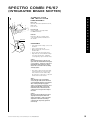
Spectro Combi P5/S7
(Integrated Brake Shifter) . .
Spectro System Components:
– Spectrolux V6 . . . . . . . . . .
– Spectro Front Hubs . . . . . .
– Spectro VT 3000/5000
(Front Drum Brake Hubs) .
– Spectro Brake Lever . . . . .
– Spectro Crank Sets . . . . . .
– Spectro Power Chain . . . .
.
.
.
.
.
.
.
.
.
.
.
.
.
.
.
.
.
.
.
.
.
.
.
.
.
.
.
.
.
.
.
.
.
.
.
.
.
.
.
.
.
.
.
.
.
.
.
.
.
.
.
.
.
.
.
18
24
34
40
46
. . . . . . . . . . . 53
. . . . . . . . . . . 54
. . . . . . . . . . . 56
.
.
.
.
.
.
.
.
.
.
.
.
.
.
.
.
.
.
.
.
.
.
.
.
.
.
.
.
.
.
.
.
.
.
.
.
.
.
.
.
.
.
.
.
58
61
62
63
APPENDIX
Spare Parts . . . . . . . . . . . . . . . . . . . . . . . . 66
Glossary . . . . . . . . . . . . . . . . . . . . . . . . . . 66
Technical information may be enhanced without prior notice. Released 10/98.
3
WHO WE ARE & WHAT WE MAKE
SRAM?
SRAM is the second largest bicycle
component supplier in the world.
Founded in 1988, SRAM’s World
Headquarters is located in Chicago,
Illinois USA. Currently, SRAM
has manufacturing facilities in
Ireland, Mexico, Taiwan, and with
the purchase of Sachs Bicycle
Component, also now has manufacturing in Germany, France, and
Portugal.
®
Twist shifters, designed to operate ESP and
traditional actuation ratio derailleurs.
®
™
Front and rear derailleurs designed to operate
with Grip Shift twist shifters and other
traditional actuation ratio shifters.
Rear derailleurs designed only to operate
with ESP compatible Grip Shift shifters.
™
SRAM
™
Cassettes and cranksets
for a majority of applications.
Internal gear hub systems
and leisure biking systems.
SRAM
BRAKINGSYSTEMS ™
™
Brakes & levers for a majority of
applications.
Hubs for a majority of applications.
™
Chains for all applications.
4
Technical information may be enhanced without prior notice. Released 10/98.
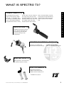
WHAT IS SPECTRO?
is a system of perfectly tuned and
attractively designed components
engineered for utmost comfort.
developed to respond with elegant
efficiency through an outstanding
gear range, delivering the highest
i n t r o d u c t i o n
SPECTRO
level of enjoyment, safety and
FREEDOM OF MOVEMENT
WHAT IS SPECTRO 3x7?
MAXIMUM FREEDOM
A comfortable touring system that
can go off road? 3x7 brings the best
of both worlds together with the
most userfriendly 21-speed
derailleur system on the market.
Featuring a single front chainring,
all 21 speeds are shifted at the rear
making every gear easily available
at all times. Whether climbing a hill
or shifting at a standstill, 3x7 is the
only 21-speed shifting system that
can accomplish both.
SPECTRO 3X7 REAR DERAILLEUR
New design with low friction
spring for easier shifting.
SPECTRO 3X7 GRIP
Completely redesigned ergonomic
grip cover and dual density
stationary for increased comfort.
SPECTRO 3X7 INTERNAL HUB
All 21 gears integrated in
the rear hub – easy to
shift and control in any
POWER GLIDE CASSETTE
Superior shifting, precision, and
durability.
Technical information may be enhanced without prior notice. Released 10/98.
situation, when pedaling
or at a standstill.
S P E C T R O
3X7
5
WHAT IS SPECTRO E12?
POWERFUL COMFORT
The premium power you receive
from the twelve closely spaced
gears of the E12 will make you a
believer in our ultimate riding
system. With performance ranges
like those of a 24-speed derailleur,
you can climb and drop gears
comfortably and easily with a single
twist of your wrist. At a standstill.
Under load on a hill. In mud and
rain. Never before has one gearhub
offered more smooth cruising
power when you want it. Where you
want it.
Every time.
SPECTRO E12 CLICKSTICK
Makes wheel removal a breeze.
quick and easy.
SPECTRO GRIP E12
12 speeds in the palm of your hand.
fast intuitive shifting. increased
comfort through ergonomic dual
diameter and dual density grips.
SPECTRO E12 INTERNAL HUB
The engineering masterpiece –
12 closely spaced gears with a
range of 339% – the right gear for
every terrain and speed.
S P E C T R O
E12
6
Technical information may be enhanced without prior notice. Released 10/98.
WHAT IS SPECTRO S7?
The S7 system is proof that
everything can be easier. The
increased performance and gear
range of these seven, finely spaced
gears offer unsurpassed reliability
and versatility for all rides of life.
Any environment is home, and
every challenge can be overcome.
Even necessary evils, like removing
and refitting the rear wheel, are
i n t r o d u c t i o n
SUPERIOR LEISURE
easier with the preset gear positions of the mini Clickbox. Free time
should be easy time. Even if the
rest of the world is being difficult.
SPECTRO S7 INTERNAL HUB
This improved version now offers a
303% gear range, the widest of all
7-speed hubs in the market. the
new spectro matte chrome finish
and design further increases the
value and appearance of this
reliable system.
SPECTRO GRIP AND
SPECTRO COMBI S7
Both shifters feature the new spectro
design with dual diameter, highly
comfortable and user friendly dual
density shifters.
MINI CLICKBOX
SPECTRO
S7
Technical information may be enhanced without prior notice. Released 10/98.
7
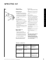
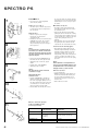
WHAT IS SPECTRO P5?
HARD WORKING
Like an old pair of blue jeans, only
a few things in life can speak to
true dependability. One of them is
the P5. Proven Reliability. Extra
comfort. Unprecedented 5-speed
performance with an enlarged gear
range of 251%. And a Mini Clickbox
with preset gears guaranteeing
quick wheel changes. Like that
friend that never complains, this is
the hard working system for daily
city riders. Nothing else compares.
SPECTRO P5 INTERNAL HUB
The new spectro design and finish
sets a new standard for reliable
city/commuter systems
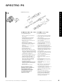
SPECTRO GRIP AND
SPECTRO COMBI P5
This ultra comfortable spectro design
dual density shifter makes for easy,
instant shifting action.
MINI
CLICKBOX
SPECTRO
P5
8
Technical information may be enhanced without prior notice. Released 10/98.
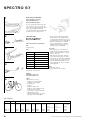
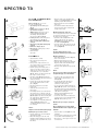
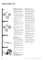
WHAT IS SPECTRO T3?
The heritage of the T3 system –
which has been proven a million
times over – is synonymous with
the durability and flexibility needed
for the urban dweller. Developed
and perfected for almost a century,
the 186% gear ratio, the strength of
the coaster brake, and the uncontested dependability of the T3 bring
legendary comfort, ease, and safety
to a complex world. The newly
designed Spectro Grip T3 Shifter
i n t r o d u c t i o n
CLASSIC SIMPLICITY
offers increased comfort, responds
quickly and precisely from mile one
to mile one thousand, making it the
perfect system for kids and adults
alike.
SPECTRO GRIP T3
Completely new design, matchingsuper-soft and comfortable grip
and stationary, great feel and
light action shifting for kids
and grownups.
SPECTRO T3 INTERNAL GEAR HUB
The classic. the reliable. the
improved one with spectro design
and finish. reduced shifting
forces and improved braking power.
SPECTRO CLICK T3
Great ergonomics and functionality
for smooth and precise shifting.
SPECTRO BANDIX *
Specifically designed for
children’s hands with smaller
diameter and low shifting forces.
SPECTRO
✴
Technical information may be enhanced without prior notice. Released 10/98.
Available for T3, P5, S7.
T3
9
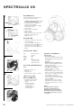
WHAT IS SPECTROLUX V6?
UNIVERSAL DYNAMO
The Spectrolux V6 is the ultimate
upgrade for many of our and other
hub systems. Optimized for silent
operation and elegant efficiency,
the Spectrolux dynamo is an easy
decision when contemplating additional simplicities in your life. Rain
or shine, this power generator is
designed to work perfectly –
without drag or slippage – in any
and all weather conditions.
SPECTROLUX V6
Whether on the P5, S7, SRAM
powerhubs or Shimano ® freehubs,
this revolutionary new dynamo sets
a new standard in the world of
power generators. Highly efficient,
easy to assemble, no drag when not
in use. State-of-the-art connectors
and safe integration at the rear hub
makes the Spectrolux V6 the
dynamo of choice.
Spectrolux V6
hub adapter
ring
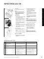
EVOLUTION OF SRAM INTERNAL
GEAR HUB SYSTEMS
(OLD/NEW NAMES)
SACHS 3x7
Spectro 3x7
SACHS ELAN
Spectro E12
SACHS SUPER 7
Spectro S7
SACHS PENTASPORT
Spectro P5
SACHS TORPEDO 3 speed
Spectro T3
10
Technical information may be enhanced without prior notice. Released 10/98.
t
r
o
p
p
u
Technical information may be enhanced without prior notice. Released 10/98.
s
SUPPORT
11
WORLDWIDE DISTRIBUTORS
UNITED STATES
Action Bicycle USA
217 Washington Avenue -A
Carlstadt, NJ, 07072
Ph: 800.284.2453
Quality Bicycle Products
6400 West 105th Street
Bloomington, MN, 55438
Ph: 800.346.0004
Brunswick Bicycles
2275 Half Day Road
Bannockburn, IL, 60015
Ph: 847.940.8777
Quantum Bicycle & Fitness
400 Venture Court, Suite 101
Verona, WI, 53593
Ph: 800.545.1229
Bicycle Tech International
3201 B Richards Lane
Sante Fe, NM, 87505
Ph: 800.558.8324
Quentin Distributors
845 Carol Court
Carol Steam, IL, 60188
Ph: 800.323.1741
Diamondback
4030 Via Pescador
Camarillo, CA, 93012
Ph: 800.776.7641
Raleigh Bicycle Co., USA
22710 72nd Avenue South
Kent, WA, 98032
Ph: 800.222.5527
Downeast Bicycle Specialists
Porter Road, P.O. Box 226
Fryeburg, ME, 04037
Ph: 800.242.1043
Riteway Products
2001 East Dyer
Santa Ana, CA, 92705
Ph: 800.869.9866
Euro-Asia Imports
3935 FootHill
La Crescenta, CA, 91214
Ph: 818.248.1814
Schwinn Cycling and Fitness
1690 38th Street
Boulder, CO, 80301
Ph: 800.245.1649
Giant Bicycle, Inc.
737 Artesia Boulevard
Rancho Dominguez, CA, 90220
Ph: 800.874.4268
Seattle Bike Supply
7620 South 192nd
Kent, WA, 98032
Ph: 800.283.2453
Great Northwest
2335 North West Savier
Portland, OR, 97210
Ph: 800.927.9242
Security Bicycle
32 Intersection Street
Hempstead, NY, 11551
Ph: 800.645.2990
Hans Johnsen Company
8901 Chancellor Row
Dallas, TX, 75247
Ph: 800.879.1515
Sinclair Imports
2755 Highway 40
The Hawley Company
One Hawley Drive
Lexington, SC, 29073
Ph: 800.822.1985
Island Cycle Supply
425 Washington Avenue North
Minneapolis, MN, 55401
Ph: 800.627.2453
J&B Importers, Inc.
P.O. Box 161859
Miami, FL, 33116
Ph: 800.666.5000
J&B Importers West, Inc.
P.O. Box 1248
Englewood, CO, 80150
Ph: 800.999.9228
J&B Importers Pacific, Inc.
P.O. Box 88808
Seattle, WA, 98138
Ph: 800.627.2453
KHS Inc., Distributor
1264 East Walnut Street
Carson, CA, 90746
Ph: 800.347.7854
The Merry Sales Company
1415 San Mateo Avenue
San Francisco, CA, 94080
Ph: 800.245.9959
Performance Cycle Products
22 South 6th Avenue
Mount Vernon, NY, 10550
Ph: 888.265.1876
Olympic Cycle Supply
5711 West Douglass Avenue
Milwaukee, WI, 53218
Ph: 800.236.8380
12
EUROPE
Verdi, NV, 89439
Ph: 800.654.8052
Trek Bicycle Corporation
801 West Madison
Waterloo, WI, 53594
Ph: 800.879.8735
United Bicycle Parts
691 Washington Street
Ashland, OR, 97520
Ph: 800.482.1984
Wilson Bicycle Sales
31157 Wiegman Road
Hayward, CA, 94544
Ph: 800.877.0077
World Wide Cycle Supply
100 D Executive Drive
Edgewood, NY, 11717
Ph: 800.330.2550
AUSTRIA
KTM Fahrrad GmbH
Harlochnerstrasse 13
5230 Mattighofen
Ph: +43 7742 409 132
Fx: +43 7742 409 126
BELGIUM
Transmission S.A.
Boulevard du Centenaire 4
1325 Dion-Valmont
Ph: +32 10 24 46 46
Fx: +32 10 24 47 77
CZECH REPUBLIC
vokolek import
rezlerova 308
10900 praha-petrovice
Ph: +420 2692 3399
Fx: +420 2692 3399
Zitny
Ceskobratske nam. 133/II
29301 Mlada Boleslav
Ph: +420 326 72 22 14
Fx: +420 326 72 22 14
DENMARK
Dan Agentur
Stationsvej 77
5792 Arslev
Ph: +45 65 99 24 11
Fx: +45 65 99 28 42
FINLAND
J. Syväranta Oy
Nervanderinkatu 5E 47/PL 64
F-00101 Helsinki
Ph: +358 9 490 137
Fx: +358 9 493 890
FRANCE
SRAM France
Rue de la Briqueterie
80210 Chepy
Ph: +33 3 22 26 01 00
Fx: +33 3 22 26 01 03
Eurostar, S.A.
Z.I. de la Seiglerie
44270 Machecoul
Ph: +33 2 40 78 24 00
Fx: +33 2 40 02 33 86
SUNN
Z.I. Ouest
31800 St. Gaudens
Ph: +33 561 94 85 71
Fx: +33 561 94 85 72
GERMANY
Hartje
Deichstr. 120-122
27318 Hoya
Ph: +49 4251 8110
Fx: +49 4251 811249
Epple
Mittereschweg 1
87700 Memmingen
Ph: +49 8331 7510
Fx: +49 8331 75197
Bico
E. Wiener Bike parts
GZR
Rabeneick/Schlote
Trisport
Veloring
ZEG
Technical information may be enhanced without prior notice. Released 10/98.
AUSTRALIA
GREECE
Groupe Sportif Pty. Ltd.
20 Harker Street
Burwood, Victoria 3125
Ph: +61.3.9888.9882
Proloco Trade d.o.o.
Partizanska 4
64000 Kranj
Ph: +386 64 38 02 00
Fx: +386 64 38 02 022
HUNGARY
Oerninn Hjol LTD.
P.O. Box 8036, Skeifan 11
Reykjavik
Ph: +354 1 88 98 92
Fx: +354 5 88 98 96
I TA LY
A.M.G. S.r.l.
Via Piave 10
23871 Lomagna (LC)
Ph: +39 039 5 30 11 67
Fx: +39 039 9 22 02 70
NETHERLANDS
Koch Kleeberg B.V.
Postbus 1069, Dukdalfweg 25
1300 BB Almere
Ph: +31 36 532 05 04
Fx: +31 36 532 25 48
Team Bike
SWEDEN
Vartex
Batterivägen 14
43232 Varberg
Ph: +46 340 850 80
Fx: +46 340 61 11 90
Bell Sports Canada
700 Chemin Bernard
Granby, PQ, J2G 9H7
Ph: +1.800.661.1662
Kempter Marketing
1271 St Louis
St Lazare, PQ, J7T 1Z9
Ph: +1.514.424.4600
SWITZERLAND
Intercycle
Industriegebiet, Haldemattstr. 3
6210 Sursee
Ph: +41 41 92 66 55 11
Fx: +41 41 92 66 352
ISRAEL
Vertex Cycle Systems
N O R W AY
U.K.
Stians Sport A.S.
Vollveien 13, Bygg D, POB 107
1324 Lysaker
Ph: +47 67 11 00 20
Fx: +47 67 11 00 42
Raleigh P&A
Triumph Road
NG 72 DD Nottingham
Ph: +44 115 9420202
Fx: +44 115 9282044
giant polska
ul. midgatowa 4
02-796warszawa
Ph: +48 22 645 1434
Fx: +48 22 645 1436
Fisher
Unit 2, Haslemore Business Centre
Lincolnway off
Lincoln Road
EN 1 1TE Enfield, Middx
Ph: +44 181 8053088
Fx: +44 181 8058821
harfa-harryson
ul. kozanowska 38/7
54152 wroclaw
Ph: +48 71 72 15 70
Fx: +48 7 13 27 80 92
Chickens & Sons
Bisley Works/Landpark Lane
LU6 2PP Kensworth, Beds
Ph: +44 1582 873583
Fx: +44 1582 873583
POLAND
CANADA
Norco Products Limited
1465 Kebet Way
Port Coquitlam, BC, V3C 6L3
Ph: +1.800.663.8916
Amsler & CO AG
Lindenstraße 16
8245 Feuerthalen
Ph: +41 5 26 59 36 36
Fx: +41 5 26 59 16 90
PORTUGAL
ciclo coimbroes
parca manuel da silva reis 122
4400 vila nova de gaia
Ph: +351 23 79 4461
Fx: +351 23 06 163
R E P. O F I R E L A N D
Raleigh Ireland Limited
Raleigh House,
Kylemore Road
Dublin 10
Ph: +353 1 626 1333
Fx: +353 1 626 1770
p
Casa Masfererrer
Pol. Ind. Congost-Avda.
San Julian, S/N Apdo Correos 89
E-08400 Granollers
Ph: +34 3 846 34 44
Fx: +34 3 846 53 55
p
ICELAND
S PA I N
u
Biker Kft.
Gyepsor u. 1
1211 Budapest
Ph: +36 1278 1021
Fx: +36 1278 1023
Velo-Vita Pty. Ltd.
Unit A, 602-612 Botany Road
NSW 2015 Alexandria
Ph: +61.2.9700.8177
o
SLOVENIA &
C R O AT I A
s
Gatsoulis Imports
8, Thesalonikis Street
14342 New filadelfia-athens
Ph: +30 1 25 12 779
Fx: +30 1 25 33 960
r
EUROPE (CONTINUED)
t
WORLDWIDE DISTRIBUTORS
Hobbys ltd.
3 dov. fridman street
52504 ramat gan
Ph: +972 5 2429 905
Fx: +972 3 7323 543
JAPAN
Kawashima Cycle Supply
No. 2-4-2 Kushiya-Cho Higashi
Sakai, Osaka 590
Ph: +81.0722.38.1557
Nichinao Shokai
6-16-8 Sotokanda Chiyodako
Tokyo 101
Ph: +81.0338.32.6251
NEW ZEALAND
Cycle Supplies
PO Box 33051
Christchurch
Ph: +64.3.338.6803
H.S. White & Sons
7C Anwen Place, East Tamacki
PO Box 58331 Greemouni
Auckland
Ph: +64.9273.7690
SOUTH AFRICA
Adventure Sports Trading
27 Elizabeth Lane, North End
6001 Port Elizabeth
Ph: +27.41.547101
Technical information may be enhanced without prior notice. Released 10/98.
13
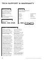
TECH SUPPORT & WARRANTY
WHO TO CALL
EUROPE
For fast SRAM dealer warranty
and technical support help,
please contact us at the
appropriate locations listed
hereafter.
(Other Countries: please contact
your local distributor.)
Dealer Helpdesk Number for the
following countries:
•
•
•
•
•
•
NORTH AMERICA
Austria
Belgium
Denmark
France
Germany
Italy
•
•
•
•
•
The Netherlands
Norway
Sweden
Switzerland
United Kingdom
Helpdesk Number:
(800)-346-2928
+ 8 0 0 / 77 2 6 4 3 5 7
S R
A M
H E
L P
SRAM 2 YEAR WARRANTY
In addition to standard legal
warranty entitlements, SRAM
components include a two year full
warranty beginning on the date of
purchase. This warranty is subject
to the following conditions:
3.
4.
1. IDuring the warranty period,
SRAM components with material
or production defects which as
a result adversely affect the
proper functioning of such components, shall either be repaired
or replaced with a functioning
SRAM component free of charge,
whereby we are free to determine whether repair or replacement should take place. If a
component cannot be replaced
or repaired, the purchaser shall
receive, free of charge, a
5.
component of higher value from
the current SRAM product line.
Defective components which
have been replaced become the
6.
sole property of SRAM.
2. Any other warranty claims not
included in this statement are
void. This especially includes
any disassembly or assembly
14
costs (for instance by the
dealer), which shall not be
covered by SRAM.
Warranty claims are only valid
upon presentation of a proper
proof of purchase.
Parts subject to normal wear and
tear (for example brake sleeves,
brake pads, chains etc.) and
damage which is caused by
improper use, specifically
caused by disregard for our
assembly and operating instructions, shall not be covered by
this warranty. Furthermore, this
warranty shall not cover
damages caused by the use of
parts of different manufacturers
or otherwise which are not
compatible or suitable for use
with SRAM components.
The servicing of a valid warranty
claim shall neither extend this
warranty nor establish a
warranty period.
If a defect is discovered, please
contact the dealer where the
bicycle or the SRAM component
in question was purchased.
Technical information may be enhanced without prior notice. Released 10/98.
g u i d e l i n e s
&
t i p s
TIPS & GUIDELINES
Technical information may be enhanced without prior notice. Released 10/98.
15
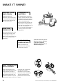
MAKE IT SHINE!
KEEPING YOUR
BIKE CLEAN
CLEANING OF
SHIFTERS
Keeping your bike and
components clean and correctly
lubricated willkeep performance
highand usually slow down the
wear and tear on parts.
We recommend that the internal
cleaning and lubrication of shifters
should only be done when shifting
performance has deteriorated due
to excessive contamination.
We have found that, generally, the
deterioration of shifting efficiency
starts with the contamination of the
cable and housing system.
This causes high friction buildup in
a shifting system and should be
examined first.
HOW THE
PROS DO IT
Wanna know how the pros do it?
Use mild soap and water and a
large sponge or soft brush to
gently work off the mud and crud.
Then rinse with a clean water
sponge bath.
THINK OF RELUBRICATING
After the cleaning of any
component, always properly
re-lubricate if required.
Caution: Be careful how you use
degreasers, citrus or otherwise,
on your bike components.
Degreasers can bloat, soften, or
otherwise damage parts.
KEEP THE BIKE ON
BOTH WHEELS
Always keep the bike on both
wheels when cleaning with water.
Hanging the bike vertically or
upside down to hose it clean can
lead to waterdrainage into now
vulnerable components. Pay and
spray? Avoid it. Quick rinses at the
16
car washor even spraying with
a garden hose can drive
contaminants past the sealed
mechanisms of your components.
Thiscould compromise their
performance and shorten their
lifespan.
Technical information may be enhanced without prior notice. Released 10/98.
i n s t r u c t i o n s
INSTRUCTIONS
Technical information may be enhanced without prior notice. Released 10/98.
17
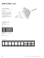
SPECTRO 3x7
SPECIFICATIONS
3-speed-hub with 7 speed sprocket cassette
Type MH C3721F
Spectro 3x7 combines the best of the two
gear shifting principles – chain (derailleur)
and hub gears – in an intelligent system.
Because all 21 speeds are changed on the
back wheel the installation of a chain guard
on the chain wheel is possible.
Gear shifting is performed by means of the
ergonomically-designed rotational shifter –
Spectro Grip 3x7.
TECHNICAL DATA
3 speed hub (with alu sleeve)
Total ratio: 434 %
(hub with derailleur gear T=12/28)
Ratio:
Total ratio of hub: 186 %
Gear
Ratio
1
1 : 0.73
2
1:1
3
1 : 1.36
Sprocket cassette:
POWER GLIDE 7 speeds, 12/14/16/18/21/24/28
teeth
Crankset:
Spectro single speed, 33 teeth
Spoke length table
Cross
3x
18
Tire Size
47–406
37–490
47–507
37–540
47–559
37–590
47–622
32–622
28–630
20" x 1.75 x 2
22" x 1 3/8
24" x 1.75 x 2
24" x 1 3/8
26" x 1.75 x 2
26" x 1 3/8
28" x 1.75
28" x 1 5/8 x 1 1/4
27" x 1 1/4 fifty
37–622
28–622
185/182 mm
226/224 mm
234/232 mm
251/249 mm
261/259 mm
275/273 mm
32–630
28" x 1 5/8 x 1 3/8 28" x 1 1/8 x 1 3/8
27" x 1 1/4
291/289 mm
295/293 mm
291/289 mm
Technical information may be enhanced without prior notice. Released 10/98.
SPECTRO 3x7
i n s t r u c t i o n s
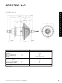
A S S E M B LY D ATA
173
19
135 ± 1.5
32.5
55
47.5
67.5
45
35
20
F2
F1
6.5
Chainline
Ø 2.6
+ 0 . 15
TK
T
A 2 max
1/2 GW
A 1 max
3x7 MH
Over locknut dimensions
Axle ends 2 flat
Axle thread
Max. dropout width dimensions
Max. dropout width dimensions
Sprockets
Chainline at sprocket cassette
– Number
– Diameter
– Ref. circle diameter
Spoke flange distance to 1/2 GW
Spoke flange distance to 1/2 GW
GW
CL
135
8.6
FG 10.5
9.5
9.5
7-speed cassette T = 12/28
45
Ds
TK
F1
F2
36
2.6 + 0.15
67
20
35
T
A1
A2
± 1.5
max
max
Spoke hole
Axle nut torque
30 – 40 Nm
Dimensions in mm
Technical information may be enhanced without prior notice. Released 10/98.
19
SPECTRO 3x7
A S S E M B LY
REQURIREMENTS
1
Chain guard/chain guide fork
• Chain guard Supplier: (see Fig. 6a)
de woerd bv
Stationsweg 167
Postbus 23
3770 BARNEVELD
The Nederlands
Fon (+31) (0) 3 42-41 21 41
Fax (+31) (0) 3 42-41 21 41
Advice:
Use in tandem not permitted.
1a
Derailleur gears
The following preconditions apply to
the rear dropout for
max: 9.5
min: 5.5
SW 8
bracket
a) Assembly with bracket
• The angle (a) between the axle carrier
and the centerline of the lower rear wheel
fork must be between min. 20° and max.
30° (Fig. 1).
• If the dimension “max. 9.5” between the
smallest sprocket and the outside of the
dropout is exceeded a gear unit with an
inward offset cranked bracket of type no.
1120 441 020 must be used (Fig. 1a).
• The chain guide fork (optional; see
11, Fig. 6a) – chainwheel. It is bolted inside
the chain guard.
6
X2
6a
Outside-Ø dA max. 220 mm
Handlebars
• Rotational shifter
Spectro Grip 3x7
Handlebar diameter 22.0 – 22.4 mm
Length of straight cylindrical end of
handlebars min. 150 mm + width of brake
lever clamp
Chain guard
7
b) Direct mounting (Fig. 2)
• The dropout must be between 4 mm and
max. 8 mm thick. Dropouts which are
downward opening are permitted.
2
4 5 6 6a
1
β
A
B
25˚– 30˚
26…30 mm
6…10 mm
c) Mounting both with bracket and direct
• The geometry of the seat tube strut and the
rear wheel fork in connection with the
choice of the smallest sprocket must
correspond with the dimensions shown
here (see Fig. 4).
4
X1
80
90
105
cable housing
280
300
330
3
7
9
Frame – soldered outer stops for
cable housings
• The most advantageous combinations of
outer stop positions and the required cable
housing length can be seen on the
following figures and tables.
a) Fitting to the lower rear wheel fork with
bracket mounting (Fig. 5)
9…13 mm
2
8
Direct mounting (Fig. 3)
• The distance between the smallest
sprocket and the bearing surface of the
gear unit on the dropout must be 9–13 mm.
3
11
Chain guide fork
dA
8
10
b) Fitting to the lower rear wheel fork with
direct mounting (Fig. 6).
12 T
13 TT
12
14 T
14
15 TT
16 T
5
X
X
X
X
X
X
X
> 35 mm
37 mm
>> 35
mm
> 39 mm
> 41
39mm
mm
>
> 43 mm
X2
90
100
115
cable housing
280
300
330
3
1a
• The inside diameter of the outer stop to
carry the cable housing must be 6.05 mm.
1
11
X1
20
Technical information may be enhanced without prior notice. Released 10/98.
2
8
SPECTRO 3x7
13
11
10
14
Clamping
bolt
Adjuster
barrel
Hub/Derailleur
• Spoke hub as normal
(see Spoke length table)
• Place spoke protector disc (1) on shoulder
of hub, mount dust cover (2), push sprocket
cassette (3) onto driver, fit spacing washer
(4) and the smallest sprocket (5) with its
shoulder foremost. Screw in ring (6) and
tighten up, screw small pull rod (7) into the
hub axle (Fig. 7).
If provided push cone disc (6a) onto the
axle end on the sprocket side.
• Screw derailleur onto the frame dropout.
(Short cage Fig. 8)
Direct mounting:
– 5 mm allen key
– Tightening torque 8–10 Nm
With bracket:
– 8 mm wrench
– Tightening torque 4–5 Nm
• Fit wheel in dropouts and align.
• Place tabbed retaining washers (8) on both
sides of the axle – the serrations must
bear against the dropout – and the prongs
must engage in the dropout slot (Fig. 9).
• Tighten up axle and chain guide nuts.
15 mm wrench, tightening torque
30–40 Nm.
Advice:
When tightening up the chain guide nut
(Fig. 13) pull taut the small pull rod 11 so
that it isn’t damaged.
Rotational shifter
• Slide shifter (1) onto handlebar.
• Slide on the two grip washers (1a).
• Fit fixed grip (2) on the ends.
• Position shifter (1) against the fixed
grip (2).
• Align shifter (1) on handlebars and tighten
up with clamping bolt (3). 3 mm allen key,
tightening torque 1.5 Nm (Fig. 10).
14a
a) Hub: Set left-hand shifter on handlebars
to gear position “3”. Feed control cable
into juster sleeve (10, Fig. 13), fix it at the
appropriate length with the clamping bolt
and push it onto the small pull rod (11) until
the cable is taut. Cut off any excess cable
length. 2.5 mm allen key, tightening torque:
1.5 Nm.
i n s t r u c t i o n s
A S S E M B LY
12
b) Derailleur: Set right-hand shifter on
handlebars to gear position “7”. Feed
shifter cable through outer stop on the
lower rear wheel fork and push on cable
housing. Then route shifter cable through
adjuster barrel and the clamping bolt to the
derailleur unit. Pull shifter cable taut and
tighten clamping bolt. Make sure that the
cable housing is correctly seated in the
adjuster barrel and outer stop (Fig. 14).
Determination of chain length (see Fig. 14a)
• Place chain over front chain wheel and
the largest rear sprocket and add two
chain links.
• Close chain
SHIFTING
ADJUSTMENT
Hub
• To adjust, the cable must be tightened up
in 3rd gear so as to transmit the shifting
movement directly to the hub. Check
whether the ends of the cable housings
are correctly located in the outer stops.
Adjustment:
• Put shifter into gear position “3”, rotate
pedals to make sure that the gear is
actually engaged.
• Push adjuster sleeve (10) far enough onto
the small pull rod (11) until the cable is taut
(Fig. 15) but without pulling the small pull
rod (11) out of the chain guide nut (12).
Chain
15
11
10
16
H
Advice:
Do not use greasy materials when fitting the
left and right-hand fixed grips (2) onto the
handlebars
• Feed the control cables through the cable
housings and the double outer stops. In
doing this ensure that the cable housings
are located properly into the bottom of the
adjuster barrels and the outer stops and
that these are tightly screwed to the down
tube (Fig. 11). Fit the double pulley clip
directly above the bottom bracket on the
seat tube and feed the shifter cable over
the pulleys to the rear (Fig. 11).
• If a cable guide is fitted beneath the
bottom bracket, press the shifter cables in
the pregreased pulley guides and route
them to the rear – please do not use open
designs, otherwise the shifter cable could
slip out when loose. For assembly a hole is
bored in the bottom bracket housing and
the cable guide is screwed tight (Fig. 12).
• Connect control cable with hub and
derailleur
Technical information may be enhanced without prior notice. Released 10/98.
Checking:
• Set shifter to gear position “1”. Rotate
pedals to make sure that 1st gear is
actually engaged.
• Check whether the small pull rod can be
pulled even further out of the chain guide
nut.
• If yes, retension the cable pull, see 1st
adjustment.
• Check again.
Advice:
If the adjustment is incorrect a short jerk
can occur when starting or there may be a
slight creaking noise which may be heard in
the drive system (this does not mean that a
defect exists).
Derailleur
Presetting the derailleur
(best done without the chain)
• Move upper chain guide pulley to beneath
the smallest sprocket (and hold it there),
then turn the limit screw H in or out until
21
SPECTRO 3x7
the guide pulley lines up with the center of
the smallest sprocket (see Fig. 16).
• Move upper chain guide pulley to beneath
the largest sprocket (and hold it there),
then turn the limit screw L in or out until
the guide pulley lines up with the center of
the largest sprocket (see Fig. 17).
• Slowly move the derailleur gear by hand
back to below the smallest sprocket.
• The derailleur is fitted with an adjusting
screw which permits the gap between the
chain guide pulley and the sprockets to be
adjusted. When adjusting with the chain
fitted and the upper chain guide pulley
below the largest sprocket, set the gap in
such a way that when pedalling backwards
the pulley just runs clear of the sprocket.
17
18
Fine tuning of the derailleur:
• Set right-hand shifter to gear position “7”.
This position corresponds with the chain
on the smallest sprocket.
• Rotate pedals. If the chain already touches
the 2nd sprocket or if it shifts onto it,
screw adjuster barrel 1 (see Fig. 20)
clockwise until the contact noise stops and
the chain shifts back onto the smallest
sprocket.
• Set rotational shifter to gear “6”,
sthereby rotate pedals.
• If the chain does not shift, turn adjuster
barrel (1) in an anti-clockwise direction
(see Fig. 20), in other words increase the
cable tension until the chain shifts
correctly onto the 2nd sprocket.
19
Checking the gear shifting system:
• Rotate pedals forwards and check by shifting through each of the gears in turn in
both directions adjusting as necessary.
A
Advice:
If in the course of time further adjustments
become necessary the adjuster barrel A
(Fig. 19) on the right-hand rotational shifter
can also be used.
20
DISMANTLING AND
A S S E M B LY O F T H E H U B
Dismantling and reassembly of the hub: See
the assembly instructions for the freewheeling hub Spectro T3. The exploded
drawing (Fig. 22) shows the exact installation
position and direction of the individual parts.
MAINTENANCE/
SERVICING
Spectro Grip 3 x7, cabel replacement
• Remove cap (1, Fig. 21) from assembly window (2). Turn rotational shifter forwards to
its stop until the cable head (3) is visible in
the assembly window. Push head out of the
cable guide and remove control cable. Insert new control cable, fit on frame accordingly and pull as far as stop in the cable
guide on the shifter.
Connect control cable with adjuster sleeve
or derailleur and close assembly window.
Adjustment (see page 21/22).
Advice:
When replacing a shifter cable, always
replace the cable housing with new,
compressionless housing.
Derailleur
• Lubricate slider under bottom bracket
(control cable guide).
• Clean chain as necessary and oil lightly.
• Chain links must always be flexible.
Hub
• The 3 speed hub is sufficiently lubricated.
• Oil control cable and small pull rod
occasionally.
• Do not apply water under pressure to hub
gears when cleaning (e.g. strong water jet,
high-pressure cleaner etc.) – if water
does penetrate the unit it could lead to
functional problems.
• If the side play on the rear wheel is too
great arrange for a specialist to adjust
the bearings.
• If the bicycle is not used for long periods
set the rotational shifter to gear position “3
or 7” to relieve the pressure on the system.
Fig. 22:
Exploded
drawing
hub
1
21
3
1
2
22
Technical information may be enhanced without prior notice. Released 10/98.
SPECTRO 3x7
Likely Cause
Corrective Action
Short jerk upon start-up
or slight clicking noise
(indicator chain moves w/o
any gears shifting.
• Incorrect gear adjustment.
• Readjust gears.
Difficulty in shifting
• Incorrect gear adjustment.
• Readjust gears.
Problem
i n s t r u c t i o n s
TROUBLE SHOOTING GUIDE
Hub:
• Check gear cable routing, lubricate
shifter cable if necessary.
• Clean or replace cable and housing
if necessary
• Bearings adjusted too tightly
• Have bearings adjusted by a specialist.
• Loose locknuts.
• Same as above.
Chain shifts beyond smallest rear sprocket
against the frame stays.
• Limit screw H is not
screwed in far enough.
• Screw in limit screw until the upper pulley
is aligned with the smallest sprocket.
Chain shifts poorly or not at all onto the
smallest sprocket.
• Limit screw H is screwed in too far.
• Screw out bolt until upper pulley is aligned
with the smallest sprocket.
• Shifter cable is too tight.
• Screw in the limit screw clockwise (or at
the right hand shifter) until chain shifts
down with ease.
• Shifter cable does not slide correctly.
• Check shifter cable and lubricate if needed.
• Clean or replace cable and housing.
• Shifter cable housing is too short.
• Mount a longer control cable.
• Limit screw L is not
screwed in far enough.
• Screw in limit screw until upper pulley is
aligned with the largest sprocket.
• Rear derailleur or deraillleur
hanger are bent.
• Realign or replace.
Chain shifts poorly to larger sprocket, but
easily to smaller sprocket.
• Shifter cable is not taut enough.
• Turn adjusting barrel counter-clockwise
(or at right hand shifter) until the chain
shifts easily to smaller sprocket.
Chain shifts easily to larger sprocket, but
poorly to smaller sprocket.
• Shifter cable is too taut.
• Turn adjusting barrel clockwise (or at right
hand shifter) until the chain performs
downshifts easily.
• Shifter cabe does not slide correctly.
• Check shifter cable and lubricate if needed.
• Clean or replace cable and housing.
• Shifter cable housing is too short.
• Mount a longer control cable.
Chain hangs loose when freewheeling.
Derailleur drivetrain:
Chain shifts beyond largest rear sprocket
and drops against the spokes, or
the cage plate runs into the spokes.
Technical information may be enhanced without prior notice. Released 10/98.
23
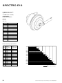
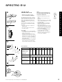
SPECTRO E12
Type MH 12110 with coaster brake
Type MH 12010 without brake
TECHNICAL DATA/
A S S E M B LY
REQUIREMENTS
Total ratio:
Hub: 339%
Single ratio:
Gear
Gear ratio
1
1 : 0.697 = 1.433
2
1 : 0.851 = 1.174
3
1:1
4
1 : 1.179 = 0.848
=1
5
1 : 1.333 = 0.750
6
1 : 1.481 = 0.675
7
1 : 1.612 = 0.620
8
1 : 1.766 = 0.566
9
1 : 1.915 = 0.522
10
1 : 2.061 = 0.485
11
1 : 2.217 = 0.451
12
1 : 2.364 = 0.423
Distance travelled by one pedal revolution
Gear
Citybike 26"
47–559
(26 x 1.75)
Trekkingbike 28"
37–622
(28 x 13/8 x 15/8)
1
2.09 m
2.23 m
2.23mm
2,23
1st
1. gear
Gang
2nd
gear
2. Gang
2,72 mm
2.72
3,19
3.19mm
3rd
gear
3. Gang
2
2.55 m
2.72 m
3
3.00 m
3.19 m
4th
gear
4. Gang
4
3.53 m
3.77 m
5th
gear
5. Gang
5
4.00 m
4.26 m
6th
gear
6. Gang
6
4.44 m
4.73 m
7th
gear
7. Gang
7
4.83 m
5.15 m
8. Gang
8th
gear
8
5.29 m
5.64 m
9th
gear
9. Gang
9
5.74 m
6.12 m
10
6.18 m
6.59 m
11
6.64 m
7.08 m
12
7.08 m
7.55 m
3.77
3,77 mm
4,26
4.26mm
4.73mm
4,73
5,15
5.15 mm
5.64
5,64 mm
6,12
6.12 mm
6,59
6.59 mm
10. Gang
10th
gear
7,08
7.08mm
11th
gear
11. Gang
7.55
m
7,55 m
12th
gear
12. Gang
0m
1m
2m
3m
4m
5m
6m
7m
8m
Rear-wheel revolution
24
Technical information may be enhanced without prior notice. Released 10/98.
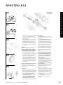
SPECTRO E12
~ 230 mm
Ø 18 … 22 mm
Clip
Clickstick
2
3
3
2a
1
4
4
Axle bolts
Brake arm clamp
with bolt and nut
M 5 resp. M 6
5
Chain guard:
available from De Woerd, Netherlands
(documents, e.g. installation requirements
and assembly instructions, on request).
i n s t r u c t i o n s
Chain/Chain ratio:
• Use exclusively 1/2" x 3/32" roller chain.
• For optimal performance, use a chainring
with 38 teeth or more/sprocket with 26
teeth only.
Wheel size:
only 26"/28" wheels are suitable for use.
2
SYSTEM COMPONENTS/
ACCESSORIES
Bicycle Frame:
• The hub is not suitable for tandem use.
For other special applications, please
contact your nearest dealer or Sachs
representative.
• Minimum thickness of dropouts: 4 mm
• Maximum total thickness of axle assembly
(i.e. dropout + mudguard stay, etc…): 9 mm
• Additional parts on axle between dropout
and hub are not allowed.
• The frame geometry in the dropouts area
should have enough room (see shaded
area) to allow for the installation of hub
and its movement into dropouts
(see Fig. 1).
Suggestion: make a trial installation first!
• It should be possible to remove and
replace wheel with inflated tire
(Make a trial assembly first!).
• Chainstay Ø 18…22 mm in the clip attachment area of Clickstick (see Fig. 2).
• For brake hubs, the frame chainstay must
be strong enough to withstand a wheel
torque of 250 Nm (2213 in.lbs.).
• Do not use frames with vertical or open
rear dropouts
1
2
3
4
12-speed hub (Illustration w/coaster
brake, see Fig.4 and 5)
Rotational shifter (delivered in gear
position “12” – Warning – do not operate
before assembly, cable can get clamped
and break as a result).
a) Shifting cable with continuous cable
housing.
(Cable housing delivered in following
lengths: (L) 1200/1300/1400/1500 mm.)
b) Adjustment barrel
c) Cable clamp assembly
d) Fastening bolt
(see Fig. 6)
Shifter cable – Frame attachment, 3x on
down tube – see 3, Fig. 3 – if desired 1x at
chainstay, i.e. direct mount frame Clamp,
(Fig. 7) or with bracket (Fig. 8), or brazed
on parts (Cable housing must be movable
in attachment element).
Roller chain: Use 1/2" x 3/32".
Handlebars for rotational shifters:
• Handlebar diameter 22.0…22.4 mm
• Minimum length of straight area on
handlebar: 150 mm + width of brake
lever clamp.
Axle bolts
Sprocket:
26 teeth
Clip
Seatstay
Drive side
D
Clickstick w/cable
clamp assembly
6
L
➤
2d
Direct mount
frame clamp
Chainstay
Drive side
B
NEW
NEW
A
OLD 135 mm
8
m
min 30 mm
min 45 mm
9 mm
➤
7
6m
2b 2a
6 mm
2c
min 30 mm
D
NEW
Frame clamp
w/bracket
C
Technical information may be enhanced without prior notice. Released 10/98.
Measuring basis Pt. A
Fig. 1
25
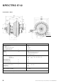
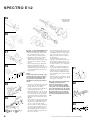
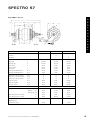
SPECTRO E12
A S S E M B LY D ATA
141.6
135
58.6
c l = 40.2
68
Ø
Ø
Ø
Ø
47.3
3.3
143
132
115
105
9.3 X 1
6.8
X2
A
Ø 74
Ø 69.6
A
7.3 H13 (+0.22)
Ø 3.0
10 –
+ 0.15
(2
0.2
Ø 2.6
+ 0.15
x)
F2
M16x1 (2x)
90
F1
Spectro E12 with coaster brake MH 12110
Over locknut dimension
Axle length
Axle ends (projection left & right)
Axle end double (left & right)
Frame droupouts, thickness
Chain line
Chain ratio
A
“cl”
Roller chain
Spoke hole
– Number
– Diameter
– Circle diameter
Center of hub to center
of flange-drive side)
Center of hub to center
of flange-non-drive side
Counter nut to dust cap distance
Counter nut to dust cap distance
Ø Left dust cap
Ø Right dust cap
Torque on axle bolt
Torque on brake lever clamp M5
135
141.6
3.3 each
10 – 0.2
min. 4, max. 9
40.2
only chainring with 38 teeth or more
only hub sprocket with 26 teeth
exclusively 1/2" x 3/32"
36
3.0 + 0 . 15
105
F1
20.7
F2
37.9
X1
X2
9.3
6.8
74
69.6
/ 2.6 + 0 .15 (max. spoke diameter: 2.0)
/ 132
(brake lever side)
(drive side)
30…40 Nm
2 … 3 Nm
Accessories: Clickstick, dust cap, sprocket, circlip, brake arm clamp, 2 axle bolts
Dimensions in mm
26
Technical information may be enhanced without prior notice. Released 10/98.
SPECTRO E12
LACING AND
INSTALLING HUB
Advice:
a tool can be used to hold the hub in the
vice. This tool threads into the hub’s axle.
Tool part No. 00 2324 002 000.
• Maximum spoke diameter: 2.0 mm
• Please note: Alignment spoke/Nipple
The high flanged hub results in a relatively
tangential running spoke for three crossed
spokes. Some rims do not allow for the flat
angle of spoke nipple. This results in an
undesirable kink between nipple and spoke
(see Fig. 9).
In order to make sure that the spoke and
nipple align, we recommend the following
alternatives:
• Choose the appropriate combination of
nipple and rim
• Cross spokes twice instead of 3 times
• Use embossed rims
incorrect
correct
10
Rim
Rims Ø “A”
Spoke length:
• For examples, refer to spoke length table.
• For hub dimension used to determine spoke
length, refer to page 26.
• On request, we can determine the most
appropriate spoke length for your specific
application needs. For this, we would need
the dimension for rim Ø “A” (see Fig. 10 –
measurement on the basis of two opposing
spoke nipple heads).
• Calculated spoke lengths are approximate
values. They must be checked through
lacing attempts and adjusted accordingly.
Spoke nipple
11
2
• Place dust cap (1) and sprocket (2) on
driver.
• Press sprocket circlip (3) into groove.
(Fig. 11)
• Open Clickstick (4). To do so, press ribbed
surface of tabs (5) lightly and loosen cap
from element (5a).
• Pull cable (6) slightly out of Clickstick
(Fig. 12). Shifting adjustment should be
done in gear position 12.
• Route cable head through small opening
and push through under webs (7) and (7a)
in the direction of cabel head hanger (8).
• Place head in hanger (8).
• Pull cable (6) and hold tightly. Pull red
locating wedge (9) from toothing.
• Slowly release cable so the spring can
wind up the cable and change the gear
from 1 through 12. (Fig. 13).
i n s t r u c t i o n s
9
Mounting
Tool
1
3
Spoke length table:
2
Wheel size
3
1
26"
26"
28"
28"
28"
28"
28"
28"
545
547
596
606
609
610
611
612
Crossed 2 X
• right (Large flange)
• left (Small flange)
227.1
237.5
228.0
238.5
252.0
262.5
257.0
267.4
258.4
268.9
258.9
269.4
259.4
269.9
259.9
270.4
Crossed 3 X
• right (Large flange)
• left (Small flange)
247.2
353.1
248.2
254.0
272.0
277.9
276.9
282.8
278.3
284.3
278.8
284.8
279.3
285.3
279.8
285.8
Diameter “A” of rim
(Fig. 10) measurement
on the basis of two
opposing spoke
nipple heads
5a
12
Spoke length when:
5a
6
4
5
Dimensions in mm
13
7a
8
9
7
6
Technical information may be enhanced without prior notice. Released 10/98.
27
SPECTRO E12
• Bring Clickstick (4) to hub and position the
crown (4a) so that red arrow on the hub is
visible in the middle of window (4b). By
applying a little pressure, snap crown
onto hub (Fig. 14).
14
Mounting rear wheel into frame
• Place chain (11) on sprocket (2); fit wheel
in rear frame; route ends of axle in the
grooves of dropouts; adjust wheel in frame,
mount axle bolts (10) with washers
ribbings point towards the dropouts, and
tighten. Use a 15 mm wrench and a torque
of 30–40 Nm (266–354 in.lbs). (Fig. 15)
4b
4a
4
Caution:
Use original bolts only.
Mounting brake arm clamp
• ELAN-Clamp (round, Ø 14, 15, 16 mm)
Tighten brake lever clamp (13) so that the
centering shoulder (x) fits into the bore on
the brake lever (Fig. 16a). Screw and nut
M5, self-locking.
Wrench 8 mm, screwdriver, Torque 2–3 Nm
(18–27 in.lbs.).
15
10
2
11
Caution:
Clamp must sit on frame with
absolutely no play!!
4
• Standard clamp
Mount brake lever to the outside of clamp
extension. (Do not mount inside of
extension, Fig. 16b).
Screw and nut M6, self-locking.wrench 10
mm, screwdriver, Torque 2–3 Nm
(18–27 in.lbs.).
Caution:
Clamp must sit on frame with
absolutely no play!
16 a
ROTATIONAL SHIFTER
AND CABLE
•
•
•
•
Slide shifter (1) onto handlebar
Add 2 thrust washers (3)
Mount fixed grip (2) onto end of handlebar
Without applying pressure, slide shifter
(1) against fixed grip (2)
• Adjust shifter (1) on handlebar and
tighten with bolt (4) with a torque of
1.5 Nm (13 in.lbs.). (Fig. 17)
13
Caution:
Fixed grips on the right and left of handlebar
must fit snuggly, therefore do not use any
lubricants or solvents to install them.
Fixed grips (left and right) provide an axial
safety function. For this reason, they should
be mounted in such a way as to make sure
they do not slip off handlebar.
screw
M5
x
28
nut M 5,
selflocking
Caution:
Do not operate shifter before installing and
hooking cable to spring shell.
• Place shifter cable along frame as
described.
• Put shifter in gear position 12
• Guide cable clamp assembly (5) onto
extension bolt of spring shell (6) and
snap it in by turning it over (Fig. 18)
• Insert adjusting barrel (7) with square nut
in the recess (8) inside Clickstick.
• To close cap, slide locking parts (9) in the
openings of Clickstick housing and snap in.
• Fasten Clickstick onto chainstay with
clamp (12) (Fig. 19)
• Check length of shifter cable (maintain
relatively narrow cable housing arc (2a)).
• Attachment takes place three times on
down tube, (Fig. 20). Means of attachment:
brazing parts, frame clamps with brackets
or direct mount. Avoid clamping of the
cable housing and narrow bends.
Cable housing must be movable inside
attachment.
16b
Pipe clamp from standard
range (round or oval,
various dimensions), M6
bolt + nut (self-locking)
brake-arm
Pipe clamp form
standard range (round,
Ø 12.5/14/16 mm) M6
bolt + nut (self-locking)
SHIFTING
ADJUSTMENT/
FINAL CHECK
• To check, shift through all gears
(gear 12–gear 1) with rotational shifter.
Shifting adjustment must take place in
gear position 6.
• To properly control the cable tension
during shifting adjustment, it is necessary
to shift to the 1st gear then shift to the 6th
which is the shifting adjustment position.
• Rotate adjusting barrel (7) until the red
arrows (10) in window (11) line up (Fig. 21).
• Rotate shifter to gear position 7 and back
to 6. If adjustment marks no longer line up,
check that the cable moves freely and
repeat adjustment procedure.
• Spin crank and shift through all gears.
• For the coaster brake hub, check proper
function of brake.
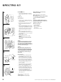
DISASSEMBING AND
ASSEMBLING HUB
Disassembly (see detailed drawing on
next page)
• Remove snap ring (2), sprocket (3) and dust
cover (4).
• Thread tool into axle and clamp in vice
(sprocket side).
• Loosen nut (25, 22 mm across flats) while
holding flanged nut (24, 32 mm across flats)
in position – remove both nuts.
• Disassemble brake arm (23) and remove
bearing retainer (22).
• Lift off hub shell (21), remove bearing
retainer (20) and brake cylinder (19).
• Remove cir-clip (18)
Caution:
Thrust washer (17), toothed lock washer (16)
and locking disc (15) are under spring
pressure – take off parts and re-move spring
(14).
17
1
3
2
4
18
5
6
7
8
19
12
9
Technical information may be enhanced without prior notice. Released 10/98.
SPECTRO E12
25
1
19
17
2a
3x
16
18
Exploded drawing
Type MH 12110 with
coaster brake
22
21
15
14
13
20
12
8
11
c b
4
10
a
7
6
9
21
23
24
i n s t r u c t i o n s
20
3
5
2
10
1
11
• Pull gear assembly (7) upwards – it will be
necessary to exert some force since the
friction spring on the axle locks and must
be pushed upwards.
• Remove individual parts – friction spring
(13), lining (12), brake cam (11), cylindrical
rollers (10, 8 rollers), roller guide ring
assembly (9) complete with springs, safety
devices and pawls (8a,b,c) from the gear
block and remove bearing retainer (6) from
the Clickbox.
7
22
r
s
q
p
j
Caution:
When removing the roller guide ring (9),
make sure the pawls (8b) have springs attached. If one or more springs are missing,
make sure that they are not in the gear box –
this could result in future malfunctions.
i
• In the freewheel version, a coupling sleeve
(j, Fig. 22) is fitted instead of parts 10 to 16
in picture above. In addition, the roller
guide ring of the freewheel version (i) is a
different shape (Fig. 22). In place of brake
arm (No. 23), lock washer (p), adjusting
cone (q), dust cover (r) and a washer with
two lugs on the inside diameter (s) are fitted. See Fig. 22.
23
Working on individual parts/lubricating parts
Once the hub components have been
dismantled, it is also important to take note
of the following:
24
8b
8a
9
Cleaning parts:
• Only brake components, brake cylinder,
brake ams, cylindrical rollers, toothed lock
washer, locking disc and roller guide ring
with stop notches should be degreased in
the cleaning bath. Do not under any
circumstances clean the friction springs
with solvent or degreaser.
• Only clean axle assembly with shifting
component and gear assembly on the
outside using a paintbrush to prevent
degreasing inaccessible lubricating points.
Technical information may be enhanced without prior notice. Released 10/98.
Lubricating parts:
• On the gears, wet the inside sun wheel
catches and outside ring gear catches with
a drop of oil.
• On the axle with shifting component, oil
the shifting cam rods in the axle profile
and around the “prongs” of the shifting
sleeve on both sides. Fill each of the four
recesses around the circumference of the
shifting sleeve with one drop of oil. Using
the shift cable, turn the cable pulley
several times and make sure it does not
jam – all shifting rods in the axle profiles
must move at least once. Do not let go of
the shifter cable other-wise the cable
pulley could fly back at full force (risk of
injury).
• Only coat the diamond-patterned side of
the brake cylinder with grease. Line the
brake cylinder and bearing shell for the
ball retainer in the hub shell with grease.
Special grease ref. no. 0369 135 100.
• Grease the toothed side of the toothed lock
washer a little bit.
Special grease ref. no. 0369 135 100.
• Thoroughly grease the seat of the friction
spring on the axle as well as the inside and
outside of the friction spring itself
(13, Fig. 27). Be sure to use special grease,
ref. no. 0369 148 015.
• Wet brake cams, cylindrical rollers and
roller guide ring with a resin-free, acidfree oil.
• Replace faulty or worn parts.
• If worn, i.e. diamond pattern can hardly be
seen, the brake cylinder must be replaced.
The three brake cylinder segments only fit
perfectly on top of one another in one
particular order. Therefore it is a good idea
to mark the segments before removing the
circlip (Fig. 23).
• Correct assembly of springs (8a) for the
catches (8c) on the roller guide ring
(9, Fig. 24)
29
SPECTRO E12
25
Exploded drawing
Type MH 12010
without brake
t
a
Z
s
u
r
q
13
o
12
k
h
j
l
n
p
3 2
1
m
g
i
26
f
r
s
18
p
17
i
a
27
23
18
17
19
15
10
14
13
12
11
9
28
4
1
5
2
6
29
4
A
30
7
8
30
Assembly – see detail drawing MH 12110 and
MH 12010 for fitting position and direction.
• Thread tool into axle and clamp sprocket
side of Clickbox (5) in the vice. Place
bearing retainer (6) on with balls on top.
• With slight clockwise to left movements,
position gears (7) on the axle of the
shifting component. Keep pushing on until
the gear block runs cleanly on the ball
retainer.
• Insert roller guide ring (9) complete with
pawls (8c), locking devices (8b) and
springs (8a) into the gears. This is done by
turning the pawls against the spring pressure and engaging them in the recesses in
the gear block.
Caution:
Both the roller guide ring (9) and top of gear
assembly (7) have one flat recess between
two teeth on their inner diameters. These
recesses need to be aligned above each
other. Make sure the springs (8a) remain in
position.
3
5
c
b
j
16
e
d
q
5
• Insert brake cams (11) into the roller guide
ring (9) – they can only be fitted in one
position (flat section on toothing).
• Position 8 cylindrical rollers (10) between
roller guide ring and brake cams.
• Slide split lining (12) on to the axle and fit
the friction spring (13) – at the same time,
use tool (Z) to spread open up the spring
and position it with the angled end to the
right, next to the narrow lug on the lining.
(Fig. 25)
• Slide compression spring (14), and locking
disc (15) on top – push down and position
brackets on the outside diameter in the
recesses on the roller guide ring (9).
Position toothed lock washer (16) with the
recesses on the in-side diameter over the
lug on the lining (12) and the lug on the
spring. Add thrust washer (17) and fit circlip washer (18). Make sure that it fits into
the recess on the axle.
• Place bearing retainer (20) over the con on
the gear assembly and turn the hub shell
(21) slightly to the left so that it is positioned over the stop notches on the gears.
Make sure the hub shell runs cleanly on
the ball retainer.
• Insert brake cylinder (19) over the
cylindrical rollers and into the hub shell.
• Position bearing retainer (22) into cup of
the hub shell and fit brake arm (23) so that
the teeth sit in the recesses on the brake
cylinder.
• Screw on nut (24) adjust-ing hub play at
the same time – tighten nut slightly and
and then loosen a bit so that the hub runs
without play, but is not under pressure.
• Screw on nut (25), hold flanged nut (24) in
place and tighten nut to a torque of 25 Nm
(220 in.lbs.).
• After fitting dust cover (4) and sprocket (3),
make sure that the snapring (2) sits exactly
in the groove on the driver.
Here are the components which differ when
assembling the freewheel version:
see Fig. 26: roller guide ring (i), coupling
sleeve (j), and lock washer (p), adjusting
cone (q), dust cover (r) and washer with two
lugs on the inside diameter (s). The coupling
sleeve (j) is fixed like the axial freewheel of
the coaster brake version (12…16, Fig. 30)
with thrust washer (17) and safety washer
(18). Settings and tightening torques are the
same.
31
2
3
9
10
32
3
2
9
1
11
33
0.5
8
4
122.5 mm
4
Technical information may be enhanced without prior notice. Released 10/98.
SPECTRO E12
34
14
12
13
35
2
1
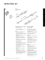
• Rotational shifter with a fixed grip (1),
turning grip (2), shifter body (3), shifter
cable with full cable housing, adjusting
barrel (4) and cable clamp assembly (5).
• Rotating the turning grip shifts the gears,
(2), the selected gear is indicated in the
window (6).
• It is also possible to shift under moderate
pedalling loads
• Under high load, the spring inside the
Clickstick ‘pre-loads’ for the new gear,
allowing the shift only when pedalling
force is reduced. It is important to
downshift before the increased load of
tackling a hill.
• If you do not intend to use your bicycle for
an extended period of time, put the shifter
in gear position “12” in order to reduce
tension in the system. (See Fig. 28.)
SHIFTER CABLE
REPLACEMENT
36
1
Replacing shifter cable – Clickstick
(Fig. 29, 30 and 31)
• Put shifter in gear position “12”
• Open Clickstick by pressing the ribbed
surface of tabs (A) lightly and loosen
cover from element.
• Remove adjusting barrel (4) with nut out of
Clickstick opening and pull the whole
shifter cable in the direction of hub. (It may
be necessary to loosen cable clips to allow
the cable to slide freely.)
• Rotate cable clamp assembly (5) 90° and
unhook it from spring shell (7).
• Loosen clamping bolt (8) and pull cable
out of clamp assembly (5) and adjusting
barrel (4).
• Loosen clamping bolt (9) on the shifter and
slide the complete shifter inwards towards
the middle of handlebar 20 mm or more.
(It may be necessary to loosen and move
brake lever.)
• Separate housing (3) from turning grip (2).
• Slide cable head out of guide (10) and
remove cable.
• Route new cable through shifter housing
and pull cable to seat cable head
completely into cable recess.
• Reassemble shifter by aligning four tabs on
shifter housing with matching recesses on
turning grip and snap together. (Fig. 31)
7
5
4
3 6
37
C
B
D
A
Gear 12
3
38
B
C
4
A
Gear 1
3
D
Caution:
Do not rotate shifter before reconnecting
cable to hub.
• To install shifter, slide shifter onto handlebar, followed by 2 grip washers (11) and
fixed grip (1). The shifter and fixed grip
should be pushed together so the grip
washers are squeezed lightly but the
turning grip rotates easily. Tighten
clamping bolt (9) with a torque of 1.5 Nm
(13 in.lbs.) (3 mm Allen key), position brake
lever and tighten (Fig. 32).
• Slide cable through cable housing and
Technical information may be enhanced without prior notice. Released 10/98.
adjusting barrel (4) with nut.
• Route cable through opening in clamping
bolt (8) and fasten it with a distance of
122.5 mm to adjusting barrel (torque:
1.7–2.5 Nm/15–22 in.lbs.). Cut excess cable
to about 0.5 mm (Fig. 33).
i n s t r u c t i o n s
OPERATION/SHIFTING
Replacing Clickstick – hub cable/
replacing wheel
If the short Clickstick cable is damaged
(spring shell to hub), the rear wheel must be
removed. This entails observing the following
instructions which are also valid for wheel
replacement in the case of a flat tire.
• Disconnect shifter cable from Clickstick by
unhooking cable clamp assembly
(5, Fig. 30)
• Push clip (12) back from chainstay, loosen
or unscrew axle bolts (13), remove
fastening bolt (14) of brake lever clamp
(only for Type MH 12 110), pull wheel from
dropouts and remove chain. (Fig. 34).
For cable replacement, it is a good idea to
clamp the wheel in a vice on the axle
lock nut.
• Remove the crown cover (1) from hub; the
cable head attachment point in the window
opposite the smallest opening is now
visible. (Fig. 35)
• Using a sharp tool, push cable head (2) out
of groove and pull out the cable. (Fig. 35)
• Thread the cable head of the new short
cable (5 with attached spring shell)
through the cable port of the crown cover
opening (1) then secure cable in the hub.
(Fig. 36)
In the following paragraphs, 2 variations
are described.
1st variation: hub in gear 12 (Fig. 37)
• The hub is in gear position 12; insert cable
through the smallest window. Then thread
cable around 1 1/2 times clockwise under
webs A, B, C and D …
Caution:
The cable head must be guided under
cable where the cable crosses itself.
• … guide once more under webs A and B
all the way through to hanger groove (3)
across from smallest window.
• Place cable head and route into opening.
2nd variation: (Fig. 38)
For this procedure the hub is in 1st gear.
• Turn the shifting component via the
window against the spring pressure as
far as the stop.
• Holding in this position, guide cable
through smallest window under webs A
and B.
• The hanger groove (3) is accross from the
smallest window.
• Insert cable head in hanger and pull into
groove (3).
• After cable is installed, pull it and hold it
tightly; to release locating wedge (4) from
gear teeth. (Fig. 38)
31
SPECTRO E12
Advice:
Locating wedge is used
(Ref. No. 2324 001 000 – see Fig. 39)
39
40
1a
1
7
3
4
6
5
41
12
13
• Slowly release cable (this will allow the
spring to wind up the cable and rotate the
gears from 1 through 12)
• Bring Clickstick to hub and position the
crown cover (1) over the shifter crown so
the red arrows on the hub are visible in the
middle of the window (1a). By applying a
little pressure, snap crown cover onto hub
(Fig. 40).
• Slide protective rubber boot (3) over spring
shell (5) and crown cover (1).
• Put cable and spring shell in the groove (6)
on the Clickstick housing.
• Push Clickstick ball end (7) into crown
cover (1). Snap on cover (4) and then
engage lip seals of rubber boot into
grooves on crown cover and Clickstick.
(Fig. 40)
• Fit wheel in rear frame and place chain on
sprocket. (Fig. 41)
• Route ends of axle in the dropout slots,
adjust wheel in frame, mount axle bolts
(13) and tighten with a torque of 30–40 Nm
(266–354 in.lbs.).
Adjustment of shifting (Fig. 44):
• To properly control the cable tension
during gear adjustment, it is necessary to
shift to 1st gear then shift to the 6th gear
adjustment position.
• In the 6th gear position, the two red lines
must line up. Rotate adjusting barrel, as
necessary (4) until the red arrows line up
(16) in window (17).
• Check adjustment from time to time and
readjust if necessary. (Fig. 44).
Caution:
Use original bolts only!
42
• Chain tension is set correctly when the
chain can be lifted about 2 cm in the
middle, between chainring and sprocket.
Snap clamp (12) onto chainstay (Fig. 41).
• Brake lever clamp screw should be
tightened (14) with a torque of 2–3 Nm
(18–27 in.lbs.). (Fig. 42)
Caution:
Brake lever clamp must fit tightly onto frame,
allowing no play.
14
43
5
7
4
4a
15
Connecting shifter cable (Fig. 43):
• Guide cable clamp assembly (5) onto end
of spring shell (7).
• Insert adjusting barrel (4) nut in the recess
(4a) into Clickstick.
• To close cover, slide locking parts (15) in
the openings of Clickstick housing and
snap in. (Fig. 43)
• Adjust shifter cable in the cable clips to
make sure it runs properly along frame and
allows adequate handle-bar rotation.
Tighten cable clips as needed.
To check, shift through all gears
(gear 12–gear 1) with the rotational shifter.
44
17
16
4
32
Technical information may be enhanced without prior notice. Released 10/98.
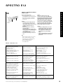
SPECTRO E12
Rotational shifter/Fixed grips
• The rotational shifter consists of three
parts (Fig. 45). The shifter body (3) and the
fixed grip (1) fit snuggly on handlebar,
while the turning grip (2) is fitted into
housing only.
3
1
2
Caution:
• Fixed grips (left and right) provide an
axial safety function. For this reason,
they should be mounted in such a way as
to make sure they do not slip off
handlebar.
• Never use lubricants or solvents to
install fixed grips.
• Never ride without the fixed grips. The
turning grip may loosen from housing and
slip off handlebar – this can result in
severe injury or death.
• The shifter is extensively maintenancefree.
i n s t r u c t i o n s
SAFETY/MAINTENANCE/
SERVICING
45
Caution:
If the coaster brake becomes overly
sensitive or grabs (only for Type MH 12110),
the brake shell should be lubricated with the
designated lubricant (Art.-No. 0369 135 100).
Overheating the hub can lead to lubricant
loss and an overly sensitive or grabby brake.
For this reason, it is imperative to alternately
use the second brake (front wheel brake)
when on long and steep rides. This will give
the rear brake a chance to cool down.
Caution:
• Locking or skidding wheels can cause a
fall which may result in severe injury as
well as damage to the bicycle. To avoid
this, apply pressure on brake lever or
pedals with care to prevent skidding
wheels.
• If the rear wheel develops excessive side
play, have the bearings read-justed by a
professional.
Hub
• When cleaning your bike, do not expose
hub to compressed water (i.e. high
pressure hose, etc.) If water gets into
system, malfunction may occur
• The 12-speed hub has been
factory lubricated.
FAULT CHECK LIST
Problem
Riding (pedaling and freewheeling):
• Different clicking noises
depending on gear
• Vibration noises the same in
all gears (depending on pedal speed)
• Scraping noises after riding in
rain or on sandy paths
• Catching or slipping with noises
Shifting:
• Delayed gear change from 1st–12th
• Delayed gear change from 12st–1th
• Shifting noises when changing gearl
Braking:
• Strong braking action, possibly with
noises, despite low actuating force
• Squeaking noise just before stopping
or when the rear wheel is locked
• Creaking sound the first time
brakes are used after starting off
• Brake does not grip when pedalling
backwards (free travel > 60°)
• Rear wheel locks after braking and
pushing bike backwards
Other:
• Slight resistance when pushing bike
backwards or spinning wheel
Cause
Remedy
• Pawls are overrunning
• If necessary, grease pawl meshing
slightly (not catch base)
• Regrease front of toothed lock t
washer a little bi
• Improves with time, otherwise
remove dust cover and clean
• Check gear position and adjust if necessary
• Axial freewheel (toothed lock
washer) degreased
• Sand grains under dust cover
• fIncorrect gear setting (possibly.
intermediate position at turning grip)
• Control cable in housing stiff or.
restoring spring too weak
• Drive force too great,
shifting protection activated
• Direct catch meshing, aluminum
shell functions as a resonator
• If necessary, reduce pedal pressure
if noise is disturbing
• Brake cylinder grease used up
• Regrease
• Frictional vibration on brake cylinder
• Replace brake cylinder if noise
is disturbing
• Fit clamp without any play
• Replace arm cone assembly
1. Check axial freewheel function
2. Replace friction spring, lining
and tooth/locking disc
• Change into 1st gear or
• Push bicycle vigorously forwards
• Clamp on chainstay is loose
• Torsional play brake lever/lever cone
• Axial freewheel faulty or
incorrectly assembled
• Accidental twisting of brake
caused by gear compensating
• Turn pedals forwards
• Friction spring on axle is moved
Technical information may be enhanced without prior notice. Released 10/98.
• Make sure the control cable runs
easily or renew shifting unit
• Reduce pedal pressure (shift wear-free)
• Normal feature of system. If too strong, fit
new friction springs with axial freewheel assembly
33
SPECTRO S7
SPECIFICATIONS
1
Type H 7215 with coaster brake
Type H 7205 without brake
Type H 7225 with drum brake
The 7 speed gear hub with the unique gear
ratio of 303 % for super-easy cycling. All
gears can be selected directly with a shifter.
Technology, reliability and safety all
correspond with the high levels achieved by
the well-proven Sachs hub gear units.
Shifter in front of handlebars
Shifter behind handlebars
2
TECHNICAL
D ATA / A S S E M B LY
REQUIREMENTS
Advice: Use in tandem is not permitted.
Hub
Total ratio 303 %
3
Cycle frame:
• The strength must be such that with a
maximum torque of 250 Nm on the driving
wheel no residual deformation of the rear
structure will occur.
• When fitting the cable avoid small radii –
route via the bottom bracket, use 28 mm
dia. tube clips for standard frame, Fig. 5 (1)
• Last attachment point is on the lower rear
wheel fork immediately behind the chain
wheel, 20 mm dia. tube clips for standard
frames, Fig. 5 (2)
Ratio:
4
Gear
Ratio
1.
1 : 0.574
2.
1 : 0.677
3.
1 : 0.809
4.
1:1
5.
1 : 1.236
6.
1 : 1.476
7.
1 : 1.742
• Spectro Combi 7 rotational shifter with
integrated brake lever and Mini Clickbox
for adults. Fixing bolt with 4 mm hex socket
head, tightening torque 2.5…3 Nm. (Fig. 3)
• Bandix 7 rotational shifter for children/
young people (driving wheels from 24").
Fixing bolt with 3 mm hex socket head,
tightening torque 1.5 Nm (Fig. 4)
Chain:
Usable chains 1/2" x 1/8"
e.g. Power Chain PC1 or 1/2" x 3/32".
Ratio specification:
Primary 1.83…1.9 for 26" + 28"
Example:
Chain wheel, front T = 44
Rear chain sprocket T = 24
5
Shifter:
Standard shifter consists of:
• humb shifter, in front of/behind
handlebar versions (Fig. 1)
• Push-pull-cable
• Clickbox
Ø Cable housing 4.2 mm
Ø Clip 22…24 mm, tightening torque
of fixing bolts 2.5…3.0 Nm
• Spectro Grip 7 rotational shifter with
Mini Clickbox for adults.
Fixing bolt with 3 mm hex socket head,
tightening torque 1.5 Nm. (Fig. 2)
1
2
Spoke length table
Type
Cross
Tire Size
47–406
37–490
47–507
37–540
47–559
37–590
20" x 1.75 x 2 22" x 1 3/8 24" x 1.75 x 2 24" x 1 3/8 26" x 1.75 x 2 26" x 1 3/8
H 7215/…05 3 x
H 7225
3x
34
181 mm
179 mm
225 mm
222 mm
232 mm
229 mm
251 mm
248 mm
259 mm
256 mm
275 mm
272 mm
47–622
28–622
28" x 1.75
28" x 1 1/8
28–630
27" x 1 1/4 fifty
37–622
32–622
32–630
28" x 1 3/8 x 1 5/8
28" x 1 5/8 x 1 1/4
27" x 1 1/4
289 mm
286 mm
289 mm
286 mm
294 mm
291 mm
Technical information may be enhanced without prior notice. Released 10/98.
SPECTRO S7
i n s t r u c t i o n s
A S S E M B LY D ATA
L1
GW
L3
L2
TK
C
D
E
Ds
T
1/2 GW
10
F1
R
F2
0
Ø 7.3
A 1 max
A 2 max
MH 7215
Coaster brake
NEW
MH 7205
MH 7225
X
Freewheel
X
Drum brake
X
Fork width
GW
130 mm
132 mm
135 mm
Axle length
L1
183.4 mm
183.4 mm
188.5 mm
Axle end, right
L2
33.3 mm
33.3 mm
33.3 mm
Axle end, left
L3
20 mm
18 mm
20.2 mm
8.6 mm
8.6 mm
8.6 mm
Axle thread
T
FG 10.5
FG 10.5
FG 10.5
Max. dropout width dimensions
A1
max
11.5 mm
11.5 mm
11.5 mm
Max. dropout width dimensions
A2
max
12 mm
10 mm
12.2 mm
Smallest poss. sprocket (offset)
Pos. C
16
16
16
Smallest poss. sprocket (straight)
Pos. D
18
18
18
Smallest poss. sprocket (offset)
Pos. E
19
19
19
Chain line (offset)
Pos. C
54 mm
55 mm
55.5 mm
Chain line (straight)
Pos. D
51 mm
52 mm
52.5 mm
Chain line (offset)
Pos. E
48 mm
49 mm
49.5 mm
Axle end 2-flats
Chain ratio
Spoke hole
1.83…1.90 for 26" and 28"
– Number
– Diameter
– Pitch circle dia.
Ds
36
36
36
3.0 mm
3.0 mm
3.0 mm
TK
75 mm
75 mm
90 mm
Spoke flange distance to 1/2 GW
F1
33 mm
34 mm
34.8 mm
Spoke flange distance to 1/2 GW
F2
34 mm
34.5 mm
35.7 mm
Tightening torque on axle nuts
30–40 Nm
Tightening torque
on brake lever clamp
Technical information may be enhanced without prior notice. Released 10/98.
2–3 Nm
2–3 Nm
35
SPECTRO S7
A S S E M B LY
6
2a
1a
• See spoke length table under “Technical
data/assembly requirements” for spoking
the hub.
1
2
Fit dust cap
(optional) (Fig. 6):
2a
• Turn dust cap (1) so that the lugs (1a) are
positioned between the three recesses (2a)
on the sprocket (2).
• Position dust cap (1) and push it towards
the sprocket (2) until it can be felt to
engage.
• After positioning the wheel in the rear fork
fit non-turn washer (4, Fig. 7) to the outside
of the dropout on the brake lever side. The
serrations must bear against the dropout
and the lug must engage in the dropout
slot.
• On the sprocket side fit the protective
bracket (1, Fig. 10) directly below the fixing
nut. Tightening torque on acorn or hex nuts
approx. 35 Nm.
• Fit brake lever tube clamp
(5, Fig. 7) Tightening torque: 2 – 3 Nm.
Caution:
The clamp must be seated on the frame
with no play.
2a
7
4
5
8
Shifter adjustment is also unnecessary
following re-assembly!
Shifter setting for the rotational shifter/
Mini Clickbox version:
See “Assembly of rotational shifter/exchange
of control cables/shifter adjustment ”.
Advice:
Conversion to the Mini Clickbox version is
possible without the need to exchange shift
rod/tube or locating sleeve.
Removal of rear wheel:
• Loosen knurled bolt
• Pull off clickbox
• Remove locating sleeve,
shift tube/rod
• Take out wheel as normal
Advice:
If a different protective bracket is used the
thickness of the attachment plate must be
max. 3 mm. Do not use additional washers. A
minimum of 1 thread turn X must be visible in
front of the axle nut (see Fig. 8)!
Caution:
Max. width of inserts under left axle nut
(brake lever side) type 7215 11.5 mm, type
7205 11.5 mm, type 7225 11.5 mm. Max. width
of inserts under right axle nut (drive side)
type 7215 12 mm, type 7205 10.0 mm, type
7225 12.2 mm.
X
9
Axle
Axle bore
Slot for lug on
locating sleeve
Guiding rib
Lug
Slot for
knurled bolt
2
3
4
10
1
2
3
36
Next: (see Fig. 9)
• Insert shift rod (3) in shift tube (4) (oil
parts lightly) and then push into axle
bore as far as the stop. Turn slot in shift
tube to a position where it is easily visible.
• Push locating sleeve (2) with guiding rib to
the front onto the hub axle – making sure
that the internal lug is guided in the slot of
the shift tube until it can be felt – and
heard – to engage.
• Turn locating sleeve on the axle until the
guiding rib is facing roughly upwards.
• Push on clickbox (2, Fig. 10) to the stop on
the hub axle. The guiding rib of the locating sleeve thereby engages in the slot on
the housing. In the end position tighten up
the knurled bolt (3, Fig. 10) by hand.
Assembly can be performed independently
of the gear setting but it is best done at
shifter position “1”.
Shifter setting for the thumb shifter/
clickbox version:
Shifter adjustment is not necessary!
Technical information may be enhanced without prior notice. Released 10/98.
SPECTRO S7
i n s t r u c t i o n s
Fig. 11:
Exploded drawing
Assembling/dismantling
the hub
12
78
32
6
31
30
5
4
3
X
2
1
18
19
20
17
21
23
22
24
25
26
27
29
28
41
42
16
X
15
10
11
12
13
40
39
14
38
37
35
9
36
34
33
DISMANTLING THE HUB
H U B A S S E M B LY
(see exploded drawing)
(see exploded drawing)
• Remove circlip (38) (Fig. 11), sprocket (37)
and dust cap (36) as normal.
• Insert into the axle (on the side with the
internal thread) one after the other:
• Short compression spring (20, Fig. 11,
“Dismantling the hub”)
• Thrust block (19) – it is the same both sides
• Guide rod (18) –it is the same both sides
• Long compression spring (17)
• Press spring together and fit grub
screw (16)
• Clamp axle with crank for clickbox facing
upwards
• Fit plastic profile washer (21) with its large
diameter upwards
• Fit thrust washer (22) and crescent-shaped
retaining washer (23)
• Locate conical cap * (24),compression
spring (25) with 7 turns, conical cap * (26).
• Press spring together and position thrust
block (27) – it is the same both sides –
centrally in the axle.
• Reclamp axle (with crank downwards)
Next:
• Withdraw locating sleeve (42) (latched)
• Take out shift rod/tube (40/41)
• Clamp hub by the axle between aluminium
jaws with sprocket side facing downwards.
• Unscrew both locknuts (1)
• Remove lever cone (2) ball retainer (3) and
brake shell (4)
• Withdraw hub sleeve (5) upwards
• Unscrew brake cone (6) from flat thread
• Take out retaining washer (7) and thrust
washer (8).
• Remove planetary gear carrier (9), washer
(10) compression spring (11) and the three
sun gears (12, 13, 14).
• Reclamp hub by the axle
• Unscrew fixed cone (35)
• Remove driver (34), compression spring (32)
with conical cap (31), large compression
spring (30), ball retainer (33), ring gear (29)
and coupling gear (28)
• Press spring (25) together and remove
thrust block (27).
• Remove conical cap (26), spring (25) and
conical cap (24)
• Dismantle crescent-shaped retaining
washer (23)
• Remove thrust washer (22) and plastic
profile washer (21)
• Unscrew grub screw (16) (Caution: It is
subject to spring pressure) – and diamantle
the long compression spring (17) guide pin
(18), thrust block (19) and the short
compression spring (20)
Technical information may be enhanced without prior notice. Released 10/98.
Thereafter:
• Fit large sun gear (14), with deflector
bevels upwards.
• Position medium sun gear (13), with
deflector bevels upwards.
• Fit small sun gear (12) – with recesses in
front, thrust block engages in the slots.
• Position smallest compression spring (11)
• Fit 1 mm thick washer (10)
• Fit planetary gear carrier (9).
In doing so: Place the mounting aid (Fig.
12) on the planetary gear carrier such that
the markings (X) on the 3 small planet
gears and the mounting aid match up.
• Turn planetary gear carrier and at the same
time push it downwards over the sun gears.
• Fit thrust washer (7) and
• fit retaining washer (8) in the undercut.
37
SPECTRO S7
Only now should you remove the
mounting aid
13
Advice:
If the gears are not accurately assembled the
hub may feel tight in use. This may lead to
sprocket damage during travel.
6
9
8
7
• Reclamp axle (clickbox crank facing
upwards again)
• Fit coupling gear (28) with carrier plate
downwards
• Push ring gear (29) over the coupling gear.
• Locate large spring (30)
• Fit largest ball retainer (33) with balls
underneath
• Fit conical cap (31)
• Assemble the compression spring (32) with
12 turns
• Position driver (34) – push it down – and
• screw on fixed cone (35) to the stop,
tightening torque 20 Nm.
• Reclamp axle (clickbox crank facing
downwards again)
• Screw brake cone (6) onto the flat thread
• Assemble hub sleeve – with a slight
counter-clockwise movement over
the pawl ratchet.
• Insert brake shell (4)– retaining lugs
upwards, thereby the friction spring on the
brake cone must engage in the slot on the
brake shell.
• Locate ball retainer (3) (balls underneath),
position lever cone (2), thereby turn it
clockwise until the retaining lugs engage.
• Screw on locknuts (1), adjust bearing so
that there is no play and lock nuts together
with 15–20 Nm.
14
*
1
15
4
3
5
Advice:
The assembly of the hub types
H 7205/H 7225 should be carried out in the
same way. Difference: Instead of brake
shell/cone a click-and-pawl carrier is
installed on the planetary gear carrier here.
Without flat thread – fixed with a retaining
washer. Type 7225 – Exchange of brake
anchor plate and brake adjustments, see
Point “Type H 7225/Drum brake”
2
16
2 +1 mm
68.5 ± 0.5 mm
*
5 mm
6
5
A S S E M B LY O F
ROTATIONAL SHIFTER/
EXCHANGE OF
CONTROL CABLE/
SHIFTER ADJUSTMENT
17
Dismantling the shifter cable:
(Applies to the Spectro Grip 7/Bandix 7/
Spectro Combi 7)
• Lever off cap (1, Fig. 14) on shifter housing.
• Put rotational shifter in 1st gear. (The
cable head of the shifter cable must be
visible in the opening).
• Unscrew bolt (2, Fig. 15), remove cap (3).
• Withdraw shifter cable and clamping bolt
(6) upwards, loosen clamp and pull
clamping piece from cable. (Fig. 17)
Control cable:
• Insert shifter cable through viewing
window in gear position “1” (Fig. 14). –
Pull shifter cable out through opening in
shifter.
Caution:
Only use shifter cables with a diameter of
1.35 mm art. no. 0391 007 004.
• Screw in completely the adjusting screw
on rotational shifter.
• Position clamping bolt (6) at a distance of
68.5 mm, tighten up with 1.5 Nm and cut off
cable ends to 2…3 mm (see Fig. 16).
• Fig. 17: Locate clamping bolt (6) and place
shifter cable around the carrier cylinder
(anti-clockwise winding).
• Insert the square nut of the adjusting bolt
(5) in the housing and completely screw in
the knurled bolt.
Adjustment:
• Be sure to reset rotational shifter from 5th.
to 4th gear
• Position cap (3) and tighten up with
bolt (2).
• Make sure that the cap on the twistgrip
(1, Fig. 14) engages in the shifter housing.
• Match up the arrow marks in the viewing
window (4) of the cap (3) by turning the
adjusting screw (5).
Check the setting from time to time and
readjust as necessary.
Advice:
To set the clamping bolt –
adjusting screw distance a setting piece can
be used. Order no. 0324 105 000
(Mini Clickbox)
6
5
38
Always fit the inside of the conical
cap to the spring
Advice:
Do not fit right or left-hand fixed grips (8)
onto the handlebars with greasy materials.
Assemble rotational shifter (Fig. 13):
• Push shifter (6) onto handlebar
• Slide on two thrust washers (7)
• Fit fixed grip (8) onto handlebar end
• Place shifter (6) against fixed grip (8).
• Align shifter (6) on the handlebars and
tighten up with bolt (9).
Tightening torque 1.5 Nm
Technical information may be enhanced without prior notice. Released 10/98.
SPECTRO S7
Instal brake anchor plate
(or exchange it) Fig. 18
• Place thrust washer (3) over the axle on
the adjusting cone and fit complete brake
anchor plate. Position washer (4) distance
sleeve (5) and screw on locknut (6). Push
brake lever (7) to the stop and hold it there
to center the brake jaws in the brake
drum – tighten up locknut with a torque of
15…20 Nm.
1
2
4
6
5
3
7
Brake adjustment (Fig. 18)
• Unscrew adjusting screw (1) until the
brake lightly touches the wheel when it is
turned.
• Operate the hand brake lever several times
forcefully and then turn the adjusting
screw further as necessary until the brake
lightly touches the wheel again.
• Lock the hex nut (2)
• Repeat adjustment operation if the braking
effect is reduced after lengthy use or if the
hand brake lever can be pulled back to the
handlebar grip.
.
MAINTENANCE/
SERVICING
• The Spectro S7 is provided with
permanent lubrication and under normal
conditions is maintenance-free. If the
brake is loaded excessively its effect can
be too strong. In such a case the brake
shell should be lubricated with a special
grease. Keep the pawl pockets free from
grease. (Art. no. 0369 135 100)
After completely dismantling the hub the
following items should also be noted:
1. Cleaning of parts:
• All parts – except for the planetary gear
carrier – can be degreased in a cleaning
bath.
• The planetary gear carrier only needs to
be cleaned on the outside with a brush so
as not to degrease the planetary gear
bearing.
i n s t r u c t i o n s
TYP H 7225
(DRUM BRAKE)
18
2. Lubrication of parts:
• To lubricate the bearing points on the
planetary gear sets, position the planetary
gear carrier on its crown and apply 2–3
drops of oil to the bearing bolts – at the
same time turning the planetary gears so
that the bearing points are completely wet.
Oil axle through the axle bore and axle
slot, apply a thin coating of grease to the
outside.
• Oil the inside of the sun gears, grease the
outside teeth (fill the gaps in the teeth).
• Oil outside teeth and carrier plate on
the coupling gear and lightly grease the
borehole from right and left.
• Do not apply grease to ring gear but just
oil the pawl pockets.
• Grease the brake cone in the borehole and
the friction spring.
• Spread grease on the inside and outside of
the brake shell.
• Regrease ball retainer, line ball bearing
running tracks with grease.
• Fill lever cone with grease reserves for
brakes
Advice:
• If the cycle is not used for a long period
put the shifter into gear position “1” to
reduce the strain on the system.
• Hub gears should not be subjected to
high-pressure water during cleaning (e.g.
strong water jet, high-pressure cleaner
etc.) – any water which penetrates could
lead to functional problems.
TROUBLE SHOOTING
Problem
Likely cause
Corrective action
Pedals are carried forward
when freewheeling
• Bearings adjusted
too tightly
• Loose locknuts
• Chain tension too tight
• Re-adjust bearings
• Tighten locknuts
(15–20 Nm)
• Reduce chain tension
Pedals slowly give when
braking – only type 7215
(does not impair safety)
• Brake cone/
brake shell
• Exchange brake cone
and brake shell
Hub locks during braking
• only type 7215
• Brake shell run dry
• Wash hub shell clean,
emery the brake cylinder
surface, lubricate (see
“Maintenance/servicing”),
exchange brake shell
Technical information may be enhanced without prior notice. Released 10/98.
39
SPECTRO P5
Type H 5215 with coaster brake
Type H 5205 without brake
Type H 5225 with drum brake
1
TECHNICAL DATA/
A S S E M B LY
REQUIREMENTS
Advice:
Type H 5205 is authorized for use in tandem.
Hub:
Total ratio: 251 %
2
Ratio:
Gear
Ratio
1.
3
5
6
1
40
1 : 0.78
3.
1:1
4.
1 : 1.28
5.
1 : 1.58
Spoke length table:
4
2
1 : 0.63
2.
Ratio specifications:
• Primary 1.8…1.9 for 26" + 28"
• Example:
Front chainwheel
T = 44
Rear chain sprocket T = 24
Type
Cross
L
Tire Size
H 5215/…05
H 5225
3x
3x
181 mm
179 mm
47–406
20" x 1.75 x 2
H 5215/…05
H 5225
3x
3x
225 mm
222 mm
37–490
22" x 1 3/8
H 5215/…05
H 5225
3x
3x
232 mm
229 mm
47–507
24" x 1.75 x 2
H 5215/…05
H 5225
3x
3x
251 mm
248 mm
37–540
24" x 1 3/8
H 5215/…05
H 5225
3x
3x
259 mm
256 mm
47–559
26" x 1.75 x 2
H 5215/…05
H 5225
3x
3x
275 mm
272 mm
37–590
26" x 1 3/8
H 5215/…05
H 5225
3x
3x
289 mm
286 mm
47–622
28" x 1.75
37–622
28" x 1 3/8 x 1 5/8
H 5215/…05
H 5225
3x
3x
289 mm
286 mm
28–622
28" x 1 1/8
32–622
28" x 1 5/8 x 1 1/4
H 5215/…05
H 5225
3x
3x
294 mm
291 mm
28–630
27" x 1 1/4 fifty
32–630
27" x 1 1/4
Shifter:
Standard shifting system consists of:
• Thumb shifter, 2 versions designed for in
front of/behind handlebars
• Push-pull-cable
• Clickbox
• Ø Cable housing, 4.2 mm
Ø Clips, 22…23.5 mm,
tightening torque of fixing screws
2.5…3.0 Nm
• Thumb shifter (for push-pull clickbox), in
front of handlebars version (Fig. 1)
• Thumb shifter (for push-pull clickbox),
behind handlebars version (Fig. 2)
• Spectro Grip 5 rotational shifter, with
Mini Clickbox for adults (Fig. 3)
• Spectro Combi 5 rotational shifter with
integrated brake lever and Mini Clickbox
for adults (Fig. 4)
• Bandix 5 rotational shifter, for children/
young people (from 24" wheel size), (Fig. 5)
Cycle frame:
• The strength must be such that with a max.
torque of 250 Nm on the driving wheel no
residual deformation can occur on the rear
structure.
• When installing the cable avoid small
radii – route via bottom bracket, tube clips
of 28 mm dia. for standard frame, Fig. 6 (1)
• Last attachment point is on lower rear fork
immediately behind the chainwheel, tube
clips of 20 mm dia. for standard frame,
Fig. 6 (2)
Chain:
Permitted chains 1/2" x 1/8" e.g.
Power Chain PC1 or 1/2" x 3/32".
Technical information may be enhanced without prior notice. Released 10/98.
SPECTRO P5
i n s t r u c t i o n s
A S S E M B LY D ATA
L1
GW
L3
C
D
E
TK
Ds
T
1/2 GW
L2
Ø 7.3
F2
F1
R1
A 2 max.
NEW
A 1 max.
MH 5215
Coaster brake
Freewheel
Drum brake
MH 5205
MH 5225
X
X
X
Fork width
Axle length
Axle right
Axle left
Axle end 2-flat
Axle thread
Max. Dropout width dimensions
Max. Dropout width dimensions
GW
L1
L2
L3
8.6
T
A 1 max
A 2 max
Smallest sprocket (offset)
Smallest sprocket (straight)
Smallest sprocket (offset)
Chain line (offset)
Chain line (straight)
Chain line (offset)
Pos.
Pos.
Pos.
Pos.
Pos.
Pos.
C
D
E
C
D
E
122
175
33.5
19.5
8.6
FG 10.5
11.5
11.5
123
175
33.5
18.5
8.6
FG 10.5
11.5
10.5
FG 10.5
11.5
12.5
16
17
18
49
45.5
43
16
17
18
49.5
46
43.5
16
17
18
51.5
48.5
45.5
Chain ratio
• Number
• Diameter
• Circle diameter
Spoke flange distance to 1/2 GW
Spoke flange distance to 1/2 GW
00
126
179
32.5
20.5
1.8…1.9 for 26" and 28"
Spoke hole
Ds
TK
F1
F2
Torque on axle nut
Torque on on brake lever clamp
36
3.0
75
28.5
29.5
36
3.0
75
29.0
29.0
36
2.8
90
30.5
29.5
30…40 Nm
2…3 Nm
30…40 Nm
30…40 Nm
2…3 Nm
Dimensions in mm
Technical information may be enhanced without prior notice. Released 10/98.
41
SPECTRO P5
A S S E M B LY
7
2a 1a
• For insertion see spoke length table
under “Technical data”
1
2
Fit dust cap (optional, Fig. 7)
• Turn dust cap (1) so that the lugs (1a) are
located between the three ridges (2a) on
the sprocket (2).
2a
Fitting the wheel
• Put dust cap (1) in place and push
towards the sprocket (2) until
engagement is felt.
• Fit wheel in rear fork, fit non-turn washers
(3, Fig. 8) on both sides. The serrations
must bear against the outside of the
dropouts and the prongs must engage in
the dropout slots.
2a
8
Advice:
If a chain tensioner is provided fit the nonturn washers (3) so that the serrations bear
against the inside of the dropouts. The fixed
cone (drive side) must always directly bear
against the dropouts.
4
5
• Fit protective bracket (4, Fig. 9) directly
below the axle nut on the sprocket side.
• Tightening torque of axle nuts, approx.
35 Nm.
• Fit brake lever clamps (5, Fig. 8)
• Tightening torque: 2–3 Nm.
9
Caution:
The clamps must be seated on the frame
so that there is no play.
4
Thumb Shifter/Clickbox
(Standard version):
• Fit shift rod (5, Fig. 10) on shift tube (6)
(lightly oil all parts) and push into axle
bore to the stop. Apply slight pressure on
the shift rod with its threaded section and
screw inwards in a clockwise direction
until it can again be moved axially.
• Push Clickbox onto the hub axle as far as
10
the stop. Then make sure that the knurled
bolt engages the slot on the hub axle when
tightened up. It is not necessary to adjust
the shifter.
Mini Clickbox (see Fig. 11):
• Assembly of shift rod (8, without head)
and shift tube (9, with slot) is the same as
the standard version.
• First push the adjuster barrel (13) with
guiding rib (12) onto the hub axle – making
sure that the lug (10) is guided into the slot
on the shift tube (11) – until it can be felt to
engage. Turn guiding rib (12) to face
upwards.
• Push Clickbox to the stop on the hub axle.
The guiding rib (12) should then be fully
seated in the slot on the Clickbox housing.
For both versions the following applies:
• After fitting the Clickbox tighten up the
knurled bolt by hand making sure that the
knurled bolt engages with the slot in the
hub axle. Assembly can be carried out
independently of the shifter setting but it is
easiest to assemble the Clickbox in 2nd
gear (without the need to overcome spring
pressure).
Advice:
Shifter adjustment or retroadjustments are
only necessary with the Mini Clickbox. Carry
out adjustment work or check settings after
changing a wheel (e.g. after a flat tire).
Removal of rear wheel:
• Loosen knurled bolts
• Withdraw clickbox, the shift rod/tube can
be left in the hub axle without being lost.
To remove both parts pull shift rod outwards and unscrew in an counter-clockwise direction.
• Remove wheel as normal.
6
5
7
Differences between the push-pull
clickbox and the Mini Clickbox
(see also Figs. 10 and 11)
11
Thumb Shifter/
Clickbox/Push Pull
11
12
Shift tube
Gray, without slot
Silver color, with slot
Shift rod
Dark gray, with head
and a thread
121.5 mm lg
Copper colored, without head,
with two threads 113.8 mm lg.
Locating sleeve
None
Included
Shifter adjustment
No
Yes, see “Shifter adjustment”
9
8
13
42
10
Rotational shifter/
Mini Clickbox
Technical information may be enhanced without prior notice. Released 10/98.
SPECTRO P5
i n s t r u c t i o n s
Figure 12: Exploded view
13
78
6
29
5
28
4
27
3
2
1
X
14
X
15
16
17
18
20 21
19
22
26
24 25
23
38
11
41
40
13
10
39
35
12
36 37
34
9
30
32 33
31
DISMANTLING THE HUB
A S S E M B LY O F H U B
(see exploded view, Fig. 12)
(see exploded view, Fig. 12)
• Remove circlip (35), sprocket (34) and
dust cap (33).‘
• Clamp hub with sprocket side facing
downwards with the two axle flats.
• Unscrew the two locknuts (1).
• Remove lever cone (2), ball retainer (3)
and brake shell (4).
• Withdraw hub sleeve upwards.
• Unscrew brake cone (6) from flat thread.
• Remove retaining washer (7), thrust
washer (8).
• Remove planetary gear carrier (9) and
thrust washer (10).
• After this clamp hub in a vise.
• Unscrew fixed cone (32).
• Remove driver (31), compression spring
(29), large compression spring (27) and ball
retainer (30). – Wihdraw ring gear (26) and
coupling gear (25) and then remove conical
cap (23) from the coupling gear.
• Take out thrust block (24), (to do this press
the spring together). Remove spring (22)
and the two conical caps (23/21).
• Dismantle retaining washer (20), washer
(19), conical compression spring (18),
and the large sun gear (12). Reclamp
axle, (thrust block visible).
• Unscrew grub screw (14)
(Caution: It is subject to spring pressure) –
Dismantle spring (15), guide bolt (16) and
thrust block (17).
• Remove small sun sun gear (11).
• Clamp axle with internal thread upwards.
• Position small sun gear (11) with crown
gears to the front.
• Position thrust block (17) in the slotted
hole (is laterally guided when the sun
gear is screwed in).
• Locate bolt (16), then spring (15) in the
axle and screw in grub screw (14) until
it is flush with the axle.
• Reclamp axle. Fit large sun gear (12) (it is
the same both sides). Position conical
compression spring (18), with the large
diameter first. Press spring together and fit
washer (19) and retaining washer (20).
• Assemble conical cap *) (21), compression
spring with 7 turns (22) and the second
conical cap *) (23).
• Press spring together and position thrust
block (24) (it is the same both sides) in the
center of the slotted hole.
• Position coupling gear (25) with carrier
plate facing downwards.
• Fit conical cap *) (28) for compression
spring.
• Position ring gear (26) over the teeth of
the coupling gear.
• Place ball retainer (30), with balls below
on the ring gear.
• Position large compression spring (27)
on ring gear.
• Mount compression spring with 13 turns
(29) on the axle. (Is supported in the
coupling wheel by the conical cap).
• Locate driver (31), press it down and screw
on fixed cone (32) as far as the stop.
Tightening torque 20 Nm. (Then reclamp
hub in vise).
• Push on thrust washer (10) and fit
planetary gear carrier (9). In doing this:
Position mounting aid (Fig. 13) on the
planetary gear carrier so that the (X)
markings on the threeplanetary gears
match with the mounting aid.
Hub types H 5205/H 5225 should be
dismantled in the same way. Difference:
Instead of the brake shell/-cone,
a click-and-pawl carrier is mounted
on the planetary gear carrier here.
For cleaning and lubrication see
“Maintenance/servicing”.
Technical information may be enhanced without prior notice. Released 10/98.
*) Always mount inside of cone to the spring.
43
SPECTRO P5
• Insert planetary gear carrier, place
thrust washer (8) on it and mount
retaining washer (7) in recess.
Only now should you remove the
mounting aid.
14
6
9
8
7
Advice:
If the gears are not accurately installed
the hub may be tight to move.
This could lead to damage to the gearwheels
in operation. For lubrication of the hub see
“Maintenance/servicing”.
15
1
16
4
3
The assembly of hub types H 5205/H 5225
should be carried out in the same way.
Difference: Instead of the brake shell /-cone
a click-and-pawl carrier is installed here on
the planetary gear carrier. Without flat
threads – fixed with a retaining washer.
5
2
A S S E M B LY O F
ROTATIONAL SHIFTER/
EXCHANGE OF
CONTROL CABLES/
ADJUSTMENT OF
SHIFTER
17
2 +1 mm
• Screw brake cone (8) onto flat threads.
• Mount hub sleeve (5), with a slight
counter-clockwise turn overe the pawl.
• Locate brake shell (4) – with retaining lugs
uppermost –, then the friction spring on the
brake cone must engage with the slot on
the brake shell.
• Insert ball retainer (3) – with balls below.
• Position lever cone (2) – in doing this
turn it clockwise until the retaining
lugs engage.
• Screw on counternuts (1), adjust bearings
to be free of play and tighten lock nuts.
Tightening torque 15–20 Nm.
68.5 ± 0.5 mm
(Mini Clickbox)
5 mm
3
4
Assemble rotational shifter (Fig. 14):
• Push shifter (6) onto handlebars
• Push on two thrust washers (7)
• Mount fixed grip (8) onto ends
• Place shifter (6) against fixed grip (8).
• Align shifter (6) on handlebars and tighten
up using bolt (9).
Tightening torque 1.5 Nm
18
6
Advice:
Do not fit fixed grips (8) on both the right and
left of the handlebars with greasy materials.
19
1
2
6
5
4
3
7
44
Dismantling the shifter cable:
(Valid for Spectro Grip 5/Bandix 5/
Spectro Combi 5)
• Lever off cap (1, Fig. 15) from shifter
housing.
• Set rotational shifter to 1st gear. (Cable
head on the control cable must be visible
in the opening).
• Unscrew bolt (2, Fig. 16), remove cap (3).
• Withdraw shifter cable and clamping bolt
(6) upwards, loosen clamp and pull clamp
from cable. (Fig. 18)
Assembly of shifter cable:
• In gear position “1” insert shifter cable
through sight window (Fig. 1) – pull shifter
cable out through opening in shifter.
Caution:
Only use shifter cables with dia. of 1.35 mm
article no. 0391 007 004
• Screw in adjusting screw on the
rotational shifter completely.
• Position clamping bolt (6) at a spacing of
68.5 mm, tighten up with a torque of 1.5 Nm
and cut off cable ends to 2…3 mm.
(see Fig. 17)
• Fig. 18: Insert clamping bolt (6) and place
shifter cable around the carrier cylinder
(counter-clockwise winding direction).
• Insert the square nut of the adjusting
screw (5) in the housing and screw in the
knurled bolt completely.
Adjustment:
• Be sure to reset rotational shifter from
4th to 3rd gear
• Position cap (3) and tighten up with
bolt (2).
• Make sure that the cap on the twistgrip
(1, Fig. 1) engages in the shifter housing.
• Match up the arrow marks in the viewing
window (4) of the cap (3) by turning the
adjusting screw (5).
From time to time check the setting and
readjust as necessary.
Advice:
To set the clamping bolt – adjusting screw
distance, a setting piece can be used.
Order no. 0324 105 000
TYP H 5225
(DRUM BRAKE)
Instal brake anchor plate (or exchange it)
Fig. 19:
• Place thrust washer (3) over the axle on
the adjusting cone and fit the complete
brake anchor plate. Position washer (4)
and distance sleeve (5) and screw on the
locknut (6). Push brake lever (7) as far as
the stop and hold it tight to center the
brake jaws in the brake drum – tighten up
the locknut with a tightening torque of
15…20 Nm.
Brake adjustment (Fig. 19):
• Unscrew adjusting screw (1) until the
brake lightly touches the wheel when
turning.
• Forcefully operate the hand brake lever
several times and then turn the adjusting
screw further as necessary until the brake
begins to touch the wheel again.
• Lock the hex nut (2).
• Repeat adjustment operation if after
lengthy use the braking effect is reduced
or the hand brake lever can be pulled
back to the handlebar grip.
Technical information may be enhanced without prior notice. Released 10/98.
SPECTRO P5
• The Spectro P5 is provide with permanent
lubrication and under normal conditions is
maintenance-free. If the coaster brake is
loaded excessively its effect can be too
strong. In such a case the brake shell
should be lubricated with a special grease
(art. no. 0369 135 100).
After dismantling the hub the following
items should be carried out:
• Oil axle through the axle bore and lightly
grease the outside.
• Lightly grease the inside teeth on the ring
gear – but only oil the pawl pockets.
• Oil coupling gear and carrier plate
assembly on both sides, do not grease.
• Only clean the planetary gear carrier with
a brush (do not put in cleaning bath)
• To lubricate the bearing points on the
planetary gear sets position the planetary
gear carrier on its crown and apply
2–3 drops of oil to the bearing bolts – while
doing this turn the planetary gears so that
the bearing points are completely wetted.
Grease bearing points etc. as normal and
provide lever cone with a grease supply.
i n s t r u c t i o n s
MAINTENANCE/
SERVICING
Advice:
• If the cycle is not used for a lengthy
period, set shifting lever to gear position
“2” so that the system is not strained.
• Do not use high-pressure water when
cleaning the hub gear unit (e.g. strong
water jets, high-pressure cleaners etc.) –
if water penetrates the unit it could lead
to functional problems.
TROUBLE SHOOTING
Problem
Cause
Corrective action
Difficulty in shifting
Pedals rotate forwards
when freewheeling
• Damaged control cable
• Bearing set too tight
• Loose locknuts
• Replace control cable
• Reset bearing
• Tighten locknuts
(15 –20 Nm)
• Reduce chain tension
Pedals slowly give
when braking –
only type H 5215 (this
does not impair safety)
• Brake cone/brake shell
• Exchange brake cone
and brake shell
Hub locks when braking –
only type H 5215
• Brake shell has run dry
• Wash out hub sleeve,
repolish and relubricate
brake cylinder, renew
brake shell
• Chain tension set too high
Technical information may be enhanced without prior notice. Released 10/98.
45
SPECTRO T3
1
SPECIFICATIONS
Type H 3115 with coaster brake
Type H 3105 without brake
Type H 3125 with drum brake
The ideal drive for city and recreational
bikes – simple to operate and adjust with
precise gear selection using a variety of
shifters. The Spectro T3-hub is practically
maintenance-free.
TECHNICAL DATA
Advice:
The hub is not suitable for tandem use.
Technical data:
2
Total ratio:
186%
1st gear (hill gear)
Ratio 1 : 0.73
(– 27%)
2nd gear (normal gear)
Ratio 1 : 1
3rd gear (fast gear)
Ratio 1 : 1.36
(+ 36%)
Distance travelled by one pedal revolution
(example):
Gear
1
2
3
3,89 m
5,33 m
7,24 m
Handlebar shifter:
• Spectro Click 3 (Fig. 1)
• Handlebar diameter 22.0…22.4 mm
• Fixed grip diameter in shifter area max.
33 mm
• Select a brake lever that allows the
shifter to function correctly
3
Caution:
This shifter uses a derailleur cable with a
Ø 3 mm head and 3 mm length.
Rotational shifter:
• Spectro Grip 3 (Fig. 2) with left dummy grip
• Handlebar diameter 22.0…22.4 mm
• Length of the straight required handlebar
end min. 145 mm + width of the brake
lever clamp
Rotational shifter:
• Bandix 3 for kids (Fig. 3)
• Handlebar diameter 22.0…22.4 mm
• Length of the straight required handlebar
end min. 125 mm + width of the brake
lever clamp
46
Technical information may be enhanced without prior notice. Released 10/98.
SPECTRO T3
L1
GW
L3
i n s t r u c t i o n s
A S S E M B LY D ATA
TK
L2
C
D
E
Ds
T
1/2 GW
Ø 7.3
A 1 max
A 2 max
F2
F1
R
10
0
NEW
Bike frame:
• For brake hubs, the rear frame must be
designed so that there is no lasting
deformation of the chainstay at a wheel
torque of 250 Nm (184 ft.lbs.).
Primary ratio:
(Number of teeth on chainring divided by
number of teeth on sprocket = primary ratio)
26" wheels 2.0…2.4
28" wheels 2.0…2.4
Chain:
• Roller chain 1/2" x 1/8" oder 1/2" x 3/32"
(depending on the thickness of the
sprocket used).
3 speed hubs
MH 3115
Coaster brake
w/o brake
Drum brake for disc brakes
MH 3125
X
X
X
Over locknut dim.
Axle length
Axle right
Axle left
Axle end 2-flat
Axle thread
Max. dropout width dimensions
Max. dropout width dimensions
T
A1
A2
Smallest sprocket (off-set)
Smallest sprocket (straight)
Smallest sprocket (off-set)
Chain line (off-set)
Chain line (straight)
Chain line (off-set)
Pos.
Pos.
Pos.
Pos.
Pos.
Pos.
GW
L1
L2
L3
max
max
C
D
E
C
D
E
118
152/164
17.7/22.2
16.3/23.8
8.6
FG 10.5
9.7/14.2
8.3/15.8
117
152/164
17.7/22.2
17.3/24.8
8.6
FG 10.5
9.7/14.3
9.5/14.0
118
164
22
24
8.6
FG 10.5
14
16
16
16
16
44.5
41.5
38.5
16
16
16
44
41
38
16
16
16
44.5
41.5
38.5
Chain ratio
– Number
– Diameter
– Circle diameter
Spoke flange distance to 1/2 GW
Spoke flange distance to 1/2 GW
MH 3105
2.0…2.4 for 26" + 28"
Spoke hole
Ds
TK
F1
F2
Torque on axle nut
Torque on
Brake lever frame clamp
28/36
3.0
58
24.5
25.5
36
3.0
58
24.5
25.5
36
2.8
89
25.5
32.5
30…40 Nm
30…40 Nm
30…40 Nm
2…3 Nm
2…3 Nm
Dimensions in mm
Technical information may be enhanced without prior notice. Released 10/98.
47
SPECTRO T3
SYSTEM COMPONENTS/
ACCESSORIES
4
Three speed hub with accessories
(see also assembly data))
• Spectro Grip 3 with left dummy gripi
(Fig. 4)
• Bandix 3 with left dummy grip (Fig. 5)
• Spectro Click 3 (1, Fig. 6)
• Shifting cable (2) for Spectro Click 3
(cable head Ø 3 mm/length 3 mm)
and shifting cable push pull for
Spectro Click 3 Ø 6 mm (Fig. 6)
• Locating sleeve (3) and locating sleeve
with clamping device (3a, Fig. 6)
• Cable stop clamp with retaining strap
(4, Fig. 6)
• Cable pulley clamp with retaining strap
(5, Fig. 6)
• Brake lever clamp (6, Fig. 7)
• Bike clip with retaining strap or direct
assembly (Fig. 8)
• Chain 1/2" x 1/8"
1/2" x 3/32"
5
A S S E M B LY
6
1
1
3
4
5
2
3a
7
6
8
• Spoke the hub as normal.
• Place the dust cap and sprocket
on the driver.
• Push sprocket circlip 4 onto the cone
of tool sleeve 5. Place tool sleeve 5 with
large diameter on the driver.
• Push the spring end of sliding sleeve 6
of the tool over the tool sleeve. Thrust
sliding sleeve 6 in direction y, this forces
circlip 4 into the recess of the driver
(Fig. 9) – Remove tool 5/6 and check that
the circlip is seated correctly.
• Turn dust cap (1, Fig. 11) until the three
lugs (1a) are between the three beads (2a)
on the sprocket (2).
• Position dust cap (1) and push towards
sprocket (2) until it is felt to lock into
place. (Fig. 11)
• Placing the wheel in the rear frame
• Fit the chain
• Guide the axle ends into the slot of
the dropouts
• Fit retaining washers (1) on the two ends.
The teeth must face outwards at the dropout, the prongs must catch in the dropout
(Fig. 10). Tighten the axle and chain guide
nut, 15 mm wrench, tightening torque
30…40 Nm (22–29 ft.lbs).
• Screw tight the corresponding brake lever
clamp (2) (Fig. 10) 10 mm wrench,
screwdriver, tightening torque 2…3 Nm
(1.5 –2.2 ft.lbs).
Caution:
Clamp must sit on frame with absolutely no play.
Mounting the Spectro Click 3 shifter:
• Push the brake lever onto the handlebar
and mount the shifter.
• Mount the fixed grip on the end of the
handlebar (external diameter of the fixed
grip must not exceed 33 mm in the area of
the shifter).
48
• Align the shifter on the handlebar and
tighten screw (1, Fig. 12). Allan key 2.5 mm,
tightening torque 2 Nm (1.5 ft.lbs).
• Align the brake lever on the handlebar
and secure.
• Check that the shifter and brake lever
function properly and are unobstructed
(realign if necessary).
Mounting/changing the shift cable:
(if necessary push the brake lever and shifter
out of the way and replace and secure after
the cable has been changed)
• Guide the cable head (Ø 3 mm) of the
shifting cable into the side opening
(diagram A), push through shifter body
the cable head (diagram B).
• Insert the shifter cable in the groove and
place the end of the cable housing in the
recess (diagram C).
Caution:
The exact shifting function is only
guaranteed with the pus-pull cable housing.
Mounting the Bandix 3:
• Push shifter onto the handlebar (Fig. 13)
• Push on two washers.
• Mount the fixed grip up to the end.
• Push the shifter up against the fixed grip.
Align the shifter on the handle-bar and
secure in place using screw.
• Allen key 3 mm, tightening torque 1.5 Nm
(1 ft.lbs).
Advice:
Do not use grease solutions to mount the left
and right fixed grips (2) on the handlebar.
9
5
6
4
y
10
2
1
11
2a
1a
2
2a
2a
• Screw the cable stop clamp and cable
pulley clamp on the down tube or seat
tube (Fig. 14).
• Secure the lubricated shift cable at
equidistant intervals on the frame
(continuous cable housing).
• For a locating sleeve with clamping bolt
(Fig. 15, No. 3): feed the control cable into
the locating sleeve, fix at the appropriate
length using the clamping bolt. Shorten any
cable which is sticking out.
(Allan key 2.5 mm) Tightening torque
0.8–1 Nm (7–8.8 in.lbs).
• Connect the shift cable to the hub: Push
locating sleeve (3) onto small pull rod (9)
(Fig. 15), shifter position gear “3”.
12
Mounting the Spectro Grip 3 (see Fig. 13):
Caution:
Not recommended for use on thin walled
aluminium handlebar such as Hyperlite ® type
handlebar.
1
A
• Slide the shifter onto the right side of the
handlebar.
• If necessary, move the brake lever to allow
for the shifter and the handlebar grip.
• Bar end users – don’t forget to leave room
for the bar end.
Technical information may be enhanced without prior notice. Released 10/98.
1
SPECTRO T3
B
C
13
Shift adjustment:
• Place the shifter in gear position "3".
Move the crank to check that the gear
is engaged.
• To make the adjustment, the cable must be
taut in third gear to be able to transfer a
shift movement directly to the hub.
• Push locating sleeve (3) onto the small pull
rod (9) until the control cable is taut. Make
sure that you don't pull the indicator chain
out of the chain guide nut (Fig. 15).
i n s t r u c t i o n s
• Rotate the shifter until the barrel adjuster
is beneath (but out of the way of) the
brake lever.
• Tighten the 2.5 mm hex clamp bolt to
1.7 Nm. (15 in-lb).
• Slide the plastic washer onto the right side
of the handlebar.
• The washer prevents the handlebar grip
from interfering with the shifter rotation.
• Slide the short handlebar grip onto the
right side of the handlebar.
• Slide the long handlebar grip onto the left
side of the handlebar.
• Solvents, lubricants or hair spray may
damage the handlebar grips!
• Use only compressed air or water to
aid installation.
• Feed the cable through the cable
housing and stops.
• For a locating sleeve with clamping bolt
(Fig. 15, No. 3): feed the control cable into
the locating sleeve, fix at the appropriate
length using the clamping bolt. Shorten any
cable which is sticking out.
• (Allan key 2.5 mm) Tightening torque
80–100 Ncm (7–8.8 in.lbs).
• Connect the shift cable to the hub: Push
locating sleeve (3) onto small pull rod (9)
(Fig. 15), shifter position gear "3".
To check:
• Place shifter in gear position "1" while
moving the crank.
• Setting too loose: In gear position "1" the
indicator chain can be pulled out of the
chain guide nut by hand.
• Setting too tight: It is difficult to place the
shift lever in gear position "1".
• If required, readjust the shift mechanism
(in third gear).
handlebar grip
grip
clamp bolt
washer
housing
barrel adjuster
Spoke length table
Type
14
No. of holes Crossover Tire designation
47–406
37–490
47–507
37–540
20" x 1.75 x 2
22" x 1 3/8
24" x 1.75 x 2
24" x 1 3/8
H3115/05 28
2x
182 mm
36
3x
184 mm
Type
234 mm
228 mm
235 mm
254 mm
No. of holes Crossover Tire designation
47–559
37–590
26" x 1.75 x 2 26" x 1 3/8
47–622
28" x 1.75
H 3115/05 28
36
2x
3x
258 mm
262 mm
278 mm
289 mm
292 mm
H 3125
3x
253 mm
273 mm
285 mm
36
25–622
28–622
32–622
37–622
28" x 1 1/4
28" x 1 5/8
28–630
32–630
292 mm
297 mm
285 mm
287 mm
27" x 1 1/4
15
9
3
Technical information may be enhanced without prior notice. Released 10/98.
49
SPECTRO T3
DISMANTLING AND
ASSEMBLING THE HUBS
16
OLD
Ø1.1 mm
17
NEW
Ø1.4 mm
18
19
Disassembly (see exploded view):
• Unscrew indicator chain (23) (right-hand
thread), remove circlip (21), sprocket (20),
dust cap (19) and hub axle (10) on the
driver side.
• Unlock hexagonal nuts (1) and unscrew.
• Remove brake arm (2), ball retainer (3) and
brake sleeve (4) and remove hub shell (5).
• Remove safety washer (7), thrust washer
(8) and then the planet carrier complete
with brake cone (6). Unscrew the brake
cone from the planet carrier (9).
• Turn hub over.
• Loosen the lock nut (22) and fixed cone
(18) and remove.
• Remove driver (17), spring cover (15),
compression springs (14 and 13) and
ball retainer (16).
• Push the sliding key (12) through the large
bore in the coupling wheel of the ring gear
(11) – the bore and thrust block must
be aligned.
• Remove the ring gear (11) from the axle.
Differences for types H 3105 and H 3125:
See exploded views.
• There is no brake sleeve (4) and brake
cone (6).
• The planet carriers (a) have a cylindrical
shaft instead of a flat thread, which houses
a pawl carrier (b) held by a safety washer
instead of the brake cone.
• Further differences: instead of a lever cone
(2) for type H 3115, an adjusting cone (d)
with dust cap (e) for type H 3105 and a
small adjusting cone (D) and corresponding ball retainer (f) for type H 3125
are fitted.
Working on individual components/
lubricating the parts
Replace defective or worn parts, lubricate or
oil new and cleaned parts as follows:
• The brake sleeve (4) must be replaced in
case of wear, ie diamond pattern hardly
recognizable. Lubricate the inside and
outside of the brake sleeve – pack the ring
shaped groove on the lever cone (2) with
grease, grease the brake cone (6) in the
bore and the friction springs.
• Grease the bearing points of axle (10),
ball retainers (3, 16) and in the driver (17).
Pack the ball tracks of the sleeve (5)
with grease.
• Oil the bearing points of the planet wheels
on carrier (9), grease the outer face of the
teeth.
• Oil the driving plate on the coupling wheel
in the ring gear (11) – grease the bore
lightly
Assembly – See exploded view for fitting
position and direction.
• Clamp the hub axle (10) with the slot for
thrust block upwards), fit ring gear (11) and
align the large bore in the coupling wheel
with the slot. Position the radius of the
sliding key (12) facing downwards and
turn the coupling wheel slightly.
• Fit the compression springs (13 and 14)
followed by the spring cover (15).
• Place ball retainer with balls in (16) on ring
gear (11), mount driver (17), fit fixed cone
and lock with hexagonal nut (22),
tightening torque 15–20 Nm (11–14 ft.lbs).
• Turn hub over and slide on planet carrier
(9) – thrust washer (X) must first be fitted
for types 3105/3125. (For type 3115, this
washer is already integrated in the planet
carrier). Mount thrust washer (8) and place
safety washer (7) in the recess of the axle.
• Screw brake cone (6, type 3111) onto the
flat thread – for types 3105/3125 mount
pawl carrier (b) and secure in place using
safety washer (c).
• Fit hub shell (5) – turning it counterclockwise slightly to get past the stop
notches – until the shell runs cleanly
onto the ball retainer.
• For type 3115, insert the brake sleeve (4) so
that the spring end of the friction spring on
the brake cone (6) sits in one of the two
slots on the brake sleeve. Insert the ball
retainer and fit the lever cone – move the
lever cone lightly to and fro until the lugs
on the brake lever catch in the grooves on
the adjusting cone.
• Adjust the hub clearance by screwing on
hexagonal nut (1) until the hub shell runs
free of play but not under tension. Lock
with a second nut to a tightening torque of
15…20 Nm (11–14 ft.lbs.).
• For type H 3105 insert ball retainer (3),
mount adjusting cone (d) with dust cap (e)
and hexagonal nuts (1). Adjust the hub
clearance as for type H 3115.
• For type 3125, the ball retainer (f) and
dust cap (pressed in) normally remain in
the hub shell. The hub clearance is set
with adjusting cone (D) as for type H 3115.
For notes on fitting the brake carrier,
please refer to mounting drum brake.
Caution:
Use special grease, order no. 0369 135 100
and standard bike oil.
Only oil – do not grease – the stop notches/
stop notch cases on ring gears (11), pawl
carriers (b) and brake cone (6).
50
Technical information may be enhanced without prior notice. Released 10/98.
SPECTRO T3
Type H 3115 with coaster brake:
improved braking in third gear after
production date CW 38/96.
• In case of repair, older hub (Fig. 16)
models can be converted with a repair
set. It is important that all three parts are
replaced at the same time – new,
reinforced compression springs, planet
carrier with 4 lugs and ring gear with 4
lugs on the driving plate, see Fig. 17.
Type H 3115
with coaster brake
15
13
11
4
3
12
2
10
1
23
9
A change with of the new or converted hubs:
when braking in third gear, the tension chain
moves out of the chain guide nut by approx.
one chain link – after braking, the tension
chain returns immediately to its normal
position. (Fig. 18)
The Spectro hubs are equipped with
permanent lubrication and are maintenancefree under normal conditions. For type
H 3111, however, particularly high loading of
the coaster brake can cause it to overcompensate. In this case, apply special
grease to the brake sleeve.
During transportation or longer periods when
the bike is not used, shift the hub into third
gear to relieve the system of load.
Do not clean gear hubs using water under
pressure (e.g. sharp water jet, high pressure
cleaner etc.) – water in the system can cause
it to malfunction.
14
5
8
Advice:
The new brake sleeve, recognizable by the
ribbed and grooved surface, improves
braking values even further, see exploded
view, type H 3115.
i n s t r u c t i o n s
MAINTENANCE/
SERVICE/SAFETY
7
6
20
21
22
19
16
17
18
a
Type H 3105
without brake
x
b
c
3
d
e
1
Exchange of control cables/Rotational
shifters (Spectro Grip 3/Bandix 3):
Spectro Grip 3 (Fig. 19):
• Leave the shifter on the handlebar.
• No need to move other components.
• The shiter does not need to be opened.
• Use only new cable and compressionless
cable housing
• Detach the cable from the internal hub.
• Remove the cable housing. Cut the cable
off 6" from the shifter barrel adjuster.
Discard the old cable and cable housing.
• Line up the ‘1’ gear number mark with the
indicator mark.
• Carefully peel back the corner of the grip
cover shown in Figure 19. Use your fingernail or a small screw driver.
• Remove and discard the rest of the old
cable.
• Feed the new cable through the cable
entry in the grip and out through the barrel
adjuster.
• Feed the cable through the new cable
housing and stops.
• Connect the shift cable to the hub
• Push locating sleeve (3) onto small pull rod
(9) (Fig. 15), shifter position gear "3".
Type H 3125
with drum brake
Technical information may be enhanced without prior notice. Released 10/98.
Version NL
b
a
x
c
f
D
51
SPECTRO T3
20
3
1
2
Bandix 3 (Fig. 20):
• Remove cover (1) from assembly window
(2). Rotate the turning grip forwards up to
the stop, until the cable head (3) can be
seen in the assembly window. Push the
cable out of the cable recess. Push in a
new shift cable, position along the frame
as required and pull into the cable recess
on the shifter up to the stop.
• Connect the shift cable to the locating
sleeve and close the assembly window.
See shift adjustment.
Fitting and changing the brake anchor plates
(Fig. 21).
• Place thrust washer (3) over axle onto
adjusting cone and insert the wheel
assembly. Fit washer (4) and spacing
sleeve (5) and screw on lock nut (6). Press
brake lever up to the stop and hold in order
to center the brake shoes in the brake
drum. Tighten the lock nut with a tightening
torque of 15…20 Nm (11–14.5 ft.lbs).
Adjusting the brake:
Unscrew the adjusting screw (1) until the
brake pads drag lightly.
• Actuate the hand brake lever forcefully
several times and then, if necessary, turn
the adjusting screw further so that the
brake once again brushes the wheel as it
turns.
• Lock hexagonal nut (2).
• Repeat the adjustment procedure if the
braking effect wears off after prolonged
use or if the hand brake lever can be
pulled back fully to the handlebar grip.
21
1
2
6
DRUM BRAKE
5
4
Caution:
Only use brake levers with a cable moving
distance of at least 15 mm!
3
7
TROUBLESHOOTING CHECKLIST
No.
1
Fault
3-speed hub (all types):
Short jerk when starting or
pedal crank making clicking
noise (tension chain moves
without gears being changed).
Cause
Remedy
• Incorrect gear setting
• Adjust the shifting system
2
Shifting difficulties
• Incorrect gear setting
• Adjust shifting system,
oil shifter and control cable,
check that cable stop
is seated correctly.
3
Pedals are drawn
forwards in idle
• Bearings set too tight
• Loose lock nuts
• Chain is overtensioned
• Adjust bearing
• Tighten lock nuts
• Loosen chain
4
Only 3-speed hub Typ H 3115:
Pedals yield slowly during
braking (does not impair safety)
• Brake cone/brake sleeve
• Replace brake cone
and brake sleeve
Hub locks during braking
• Brake sleeve has run dry
• Wash out the hub shell,
repolish brake cylinder,grease, replace brake sleeve
5
52
Technical information may be enhanced without prior notice. Released 10/98.
SPECTRO COMBI P5/S7
(INTEGRATED BRAKE SHIFTER)
1
4
7
5
X
1
2
i n s t r u c t i o n s
TECHNICAL DATA
AND INSTALLATION
REQUIREMENTS
Brake cable:
Ø 1.6 mm, with cable head with min. 5.8 mm,
Ø min 6 mm.
lever ratio: 3.7.
Pull cable path:
15 mm – making it especially suitable
for SRAM drum brakes
3
max. 4 mm
Handlebar:
Rated value – Ø 22.0…22.4 mm, length
of the straight cylindrical handlebar end
min. 158 mm
A S S E M B LY
5
6
• Push shifter (1) with rotating section on the
handlebar.
• Push on 2 thrust washers (3).
• Mount fixed grip (2) on the end of the
handlebar tube.
• Line up shifter (1) next to fixed grip (2).
• Align shifter (1) on the handlebar and tighten using a fastening bolt – 3 mm Allen
screw, tightening torque 2.5 Nm (22 in.lbs).
Caution:
Do not mount fixed grips on the left– and
right –hand side of the handlebar with grease
or soap solutions – fixed grips could slip off
the handlebar when the bicycle is being
ridden. This could result in the rider falling
and being injured.
• After all the components have been fitted,
actuate the brake lever strongly several
times and then check the brake setting.
The instructions of the brake or component
manufacturer must be followed.
Advice:
Using adjusting screw (4) (2 mm Allen
screw), the grip width (X) of the hand lever
can be individually adjusted ("reach adjust").
After carefully removing the polyglass
sticker (7), any play in the hand lever can be
adjusted using the Allen screw located
beneath the sticker. The hand lever must
continue to move freely, however. Replace
the sticker.
Caution:
Do not unscrew the adjusting screw (5) for
adjusting the brake by more than 4 mm
(danger of breakage) – rather carry out the
adjustment on the brake itself. Always
counterlock the safety nut (6) against the
lever housing.
Technical information may be enhanced without prior notice. Released 10/98.
53
SPECTROLUX V6
ADVANTAGES
1
Attractively designed dynamo which works
perfectly in all weather conditions.
1
2
1
• Suitable for hubs P5 and S7, versions with
coaster brake and without brake
• Extremely efficient, i.e. pedal resistance
only increased very slightly
• Reliable power transmission, no slipping
in wet weather or snow
• Quiet operation
• Cannot switch on accidentally
• Simple to operate
• Simple to install
• Simple to disconnect and connect electric
plugs when changing the wheel
• Maintenance-free
OPERATION
3
4
2
1
• The dynamo is switched on and off at the
control knob (Fig. 1)
• Arrow on the control knob pointing to
symbol (A) on the housing = “OFF” position
• Arrow on the control knob pointing to
symbol (B) on the housing = “ON” position.
(Fig. 2)
TECHNICAL DATA
3
Weight
Voltage
Output
Drive
4
3
2
5
Type
1
Dynamo, driven by
rear hub
230 g
6V
3W
via toothed adapter
on rear hub, can be
switched on and off
SYSTEM COMPONENTS
(Fig. 3)
•
•
•
•
Dynamo (1) with dust cover
Adapter (2)
Cable plug x 2 (3)
Washer (4) for hubs with coaster brake
INSTALLATION
REQUIREMENTS
6
54
• For wheel sizes 24" and larger –
suitable for all hub spiders
• 36 spokes
• Suitable for hub types:
– P5 with coaster brake
– P5 without brake
– S7 with coaster brake
– S7 without brake
I N I T I A L A S S E M B LY
Installing dynamo
• Remove wheel as usual
• Snap on toothed adapter (1) with the 3 lugs
(2) directly over the spoke flange, not over
crossed spokes.
(see Fig. 4)
• Only for version with coaster brake: fit a
washer 1.5 mm thick (3, Fig. 4) to the axle
between hub and dynamo.
• Fit dynamo making sure thecontrol knob is
in the “OFF” position. (Fig. 5)
• Fit wheel as usual, but only tighten
axle nuts slightly.
• The position of the dynamo can be varied.
However, it should not collide with frame or
add-on parts or rest against the brake lever
of the hub with coaster brake.
We recommend a position in which the
control knob is almost vertical in the “ON”
position. (see Fig. 6)
• Tighten axle nuts to a torque of approx.
35 Nm. Make sure the wheel is aligned in
the frame and that the chain is correctly
tensioned.
Caution:
The axle projecting at the dropout
(regardless of axle attachments, e.g.
mudguard strut) must have a supporting
thread length of approx. 8 mm for the axle
nut. Fit adapter (1) when dry, do not grease
or oil toothing.
Technical information may be enhanced without prior notice. Released 10/98.
SPECTROLUX V6
Advice:
The dynamo is normally earthed via the
axle nut – rame connection. For improved
operational reliability, however, we
recommend that the earth connections
are always used.
6
7
8
8
9
9
10
Fitting double plug
• Cut double cable from front light and rear
light to length (add a few cm for assembly
loop) and strip approx. 10 mm.
• nsert earth cables from front light and
rear light into the grey double plug = earth
(4, Fig. 7) so that 5 mm of the stripped
cable end can be folded over towards the
small slot on the plug.
• Insert positive cables from front light and
rear light into the black double plug =
positive (5, Fig. 7) in the same way and
fold over 5 mm.
• Insert grey plug (4) into socket with symbol
(6, earth) on dynamo and click into place.
• Insert black plug (5) into socket with +
symbol (7, positive) on dynamo in the
same way. (Fig. 7)
Functional check (Fig. 8)
• Turn control knob (8) to the "ON" position
(gearwheel meshes with toothing on the
adapter)
• Spin wheel – check that front and rear
lights are working. In case of malfunction,
please refer to the troubleshooting guide.
• Before removing the wheel, disconnect
both plugs from the dynamo.
• Before fitting the wheel, remember to
insert the washer between hub and
dynamo (only with coaster brake, see
“installing dynamo”).
• Check that the dust cover is in exactly the
right position (9, Fig. 9). The cover must be
engaged into the lug (10) on the housing.
(Fig. 9)
• After fitting the wheel, insert grey plug
into socket with symbol and black plug
into socket with + symbol (see “fitting
double plug”).
i n s t r u c t i o n s
Routing cables
• Route 2-pin cables for front and rear
lights along the frame and connect.
5
4
7
Caution:
The dynamo's earth (symbol ) must also be
assigned to the earth symbol on the front and
rear lights. Reversing the cables will cause
a short circuit or a much weaker light output.
• It is also essential to refer to the valid
operating instructions for the hub.
MAINTENANCE/CARE
• The dynamo is maintenance-free
• Do not use any aggressive cleaning
agents to clean the dynamo.
• Do not oil or grease gearwheel on
dynamo or toothing on adapter.
Caution:
The dynamo cannot be opened for repairs –
if problems arise, please return it to the
manufacturer through your specialist dealer.
WHEEL CHANGE
• he following points in particular must be
observed when removing and fitting the
rear wheel:
TROUBLESHOOTING GUIDE
Fault
Cause
Remedy
1
Only version with brake:
Rhythmic knocking noise
when cycling
• Insufficient distance between adapter
and dynamo, 1.5 mm washer not fitted
• Fit washer between hub and dynamo
2
Scraping noise
when cycling
• Dust cover scraping
against adapter toothing
• Fit dust cover in exactly the right position
3
Light does not come on
• Dynamo not switched on
• Cable connections at front light,
rear light or dynamo not exact
(no contact)
• Earth connections not exact
(no contact)
• Earth and positive connections reversed
• Bulb missing or faulty
• Cable damaged – interruption
• Switch on dynamo
• Check connections – stablish contact
(remove corrosion if necessary)
• Check connections – establish contact
(remove corrosion if necessary)
• Ensure correct plug position on front light,
rear light and dynamo
• Fit bulb or check that it is working
• Check cable, renew if necessary
No.
Technical information may be enhanced without prior notice. Released 10/98.
55
SPECTRO FRONT HUBS
TECHNICAL DATA
Solid axle
Over locknut dimension
100 mm
Hollow axle
X
X
Axle length
136 mm
107 mm
Length of axle ends
18 mm
3.5 mm
Axle-Ø
Steel
9 x 1 mm
9 mm
Number of spoke holes
36
X
X
Spoke hole-Ø
2.5 mm + 0.15
X
X
39 mm
39 mm
29.6 mm
29.6 mm
X
X
Spoke hole reference-Ø
Distance middle of flange
to middle of over locknut dim.
Bearing and sealing
Cone/labyrinth
USE OF QUICK RELEASE
DEVICES
(length/thickness of suitable dropouts)
56
Type
Number
OLD
L
Dropout
Traxx
88 4689 513 002
FW
100
124 mm
3.5–6.5 mm
88 4689 513 001
FW
100
128 mm
5.0–8.0 mm
Technical information may be enhanced without prior notice. Released 10/98.
SPECTRO FRONT HUBS
2
a
1
2
i n s t r u c t i o n s
A S S E M B LY
1
• Fit wheel into dropouts and align
• Fastening wheel/solid axle:
– Slide washers onto axle ends.
– Fit axle nuts: Torque 30–40 Nm
(266–354 in.lbs.)
• Fastening wheel/quick release (Fig. 1):
• Only use quick release devices with the
correct length.
• Turn release lever 1 outwards until it is at
least at a right angle to the bike.
• Tighten adjusting nut 2 as much as
possible by hand.
• Turn release lever 1 to the closed position
a (the word “close” is visible from the
outside).
After closure, the release lever should be
parallel to the fork or frame. If the release
lever can be closed relatively easily, the
tension force is inadequate.
In this case, open release lever again,
tighten adjusting nut 2 slightly and close
release lever again.
If considerable force is required to close
the lever, open the lever again, undo the
adjusting nut slightly and close lever
again.
Caution:
Do not tighten wheel by turning the quick
release device right round (Fig. 2)!
Technical information may be enhanced without prior notice. Released 10/98.
57
SPECTRO VT 3000/5000
FRONT HUBS WITH DRUM BRAKE
14
21.5
M9x1
158
9.5
Version D
100
136
Version NL
TECHNICAL DATA AND
INSTALLATION
REQUIREMENTS
• Strength of front fork:
The front fork must be designed so it is not
permanently deformed when the wheel is
subjected to a torque of 300 Nm.
Caution:
• There is a risk of accident if unsuitable
forks are used!
• Not suitable for tandem use.
• Wheel size: only 24"/26"/28" wheels are
suitable for use.
Brake lever:
Brake levers with a minimum leverage
of 3.8, e.g. Spectro brake lever
Art. No. 24 0400 095 001/002, are
recommended.
58
Technical information may be enhanced without prior notice. Released 10/98.
SPECTRO VT 3000/5000
FRONT HUBS WITH DRUM BRAKE
9
8
6
7
10
11
2
3
4
1
5
2
10
11
• Spoke hub as usual.
• Insert wheel into dropouts. Guide the top
end of the brake anchor plate (10) into the
brazing part of the fork if fitted. If there is
no brazing part, use VT pipe clamp
(7/8/9, Fig. 1).
• Slide washers or snap rings onto axle ends.
• Fit axle nuts (1). (15 mm wrench, torque
30–40 Nm/266–354 in.lbs.)
• Tighten screw connections (7/9) on VT pipe
clamp. (Fig. 1)
(Torque approx. 3 Nm/27 in.lbs.)
• Fit cable stop (6) with adjusting bolt (6a)
and nut (6b) and insert into the slot on the
brake anchor plate. (Fig. 1)
• Turn adjusting bolt down by approx. 2/3
and route the brake cable from the
brake handle.
• Push lower brake cable end through
adjusting bolt (6a). (Fig. 3)
• Insert lower cable housing end into
adjusting bolt (6a).
• Thread brake cable end (5b) into
fork unit (5).
• Tighten screw (5a) slightly.
• Attach fork unit (5) to brake lever (4).
• Pull brake cable end (5b) taut with pliers
so that fork unit (5) can still be attached
and removed (important for changing
wheel).
• Tighten screw (5a). (Fig. 3)
• For NL version drum brake hub (with lever
4a, Fig. 2), only use original Holland brake
cable (fork unit (5) is not suitable)
Adjusting brake:
• Push brake lever (4/4a) up towards the
brake until resistance is felt (i.e. brake
grips)
• Unscrew adjusting bolt (6a) until control
cable is taut.
• Release the brake lever and check if the
wheel can turn freely; correct at adjusting
bolt (6a) if necessary.
• Fit counter nut (6b). (Fig. 3, 10 mm wrench)
• Operate brake lever on handlebars. If the
lever hits the handlebar, assembly and/or
adjustment work has not been carried out
correctly. Repeat the appropriate steps.
4a
3
6a
DISMANTLING AND
ASSEMBLING HUB
6b
Removing front wheel
• Detach control cable at brake lever
(if necessary, screw in adjusting bolt (6a)
as required), undo both axle nuts (1) using
a 15 mm hexagon wrench and remove
wheel from the front fork. (Figs. 1 + 3)
6
5b
5
5a
Dismantling hub (Figs. 4 + 5):
• Unscrew lock nut (2) and remove
complete brake anchor plate.
Caution:
• The brake anchor plate must be replaced
if oil or other substances containing
Technical information may be enhanced without prior notice. Released 10/98.
grease get into the brake pads. Oily brake
pads reduce braking effect and can cause
the brakes to fail completely. This may
result in accidents with extremely serious
injuries.
i n s t r u c t i o n s
FITTING WHEEL IN
FRONT FORK
1
• Unscrew lock nut (2a, wrench 15 mm
across flats) while counter-holding the
dihedron of adjusting cone (a) with a 15 mm
hexagon wrench. Remove washer (3a).
• Unscrew adjusting cone (a) and remove
axle (e) from the hub shell.
• Clean parts and check for wear.
Assembling hub (Figs. 4 + 5):
• Grease ball retainer (c) and insert in the
bearing shells with the balls first. Press in
dust cap (d, in case of repairs) flush with
the hub shell.
• Insert axle (e), screw on adjusting cone (a)
and adjust bearing play. The mounting must
be free from play, but the bearings must
not be under pressure.
• Fit washer (3a), screw on lock nut (2a),
hold adjusting cone (a) in place and
tighten nut to a torque of 15–20 Nm
(132.8–177 in.lbs.).
• Insert brake anchor plate. Pull brake lever
(4/4a, Figs. 1 + 2) to the limit position and
hold in place to align (centre) the brake
shoes in the brake drum.
• Fit washer (3) and tighten lock nut (2) to a
torque of 15–20 Nm (132.8–177 in.lbs.).
Fitting front wheel:
• Insert wheel, guiding the top end of the
brake anchor plate (10) into the brazed on
eye bolt or pipe clamp (8) on the fork, and
fit the hub axle into the fork dropouts as far
as the limit position.
• Fit washers (not illustrated) to axle ends
and tighten axle nuts (1) to a torque of
30–40 Nm (266–354 in.lbs.).
• Insert cable stop (6) with adjusting bolt (6a)
and nut (6b) into the slot on the brake
anchor plate.
• Attach brake cable with fork unit (5) to
brake lever (4). (Fig. 6)
Caution:
Brake anchor plates, brake cables and
cable housings should only be replaced
by a specialist.
Adjusting brake:
…if, after an extended period of use, braking
effect is reduced or the brake lever can be
pulled as far as the handlebar grip. (Fig. 6)
• Unscrew adjusting bolt (6a) until the brake
rubs slightly when the wheel is turned.
• Apply brake lever forcefully several times
and then, if necessary, turn adjusting bolt
(6a) further until the brake rubs again
slightly.
• After releasing the brake lever, the front
wheel must turn freely; correct at adjusting
bolt (6a) if necessary.
• Fit a counter nut to hex nut (6b).
• Repeat adjustment if necessary to make
sure brake is ready for operation.
59
SPECTRO VT 3000/5000
FRONT HUBS WITH DRUM BRAKE
Fig. 4:
VT 3000 version “D”
6
8
6a
6b
6
2a
3a
a
b
c
11
1
2
e
3
4
5
Fig. 5:
VT 5000 version “D”
6a
8
6b
e
6
2a
a
11
6a
1
2
c
3
3a
b
Ne
1
w
ve
rsi
on
s
e
inc
199
6,
le
ax
sil
ve
o
rc
lou
red
e
4
6b
5
6
5b
5
5a
MAINTENANCE/CARE
OPERATION
• The hub mounting is sufficiently lubricated
and essentially maintenance-free.
• Lubricate brake cable regularly.
(Cable housing without inner tube.)
• Do not clean hub with water under
pressure (e.g. hard jet of water, highpressure cleaner etc.) – water penetrating
could produce corrosion in the brake
drum and cause malfunctioning.
• Do not rinse hub with benzene, petroleum
etc. as this could produce impurities in
the brake pads
• If the front wheel develops too much
lateral play, have the mounting adjusted
by a specialist.
• The drum brake can be controlled very
precisely and provides very effective
braking deceleration compared with
conventional bicycle brakes. However, the
drum brake only reaches maximum braking
power after a certain breaking-in period.
• To get used to the new brake, operate the
brake lever carefully to acquire a feel for
the drum brake's deceleration.
Advice:
The front brake is usually applied using the
brake lever on the right of the handlebars.
Some bicycle manufacturers may, however,
fit the front brake lever on the left side.
SAFETY
Important!
• If the bicycle is left standing for long
periods, surface rust in the brake drum
may increase braking effect. For this
reason, start by braking gently a few
times the next time the bicycle is used to
remove the surface rust. This will prevent
the brake from locking suddenly.
• On long, steep downhill stretches, also
use the second brake (rear wheel)
alternately to prevent the brakes from
heating up excessively.
• Do not touch hub after cycling – risk of
burning!
• If retrofitting the VT 3/5000, the front fork
must meet the strength requirements for
drum brake hubs.
60
Technical information may be enhanced without prior notice. Released 10/98.
SPECTRO BRAKE LEVER
Brake cable:
Ø 1.6 mm, with cable head width min. 5.8 mm,
Ø min 6 mm.
lever ratio: 3.7
4
5
i n s t r u c t i o n s
TECHNICAL DATA
AND INSTALLATION
REQUIREMENTS
1
6
X
8
Pull cable path:
15 mm – making it especially suitable
for SRAM drum brakes.
Handlebar:
Rated value – Ø 22.0…22.4 mm
A S S E M B LY
max. 4 mm
5
6
• Push the brake lever onto the handlebar
and line up in position. Tighten fastening
bolt (5 mm Allen screw) with a tightening
torque of 6…8 Nm.
• After all the components have been fitted,
actuate the brake lever strongly several
times and then check the brake setting.
The instructions of the brake or component
manufacturer must be followed.
Caution:
Do not unscrew the adjusting screw (5) for
adjusting the brake by more than 4 mm
(danger of breakage) – rather carry out the
adjustment on the brake itself. Always
counterlock the safety nut (6) against the
lever housing.
Advice:
Using adjusting screw (4) (2 mm Allen
screw), the grip width (X) of the hand lever
can be individually adjusted ("reach adjust").
Any play in the hand lever can be adjusted
using Allen screw (8). The hand lever must
continue to move freely, however.
Technical information may be enhanced without prior notice. Released 10/98.
61
SPECTRO CRANK SET
TECHNICAL DATA
Spectro
Teeth
38
33
X
X
low profile
X
X
Chain type
1/2 x 1/8", 1/2 x 3/32"
1/2 x 1/8", 1/2 x 3/32"
120 mm (E12, 116…120 mm)
120 mm
JIS
JIS
X
X
without
without
Crank length
170 mm
Axle length of bottom
bracket cassette
Bottom bracket spindle taper
Chain line Lc
44.5 mm
Chain guard ring
170 ± 0.5
C. L. 44.5
120
68.5
166.3
68
2
JIS square
68.8
BC 9/16 -20T R
M22x1
M22x1
BC 9/16 -20T L
170 ± 0.5
A S S E M B LY
REQUIREMENTS
• Suitable bottom bracket cassettes:
Axle length L = 120 mm, symmetric
Exception E12 L = 116…120 mm
Spindle taper JIS
• Suitable chains
1/2" x 1/8" oder 1/2" x 3/32"
62
A S S E M B LY
• Slide pedal crank onto spindle taper of
bottom bracket axle. Do not grease or
oil spindle taper!
• Tighten screw of pedal crank/bottom
bracket axle connection. Torque 40 Nm.
Technical information may be enhanced without prior notice. Released 10/98.
POWER CHAIN INSTRUCTIONS
Type
PC 1
PC 10
PC 31
PC 31S
Dimensions
1/2" x 1/8"
1/2" x 3/32"
1/2" x 3/32"
1/2" x 3/32"
1/2" x 3/32"
HG* compatible
–
X
X
X
X
IG* compatible
–
–
X
X
X
Max. num. of sprockets
1
7
8
8
8
Chain connector
Powerlink
Powerlink II
Standard
Connecting link, 3-parted
–
–
X
X
–
–
X
–
–
X
X
–
–
X
X
–
X
–
X
–
Unit Packing
X
–
–
–
X
i n s t r u c t i o n s
TECHNICAL DATA
PC 41
*HG/IG sare registered trademarks of Shimano Inc., Japan
APPLICATION
PC 1
PC 10
PC 31
PC 31S
PC 41
Spectro T3
X
X
X
X
X
Spectro P5
X
X
X
X
X
Spectro S7
X
X
X
X
X
Spectro E12
–
X
X
X
X
Spectro 3x7
–
–
X
X
X
SPECIAL FEATURES
PC 31S/PC 41
1
•
•
•
•
Chamfered outer and inner plates
Narrow width
Pins chromized and heat-treated
Power Link
A
B
C
2
X
Technical information may be enhanced without prior notice. Released 10/98.
A S S E M B LY P O W E R
CHAIN PC 1 (1/2" X
1/8" SINGLE AND
MULTI-SPEED HUBS)
Chain length:
• Measure the worn chain and shorten the
new chain to the same length (No. of links).
• For frame versions with suspension please
read bicycle producer’s instruction
Closing chain:
• Fit the shortened chain, bring the two ends
together and connect with the chain lock.
The chain lock consists of an outer plate
with pins (A), an outer plate (B) and a
retaining spring (C). (Fig. 1)
• Insert outer plate with pins (A) into the
chain ends, attach outer plate (B) and
press chain lock together (A+B). (Fig. 1)
• Attach retaining spring (C) with the closed
end of the retaining ring pointing in the
direction of chain travel. (Fig. 2).
• Slide retaining spring in the direction of
arrow X (Fig. 2) to engage it in the grooves
in the pins.
63
POWER CHAIN INSTRUCTIONS
3
4
5
6
7
A S S E M B LY
(DERAILLEUR/CHAINS
1/2" X 3/32")
Chain length:
(An assembly tool will be required to shorten
the chain, see also “Closing chain”.)
• Replacing a worn chain: measure the worn
chain and shorten the new chain to the
same length (No. of links)
• Initial assembly:
– Shorten chain to the length specified by
the derailleur manufacturer
– SRAM derailleurs: place chain over
largest front chainwheel and largest rear
sprocket and add 2 links or 1 link +
Power Link (Fig. 3)
– For frame versions with suspension,
please read bicycle producer’s instruction.
Closing chain
(standard version with clamping pin):
• Fit chain, bring the two ends together and
press pin through with assembly tool
(Fig. 4). The pin must extend by the same
amount at both outer plates.
It must be possible to move the connecting
link slightly. (Fig. 4)
The use of SRAM assembly pliers is
recommended: version for chains PC 41,
PC 51, PC 80R, PC 61, PC 91, Art. No. 2799
980 001 (Fig. 5)
MAINTENANCE/CARE
• Regular lubrication will extend the
chain's service life
• Apply oil to the chain rollers and allow
to work in
• Clean dirty chains before oiling.
• Do not use any grease-dissolving or acidic
agents. Cleaning agent must be rinsed off
after a few minutes with water. Apply oil
after chain is completely dried.
Caution:
• Make sure the retaining spring on the chain
lock resp.Power Link is locked exactly into
place.
• Always use a new chain lock resp. Power
Link when fitting a new chain. Failure to
shorten the chain properly or to lock it
exactly into place may cause damage to the
chain and eventually total chain failure,
material damage or the rider to fall off his
bicycle resulting in injury.
• Worn sprockets should also be replaced
when a new chain is fitted.
Closing chain (Power Link and
Power Link II connecting links):
• …every chain is only as strong as its
weakest link – traditionally this is the
connecting link. In contrast, the Power Link
connection is just as strong and durable as
every other link in the chain. And it can be
opened and closed as many times as you
want without using tools. Fit chain, bring
the two ends together and insert both
halves of the Power Link into the chain
ends. (Fig. 6)
• Press both halves of the connecting link
together (Fig. 7) and lock in place by
pulling the chain apart. (Fig. 8)
• To disassemble: Press both plates of the
connecting link together (Fig. 7) while
sliding the chain ends together (unlock).
Remove the two halves of the link from the
chain ends.
Caution:
• “Power Link” (black) only for chain PC 41
• “Power Link II” (grey, “PL II” marked on the
plate) only for chains PC 31, PC 31S
8
64
Technical information may be enhanced without prior notice. Released 10/98.
x
i
d
n
e
p
p
Technical information may be enhanced without prior notice. Released 10/98.
a
APPENDIX
65
APPENDIX
SPARE PARTS
GLOSSARY
You can find an extensive spare parts
C H A I N R AT I O
L O C AT I N G S L E E V E
program in SRAM’s Spare Parts List
The chain ratio is calculated from the ratio of
Connects the shifting cable of the Spectro T3
Ref.Number 0368 201 060.
the number of the teeth on the chain wheel
and 3x7 to the hub, ensures easy assembly,
and on the rear sprocket.
Example: chain ratio i = 44 /
removal and adjustment of the shifting
24 = 1.8
mechanism.
CLICKBOX
LOGICAL SHIFTING
In combination with thumb shifters for
When upshifting and downshifting the
Spectro P5 and S7. When removing the rear
Spectro 3x7, the right and left grips are each
wheel, the Clickbox is simply detached from
turned in the same direction; this makes gear
the axle end of the hub and fitted again
changing easy and logical.
afterwards. Adjustment of the gears is
permanently integrated.
POWER GLIDE
Sprocket cassette/sprocket package for
MINI CLICKBOX
Spectro 3x7. Power Glide technology allows
In combination with rotational shifters for
precise shifting, even under high loads, and a
Spectro P5 and S7. When removing the rear
long service life.
wheel, the Mini Clickbox is simply detached
from the axle end of the hub and fitted again
afterwards. It is not necessary to readjust the
REACH ADJUST
Using the hex socket screw on the brake
lever, the reach of the brake lever can be
gears.
adjusted individually to suit hand size.
CLICKSTICK
The Spectro E12 Clickstick allows the rear
wheel to be removed and fitted quickly; gear
settings remain the same. A plastic cover
protects both technology and clothing.
R E TA I N I N G W A S H E R S
For Spectro T3, P5, S7 and 3x7, these prevent
the axle from twisting in the frame.
The toothed side of the retaining washers
must be against the frame, the prongs must
DUAL DENSITY DESIGN
engage in the frame dropout.
Two different soft grip materials on Spectro
fixed grips for improved comfort. Available for
Spectro P5, S7, E12, 3x7.
66
Technical information may be enhanced without prior notice. Released 10/98.
®
DEALER HELPDESK NUMBERS:
C O R P O R AT E
HEADQUARTERS
North America
SRAM Corporation
361 West Chestnut Street
Chicago, IL 60610
Ph: +312-664-8800
Fax: +312-664-8826
(800)-346-2928
Europe
+ 8 0 0 / 77 2 6 4 3 5 7
THE
NETHERLANDS
SRAM Europe Sales &
Services B.V.
Basicweg 12-05
3821 BR Amersfoort
The Netherlands
Ph: +31-33-4506060
Fax: +31-33-4570100
email:
[email protected]
TA I W A N
SRAM Corporation
No. 1598-9 Chung Shan
Road Shen Kang Hsiang
Taichung County Taiwan,
R.O.C.
Ph: +886-4-561-3678
Fax: +886-4-561-3686
PART # 0368 201 070
SRAM Technical Documentation, Schweinfurt/Germany
www.sram.com