1
'&7
86%'$&ZLWK+HDGSKRQH
$PSOLÀHU
23(5$7,210$18$/
FT
A
DR
DISCLAIMERS
The information in this manual has been carefully checked and
is believed to be accurate. Cypress Technology assumes no
responsibility for any infringements of patents or other rights of third
parties which may result from its use.
Cypress Technology assumes no responsibility for any inaccuracies
that may be contained in this document. Cypress also makes no
commitment to update or to keep current the information contained
in this document.
COPYRIGHT NOTICE
FT
Cypress Technology reserves the right to make improvements to this
document and/or product at any time and without notice.
A
No part of this document may be reproduced, transmitted,
transcribed, stored in a retrieval system, or any of its part translated
electronic, mechanical, magnetic, optical, chemical, manual, or
Cypress Technology.
© Copyright 2011 by Cypress Technology. All Rights Reserved.
DR
Version 1.0 September 2011
TRADEMARK ACKNOWLEDGMENTS
All products or service names mentioned in this document may be
trademarks of the companies with which they are associated.
SAFETY PRECAUTIONS
Please read all instructions before attempting to unpack, install or
operate this equipment and before connecting the power supply.
Please keep the following in mind as you unpack and install this
equipment:
electrical shock and injury to persons.
!
moisture or install this product near water.
Never spill liquid of any kind on or into this product.
Never push an object of any kind into this product through any
openings or empty slots in the unit, as you may damage parts
inside the unit.
Do not attach the power supply cabling to building surfaces.
Use only the supplied power supply unit (PSU). Do not use the PSU
if it is damaged.
Do not allow anything to rest on the power cabling or allow any
weight to be placed upon it or any person walk on it.
To protect the unit from overheating, do not block any vents or
openings in the unit housing that provide ventilation and allow for
"
DR
A
FT
REVISION HISTORY
VERSION NO.
DATE DD/MM/YY SUMMARY OF CHANGE
RDV1
27/02/13
Preliminary Release
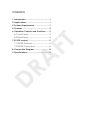
CONTENTS
1. Introduction ............................................ 1
2. Applications ........................................... 1
4. System Requirements ............................ 1
5. Features .................................................. 2
6. Operation Controls and Functions ....... 3
6.1 Front Panel ........................................3
6.2 Rear Panel.........................................4
FT
7. RS-232 control ........................................ 5
7.1 RS-232 Protocol .................................5
7.2 RS-232 Command ............................6
8. Connection Diagram ............................ 8
DR
A
........................................ 9
1. INTRODUCTION
The Audio Center is designed to allow multiple audio sources to be
controlled, switched and output to a variety of audio equipment. With
its 3 audio inputs and 2 audio outputs(including a 6.3mm headphone
output) you can integrate and convert USB/Line in audio source to
LPCM 2CH output synchronously to Line out and 6.3mm headphone.
2. APPLICATIONS
Multiple input/output Audio Center
PC/Mac USB audio input support
Home theater
FT
Show event audio set up
Educational/Lecture presentation
3. PACKAGE CONTENTS
#$
A
#%&'$*
#+"88"%9
#8"%';<
DR
Operational Manual
4. SYSTEM REQUIREMENTS
Input audio source equipment such as PC (USB), DVD player, MP3 and
=""
1
5. FEATURES
Supports Digital to Analog audio Conversion (DAC)
>?>@
#<GJ!
Synchronous output sound on both Line out and 6.3mm
headphone
Supports RS-232 controls
Elegant design and easy to install/using
Total Harmonic Distortion (THD): Less than 100dB (-20dBFs)
Volume contol of analog and headphone outputs
Direct power and mute button on unit
FT
Headphone output fades in after system is muted
DR
A
6.3mm headphone output (3.5mm mini-jack adaptor supplied)
2
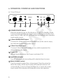
6. OPERATION CONTROLS AND FUNCTIONS
6.1 Front Panel
SOURCE
MUTE
HEADPHONE
1
2
LINE
4
5
3
USB
6
FT
POWER
POWER
1 POWER/SOURCE Select:
Press the wheel to turn on the device or to set it to standby mode.
Turn the wheel Left/Right to select input audio source (3.5mm Linelevel/ Line in/ USB), the LED will illuminate accordingly with selected
input audio source.
A
2 6.3mm HEADPHONE Output:
Connect to 6.3mm professional headphone set for user to enjoy
the individual professinal audio sound.
3 3.5mm Line-level input:
DR
Connect 3.5mm mini-jack cable to any audio equipment for
stereo input audio signal.
4 Power LED:
LED will illuminate when the Power is switched ON.
5 Input LED indicator:
The LED will illuminate according with selected input source.
6 Mute/Volume control:
Turn the wheel to adjust the volume levels. Press the wheel to
Mute the audio, all the input audio LED indicator will turn off
automatically. Turn the wheel Left/Right to un-mute the audio,
input audio LED indicator will illuminate to the last selection.
3
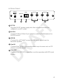
6.2 Rear Panel
DC 5V
LINE IN
USB
LINE OUT
SERVICE
L
R
1
2
3
4
L
R
5
1 DC 5V:
2 RS-232:
$8"%';><*$KQ
RS-232 control.
3 USB IN:
A
FT
Plug the 5V DC power supply into the unit and connect the
adaptor to an AC outlet.
Connect to a PC/MAC source for USB audio signal input or
"
4 Line IN:
DR
Connect the L/R IN to an analog stereo input source such as CD
player or media player.
5 Line OUT:
$XKYZ?Y$[
cables.
4
7. RS-232 CONTROL
7.1 RS-232 Protocol
DCT-24
Remote Control
PIN
Assignment
PIN
Assignment
1
NC
1
NC
2
2
Y
3
Y
3
4
NC
5
FT
NC
GND
5
GND
6
NC
6
NC
7
NC
7
NC
8
NC
8
NC
<
NC
<
A
4
NC
DR
@Y^#<G__
Data bit: 8-bits
Parity: None
Stop Bit: 1
5
7.2 RS-232 Command
Description
PORT 00
Switch Front In
PORT 01
Switch Line In
PORT 02
Switch USB In
VOL 00
Volume controller
VOL -(01---160)
Volume controller
POWER 00
Power off
POWER 01
Power on
MUTE 00
Mute off
MUTE 01
Mute on
FIX 00
LINE Out volume levels
FIX 01
XxQzZ
A
ME 03
FT
Command
HPR (00---05)
Reset to default
J*Y__^#+{
J*Y_#^8G{
DR
J*Y_G^+|{
J*Y_8^G__{
J*Y_|^8__{
J*Y_%^+__{
6
?
Display all available commands
z^
Support UART commands as list
commands : Description
PORT 00: Front In
PORT 01: Line In
PORT 02: USB In
POWER 00: POWER OFF
POWER 01: POWER ON
FT
MUTE 00: MUTE OFF
MUTE 01: MUTE ON
FIX 00: FIX OFF
FIX 01: FIX ON
HPR 00: 16_OHM
A
HPR 01: 32_OHM
HPR 02: 64_OHM
HPR 03: 200_OHM
HPR 04: 300_OHM
DR
HPR 05: 600_OHM
&ZX__^&ZX@
&ZX;~_#;;;#+_^&ZX;@
ME 03: Reset to default
INFO : Display the current status and F/W
version
? : Display all available commands
INFO
7
Display the current status and F/W version
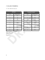
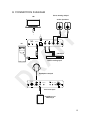
8. CONNECTION DIAGRAM
Stereo Analog Output
NB
Active Speakers
LINE IN
USB
LINE OUT
FT
DC 5V
SERVICE
PC
R
L
L
R
A
CD Player
DR
Stereo Analog Input
Headphone Output
SOURCE
POWER
POWER
MUTE
LINE
USB
HEADPHONE
Line-level Input
Smartphone or
MP3 Player
8
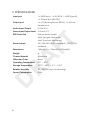
9. SPECIFICATIONS
Input port
#8"%X#YKXY$#?>@~@
#8"%<~Y>;G8G
Output port
#XKY~
>GY$#+"8
Headphone
Audio Input/Output
LPCM 2CH
Stereo Input/Output Level
2 Vrms ± 0.2
ESD Protection
Human body model:
±8 kV (air-gap discharge)
Power Supply
FT
±4 kV (contact discharge)
5V/ 2.6A DC (US/EU standards, CE/FCC/UL
Dimensions
#|%~##8~'8_~J
Weight
g
Aluminum
A
Chassis Material
Black
Operating Temperature
_$|_$
Storage Temperature
;G_$+_$K;|#|_
DR
Silkscreen Color
Relative Humidity
G_<_
YJ~;
Power Consumption
8.5W
9
10
FT
A
DR
ZZZF\SHXURSHFRP