1
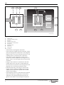
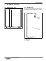
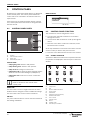
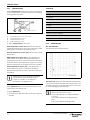
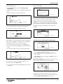
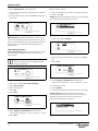
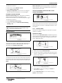
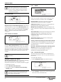
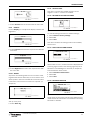
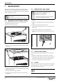
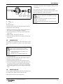
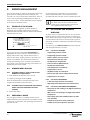
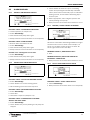
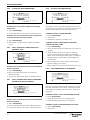
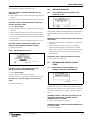
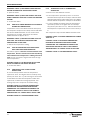
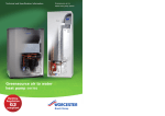
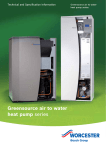
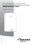
USER MANUAL
AIR TO WATER HEAT PUMP WITH DOMESTIC HOT WATER DISTRIBUTION UNIT
GREENSOURCE
6 KW, 7 KW AND 9.5 KW
6 720 641 467-00.1I
6 720 642 344 (2010/01)
UK/IE
TABLE OF CONTENTS
TABLE OF CONTENTS
1
Explanation of symbols and safety information 3
1.1
Explanation of symbols . . . . . . . . . . . . . . . 3
1.2
Safety precautions . . . . . . . . . . . . . . . . . . 3
2
The Benchmark scheme . . . . . . . . . . . . . . . . . . . 4
3
Use . . . . . . . . . . . . . . . . . . . . . . . . . . . . . . . . . . . 5
3.1
General information . . . . . . . . . . . . . . . . . 5
3.2
Heat pump function . . . . . . . . . . . . . . . . . 5
4
Standard delivery . . . . . . . . . . . . . . . . . . . . . . . . 7
4.1
Greensource 6-9.5 . . . . . . . . . . . . . . . . . . . 7
4.2
Internal unit . . . . . . . . . . . . . . . . . . . . . . . . 7
5
Control unit . . . . . . . . . . . . . . . . . . . . . . . . . . . . .
5.1
Additional heat gives more output . . . . . .
5.2
Hot water is given
priority over heating water . . . . . . . . . . . .
5.3
Automatic defrosting . . . . . . . . . . . . . . . . .
5.4
control unit function . . . . . . . . . . . . . . . . .
5.5
Heating control . . . . . . . . . . . . . . . . . . . . .
.8
8
8
8
6
Control panel . . . . . . . . . . . . . . . . . . . . . . . . . .
6.1
Control panel parts . . . . . . . . . . . . . . . . .
6.2
Control panel function . . . . . . . . . . . . . .
6.3
Settings . . . . . . . . . . . . . . . . . . . . . . . . . .
6.4
Menu . . . . . . . . . . . . . . . . . . . . . . . . . . . .
10
10
10
11
11
7
Maintenance . . . . . . . . . . . . . . . . . . . . . . . . . . .
7.1
Removing the external casing . . . . . . . . .
7.2
Remove dirt and leaves . . . . . . . . . . . . . .
7.3
Protective covers . . . . . . . . . . . . . . . . . .
7.4
Filter . . . . . . . . . . . . . . . . . . . . . . . . . . . .
7.5
Evaporator . . . . . . . . . . . . . . . . . . . . . . . .
7.6
Snow and ice . . . . . . . . . . . . . . . . . . . . . .
18
18
18
18
18
19
19
8
Error management . . . . . . . . . . . . . . . . . . . . . .
8.1
Example of an alarm: . . . . . . . . . . . . . . . .
8.2
Dimmed menu display . . . . . . . . . . . . . . .
8.3
Emergency mode . . . . . . . . . . . . . . . . . . .
8.4
All alarms and warning windows . . . . . . .
8.5
Alarm window . . . . . . . . . . . . . . . . . . . . .
8.6
Warning window . . . . . . . . . . . . . . . . . . .
8.7
Information from the heat pump . . . . . . .
20
20
20
20
20
21
23
23
9
Specification . . . . . . . . . . . . . . . . . . . . . . . . . . . 25
9.1
Factory settings . . . . . . . . . . . . . . . . . . . . 25
2
8
8
6 720 642 344 (2010/01)
EXPLANATION OF SYMBOLS AND SAFETY INFORMATION
1
EXPLANATION OF SYMBOLS AND SAFETY INFORMATION
1.1
EXPLANATION OF SYMBOLS
WARNING SYMBOLS
1.2
SAFETY PRECAUTIONS
GENERAL
Safety instructions in this document are
framed and identified by a warning triangle
which is printed on a grey background.
Electrical hazards are identified by a
lightning symbol surrounded by a warning
triangle.
Signal words indicate the seriousness of the hazard in
terms of the consequences of not following the safety
instructions.
• NOTICE indicates possible damage to property or
equipment, but where there is no risk of injury.
B Read the guide carefully and keep it to hand for future
use.
INSTALLATION AND COMMISSIONING
Installation and commissioning may only be carried out
by a qualified contractor.
RISK OF DAMAGE DUE TO OPERATOR ERROR
Operator errors can result in injury and damage to
property.
B Ensure that children never operate this appliance
unsupervised or play with it.
• CAUTION indicates possible injury.
B Ensure that only personnel who can operate this
appliance correctly have access to it.
• WARNING indicates possible severe injury.
SERVICE AND MAINTENANCE
• DANGER indicates possible risk to life.
B Only qualified personnel may carry out repairs.
Incorrect repairs can lead to serious risks to the user,
and a reduction in savings.
IMPORTANT INFORMATION
Notes contain important information in
cases where there is no risk of personal
injury or material losses and are identified
by the symbol shown on the left. They are
bordered by horizontal lines above and
below the text.
B Only use original spare parts.
B Service and maintenance must be carried out annually
by an authorised service representative.
ADDITIONAL SYMBOLS
Symbol
Meaning
B
a step in an action sequence
Æ
a reference to a related part in the document or to other related documents
•
a list entry
–
a list entry (second level)
Tab. 1
6 720 642 344 (2010/01)
3
THE BENCHMARK SCHEME
2
THE BENCHMARK SCHEME
Worcester, Bosch Group is a licensed member of the
Benchmark Scheme which aims to improve the
standards of installation and commissioning of domestic
heating and hot water systems in the UK and to
encourage regular servicing to optimise safety,
efficiency and performance.
Please ensure that the installer has fully completed the
Benchmark Checklist on the inside back pages of the
installation instructions supplied with the product and
that you have signed it to say that you have received a
full and clear explanation of its operation. The installer
is legally required to complete a commissioning
checklist as a means of complying with the appropriate
Building Regulations (England and Wales).
All installations must be notified to Local Area Building
Control either directly or through a Competent Persons
Scheme. A Building Regulations Compliance Certificate
will then be issued to the customer who should, on
receipt, write the Notification Number on the
Benchmark Checklist.
This product should be serviced regularly to optimise its
safety, efficiency and performance. The service engineer
should complete the relevant Service Record on the
Benchmark Checklist after each service.
The Benchmark Checklist may be required in the event
of any warranty work and as supporting documentation
relating to home improvements in the optional
documents section of the Home Information Pack.
4
6 720 642 344 (2010/01)
USE
3
USE
3.1
GENERAL INFORMATION
Worcester Greensource is a range of heat pumps that
draw energy from the outside air for heating purposes,
as well as for DHW heating if required. This product
range comprises the Greensource 6, Greensource 7 and
Greensource 9.5. Consequently, it covers the entire heat
demand.
A refrigerant circulates through the heat pump. In some
sections of the circuit it is in liquid form, in others it is
gaseous.
The Greensource 6-9.5 heat pumps can be linked to the
HWDU-151 internal unit. The internal unit contains a
DHW cylinder, thereby creating a complete system for
central heating and DHW. If required, the internal unit
acts as a additional heater. In such cases, the control
unit is fitted to the internal unit.
Once the heat pump has been installed and started,
there are a number of points that should be checked
regularly. This may concern an alarm triggering or
performing basic maintenance actions. In the first
instance the customer should try to rectify this and this
manual describes each step. If the problem is repeated,
you should contact the dealer.
These operating instructions describe the Greensource
heat pump, its components, maintenance, adjustments
etc. The operation of the internal unit is described in a
separate manual. Please read this document carefully,
even if you are operating the Greensource 6-9.5 together
with the HWDU-151.
3.2
HEAT PUMP FUNCTION
The heat pump draws energy from outside air. This
energy is transferred by heated water into the heating
system (radiators and/or underfloor heating system) of
the building and possibly for DHW heating. The internal
unit is equipped with a DHW cylinder.
Under certain conditions, e.g. when it is very cold
outside, the heat pump requires additional energy. This
is provided via an internal unit.
The heat pump comprises four main components:
• Evaporator
Transfers heat from the air to the refrigerant circuit
and simultaneously evaporates the refrigerant into a
gas.
• Compressor
Increases the refrigerant pressure.
• Condenser
Condenses the gas into a liquid and transfers heat
into the heating system.
• Expansion valve
Reduces the refrigerant pressure.
6 720 642 344 (2010/01)
5
USE
8
9
10
1
2
3
7
6
5
4
6 720 615 974-60.1I
Fig. 1
1
2
3
4
5
6
7
8
9
10
Greensource with HWDU-151 – function description
Internal unit
Underfloor heating system
Radiators
Heating circuit pump
Heat transfer medium pump
Heat pump
Expansion valve
Evaporator
Compressor
Condenser
• The fan blows air through the evaporator.
• The air meets the refrigerant in the evaporator. At this
point, the refrigerant is in liquid form. The refrigerant
begins to boil as soon as it meets the warmer air. The
resulting vapour is routed into the compressor.
• The pressure of the refrigerant increases in the
compressor and the temperature of the gas rises to
approx. +100 °C. The warm gas is then forced into the
condenser.
• Energy in the condenser is transferred to the heat
transfer fluid circuit. The gas is cooled down and
becomes fluid. The pressure in the refrigerant is still
high when it is routed to the expansion valve.
• Inside the heat pump, the energy is routed to the
heating system (underfloor heating system and/or
radiators) and via the DHW cylinder into the DHW
system of the building.
• The refrigerant pressure is reduced by the expansion
valve, from where the refrigerant is routed to the
evaporator. The refrigerant changes back into its
gaseous form whilst it runs through the evaporator.
6
6 720 642 344 (2010/01)
STANDARD DELIVERY
4
STANDARD DELIVERY
4.1
GREENSOURCE 6-9.5
4.2
INTERNAL UNIT
The control unit is integrated into the HWDU-151 when
the heat pump is combined with an internal unit, which
also incorporates a DHW cylinder. The heat pump is
installed externally; the internal unit internally.
1
6 720 616 818-11.1I
Fig. 2
2
Heat pump
6 720 614 050-02.1D
Fig. 3
1
2
6 720 642 344 (2010/01)
Internal unit
Control panel
DHW cylinder
7
CONTROL UNIT
5
CONTROL UNIT
The control unit regulates and monitors the central
heating and DHW. The monitoring function shuts down
the heat pump in case of operating faults. This prevents
damage to important heat pump components.
5.1
ADDITIONAL HEAT GIVES MORE
OUTPUT
Should the heat pump fail to deliver sufficient energy for
heating the building or if it was stopped because of
outside temperatures below approx. -20 °C, then the
heating operation needs to be boosted. For this, the
following option is available: Internal unit. If the heat
pump only covers part of the energy demand for heating,
the shortfall in heating output will be supplied by the
additional heater. The electric additional heater is
switched off when the heat pump can cover the
prevailing energy demand again.
5.2
HOT WATER IS GIVEN PRIORITY OVER
HEATING WATER
In a house with water based heating a difference is made
between heating water and hot water. The heating water
is for radiators and floor coils and hot water is for
showers and taps.
If the system is equipped with an internal unit, then the
DHW is heated inside the DHW cylinder in the internal
unit. A temperature sensor for monitoring the DHW
temperature is fitted. The heating water is routed
through the heating water jacket of the DHW cylinder
and thereby heats the internal cylinder. As soon as DHW
is called for, the control unit switches central heating off
and changes over to DHW priority.
5.3
AUTOMATIC DEFROSTING
Ice forms on the evaporator at outside temperatures
below +10°C. When ice forms to an extent that it
obstructs the air flow through the evaporator automatic
defrosting starts.
Defrosting is controlled by a four-way valve. The valve
reverses the flow of the refrigerant in the circuit so that
the hot gas from the compressor melts the ice on the
evaporator fins.
An additional function enables defrosting of the fan.
Warm air is drawn through the fan and thereby prevents
it from freezing up again.
5.4
CONTROL UNIT FUNCTION
During installation, the heat pump needs to be set to a
specific operating mode. The operating mode depends
on the respective operating conditions of the heat pump
as well as on its surroundings.
The installer must set up the heat pump in accordance
with the required operation and respective conditions.
5.4.1
HEAT PUMP WITH INTERNAL UNIT
The control unit adjusts its operating mode
automatically, if the heat pump is operated in
conjunction with an internal unit. Specifically, this
means that the heat pump operates with a additional
heater in the form of the internal unit and that DHW is
heated inside the DHW cylinder of the internal unit. A
temperature sensor fitted externally transmits the
outside temperature to the control unit. The control unit
regulates the generation of heat and DHW based on the
currently captured and selected values.
5.5
HEATING CONTROL
The control unit regulates heat generation for the
heating either exclusively via the outside temperature
sensor (weather-compensated control) or via a
combination of outside temperature sensor and room
temperature sensor (room temperature-dependent
control).
5.5.1
WEATHER-COMPENSATED CONTROL
As a standard, the heat pump control unit operates in
weather-compensated mode. The outside temperature
sensor is mounted on the coldest external wall of the
building which is least exposed to sunlight. The outside
temperature sensor signals the current outside
temperature to the control unit. Via the heat pump flow
temperature, the control unit automatically adapts the
internal room temperature of the building subject to the
prevailing outside temperature.
At the control unit, users can determine the flow
temperature in relation to the outside temperature by
modifying the heating curve setting. The heating curve
shows the heating water flow temperature in relation to
the outside temperature. Selecting a lower heating curve
results in a lower flow temperature and subsequently
higher energy savings.
The compressor stops for up to 60 s when
defrosting is activated or deactivated.
8
6 720 642 344 (2010/01)
CONTROL UNIT
5.5.2
WEATHER-COMPENSATED CONTROL WITH
ROOM TEMPERATURE DEPENDENCE
It is only the room where the room sensor is
located that can influence regulation of the
temperature.
Weather-compensated control with room temperature
dependence means that a temperature sensor
(accessory) is located in the lead room of the building.
The room temperature sensor is connected to the heat
pump and signals the current room temperature to the
control unit. The room temperature sensor influences
the heating curve flow temperature. The flow
temperature is reduced if the actual room temperature
is higher than the selected temperature.
A room temperature sensor is appropriate if, apart from
the outside temperature, other factors influence the
temperature inside the building, e.g. open fireplace, fan
heater, building subject to wind influence or direct
sunlight.
6 720 642 344 (2010/01)
9
CONTROL PANEL
6
CONTROL PANEL
All settings are made and possible alarms are displayed
via the control panel. The control panel enables the
control unit to be controlled in accordance with user
requirements.
MENU DISPLAY
If the heat pump is supplied together with an internal
unit, control panel and control unit are integrated into
the internal unit.
6.1
6 720 641 467-32.1I
Fig. 5
CONTROL PANEL PARTS
6.2
2
CONTROL PANEL FUNCTION
The menu dial is used to navigate the menus.
B Turn the menu dial anti-clockwise to scroll down
through the menus.
1
3
4
6 720 616 818-04.1I
Fig. 4
1
2
3
4
Internal unit control panel
Display
ON and fault indicator
Menu dial
Main ON/OFF switch
STATUS LAMP
B Turn the menu dial clockwise to scroll up through the
menus.
B Press the menu dial to confirm the selection, when
the desired row is marked.
At the top and bottom of each sub menu there are back
arrows to take you back to the previous menu.
B Press the menu dial when the back arrow is marked.
6.2.1
SYMBOL OVERVIEW
Symbols for different functions and components that are
in operation are displayed in the lower part of the menu
window.
• Lamp lights green: Switch in ON position.
• Lamp flashes green: Switch in OFF position.
• Lamp not lit: No voltage to control unit.
1
2
3
4
5
6
7
8
9
10
11
12
• Lamp flashes red: an alarm has been triggered and the
alarm has not been acknowledged (Æ Chapter 8).
• Lamp lights red: a fault has occurred. Contact the
installer.
The ON and fault indicator of the control
panel are located on the outside of the
control panel.
MENU DIAL
The menu dial is used to navigate between the menu
windows and to change the values of different settings.
The menu dial is also used to confirm selections.
SWITCH
The power switch button is used to start and switch off
the heating installation.
10
Fig. 6
1
2
3
4
5
6
7
8
9
10
11
12
Compressor
Fan
Electric additional heater
Power guard
DHW mode
DHW peak (pasteurisation)
Additional hot water
Time control
Heating mode
Alarm
Holiday mode
External input enabled
6 720 642 344 (2010/01)
6 720 616 817-24.1I
CONTROL PANEL
6.3
SETTINGS
The function menus are split into different levels to
cover various requirements.
HEATING SETUP WITH A ROOM TEMPERATURE
SENSOR INSTALLED:
• Menu Customer level, the most common functions.
• Advanced menu Customer level, other functions.
• Installer/Service Basic settings for installers or
service representatives.
Users of the heating installation only see what is
available in the two customer levels.
6.4
MENU
The initial menu in the control unit is called Menu. The
most frequent functions are included here. In Menu
shows the functions that your heating unit is set for. For
example it shows Extra hot water only if a water heater
is connected.
6 720 641 467-34.1I
Fig. 9
B Select Room temperature setting in the menu.
B Enter the desired room temperature. Min = +10°C,
max = +35°C.
B Select Save to save the change or Cancel to return
without saving.
Under Advanced you can also set how much you want
the room sensor to affect the heating system (Æ
Chapter 6.4.4).
After raising or lowering the temperature
setting wait at least a whole day before
making another temperature adjustment.
6 720 641 467-32.1I
Fig. 7
6.4.1
SET THE HEATING
Depending on whether the system is equipped with a
room temperature sensor or not, two options for setting
up the heating system are available.
6.4.2
EXTRA HOT WATER
If a DHW cylinder is installed, the DHW temperature can
be increased temporarily to approx. 65 °C with function
Extra hot water. In this case the heat pump is supported
in raising the temperature by the additional heater.
HEATING SETUP WITH NO ROOM TEMPERATURE
SENSOR INSTALLED:
6 720 641 467-35.1I
Fig. 10
B Select Extra hot water in the menu.
6 720 641 467-33.1I
Fig. 8
B Select the menu Temperature increase/decrease.
Select one of the options below:
B Set the number of hours that the function is to be
active by twisting the menu dial. Turn the knob
clockwise to increase and anticlockwise to reduce.
B Select Save to save the change or Cancel to return
without saving.
• ++ Much warmer(approx. +1 °C)
• + Warmer(approx. +0.5 °C)
• = No temperature change
• - Colder(approx. -0.5 °C)
• -- Much colder(approx. -1 °C)
B Press menu dial. Select Save to confirm your choice.
6 720 642 344 (2010/01)
11
CONTROL PANEL
6.4.3
TEMPERATURES
OVERVIEW
Under Temperatures displays the current temperatures
for the sensors which are most important for controlling
heating and the hot water.
Extended menu
Temperature
Hot water
Timers
1
2
Setting the clock
Display
Alarm
4
3
6 720 641 467-36.1I
Return to factory settings
Fig. 11
1
2
3
4
Access level
Room temperature sensor (accessory)
Outside temperature sensor
Flow temperature sensor
DHW temperature sensor
Deactivate alarm buzzer
Program version
Tab. 2
B Select Temperatures in the menu
6.4.5
TEMPERATURE
Flow temperature sensor (T1) indicates the heating
system flow temperature. This is the temperature of the
heating water routed into the heating system.
SET THE HEATING
This describes the heating settings.
Outside temperature sensor (T2) indicates the outside
temperature.
DHW temperature sensor (T3) is only displayed if a
DHW cylinder is installed. The display indicates the
temperature in the lower section of the outer cylinder of
the DHW cylinder. This temperature is approx. 5°C lower
than the temperature of the DHW in the inner cylinder.
H
Room temperature sensor (T5) is only displayed if a
room temperature sensor is installed. The display
indicates the temperature of the room where the sensor
is installed.
The display can also indicate the respective
V and H values. In the example shown V
is 20.0 °C, H is 45.6 °C. V and H are
described in (Æ chapter 6.4.5).
6.4.4
ADVANCED MENU
Under Advanced there are extra functions that can be
used to affect the heating unit.
To get to Advanced:
B Press the menu dial and hold it pressed for approx 5
seconds.
12
6 720 616 818-09.1I
Fig. 12
The heat curve determines the relationship between the
outdoor temperature and the flow line temperature. It is
possible to adjust the Left and Right values or the value
for every fifth degree between them.
In the delivered condition, the heating curve
slope V=20 and H=45.6 are set.
V=22, H=30: Underfloor heating embedded
in screed.
V=22, H=35: Underfloor heating between
joists.
V=20, H=55: Radiator heating system.
6 720 642 344 (2010/01)
CONTROL PANEL
To set the heat curve:
B Press menu dial.
B Select Heat curve in the menu Heating system
temperature.
B Select the value that is to be changed by twisting the
dial.
B Mark the value by pressing the dial once.
6 720 614 050-13.1D
Fig. 16
6 720 616 818-10.1I
Fig. 13
B Turn the menu dial to change the selected value.
The “Hysteresis” determines the point when the heat
pump compressor starts and stops relative to the
heating curve value. This value shifts relative to the
heating curve. This value shifts relative to the heating
curve to prevent a continuous cycling of the compressor.
Generally, the factory setting does not need to be
changed.
B Press the menu dial once and select save.
6 720 641 467-38.1I
6 720 641 467-37.1I
Fig. 17
Fig. 14
The heating curve can end up with a kink if a single value
of the curve is changed. This case occurs, for example, if
a temperature around 0 °C should be raised.
SETTING THE REQUIRED ROOM TEMPERATURE
B Turn the menu dial until the 0 °C is highlighted.
B Press the menu dial to highlight the flow temperature
value.
6 720 641 467-34.1I
B Turn the menu dial to set the required temperature.
Fig. 18
B Select Room temperature setting in the menu.
B Enter the desired room temperature. Min = +10°C,
max = +35°C.
6 720 616 818-14.1I
Fig. 15
B Press the menu dial to save the modified curve.
B Select Save to save the change or Cancel to return
without saving.
Room sensor influence means that the influence of the
sensor on the heating system can be adjusted.
Terminate menu point Heat curve:
B Turn the menu dial until the highlighted return arrow
is displayed.
6 720 641 467-39.1I
Fig. 19
To adjust the influence of the room sensor on the
heating system, increase or decrease the change factor.
B Select Room sensor influence in the menu.
6 720 642 344 (2010/01)
13
CONTROL PANEL
B Select Change factor in the sub-menu.
Remove a time control:
B Give the desired value by turning the menu dial. Min =
0, max = 10.
B Take out relevant time control according to the above.
B Press the dial in once and select Save by turning the
menu dial.
B Select mode Off.
Holiday allows the possibility of reducing (or increasing)
the temperature between two set dates.
6 720 641 467-40.1I
6 720 641 467-43.1I
Fig. 20
Fig. 23
Blocking time means that the influence of the room
sensor on the heating system is blocked for a set time
after a heat lowering period, to give the heat pump the
opportunity to raise the flow line temperature at a
slower speed.
B Select menu option Holiday.
TIME LIMITED SETTINGS
Time control heating enables you to increase or reduce
the temperature on different days of the week for
custom times.
Timer control is not recommended in
normal conditions as it can negatively affect
energy consumption.
6 720 641 467-44.1I
Fig. 24
B Select the start and end date in the format YY/MM/
DD.
B Select Save.
6 720 641 467-45.1I
6 720 641 467-41.1I
Fig. 21
B Select menu option Time control heating.
Fig. 25
B Select Change in temperature and select the
required value. Minimum = -20°C, maximum = +20°C.
B Select Day and time.
To cancel the function:
B Enter day and time.
B Select Holiday.
B Select On.
B Change the end date to the date before the start date.
B Select Save.
Remote control offers the option of reducing (or
increasing) the temperature by means of an external
(telephone) signal. This function requires that
appropriate equipment is installed.
6 720 641 467-42.1I
Fig. 22
B Select Change in temperature and select the
required value. Minimum = -20°C, maximum = +20°C.
B Select Save.
14
6 720 641 467-46.1I
Fig. 26
6 720 642 344 (2010/01)
CONTROL PANEL
To enable this function:
B Select Remote control On.
Direct start limit means that the delay is set aside and
heat production starts immediately if the temperature
drops below the set value.
B Change in temperature, set the amount of degrees
that the flow line temperature is to be changed.
HEATING, MAXIMUM OPERATING TIME AT HOT
WATER REQUIREMENT
B Select menu option Remote control.
EXTERNAL CONTROL HEATING
External control heating offers the option of shutting
down the heat generation independent of the
temperature by means of an external (telephone) signal.
To enable this function:
6 720 641 467-50.1I
B Select External control heating.
B Change the setting for External control blocking
heating to On.
Only activated selections are displayed. All
selections made are activated at the same
time by the external input.
HEATING SEASON
Fig. 30
This function ensures the hot water requirement during
heat production. The time is adjustable between 0 and
60 minutes.
6.4.6
DHW SETTINGS
The menus for DHW settings are only shown if a DHW
cylinder is installed.
EXTRA HOT WATER
6 720 641 467-47.1I
With menu point Extra hot water the DHW temperature
can be raised temporarily to approx. 65 °C. In this case
the heat pump is supported in raising the temperature
by the additional heater.
Fig. 27
The heat pump and the additional heater produce heat
only when the outdoor temperature falls below the
adjustable value Heating season limit.
6 720 641 467-35.1I
Fig. 31
B Select menu option Extra hot water.
6 720 641 467-48.1I
Fig. 28
B Turn the menu dial to set the duration of this function
in hours. Turning clockwise/anti-clockwise lengthens/
shortens the duration.
To avoid lots of starts and stops of the heat pump when
the outdoor temperature lies close to the limit value, the
activity of this function is delayed with the settable value
Delay.
6 720 641 467-51.1I
Fig. 32
B Set the required Stop temperature.
6 720 641 467-49.1I
B Select Save, to save your settings or Cancel to
discard your changes.
In menu Extra hot water you can check how long
Timers is still available.
Fig. 29
6 720 642 344 (2010/01)
15
CONTROL PANEL
Repeat the adjustment after the selected
time has expired to start a new period with
Extra hot water. Whilst the Extra hot water
function is operational the number of hours
can also be increased.
6.4.7
TIMERS
HOT WATER PEAK
6 720 641 467-01.1I
Fig. 35
There are a number of timers in the control unit. The
statuses for these are shown in the menu Timers.
6 720 641 467-52.1I
Fig. 33
Regular increase of the DHW temperature The interval
for pasteurisation is set in menu Hot water peak. If you
select 7 days, for example, then the DHW temperature is
raised to approx. 65 °C every seventh day. With Start
time you determine when pasteurisation should
commence.
TIME CONTROL HOT WATER
Extra hot water indicates the period for which the
required function Extra Hot Water is available.
Additional heat start indicates the remaining time for
delaying the start of the additional heater.
Mixing valve control delay indicates the delay for the
mixer control after expiry of the additional heater start
delay.
Alarm mode delay indicates the remaining time until the
additional heater starts following an alarm issue.
Compressor start indicates the time before the
compressor starts.
Delay before defrost indicates the remaining time
before a permissible defrost.
6 720 641 467-53.1I
Fig. 34
Function Time control hot water enables the complete
shutdown of DHW heating to save energy. This may be
appropriate during periods when high electricity tariffs
are applied. This will, however, result in a reduced DHW
provision. You enable this function like all other time
controls.
Time control hot water can impair the DHW
availability.
EXTERNAL CONTROL HOT WATER
External control hot water offers the option of shutting
down the DHW generation independent of the
temperature by means of an external (telephone) signal.
Heating, maximum operating time at hot water demand
indicates the time remaining before the maximum time
for heating mode is reached, if a simultaneous DHW
demand is active.
Hot water, maximum operating time at heating system
demand indicates the remaining time before the
maximum time for DHW heating is reached, if a
simultaneous heating demand is active.
6.4.8
SETTING THE CLOCK
The heat pump has functions that are dependent on
both the time and date. Thus it is important that these
are correct.
To set the date and time:
B Select Setting the clock in the advanced menu.
To enable this function:
B Select External control hot water.
B Change the setting for External control blocking
heating to On.
6 720 641 467-55.1I
Fig. 36
Only activated selections are displayed. All
selections made are activated at the same
time by the external input.
16
B Select Set date to adjust. This is done using the menu
dial in the order, Year-Month-Day.
6 720 642 344 (2010/01)
CONTROL PANEL
6.4.11 ACCESS LEVEL
This menu is used by the installer and the service
engineer. Level 0 = customer is standard.
6.4.12 RETURN TO FACTORY SETTINGS
6 720 641 467-56.1I
Fig. 37
B Select Set time and set the time with the menu dial.
6.4.9
DISPLAY
6 720 641 467-60.1I
In menu Display you can adjust the display contract and
brightness.
Fig. 41
To reset all settings and return to default settings:
B Select Return to factory settings.
B Select Yes.
B Select Save.
6 720 641 467-57.1I
Fig. 38
This does not affect the settings made in the Installer/
Service level.
6.4.13 DEACTIVATE ALARM BUZZER
B Select Contrast and select the required value with the
menu dial.
6 720 641 467-61.1I
Fig. 42
6 720 641 467-58.1I
Fig. 39
B Select Brightness and select the required value with
the menu dial.
When an alarm occurs, an alarm window is displayed and
a warning signal sounds. This warning signal is quiet if
the alarm is acknowledged or returned (Æ Chapter 8).
To deactivate the alarm buzzer:
B Select Deactivate alarm buzzer.
6.4.10 ALARM
Any alarms and warnings that have occurred are saved,
together with the time when they occurred. If there is an
alarm symbol in the menu window this means the alarm
is still active, and some form of action is required. (Æ
Chapter 8).
B Select Yes.
B Select Save.
6.4.14 PROGRAM VERSION
6 720 641 467-62.1I
6 720 641 467-59.1I
Fig. 43
The program version of the control unit is displayed. It is
useful to have this information on hand when contacting
the dealer or installer.
Fig. 40
Call up menu point:
B Select Alarm log.
6 720 642 344 (2010/01)
17
MAINTENANCE
7
MAINTENANCE
The heat pump requires a minimum of maintenance,
however, some servicing is still required to get optimal
performance from your heat pump. Check the following
items a few times per year:
7.2
WARNING: The thin aluminium fins are
sensitive and can be damaged easily
through incorrect handling.
B Never use hard objects.
DANGER: The heat pump is connected to
high current.
B Wear protective gloves during cleaning to
protect your hands from cuts.
B Break the power supply before rectifying.
7.1
REMOVING THE EXTERNAL CASING
REMOVE DIRT AND LEAVES
B Remove the r.h. external casing (looking from the
front).
Some maintenance areas are only accessible after
removal of the external casing.
B Open the cleaning aperture at the side of the heat
pump.
Remove the external casing:
B Remove dirt and leaves with a brush.
B Check that the drain hole is clear. If required, flush
with water.
B Remove dirt and leaves from the evaporator
compartment at the back of the heat pump (Æ Fig.
46).
6 720 616 818-16.1I
Fig. 44
B Undo the cover screws and remove the cover from the
heat pump.
6 720 616 818-18.1I
Fig. 46
7.3
PROTECTIVE COVERS
Over time dust and other dirt will collect on the heat
pump.
B Wipe the outside with a damp cloth if necessary.
B Scratches and damage to the outer plates should be
touched up using an anti corrosive rust-inhibitor.
B Use normal car polish to protect the paint.
7.4
6 720 616 818-17.1I
Fig. 45
B Undo the screws on the top of the heat pump turning
them a quarter turn.
FILTER
The filter prevents particles and dirt from entering the
heat pump interior. Over time, the filter can become
blocked and must be cleaned.
Fit the filter into the heat pump return.
B Pivot the external casing outward.
B Lift the external casing to release the sections from
the bottom.
18
6 720 642 344 (2010/01)
MAINTENANCE
B Remove snow and ice from the grille at the top of the
heat pump.
To prevent icing, the heat pump is equipped with
automatic defrosting. In the event of any problems, this
may need adjusting. Contact your dealer.
1
3
2
6 720 614 050-34.1D
Fig. 47
1
2
3
Filter
Locking ring
Plug
WARNING: During defrosting, ice can come
off the fan grille and can be blown off at high
speed.
B Avoid close proximity of the heat pump
during operation.
B Never look into the fan during defrosting.
Cleaning the filter:
B Switch off the heat pump with the ON/OFF switch.
B Remove the valve and plug.
B Remove the locking ring that retains the filer inside
the valve. For this use the pliers supplied.
B Remove the filter from the valve and flush the filter
with water.
B Refit the filter, locking ring and plug.
B Open the valve and start the heat pump via the ON/
OFF switch.
7.5
EVAPORATOR
If a coating (for example dust or dirt) has built up on the
surface of the evaporator (coil fins), it should be wiped
off.
WARNING: The thin aluminium fins are
fragile and can be damaged if careless.
Never wipe the delicate fins with a cloth.
B Use protective gloves to protect your
hands from cuts.
B Do not use a too powerful water jet.
Clean the evaporator:
B Switch off the heat pump with the ON/OFF switch.
B Remove casing (Æ chapter 7.1).
B Spray degreasing agent onto the evaporator fins.
B Wash off coating and cleaning agent with water. You
can clean the fins from the inside via the cleaning
aperture if the evaporator is severely contaminated.
Any cleaning agent you may use collects in the drain
hose.
7.6
SNOW AND ICE
In some regions and during time of heavy snowfall, snow
can settle on the grille on the back of the unit.
B Brush off snow from the casing holes.
6 720 642 344 (2010/01)
19
ERROR MANAGEMENT
8
ERROR MANAGEMENT
The control unit has an advanced monitoring system that
gives alarms if anything unforeseen happens. The
customer can correct most alarms themselves. There is
never a risk of affecting something when an alarm is
reset once or twice. Contact the dealer/service engineer
in the event of repeated alarms.
8.1
6 720 641 467-19.1I
Fig. 48
If you press the menu dial whilst Acknowledge is
highlighted, the alarm symbol is cancelled from the
display and the alarm log, and the alarm buzzer is
silenced. The alarm signal continues to be shown if a
fault is not remedied. The ON and fault indicators
change from flashing red to constant red indications.
Every alarm is stored in the fault log. Active alarms are
indicated by the alarm symbol.
8.2
DIMMED MENU DISPLAY
8.2.1
POSSIBLE CAUSE 1: FAULTY FUSE IN THE
DOMESTIC POWER SUPPLY.
B Check whether all domestic fuses are OK.
B If required, change/reset fuse/MCB.
After the fault has been remedied, the heat pump
restarts automatically 15 minutes later.
POSSIBLE CAUSE 2: AN MCB IN THE CONTROL
PANEL OR IN THE INTERNAL UNIT HAS
TRIPPED.
B Contact the dealer.
8.3
EMERGENCY MODE
The emergency function is available for the electric
additional heater in the internal unit. Information in this
connection is contained in the operating instructions of
the internal unit.
20
Emergency mode should not be mistaken
for alarm mode. In alarm mode the heat
pump stops. Heat generation continues to
be regulated by the control unit.
EXAMPLE OF AN ALARM:
When an alarm is triggered, an alarm window is
displayed and a warning signal sounds. The alarm
window displays the alarm causes and the time and date
that the alarm occurred.
8.2.2
In emergencies heat generation is covered by the
electric additional heater. This enables heat to be
provided until the customer service remedies the fault.
8.4
ALL ALARMS AND WARNING
WINDOWS
An alarm can occur temporarily due to various reasons.
However, there is never a risk involved in resetting an
alarm. All the alarms that can appear in the menu display
are described in this section. The descriptions give an
idea about the nature of the alarm and what can be done
to rectify it.
The alarm log (see Advanced menu) shows the alarms
and warnings that have occurred.
8.4.1
LIST OF ALL ALARMS:
• Tripped low pressure switch
• Tripped high pressure switch
• Failure / Short circuit on sensor.
• Faulty function in 4-way valve
• T6 High hot gas temperature
• Fault on electric additional heat
• T8 High flow temperature.
• Low temperature in condenser
• Tripped motor cut-out
• Air/Water pump not connected
• Fault in I/O card control cabinet/electric boiler
• Tripped motor cut-out fan
8.4.2
LIST OF ALL WARNINGS:
• Is the heat pump fused for this output?
• High temperature difference heat transfer fluid
8.4.3
LIST OF ALL INFORMATION WINDOWS
• Heat pump is now working at its highest permitted
temperature
• Add. heat is now working at its highest permitted
temperature
• This setting means that additional heat can take
over operation
• Temporary stop of hot water production
• Temporary stop of compressor operation
6 720 642 344 (2010/01)
ERROR MANAGEMENT
8.5
ALARM WINDOW
8.5.1
TRIPPED LOW PRESSURE SWITCH
B Check whether all valves are open. In a heating
system incorporating thermostatically controlled
valves, these valves must be fully open. In underfloor
heating systems, at least 50% of all heating loops
must be open.
B Where appropriate, select a higher speed for the
primary heating circuit pump.
B Notify customer service if the fault continues to occur.
6 720 641 467-18.1I
8.5.3
Fig. 49
FAILURE / SHORT CIRCUIT ON SENSOR
POSSIBLE CAUSE 1: EVAPORATOR BLOCKED.
B Clean evaporator (Æ chapter 7.5).
B Select Acknowledge.
B Wait until the heat pump starts again.
6 720 641 467-20.1I
B Notify customer service if the alarm occurs frequently.
POSSIBLE CAUSE 2: FAN BLOCKED.
B Remove debris that blocks the fan.
B Select Acknowledge.
B Wait until the heat pump starts again.
B Notify customer service if the alarm occurs frequently.
Possible cause 3: Refrigerant circuit fault.
B Select Acknowledge.
B Wait until the heat pump starts again.
B Notify customer service if the alarm occurs frequently.
8.5.2
TRIPPED HIGH PRESSURE SWITCH
Fig. 51
All sensors connected to the heating installation can give
an alarm in the event of a fault. In the example, it is
sensor T3, hot water, which has given an alarm. All
sensors give alarms in the same way.
PROBABLE CAUSE 1; TEMPORARY FAULT:
B Wait.
PROBABLE CAUSE 2; DEFECTIVE SENSOR OR
INCORRECT CONNECTION:
B Notify customer service if the fault continues to occur.
8.5.4
FAULTY FUNCTION IN 4-WAY VALVE
6 720 641 467-19.1I
6 720 641 467-21.1I
Fig. 50
Fig. 52
POSSIBLE CAUSE 1: AIR IN THE HEATING SYSTEM.
B Select Acknowledge.
B Check whether air is in the heating system.
B Fill the heating system and vent if required.
POSSIBLE CAUSE 1: 4-WAY VALVE FAULTY.
B Select Acknowledge.
B Notify customer service if the alarm occurs frequently.
POSSIBLE CAUSE 2; BLOCKED PARTICLE FILTER:
B Select Acknowledge.
B Check filter.
B Clean filter if required (Æchapter 7.4).
POSSIBLE CAUSE 3: INADEQUATE FLOW RATE
ACROSS THE HEAT PUMP.
B Select Acknowledge.
B Check whether the primary heating circuit pump has
stopped.
6 720 642 344 (2010/01)
21
ERROR MANAGEMENT
8.5.5
T6 HIGH HOT GAS TEMPERATURE
8.5.8
T8 HIGH FLOW TEMPERATURE
6 720 641 467-22.1I
6 720 641 467-24.1I
Fig. 53
Fig. 56
Possible cause 1: Excessive compressor operating
temperature.
Temperature sensor T8 is fitted inside the heat pump.
This stops the compressor for safety reasons as soon as
the flow temperature exceeds the selected value.
B Select Acknowledge.
B Contact the dealer in the event of repeated alarms.
POSSIBLE CAUSE 1: FILTER BLOCKED.
Possible cause 2: Occasionally excessive temperature
caused by unusual operating condition.
B Select Acknowledge.
B Clean filter if required (Æchapter 7.4).
B Select Acknowledge.
B Wait. Notify customer service if alarm repeatedly
occurs.
8.5.6
B Check filter.
FAULT ON ELECTRIC ADDITIONAL HEAT
(INTERNAL UNIT)
6 720 641 467-23.1I
POSSIBLE CAUSE 2: INADEQUATE FLOW RATE
ACROSS THE HEAT PUMP.
B Select Acknowledge.
B Check whether the primary heating circuit pump has
stopped.
B Check whether all valves are open. In a heating
system incorporating thermostatically controlled
valves, these valves must be fully open. In underfloor
heating systems, at least 50% of all heating loops
must be open.
B Where appropriate, select a higher speed for the
primary heating circuit pump.
Fig. 54
Possible cause 1: Overheat protection of the additional
heater has tripped.
B Notify customer service if the fault continues to occur.
8.5.9
LOW TEMPERATURE IN CONDENSER
B Select Acknowledge.
B Reset the overheat protection of the electric
additional heater.
B Contact the dealer in the event of repeated alarms.
8.5.7
FAULT ON ADDITIONAL HEAT FOR HEATING
SYSTEM (ELECTRIC/OIL BOILER)
6 720 641 467-25.1I
Fig. 57
The alarm is triggered because the temperature inside
the heat pump is too low. Initially, a warning is issued.
Following four warnings within two hours, an alarm is
triggered.
6 720 641 467-69.1I
POSSIBLE CAUSE 1: AIR IN THE HEATING SYSTEM.
Fig. 55
B Select Acknowledge.
Possible cause 1: Overheat protection of the additional
heater has tripped.
B Check whether air is in the heating system.
B Select Acknowledge.
POSSIBLE CAUSE 2; BLOCKED PARTICLE FILTER:
B Reset overheat protection of the additional heater.
B Select Acknowledge.
B Contact the dealer in the event of repeated alarms.
B Check filter.
22
B Fill the heating system and vent if required.
6 720 642 344 (2010/01)
ERROR MANAGEMENT
B Clean filter if required (Æchapter 7.4).
8.6
WARNING WINDOW
POSSIBLE CAUSE 3: PRIMARY HEATING CIRCUIT
PUMP FAULT.
8.6.1
HIGH TEMPERATURE DIFFERENCE HEAT
TRANSFER FLUID
B Check whether the primary heating circuit pump has
stopped.
B Notify customer service if the fault continues to occur.
POSSIBLE CAUSE 4: INADEQUATE/NO FLOW RATE
ACROSS THE HEAT PUMP.
6 720 641 467-28.1I
B Select Acknowledge.
B Check whether the primary heating circuit pump has
stopped.
B Check that all the valves are open. The thermostat
valves in heating systems should be fully open and in
floor heating systems at least half of the coils should
be fully open.
B Notify customer service if the fault continues to occur.
POSSIBLE CAUSE 5: INADEQUATE AMOUNT OF
WATER IN THE DOMESTIC HEATING SYSTEM.
B Contact the dealer.
8.5.10 TRIPPED MOTOR CUT-OUT
Fig. 59
This warning window is displayed when the temperature
difference between sensors T8 and T9 becomes too
high.
PROBABLE CAUSE 1; INSUFFICIENT FLOW OVER THE
HEAT PUMP:
B Check whether the primary heating circuit pump has
stopped.
B Check whether all valves are open. In a heating
system incorporating thermostatically controlled
valves, these valves must be fully open. In underfloor
heating systems, at least 50% of all heating loops
must be open.
POSSIBLE CAUSE 2; BLOCKED PARTICLE FILTER:
B Clean filter (Æ chapter 7.4).
6 720 641 467-26.1I
8.7
INFORMATION FROM THE HEAT
PUMP
8.7.1
HEAT PUMP IS NOW WORKING AT ITS
HIGHEST PERMITTED TEMPERATURE
Fig. 58
POSSIBLE CAUSE 1: OCCASIONAL FAULT OR
ELECTRICITY NETWORK OVERLOADED.
B Select Acknowledge.
B Wait until the heat pump starts again.
B Notify customer service if the fault continues to occur.
Possible cause 2: Power supply to the heat pump
failed.
B Contact the dealer.
6 720 641 467-29.1I
Fig. 60
Temperature sensor T9 is fitted inside the heat pump.
This stops the compressor for safety reasons as soon as
the return temperature is too high. The limit is approx.
59 °C.
PROBABLE CAUSE 1; THE HEAT SETTING IS SET SO
HIGH THAT THE HEATING SYSTEM’S RETURN
TEMPERATURE IS TOO HIGH:
B Reduce the temperature setting.
PROBABLE CAUSE 2; THE HOT WATER TEMPERATURE
IS SET TOO HIGH:
B Contact the dealer.
6 720 642 344 (2010/01)
23
ERROR MANAGEMENT
PROBABLE CAUSE 3; THE UNDER FLOOR HEATING
SYSTEM OR RADIATOR VALVES ARE CLOSED:
8.7.5
B Open the valves.
Could occur for two different reasons:
PROBABLE CAUSE 4; THE FLOW ACROSS THE HEAT
PUMP IS GREATER THAN THE FLOW IN THE HEATING
SYSTEM:
1. If the temperature captured by sensor T2 is lower
than the lowest temperature envelope. Switches back
when the temperature captured by sensor T2 is higher
than the lowest temperature envelope for 30 minutes.
B Contact the dealer.
8.7.2
ADD. HEAT IS NOW WORKING AT ITS HIGHEST
PERMITTED TEMPERATURE
Temperature sensor T9 is fitted inside the heat pump.
This stops the compressor for safety reasons and limits
the electric additional heater as soon as the return
temperature is too high. The limit for the electric
additional heater is approx. 58 °C.
PROBABLE CAUSE 1; THE HEAT SETTING IS SET SO
HIGH THAT THE HEATING SYSTEM’S RETURN
TEMPERATURE IS TOO HIGH:
B Reduce the temperature setting.
8.7.3
THIS SETTING MEANS THAT ADDITIONAL
HEAT CAN TAKE OVER OPERATION
Information appears if Electric cassette limitation start
temperature, Electric cassette forced shut off, Mixing
valve limitation start temperature or Mixing valve force
close are set more than 1 degree lower than T9 high
return temperature.
TEMPORARY STOP OF COMPRESSOR
OPERATION
2. In case of heating operation and if the temperature
captured by sensor T6 is higher than for envelope
stop (factory-set value: 117 °C). Switches back when
the temperature captured by sensor T2 has risen by 2
K.
The compressor stops and the additional heater starts.
POSSIBLE CAUSE 1: OUTSIDE TEMPERATURE LOWER
THAN -20 °C.
POSSIBLE CAUSE 2: EXCESSIVE TEMPERATURE
DIFFERENTIAL BETWEEN EVAPORATION AND
CONDENSING. THE COMPRESSOR PERMITS THE
ADDITIONAL HEATER TO SUPPLY THE CORRECT
TEMPERATURE IF IT CANNOT DO SO ON ITS OWN.
POSSIBLE CAUSE 3: LOW REFRIGERANT LEVEL.
POSSIBLE CAUSE 1: THE INSTALLER SETS A HIGH
VALUE FOR ONE OF THE ABOVE SETTINGS.
B Contact the dealer.
8.7.4
TEMPORARY STOP OF HOT WATER
PRODUCTION
In case of DHW operation and if the temperature
captured ar senor T6 is higher than for envelope stop
(factory-set value: 117 °C), this message is issued until
T3 has fallen 5 K below the temperature which was
captured by T3 when the message appeared. This
message stops the compressor for DHW heating.
POSSIBLE CAUSE 1: EXCESSIVE TEMPERATURE
DIFFERENTIAL BETWEEN EVAPORATION AND
CONDENSING. THE COMPRESSOR PERMITS THE
ADDITIONAL HEATER TO SUPPLY THE CORRECT
TEMPERATURE IF IT CANNOT DO SO ON ITS OWN.
POSSIBLE CAUSE 2: LOW REFRIGERANT LEVEL.
24
6 720 642 344 (2010/01)
SPECIFICATION
9
SPECIFICATION
9.1
FACTORY SETTINGS
Advanced menu
The table displays the factory values (F value) of the
settings that you, as a customer, (K) can change via the
customer menus Menu and Advanced menu.
Read the table as follows: To find the settings for
Holiday go to Advanced menu, select Temperature then
select Time limited settings and then Holiday.
Menu
Level
F-value
K
= (unchanged)
Room temperature setting(T5)
K
20°C
Extra hot water
K
0h
Temperature increase/decrease
(not T5)
Tab. 3
Advanced menu
Level
F-value
Temperature
Heating system temperature
_”_\Heat curve
K
V=20.0°C / H=45.6°C
_”_\Hysteresis
_”_\_”_\Maximum
K
16°C
_”_\_”_\Minimum
K
4°C
_”_\_”_\Time factor
K
10
Room sensor settings (T5)
_”_\Room temperature setting
K
20°C
_”_\_”_\Change factor
K
5
_”_\_”_\Blocking time
K
4h
_”_\Time control heating
K
Off
_”_\_”_\Day and time
K
_”_\_”_\Change in temperature
K
-10°C
_”_\Holiday
K
Off
_”_\_”_\Date
K
_”_\_”_\Change in temperature
K
_”_\Remote control
K
_”_\_”_\Remote control
K
Off
_”_\_”_\Change in temperature
K
0 °C
External control heating
K
Off
_”_\Heating season limit
K
18°C
_”_\Delay
K
4h
_”_\Room sensor influence
Time limited settings
Level
F-value
_”_\Direct start limit
K
10°C
Heating, maximum operating
K
20 min.
_”_\Number of hours
K
0
_”_\Stop temperature
K
65°C
_”_\Interval
K
0 days
_”_\Start time
K
03:00
Time control hot water
K
Off
External control hot water
K
Off
time at hot water demand
Hot water (T3)
Extra hot water
Hot water peak
Setting the clock
Set date
K
Set time
K
Display
Contrast
K
5
Brightness
K
10
_”_\Delete alarm log?
K
No
Access level
K
0
Return to factory settings
K
No
Deactivate alarm buzzer
K
No
Program version
K
xx.xxx
Alarm
Alarm log
Tab. 4
-10 °C
Heating season
Tab. 4
6 720 642 344 (2010/01)
25
SPECIFICATION
26
6 720 642 344 (2010/01)
SPECIFICATION
6 720 642 344 (2010/01)
27
WORCESTER, BOSCH GROUP:
TECHNICAL:
08705 266241
SERVICE:
08457 256206
SPARES:
01905 752571
LITERATURE:
0844 892 9800
TRAINING:
01905 752526
SALES:
01905 752640
WEBSITE:
Worcester, Bosch Group
Cotswold Way, Warndon, Worcester WR4 9SW.
Tel. 0844 892 9900
Worcester, Bosch Group is a brand name of Bosch Thermotechnology Ltd.
worcester-bosch.co.uk
6 720 642 344
worcester-bosch.co.uk