1
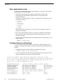
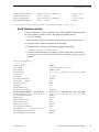
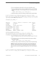
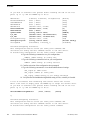
Fibre Channel Switch
Installation Manual
071-8429-01
JANUARY 2007
Copyright
Copyright © 2006 Grass Valley, Inc. All rights reserved. Printed in the United States of America.
Portions of software © 2000 – 2006, Microsoft Corporation. All rights reserved.
This document may not be copied in whole or in part, or otherwise reproduced except as
specifically permitted under U.S. copyright law, without the prior written consent of Grass
Valley, Inc., P.O. Box 59900, Nevada City, California 95959-7900
This product may be covered by one or more U.S. and foreign patents.
Trademarks
Grass Valley, K2, Aurora, Turbo, M-Series, Profile, Profile XP, NewsBrowse, NewsEdit,
NewsQ, NewsShare, NewsQ Pro, Aurora, and Media Manager are either registered
trademarks or trademarks of Grass Valley, Inc. in the United States and/or other countries.
Other trademarks used in this document are either registered trademarks or trademarks of the
manufacturers or vendors of the associated products. Grass Valley, Inc. products are covered
by U.S. and foreign patents, issued and pending. Additional information regarding Grass
Valley, Inc. trademarks and other proprietary rights may be found at
www.thomsongrassvalley.com.
Disclaimer
Product options and specifications subject to change without notice. The information in this
manual is furnished for informational use only, is subject to change without notice, and should
not be construed as a commitment by Grass Valley, Inc. Grass Valley, Inc. assumes no
responsibility or liability for any errors or inaccuracies that may appear in this publication.
U.S. Government
Restricted Rights
Legend
Use, duplication, or disclosure by the United States Government is subject to restrictions as set
forth in subparagraph (c)(1)(ii) of the Rights in Technical Data and Computer Software clause
at DFARS 252.277-7013 or in subparagraph c(1) and (2) of the Commercial Computer
Software Restricted Rights clause at FAR 52.227-19, as applicable. Manufacturer is Grass
Valley, Inc., P.O. Box 59900, Nevada City, California 95959-7900 U.S.A.
Revision Status
2
Rev Date
Description
January 29, 2007
Updated release for QLogic SANbox 5202, 071-8429-01
Fibre Channel Switch Installation Manual
29 January 2007
Contents
Preface .................................................................................................................. 5
Grass Valley Product Support ................................................................................. 5
Welcome ............................................................................................................... 7
Support for your Fibre Channel switch .................................................................... 7
Profile System Software Requirements................................................................... 7
Configuring your Fibre Channel switch ................................................................... 7
Enter administrator mode ................................................................................... 8
Configure Ethernet LAN settings ........................................................................ 8
Verify firmware version ....................................................................................... 9
Port and switch configuration ............................................................................. 10
Combining with the QLogic SANbox2 switch .......................................................... 13
Connecting devices to the switch ............................................................................ 13
Cable lengths...................................................................................................... 13
Fabric topology ................................................................................................... 13
Compatible Fibre Channel Devices .................................................................... 13
Monitoring your switch with NetCentral ................................................................... 14
Maintenance procedures......................................................................................... 14
Resetting the switch to factory defaults .............................................................. 14
Resetting the switch manually ............................................................................ 15
29 January 2007
Fibre Channel Switch Installation Manual
3
Contents
4
Fibre Channel Switch Installation Manual
29 January 2007
Preface
Grass Valley Product Support
To get technical assistance, check on the status of a question, or to report new issue, contact
Grass Valley Product Support via e-mail, the Web, or by phone or fax. Contact Grass Valley
first regarding problems with third party software on Grass Valley products, such as the
Microsoft® Windows® operating system, Windows Media® player, Internet Explorer®
internet browser, and SQL Server™.
Web Technical Support
To access support information on the Web, visit the product support Web page on the
Grass Valley Web site. You can download software or find solutions to problems by
searching our Frequently Asked Questions (FAQ) database.
World Wide Web: http://www.thomsongrassvalley.com/support/
Technical Support E-mail Address: [email protected].
Phone Support
Use the following information to contact product support by phone during business
hours. Afterhours phone support is available for warranty and contract customers.
International
(France)
+800 80 80 20 20
+33 1 48 25 20 20
Italy
+39 02 24 13 16 01
+39 06 87 20 35 42
International
(United States,
Canada)
+1 800 547 8949
+1 530 478 4148
Belarus, Russia,
Tadzikistan,
Ukraine,
Uzbekistan
+7 095 258 09 20
+33 (0) 2 334 90 30
Hong Kong,
Taiwan, Korea,
Macau
+852 2531 3058
Indian
Subcontinent
+91 11 515 282 502
+91 11 515 282 504
Australia, New
Zealand
+61 1300 721 495
Germany, Austria,
Eastern Europe
+49 6150 104 444
Central, South
America
+55 11 5509 3440
Near East, Africa
+33 1 48 25 20 20
China
+861 066 0159 450
Netherlands
+31 (0) 35 62 38 421
Belgium
+32 (0) 2 334 90 30
Northern Europe
+45 45 96 88 70
Japan
+81 3 5484 6868
Singapore
+65 6379 1313
Malaysia
+603 7805 3884
Spain
+41 487 80 02
Middle East
+971 4 299 64 40
UK, Ireland, Israel
+44 118 923 0499
Authorized Support Representative
A local authorized support representative may be available in your country. To locate the
support representative for your country, visit the product support Web page on the Grass
Valley Web site.
29 January 2007
Fibre Channel Switch Installation Manual
5
Preface
6
Fibre Channel Switch Installation Manual
29 January 2007
Welcome
You can use your 8, 16, or 20 port QLogic 5202 SANbox Fibre Channel switch to
create SCSI protocol fabrics for Grass Valley products. The QLogic 5202 SANbox
Fibre Channel switch does not support Internet Protocol (IP) fabrics.
The 8 and 16 port switches have 2Gb/1Gb auto-detecting ports. The 20 port switch
includes four 10 Gb ports, which are for Inter-Switch Links (ISLs).
This manual supplements the information provided by the QLogic 5202 SANbox
Switch manuals that you received with your switch. Please refer to the following
QLogic manuals when installing and configuring your QLogic 5202 SANbox Switch.
• SANbox 5200 Series Fibre Channel Switch Installation Guide - This is your
primary reference on the installation and initial setup of your specific model of
QLogic switch. It also provides maintenance and repair information.
• SANbox 5200 Series Switch Management User’s Guide - This manual describes the
switch management software application that allows you to monitor and administer
your QLogic 5202 SANbox Switch.
You can find these manuals on the CD that you receive with the Fibre Channel switch.
Support for your Fibre Channel switch
Your QLogic 5202 SANbox Switch is sold, supported, and serviced by Grass Valley.
If you have any questions about your QLogic 5202 SANbox Switch, or if you need
any help or service for the switch, please contact your local Grass Valley Support
representative listed at the front of this manual
NOTE: Do not contact QLogic directly for support of your QLogic 5202 SANbox
Switch.
Profile System Software Requirements
Profile System Software version 5.2 or higher is required for operation with a QLogic
5202 SANbox Switch. Earlier versions do not support this Fibre Channel switch.
Refer to the Profile Release Notes for instructions on how to install your Profile
System Software, as well as information on the new features that are included in the
release.
Configuring your Fibre Channel switch
Your QLogic 5202 SANbox Switch must be configured so that you can control and
monitor it in your LAN environment. As you make these settings, you should also
verify that all the other switch and port settings are appropriate for operation in a
Grass Valley SCSI protocol Fibre Channel fabric. The following instructions describe
how to verify and assign these settings using a serial port connection. The same
commands can also be used in a Telnet session over the Ethernet port.
NOTE: You can use the SANsurfer Management software application described in
the SANbox 5200 Series Switch Management User’s Guide to establish Ethernet LAN,
SNMP, and basic switch and port settings.
29 January 2007
Fibre Channel Switch Installation Manual
7
Welcome
Enter administrator mode
You must be in administrator mode to make changes to your QLogic 5202 SANbox
Switch settings. To enter this mode:
1. Establish serial connection to the QLogic 5202 SANbox Switch using a
null-modem cable and Windows HyperTerminal or an equivalent serial
communication tool.
To log on to a switch through the serial port, configure the workstation port with
the following settings:
• 9600 baud
• 8-bit character
• 1 stop bit
• No parity
Refer to the SANbox 5200 Series Fibre Channel Switch Installation Guide for
connection information.
2. In the serial communication window, press Enter to establish communications,
then log in to the switch with username admin and password password, all in
lowercase characters.
3. Type the following command to enter the administrator mode, which allows you to
modify settings.
SANbox #> admin start
Configure Ethernet LAN settings
You must assign an Ethernet IP address, a subnet mask, and a default gateway to
configure your QLogic 5202 SANbox Switch for operation in your Ethernet local area
network.
1. In administrator mode, type the following command at the prompt:
SANbox (admin) #> set setup system
2. As you step through each of the following configuration items, assign your local
settings as needed, or press Enter to accept the defaults.
A list of attributes with formatting and current values will follow.
Enter a new value or simply press the ENTER key to accept the current value.
If you wish to terminate this process before reaching the end of the list
press 'q' or 'Q' and the ENTER key to do so.
Eth0NetworkDiscovery
Eth0NetworkAddress
Eth0NetworkMask
Eth0GatewayAddress
AdminTimeout
InactivityTimeout
LocalLogEnabled
RemoteLogEnabled
8
(1=Static, 2=Bootp, 3=Dhcp, 4=Rarp)
(dot-notated IP Address)
(dot-notated IP Address)
(dot-notated IP Address)
(dec value 0-1440 minutes, 0=never)
(dec value 0-1440 minutes, 0=never)
(True / False)
(True / False)
Fibre Channel Switch Installation Manual
[Static]
[10.16.42.117]
[255.255.254.0]
[10.16.42.1]
[30]
[0]
[True]
[False]
29 January 2007
Verify firmware version
RemoteLogHostAddress
NTPClientEnabled
NTPServerAddress
EmbeddedGUIEnabled
(dot-notated IP Address)
(True / False)
(dot-notated IP Address)
(True / False)
[10.0.0.254]
[False
[10.0.0.254]
[True]
Do you want to save and activate this system setup? (y/n): [n] y
Verify firmware version
You can use the show switch command to view switch information and confirm that
the active firmware version is correct. The minimum qualified image is:
• 5.0.0.17.0 or higher
Contact your Grass Valley representative to determine the current required version.
To view the current version information, do the following:
1. In administrator mode type the following command at the prompt:
SANbox (admin) #> show switch
2. View the switch information, an example of which is shown here. Note that the
ActiveImageVersion - build date specifies the active firmware image version and
build date.
Switch Information
-----------------SymbolicName
SwitchWWN
SwitchType
BootVersion
CreditPool
DomainID
FirstPortAddress
FlashSize - MBytes
LogFilterLevel
MaxPorts
NumberOfResets
ReasonForLastReset
ActiveImageVersion - build date
PendingImageVersion - build date
ActiveConfiguration
AdminState
AdminModeActive
BeaconOnStatus
OperationalState
PrincipalSwitchRole
BoardTemp (1) - Degrees Celsius
SwitchDiagnosticsStatus
SwitchTemperatureStatus
29 January 2007
SANbox
10:00:00:c0:dd:07:13:79
SANbox 5202
V1.2.0.16.0 (Mon Sep 13 15:35:12 2004)
0
2 (0x2)
020000
128
Info
20
6
PowerUp
V5.0.0.17.0 (Thu Mar 10 16:11:44 2005)
V5.0.0.17.0 (Thu Mar 10 16:11:44 2005)
SANbox
Online
True
False
Online
False
23
Passed
Normal
Fibre Channel Switch Installation Manual
9
Welcome
3. If the correct firmware version is not loaded, refer to the SANbox 5200 Series Fibre
Channel Switch Installation Guide for information on how to install firmware.
Port and switch configuration
You must ensure that all the Fibre Channel ports are correctly configured for
operation with Grass Valley equipment. With these settings, you can use any port in
a SCSI fabric without any further configuration.
1. In administrator mode, type the following command at the prompt to enter the
configuration mode:
SANbox (admin) #> config edit
2. In configuration mode, type the following command at the prompt to view the
configuration of 2 Gb ports on the switch:
SANbox (admin-config) #> set config ports
3. Modify the settings as needed. The following example shows the required settings.
A list of attributes with formatting and current values for the port
number or port type specified at the command line will follow.
Each value that is changed will be set for all ports, except ports 16-19.
Ports 16-19 must be modified with the 'set config port PORT_NO' command.
Each value that is changed will be set for ALL PORTS.
If you wish to terminate this process before reaching the end of the
list press 'q' or 'Q' and the ENTER key to do so.
Configuring ALL ports (displaying values from port number: 0)
---------------------------------------------------------AdminState
LinkSpeed
PortType
ALFairness
DeviceScanEnable
ForceOfflineRSCN
ARB_FF
InteropCredit
ExtCredit
FANEnable
AutoPerfTuning
MSEnable
NoClose
IOStreamGuard
PDISCPingEnable
(1=Online, 2=Offline, 3=Diagnostics, 4=Down)
(1=1Gb/s, 2=2Gb/s, A=Auto)
(GL / G / F / FL / Donor)
(True / False)
(True / False)
(True / False)
(True / False)
(decimal value, 0-255)
(dec value, increments of 15, non-loop only)
(True / False)
(True / False)
(True / False)
(True / False)
(Enable / Disable / Auto)
(True / False)
[Online]
[Auto]
[GL]
[False]
[True]
[False]
[False]
[0]
[0]
[True]
[True]
[True]
[False]
[Disabled]
[True]
Finished configuring attributes.
This configuration must be saved (see config save command) and
activated (see config activate command) before it can take effect.
To discard this configuration use the config cancel command.
10
Fibre Channel Switch Installation Manual
29 January 2007
Port and switch configuration
4. If you are configuring a switch with 16 or fewer ports, skip ahead to step 8.
5. If you are configuring a 20 port switch, in configuration mode, type the following
command at the prompt to view the configuration of port 16 (a 10 Gb port) on the
switch.
SANbox (admin-config) #> set config port 16
6. Modify the settings as needed. The following example shows the required settings.
A list of attributes with formatting and current values will follow.
Enter a new value or simply press the ENTER key to accept the current value.
If you wish to terminate this process before reaching the end of the list press
'q' or 'Q' and the ENTER key to do so.
Configuring Port Number: 16
-----------------------AdminState
LinkSpeed
PortType
SymPortName
DeviceScanEnable
ForceOfflineRSCN
AutoPerfTuning
MSEnable
IOStreamGuard
(1=Online, 2=Offline, 3=Diagnostics, 4=Down) [Online]
(10=10Gb/s)
[10Gb/s]
(G / F)
[G]
(string, max=32 chars)
[10G-16]
(True / False)
[True]
(True / False)
[False]
(True / False)
[True]
(True / False)
[True]
(Enable / Disable / Auto)
[Disabled]
Finished configuring attributes.
This configuration must be saved (see config save command) and
activated (see config activate command) before it can take effect.
To discard this configuration use the config cancel command.
7. If you are configuring a 20 port switch, repeat step 4 and step 6 for port 17, 18, and
19.
8. In configuration mode, type the following command at the prompt to configure
global switch settings:
SANbox (admin-config) #> set config switch
9. Modify the settings as needed. The following example shows the required settings.
NOTE: Each QLogic 5202 SANbox Switch must have a unique DomainID for the
local fabric. You should specify these values individually for each switch and not
allow the switches to select their own DomainID values. Setting DomainIDLock to
True prevents the switch from changing the DomainID when a new switch is added to
fabric.
A list of attributes with formatting and current values will follow.
Enter a new value or simply press the ENTER key to accept the current value.
29 January 2007
Fibre Channel Switch Installation Manual
11
Welcome
If you wish to terminate this process before reaching the end of the list
press 'q' or 'Q' and the ENTER key to do so.
AdminState
BroadcastEnabled
InbandEnabled
FdmiEnabled
FdmiEntries
DefaultDomainID
DomainIDLock
SymbolicName
R_A_TOV
E_D_TOV
PrincipalPriority
ConfigDescription
InteropMode
(1=Online, 2=Offline, 3=Diagnostics)
(True / False)
(True / False)
(True / False)
(decimal value, 0-1000)
(decimal value, 1-239)
(True / False)
(string, max=32 chars)
(decimal value, 100-100000 msec)
(decimal value, 10-20000 msec)
(decimal value, 1-255)
(string, max=64 chars)
(0=Standard, 1=Interop_1)
[Online]
[True]
[True]
[True]
[1000]
[2]
[True]
[SANbox]
[2000]
[1000]
[254]
[FC-SCSI Config]
[Standard]
Finished configuring attributes.
This configuration must be saved (see config save command) and
activated (see config activate command) before it can take effect.
To discard this configuration use the config cancel command.
10.Type the following command to save your configuration:
SANbox (admin-config) #> config save
11.Type the following command to activate your configuration:
SANbox (admin-config) #> config activate
12. Confirm activation of the configuration when prompted.
13.Type the following commands to view the threshold advanced settings:
sb2_16port #> admin start
sb2_16port (admin) #> config edit
sb2_16port (admin-config) #> set config threshold
14. Verify that the ThesholdMonitoringEnabled setting is False, or modify it if needed.
A list of attributes with formatting and current values will follow.
Enter a new value or simply press the ENTER key to accept the current value.
If you wish to terminate this process before reaching the end of the list
press 'q' or 'Q' and the ENTER key to do so.
ThresholdMonitoringEnabled
(True / False)
[False]
q
Finished configuring attributes.
This configuration must be saved (see config save command) and
activated (see config activate command) before it can take effect.
To discard this configuration use the config cancel command.
12
Fibre Channel Switch Installation Manual
29 January 2007
Combining with the QLogic SANbox2 switch
15. Save and activate the configuration with the following commands:
sb2_16port (admin-config) #> config save
sb2_16port (admin) #> config activate
16. Confirm activation of the configuration when prompted.
You must make various SNMP settings so that you can monitor your switch with
NetCentral. Refer to “Monitoring your switch with NetCentral” on page 14. The
NetCentral Help menu has device provider documentation specific to the QLogic
5202 SANbox Switch. This documentation provides SNMP configuration
information.
If you are installing your QLogic 5202 SANbox Switch in a Grass Valley Open SAN,
refer to the Open SAN Instruction Manual.
Combining with the QLogic SANbox2 switch
If you have the previous version of the Grass Valley Fibre Channel Switch, the
QLogic SanBox2, you can combine it with the QLogic 5202 SANbox Switch to
expand your SCSI protocol Fibre Channel fabric. To do this, the QLogic SanBox2
Fibre Channel switch must be upgraded to firmware version 5 or higher. Refer to the
SANbox2 Fibre Channel Switch Installer’s/User’s Manual for firmware installation
instructions.
Connecting devices to the switch
Follow the instructions in the SANbox 5200 Series Fibre Channel Switch Installation
Guide to connect your devices to the Fibre Channel switch. You should also take note
of the following guidelines when setting up your fabric environment:
Cable lengths
Use the appropriate cable types and Small Form-factor Pluggable Transceivers
(SFPs) for the length of your Fibre Channel connections. In general, distances under
5 meters can be connected with copper cables. Distances from 5 to 500 meters require
the use of fiber-optic cable.
Fabric topology
Your choices in switch interconnections can greatly affect the cost, redundancy, and
throughput of your Fibre Channel fabric. Refer to the SANbox 5200 Series Fibre
Channel Switch Installation Guide for detailed information on fabric topology.
NOTE: You must not connect a Fibre Channel Arbitrated Loop to a Fibre Channel
Switch port. Grass Valley does not support loops in a fabric environment.
Compatible Fibre Channel Devices
The QLogic 5202 SANbox Switch has been qualified for operation with the following
devices:
• Profile XP Media Platform (Open SAN)
• PFC500 RAID storage
29 January 2007
Fibre Channel Switch Installation Manual
13
Welcome
• PFR500/600/700 RAID storage
• NewsEdit Digital News Production system
The QLogic 5202 SANbox Switch has not been qualified for operation with the
following devices. Do not connect them to a QLogic 5202 SANbox Switch.
• Profile PDR Video Server (IP Video Network)
• Brocade Fibre Channel Switch
• Profile PDR100 Professional Disk Recorder
Monitoring your switch with NetCentral
You can use NetCentral, a Grass Valley SNMP Manager, to monitor the state of your
Fibre Channel switch. The information presented in NetCentral allows you to verify
the normal operation of your switch. NetCentral can also alert you immediately when
problems occur.
Before you can monitor a QLogic 5202 SANbox Switch, you must prepare the
NetCentral system. Refer to the NetCentral User Guide and the NetCentral Release
Notes to do the following:
• Set up the NetCentral system.
• Install the SANbox Fibre Channel Switch device provider on the NetCentral server
PC. The device provider is a NetCentral component that acts as a plug-in to the
NetCentral manager software. The device provider enables the QLogic 5202
SANbox Switch to be monitored by NetCentral.
Once you have the device provider installed on the NetCentral system, refer to the
NetCentral Help menu for device provider documentation specific to the QLogic 5202
SANbox Switch. This documentation guides you through the remaining set up and
configuration tasks and provides instructions for using NetCentral to monitor the
QLogic 5202 SANbox Switch.
Maintenance procedures
You may wish to use the following procedures to recover from faulty configurations
or other problems. Since these procedures stop all traffic on all Fibre Channel ports,
be sure to take the switch out of service before performing any of these tasks.
Resetting the switch to factory defaults
Resetting factory defaults returns your QLogic 5202 SANbox Switch to its original
configuration, although it does not reset the password. After resetting factory defaults,
you must restore all the Grass Valley settings and site-specific network settings
described earlier in this manual.
To reset the QLogic 5202 SANbox Switch to factory defaults:
1. Use Telnet over the Ethernet LAN or a serial communication application such as
Hyperterminal through an RS-232 connection to enter access the Command Line
Interface.
To log on to a switch through the serial port, configure the workstation port with
14
Fibre Channel Switch Installation Manual
29 January 2007
Resetting the switch manually
the following settings:
• 9600 baud
• 8-bit character
• 1 stop bit
• No parity
Refer to the SANbox 5200 Series Fibre Channel Switch Installation Guide for
connection information.
2. Log in to the switch with username admin and password password, all in lowercase
characters.
3. Type the following command to enter the administrator mode, which allows you to
modify settings:
SANbox #> admin start
4. Type the following command to restore the factory defaults:
SANbox #> reset factory
5. Reconfigure the switch for your environment by following all the procedures
described in “Configuring your Fibre Channel switch” on page 7.
Resetting the switch manually
In some situations, you may be unable to use the reset factory command to restore
factory defaults. For example, if you don’t remember the admin password, you cannot
enter administrator mode to use the reset factory command. You can recover the
switch using maintenance mode, which temporarily returns the switch IP address to
10.0.0.1.
To recover a switch, do the following:
1. Place the switch in maintenance mode. Press and hold the Maintenance button with
a pointed tool for 2–7 seconds. When the Heartbeat LED alone is illuminated,
release the button.
2. Allow one minute for the switch to complete its tests. When the switch is in
maintenance mode, the Heartbeat LED illuminates continuously. All other chassis
LEDs are extinguished.
3. Establish a Telnet session with the switch using the maintenance mode IP address
10.0.0.1.
4. Enter the maintenance mode account name and password (prom, prom), and press
the Enter key.
Switch login: prom
Password:xxxx
5. The maintenance menu displays several recovery options. To select a switch
recovery option, press the corresponding number (displayed in option: field) on the
keyboard and press the Enter key.
0) Exit
1) Image Unpack
29 January 2007
Fibre Channel Switch Installation Manual
15
Welcome
2) Reset Network Config
3) Reset User Accounts to Default
4) Copy Log Files
5) Remove Switch Config
6) Remake Filesystem
7) Reset Switch
8) Update Boot Loader
Option:
6. Refer to the “Recovering a switch” section of the SANbox2 Fibre Channel Switch
Installer’s/User’s Manual for detailed explanations of the various choices. For
example, you might use item 2 to reset the switch’s network properties to the
factory default values, or item 3 restore the admin password to password
(password). Choose item 7 to reboot the switch with the new parameters.
7. Use option 7 to close the communication session, exit Force PROM mode, and
reboot the switch with the new configuration.
16
Fibre Channel Switch Installation Manual
29 January 2007