1
!
!
!"
!"
!" #$!" %&'(!")*
+, -. /012 3456,"7
89 :
:
89 ;<=>
;<=>
?@ AB ?@CDEF .G HIJKLMNMOPQRCDEF
STUV WXYZ
J[ \]^_ WX`ab cd;< efgh;< ij klm,no pq
r,st
pq r,st
pq pq uv:, pq wx :, r,st
r,st yzq
yzq
yzq g{|y }~!" |yLM #gw #g
!"#$%&'"(! '#
("%!"#$%&'"(! '#
!"#$%&'"(! '#
$'!"#$%&'"(! '#
%"!"#$%&'"(! '#
""!"#$%&'"(! '#
#"!"#$%&'"(! '#
¡¢3 £¤-.NM¥¦§¨.© ª«¬
®¯ ) ¡¢
°±3² ³´
*
#$
%&'
(")* +,-. #$
/ 0"123456789:;<=>7 ?@
?@
!"#$
AB
AB
CD
CD
EF
EF
PQEF
RS
12GH
IJ KLIM IJ EFN
,IO
TUVW XYZ T [\W]^ _` %ab]^c[\WVd/0"
eUVW
, %f9agUV
W/"#$ hT
?@
?@
AB
AB
CD
CD
[\W ijEFN
,kl
ijEFN
, T
n]^ _` ]^opqLrs%IJ
abVd EF
EF
PQEF
RS
PQEF
mS
0"
tu
?@
?@
AB
AB
CD
CD
EF
EF
PQEF
mS
CD
CD
EF
EF
PQEF
{S
ijEFN
,vwx
T
?@
?@
AB
AB
nEFN
,UVW _` #$0"yz Vd
|}tu
TUVW _` #$0"yz~M
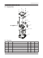
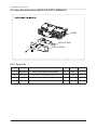
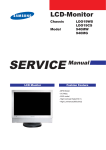
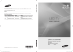
5. Exploded View & Part List
5. Exploded View & Part List
5-1. Exploded View
RB01
M0014
MA02A
SP01A
EF01
BP61-01828A
T001A
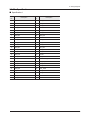
5-1-1. Parts List
Location No.
Code No.
Description & Specification
Q’ty
SA/SNA
EF01
BP31-00050A
FAN;H03,PLASTIC
2
SA
M0014
BP94-02396A
ASSY PCB MISC-MAIN;SP0351VBX/EN
1
SA
MA02A
BP94-02397A
ASSY PCB MISC-AV;SP0351VBX/EN
1
SA
RB01
BP63-01349A
COVER-BOTTOM;SP-H03,Mg D/C,BLK Splay
1
SA
SP01A
BN96-15061A
ASSY SPEAKER P;8ohm,2pin,1W,24.5mm
1
SA
T001A
BP96-02342C
ASSY COVER P-TOP;H03(DLP Logo),ABS,BLK
1
SNA
BP61-01828A
HOLDER-BOSS;H03,AL D/C,2
1
SNA
BP98-00776A
ASSY K/D-OPTIC MODULE;SP0351VBX/EN
1
SNA
Remark
5-1
5. Exploded View & Part List
5-2. Assy Exploded View (ASSY K/D-OPTIC MODULE)
GL02A
BP60-00135A
BP61-01840A
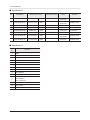
5-2-1. Parts List
Location No.
GL02A
5-2
Code No.
Description & Specification
Q’ty
SA/SNA
BP98-00776A
ASSY K/D-OPTIC MODULE;SP0351VBX/EN
1
SNA
BP96-02295A
ASSY LENS P-OPTIC MODULE;30lumen Pico pr
1
SA
BP60-00135A
SPACER-WASHER;H03,PPS,2,V0
1
SNA
BP61-01840A
HOLDER-LAMP-SCREW;H03(OBERON),STEEL,M1.6
2
SNA
Remark
5. Exploded View & Part List
5-3. Assy Exploded View (ASSY COVER P-TOP)
FC05
BP61-01827A
BP61-01825A
T001
FD01
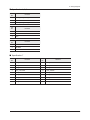
5-3-1. Parts List
Location No.
Code No.
Description & Specification
Q’ty
SA/SNA
T001A
BP96-02342C
ASSY COVER P-TOP;H03(DLP Logo),ABS,BLK
1
SNA
T001
BP63-01348A
COVER-TOP;SP-H03,ABS,Milky,Hotstamping,
1
SNA
FC05
BP63-01350B
COVER-JACK;H03(DLP Logo),PC,BLK,PC/SILIC
1
SNA
FD01
BP63-01351A
COVER-DECORATION;SP-H03,Others,0.25T,Ni
1
SNA
BP61-01825A
HOLDER-FOCUS;SP-H03,PC,BLK
1
SNA
BP61-01827A
HOLDER-PLATE;SP-H03,POM,BLK
1
SNA
Remark
5-3
5. Exploded View & Part List
5-4. Service Parts List
Description
MAIN BOARD
Code No.
BP94-02396A
DMD_LED DRIVER
BP94-02398A
AV BOARD
BP94-02397A
FAN
BP31-00050A
SPEAKER
BN96-15061A
ASSY LENS P-OPTIC MODULE
BP96-02295A
5-4
shape
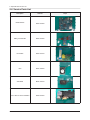
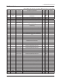
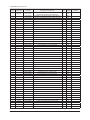
5. Exploded View & Part List
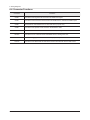
5-5. Parts List
Service Bom (SA: SERVICE AVAILABLE, SNA: SERVICE NOT AVAILABLE)
Level
Location No.
Code No.
Description & Specification
Q’ty
SA/SNA
0.1
ACCE1
BN92-06806A
ASSY ACCESSORY;SP0351VBX/XF
1
SNA
..2
ACCE1
BP96-02424A
ASSY ACCESSORY;SP0351VBX/XF
1
SNA
1
SNA
...3
T0527
AA68-00764A
LABEL-PASSING;SAMSUNG ALL,ART
PAPER,CLR,
...3
T0527
BN68-00513A
LABEL-E,PASS;ALL MODEL,YUPO(110G),50X15,
1
SNA
...3
BN69-05326A
BOX-IB;PICO(SP-H03),PAPER,NON-STANDARD M
1
SNA
...3
BP59-00143A
S/W DRIVER-01,IB;SP-H03,24Lang,W/W,Obero
1
SNA
...3
BP68-00655B
MANUAL FLYER-CAUTION;SP-H03,Samsung,19La
1
SNA
...3
BP68-00682B
MANUAL FLYER-WARRANTY
CARD;comm,Samsung,
1
SNA
...3
BP68-00697C
MANUAL FLYER-FERRITE CORE;SPH03,Samsung
1
SNA
...3
BP68-00697B
MANUAL FLYER-01,QSG;SP-H03,Samsung,7Lang
1
SNA
..2
ACCE1
BP96-02425A
ASSY ACCESSORY;SP0351VBX/XF
1
SNA
...3
T0121
3301-001502
CORE-FERRITE;16.5x7x30mm
1
SNA
...3
T0268
3903-000381
CBF-POWER CORD;DT,CHINA,LSG-21,250/250V,
1
SA
...3
M0158
BN44-00133C
DC VSS(A);SAD1212,IPANEMA/SWAN,110/230V,
1
SA
BN69-05325A
BOX-ACCESSORY;PICO(SP-H03),PAPER,NONSTA
1
SNA
BP96-02388A
ASSY ACCESSORY;PICO EN
1
SNA
6902-001266
BAG ZIPPER;LDPE,T0.05,W100,L150,TRP,SUF
1
SNA
BN39-01154E
CBF SIGNAL;Chelsea Slim, STEREO Plug to
1
SA
BN39-01154K
CBF SIGNAL-D SUB
GENDER;UE40C7700WSXZG,1
1
SA
...3
...3
ACCE1
....4
....4
M0114
....4
....4
GK39-00013C
CBF INTERFACE-USB;MYGENIE(DMB 10"),4P/5P
1
SA
0.1
T0725
BP90-00485A
ASSY COVER TOP;SP0351VBX/EN
1
SNA
..2
BP61-01838A
HOLDER-LAMPSCREW;H03(OBERON),STEEL,M2,L
4
SNA
..2
BP61-01839A
HOLDER-LAMPSCREW;H03(OBERON),STEEL,M1.4
1
SNA
..2
BP63-01353A
SHEET-PAD H/S;H03,GP3000S30,0.5T,5,21.4
1
SNA
..2
BP98-00776A
ASSY K/D-OPTIC MODULE;SP0351VBX/EN
1
SNA
...3
BP60-00135A
SPACER-WASHER;H03,PPS,2,V0
1
SNA
BP61-01840A
HOLDER-LAMPSCREW;H03(OBERON),STEEL,M1.6
2
SNA
...3
...3
GL02A
BP96-02295A
ASSY LENS P-OPTIC MODULE;30lumen Pico pr
1
SA
....4
GD09
4719-002434
DLP;0.3" DMD,S220, DDR,854x480 WVGA
1
SA
....4
GL09
BP07-00094A
LED DISPLAY;RED,PT16, RED, Type CX, G2.4
1
SA
....4
GL09
BP07-00095A
LED DISPLAY;GREEN,PT16, GREEN, Type CX,
1
SA
....4
GL09
BP07-00096A
LED DISPLAY;BLUE,PT16, BLUE, Type CX, G2
1
SA
...3
GD01A
BP94-02398A
ASSY PCB MISC-DMD;SP0351VBX/EN
1
SA
....4
0202-001463
SOLDER-WIRE;LFC2-W3.0,-,D3,99.79Sn/0.2Cu
....4
0204-002420
SOLVENT;1M-1000,C3H70H,96
....4
0204-002607
FLUX;DF-234U,13%,14KG,Gravity 0.82
....4
0202-001608
SOLDER-WIRE FLUX;LFC7-107,D0.8,99.3Sn/0.
....4
BP97-01456A
ASSY SMD;SP0351VBX/EN,301
.....5
.....5
.....5
D0254
Remark
SNA
0.42
SNA
SNA
SNA
1
SNA
0202-001477
SOLDER-CREAM;LST309-M,D20~45um,96.5Sn/3A
0404-001373
DIODE-SCHOTTKY;PD3S160,60V,1000mA,PowerD
1
SNA
SNA
0505-002707
FET-SILICON;ZXMN2F34MATA,N,20V,8.5A,0.12
3
SA
5-5
5. Exploded View & Part List
Level
Location No.
Code No.
Description & Specification
Q’ty
SA/SNA
.....5
ND51C2
1001-001155
IC-ANALOG
MULTIPLEX;NC7SB3157P6X,CMOS,SC
3
SA
.....5
1105-002105
IC-MOBILE SDRAM;K4X56163PI-FGC6,Mobile D
1
SNA
.....5
1203-003505
IC-DC/DC CONVERTER;TPS65120,QFN,16P,3x3m
1
SA
.....5
1203-005673
IC-POSI.ADJUST REG.;TPS71501DCKR,SC-70,5
1
SA
.....5
1203-006287
IC-POSI.ADJUST REG.;MP2002DD,QFN,8P,3x2m
2
SA
.....5
1203-006341
IC-DC/DC CONVERTER;TPS63020DSJ,SON-14,14
1
SA
.....5
1204-003147
IC-VIDEO PROCESS;DPP2605,CTBGA,233P,10x1
1
SA
.....5
R105
2007-000138
R-CHIP;100ohm,5%,1/16W,TP,1005
4
SA
.....5
AR49
2007-000140
R-CHIP;1Kohm,5%,1/16W,TP,1005
4
SNA
.....5
R104
2007-000148
R-CHIP;10Kohm,5%,1/16W,TP,1005
3
SA
.....5
MR13
2007-000157
R-CHIP;47Kohm,5%,1/16W,TP,1005
1
SNA
.....5
DR39
2007-000162
R-CHIP;100Kohm,5%,1/16W,TP,1005
4
SNA
.....5
2007-000167
R-CHIP;390Kohm,5%,1/16W,TP,1005
1
SNA
.....5
R509
2007-000170
R-CHIP;1Mohm,5%,1/16W,TP,1005
2
SNA
.....5
R111
2007-000171
R-CHIP;0ohm,5%,1/16W,TP,1005
6
SNA
.....5
PR4
2007-000265
R-CHIP;1.8Kohm,1%,1/10W,TP,1608
3
SA
2007-000336
R-CHIP;120Kohm,1%,1/10W,TP,1608
1
SA
2007-000775
R-CHIP;33Kohm,5%,1/16W,TP,1005
1
SNA
.....5
2007-001113
R-CHIP;680Kohm,5%,1/8W,TP,2012
1
SA
.....5
2007-001295
R-CHIP;39ohm,5%,1/16W,TP,1005
2
SA
2007-001325
R-CHIP;3.3Kohm,5%,1/16W,TP,1005
4
SNA
2007-003016
R-CHIP;3Mohm,5%,1/16W,TP,1005
1
SC
2007-007107
R-CHIP;100Kohm,1%,1/16W,TP,1005
6
SNA
2007-007132
R-CHIP;15Kohm,1%,1/16W,TP,1005
1
SA
2007-007142
R-CHIP;10Kohm,1%,1/16W,TP,1005
2
SNA
.....5
.....5
.....5
R124
R326
.....5
.....5
R365
.....5
.....5
DR4
.....5
2007-007306
R-CHIP;100ohm,1%,1/16W,TP,1005
1
SNA
.....5
2007-007312
R-CHIP;20Kohm,1%,1/16W,TP,1005
1
SA
.....5
2007-007318
R-CHIP;1Kohm,1%,1/16W,TP,1005
4
SNA
.....5
2007-008121
R-CHIP;0.33ohm,5%,1/4W,TP,3216
2
SA
.....5
2007-008275
R-CHIP;30Kohm,1%,1/16W,TP,1005
3
SNA
.....5
2007-008294
R-CHIP;33ohm,1%,1/16W,TP,1005
1
SA
.....5
2007-008502
R-CHIP;499Kohm,1%,1/16W,TP,1005
1
SC
.....5
2007-010412
R-CHIP;365Kohm,1%,1/16W,TP,1005
1
SA
.....5
2007-010413
R-CHIP;22.6Kohm,1%,1/16W,TP,1005
3
SA
.....5
C409
2203-000292
C-CER,CHIP;0.01nF,5%,50V,C0G,1608
2
SA
.....5
AC139
2203-000491
C-CER,CHIP;2.2nF,10%,50V,X7R,1608
18
SA
.....5
AD480
2203-000761
C-CER,CHIP;330nF,10%,16V,X7R,TP,2012,-
3
SNA
.....5
AD480
2203-002285
C-CER,CHIP;10nF,10%,50V,X7R,1005
3
SNA
.....5
AC2
2203-002711
C-CER,CHIP;100nF,10%,25V,X7R,1608
1
SA
.....5
AD480
2203-005393
C-CER,CHIP;0.005nF,0.1pF,50V,NP0,TP,1005
1
SNA
.....5
VC37
2203-006048
C-CER,CHIP;100nF,10%,10V,X7R,TP,1005
18
SA
.....5
PC11
2203-006141
C-CER,CHIP;1000nF,10%,16V,X5R,1608
1
SNA
.....5
JC10
2203-006324
C-CER,CHIP;2200nF,10%,10V,X5R,1608
2
SA
.....5
C125
2203-006361
C-CER,CHIP;10000nF,10%,10V,X5R,TP,2012
3
SC
.....5
AD480
2203-006427
C-CER,CHIP;4700nF,10%,16V,X5R,TP,2012
1
SA
.....5
AD480
2203-006460
C-CER,CHIP;2200nF,10%,16V,X5R,1608
1
SA
.....5
HE4
2203-006474
C-CER,CHIP;22000nF,20%,6.3V,X5R,2012
5
SA
.....5
AD480
2203-006636
C-CER,CHIP;220nF,10%,25V,X7R,1608
3
SA
.....5
AD480
2203-006681
C-CER,CHIP;100nF,+80-20%,25V,Y5V,1005
1
SNA
5-6
Remark
5. Exploded View & Part List
Level
Location No.
Code No.
Description & Specification
Q’ty
SA/SNA
.....5
AD480
2203-006841
C-CER,CHIP;1000nF,10%,16V,X5R,1005
1
SNA
.....5
AD480
2203-006992
C-CER,CHIP;0.33nF,5%,50V,C0G,TP,1005
8
SNA
.....5
AD480
2203-007270
C-CER,CHIP;10000nF,10%,10V,X5R,TP,1608
9
SNA
.....5
T0052
2703-000125
INDUCTOR-SMD;10uH,10%,2012
1
SA
.....5
T0052
2703-003252
INDUCTOR-SMD;1.2uH,20%,5050
1
SA
2804-001906
OSCILLATOR-CLOCK;33.333300MHz,50ppm,15pF
1
SA
.....5
.....5
T0568
3301-001236
BEAD-SMD;60ohm,1608
1
SNA
.....5
T0568
3301-002039
BEAD-SMD;26ohm,1608,TP
17
SA
.....5
3708-002848
CONNECTOR-FPC/FFC/PIC;18P,0.5mm,SMD-A,AU
1
SA
.....5
BP97-01460A
ASSY MICOM-DMD;SP-H03,PROJECT
1
SNA
......6
1107-001916
IC-NOR FLASH;W25Q16BVSSIG,16Mbit,2Mbitx8
1
SNA
.....5
3710-002957
SOCKET-BOARD TO
BOARD;50P,2R,0.4mm,SMD-S
2
SNA
.....5
BP41-00399B
PCB MAIN;SP-H03,FR-4,8,1.0,0.7,63*43,OBE
1
SNA
..2
BP98-00789A
ASSY K/D-FAN;SP0351VBX/EN
1
SNA
...3
BP31-00050A
FAN;H03,PLASTIC
2
SA
...3
EF01
BP72-00127A
SPONGE;H03,URETHANE,3,FAN
2
SNA
...3
BP74-01002A
TAPE-ETC;H03,T1.0,V0
2
SNA
...3
BP74-01005A
TAPE-ETC;H03,T0.08,33x33,BLACK
2
SNA
..2
T001A
BP96-02342C
ASSY COVER P-TOP;H03(DLP Logo),ABS,BLK
1
SNA
...3
CCM1
BN63-02183C
COVER-SHEET;Rhcm,PE Vinyl,T0.04,200mm,20
0.2
SNA
...3
BP61-01825A
HOLDER-FOCUS;SP-H03,PC,BLK
1
SNA
...3
BP61-01827A
HOLDER-PLATE;SP-H03,POM,BLK
1
SNA
BP63-01348A
COVER-TOP;SP-H03,ABS,Milky,Hotstamping,
1
SNA
...3
T001
....4
T0254
BN60-00113A
FASTENER-PEM NUT;PAPYRUS,SUM24L,M1.4,10.
2
SNA
...3
FC05
BP63-01350B
COVER-JACK;H03(DLP Logo),PC,BLK,PC/SILIC
1
SNA
...3
FD01
BP63-01351A
COVER-DECORATION;SP-H03,Others,0.25T,Ni
1
SNA
...3
BP61-01828A
HOLDER-BOSS;H03,AL D/C,2
1
SNA
...3
BP61-01839A
HOLDER-LAMPSCREW;H03(OBERON),STEEL,M1.4
1
SNA
...3
BP63-01382A
GASKET;SP-H03,FOIL,1,11.5,18.8,SILVER
1
SNA
...3
BP96-02365A
ASSY BOARD P-TOUCH PAD;Oberon,CT5000-806
1
SNA
BP96-02376B
ASSY CABLE P-FFC;SP-H03,FFC CABLE,40MM,1
1
SNA
BP90-00486A
ASSY COVER BOTTOM;SP0351VBX/EN
1
SNA
BP63-01349A
COVER-BOTTOM;SP-H03,Mg D/C,BLK Splay
1
SA
...3
FL06
0.1
..2
RB01
..2
BP73-00161A
RUBBER-FOOT;SP-H03,SILICON,BLK
4
SNA
0.1
BP91-02189A
ASSY MISC-CHASSIS;SP0351VBX/EN
1
SNA
1
BP94-02396A
ASSY PCB MISC-MAIN;SP0351VBX/EN
...3
..2
M0014
0202-001463
SOLDER-WIRE;LFC2-W3.0,-,D3,99.79Sn/0.2Cu
...3
0204-002420
SOLVENT;1M-1000,C3H70H,96
...3
0204-002607
FLUX;DF-234U,13%,14KG,Gravity 0.82
...3
0202-001608
SOLDER-WIRE FLUX;LFC7-107,D0.8,99.3Sn/0.
...3
BP97-01454A
ASSY SMD;SP0351VBX/EN,301
....4
SA
SNA
3.91
SNA
SNA
SNA
1
SNA
0202-001477
SOLDER-CREAM;LST309-M,D20~45um,96.5Sn/3A
....4
MZD1
0403-001411
DIODE-ZENER;5.49-5.73V,200mW,SOD-323,TP
3
SA
....4
D0254
0404-001404
DIODE-SCHOTTKY;BAT721C,40V,200mA,SOT-23,
1
SA
0501-000434
TR-SMALL SIGNAL;KTC3875SGR,NPN,150mW,SO
4
SA
....4
Remark
SNA
....4
Q409
0505-001905
FET-SILICON;2N7002,N,60V,115mA,7.5ohm,0.
19
SA
....4
Q409
0505-002386
FET-SILICON;AO3415AL,P,-20V,-4A,0.045ohm
7
SA
5-7
5. Exploded View & Part List
Level
Location No.
....4
....4
ND51C2
Code No.
Description & Specification
Q’ty
SA/SNA
0902-002562
IC-MICROPROCESSOR;TCC9101G0BX,120Mhz,FP
1
SA
1001-001155
IC-ANALOG
MULTIPLEX;NC7SB3157P6X,CMOS,SC
1
SA
....4
1002-001556
IC-A/D&D/A CONVERTER;CS42L52CNZR,8,QFN,4
1
SNA
....4
1105-001859
IC-DDR2 SDRAM;K4T1G164QD-ZCE7,DDR2,1Gbit
1
SA
1203-004363
IC-VOL. DETECTOR;RT9818C-29PV,SOT-23,3P,
1
SA
1203-004618
IC-SWITCH REG.;MP3213DH,MSOP,8P,3x3mm,PL
1
SA
....4
1203-005923
IC-DC/DC CONVERTER;TPS63031DSKR,QFN,10P,
1
SA
....4
1203-006127
IC-DC/DC CONVERTER;MP28253EL,QFN,14P,3x4
1
SA
....4
1203-006196
IC-BATTERY;MAX8903AETI+T,TQFN,28P,4x4mm,
1
SA
....4
1203-006287
IC-POSI.ADJUST REG.;MP2002DD,QFN,8P,3x2m
1
SA
....4
1203-006347
IC-DC/DC CONVERTER;MP2125DL,QFN,14P,3x4m
1
SA
....4
1204-003174
IC-VIDEO PROCESS;TW8816-BB3-GR,TFBGA,144
1
SNA
....4
1405-001233
VARISTOR;30Vdc,5A,1.6x0.8x0.8mm,TP
11
SA
....4
....4
IC150
....4
ND51C2
2007-000066
R-CHIP;20Kohm,1%,1/10W,TP,1608
1
SNA
....4
R512
2007-000107
R-CHIP;470Kohm,5%,1/10W,TP,1608
1
SA
....4
MR604
2007-000137
R-CHIP;2Kohm,5%,1/16W,TP,1005
5
SNA
....4
R105
2007-000138
R-CHIP;100ohm,5%,1/16W,TP,1005
5
SA
....4
AR49
2007-000140
R-CHIP;1Kohm,5%,1/16W,TP,1005
6
SNA
....4
R319
2007-000143
R-CHIP;4.7Kohm,5%,1/16W,TP,1005
12
SNA
....4
RR33
2007-000154
R-CHIP;24Kohm,5%,1/16W,TP,1005
1
SA
....4
AR43
2007-000155
R-CHIP;27Kohm,5%,1/16W,TP,1005
1
SNA
....4
MR13
2007-000157
R-CHIP;47Kohm,5%,1/16W,TP,1005
5
SNA
....4
DR39
2007-000162
R-CHIP;100Kohm,5%,1/16W,TP,1005
5
SNA
....4
VR9
2007-000164
R-CHIP;150Kohm,5%,1/16W,TP,1005
1
SA
....4
R111
2007-000171
R-CHIP;0ohm,5%,1/16W,TP,1005
72
SNA
....4
UR23
2007-000174
R-CHIP;47ohm,5%,1/16W,TP,1005
1
SNA
....4
ER13
2007-000669
R-CHIP;2Kohm,1%,1/10W,TP,1608
6
SNA
....4
R945
2007-000726
R-CHIP;300ohm,1%,1/10W,TP,1608
1
SA
....4
V8932
2007-000857
R-CHIP;4.3Kohm,1%,1/10W,TP,1608
1
SNA
....4
OTR1
2007-001292
R-CHIP;33ohm,5%,1/16W,TP,1005
5
SNA
....4
2007-001295
R-CHIP;39ohm,5%,1/16W,TP,1005
8
SA
....4
MR31
2007-001305
R-CHIP;120ohm,5%,1/16W,TP,1005
1
SNA
....4
CER07
2007-001308
R-CHIP;200ohm,5%,1/16W,TP,1005
2
SNA
2007-007008
R-CHIP;300ohm,5%,1/16W,TP,1005
2
SNA
2007-007107
R-CHIP;100Kohm,1%,1/16W,TP,1005
8
SNA
....4
2007-007132
R-CHIP;15Kohm,1%,1/16W,TP,1005
1
SA
....4
2007-007134
R-CHIP;39Kohm,1%,1/16W,TP,1005
1
SA
....4
....4
R365
....4
2007-007136
R-CHIP;4.7Kohm,1%,1/16W,TP,1005
9
SNA
....4
DR4
2007-007142
R-CHIP;10Kohm,1%,1/16W,TP,1005
40
SNA
....4
MR601
2007-007307
R-CHIP;150ohm,1%,1/16W,TP,1005
1
SNA
....4
2007-007309
R-CHIP;12Kohm,1%,1/16W,TP,1005
2
SA
....4
2007-007318
R-CHIP;1Kohm,1%,1/16W,TP,1005
7
SNA
....4
2007-007573
R-CHIP;330Kohm,1%,1/16W,TP,1005
1
SC
2007-007651
R-CHIP;9.1Kohm,1%,1/10W,TP,1608
1
SA
....4
R133
....4
2007-007733
R-CHIP;51ohm,1%,1/10W,TP,1608
2
SA
....4
2007-007797
R-CHIP;44.2ohm,1%,1/10W,TP,1608
1
SA
....4
2007-007942
R-CHIP;1Mohm,1%,1/16W,TP,1005
2
SA
....4
2007-008035
R-CHIP;160Kohm,1%,1/10W,TP,1608
1
SA
5-8
Remark
5. Exploded View & Part List
Level
Location No.
Code No.
Description & Specification
Q’ty
SA/SNA
....4
2007-008263
R-CHIP;3Kohm,1%,1/16W,TP,1005
2
SNA
....4
2007-008275
R-CHIP;30Kohm,1%,1/16W,TP,1005
1
SNA
....4
2007-008296
R-CHIP;680Kohm,1%,1/16W,TP,1005
1
SNA
....4
2007-010406
R-CHIP;412Kohm,1%,1/16W,TP,1005
1
SA
....4
2007-010412
R-CHIP;365Kohm,1%,1/16W,TP,1005
1
SA
ZRN10
2011-001261
R-NETWORK;33ohm,5%,1/16W,L,CHIP,8P,TP,2.
6
SA
2011-001427
R-NETWORK;0ohm,5%,1/16W,L,CHIP,8P,TP,2.0
7
SA
....4
MC2
2203-000254
C-CER,CHIP;10nF,10%,16V,X7R,TP,1005
2
SA
....4
C409
2203-000292
C-CER,CHIP;0.01nF,5%,50V,C0G,1608
1
SA
....4
VC4
2203-000357
C-CER,CHIP;0.15nF,5%,50V,C0G,1608
4
SNA
....4
DC1
2203-000386
C-CER,CHIP;.015nF,5%,50V,C0G,TP,1005
2
SA
....4
C137
2203-000604
C-CER,CHIP;22nF,10%,25V,X7R,TP,1608
2
SNA
....4
AD480
2203-001391
C-CER,CHIP;150nF,10%,25V,X7R,TP,2012
1
SA
....4
AC28
2203-001607
C-CER,CHIP;0.22nF,5%,50V,NP0,1608
2
SA
....4
AD480
2203-002285
C-CER,CHIP;10nF,10%,50V,X7R,1005
4
SNA
....4
....4
....4
AC2
2203-002711
C-CER,CHIP;100nF,10%,25V,X7R,1608
2
SA
....4
C155
2203-002834
C-CER,CHIP;0.022nF,5%,50V,CH,BK,1005
2
SNA
....4
AD480
2203-006126
C-CER,CHIP;47nF,10%,16V,X7R,1005
1
SNA
....4
C102
2203-006158
C-CER,CHIP;100nF,10%,16V,X7R,1005
109
SNA
....4
JC10
2203-006324
C-CER,CHIP;2200nF,10%,10V,X5R,1608
1
SA
....4
AD480
2203-006336
C-CER,CHIP;10000nF,10%,25V,X5R,3216
2
SA
....4
C125
2203-006361
C-CER,CHIP;10000nF,10%,10V,X5R,TP,2012
45
SC
....4
AD480
2203-006377
C-CER,CHIP;4700NF,10%,25V,X5R,-,2012
1
SNA
....4
HDC11
2203-006562
C-CER,CHIP;1000nF,10%,10V,X5R,TP,1005
13
SNA
....4
AD480
2203-006824
C-CER,CHIP;4700nF,10%,10V,X5R,1608
3
SNA
....4
AD480
2203-007270
C-CER,CHIP;10000nF,10%,10V,X5R,TP,1608
1
SNA
....4
S1Q0552
2703-000371
INDUCTOR-SMD;4.7uH,5%,2520
2
SA
....4
T0052
2703-003150
INDUCTOR-SMD;4.7uH,20%,5050
2
SNA
....4
T0052
2703-003252
INDUCTOR-SMD;1.2uH,20%,5050
3
SA
....4
T0052
2703-003718
INDUCTOR-SMD;2.2uH,20%,3.8x3.8x2.0mm
1
SA
....4
X202
2801-004868
CRYSTAL-SMD;12MHz,50ppm,8pF,100ohm,TP
1
SA
....4
X202
2801-004885
CRYSTAL-SMD;27MHz,50ppm,BMC-30,18pF,100o
1
SA
....4
T0568
3301-001594
BEAD-SMD;90ohm,2.0*1.2*1.3mm,TP,-,-
1
SNA
....4
T0568
3301-002039
BEAD-SMD;26ohm,1608,TP
35
SA
....4
AC510
3708-002624
CONNECTOR-FPC/FFC/PIC;8P,0.5mm,SMD-A,AU,
1
SA
3708-002849
CONNECTOR-FPC/FFC/PIC;14P,0.5mm,SMD-A,AU
2
SA
....4
3709-001527
CONNECTOR-CARD EDGE;10P,8mm,AU,MICRO
SD
1
SNA
....4
3711-005980
HEADERBATTERY;NOWALL,3P,1R,2mm,BATTERY,
1
SNA
....4
3711-007476
HEADER-BOARD TO
BOARD;BOX,50P,2R,0.4mm,S
1
SA
3722-002528
JACK-USB;5P,AU30U,BLK,SMD-A,MINI USB B
1
SA
1209-001880
IC-SENSOR;BDE0900G,SSOP5,5P,2.9x1.6x1.25
1
SNA
1405-001232
VARISTOR;5.6Vdc,30A,1.6x0.8x0.8mm,TP
2
SNA
2007-001320
R-CHIP;1.8Kohm,5%,1/16W,TP,1005
1
SA
....4
2007-007315
R-CHIP;3.9Kohm,1%,1/16W,TP,1005
1
SNA
....4
2007-007791
R-CHIP;9.1Kohm,1%,1/16W,TP,1005
1
SNA
BP97-01465A
ASSY MICOM-MAIN;H03
1
SNA
1107-001774
IC-NAND FLASH;K9G8G08U0A-PCB0,1GByte,1Gx
1
SNA
....4
....4
....4
IS01
....4
....4
HR10
....4
.....5
NAND2
Remark
5-9
5. Exploded View & Part List
Level
Location No.
....4
Code No.
Description & Specification
Q’ty
SA/SNA
BP97-01466A
ASSY MICOM-SUB;H03
1
SNA
.....5
IC115
1107-001614
IC-FLASH MEMORY;MX25L1005,1Mbit,1Mx1,SOP
1
SNA
....4
D2507
0402-001075
DIODE-RECTIFIER;MBR0520L,20V,.5A,SOD-123
1
SNA
....4
EH01
3711-006941
HEADER-BOARD TO CABLE;BOX,3P,1R,1.25mm,S
3
SNA
....4
3722-003056
JACK-PHONE;1P/6C,AU,BLK,SMD-A
1
SA
....4
3722-003108
JACK-DC POWER;1P,1.65PI,SN,BLK
1
SA
....4
0406-001181
DIODE-TVS;NUP4201MR6,6/-/-V,500W,TSOP-6
1
SA
....4
BP41-00398B
PCB MAIN;SP-H03,FR-4,8,MP1.0,1,66x66mm,O
1
SNA
1
BP94-02397A
ASSY PCB MISC-AV;SP0351VBX/EN
...3
..2
MA02A
0202-001463
SOLDER-WIRE;LFC2-W3.0,-,D3,99.79Sn/0.2Cu
SA
...3
0204-002420
SOLVENT;1M-1000,C3H70H,96
...3
0204-002607
FLUX;DF-234U,13%,14KG,Gravity 0.82
...3
BP97-01455A
ASSY SMD;SP0351VBX/EN,301
....4
0202-001477
SOLDER-CREAM;LST309-M,D20~45um,96.5Sn/3A
....4
0403-001180
DIODE-ZENER;BZX84C6V2,5.8-6.6V,350mW,SOT
2
SA
SNA
2.62
SNA
SNA
1
SNA
SNA
....4
D0254
0404-001404
DIODE-SCHOTTKY;BAT721C,40V,200mA,SOT-23,
2
SA
....4
Q101
0501-000445
TR-SMALL SIGNAL;KTC3875S-Y,NPN,150mW,SOT
1
SA
....4
1405-001233
VARISTOR;30Vdc,5A,1.6x0.8x0.8mm,TP
12
SA
....4
R105
2007-000138
R-CHIP;100ohm,5%,1/16W,TP,1005
10
SA
....4
MR13
2007-000157
R-CHIP;47Kohm,5%,1/16W,TP,1005
4
SNA
....4
R111
2007-000171
R-CHIP;0ohm,5%,1/16W,TP,1005
1
SNA
....4
R124
2007-000775
R-CHIP;33Kohm,5%,1/16W,TP,1005
2
SNA
....4
DR4
2007-007142
R-CHIP;10Kohm,1%,1/16W,TP,1005
3
SNA
....4
MR11
2007-008015
R-CHIP;75ohm,1%,1/16W,TP,1005
4
SNA
....4
C258
2203-000236
C-CER,CHIP;0.1nF,5%,50V,C0G,1608
4
SA
....4
AD480
2203-000550
C-CER,CHIP;0.02nF,5%,50V,C0G,1005
4
SNA
....4
C125
2203-006361
C-CER,CHIP;10000nF,10%,10V,X5R,TP,2012
1
SC
....4
T0052
2703-000125
INDUCTOR-SMD;10uH,10%,2012
2
SA
....4
BD401
3301-001569
BEAD-SMD;600ohm,2012,1000mA,TP,520ohm/90
1
SNA
3708-002849
CONNECTOR-FPC/FFC/PIC;14P,0.5mm,SMD-A,AU
1
SA
3711-007346
CONNECTORHEADER;BOX,18P,1R,0.6mm,SMD-A,
1
SA
....4
....4
CN906
BP97-01459A
ASSY MICOM-AV;SP-H03,PROJECT
1
SNA
.....5
....4
IC112
1103-001310
IC-EEPROM;24LC02B,256X8BIT,SOIC,8P,3.91X
1
SNA
....4
JA330
3722-002845
JACK-PHONE;1/7P,NI,YELLOW,ANGLE
1
SA
1
SNA
....4
BP41-00400B
PCB MAIN;SP-H03,FR-4,2,1,23*20,8
...3
0202-001608
SOLDER-WIRE FLUX;LFC7-107,D0.8,99.3Sn/0.
0.1
SNA
BP91-02190A
ASSY FIXING;SP0351VBX/EN
1
SNA
BN96-15061A
ASSY SPEAKER P;8ohm,2pin,1W,24.5mm
1
SA
..2
BP43-01001A
BATTERY;1102-01960D,SP-H03,Li-ion,2,1480
1
SA
..2
BP63-01380A
GASKET;SP-H03,FOIL,9,5,20,SILVER
1
SNA
BP63-01381A
GASKET;SP-H03,FOIL,3,5,15,SILVER
1
SNA
BP96-02376A
ASSY CABLE P-FFC;SP-H03,FFC CABLE,40MM,1
1
SNA
BP92-02202A
ASSY BOX;SP0351VBX/EN
1
SNA
BN69-05235A
BOX-01,SET;PICO,PAPER,NON-STANDARD
MANIL
1
SNA
BN69-05251A
BOX-01,MASTER;PICO,CB,A-01,SW2, YEL,W477
1
SNA
AA68-02789A
LABEL-00,BAR,SERIAL;MOJO,80,50,WHT,BARCO
1
SNA
BN68-02398A
LABEL-02,SEALING;E5(E-BOOK),art paper,w5
2
SNA
BN68-00134L
LABEL-BOX,01;ALL MODEL,MOJO 90G,120X90,W
1
SNA
..2
SP01A
..2
..2
FL06
0.1
..2
..2
..2
T0527
..2
..2
5-10
T0527
Remark
5. Exploded View & Part List
Level
Location No.
Code No.
Description & Specification
Q’ty
SA/SNA
0.1
BP92-02203A
ASSY P/MATERIAL;SP0351VBX/EN
1
SNA
..2
6902-000061
BAG AIR;LDPE,T0.2,W500,L1000,TRP,370.000
1
SNA
..2
6902-000379
BAG AIR;LDPE,T0.2,W1000,L1800,TRP,1260.0
1
SNA
..2
6902-000604
BAG WRAPPING;LDPE,T0.02,W500,L10000,TRP,
0.7
SNA
..2
6902-000609
BAG ROLL;LDPE,T0.05,W2400,L1000,TRP,30.0
0.02
SNA
..2
BH69-00457B
PACKING INNER-00,PAD;COMM,OTHER,T3.0,930
1
SNA
..2
BH69-40383M
PACKING INNER-00,PAD;COMM,CB,1000,800,YE
1
SNA
..2
BN69-00391Y
PAD-ANGLE;CB,T5,W2100,L50,YEL,403g
1
SNA
..2
BN69-00617M
PALLET-PACKING;RL17PS,WOOD,1280,970,120
1
SNA
..2
6902-000457
BAG PE;LDPE,T0.05,W140,L210,CLR
1
SNA
..2
..2
..2
T0214
BP63-01370A
COVER-BAG;SP-H03,Textile,PAUCH
1
SNA
0203-001269
TAPE-OPP MASKING;#301,T0.06,W75,L50000,N
0.13
SNA
6902-001284
BAG PE;HDPE/NITRON,T0.015/T0.5,W120,L140
1
SNA
0.1
BP92-02243A
ASSY LABEL;OBERON
1
SNA
..2
BN68-02132A
LABEL-RATING;PET,T0.05,50,32,W/W
1
SNA
Remark
5-11
1. Precautions
1. Precautions
1-1. Safety Precautions
Follow these safety, servicing and ESD precautions to prevent damage and to protect against potential hazards such as
electrical shock.
1-1-1. Warnings
1. Do not modify the circuits of the product for safety reasons.
2. Do not supply power to your product before a service engineer has serviced it.
3. When the monitor is operating, the product may receive a shock due to the semiconductor heat sink.
1-1-2. Servicing the LCD Monitor
1. When servicing the LCD Monitor, Disconnect the AC line cord from the AC outlet.
2. It is essential that service technicians have an accurate voltage meter available at all times. Check the calibration of
this meter periodically.
1-1-3. Fire and Shock Hazard
Before returning the monitor to the user, perform the following safety checks:
1. Inspect each lead dress to make certain that the leads are not pinched or that hardware is not lodged between the
chassis and other metal parts in the monitor.
2. Inspect all protective devices such as nonmetallic control knobs, insulating materials, cabinet backs, adjustment and
compartment covers or shields, isolation resistorcapacitor networks, mechanical insulators, etc.
3. Leakage Current Hot Check (Figure 1-1):
WARNING : Do not use an isolation transformer during this test.
(READING SHOULD)
NOT BE ABOVE 0.5mA
LEAKAGE
CURRENT
TESTER
DEVICE
UNDER
TEST
TEST ALL
EXPOSED METAL
SURFACES
2-WIRE CORD
*ALSO TEST WITH
PLUG REVERSED
(USING AC ADAPTER
PLUG AS REQUIRED)
EARTH
GROUND
Figure 1-1. Leakage Current Test Circuit
Use a leakage current tester or a metering system that complies with American National Standards Institute (ANSI
C101.1, Leakage Current for Appliances), and Underwriters Laboratories (UL Publication UL1410, 59.7).
4. With the unit completely reassembled, plug the AC line cord directly into a 120V AC outlet. With the unit’s AC switch
first in the ON position and then OFF, measure the current between a known earth ground (metal water pipe, conduit,
etc.) and all exposed metal parts, including: metal cabinets, screwheads and control shafts.
The current measured should not exceed 0.5 milliamp.
Reverse the power-plug prongs in the AC outlet and repeat the test.
1-1-4. Product Safety Notices
Some electrical and mechanical parts have special safetyrelated characteristics which are often not evident from visual
inspection. The protection they give may not be obtained by replacing them with components rated for higher voltage,
wattage, etc. Parts that have special safety characteristics are identified by
on schematics and parts lists. A substitute
replacement that does not have the same safety characteristics as the recommended replacement part might create
shock, fire and/or other hazards. Product safety is under review continuously and new instructions are issued whenever
appropriate.
1-1
1. Precautions
1-2. Servicing Precautions
WARNING: An electrolytic capacitor installed with the wrong polarity might explode.
Caution:
Before servicing units covered by this service manual, read and follow the Safety Precautions section of
this manual.
Note:
If unforeseen circumstances create conflict between the following servicing precautions and any of the
safety precautions, always follow the safety precautions.
1-2-1 General Servicing Precautions
1. Always unplug the unit’s AC power cord from the AC power source and disconnect the DC Power Jack before
attempting to:
(a) remove or reinstall any component or assembly, (b) disconnect PCB plugs or connectors, (c) connect a test
component in parallel with an electrolytic capacitor.
2. Some components are raised above the printed circuit board for safety. An insulation tube or tape is sometimes
used. The internal wiring is sometimes clamped to prevent contact with thermally hot components. Reinstall all such
elements to their original position.
3. After servicing, always check that the screws, components and wiring have been correctly reinstalled. Make sure that
the area around the serviced part has not been damaged.
4. Check the insulation between the blades of the AC plug and accessible conductive parts (examples: metal panels,
input terminals and earphone jacks).
5. Insulation Checking Procedure: Disconnect the power cord from the AC source and turn the power switch ON.
Connect an insulation resistance meter (500 V) to theblades of the AC plug.
The insulation resistance between each blade of the AC plug and accessible conductive parts (see above) should be
greater than 1 megohm.
6. Always connect a test instrument’s ground lead to the instrument chassis ground before connecting the positive lead;
always remove the instrument’s ground lead last.
1-3. Static Electricity Precautions
Some semiconductor (solid state) devices can be easily damaged by static electricity. Such components are commonly
called Electrostatically Sensitive Devices (ESD). Examples of typical ESD are integrated circuits and some field-effect
transistors. The following techniques will reduce the incidence of component damage caused by static electricity.
1. Immediately before handling any semiconductor components or assemblies, drain the electrostatic charge from your
body by touching a known earth ground. Alternatively, wear a discharging wrist-strap device. To avoid a shock hazard,
be sure to remove the wrist strap before applying power to the monitor.
2. After removing an ESD-equipped assembly, place it on a conductive surface such as aluminum foil to prevent
accumulation of an electrostatic charge.
3. Do not use freon-propelled chemicals. These can generate electrical charges sufficient to damage ESDs.
4. Use only a grounded-tip soldering iron to solder or desolder ESDs.
5. Use only an anti-static solder removal device. Some solder removal devices not classified as “anti-static” can generate
electrical charges sufficient to damage ESDs.
6. Do not remove a replacement ESD from its protective package until you are ready to install it. Most replacement ESDs
are packaged with leads that are electrically shorted together by conductive foam, aluminum foil or other conductive
materials.
7. Immediately before removing the protective material from the leads of a replacement ESD, touch the protective
material to the chassis or circuit assembly into which the device will be installed.
Caution: Be sure no power is applied to the chassis or circuit and observe all other safety precautions.
8. Minimize body motions when handling unpackaged replacement ESDs. Motions such as brushing clothes together,
or lifting your foot from a carpeted floor can generate enough static electricity to damage an ESD.
1-2
1. Precautions
1-4. Installation Precautions
1. For safety reasons, more than two people are required for carrying the product.
2. Keep the power cord away from any heat emitting devices, as a melted covering may cause fire or electric shock.
3. Do not place the product in areas with poor ventilation such as a bookshelf or closet. The increased internal
temperature may cause fire.
4. Bend the external antenna cable when connecting it to the product. This is a measure to protect it from being exposed
to moisture. Otherwise, it may cause a fire or electric shock.
5. Make sure to turn the power off and unplug the power cord from the outlet before repositioning the product. Also check
the antenna cable or the external connectors if they are fully unplugged. Damage to the cord may cause fire or electric
shock.
6. Keep the antenna far away from any high-voltage cables and install it firmly. Contact with the highvoltage cable or the
antenna falling over may cause fire or electric shock.
7. When installing the product, leave enough space (10cm) between the product and the wall for ventilation purposes.
A rise in temperature within the product may cause fire.
1-3
1. Precautions
Memo
1-4
2. Product specifications
2. Features and Specifications
2-1. Features and Specifications
Model
SP-H03
Features
ሪሪ Max 30 lumen/WVGA-level PICO projector
ሪሪ Eco projector, which uses LEDs that do not need to be replaced.
ሪሪ Rich colors from red, green and blue LEDs
ሪሪ Multimedia and document viewer functions (USBs and MicroSD cards)
ሪሪ More convenient to use, stand-alone projector integrated with a document viewer and M/M viewer
ሪሪ Equipped with a 1 W mono speaker and a manual focus feature
ሪሪ High capacity battery, which should last through a conference or movie after one full charge
2-1
2. Product specifications
2-2. Major Specifications
Major Specifications
Model
Panel
Size
0.3inch
Resolution
WVGA (854 x 480)
Aspect ratio
Power
LED Light Source
16 : 9
Power Consumption
TYP. 8.5W (Operating at Battery)
100 ~ 240 V AC, 50/60 Hz
Power Consumption
4W
Life Time
30,000 Hours
70 x 70 x 27.5 mm / 2.76 x 2.76 x 1.08 inches (without the battery)
70 x 70 x 37.5 mm / 2.76 x 2.76 x 1.48 inches (with the battery)
Projector : 132 g / 0.29 lbs
Weight
Input signal
Max 12.0W (Operating & Charging at Adapter),
Voltage
Dimension (Width x Length x Height)
Key Features
SP-H03
Battery : 80 g / 0.18 lbs
Brightness
TYP 27, MAX 30 Lumen
Contrast
1000:1
Projection Range
30.5 ~ 299 cm / 12.00 ~ 117.71 inches
Keystone
<1%
Focus Adjustment
Manual
Screen Size
(Diagonal)
Diagonal 8.6 inches ~ 85.5 inches
D-Sub 15p
Analog RGB, Analog Y PB PR
Media play
USB, internal memory and MicroSD
RCA X 1
Composite video
Internal memory capacity
1 GB (System memory: 301 MB / User memory: 699 MB)
Speaker
1 W (Mono)
Operating : Temperature 32 °F ~ 104 °F (0 °C ~ 40 °C),
User Environment
Temperature and
Humidity
Humidity 10 % ~ 80 % (Non-condensing)
Storage : Temperature -4 °F ~ 113 °F (-20 °C ~ 45 °C),
Humidity 5 % ~ 95 % (Non-condensing)
Noise
2-2
23 dB
2. Product specifications
2-3. Spec Comparison to the Old Models
Model
SP-H03
SP-P410M
0.3”
0.55” Type-Y
854 x 480
800 x 600
30 ANSI lm
170 ANSI lm
1000 : 1
1000 : 1
More than 30,000 hours
More than 30,000 hours
9.1W
49W
8.6” to 85.5”
20” to 80”
Input Terminal
PC/VIDEO (using optional Gender cable)
USB (using optional Gender cable)
SD Micro CARD
PC / Video
(using common cable)
COMPONENT
(using optional Gender cable)
USB
Audio Output
1W mono
1W + 1W
Remote Control
X
TM91 (BN59-00900A)
Height Adjustment
X
O
Tripod Installation
O
O
Design
Panel
Brightness
Contrast
LED Lifetime
Power Consumption
Image Size
2-3
2. Product specifications
2-4. Accessories
Product
Description
Code. No
Quick Setup Guide
BP68-00697A
Warranty Card
(Not available in all locations)
-
User’s Guide
BP59-00143A
Power Cord / Adaptor
BN44-00133C
Remark
Samsung Electronics
Service center
BP43-01001A
USB Gender
GK39-00013C
3RCA Gender
BN39-01154E
D-Sub Gender
BN39-01154K
B
Battery
2-4
2. Product specifications
2-5. Precautions for Using a USB Storage Device
■ This projector does not support multi-card readers. It only supports USB storage devices.
■ Some USB devices may not be supported.
■ Some projectors which do not fully comply with the standard USB specifications may not operate normally.
■ This projector does not recognize a USB storage device connected via a USB hub.
■ A USB storage device integrated with an auto-reading application or internal driver may not be compatible with this
projector.
■ A USB memory device designed for only a certain driver may not be recognized.
■ The recognition speed of the USB storage device may vary.
■ While a USB storage device is in use, do not turn the projector off or remove the connected USB device. Forced removal
can cause damage to the USB device or files it contains.
■ Ensure that you only use a USB storage device that contains uncorrupted files. Otherwise, the projector may malfunction
or the files may not be opened.
■ Only a USB storage device formatted by the FAT or FAT32 (recommended) file system supported by Windows is
applicable. Storage devices formatted with an operating system other than Windows may not be compatible.
■ If you are using a device that requires an external power source, be sure to check the power cable is connected.
Otherwise, the projector may not recognize the device.
■ When connecting to the projector’s USB port, use the cable supplied with the USB. (Contact your USB service center for
more information on purchasing a cable or external device.)
■ We are not responsible for any damage to an external device caused by using a cable that does not comply with the
device’s designated specifications.
■ As data on a USB storage device can be damaged, ensure that you back up important data. We are not responsible for
any loss of data.
■ There are some limitations when accessing files saved on a USB storage device. Up to a depth of three subfolders can
be searched. It may take a long time to display the desired file depending on the total number of files in the folder. A folder
that contains more than 2,900 files (including folders) will not be recognized.
■ Multi Partition is not supported.
■ If an external storage device does not operate when connected to the projector, try to connect it to the PC. If it still does
not operate normally, please contact the service centers for the external device and PC.
■ USB storage device is not writable
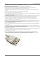
■O
nly a USB storage device with a type A port is compatible. Insert the USB device into the supplied USB gender.
As shown in the picture below, a flat port is type A, compared to a type B port which is rectangular and pole-shaped.
(The examples in the picture are of USB cables. Only a USB client can be used for the projector.)
Type A
Type B
2-5
2. Product specifications
2-6. Supported File Formats
Document, Photo
Item
File Format
Adobe PDF 1.2 ~ 1.7 (pdf)
MS PowerPoint 97 ~ 2007 (ppt, pptx)
Document
MS Excel (xls, xlsx)
MS Word (doc, docx)
Text (txt, asc)
Photo
JPEG, PNG, BMP, GIF. (GIF supports neither Effect nor Rotate.)
Music
MP3, MP2, WAV, WMA, FLAC, APE, HE-AAC, Dolby-AC3
※ BASC does not support audio-only files. Only audio files included in a video file are supported.
Movie, Captions
Item
File Format
Codec
MPEG4
AVI
MP4
ASF
Movie
MPG
RM
FLV
M2TS/TS
VC-1(WMV9)
H.264
MPEG1/2
RV
H.263
WMV7/8
Captions
2-6
Description
1280 x 720 @ 30f
1280 x 720 @ 30f / Level 4.1
1280 x 720 @ 30f
480 x 272 @ 30f
.smi(SAMI)
Microsoft SAMI (Synchronized
Accessible Media Interchange)
.srt(SUBRIP)
SubRip
.sub(SUBVIEWER)
SubViewer 1.0 & 2.0
.ssa(SSA)
Sub Station Alpha v4.00 Script
Format
Content with the GMC option
applied is not supported.
@
!"# $%&'()* +,'(-. /01234 56789:7 !"# &;</01234 =>?
"#
"#
"# !"# AB
AB
FG; HIJKL9MN OPQR&STUVW
XYZ[) &CDE2 "# $%&'()* + \ ]^
_'( `a8@; HIJKL9MN
,'(-./01234 OPQR&STUVWXYZ[) "# $& <bc<
de1fgh FG; HIJKL9MN OPQR&STUVW
XYZ[) Nijk
?lmnopqrst
NstYZuvwx&yz HI&ijdePstpq {|}~0/q /?]ijN&
H?]ijN
}~]/
ij
"#
"#
1f Nk
r123 ¡u¢&£¤¥1f&¦§¨©ª HIu¢/01f /« /0 ¡u¢ stb ¡u¢
"#
"#
{|¬st
®¯«1f 1f:¡& }°±²/
³y ´µ¶r³y·¸¹V·º Y»¼½¾&¿À
stª¼ÄÅ
{|Îs
HIJKÁÂüĿÀ OPWXYZ[) NnÆÇÈk0ÉÊË ³Ì}~¤Í ¡u¢&1f HI/ FGu¢
!"
!"
st ´µ wxYZb}~Ï¡ÐÑ&´µ
¶rÒÓ&}~ÔÕ ?lm³ÌÖ¡&× HI}~/Ø ³Ìy´VÙÚVÙ:\ #$%&'
#
$%&'
()*
()*
ÛÜ
c?z
:
}~Ä`Ý
Þßàbáâ1f Þßàbª& ãä1f c<ª& ãå·æ¼Ä^ç c<&®¼ èé
ê}
ëZ
XìN34Ú
ëZíîâ +,-.
+,-.
+,-.
ÛÜ
c?z
-.3E2V/01234
Þßàbáâ1f Þßàbª& ãä1f
-.àbc<1f èé
! ê}
ëZ
XìN34Ú
ëZíîâ /012-.
/012-.
/012-.
ÛÜ
c?z
@;
ï}~/012{|Vst¬
Þßàbáâ1f Þßàbª& ãä1f
5ð±ñeòó "# $%&' "#
èé
"# ê}
ëZ
XìN34Ú
ëZíîâ $%&' 34
34
¯¥ôõ±ö
÷
øù
øù øù úû
֟
ýþ
ôõ
ÿ
³Ì
ýþ Nôõk óøù
ôõ
øù uvøù ÿ Pôõ/ 6øùÿ
r®¯±ö øù
I
$vMà
12V
HI$Màd
12
12V
HI
d
12
12V
HId
«
«
}°®¼
y
}°®¼
}°®¼
b
¦
!"##$
gÂ
% gÂ
&''
gÂkÑ
÷
!§
"#$e%/& ¶^'(/4)*
12
øù
I
+
+øù,³Ì&-0uv$úû¥./±ö&"#
$ !
uv-0úû¥./±ö&"#$
01ÿ
/>?³Ì 23
/>?³Ì 8
4öY«5&-0
kÑ
kÑ6
34kÑ&"#7-0
kÑ
34kÑ&{|-0
kÑ6
@
/>?³Ì 6
&"#7-0 ÷
!§
34kÑ&{|-0
34kÑ&"#7-0 -. "#$e%/& ¶^'(/4)*
÷
øù
I
ýþ
(
@
89
:8
þ³
@
!§
þ³øù
/>?³Ì
uvøù />?³Ì
"#789uvøù Nþ³Y¦&;<®¼uvøù "#$e%/& ¶^'(/4)*
øù
øù
øù
÷
øù
I
=0v
4=0v
qv
&
4qv
)*
12
4+)*
+)*
12
4)*
,
)*
«,
5
«5
!
@;
4!
¶2
%
4¶2
%
4
ýþ±ö
)
#+*(
!§
4ö
«ýþ±ö
"#$e%/& ¶^'(/4)*
øù
øù
øù
øù
I
-!.
@
(!)!.
-+
)!.
+
uv)!.
(!C>
uv(!C>
C>
uvC>
÷
!§
«¿À.-0
uv(!)!.
"#$e%/& ¶^'(/4)*
56789:
56789:
56789:
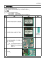
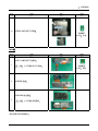
Nc<ª ¥ÆÇÈb ãå NÆÇȪ3 #"
&k÷ ?@$ Hª}%| &@`@;AB
C¼ä¼Ä: «f %« DÂ`«ó&g &« E`@# E ¥ÆÇÈb©F~GH& Ejv HI1f&I ?]J Hª}%|
ã¯jv))¥"$Y`Þßà¥c<&ãå ÷ @;AB 3gÂKL/(#0 % NY«uv`uv
¨ä /¨äP^çjMY&e%/& 4öNOàY&¨ä 0
& zPI÷üQ «
gÂKL÷ü C¼ä]{|¼ $ «*ýþÿ`1* H RS 2 «TU V
$]N}~Y{|¼ HI¼Ä)))))) AB&@;÷ü]/0; ÷ @;÷ü «*)3456U «789 ÷ü QC¼ä¼Äk
a8«789 «ó&gÂDÂ`zP@;
Q«4:;b:
zPf
E
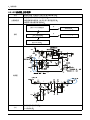
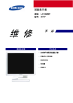
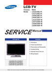
6. Wiring Diagrams
6. Wiring Diagrams
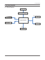
6-1. Wiring Diagrams
R,G,B_LED
⑦
DMD_LED DRIVER
①
AV BOARD
⑤
FAN
②
MAIN BOARD
KEYPAD
③
⑥
FAN
④
SPEAKER
6-1
6. Wiring Diagrams
6-2. Board Connection
KEYPAD
FAN
FAN
SPK
6-2
AV_Board
DMD_LED Driver
RED/GREEN/ BLUE LED
6. Wiring Diagrams
6-3. Pin Specifications
Specification 1
Pin
No.
Description
Pin
No.
Description
1
GND
26
DMD_G4
2
GND
27
LED_TEMP
3
DMD_B1
28
DMD_PCLK
4
DMD_DE
29
P3P3V
5
DMD_B2
30
DMD_G7
6
DMD_HSYNC
31
EMU_DONE
7
DMD_B5
32
DMD_R0
8
DMD_B0
33
WRGOOD
9
DMD_B7
34
DMD_R1
10
DMD_B3
35
SPI_CS
11
DMD_G0
36
DMD_R2
12
DMD_B4
37
SPI_DIN
13
DMD_G2
38
DMD_R3
14
DMD_B6
39
SPI_DOUT
15
DMD_G5
40
P1P8V
16
DMD_G1
41
SPI_CLK
17
DMD_G6
42
EMURESET_N
18
DMD_VSYNC
43
SPI_ON_OFF
19
DMD_R4
44
SYS_PWR
20
SDA_DMD
45
SYS_PWR
21
DMD_R5
46
SYS_PWR
22
CL_DMD
47
SYS_PWR
23
DMD_R6
48
SYS_PWR
24
DMD_G3
49
GND
25
DMD_R7
50
GND
6-3
6. Wiring Diagrams
Specification 2
No.
Descriptions
Wafer Name (Code)
Model Name (Code)
Maker
Remarks
ⓐ
CON-HEADER 14P
Connector-FPC
NEW
-
Yeonho
Electronics
05002HR-14N2
ⓐ'
CON-HEADER 14p
Connector-FPC
NEW
-
Yeonho
Electronics
05002HR-14N2
ⓑ
CON-HEADER 50P
Header 50p
NEW
-
Panasonic
AXT650224
ⓑ'
CON-HEADER 50p
Header 50p
NEW
-
Panasonic
AXT650224
ⓒ
CON-HEADER 50p
Header 50p
NEW
-
Panasonic
AXT650224
ⓒ'
CON-HEADER 50p
DMD Panel
NEW
-
TI
DMD Panel
05002HR-18N2
05002HR-14N2
ⓓ
CON-HEADER 18P
Connector-FPC
NEW
-
Yeonho
Electronics
ⓔ
CON-HEADER 14P
Connector-FPC
NEW
-
Yeonho
Electronics
Specification 3
Pin
No.
Remarks
1
GND
2
P3.3V
3
KEY_PWR
4
KEY_RETURN
5
KEY_RIGHT
6
KEY_LEFT
7
KEY_DOWN
8
KEY_UP
9
KEY_ENTER
10
KEY_TOOLS
LED_GREEN(3V)
11
LED_RED(3V)
LED_LIGHT(3V)
12
LED_RED
13
LED_LIGHT
14
GND
6-4
6. Wiring Diagrams
Specification 4, 5, 6
Pin
No.
Remarks
1
SPKR_OUT_MONO_P
2
GND
3
SPKR_OUT_MONO_R
Pin
No.
Remarks
1
GND
2
ALARM1
3
P5V
Pin
No.
Remarks
1
GND
2
ALARM1
3
P5V
Specification 7
Pin
No.
Remarks
Pin
No.
Remarks
1
BLU_CATHODE
10
RED_CATHODE
2
BLU_CATHODE
11
RED_CATHODE
3
BLU_CATHODE
12
RED_CATHODE
4
BLU_CATHODE
13
LED_ANODE
5
GRN_CATHODE
14
LED_ANODE
6
GRN_CATHODE
15
LED_ANODE
7
GRN_CATHODE
16
LED_ANODE
8
GRN_CATHODE
17
GND
9
RED_CATHODE
18
LED_NTC
6-5
6. Wiring Diagrams
6-4. Connector Functions
Connector
6-6
Functions
CN201
Connects to the keypad. A bad connection will disable the keypad.
CN701
Connects to the AV board. A bad connection will disable the PC, AUDIO and VIDEO inputs.
CN801
Downloads the sub-MICOM and is for technical service purpose only.
CN901
Connects to the speaker. A bad connection will disable the audio.
CN1002
Connects to a fan. A bad connection will disable the fan, causing a fan error.
CN1003
Connects to a fan. A bad connection will disable the fan, causing a fan error.
CN1101
Used for debugging, and is for technical service purpose only.
CN1102
Connects to the DMD board and main board. A bad connection will cause a blank screen.
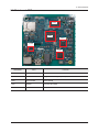
6. Wiring Diagrams
6-5. Main board - TOP
IC501
IC301
IC901
IC103
IC801
REFERNCE
Parts
Functions
IC103
MAX8903
BATTERY CHARGE IC
IC301
TC9101
Supports the audio signal input/ output, scaler and CPU functions.
IC501
K4T1G164QD
DDR2 SDRAM
IC801
TW8816
ANALOG DECODER
IC901
CS42L52
AUDIO DAC & SPEAKER OUT IC
6-7
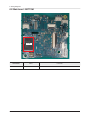
6. Wiring Diagrams
6-6. Main board - BOTTOM
IC103
REFERNCE
IC601
6-8
Parts
K9G8G08U0A
Functions
IC-NAND FLASH