1
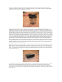
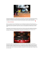
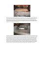
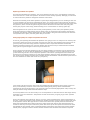
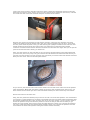
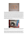
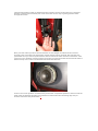
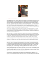
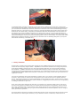
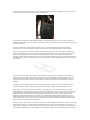
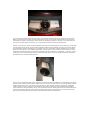
Luke's definitive I.C.E. Install Guide for the GTV
:: Well, it doesn't come any more comprehensive than this. Luke has replaced almost every component of the
internal sound system and added some superb hardware. If you have any questions about any aspect regarding
I.C.E for the GTV, its most probably answered here!
1
2
3
4
5
6
7
- Planning
- The head unit
– Wiring modifications for the head unit
– Fitting a CD Changer
– Replacing the speakers
– Fitting an external amplifier
– Fitting a subwoofer
It seems that when Alfa Romeo built the GTV, they decided that the sound of their glorious engines
were musical enough and neglected to fit a quality stereo. For those of us who own a GTV V6, the
charms of that wonderful, warbling V6 are evident, but sometimes we do want to listen to some
music, and let’s face it, the standard fit equipment is just appalling. There is only one thing to do –
change it.
What I have tried to do here is to create a step-by-step guide on how to install a new sound system
into your GTV. I have built it up over a number of chapters, each one getting more and more highend. You can read on as far as you like, depending on your budget and the results you want to
achieve from upgrading your in-car entertainment (ICE) system.
1 – Planning
Before you do anything, you need to figure out how far you are going to take things. There are two
key elements to consider here. The first is budget, think about how much you really want to spend on
a project like this and stick to it. If you like, you can stagger your investment, slowly adding
components as you go along, but if you do, make sure that the components you fit now will be
compatible with the ones you are planning to fit in the future. Secondly, think about how important
high-quality sounds are to you, for example, think about the kind of stereo you have at home. If, like
me, it is very important then you might go the whole way. However, this is bound to be too much for
most people, work out what you want to do and match it to your budget.
There are four key elements to any in car entertainment system. First of all the head unit. This is the
heart of your system, so choose very carefully and work out if you want to add a matching CDchanger. Secondly, amplification – Do you want to use the amplifier in your new head unit or do you
want a separate power amplifier, perhaps even multiple power amplifiers? Thirdly, the speakers.
These are critical, the speakers you choose will dictate the way the sound is delivered. If you are
adding off-board amplifiers then you’ll need to ensure that your new speakers will be able to cope
with the power you are going to be throwing at them. Lastly, a sub-woofer. This is really important if
you want to accurately reproduce low frequencies. As the speakers you will be able to fit to your GTV
won’t realistically be bigger than 6.5” midrange drive units, any frequency lower than 100Hz or so
will be difficult to reproduce. A subwoofer is the only way to deal with this issue, but they are
expensive and they take up a lot of boot space.
Once you have considered all the elements carefully I suggest you try to listen to components that fit
into your budget, choose very carefully and remember to budget for cables and connectors, as well as
any custom made parts, like a box for the subwoofer for example. y
2 - The head unit
There is no getting away from the fact that the standard fit Clarion unit you have is completely
rubbish. The only good thing about it is the Alfa Romeo logo on the facia, otherwise it is absolutely
worthless, do your ears a favour and get rid of it!
The head unit is the heart of your system and is critical to the whole installation. Choosing a
replacement head unit is not easy, there is a lot out there. You should already have worked out your
budget, try to stick to it, but give yourself a little leeway, say £50 or so. First of all, you don’t want
something that’s going to look out of place, so green illumination is a must. Most units these days can
switch between amber and green illumination, but remember to check for this, a mass of glowing red
buttons will look really out of place at night in your GTV. Secondly, think about the features you want,
CD player, MP3 playback, Minidisk capability etc. Also, consider your project as a whole. For example,
if you are adding external amplifiers and a sub you will need at least three 4V pre-amp outputs (front,
rear and sub). On the other hand, if you are just changing the head unit and the speakers, then you
will want a unit with a high quality built-in amplifier. Lastly, only buy from the best manufacturers Always ask for advice on this one, either in the forum on this website or at your local ICE dealer. I
chose an Alpine head unit, but this does not mean they are necessarily the best, my advice is to stick
to Alpine, Blaupunkt, Kenwood or Rockford Fosgate. There are some other gems out there, certainly
Pioneer and Sony do come up with some killer head units, however they seem less consistent than
the other brands I’ve mentioned here.
Replacing the head unit is quite simple, in fact you don’t even need to disconnect the battery. I have a
Phase I interior and the standard Clarion head unit, I bought my car new and it came with two little
metal tools for removing the head unit. These are inserted into the two holes on the top of the stereo
facia, one either side of the unit. Insert the tools and then pull them out towards you, the head unit
should simply slide out.
On the back of the unit you’ll find some connectors, unclip these and pull out the aerial plug. Put the
stereo to one side and look back into the slot where it once sat. You should see a metal “cage”
protruding into the empty hole from the edges of the slot. This is held in by pushing out metal cutouts on the cage, these cut-outs lodge themselves behind the dashboard so the cage (and the stereo)
won’t fall out.
Work your way around the cage with a small screwdriver and bend the cut-outs back in, once you
have all of them bent back you should be able to remove the cage by simply sliding it out. Keep the
original head unit and it’s cage in a safe place as you might want to re-install it when you come to sell
your car.
Fitting a new head unit is simply the reversal of this procedure, but before you do this you will want
to install a surround plate into the stereo aperture. This is an inexpensive item and it is available at
your local Alfa Romeo dealer. I believe they are all black, so if you have a phase II interior you will
want to get it sprayed silver to match the rest of your interior.
Make sure you fit this item now, if you want to fit it at a later date you will have to remove the stereo
again! It is worth the hassle though, for a little piece of plastic, it makes a huge difference to the
overall look of the installed head unit.
This surround does not affix itself to the aperture, it relies on the new stereo cage to hold itself in
place. Whilst this works, it will rattle. When you fit this piece take the time to smear the back of it
with silicon sealant to ensure that it won’t rattle once you have your new head unit installed.
*****
At this point you may want to jump ahead in the guide. If you are planning on fitting a CD changer, go
to chapter 4, if you are fitting any external amplifiers or sub woofer, go to chapter 6 & 7, follow the
instructions there first and then come back to this chapter. However, if you are just changing the
head unit, or the head unit and the speakers, please read on.
*****
Alfa Romeo, in fact all cars manufactured by the FIAT Group, have one distinct advantage, the stereo
connectors used are industry standard ISO connectors. This means that you will not need a special
adaptor to fit your new stereo, the sockets behind the stereo will fit the plugs on your new stereo,
regardless of manufacturer. However, I would recommend using an ISO extension adaptor as it
makes it much easier to fit your new head unit. These are available from any good ICE supplier for
about £10.
Open up your new stereo box and locate your new “cage”. Fit this by inserting it into the slot and
pushing out the metal cut-outs, work your way around the cage until you get a nice tight fit. Then fit
the ISO extender if you have one. Go back to your new stereo box and dig out the main unit, don’t
worry about the stereo face at this point. On the back of your new stereo you will find a socket for the
aerial and two ISO connectors, dig out the cables from behind the stereo and simply connect
everything up – Easy. Now slide the unit into the cage, as you push it back it should “click” into
position.
That’s it, your new head unit is fitted. Dig out the face and clip it on, you should now be able to start
playing with your new stereo.y
3 – Wiring modifications for the head unit
This chapter is for those of us who want to modify the standard wiring, if you don’t feel confident
with this then please skip this chapter. I’m going to cover three points here:
• Getting your stereo to turn on and off with the ignition
• Automatic stereo illumination
• High quality earthing and +12V power supply
Getting your stereo to turn on and off with the ignition
Have you ever noticed that your stereo doesn’t automatically turn off when you switch off you
ignition? Annoying isn’t it? It’s actually an error in the wiring loom, I believe some cars actually don’t
suffer from this fault, so I put it down to manufacturing problems – No surprise there then! Anyway,
this can be easily fixed without too much effort.
First of all, locate the two ISO connectors that plug into the back of your stereo. I suggest that you
make sure your stereo is removed and that you take off the panels that sit either side of the central
tunnel as it feeds back into the footwell. These are held in place by two screws and a clip at the
furthest part of the unit, near the end of the footwell. Now you should have a pretty clear view of the
cables behind the stereo.
Disconnect the battery. Now go back inside the car and locate the large white connector the connects
up to the cables that run through the centre console past the gear stick, towards the handbrake and
the buttons between the two seats. disconnect that as well.
Going back to the ISO connectors, in particular the white connector, you will see that it has a number
of cables going into it from behind the dashboard, each cable is for a different function. One of these
is supposed to be the switched +12V, this is only supposed to come on when the ignition is turned on,
however it doesn’t, it’s always on. This is the RED cable.
Trace this cable back, unwrapping the insulating tape on the cable cluster as needed and cut this
cable cleanly about three inches away from the connector. Seal the end of the cable coming from
behind the dashboard with electrical tape and strip the other end (the one coming from the ISO
connector) so you can fit it to a standard electrical connector. Now take a length of electrical cable.
For this purpose I took a 1m length of standard, UK-Spec 13A power cable and stripped it back, giving
me three 1m lengths of thin cable (blue brown and green). Take a standard electrical connector
(screwbox or crimp connector) and connect this length of cable to the red cable coming from the ISO
connector (the one that you stripped the end off earlier).
Now go back to the large white connector that you unplugged earlier, you’ll see a whole load of
cables going into it. One of these will be a true switched +12V. In my car this is a red cable, but all
GTVs are different, so the chances are it'll be a different colour on your car. You can easily find out
which one of these cables is a switched +12V by checking the connectors one by one with a digital
multimeter. This cable is used to turn things on like the cigarette lighter or the sunroof switch (if
fitted) on when you turn on the ignition. Trace this cable back as far as you can – Unwrapping the
insulating tape as before – cut it cleanly about three inches before it disappears into the dashboard.
Strip both sides of the cut cable this time, as if you were going to fix the wire you just cut. Use a
standard electrical connector as before and connect it to one of the stripped ends. Now take the end
of the cable you just attached to the ISO connector, cut this cable to the length required to reach the
cable you are now working on. Strip the end of this cable. You should now have a cable connector
connected to a cable on one side and nothing on the other. You should also have two unconnected
cables with stripped ends. Twist the ends of the two unconnected cables together and connect them
up to the empty side of the connector.
That’s the difficult bit out of the way, now tape everything up with electrical insulation tape and wrap
it all up again using the standard Alfa insulating tape that you unwound before, seal the ends with
standard electrical tape. You will now find that when you refit your stereo it will turn on and off with
the ignition.
Automatic stereo illumination
Your stereo lights are supposed to dim when you turn on your headlights. For some reason this
feature never worked in my car, this is obviously down to the same manufacturing problems as the
ignition on/off issue.
You can fix this by following exactly the same procedure as I have outlined for fixing the ignition
on/off problem above. However, you will need to join the 'yellow/green' cable from the ISO
connector to a cable that switches to +12V when you turn the headlights on. Again, use a digital
multimeter to locate the appropriate cable to connect to.
High Quality Earthing and +12V power supply
At this point I think it’s safe to assume that the quality of the standard wiring behind the stereo
leaves a lot to be desired, that doesn’t inspire confidence in the quality of the permanent +12V power
or the earth connectors. If you are serious about your ICE installation then whatever you do, do not
use the standard connectors. First of all, take the earth cable directly from the back of the head unit
and earth it to the metal frame underneath the stereo slot (as illustrated).
You will need to remove the centre console around the gear stick area to gain access to this metal
frame, but it is worth it as the bolt is perfect for connecting a standard circular electrical connector
and this point gave me an ideal measured earth reading.
As for the +12V connector, you will need to run a cable directly from the battery to the head unit to
get a perfect connection. Please follow the instructions in Chapter 4 describing how to lay cables
through the interior in order to lay this cable. Use a good quality 4 gauge cable if you can, connect it
to the standard positive battery terminal connector, then run the cable through to somewhere near
the stereo socket. I have taken mine along the side of the centre tunnel to avoid electrical
interference (or cross-talk) with the speaker and phono cables. I suggest terminating the cable with
a simple fuse box. I have attached a small fuse box to the metal frame near the earth point using
silicon sealant.
Connect the permanent +12V cable directly from the back of the head unit to this fuse box to ensure
the absolute best quality +12V power supply. The head unit is a critical component, if it does not have
a quality +12V supply or earth connection it will never sound it’s best. If you are taking this
installation seriously then I cannot stress how important this relatively simple modification is. y
4 – Fitting a CD Changer
Most of you will want to fit a CD Changer if you are replacing the head unit. These little boxes are
great, allowing you to stick a stack of CDs in the car and switch between them at will. Remember that
CD Changers have to be matched to head units, there are lots of different standards and connectors,
even from the same manufacturer. Make sure you get a CD changer that will work with your head
unit.
The glovebox is pretty small in the GTV and there is virtually no space under the seats, so the only
logical place to fit a CD changer is in the boot. There are two great places for fitting these devices. If
you have a phase I car, I suggest fitting the unit to the top of the boot, close to the edge of the
opening. You can easily run the cable back through the top of the bootlining.
If you have a phase II car then you have a ready-made spot for a CD-Changer, the “cubby-hole”
above the fuel tank to the left of the boot. If you are going to use this spot then make sure you get a
small piece of MDF cut to mount the unit onto – DO NOT screw directly to the metal of the car body,
that’s the fuel tank, remember? This is quite easy anyway, take out the bootlining at the top part of
the rear of the boot. This comes out very easily by just removing some grip studs and thumb screws.
You will see the “shelf” on the left where the little “cubby-hole” sits. Get some MDF cut roughly to the
size of the shelf.
Now take that piece of MDF and match it up to the bottom of the “cubby-hole” on the boot lining and
cut it down to size. Stick the MDF to the boot lining using some strong double sided tape. Take the CD
player and mount it in place, screwing through the bootlining into the MDF. Now stick some 3M
adhesive fastener tape (that really sticky foam tape) and put strips of it on the bottom of the MDF.
Cut a small hole in the back of the “cubby-hole” and stick the connector from the CD changer through
it. Refit the bootlining remembering to stick down the MDF to the shelf above the fuel tank. Your CD
Changer is now fitted, but not connected.
In order to connect the CD Changer to the head unit you will need to connect the two together using a
cable. The only way to do this is by removing some interior parts. First of all, you will have to remove
the rear seats. The rear seats are made up of just two parts, the bottom part and the back part. The
bottom part must be removed first. There are two bolts holding it in place, look at where the seat
joins up with the footwell, in the middle of each seat (either side) you will find a bolt, undo both of
these. Now pull the seat forward to release it from the connectors you just unbolted, lift it up, and
then out, to remove. The back part is connected by a further two bolts located at the bottom of the
seatbacks, these are immediately visible when you remove the bottom part of the seats. Undo these
bolts as well. To remove the seatbacks, push them up and then pull them towards you, they should
just come out in your hands. There will be a layer of sound insulating material behind the seatbacks,
remove this and you’ll be able to see right through to the back of the “cubby-hole” in the boot.
If you have a phase II car and you followed the above instructions you should now be able to see the
connector to your CD-Changer, take your CD-Changer cable and connect it. If you have a Phase I car
you should ensure that your cable is connected to the CD-Changer and is routed through to this area.
Now take the CD-Changer cable and carefully run it down towards the bottom of the door opening,
you should ideally route it through behind the rear side panel and hold it in place with duct tape. Now
move down to the door opening. There is a black plastic panel running along the bottom of the door
opening next to the door seal, remove this panel. It simply pulls up and then pivots out from the front
– Take care with this. Once removed you will see the wiring channels underneath. Continue to run the
cable through these channels towards the front of the car.
Now all you have to do is to get the cable through to behind the head unit. If you pull at the carpet it
should give, allowing you to route the cable underneath it. Work from the cable channel, up around
the top of the footwell and right the way through to the back of the stereo. You will need to remove
the panel that runs alongside the centre console next to the stereo in order to get the cable all the
way through, this is attached using two Philips-head screws and a small clip towards the back of the
footwell. Once you have routed the cable all the way through, connect it up to the back of the head
unit and refit everything. y
5 – Replacing the speakers
Speakers are critical to the overall sound of your finished installation, choose them well and try to get
units that suit your listening tastes. Work out what size speakers you are going to install and what
amplifier you are going to use. This, along with your budget will give you the basic guidelines you’ll
need to start short-listing your speaker choice. Try to stick to the best brands, when it comes to
speakers that essentially means Focal, Infinity, MB Quart and Phoenix.
This chapter is split into two sections:
• Replacing standard size speakers
• Fitting high-quality 6.5 component speakers all-round
Replacing standard size speakers
The GTV has essentially six speakers. Two 0.75” tweeters and two 5”x7” oval speakers in the front
doors and two 6.5” round rear speakers. All of these can be directly replaced, although you will need
to remove the door panels to change the tweeters in the doors.
Removal and refitting of the main speakers is quite simple. Regardless if you are working on the rear
or front speakers, the process is essentially the same. You need to remove the grille first. Do this by
inserting a large flat-head screwdriver between the grille and the interior panel at the side, then push
the grille out, move around the grille doing the same at the bottom and the other side, the grille
should just pop out at this stage, without having to use a screwdriver for the top grille-clip.
Once the grilles are off you’ll see four screws (front speakers) or four nuts (rear speakers). Undo
these, disconnect the cables (taking note of which colour is connected to the positive and negative
terminals) and directly replace them with your new speakers using the same screws/nuts. Once the
new speakers are in place, refit the grilles and you’re done.
Fitting high-quality 6.5 component speakers all-round
Of course, just replacing the standard fit speakers isn’t going to cut it for everyone. For starters, the
5x7 ovals in the doors are far from ideal, even the very best 5x7 oval speakers aren’t going to be as
good as quality round mid range/tweeter component units. Couple that with the fact that the
standard speaker mounts do not 'seal' the speaker into the door and you realise that the standard
setup just isn't good enough. So what can you do about it?
First of all get some decent speakers for the rear. Rear speakers are nowhere near as important as
front speakers, so you can just fit standard 6.5" speakers. However, if you're really serious you can
go the whole hog and fit a set of component speakers. This will be a package that will contain two
tweeters, two crossovers and two 6.5” mid-range speakers. Fitting is pretty straightforward, fit the
6.5” mids into the standard speaker slots and then mount the tweeters onto the interior panel next to
the rear seatbacks on either side of the car (see photo).
You’ll need to fit the crossover units in the boot behind the top bootlining, there’s bags of space in
there, I mounted my crossover units on the shelf running along the top of the bulkhead that
separates the boot from the interior. The crossover units are normally light plastic units, so they can
easily be affixed using double-sided 3M adhesive tape.
The front speakers are a lot more tricky. 6.5” round speakers are the ideal size for mid-range drivers,
especially if you fit a subwoofer. The question is how on earth are you going to get a 6.5” speaker
into a 5x7 slot?
First of all, take the door panels off. This is, of course, easier said than done. Start at the bottom of
the door, remove the speaker grille and then the standard speaker. Unscrew the two allen bolts next
to the speaker mounts. Now pop the two round covers off the door pocket panel and unscrew the
allen bolts underneath them. Remove the door pocket panel and unscrew the allen bolts that are
located on the very lower part of the door panel. Now move up the door panel and remove the allen
bolt behind the door handle. Take a small flat-headed screwdriver and remove the electric window
switch panel, unplug the electric window switch and then undo the allen bolt inside the exposed
cavity. Now move around to the side of the door where it meets the dashboard and remove the two
allen bolts on the door panel. Finally, move up to the separate piece behind the door mirror, undo the
two small allen bolt on the side and slide the piece off towards the window.
Now the door panel is unscrewed you will need to remove it, take great care with this, the panel
needs to be lifted up from the bottom and it will “pop” off the lugs that hold it in place – Don’t drop
the door panel! Once the panel is free, you will need to grab a philips screwdriver and undo the door
handle working from inside the door panel. Then you simply have to disconnect the speaker
connector from the tweeter and the electrical connector for the lower-door light. Now you can put the
panel to one side and take a break, you deserve it!
Okay, now the panel is off, the first thing to do is to remove the old tweeters and replace them with
your new ones, this is very easy to do, just unscrew the old tweeters and follow the instructions you
got with your new tweeters in order to fit the new ones. Now you need to take some drastic measures
with your door cards. Take a look at the photo below:
As you can see, the section in the lower corner needs to be cut back to the same level as the speaker
grille clip holders. Whilst this does mean cutting off one door card mounting point, don't worry, you
don't need it! It won't make your door card loose when refitted, nor will it create any extrs rattles.
Now do the same for the other door.
Okay, the door panels are finished, all you have to do now is to mount the speakers. You will find that
your new 6.5” round speakers are too deep to fit straight onto the door panel without interfering with
the window mechanism, this is why you have just cut up your door panels - You are going to need to
mount the speakers away from the door panel. In order to do this you will need to make (or get
made) two rings of MDF. These rings must be the right diameter to allow you to mount the speakers
into, and, at the same time, they must be deep enough to allow you to mount the speakers onto the
door without the back of the speaker fouling the electric window assembly.
Make sure the speakers don’t foul the window mechanism, test this by winding the window up and
down whilst the speakers are held in place. Once you are happy with the MDF rings, mark out all the
mounting points for the speaker onto it. Now peel away the door lining, place the ring in place on the
door and line it up, marking out the points where the door panel connects to the door behind the
speaker grille. Secondly, feel around inside the door and locate at least two areas on the lower part of
the ring where you can mount it to the door and the same in at least two places on the upper part of
the ring. This is not easy, as there is a lot of stuff mounted inside the door. Mark out these points out
on the ring and move it to a workbench. First of all, you will need to drill holes for the mounting
points in order to mount it to the door. Once you have this done, line the ring up again and scribe the
mounting points onto the door, put the ring to one side and drill the mounting holes in the door. Now
fold back the door lining and mount the ring using some quite long self-tapping screws. Mount the
speaker into the ring in order to do this, screw through the speaker mounting holes and the holes you
recently drilled in the MDF rings untill you hit the metal of the inner door skin, then just screw
everything tight. Don't forget to connect up your speaker cables and make sure the whole assembly
lines up properly by temporarily placing the door card over the mounted speaker ring. Make sure the
MDF doesn’t rub against any part of the door panel or it will creak when it’s all refitted properly. Once
installed it should look something like this:
Finally, you will need to fit the crossover units. The best place for these is on the door, mounted just
behind the gap that sits between the grab handle and the door pocket on the door panel. You can see
exactly where I mounted my crossover units on the picture above (it's the red box with the blue
cables connected to it).
Mount this on the same way as you mounted the speaker rings, by drilling small holes and using self
tapping screws. Finally, you should replace the speaker cables with something more substantial.
There are no crossover units fitted as standard, so just trace the two sets of speaker cables back
inside the door towards the point where the cable run enters the inner door cavity. Cut one of the two
cable pairs back and tape it up using electrical tape. Cut the other cable pair back, but leave enough
cable exposed to allow you to connect up some decent cable to it. There is no point running quality
cable back through the cable run between the door and the car body as the cable run is socketed.
However, I believe that somebody else on the forum has found a way of getting speaker cables
through this socket.
Wire your new cable up to the crossover and then run new lengths of cable from the crossover
through to the areas where the mid speaker and the tweeter will be mounted. Now refit the door
panel. Make sure you connect up the tweeter cable as well as the other electrical connections. Take
great care not to bend the rod that connects to the door lug and ensure that the door handle cable is
fitted correctly in it’s socket. The finished item should look like this:
That’s it! Your front speakers are fitted, now you have 6.5” component speakers in the front and the
back of the car! Replace the grilles (you will have to remove the lower mounting clip) and you
wouldn’t even know they were there. y
6 – Fitting an external amplifier
If you really want to get the best sound possible from your car audio you will need to add an external
power amplifier. Your head unit has a built-in power amplifier, but given the size of the head unit it is
physically impossible to squeeze a high quality power amplifier in there. So, even though the power
amplifiers in head units are getting better all the time, they don’t even begin to compare to the
quality of a dedicated off-board power amplifier. Any decent head unit will have at least one 4V preamp output, with higher quality units offering two or three dedicated outputs. Try to get a head unit
with three outputs, each output will be dedicated for a particular signal, in this case they will be the
front speakers, the rear speakers and the sub-woofer. A head unit with three 4V pre-amp outputs will
allow you to control everything from the head unit, so you can adjust the sound levels, crossover
frequency and subwoofer level all from the drivers seat. Of course you could use a single amplifier for
everything, but that is a compromise that I recommend you avoid.
External power amplifiers come in different flavours, typically you’ll find single channel, 2 channel
and 4 channel units. A single channel amplifier is typically designed to be used with a sub woofer. A
2-channel amplifier will power just two speakers, so you could use two of them, one for the front
speakers and one for the rear speakers. However, it is easier to opt for a 4 channel amplifier that will
power all four speakers inside the car.
Again, try to listen to the amplifier before you buy and take your time, choose very carefully. At the
moment the biggest names in car amplifiers are Rockford-Fosgate and JL Audio. There are some other
really great amplifiers out there from other manufacturers, so listen to as many as you can. JL Audio
are universally acknowledged as the best but they are not cheap. Stick to Rockford-Fosgate amps if
you want to stay in budget, they sound fantastic and they represent excellent value for money.
The ultimate configuration is a 4-channel amplifier for the internal speakers and a separate single
channel amplifier connected to a subwoofer. If you are going to add a subwoofer (details in chapter
7) then you should plan ahead at this stage and ensure that you have a suitable amplifier ready to
drive it.
Make sure that the amplifier or amplifiers you purchase will work well with the speakers you have
fitted. First of all, it is important to understand how the power handling relates to the power output
of your amplifier. Your speakers will be rated with a maximum power input, something like 100W or
200W. That is the maximum peak power you can drive into the speaker without damaging it.
Meanwhile your amplifier will have a power rating, something like 50W or 100W per channel. Now
this is the RMS value, not the peak value – What’s the difference? Okay, the peak power is the
absolute peak power reached over a given listening period whilst the RMS value is the “Root-MeanSquare” value, essentially the average power output over a given listening period. Without getting
into to too much depth on this issue I always suggest that you use one simple rule of thumb, take the
RMS output value (or Watts per channel value) of your amplifier and double it to work out the peak
value required for you speakers. So if your amp outputs 50W per channel, then ensure that your
speakers will handle 100W max input. Okay, it’s not very scientific, but it’s easy to remember and it’s
a good enough rule to ensure that you won’t blow your speakers.
Furthermore, you should check that the resistance of your speakers match your amplifier
configuration. You may well find that your amplifier can be switched between 2 Ohms or 4 Ohms.
Typically your internal speakers will be 4 Ohm units, however, just to make things really complicated,
subwoofers tend to be rated at 2 Ohms (so they can be used in pairs). Read the manual supplied with
your speakers and amplifiers then adjust your amplifier’s settings to match your speaker ratings.
Now you’ll have to figure out where you are going to mount the amplifier. If it’s a small amplifier you
might just be able to fit it under one of the front seats, or even find some space behind the top part of
the bootlining above the fuel tank. If your amplifier is bigger then you’ll have no choice but to put it
in the boot. One thing to remember here is that you should never affix your power amplifiers directly
to the sheet metal of your car. Always make a mounting plate out of MDF, affix that to the car body
and then mount the amplifier onto the MDF mounting plate. There are some obvious places for
mounting an amplifier, such as on the back wall of the boot (with the spare tyre removed) or in the
phase II boot “cubby hole” (although you’ll have to mount your CD-Player elsewhere). Find a good
spot and get the MDF mounting plate cut to size. Attach the MDF to the car body using adhesive tape
or screws behind the boot lining and screw on the amplifier through the bootlining onto the MDF.
Before you mount the amplifier you will need to lay down and connect a number of cables. First of all,
find a good earth point in the boot, I used one of the bolts holding the boot locking mechanism in
place for this. Secondly, take another lead directly from the positive terminal of the battery to get a
clean +12V power supply. Use the highest gauge cables that your amplifier’s connectors will cope
with for these two connections. Secondly, you will need to run phono cables from the 4V pre-amp
outputs on the back of your head unit back to the amplifier. Follow the instructions detailed in
Chapter 4 for laying the CD changer cable, but run the phono cables down along the other side of the
car to avoid any unwanted interference. You will also need to hook up a remote switched power cable
through to the head unit, this just acts as a switch, telling the amps to turn on when the head unit is
switched on, you don’t need to use a very high quality cable for this function. Again, try to isolate this
cable as much as possible.
Lastly, you will need to run speaker cables from the amplifier through to your speakers (or crossovers
if you are using component speakers). This is pretty straightforward for the rear speakers, however,
you will need to run new cables through to the point where the cable run starts between the main
bodyshell and the front doors. As I mentioned before, this is socketed so you cannot run cables all the
way to the door speakers (or crossovers).
You’ll find that if you are using an improved power connection for the head unit, A CD-Changer and an
amplifier you will have a lot of cables running through to the front of the car, you need to separate
these cables as much as possible to avoid unwanted interference. In my car I am running the speaker
cables down through the left of the car and along behind the footwells, the head unit power, amplifier
remote power and CD changer cables are run along either side of the central tunnel (you will need to
remove the seats to get access to this area underneath the carpet (see photo). Whilst the phono
cables down through the right of the car, I think this is the best solution as it isolates all the cables as
much as possible.
I recommend that you take a weekend to do all the interior cabling. First of all, take out the front
seats (make sure the battery is disconnected when you do this and that it remains disconnected until
you reconnect the seatbelt pre-tensioner connectors under the seat or the dreaded airbag warning
light will come on). The seats are easy to remove, just undo the allen bolts on the seat runners (two
at the front, two at the back), unclip the pre-tensioner cable lock and pull them out. Then clear out
the interior as much as possible and get all your cables run in one go – You can give the interior a
good clean while you are at it too. This way you can connect up all the cables at the back of the head
unit, finish fitting the head unit and put everything back so the car is driveable. You will be left with a
whole load of cables in the boot, but at least you can then work on finishing that part in your spare
time whilst still having a driveable car. y
7 – Fitting a subwoofer
A subwoofer is simply a big speaker that reproduces low audible frequencies. The human ear hears
sounds in the frequency range of 20Hz – 20,000Hz. Your tweeters will take care of high frequencies
from about 2,500Hz upwards and your mid range speakers will take care of frequencies between
about 100Hz – 2,500Hz. This takes care of most of the frequency range we can hear, but you’ll be
surprised just how important those low frequencies are. A subwoofer will take care of the frequencies
roughly between 20Hz-100Hz. Obviously this is essential if you really want to hear your music as it is
supposed to sound.
You can buy subwoofer drive units (speakers) on their own or you can buy a sub complete with an
enclosure. A sub needs an enclosure to work properly due to the amount of air a speaker that big
moves. The biggest problem you’ll have with fitting a sub is finding the space. For this reason I opted
to buy a drive unit and build my own custom enclosure, I suggest you do the same if you are planning
on fitting a subwoofer to your car.
A 10” sub is more than sufficient for the GTV, it’s a small car so it doesn’t need to move a lot of air.
The best sub speakers available today are made by Rockford Fosgate and Lightning. Accept nothing
else. Also, remember that you will need an extra single channel (or two channel for dual voice-coil
subs) amplifier to drive the sub, try to get one that matches the 4-channel amplifier you are using to
drive your interior speakers.
The most obvious solution is to build a box that fits into the corner of the boot, this is fine and I used
this solution for a while myself. However, as you will have to have a small box, it will need to be
sealed, it will work well, but not as well as a larger, ported enclosure. Regardless, it doesn’t take up
too much space, so it could prove ideal for most people.
If you have no experience with speaker design I recommend that you get your local ICE dealer to
build this enclosure for you, they will also be able to finish it in carpet for you so it blends in well with
the rest of the boot.
If you are really serious about the sub, then read on. I have designed and fitted a ported sub
enclosure to my car with fantastic results, if you want to do the same then here’s how I did it:
First of all, I wanted a solution that would accommodate the sub as well as provide somewhere to
mount the amplifiers, my 4 channel amp is quite big, so finding a place to put it has always been an
issue. The first thing I did was to remove the spare wheel in order to free up as much space as
possible. Once I had the spare wheel out, the natural slope of the boot gave me an idea. I decided to
use that natural slope to accommodate the sub enclosure, I started sketching ideas and came up with
this design:
The idea is that the bulk of the volume required for the sub enclosure is spread out through the
natural slope of the boot floor, this can be topped off with a flat shelf, effectively giving a new flat
bottom to the boot. This would be an ideal spot to mount the amplifiers and, although the sub
speaker will be exposed, it can be covered with a grille so the boot can still be used for occasional
luggage.
On paper the concept looked good, but I thought it might be a bit tricky to build. Luckily I know a
friendly carpenter and he really helped out, showing me the easiest and quickest way to do it.
First of all, you need to make some templates, use some cheap, thin fibreboard for this, cut this
approximately to size and then mark it out accurately and trim it down in-situ until you get accurate
templates. Start off with the bottom, then build up the sides. This stuff is really easy to cut, but a
Black and Decker Workmate and a decent jigsaw make the job even easier. Once you have the
templates, make the bottom part of the box up in 15mm MDF (medium density fibreboard), then
make up the sides using the same material and get them screwed together. Place this in the boot to
double check that it fits. Aim to make sure that the top of the box will line up with the natural shelf
either side of the curved bottom of the boot.
Now you need to create a top for this box, this top part will be bigger than the size of the box you just
made, take it right out over the natural shelf either side of the curved boot bottom, so you end up
with a flat floor right up to the full vertical sides of the boot. Again, use some thin fibreboard to make
a template and then make up the final piece in 15mm MDF. Make sure that the subwoofer will fit into
the box without the back of the speaker touching the bottom of the box, try to raise it as much as
possible. You can do this easily by cutting a hole for the speaker and trimming it with a 15mm MDF
“ring”, effectively raising the sub by 15mm. Now try fitting everything in place and make sure it all
fits properly. Then take everything out again and fix it all together using wood glue and wood screws
to make sure that it is air-tight. You should end up with a box that looks something like this:
Of course you will need to get the sub fitted. Get yourself a high-quality speaker terminal connector
that can be flush mounted. Now fill the enclosure with some wadding (make sure it’s fireproof) and
ideally cut a port into the top of the box. Mark out the positions of the amplifier (or amplifiers) and
the position you want to mount the speaker terminal first. Find the optimum position for all the
equipment, so that it all fits and looks as good as possible – Remember that the amplifiers and the
subwoofer will be visible when the whole installation is finished. Cut a hole for the speaker terminal
point and wire it through to the sub. Now screw them into place and use a port finisher on the port
hole. You should now have a finished box that looks something like this:
Right, that’s the box finished. Now you need to get it fitted. First of all, work out where all your
cables need to run in order to terminate at the right place near your amplifier or amplifiers. Run the
cables down behind the bootlining and cut small holes to feed the cables through near their
termination points, but below the point that the top of the sub box will reach. Use some wadding to
line the bottom of the boot in order to get a nice tight fit and then drop in the box. You will find that
there is a method to getting the box into the boot, but it should fit in there without too much bother.
Once the box is in place, fit your amplifier or amplifiers and wire everything up. You can now test
your system as essentially everything is fitted, you only have the finishing to do now. You’ll probably
want to spend some time setting up the amplifier gain levels, crossover positions and so on at this
point in order to ensure that everything is set to it’s optimum levels. Your fitted sub box will now look
something like this:
You will want to finish things off now. Once all the electronics are all set up properly, mount some
MDF or wood blocks onto the sub enclosure that come up to the same height as the tops of the two
intruding sub-frame/rear bumper mount points at the back of the boot. In fact, if you find that your
sub box is moving about in the boot, you can mount the box to these two metal parts.
Finally, you’ll have to make one last template that will cover the whole top of the sub box, going right
out the edges of the boot. Use the same method as before and remember to mark out exactly where
the subwoofer and the amplifiers are mounted. Once you are happy with the template you can then
make up a final piece out of 100mm thick MDF. You will have to cut a hole the same diameter of the
subwoofer directly above the sub position and holes for the amplifier or amplifiers , so the top of the
amplifier(s) can fit through the hole. You should find that the top of the amps should line up pretty
well with the top of this finishing panel.
Once you are happy with this panel, mark out screw holes above the MDF (or wood) blocks you fitted
earlier and screw the panel in place. Obviously you can leave it like this, but you will probably want to
finish it off properly. You can use any type of trim you like, diamond pattern aluminium, industrial
rubber finish or carpet, whatever you think will look best. I opted for carpet and had the finishing
panel trimmed a local upholstery shop. Once trimmed I fitted a metal grille above the subwoofer hole
(purchased at Radio Shack), I also used stainless steel screws with washers to re-fit the panel and
give a good looking and practical finish. The finished product looks like this:
That’s it – You now have a top quality ICE installation and you did it all yourself. Pat yourself on the
back, crack open a few beers and sit in the garage listening to your new stereo for a couple of hours!
I hope you’ve found this guide useful, if you have found an easier way to do anything I have
described here or have found a solution to any problems I might have highlighted then please feel
free to contact me using the forum on this website.
And finally - Good luck with your ICE install! y
456