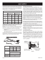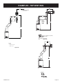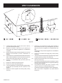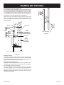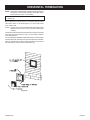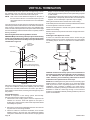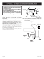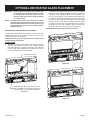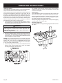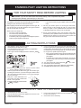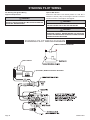
1
INSTALLATION INSTRUCTIONS
AND OWNER’S MANUAL
INSTALLER: Leave this manual with the appliance.
CONSUMER: Retain this manual for future reference.
Direct vent
Gas Fireplace
WARNING: If not installed, operated and maintained
in accordance with the manufacturer’s instructions,
this product could expose you to substances in fuel
or from fuel combustion which can cause death or
serious illness.
Model series:
GAS-FIRED
WARNING
FIRE OR EXPLOSION HAZARD
Failure to follow safety warnings exactly
could result in serious injury, death or
property damage.
— Do not store or use gasoline or other flammable vapors and liquids in the vicinity of
this or any other appliance.
— WHAT TO DO IF YOU SMELL GAS
• Do not try to light any appliance.
• Do not touch any electrical switch; do
not use any phone in your building.
• Leave the building immediately.
• Immediately call your gas supplier
from a neighbor’s phone. Follow the
gas supplier’s instructions.
• If you cannot reach your gas supplier,
call the fire department.
—Installation and service must be performed by a qualified installer, service
agency or the gas supplier.
DVL25FP32(N,P)-2
DVL33FP32(N,P)-2
DVL25FP72(N,P)-2
DVL33FP72(N,P)-2
UL FILE NO. MH45034
LOFT FIREPLACE
This appliance may be installed in an
aftermarket, permanently located,
manufactured home (USA only) or mobile
home, where not prohibited by state or local
codes.
This appliance is only for use with the type
of gas indicated on the rating plate. This
appliance is not convertible for use with other
gases, unless a certified kit is used.
WARNING
HOT GLASS WILL
CAUSE BURNS.
DO NOT TOUCH GLASS
UNTIL COOLED.
NEVER ALLOW CHILDREN
TO TOUCH GLASS.
A barrier designed to reduce the risk of burns from the
hot viewing glass is provided with this appliance and shall
be installed for the protection of children and other at-risk
individuals.
Page 1
TABLE OF CONTENTS
SECTIONPAGE
Important Safety Information............................................................................................... 3
Safety Information for Users of LP Gas.............................................................................. 4
Introduction......................................................................................................................... 5
Specifications...................................................................................................................... 6
Fireplace Dimensions......................................................................................................... 7
Clearances.......................................................................................................................... 8
Locating Fireplace............................................................................................................... 9
Gas Supply....................................................................................................................... 10
Installation.................................................................................................................. 11 - 13
Vent Systems.................................................................................................................... 14
Vertical Termination........................................................................................................... 15
Venting Fireplace - Top..............................................................................................16 - 18
Examples - Top Vent Run................................................................................................. 19
Termination Clearances.................................................................................................... 20
Vent Clearances................................................................................................................ 21
Vent System Identification................................................................................................. 22
Framing and Finishing...............................................................................................23 - 24
Horizontal Termination...................................................................................................... 25
Vertical Termination....................................................................................................26 - 27
Alternate On/Off Switch Installation.................................................................................. 28
Surround Panel Installation............................................................................................... 29
Optional Blower Accessory Information............................................................................ 30
Optional Decorative Glass Placement.............................................................................. 31
Operating Instructions....................................................................................................... 32
Standing Pilot Lighting Instructions................................................................................... 33
Standing Pilot Wiring......................................................................................................... 34
Standing Pilot Troubleshooting......................................................................................... 35
IPI Electronic System Operating Instructions.................................................................... 36
IPI Electronic System Wiring Diagram.............................................................................. 37
Intermittent Pilot Lighting Instructions............................................................................... 38
Intermittent Pilot Control System Troubleshooting.....................................................39 - 41
Maintenance and Service................................................................................................. 42
Accessories....................................................................................................................... 43
Parts View......................................................................................................................... 44
Parts List....................................................................................................................44 - 45
Master Parts Distributor List.............................................................................................. 46
How To Order Repair Parts............................................................................................... 46
Appliance Service History................................................................................................. 47
Warranty Terms................................................................................................................. 48
Page 2
30369-8-0315
IMPORTANT SAFETY INFORMATION
Before enclosing the vent pipe assembly, operate the appliance to ensure it is venting properly.
DO NOT OPERATE THIS APPLIANCE WITHOUT GLASS FRONT PANEL INSTALLED
•
WARNING: Indicates a hazardous situation which, if
not avoided, could result in death or serious injury.
Under no circumstances should any solid fuels
(wood, coal, paper or cardboard etc.) be used in
this appliance.
•
CAUTION: Indicates a hazardous situation which, if
not avoided, could result in minor or moderate injury.
NOTICE: Addresses practices not related to personal injury.
The flow of combustion and ventilation air must not
be obstructed in any way.
•
Young children should be carefully supervised
when they are in the same room as the appliance.
Toddlers, young children, and others may be susceptible to accidental contact burns. A physical
barrier is recommended if there are at-risk individuals in the house. To restrict access to a fireplace
or stove, install an adjustable safety gate to keep
toddlers young children, and other at-risk indivicuals out of the room and away from hot surfaces.
•
A barrier designed to reduce the risk of burns from
the hot viewing glass is provided with this appliance and shall be installed for the protection of
children and other at-risk individuals.
DANGER: Indicates a hazardous situation which, if not
avoided, will result in death or serious injury.
•
Children and adults should be alerted to the hazards
of high surface temperatures and should stay away
to avoid burns or clothing ignition.
•
Young children should be carefully supervised when
they are in the same room as the appliance.
•
Clothing or other flammable material should not be
placed on or near the appliance.
•
Adequate accessibility clearances for servicing and
proper operation should be maintained.
•
This appliance must not share or be connected to a
flue serving a separate solid-fuel burning appliance.
•
•
Keep the area around your appliance clear of
combustible materials, gasoline and other flammable
vapor and liquids.
If the barrier becomes damaged, the barrier shall
be replaced with the manufacturer’s barrier for
this appliance.
•
Any safety screen, guard, or barrier removed for
servicing an appliance must be replaced prior to
operating the appliance.
•
Due to high temperatures the appliance should be
located out of traffic and away from furniture and
draperies.
•
Do keep the appliance area clear and free from
combustible material, gasoline and other flammable
vapors and liquids.
•
The glass front or any part removed for servicing
the appliance must be replaced prior to operating
the appliance. Work should be done by a qualified
service person.
•
Do examine venting system periodically and replace
damaged parts.
•
Do make a periodic visual check of pilot and burners.
Clean and replace damaged parts.
•
CAUTION: The glass used in your fireplace insert is ceramic glass. If the glass is cracked or damaged
in any way, it should be replaced only with a complete
glass frame assembly from Empire. See parts list
on Page 40 for ordering.
•
Keep burner and control compartment clean.
•
Vent cap is hot while fireplace is in operation.
•
Installation and repair should be done by a
qualified service person. The appliance
should be inspected before use and at least annually
by a qualified service person. More frequent
cleaning may be required due to excessive lint from
carpeting, bedding materials, etc. It is imperative
that control compartments, burners and circulating
air passageways of the appliance be kept clean.
•
Do not use this fireplace insert if any part has been
under water. Immediately call a qualified service
technician to inspect the heater and to replace any
part of the control system and any gas control which
has been under water.
•
Do not put anything around the fireplace that will
obstruct the flow of ventilation air.
•
•
Maintain clearances in accordance with local
installation codes and the requirements of the gas
supplier.
Any safety screen or guard removed for servicing
an appliance must be replaced prior to operating
the appliance.
30369-8-0315
Page 3
SAFETY INFORMATION FOR USERS OF LP GAS
Propane (LP-Gas) is a flammable gas which can cause fires
and explosions. In its natural state, propane is odorless and
colorless. You may not know all the following safety precautions which can protect both you and your family from an
accident. Read them carefully now, then review them point
by point with the members of your household. Someday
when there may not be a minute to lose, everyone’s safety
will depend on knowing exactly what to do. If, after reading the following information, you feel you still need more
information, please contact your gas supplier.
LP-GAS WARNING ODOR
If a gas leak happens, you should be able to smell the gas because of the odorant put in the LP-Gas.
That’s your signal to go into immediate action!
• Do not operate electric switches, light matches, use your phone.
Do not do anything that could ignite the gas.
• Get everyone out of the building, vehicle, trailer, or area. Do
that IMMEDIATELY.
• Close all gas tank or cylinder supply valves.
• LP-Gas is heavier than air and may settle in low areas such as
basements. When you have reason to suspect a gas leak, keep
out of basements and other low areas. Stay out until firefighters
declare them to be safe.
• Use your neighbor’s phone and call a trained LP-Gas service
person and the fire department. Even though you may not
continue to smell gas, do not turn on the gas again. Do not
re-enter the building, vehicle, trailer, or area.
• Finally, let the service man and firefighters check for escaped
gas. Have them air out the area before you return. Properly
trained LP-Gas service people should repair the leak, then
check and relight the gas appliance for you.
no odor detected - odor fade
Some people cannot smell well. Some people cannot smell the
odor of the chemical put into the gas. You must find out if you
can smell the odorant in propane. Smoking can decrease your
ability to smell. Being around an odor for a time can affect your
sensitivity or ability to detect that odor. Sometimes other odors in
the area mask the gas odor. People may not smell the gas odor
or their minds are on something else. Thinking about smelling a
gas odor can make it easier to smell.
The odorant in LP-Gas is colorless, and it can fade under some
circumstances. For example, if there is an underground leak, the
movement of the gas through soil can filter the odorant. Odorants
in LP-Gas also are subject to oxidation. This fading can occur if
there is rust inside the storage tank or in iron gas pipes.
The odorant in escaped gas can adsorb or absorb onto or into walls,
masonry and other materials and fabrics in a room. That will take
some of the odorant out of the gas, reducing its odor intensity.
LP-Gas may stratify in a closed area, and the odor intensity could
vary at different levels. Since it is heavier than air, there may be
more odor at lower levels. Always be sensitive to the slightest gas
odor. If you detect any odor, treat it as a serious leak. Immediately
go into action as instructed earlier.
some points to remember
• Learn to recognize the odor of LP-Gas. Your local LP-Gas
Dealer can give you a “Scratch and Sniff” pamphlet. Use it to
find out what the propane odor smells like. If you suspect that
your LP-Gas has a weak or abnormal odor, call your LP-Gas
Dealer.
• If you are not qualified, do not light pilot lights, perform service,
or make adjustments to appliances on the LP-Gas system. If
you are qualified, consciously think about the odor of LP-Gas
prior to and while lighting pilot lights or performing service or
making adjustments.
• Sometimes a basement or a closed-up house has a musty
smell that can cover up the LP-Gas odor. Do not try to light
pilot lights, perform service, or make adjustments in an area
where the conditions are such that you may not detect the odor
if there has been a leak of LP-Gas.
• Odor fade, due to oxidation by rust or adsorption on walls of
new cylinders and tanks, is possible. Therefore, people should
be particularly alert and careful when new tanks or cylinders
are placed in service. Odor fade can occur in new tanks, or
reinstalled old tanks, if they are filled and allowed to set too
long before refilling. Cylinders and tanks which have been out
of service for a time may develop internal rust which will cause
odor fade. If such conditions are suspected to exist, a periodic
Page 4
sniff test of the gas is advisable. If you have any question
about the gas odor, call your LP-Gas dealer. A periodic
sniff test of the LP-Gas is a good safety measure under
any condition.
• If, at any time, you do not smell the LP-Gas odorant and you
think you should, assume you have a leak. Then take the same
immediate action recommended above for the occasion when
you do detect the odorized LP-Gas.
• If you experience a complete “gas out,” (the container is under
no vapor pressure), turn the tank valve off immediately. If the
container valve is left on, the container may draw in some air
through openings such as pilot light orifices. If this occurs, some
new internal rusting could occur. If the valve is left open, then
treat the container as a new tank. Always be sure your container is under vapor pressure by turning it off at the container
before it goes completely empty or having it refilled before it is
completely empty.
30369-8-0315
INTRODUCTION
Instructions to Installer
1. Installer must leave instruction manual with owner after
installation.
2. Installer must have owner fill out and mail warranty card supplied
with the fireplace.
3. Installer should show owner how to start and operate the
fireplace.
This direct vent gas fireplace is designed to operate with all
combustion air being siphoned from the outside of the building
and all exhaust gases expelled to the outside of the building. The
information contained in this manual pertains to all models and gas
control systems unless otherwise noted.
WARNING
WARNING
ANY CHANGE TO THIS FIREPLACE OR ITS CONTROLS
CAN BE DANGEROUS.
Improper installation or use of the fireplace can cause
serious injury or death from fire, burns, explosions, or
carbon monoxide poisoning
Any alteration of the original design, installed other than as
shown in these instructions or use with a type of gas not
shown on the rating plate is the responsibility of the person
and company making the change.
Important
All correspondence should refer to complete Model Number, Serial
Number and type of gas.
Appliance Certification
This fireplace is design certified in accordance with American
National Standard/CSA Standard ANSI Z.21-50/CSA 2.22 and by
Underwriters Laboratories as a Direct Vent Gas Fireplace and shall
be installed according to these instructions.
High Altitude
When installing this unit at an elevation above 2000 feet (in the
United States) it may be necessary to decrease the input rating by
changing the existing burner orifice to a smaller size. Generally,
input should be reduced 4 percent for each 1000 feet above sea
level. However, if the heating value of the gas has been reduced,
this general rule may not apply. Check with local gas utility for proper
orifice size identification.
Consult your local building code agency, prior to installation, to ensure
compliance with local codes-including permits and inspections.
Canadian High Altitude
Altitude: 0-4500 feet (0-1370 m)
The fireplace, when installed, must be electrically grounded in
accordance with local codes or, in absence of local codes, with the
National Electric Code ANSI/NFPA 70 or Canadian Electric code,
CSA C22.1, if an external electrical source is utilized.
When installing this unit at an elevation above 4500 feet (in Canada),
check with local authorities.
These models may be installed in a bedroom or bed-sitting room
in the U.S.A. and Canada.
Preparation
This direct vent gas fireplace and its components are tested and
safe when installed in accordance with this Installation Manual.
Report to your dealer any parts damaged in shipment, specifically
check glass condition. Do not install unit with damaged, incomplete,
or substitute parts. Read all instructions before starting installation
and follow these instructions carefully during installation to insure
maximum benefit and safety. Failure to follow them will void your
warranty and may present a fire hazard.
This unit is not for use with solid fuels
Qualified Installing Agency
Installation and replacement of gas piping, gas utilization equipment
or accessories and repair and servicing of equipment shall be
performed only by a qualified agency. The term “qualified agency”
means any individual, firm, corporation or company which either in
person or through a representative is engaged in and is responsible for
(a) the installation or replacement of gas piping or (b) the connection,
installation, repair or servicing of equipment, who is experienced in
such work, familiar with all precautions required and has complied
with all the requirements of the authority having jurisdiction.
State of Massachusetts: The installation must be made by
a licensed plumber or gas fitter in the Commonwealth of
Massachusetts.
The installation must conform with local codes or, in the absence of
local codes, with the National Fuel Gas Code ANSI Z223.1/NFPA
54* Natural Gas and Propane Installation Code, or CSA B149.1 in
Canada. *Available from the American National Standards Institute,
Inc. 11 West 42nd St., New York, N.Y. 10036.
30369-8-0315
Consult your local gas utility for assistance in determining the proper
orifice for location.
The warranty will be voided by, and the warranter disclaims any
responsibility for the following actions:
• Installation of any damaged fireplace or vent system
component.
• Modification of the fireplace or direct vent system.
• Installation other than as instructed by Empire Comfort Systems,
Inc.
• Improper positioning of the optional decorative glass or glass
door assembly.
• Installation and/or use of any component part not manufactured
or approved by manufacturer.
NOTICE: Prior to operating this unit, be sure to clean the
interior porcelain coated liner panels and glass door with a
soft clean cloth. Due to normal manufacturing processes,
fingerprints along with excess sealing materials may be
present and should be removed. When cleaning, do not use
abrasives on the porcelain liners or the glass door assembly.
Page 5
SPECIFICATIONS
DVL25FP(3,7)2L MODELS
LP
Nat
Input Btu/hr Maximum
19,000
18,000
Btu/hr Minimum
15,000
13,000
5.6
5.3
KWH (Maximum)
(Minimum)
Remote Control Options & Accessories
FRBC
Millivolt Battery Remote ON/OFF
FWS-1
Millivolt Wall Switch
4.5
3.9
#55 (.052)
2.10mm
1/4”
CLOSED
LP
Nat
Input Btu/hr Maximum
23,000
23,000
Btu/hr Minimum
18,000
16,000
KWH (Maximum)
6.67
6.67
(Minimum)
5.3
4.7
1.45mm
#42 (.0935)
DV822
FULL OPEN
1/8”
DVVK-4F
Orifice
Air Shutter Opening
DVL33FP(3,7)2L MODELS
Orifice
Air Shutter Opening
NOTE: Air shutter settings are factory minimum settings. Some
venting configurations may require minor air shutter adjustments
for optimum performance.
Description
Venting Options Description
DVVK-4TSP
Top vent kit (horizontal) - 4 1/2” to 6”
(114.3mm to 152mm) wall thickness
DVVK-4TP
Top vent kit (horizontal - 8” to 12” (203mm
to 305 mm) wall thickness
DVVK-4VP
Vertical vent kit
DVVK-4FRE
DVVK-4RE
Horizontal flex vent kit (round cap)
Horizontal round termination (wall thickness up to 11 7/16”)
Vinyl siding kit for DVVK-4RE
Horizontal flex vent kit
DVVK-4FREVS
Horizontal flex vent kit for vinyl siding applications
Barrier Surround Kits
Description
4 Sided Contemporary - Stainless Steel Top & Bottom,
Black Sides
DFQ25M4BLSS
Stainless Steel, Black, for use on DVL25FP
models
DFQ33M4BLSS
Stainless Steel, Black for use on DVL33FP
models
4 Sided Traditional Black
DFQ25M4BL
Black for use on DVL25FP models
DFQ33M4BL
Black for use on DVL33FP models
Surround
Description
Surrounds for use with Decorative Fronts
DS2566BL
Decorative Metal Frame for Fireplace, 4-sided,
1 piece
For use on DVL25FP Models
DS3366BL
Decorative Metal Frame for Fireplace, 4-sided,
1 piece
For use on DVL33FP Models
For additional information on decorative accessories, refer to
page 43.
FIREPLACE BARRIER SCREENS
SCREEN MODEL
DESCRIPTION
MODELS USED ON
DFB25R(BL,HP,SS)
Eclipse Barrier Front, Matte Black, Hammered Pewter, Stainless Steel
DVL25FP
DFB33R(BL,HP,SS)
Eclipse Barrier Front, Matte Black, Hammered Pewter, Stainless Steel
DVL33FP
DFQ25M4(BL,BLSS)
Barrier Surround - Black, Stainless Steel
DVL25FP
DFQ33M4(BL,BLSS)
Barrier Surround - Black, Stainless Steel
DVL33FP
Note: A firescreen is required for operation of the appliance, but are sold separately. Follow the instructions that come with your firescreen
for proper installation.
Page 6
30369-8-0315
FIREPLACE DIMENSIONS
•
When planning a fireplace installation, it’s necessary to determine:
• The vent system configuration to be used.
• Gas supply piping.
Whether optional accessories - devices such as a wall
switch, blower or remote control - are desired.
Electrical supply requirements for optional blower.
Properly framed opening size required for installation of the
fireplace.
•
•
2 3/8”
F
G
INTAKE
6 5/8” DIA.
FLUE
4” DIA.
1 5/8”
5 7/8”
F
J
O
E
D
B
M
H
2 3/8”
K
I
L
N
A
C
Note: Dimensions shown with DF(25,33)M4 series surrounds.
DV FIREPLACE DIMENSIONS
MODEL
A
B
C
D
E
F
G
H
I
J
K
L
M
N
O
DVL25FP
37 1/2”
26”
14 1/4”
10 7/16”
25 1/4”
12 7/8”
17”
20 1/8”
27”
6 7/8”
18 3/4”
29”
24 3/16”
2”
31 3/8”
DVL33FP
40 1/2”
29”
16 3/4”
13 7/16”
28 1/4”
14 3/8”
18 7/8”
23 1/8
30”
8 1/2”
20 1/4”
32”
27 3/16”
2”
34 3/8”
Figure 1
D
E
MINIMUM COMBUSTIBLE FRAMING DIMENSIONS
MODEL NO.
A
B
C
D
E
DVL25FP
32 1/4”
29”
15 7/8”
21”
4” MINIMUM
DVL33FP
35 1/4”
32”
17 3/8”
22 3/4”
4” MINIMUM
Figure 2
30369-8-0315
Page 7
CLEARANCES
TOP VIEW
NON-COMBUSTIBLE AREA
TO SIDES AND BACK OF FIREPLACE
3"
MIN
3" MIN. CLEARANCE
ABOVE VENT SYSTEM
3"
MIN
3"
MIN
25" MIN.
DISTANCE FROM
TOP OF FIREPLACE
TO CEILING OR
COMBUSTIBLE MANTEL
1" MIN. CLEARANCE
FROM FRAMING TO
VENT SYSTEM
6 1/2"
MINIMUM CLEARANCE TO PERPENDICULAR
COMBUSTIBLE SIDE-WALL
(FROM EDGE OF DOOR FRAME)
TOP STANDOFF
SPACER
NON-COMBUSTIBLE
AREA (SHADED)
12" MIN
NON-COMBUSTIBLE
3" MIN. CLEARANCE
TO COMBUSTIBLES
FROM BACK OF
FIREPLACE
Figure 3
COMBUSTIBLE
FRAMING
ALLOWED
Figure 4
Combustible Material
No greeting cards, stockings or ornamentation of any type should
be placed on or attached to the fireplace. The flow of heat can
ignite combustibles.
NON-COMBUSTIBLE
FINISHING
MATERIALS ONLY
12" MIN.
CLEARANCE TO
COMBUSTIBLES
REQUIRED
NON-COMBUSTIBLE
SUPPORT HEADER
RECOMMENDED
FRAMING BRACKETS
SECURE UNIT WITH
TWO SCREWS THROUGH
EACH FRAMING BRACKET
Note: Framing brackets can be attached to sides of fireplace in
one of two positions. Screw the framing brackets to the front set
of pilot holes if securing brackets over finished wall materials.
Or, attach the framing brackets to the rearward set of pilot holes
when securing unit to framed opening. See Figure 9.
Figure 5
Page 8
30369-8-0315
LOCATING FIREPLACE
H
CABINET
B
INSTALLATION
CORNER
E
INSTALLATION
C
ISLAND
INSTALLATION
H
ANGLED CORNER
INSTALLATION A
FLUSH WALL F
INSTALLATION
ROOM DIVIDER
INSTALLATION D
H
Note: Island (C) and Room Divider (D) installation is possible as long as the horizontal portion of the vent system (H) does not exceed
20 feet with a minimum vertical run of 8 feet. See details in Venting Section.
When you install your Direct Vent Fireplace in (D) Room divider or (E) Flat on wall corner positions, a minimum of 6 inches clearance must
be maintained from the perpendicular wall and the front edge of the appliance.
Figure 6
30369-8-0315
Page 9
GAS SUPPLY
The gas pipeline can be brought in through the right or left side of the
appliance. The fireplace has a Flexline with shutoff valve attached
to the right side of the valve when facing the unit. See Figures 7
and 8. Consult the current National Fuel Gas Code, ANSI Z223.1
CAN/CGA-B149 (.1 or .2) installation code.
Recommended Gas Pipe Diameter
Pipe Length
Schedule 40 Pipe
Inside Diameter
Tubing, Type L
Outside Diameter
Nat.
L.P.
Nat.
L.P.
0-10ft
0-3m
1/2"
12.7mm
3/8"
9.5mm
1/2"
12.7mm
3/8"
9.5mm
11-40ft
4-12m
1/2"
12.7mm
1/2"
12.7mm
5/8"
15.9mm
1/2"
12.7mm
41-100ft
13-30m
1/2"
12.7mm
1/2"
12.7mm
3/4"
19mm
1/2"
12.7mm
101-150ft
31-46m
3/4"
19mm
1/2"
12.7mm
7/8"
22.2mm
3/4"
1.9 mm
NOTICE: Never use plastic pipe. Check to confirm whether your
local codes allow copper tubing or galvanized.
NOTICE: Since some municipalities have additional local codes, it is
always best to consult your local authority and installation code.
The use of the following gas connectors is recommended:
— ANS Z21.24 Appliance Connectors of Corrugated Metal Tubing
and Fittings.
— ANS Z21.45 Assembled Flexible Appliance Connectors of Other
Than All-Metal Construction
The above connectors may be used if acceptable by the authority
having jurisdiction. The state of Massachusetts requires that a flexible
appliance connector cannot exceed three feet in length.
Installing the Main Gas Cock
Each appliance should have its own manual gas cock.
A manual main gas cock should be located in the vicinity of the unit.
Where none exists, or where its size or location is not adequate,
contact your local authorized installer for installation or relocation.
Compounds used on threaded joints of gas piping shall be resistant
to the action of liquefied petroleum gases. The gas lines must be
checked for leaks by the installer. This should be done with a soap
solution watching for bubbles on all exposed connections, and if
unexposed, a pressure test should be made.
Never use an exposed flame to check for leaks. Appliance must
be disconnected from piping at inlet of control valve and pipe
capped or plugged for pressure test. Never pressure test with
appliance connected; control valve will sustain damage!
NOTICE: The millivolt gas controls are equipped with a captured
screw type pressure test point, therefore it is not necessary to
provide a 1/8" test point up stream of the control.
When using copper or flex connector use only approved fittings.
The appliance and it’s individual shut off valve must be disconnected
from supply piping system during any pressure testing of that system
at test pressures in excess of 1/2 psig (3.5kPa).
The appliance must be isolated from the gas supply piping system
by closing its individual manual shut off valve during any pressure
testing of the gas supply piping system at test pressures equal to
or less than 1/2 psig (3.5kPa).
Attention! If one of the procedures results in pressures in excess of
1/2 psig (14" w.c.) (3.5 kPa) on the fireplace gas valve, it will result
in a hazardous condition.
Checking Manifold Pressures
Both Propane and Natural gas valves have a built-in pressure
regulator in the gas valve. Natural gas models will have a manifold
pressure of approximately 3.5" w.c. (.871kPa) at the valve outlet
with the inlet pressure to the valve from a minimum of 4.5" w.c.
(1.120kPa) for the purpose of input adjustment to a maximum of
14.0" w.c. (3.484kPa). Propane gas models will have a manifold
pressure approximately 10.0" w.c. (2.49kPa) at the valve outlet
with the inlet pressure to the valve from a minimum of 10.8" w.c.
(2.68kPa) for the purpose of input adjustment to a maximum of
14.0" w.c. (3.484kPa).
FRONT OF
FIREPLACE
SURROUND
RIGHT SIDE OF FIREPLACE
Figure 7
Gas Supply Pressure (inches w.c.)
Minimum
Normal
Maximum
Natural Gas
4.5"
7.0"
14.0"
LP (Propane)
10.8"
11.0"
14.0"
Manifold Pressure (inches w.c.)
OPTIONAL ON/OFF
SWITCH LOCATION
GAS FLEX LINE WITH
SHUTOFF VALVE
(PROVIDED)
Figure 8
Normal (HI)
Natural Gas
3.5"
LP (Propane)
10.0"
Page 10
30369-8-0315
INSTALLATION
To begin, remove the glass door by releasing the 2 spring latches
at the top, and 2 spring latches at the bottom of the door frame.
Check to make sure there is no hidden damage to the unit. Take
a moment to plan out the gas, venting and electrical route. It is
best to start with the gas line first, followed by the vent system and
electrical supply requirements.
Attention: If installing the optional FBB8 Blower Kit, it is recommended that it be installed in the fireplace before completing installation of the fireplace.
This fireplace requires no hearth extension. Combustible material
on the floor may be installed up to the fireplace.
Install the fireplace without the Surround panels attached and
make all gas, venting and electrical connections.
To complete the installation, install the Surround panel assembly.
Refer to the instructions included with the surround panel kit to
install properly.
Framing and Finishing
1. Choose unit location.
2. Frame out opening for fireplace as shown in Figures 2 through
5 and install finished wall surface over framing prior to setting
fireplace into opening and securing unit.
3. The fireplace should be installed on a metal or wood panel
extending the full width and depth of the appliance. The vertical dimensions in Figure 2 must be adjusted when a metal or
wood panel is placed beneath the appliance.
4. Install the side Framing brackets (1 per side) using the pilot holes provided behind the side flanges on the fireplace
outer wrap. Two setback locations are provided for locating
the framing brackets depending on which decorative surround
is to be installed. See Figures 9a and 9b. The pilot holes in
the forward position should be used if installing the fireplace
after the finished wall surface is present. The rearward hole
position should be used to install the fireplace directly to the
framed opening, prior to installing the finish wall surface. The framing bracket locations are based on using 1/2” thick
surface finishing materials over the framing. See Figure 9. Note: If installing the framing brackets over the finished face wall
surface, be sure you leave access for installing the venting components at the sides or rear of the framed out structure.
Note: Use Figure 9a to locate the nailing flanges if installing a
DS(25,33)66BL surround accessory. Use Figure 9b to locate
the nailing flanges if installing a DF(25,33)M4 series surround
accessory.
5. Secure unit to wall opening with common screw type fasteners. See Figures 5 and 9.
6. Maintain combustible clearances as shown by Figures 2
through 5.
FRAMING
MEMBER
FRAMING
MEMBER
FOR 3/8” SET-BACK
FOR 7/8” SET-BACK
USE REAR
PAIR OF
HOLES
USE FRONT
PAIR OF HOLES
FLANGE
TO REAR
FLANGE
TO FRONT
FRAMING
BRACKET
FRAMING
BRACKET
FINISHED
WALL SURFACE
7/8”
SET-BACK
3/8”
SET-BACK
TABS TO REAR
TABS TO REAR
Figure 9a
30369-8-0315
FINISHED
WALL SURFACE
Figure 9b
Page 11
INSTALLATION (continued)
7. Prior to installing the Fireplace, hand bend the two (2) Top
Framing Spacers into triangles as shown in Figure 10. To attach the outer leg of the standoffs, remove one (1) screw from
the front of the outer top flange of the fireplace, then re-instal
the same screw through the tab of the top standoff spacers
into the outer top to secure. See Figure 10.
Note: A combustible header may rest on top of the top standoff spacers. Screws may be installed through the top of the
standoff spacers and into the header to add stability of the
spacer if desired.
8. Non-combustible headers may be used above the fireplace
to maintain structural integrity, providing sufficient backing for
non-combustible finishing materials.
9. Because of the close proximity of the vent system to the header framing, it is recommended that a combustible header be
turned upright to provide the 1” minimum clearance required
to vent pipe. See Page 7, Figure 2.
10. The finished wall surface materials must be non-combustible
for a distance of at least 12” above the top of the fireplace
outer cabinet.
11. It is recommended that the Junction Box be installed and
properly wired whether or not the optional blower accessory
is installed. Caution: Wiring must be performed by a qualified
electrician.
BEND FRAMING SPACERS
UP AND FORM INTO
TRIANGULAR SHAPE.
REMOVE (1) SCREW AT
FRONT EDGE OF TOP
FLANGE, THEN USE THIS
SAME SCREW TO LOCATE
OUTER LEG OF TOP
STANDOFF TO THE
FIREPLACE.
ATTACH JUNCTION
BOX AS SHOWN
WITH (2) SCREWS
PROVIDED.
POWER TO JUNCTION BOX
Figure 10
Vent Pipe Clearance
Note: Maintain one inch (1”) of clearance around vertical vent
pipe. See Figure 11. For horizontal vent, maintain a minimum 1”
clearance to the bottom and sides of the vent, and 3” clearance to
combustibles above the vent pipe. See Figure 12.
1” MINIUM AIR SPACE
CLEARANCE AROUND
VENT PIPE
WARNING: WHEN FINISHING THE FIREPLACE, NEVER OBSTRUCT OR MODIFY THE AIR INLET/OUTLET OPENINGS
IN ANY MANNER. PROVIDE ADEQUATE CLEARANCES
AROUND AIR OPENINGS.
VENT PIPE
CAUTION: PRIOR TO INSTALLATION, MEASURE THE FIREPLACE AND VERIFY FRAMING REQUIREMENTS, METHODS,
AND WALL COVERING DETAILS PRIOR TO FRAMING CONSTRUCTION.
CAUTION: If the joints between the finished wall and the
fireplace surround (top and sides) are sealed, a 300°F minimum
sealant material must be used. These joints are not required to be
sealed.
Surround Installation
To complete the installation of the Loft fireplace, a Surround Kit
specifically designed for use with these fireplaces must be installed prior to use. Surround options shown on page 38 are available from your dealer. Follow the instructions included with the
Surround Kit for proper installation.
Figure 11
Top of Vent
3"(76 mm)
Combustibles NOT
allowed in shaded
area
4” Diameter flue
7” Diameter
intake vent
1"(25 mm)
Figure 12
Page 12
1"
(25 mm)
30369-8-0315
INSTALLATION (continued)
Optional Blower Accessory
The Loft fireplace may be equipped with an optional FBB8 blower
accessory. See page 38.
The blower accessory may be installed at any time before or after installation of the fireplace providing that the junction box has
been properly pre-wired and secured to the right hand side of the
fireplace outer wrap. See Figures 10, 43 and 44.
Corner installation vertical, 90° elbow to
horizontal out the wall
(Requires 24” vertical rise)
WALL FIRESTOP/
THIMBLE
“A”
Caution: Wiring must be performed by a qualified electrician.
Note:
“B”
6” (152mm)
MINIMUM
For shipping purposes, the junction box is installed on
the inside of the outer fireplace wrap. It is secured with
(2) screws on the side of the fireplace. Once removed
from the side of the fireplace, wiring to the junction box
and receptacle can be performed. Re-install the junction box assembly to the side of the fireplace so that the
receptacle faces inward. See Page 11, Figure 10.
vertical, 90° elbow to horizontal out the wall
(Requires 24” vertical rise)
Figure 13
“A”
PIPE
LENGTH
90º ELBOW
“C”
VENT
CAP
1” (25.4mm)
MINIMUM
“D”
Dim.
DVL25FP
DVL33FP
A
37-13/16”
42-11/16”
B
26-3/4”
30-3/16”
C
14-1/16”
15-5/16”
D
53-1/2”
60-3/8”
9” (229mm)
MINIMUM
Figure 14
VENT CAP
WALL FIRESTOP/
THIMBLE
“C”
“B”
"A"
"B"
"C"
6"
11 1/4" to 12 3/4"
(286 mm to 324 mm)
4 3/4" to 6 1/4"
(121 mm to 159 mm)
9"
14 1/4" to 15 3/4"
(362 mm to 400 mm)
7 3/4" to 9 1/4"
(197 mm to 235 mm)
12"
17 1/4" to 18 3/4"
(438 mm to 476 mm)
10 3/4" to 12 1/4"
(273 mm to 311 mm)
30369-8-0315
Page 13
VENT SYSTEMS
The following vent systems are acceptable for use with the DVL(25,33)FP series fireplaces:
Simpson Duravent® GS 4" - 6 ⅝", refer to page 23.
American Metal Products 4" - 6 ⅝"
Selkirk Direct-Temp® 4" - 6 ⅝"
Security Secure Vent® 4" - 6 ⅝"
Excel DV Venting 4” - 6 ⅝”
Empire Horizontal Round Termination Kit DVVK-4RE. See Page 17 for termination venting information. Refer to the vent kit
instruction for additional installation requirements.
Empire Flexvent Kit DVVK-4F
Empire Flexvent Kit DVVK-4FV
Installing the Vent System
Vent System Installation Precautions
Before starting installation of vent kits, the installer should read
these instructions and the Vent Kit Instructions to ensure that a
proper vent installation is completed. Consult your local Building
Codes before beginning the installation.
WARNING
THIS GAS FIREPLACE AND VENT ASSEMBLY MUST BE
VENTED DIRECTLY TO THE OUTSIDE AND MUST NEVER BE
ATTACHED TO A CHIMNEY SERVING A SEPARATE SOLID
FUEL BURNING APPLIANCE. EACH GAS APPLIANCE
MUST USE A SEPARATE VENT SYSTEM. COMMON VENT
SYSTEMS ARE PROHIBITED.
Vertical Venting
The inlet and exhaust vent pipes MUST be connected to the
proper collars on the unit AND to the termination cap or the unit
will not operate.
WARNING
MAJOR U.S. BUILDING CODES SPECIFY MINIMUM
CHIMNEY AND/OR VENT HEIGHT ABOVE THE ROOF TOP.
THESE MINIMUM HEIGHTS ARE NECESSARY IN THE
INTEREST OF SAFETY. SEE FIGURES 13 AND 14 FOR
MINIMUM HEIGHTS, PROVIDED THE TERMINATION CAP IS
AT LEAST 2 FEET FROM A VERTICAL WALL AND 2 FEET
BELOW A HORIZONTAL OVERHANG.
Note: This also pertains to vertical vent systems installed on the
outside of the building.
Connecting the Vent Pipe
CAUTION
Sharp edges. Always use gloves when installing.
Page 14
30369-8-0315
VERTICAL TERMINATION
Determining Minimum Vent Height Above the Roof.
WARNING
Major U.S. building codes specify minimum chimney and/or
vent height above the roof top. These minimum heights are
necessary in the interest of safety. These specifications are
summarized in Figure 13.
Vertical Through the Roof Applications
The Gas Fireplace has been approved for:
a) Vertical installations up to 40 feet in height (bottom of fireplace
to cap).
b) Two sets of 45 degree elbow offsets (bends in flexvent) within
the vertical installation. From 0 to a maximum of 8 ft. of vent
pipe can be used between elbows.
c) Wall straps must be used to support offset pipe every 4'.
This application will require that you first determine the roof pitch
and use the appropriate venting components.
ROOF PITCH
H (Min.)
Flat to 6/12
12" (305 mm)
6/12 to 7/12
15" (381 mm)
Over 7/12 to 8/12
18" (457 mm)
Over 8/12 to 16/12
24" (610 mm)
Over 16/12 to 21/12
36" (914 mm)
General Maintenance
Conduct an inspection of the venting system semi-annually.
Recommended areas to inspect are as follows:
1. Check areas of the venting system which are exposed to the
elements for corrosion. These will appear as rust spots or
streaks and, in extreme cases, holes. These components should
immediately be replaced.
2. Remove the cap and shine a flashlight down the vent. Remove
any bird nests or other foreign material.
3. Check for evidence of excessive condensate, such as water
droplets forming in the flex venting and subsequently dripping
out at joints or seams. Condensate can cause corrosion of caps,
pipe and fittings. It may be caused by having excessive lateral
runs, or having exterior portions of the system exposed to cold
weather.
4. Inspect joints to verify that no pipe sections or fittings have been
disturbed and, consequently, loosened. Also, check mechanical
supports, such as wall straps or plumbers’ tape for rigidity.
Figure 15
Note that for steep roof pitches, the vent height must be increased.
In high wind conditions, nearby trees, adjoining roof lines, steep
pitched roofs, and other similar factors can result in poor draft, or
down-drafting. In these cases, increasing the vent height may solve
this problem.
24"
MIN.
24"
MIN.
C
L
12" MIN.
Figure 16
When terminating the vent cap near an exterior wall or overhang,
maintain minimum clearances as shown in Figure 14.
30369-8-0315
Page 15
VENTING FIREPLACE - TOP
Venting Graph (Dimensions in Feet)
To Use the Vent Graph (Figure 17)
1. Determine the height of the center of the horizontal vent
pipe. Using this dimension on the Sidewall Vent Graph,
locate the point it intersects with the slanted graph line.
2. From the point of this intersection, draw a vertical line to
the bottom of the graph.
3. Select the indicated dimension, and position the unit in
accordance with same.
TOP EXIT- VERTICAL AND HORIZONTAL TERMINATION
(DIMENSIONS IN FEET)
40
39
38
37
36
35
EXAMPLE A:
If the vertical dimension from the floor of the unit is 35 feet,
the horizontal run to the outer wall flange must not exceed
6.5 feet.
VERTICAL DIMENSION FROM THE BOTTOM OF THE UNIT
TO THE CENTER OF THE FLUE OUTLET
WITH VERTICAL OR HORIZONTAL TERMINATION CAPS
34
EXAMPLE B:
If the vertical dimension from the floor of the unit is
6.8 feet, the horizontal run to the outer wall flange must not
exceed 14.5 feet.
Special Note: For each 45 degree elbow installed in
the horizontal run, the length of the horizontal run MUST
be reduced by 18" (457 mm). This does not apply if the 45
degree elbows are installed on the vertical part of the vent
system. Reduce 3' for every 90° elbow.
Example: According to the chart the maximum horizontal
vent length is 20' and if two 45 degree elbows are required
in the horizontal vent it must be reduced to 17'.
The maximum number of 45 degree elbows permitted per
side wall installation is two (2). These elbows can be installed
in either the vertical or horizontal run.
A
33
32
31
30
29
28
27
26
Note: On vertical venting the first elbow does not get
counted.
B
MINIMUM HEIGHT
FOR 90° ELBOW
CONNECTION
BOTTOM OF FIREPLACE
HORIZONTAL RUN
Acceptable vertical and horizontal vent run.
(40' maximum vertical and 20' maximum horizontal)
Unacceptable vertical and horizontal vent run.
Figure 17
Page 16
30369-8-0315
VENTING FIREPLACE - TOP (continued)
Below Grade Installation
When it is not possible to meet the required vent terminal clearances
of 12" (305 mm) above grade level, a snorkel kit is recommended.
It allows installation depth down to 7" (178 mm) below grade level.
The 7" (178 mm) is measured from the center of the horizontal vent
pipe as it penetrates through the wall.
Ensure the sidewall venting clearances are observed. If venting
system is installed below ground, we recommend a window
well with adequate and proper drainage to be installed around
the termination area.
FIRESTOP AT
CEILING LEVEL
COMBUSTIBLE
PROJECTION
457.2 mm (18”)
MINIMUM
76.2 mm (3”)
MINIMUM
PIPE
STRAP
35 3/4”
(908MM)
MINIMUM
304.8 mm (12”)
ABOVE GRADE
32 3/4” (REF.)
(832mm)
SEE GRAPH FOR PERMISSIBLE “H” AND “V” DIMENSIONS
Figure 19
Examples of possible venting systems using two (2) 90° elbows.
V is listed as minimum vertical dimensions and H1 + H2 is listed
as total of maximum horizontal dimensions. The maximum vertical
and horizontal distances for two (2) 90° elbows as shown in
Figures 17 and 26 is 20 feet (6.1 m).
Attention: Refer to Figure 21 for additional venting requirements.
TYPICAL BASEMENT INSTALLATION
Figure 18
Examples of possible venting systems using one (1) 90° elbow.
Eight (8) feet is listed as minimum vertical vent run with 20 feet of
maximum horizontal vent run. Vertical dimensions are based on
centerline to centerline of pipe. Horizontal dimensions are based
on centerline of pipe to end of termination.
FIRESTOP AT
CEILING LEVEL
SEE GRAPH FOR PERMISSIBLE “H” AND “V” DIMENSIONS
NOTE: H1 AND H2 MUST BE ADDED TOGETHER TO USE CHART
Figure 20
30369-8-0315
Page 17
VENTING FIREPLACE - TOP (continued)
10”
(254mm)
VENT CAP
C
B
11”
(279mm)
V
H
SEE CHART FOR
PERMISSIBLE
“H” AND “V”
DIMENSIONS
C
9” (229mm) minimum
TO SIDE WALL
B
A
CENTER OF ELBOW
STRAIGHT OUT
(MINIMUM)
2 FOOT MIN.
VERTICAL PIPE
Figure 22
OF
TOM
BOT PLACE
FIRE
FIREPLACE
SERIES
DVL25FP
DVL33FP
FIREPLACE
SERIES
DVL25FP
DVL33FP
HARD ELBOW DIMENSIONS
"A"
"B"
"C"
"D"
49 1/4”
4 1/2”
6 1/2”
9 1/8”
(1,250 mm) (114 mm) (165 mm) (232 mm)
52 1/4”
4 1/2”
6 1/2”
9 1/8”
(1,327 mm) (114 mm) (165mm) (232 mm)
FLEX PIPE 90 DEGREE BEND
"A"
"B"
"C"
"D"
49 1/4”
4 1/2”
6 1/2”
9 1/8”
(1,250 mm) (114 mm) (165 mm) (232 mm)
52 1/4”
4 1/2”
6 1/2”
9 1/8”
(1,327 mm) (114 mm) (165 mm) (232 mm)
MINIMUM HOLE LOCATION DIMENSIONS FOR THROUGH
THE WALL HORIZONTAL INSTALLATIONS WITH 90 DEGREE
ELBOW OFF TOP OF FIREPLACE
SEE FIGURE 17 VENTING CHART FOR PERMISSIBLE "H" AND
"V" DIMENSIONS.
Figure 21
Positioning the Fireplace
Determine the exact position of the appliance so the direct vent
termination will be centered (if possible) between two (2) studs. This
will avoid any extra framing. All vent kit pipes should be assembled
on the unit after the unit is secured into the final position.
Cutting the Hole
After the fireplace has been positioned in its permanent location,
the hole through the exterior wall of the house can be cut. This
hole must be 11" (279mm) high x 10" (254mm) wide with its center
line determined by the amount of vertical rise and horizontal run of
the termination. (See Figure 21) When locating the hole it must be
noted that the bottom of the cap must be 12" (305mm) above the
ground level, and top of the cap must be no less than 18" (457mm)
below a combustible projection, and no closer than 9" (229mm) to
any wall running parallel to vent termination. See Figures 27 and 28.
Note: A minimum 2’ vertical rise is required off the top of the
fireplace with all acceptable vent systems.
Page 18
Figure 23
30369-8-0315
EXAMPLES - TOP VENT RUN
24”
24” MINIMUM CLEARANCE
TO COMBUSTIBLES
H2
H1
2’ MIN.
VERTICAL PIPE
V1
3 ft (914 mm) H3- 1 ft (305mm) = 4 ft (122mm)
6 ft (1.83M)
21 ft (6.4M)
10 ft (3M) V =21ft (6.4M)
Figure 25
Example
H2= 2ft
2 - (90° + 90°)= 6ft
H= 8ft V= 15ft
Figure 24
EXEMPLE
Figure 26
30369-8-0315
Page 19
TERMINATION CLEARANCES
Termination clearance for buildings with combustible and noncombustible exteriors.
Figure 27
Vertical Sidewall Installations
Important! Minimum clearance between vent pipes and combustible materials is three (3") (76 mm) on top, and (1") (25 mm) on bottom
and sides.
Important! When vent termination exits through foundation less than 20" below siding outcrop, the vent pipe must extend outward so that
the horizontal vent terminal is located flush to, or beyond the outcrop siding.
Information on Various Venting Routes and Components
Important: It is always best to locate the fireplace in such a way that minimizes the number of offsets and horizontal vent length.
Since it is very important that the venting system maintain its balance between the combustion air intake and the flue gas exhaust, certain
limitations as to vent configurations apply and must be strictly adhered to.
The graph showing the relationship between vertical and horizontal side wall venting will help to determine the various vent lengths
allowable.
The horizontal vent run refers to the total length of vent pipe from the flue collar of the fireplace to the face of the outer wall.
The maximum horizontal vent run is 20 feet (6.10 m) when the vertical vent rise is 8 feet (2.44 m) (See Figure 17).
Venting terminals shall not be recessed into wall or siding.
Page 20
30369-8-0315
VENT CLEARANCES
Figure 28
A = *Clearance above grade, veranda, porch, deck or balcony
[*12 inches (305 mm) minimum]
B= clearance to window or door that may be opened [*12
inches (305 mm) minimum for appliances < 100,000 BTU/
Hr (30 kW)
C =
clearance to permanently closed window [minimum 12  inches
(305 mm) recommended to prevent condensation on
window]
D = vertical clearance to ventilated soffit located above the terminal
within a horizontal distance of 24 inches (610 mm) from the
center of the terminal [18 Inches (457 mm) minimum
E = clearance to unventilated soffit [12 inches (305 mm)
minimum]
F = clearance to outside corner [See Page 21].
G = clearance to inside corner [See Page 21].
H =
*not to be installed above a meter/regulator assembly within
3 feet (914 mm) horizontally from the center-line of the
regulator
I = clearance to service regulator vent outlet [*6 feet (1.89 m)
minimum]
30369-8-0315
J = clearance to non-mechanical air supply inlet to building or
the combustion air inlet to any other appliance [*12 inches
(305 mm) minimum for appliances ≤ 100,000 BTU/Hr (30
kW)
36 inches (914 mm) minimum for appliances > 100,000 BTU/
Hr (30 kW)]
K = clearance to a mechanical air supply inlet [* 6 feet (1.89 m)
minimum]
L =
†clearance above paved sidewalk or a paved driveway located
on public property [*7 feet (2.13 m) minimum]
M =
clearance under veranda, porch, deck, or balcony [*12 inches
(305 mm) minimum ¥]
†
a vent shall not terminate directly above a sidewalk or paved
driveway which is located between two single family dwellings
and serves both dwellings*
¥ only permitted if veranda, porch, deck, or balcony, is fully
open on a minimum of 2 sides beneath the floor*
* as specified in CGA B149 Installations Codes or ANSI Z223.1.
Note: Local Codes or Regulations may require different
clearances.
Page 21
VENT SYSTEM IDENTIFICATION
Installing Vent Components (Figure 29)
Begin the vent system installation by installing the first Simpson
Duravent component, 90° elbow to the starting collars or straight
pipe on the top of the appliance, then the straight pipe length and
then horizontal or vertical termination kit.
NOTE: All outer connection joints must be sealed with aluminum
tape, screws or silicone sealant rated above 300°F/149°C. The
inner flue joints do not require any sealant.
Simpson Duravent vent system components lock into place by sliding
the concentric pipe section with four (4) equally spaced interior beads
onto the appliance collar or previously installed component end with
four (4) equally spaced indented sections. When the internal beads
of each starting outer pipe line up, rotate pipe section clockwise 90°
(approximately 3 inches). The vent pipe is now locked together.
Continue adding components per the pre-planned vent system
configuration. Be certain that each succeeding vent component
is securely fitted and locked into the preceding component in the
vent system.
WALL THIMBLE
VERTICAL
TERMINATION
(MAXIMUM OF
THREE 90 ELBOWS)
HORIZONTAL
TERMINATION
(MAXIMUM OF
TWO 90 ELBOWS
90° ELBOW
OR
45° ELBOW
STORM COLLAR
ROOF FLASHING
90° ELBOW
Special Venting Components (Simpson Duravent)
See Empire Comfort Systems Retail Price List for Simpson Duravent part
numbers and pricing.
CEILING FIRE STOP
Special DV Vent Kits
Available from Empire Comfort Systems, Inc. dealers
WALL STRAP
PIPE LENGTH
Figure 29
Page 22
DVVK-4FV
Vertical Flex Vent Kit 4" x 7"
DVVK-4VP
(DVVK-4V)
Direct-Vent Fireplace Vent Kit - Vertical, Includes 46DVAVCH, 46DVA-F6 and 46DVA-SC
DVVK-4TP
(DVVK-4T)
Direct-Vent Fireplace Vent Kit for Top Vent, Thru-the-wall, 8
to 11 inch wall thickness, Includes 46DVA-HC, 46DVA-E90,
46DVA-09, 46DVA-08A and 46DVA-WT
DVVK-4TSP
(DVVK-4TS)
Direct-Vent Fireplace Vent Kit for Top Vent, Thru-the-wall, 5
to 7 inch wall thickness, Includes 46DVA-HC, 46DVA-E90,
46DVA-06 and 46DVA-WT
VIB6A
Vertical Inlet Baffle Kit for 6 5/8" diameter.
VIB7A
Vertical Inlet Baffle Kit for 7" diameter.
30369-8-0315
FRAMING AND FINISHING
Installing Support Brackets (Figure 30)
A horizontal pipe support MUST BE used for each 3 feet of horizontal
run. The pipe supports should be placed around the pipe and nailed
in place to framing members. There MUST BE a 3 inch clearance
to combustibles above 6 5/8 inch diameter pipe and elbows and
1 inch clearance on both sides and bottom of 6 5/8 inch pipe to
combustibles on all horizontal pipe sections and elbows.
Vertical runs of this vent systems must be supported every 4 feet
above the appliance flue outlet by wall brackets attached to the 6
5/8 inch vent pipe and secured with nails or screws to structural
framing members.
PIPE STRAP
STUD WALL
STANDOFF
48”
(1219mm)
1” MIN.
(25.4mm)
CLEARANCE TO
COMBUSTIBLES
FROM VERTICAL VENT
12” MIN.
(304.8mm)
CLEARANCE
TO
COMBUSTIBLES
WALL FIRESTOP
Figure 31
FLUE OUTLET
3” MIN.
(76.2mm)
CLEARANCE
TO
COMBUSTIBLES
Figure 30
Installing Firestops
Firestops are required for safety whenever the vent system passes
through an interior wall, an exterior wall, or a ceiling. These firestops
act as a firebreak heat shield and as a means to insure that minimum
clearances are maintained to the vent system.
Horizontal Firestops (Figure 31)
Horizontal runs in the vent system which pass through either interior
or exterior walls, require the use of wall firestops on both sides of
the wall through which the vent passes.
Position the firestops on both sides of the framed hole, previously
cut. Refer to Figures 32 to 34 on page 25 for sizing information.
Secure firestop with nails or screws. The heat shields of the firestops
MUST BE placed towards the top of the hole. Continue the vent
run through the firestops.
30369-8-0315
Page 23
FRAMING AND FINISHING (continued)
Vertical Firestops (Figures 32, 33 and 34)
Vertical runs of this system which pass through ceilings require the
use of ONE (1) ceiling firestop at the hole in each ceiling through
which the vent passes.
Position a plumb bob directly over the center of the vertical vent
component and mark the ceiling to establish the center point of the
vent. Drill a hole or drive a nail through this center point and check
the floor above for any obstructions such as wiring or plumbing
runs. Reposition the appliance and vent system, if necessary, to
accommodate ceiling joists and/or obstructions.
Cut a 10 inch x 10 inch hole through the ceiling, using the center
point previously marked. Frame the hole with framing lumber the
same size as the ceiling joists. (See Figure 32.) If the area above
the ceiling is NOT an attic, position and secure the ceiling firestop on
the ceiling side of the previously cut and framed hole. (See Figure
33.) If the area above the ceiling is an attic, position and secure the
firestop on top of the previously framed hole. (See Figure 34.)
NOTE: Remove insulation from the framed area in the attic before
installing the firestop and/or vent pipes.
Figure 34
See Vertical Termination Pages 27 & 28.
Figure 32
Figure 33
Page 24
30369-8-0315
HORIZONTAL TERMINATION
NOTE: Termination cap should pass through the wall firestop from
the exterior of the building. Adjust the termination cap to
its final exterior position on the building.
Warning: Termination cap must be positioned so that arrow
is pointing up.
Attach the termination cap with the four wood screws provided.
Before attachment of the termination, run a bead of silicone sealant
rated above 250°F on its outside edge too, so as to make a seal
to the exterior wall.
NOTE: Wood screws can and should be replaced with appropriate
fasteners for use on stucco, brick, concrete or other types
of siding.
CAUTION: If exterior walls are finished with vinyl siding (or materials
that could become discolored or warp), it is necessary to install a
vinyl siding standoff.
The vinyl siding standoff will be installed between the vent termination
and the exterior wall. (See Figure 35) This horizontal vent termination
bolts onto the flat portion of the vinyl siding standoff, so an air space
will exist between the wall and the termination cap.
Figure 35
30369-8-0315
Page 25
VERTICAL TERMINATION
Locate and mark the center point of the vent pipe using a nail on
the underside of the roof. Drive the nail through the center point.
Mark the outline of the roof hole around this center point.
NOTE: Size of the roof hole dimensions depend on the pitch of
the roof. There must be a 1 inch clearance (25 mm) to the
vertical pipe sections. This clearance is to all combustible
material.
Cover the opening of the vent pipe and cut and frame the roof hole.
Use framing lumber the same size as the roof rafters and install the
frame securely. Flashing anchored to frame must withstand high
winds. The storm collar is placed over this joint to make a water-tight
seal. Non-hardening sealant should be used to completely seal this
flashing installation.
Determining Minimum Vent Height Above the Roof.
WARNING: Major U.S. building codes specify minimum chimney
and/or vent height above the roof top. These minimum heights
are necessary in the interest of safety. These specifications are
summarized in Figure 36.
LOWEST
DISCHARGE
OPENING
VENT CAP
fittings. It may be caused by having excessive lateral runs, too
many elbows and exterior portions of the system being exposed
to cold weather.
4. Inspect joints to verify that no pipe sections or fittings have been
disturbed and, consequently, loosened. Also, check mechanical
supports, such as wall straps or plumbers’ tape for rigidity.
Venting terminal shall not be recessed into a wall or siding.
A removable panel or other means must be provided in the enclosure
for visual inspection of the flue connection.
NOTE: This also pertains to vertical vent systems installed on the
outside of the building.
Slide the vertical vent cap over the ends of the vent pipe and secure.
See Figure 37.
Installing the Vent System in a Chase
A chase is a vertical box-like structure built to enclose the gas
appliance and/or it’s vent system. Vertical vent runs on the outside
of a building may be, but are not required to be installed inside a
chase.
GAS VENT
H
ROOF PITCH IS X/12
H (Min.) - Minimum height from
roof to lowest discharge opening
ROOF PITCH
H (Min.)
Flat to 6/12
12" (305 mm)
6/12 to 7/12
15" (381 mm)
Over 7/12 to 8/12
18" (457 mm)
Over 8/12 to 16/12
24" (610 mm)
Over 16/12 to 21/12
36" (914 mm)
Figure 36
Note that for steep roof pitches, the vent height must be increased.
In high wind conditions, nearby trees, adjoining roof lines, steep
pitched roofs, and other similar factors can result in poor draft, or
down-drafting. In these cases, increasing the vent height may solve
this problem.
General Maintenance
Conduct an inspection of the venting system semi-annually.
Recommended areas to inspect are as follows:
1. Check areas of the venting system which are exposed to the
elements for corrosion. These will appear as rust spots or
streaks and, in extreme cases, holes. These components should
immediately be replaced.
Figure 37
CAUTION: Treatment of firestop spacers and construction of
the chase may vary with the type of building. These instructions
are not substitutes for the requirements of local building
codes. Therefore, your local building codes must be checked
to determine the requirements for these steps.
NOTE: When installing this vent system in a chase, it is always good
building practice to insulate the chase as you would the outside
walls of your home. This is especially important for cold climate
installations. Upon completion of building your chase framing,
install the vent system by following the instructions in this manual.
Remember to build the chase large enough so that minimum
clearance of combustible materials (including insulation) to the vent
system are maintained.
2. Remove the cap and shine a flashlight down the vent. Remove
any bird nests or other foreign material.
3. Check for evidence of excessive condensate, such as water
droplets forming in the inner liner and subsequently dripping
out at joints. Condensate can cause corrosion of caps, pipe and
Page 26
30369-8-0315
VERTICAL TERMINATION (continued)
Installation of Vertical Inlet Baffle
The vertical inlet baffle is to be used only in a completely vertical vent
installation. The vertical inlet baffle can be used when the vertical
vent rise is between 10 feet and 40 feet. To maintain the yellow
flame in the main burner, purchase Vertical Inlet baffle, DVF-139
from your Empire Comfort Systems, Inc. distributor or dealer for
Simpson Duravent only.
In a vertical vent rise the flame on the main burner can be reduced
due to the drawing action from the flue exhaust pipe and the air inlet
pipe. A decrease in the height or the appearance of the yellow flame
may occur when the vertical vent rise is between 10 feet and 40 feet.
To enhance the yellow flame on the main burner, the vertical inlet
baffle can be attached to the direct vent high wind vertical top.
Please use the following steps to install the vertical inlet
baffle.
1. Place the vertical inlet baffle over the exterior of the air inlet
openings on the direct vent high wind vertical top.
2. There are three sections of air openings on the exterior of the
air inlet pipe.
To achieve the maximum amount of yellow flame the vertical
inlet baffle will cover-up three sections of air openings.
To achieve the minimum amount of yellow flame the vertical
inlet baffle will cover-up one section of air openings.
3. Attach vertical inlet baffle to the direct vent high wind vertical
top with (2) 3/8" hex-head screws provided with vertical inlet
baffle.
4. Installation of vertical inlet baffle is completed.
Reassembly and Resealing Gas Accumulation Relief System
Glass Frame Assembly and Combustion Chamber
Whenever the glass frame assembly is pivoted open by a delayed
ignition in the main burner, the glass frame assembly gaskets and
combustion chamber must be examined by a qualified service person
for damage. All damaged gaskets on the glass frame assembly and
combustion chamber must be replaced by a qualified service person.
If damage occurs to the combustion chamber, it must be replaced
by a qualified service person. Contact Empire Comfort Systems,
Inc. for replacement parts.
Vertical Through the Roof Applications (Figure 38)
Your Gas Fireplace has been approved for:
a) Vertical installations up to 40 feet in height.
b)Two sets of 45 degree elbow offsets within these vertical
installations. From 0 to a maximum of 8 ft. a vent pipe can be
used between elbows.
c) Wall straps must be used to support offset pipe every 4'.
This application will require that you first determine the roof pitch
and use the appropriate venting components.
24” MINIMUM
CLEARANCE TO
COMBUSTIBLES;
NATURAL OR
MAN MADE.
45°
8’ (2.44 M)
MAXIMUM
Parts List
Description
Part
Number
Quantity
Supplied
Vertical Inlet Baffle
DVF-139
1
3/8" Hex-Head Screw
R-2656
2
Reassembly and Resealing Vent Pipe System
Attach vent pipe to inlet and outlet vent adaptor on fireplace. Replace
the horizontal and vertical pipe lengths, elbows and horizontal or
vertical termination kit.
All vent system components lock into place by sliding the concentric
pipe section with four (4) equally spaced interior beads onto the
appliance collar or previously installed component end with four
(4) equally spaced indented sections. When the internal beads of
each starting outer pipe line up, rotate pipe section clockwise 90°
(approximately 3 inches). The vent pipe is now locked together.
Continue replacing components per the vent system configuration.
Be certain that each succeeding vent component is securely fitted
and locked into the preceding component in the vent system.
30369-8-0315
C
L
TYPICAL ROOF
SUPPORT
40’
(12.19 M)
MAXIMUM
8’ (2.44 M)
MAXIMUM
45°
TYPICAL JOIST
SUPPORT
Figure 38
Page 27
ALTERNATE ON/OFF SWITCH INSTALLATION
WIRING THE FIREPLACE
NOTICE: Electrical wiring must be installed by a licensed
electrician.
CAUTION
DISCONNECT REMOTE CONTROLS IF YOU ARE ABSENT
FOR EXTENDED TIME PERIODS. THIS WILL PREVENT ACCIDENTAL FIREPLACE OPERATION.
Installation of Alternate Surround Panel ON/OFF Switch
An ON/OFF switch and wire assembly are provided. They are included in the instruction packet.
Do not cut wire or insulation on metal edges.
NOTICE: Refer to surround panel installation instructions for
additional information on attachment.
6. Attach the surround panel assembly to the fireplace. Hang
the surround panel assembly on the face of the fireplace
and center left to right. DF(25,33)M4 Surrounds: Swing the surround panel assembly inward until the bottom magnets contact the fireplace body
side flanges. For DS(25,33)66BL Surrounds: Swing the surround assembly inward, then lift each leg slightly to engage the retainer hook into the side flange notches of the fireplace.
All surrounds: This secures the surround panel assembly to
the fireplace without screws.
Contemporary Surrounds
1. Find the coiled low voltage wire assembly and ON/OFF switch
located in the instruction packet.
2a. Millivolt Units: Attach the flag terminal ends to the “TH/TP”
and “TH” terminals on the front terminal block of the gas valve.
See Figure 40.
2b. IP Unites: Disconnect the two black wires from the green
and white wire connectors. Connect alternate On/Off switch
wires to the green and white wires. Note: This bypasses the On/Off switch located on the front of
the control module tray.
Figure 40
3. Run the low voltage alternate switch wires over to the right
or left surround panel. Then secure the wires with wire clips
provided. See Figure 39.
Right Side Installation
ON/OFF
SWITCH
ASSEMBLY
Left Side Installation
WIRING FROM
MILLIVOLT GAS
VALVE
ON/OFF
SWITCH
ASSEMBLY
Figure 39
Insert ON/OFF switch into side panel then attach wire assembly from valve terminals on millivolt units, or from the
green and white wire connectors on IP units.
4. Remove the switch knockout on the side surround panel, then
install the ON/OFF switch. See Figure 39.
5. Connect the low voltage wires from the gas valve to the
ON/OFF switch.
Page 28
30369-8-0315
SURROUND PANEL INSTALLATION
INSTALLING THE SURROUNDS
Follow the assembly instructions for surround panels packed with
each surround panel kit.
WARNING
WHEN FINISHING THE FIREPLACE, NEVER OBSTRUCT OR
MODIFY THE AIR INLET/OUTLET LOUVERS ON THE FIREPLACE IN ANY MANNER.
INSTALL TOP
SUPPORT BRACKET
Figure 41
NOTE: INSTALL SURROUND ASSEMBLY SO THAT
THE REAR FLANGE OF THE TOP PANEL SETS OVER
THE TOP EDGE OF THE TOP SUPPORT BRACKET.
.
CENTER SURROUND LEFT TO RIGHT, THEN SWING
BOTTOM OF SURROUND ASSEMBLY INWARD.
ENGAGE SIDE PANEL
MAGNETS TO SIDE
FLANGES ON INSERT
(BACK SIDE)
SURROUND ASSEMBLY
Figure 42
30369-8-0315
Page 29
OPTIONAL BLOWER ACCESSORY INFORMATION
The appliance, when installed must be electrically connected and grounded in accordance with local codes or,
in the absence of local codes, with the current CSA C22.1
Canadian Electrical Code.
U.S. Installations, follow local codes and the National
Electrical Code, ANSI/NFPA No. 70.
FBB8 BLOWER ASSEMBLY
JUNCTION BOX
FAN CONTROL
SWITCH
Should this blower require servicing, the power supply
must be disconnected. For rewiring of any replacement
components, refer to Figures 43 and 44 and the parts list
included with the blower assembly instructions.
BLOWER ACCESSORY
Operation
The fireplace is equipped to receive an optional FBB8 blower
accessory that includes a fan control switch, plus a rheostat
(speed control).
If you choose to install the optional blower, you can expect it to
operate as follows:
From a cold start, the temperature activated fan control switch will
normally take 5-10 minutes to heat up and energize the blower.
Once the blower is energized, adjust the blower speed control as
desired, then replace the surround kit assembly.
When the fireplace is shut off, it may take 30-40 minutes for the
heated unit to dissipate (cool down) enough for the blower to shut
off automatically. NOTICE: The blower shut off times will vary on
blower speed and BTU input level setting control by adjustment of
the HI/LO knob located on the gas valve.
PIEZO IGNITOR
VALVE
REMOTE/OFF/ON SWITCH
FAN SPEED CONTROL
Note: The fan control switch is secured with two 8-32 Hex nuts to
the bottom side of the firebox. Threaded studs are provided
at the center of the fireplace, approximately 5” behind the
front of the fireplace.
Figure 43
Note: For installation of FBB8 blower accessory, refer to the
instructions included with the blower kit.
Figure 44
Page 30
30369-8-0315
OPTIONAL DECORATIVE GLASS PLACEMENT
WARNING:
Failure to position the parts in accordance with
the diagrams and instructions below or failure
to use only parts specifically approved for use
with this heater may result in property damage
or personal injury.
NOTE:The DVL Fireplace may be operated with or without
the Decorative glass accessory options. Follow the
directions below should you choose to enhance your
Loft Fireplace with any one of the available decorative glass options.
DECORATIVE GLASS ACCESSORY PLACEMENT
2. To install the Decorative Glass, cut off a corner of the plastic
bag and proceed to apply the glass to the rear shelf on the
Loft burner cover (area behind the burner). See Figure 45. Apply only enough glass to cover the black metal surfaces. Do
not allow the glass to fall around the burner tube. See Figure
46. Apply the remaining decorative glass to the front sloped
surface of the Top Cover. Start by placing the glass along the
front edge of the top cover, then gradually place the glass up
the sloped top cover until completely covered. Do not allow
the glass to fall around the burner tube. See Figure 47.
CAUTION: Glass must not be placed on the burner.
The Decorative Glass options are available in various colors and
package sizes. Choose the proper size kit for use with your particular Loft Fireplace. See Page 38.
CAUTION: Use of gloves and eye protection is required while
applying the decorative glass.
INSTALLATION
1. Application of the Decorative Glass should only be performed
after the DVL Fireplace has been fully installed, secured
and tested for leaks. If operating the burner with a Remote
Control, make sure all batteries are installed and that the
burner operates with the remote correctly.
DECORATIVE GLASS
Figure 46
GLASS MUST NOT BE PLACED ON TOP OF OR
NEXT TO BURNER. GLASS TO BE PLACED ONLY
TO THE OUTSIDE OF THE FLANGED OPENING.
Figure 45
Figure 47
30369-8-0315
Page 31
OPERATING INSTRUCTIONS
750 Millivolt System
The standing pilot (750 millivolt system) is a continuous burning pilot.
The pilot remains ON even when the main burner is OFF.
The OWNER should carefully read and follow these operating
instructions at all times. Lower the door assembly to view the gas
controls for the fireplace.
When you ignite the pilot, the thermopile produces millivolts (electrical
current) which energizes the magnet in the gas valve. After 30
seconds to 1 minute time period you can release the gas control
knob and the pilot will stay ON. Allow your pilot flame to operate an
additional one (1) to two (2) minutes before you turn the gas control
knob from the PILOT position to the ON position. This time period
allows the millivolts (electrical current) to build-up to a sufficient
level allowing the gas control to operate properly.
Initial Lighting
Upon completing the gas line or turning the gas valve on after it has
been in the “OFF” position, a small amount of air will be in the lines.
When first lighting the fireplace, it will take a few minutes for the
lines to purge themselves of this air. Once the purging is complete,
the fireplace will light and operate satisfactorily.
1. Follow the SAFETY and LIGHTING INSTRUCTIONS for standing
pilot controls found in this manual and on labels found in control
compartment behind the door assembly.
Subsequent lightings of the appliance will not require such purging
if the gas valve is not turned to “OFF.”
Pilot Flame (Figure 49)
The thermopile/thermocouple (standing pilot) tips should be covered
with flame.
WARNING
During the initial purging and subsequent lightings, never
allow the gas valve control knob to remain depressed in the
“pilot” position without pushing the piezo ignitor button at
least once every second.
2. During the operating season, leave the control valve knob in the
“ON” position. This will allow the pilot flame to remain lit. Turn
the burner flame on or off with the fireplace Remote/OFF/ON
switch, wall switch or remote controls.
NOTICE: The gas control valve allows you to increase or decrease
the height of the main burner flame. The control valve has a pressure
regulator with a knob as shown in Figure 48. Rotate the knob
clockwise to “HI” to increase the flame height and counterclockwise
to “LO” to decrease the flame height.
3. When the operating season is over, turn the Remote/OFF/ON
switch to “OFF” and the control valve to “OFF”. The system,
including the pilot light, will be shut down.
Figure 49
Figure 48
Page 32
30369-8-0315
STANDING PILOT LIGHTING INSTRUCTIONS
FOR YOUR SAFETY READ BEFORE LIGHTING
Warning: If you do not follow these instructions exactly, a fire or explosion may result
causing property damage, personal injury or loss of life.
A. This appliance has a pilot which must be lighted by hand. When
lighting the pilot, follow these instructions exactly.
• If you cannot reach your gas supplier, call the fire department.
B. Before lighting smell all around the appliance area for gas. Be
sure to smell next to the floor because some gas is heavier
than air and will settle on the floor.
C. Use only your hand to push in or turn the gas control knob.
Never use tools. If the knob will not push in or turn by hand,
don't try to repair it; call a qualified service technician. Force
or attempted repair may result in a fire or explosion.
What To Do If You Smell Gas
• Do not try to light any appliance.
• Do not touch any electrical switch;
• Do not use any phone in your building.
• Immediately call your gas supplier from a neighbor's phone.
Follow the gas supplier's instructions.
D. Do not use this appliance if any part has been under water.
Immediately call a qualified service technician to inspect the
appliance and to replace any part of the control system and
any gas control which has been under water.
Lighting Instructions
1. 2.
3.
4.
5.
Stop! Read the safety information above.
Set REMOTE/OFF/ON switch to OFF.
Turn off all electric power to the appliance (if applicable).
Lower bottom louver assembly.
Push in gas control knob slightly and turn clockwise
to "OFF."
Note:Knob cannot be turned from "PILOT" to "OFF" unless
knob is pushed in slightly. Do not force.
6. Wait ten (10) minutes to clear out any gas. Then smell for gas,
including near the floor. If you then smell gas, STOP! Follow
"B" in the safety information above. If you do not smell gas,
THERMOPILE
go to the next step.
ELECTRODE
7. Find pilot - Follow metal tube from
PILOT
THERMOCUPLE
gas control. The pilot is behind the
burner on the right side.
8. Turngascontrolknobcounterclockwise
to "PILOT."
9. Push in control knob all the way and hold in. Repeatedly push
the piezo ignitor button until the pilot is lit. Continue to hold the
control knob in the for about one (1) minute after the pilot is
lit. Release knob, and it will pop back up. Pilot should remain
lit. If it goes out, repeat steps 5 through 9.
• If the control knob does not pop up when released, STOP
and IMMEDIATELY call a qualified service technician or
gas supplier.
• If the pilot will not stay lit after several tries, turn the gas
control knob to "OFF" and call your service technician or
gas supplier.
to "ON."
10. Turn gas control knob counterclockwise
11. Close bottom louver assembly.
12. Turn on all electric power to the appliance (if applicable).
13. Set REMOTE/OFF/ON switch to desired setting.
To Turn Off Gas To Fireplace
1. Set REMOTE/OFF/ON switch to OFF.
2. Turn off all electric power to the appliance if service is to be
performed (if applicable).
3. Lower bottom louver assembly.
30369-8-0315
4. Push in gas control knob slightly and turn clockwise
to "OFF." Do not force.
5. Close bottom louver assembly.
Page 33
STANDING PILOT WIRING
For Standing Pilot Ignition Wiring
Optional Wall Switch
Appliance Requirements
Position the wall switch in the desired position on a wall. Run a
maximum of 25 feet (7.8m) or less length of 18 A.W.G. minimum
wire and connect it to the fireplace valve pigtails.
WARNING
DO NOT CONNECT 110-120 VAC TO THE GAS CONTROL
VALVE OR THE APPLIANCE WILL MALFUNCTION AND THE
VALVE WILL BE DESTROYED.
WARNING
DO NOT CONNECT THE 110-120 VAC TO THE WALL SWITCH
OR THE CONTROL VALVE WILL BE DESTROYED.
WARNING
LABEL ALL WIRES PRIOR TO DISCONNECTION WHEN
SERVICING CONTROL. WIRING ERRORS CAN CAUSE IMPROPER AND DANGEROUS OPERATION. VERIFY PROPER
OPERATION AFTER SERVICING.
STANDING PILOT WIRING DIAGRAM
REMOTE CONTROL RECEIVER
WALL SWITCH
(OPTIONAL) REMOTE CONTROL RECEIVER
Page 34
30369-8-0315
STANDING PILOT TROUBLESHOOTING
With proper installation and maintenance, your new Direct Vent Gas Fireplace will provide years of trouble-free
service. If you do experience a problem, refer to the Trouble Shooting Guide below. This guide will assist a qualified
service person in the diagnosis of problems and the corrective action to be taken.
1.Spark ignitor will not light pilot after repeated triggering
of piezo ignitor button.
a. Ensure the electrode wire (piezo wire) is properly connected
to the piezo and electrode.
b. Defective ignitor (no spark electrode)
—Check for spark at electrode and pilot; if no spark and
electrode wire is properly connected, replace ignitor.
c. No gas or low gas pressure.
—Check remote shut off valves from fireplace. Usually
there is a valve near the main. There can be more than
one (1) valve between the fireplace and main.
—Low pressure can be caused by a variety of situations
such as a bent line, too narrow diameter of pipe, or low
line pressure. Consult with plumber or gas supplier.
d. No LP in tank.
—Check LP (propane) tank. Refill tank.
2.Pilot will not stay lit after carefully following lighting
instructions.
a. Defective thermocouple.
—Check that pilot flame impinges on thermocouple. Clean
and/or adjust pilot for maximum flame impingement.
—Ensure the thermocouple connection at the gas valve
is fully inserted and tight (hand tight plus 1/4 turn). Faulty
thermocouple if reading is below specified minimum of 15
millivolts.
—Disconnect the thermocouple from the valve, place one
millivolt meter lead wire on the end of the thermocouple
and the other millivolt meter lead wire on the thermocouple
copper wire. Start the pilot and hold the valve knob in. If
the millivolt reading is less than 15 millivolt, replace the
thermocouple.
b. Defective valve.
—If thermocouple is producing more than 15 millivolts,
replace faulty valve.
3.Pilot burning, no gas to burner, valve knob “ON”, REMOTE/
OFF/ON switch “ON.”
a. REMOTE/OFF/ON switch, wall switch, remote control or
wires defective.
—Check REMOTE/OFF/ON switch and wires for proper
connections. Place jumper wires across terminal at switch.
If burner comes on, replace defective switch. If OK, place
jumper wires across switch wires at gas valve-if burner
comes on, wires are faulty or connections are bad.
b. Thermopile may not be generating sufficient millivolts.
—If the pilot flame is not close enough physically to the
thermopile, adjust the pilot flame.
—Be sure the wire connections from the thermopile at the
gas valve terminals are tight and the thermopile is fully
inserted into the pilot bracket.
—Check the thermopile with a millivolt meter. Take the
reading at TH-TP & TP terminals of the gas valve. The
meter should read 350 millivolts minimum, while holding the
valve knob depressed in the pilot position, with the pilot
lit, and the REMOTE/OFF/ON switch in the OFF position.
Replace the faulty thermopile if the reading is below the
specified minimum.
30369-8-0315
—With the pilot in the ON position, disconnect the thermopile
leads from the valve. Take a reading at the thermopile leads.
The reading should be 350 millivolts minimum. Replace
the thermopile if the reading is below the minimum.
c. Defective valve.
—Turn valve knob to ON. Place REMOTE/OFF/ON switch
to ON. Check with millivolt meter at thermopile terminals.
Millivolt meter should read greater than 200 millivolts. If
the reading is okay and the main burner does not ignite,
replace the gas valve.
d. Plugged main burner orifice.
—Check main burner orifice for blockage and remove.
4. Frequent pilot outage problem.
a. Pilot flame may be too high or too low, or blowing (high),
causing pilot safety to drop out.
—Clean and adjust flame for maximum flame impingement
on the thermocouple. Follow lighting instructions
carefully.
5.The pilot and main burner extinguish while in operation.
a. No LP (Propane) in tank.
Check LP (Propane) tank. Refill fuel tank.
b. Inner vent pipe leaking exhaust gases back into system.
—Check for leaks.
c. Glass too loose, gasket leaks in corners after usage.
—Be certain glass assembly is installed correctly.
d. Horizontal vent improperly pitched.
—The horizontal vent cap should slope down only enough
to prevent any water from entering the unit. The maximum
downwards slope is 1/4 inch.
e. Bad thermopile or thermocouple.
—Replace if necessary.
f. Improper vent cap installation.
—Check for proper installation and freedom from debris
or blockage.
6. Glass soots, and/or soot deposits collected internally.
a. Flame impingement on decorative glass.
—Check and adjust glass positioning. See Page 32. Contact
Empire Comfort Systems, Inc.
b. Debris around throat of main burner.
—Inspect the opening at the base of the main burner. It is
imperative that NO material be placed in this opening.
7. Flame burns blue and lifts off main burner.
a. Insufficient oxygen being supplied.
—Check to make sure vent cap is installed properly and
free of debris. Make sure that vent system joints are tight
and have no leaks.
—Check to make sure that no material has been placed
at the main burner base.
Page 35
IPI ELECTRONIC SYSTEM OPERATING INSTRUCTIONS
5.25 VDC ELECTRONIC CONTROL VALVE
The electronic control valve system includes the ability to switch
the pilot from a standing pilot mode to an intermittent pilot mode.
• IPI Mode - In the Intermittent Pilot mode, when the unit is
turned ON, it will cause spark to the pilot, light the pilot,
then allow the burner to light. When the unit is turned to
OFF, both the burner and pilot will be OFF.
• CPI Mode - In the Continuous Pilot mode, the pilot remains ON continuously even when the burner is turned
OFF.
Note: A small pilot selector switch is located on the module tray
that is used to switch from IPI (left position) to the CPI (right position). See Figure 23.
When the unit is turned to ON, the electrical current will energize
a spark to the pilot igniter. Once the pilot sensor heats up (after a
few seconds), the valve will be energized, allowing gas to flow to
the burner.
1. Follow the SAFETY and LIGHTING INSTRUCTIONS for Intermittent Pilot controls found in this manual, and on labels
found in the control compartment located in the lower cavity
of the appliance.
2. During the operating season (or in power outage periods), it is
recommended that the pilot remain in the CPI (standing pilot
mode) to reduce cold start issues, and/or conserve battery
backup power during a power outage.
3. The gas valve has inlet and outlet pressure taps as shown in
Figure 23. Refer to page 9 for gas pressure requirements.
Note:
The gas control has a manual HI/LO flame adjustment
knob (regulator) that allows you to increase or decrease
the height of the burner flame. See Figure 23. Rotate
the HI/LO knob counterclockwise to “HI” to increase the
flame height, and clockwise to “LO” to decrease the flame
height.
OPTIONAL REMOTE CONTROLS
Optional remote controls are available for use with this appliance.
It is recommended that the remote receiver be placed either in a
wall outlet box with extended wiring, on the fireplace hearth, behind the left side surround panel, or in the control compartment
area as far forward in the fireplace as possible.
The placement options for the remote receiver are given to allow
flexibility, however battery life will be extended when the receiver
is placed in cooler areas.
To connect the remote receiver to the appliance, first disconnect
the ON/OFF switch wires from the white and green wire connectors and connect the wires from the remote receiver to the green
and white wire connectors. See Page 37.
Follow the instructions included with the remote control for programming and other operational information.
Figure 23
Page 36
30369-8-0315
IPI ELECTRONIC SYSTEM WIRING DIAGRAM
If any of the original wire as supplied with this unit must be replaced, it must be replaced with equivalent gauge and temperature
rated wire.
This appliance is only for use with the type of gas indicated on the rating plate and may be installed in an aftermarket, permanently
located, manufactured (mobile) home where not prohibited by local codes. This appliance is not convertible for use with other gases,
unless a certified kit is used.
CAUTION: Do not operate the appliance with panel(s) removed, cracked or broken. Replacement of the panel(s) should be done by
a licensed or qualified service person.
WARNING: Improper installation, adjustment, alteration, service or maintenance can cause property damage, personal injury or loss
of life. Installation and service must be performed by a qualified installer, service agency or the gas supplier.
AC/DC Adapter
To install the AC/DC Adapter, connect the round male connector to the
matching connector on the wiring harness (Black/red wires) as shown in the
wiring diagram above. Plug the AC/DC Adapter into the Junction Box Recepticle as pictured with the power cord touching the bottom of the fireplace.
30369-8-0315
Page 37
INTERMITTENT PILOT LIGHTING INSTRUCTIONS
FOR YOUR SAFETY READ BEFORE LIGHTING
Warning: If you do not follow these instructions exactly, a fire or explosion may result
causing property damage, personal injury or loss of life.
A. This appliance has a pilot which can be lighted with the
manual on/off switch, a remote control, or by switching the
receiver switch to the “ON” position. When lighting the pilot,
follow these instructions exactly.
B. BEFORE LIGHTING smell all around the appliance area for
gas. Be sure to smell next to the floor because some gas is
heavier than air and will settle on the floor.
WHAT TO DO IF YOU SMELL GAS
Do not try to light any appliance. Do not touch any electrical
switch. Do not use any phone in your building. Immediately
call your gas supplier from a neighbor’s phone. Follow the
gas supplier’s instructions. If you can not reach your gas
supplier, call the fire department.
C. Use only the remote control or manual remote receiver
switch to operate the gas valve. Never use tools. If valve
does not operate, don’t try to repair it, call a qualified service technician. Force or attempted repair may result in a
fire or explosion.
D. Do not use this appliance if any part has been under water.
Immediately call a qualified service technician to inspect the
appliance and to replace any part of the control system and
any gas control which has been under water.
Lighting Instructions
1. STOP! Read the safety information above.
2. Turn OFF electric power to the appliance.
3. Remove front surround panel assembly or bottom louver if
included.
4. Turn gas cock counterclockwise
to “On” position.
5. Wait ten (10) minutes to clear out any gas. Then smell for gas,
including near the floor. If you smell gas, STOP! Follow “B” in
the safety information above on this page. If you do not smell
gas, go to the next step.
6. Turn ON electric power to the appliance.
7. Find pilot - Follow metal tube from gas control. The pilot is
behind the burner on the right side.
8. Turn main flame to on. If the pilot does not light within 60
seconds, stop and go to Step 5.
9. Refer to remote control instructions for detailed information,
control features, and operation. Note: There is a CPI/IPI
switch that allows for a continuous standing pilot mode or an
intermittent pilot mode. See appliance manual for location
of this switch. If the pilot or burner does not stay lit (in the
standing pilot mode), stop and immediately call a qualified
service technician or gas supplier.
10. If the burner or pilot does not operate properly after several
tries, turn the gas cock clockwise
to “OFF” and call
your service technician or gas supplier.
11. Replace the front surround assembly or close bottom louver
assembly.
12. Operation of the gas valve is controlled by a manual on/
off switch or a hand held remote control. Refer to remote
instructions for detailed operation information.
GAS COCK
To Turn Off Gas To Fireplace
1. Turn off all electric power to the appliance if service is to be
performed (if applicable).
2. Gain access to control compart. Remove surround panel
assembly if necessary.
Page 38
3. Locate On/Off gas cock and turn clockwise to
“OFF”. Do not force.
4. Close bottom louver assembly, if included.
30369-8-0315
INTERMITTENT PILOT CONTROL SYSTEM TROUBLESHOOTING
Brief Description of the Components
The gas valve is fitted with a manual HI/LO knob to allow for manual modulation of the gas outlet pressure to the appliance burner.
The controls are designed to be used with either LPG or Natural
Gas and can be converted by use of an OEM supplied conversion
kit.
The Digital Fireplace Control (DFC) is an automatic gas ignition
system based on a single microcontroller core. This control manages all functions related to ignition, flame sensing and supervision for atmospheric applications.
The DFC can be set to provide continuous or intermittent ignition
control sequences and flame monitoring with safety shutdown in
case of failure.
The DFC is set up as a stand alone (AC powered system with
battery back up. See Lighting Instructions on page 38 and Wiring
Diagram on page 37.
Troubleshooting
Before proceeding with the procedures in the following troubleshooting table, verify that the power supply (AC/DC adapter) is
present and that the batteries inside the receiver and/or optional
battery pack are fresh and installed with correct polarity.
Make sure all the connections between the wire harnesses and
system components are proper and positive.
Verify that the static inlet pressure meets the manufacturer’s recommended inlet pressure. If necessary adjust the line pressure
regulator.
If the recommended actions for the following troubleshooting chart
do not help to address the problem consider replacing wiring harnesses.
WARNING:
Any actions performed on the gas valve must be performed
in accordance with this instruction manual. Likewise, any
actions performed on the DFC or other system components
must be done in accordance with the individual component
instructions.
Replacement of components must be performed in accordance with this instructions manual.
30369-8-0315
Page 39
INTERMITTENT PILOT CONTROL SYSTEM TROUBLESHOOTING
1
If the DFC giving signal lock out:
The board should be unlocked to
reinitiate a pilot flame ignition (for
the correct unlock sequence refer
to the DFC Use and Installation
Instructions).
NO
Is the DFC board in
lock out?
NO
1.
Verify the electrical connections’ integrity and
make sure they are in accordance with the relevant
system wiring diagram. If necessary replace the
wire harness.
2.
Replace the DFC board.
YES
1. Check the spark electrode positioning - adjust
as necessary.
Was observed spark
at the Pilot Hood
before the DFC
board locked out?
2.
3. Verify the electrical connections’ integrity and
make sure they are in accordance with the
relevant system wiring diagram. If necessary
replace the wire harness.
4.
YES
YES
Replace the pilot assembly.
NO
Replace the DFC board.
1. Verify the electrical connections’ integrity and
make sure they are in accordance with the
relevant system wiring diagram. If necessary
replace the wire harness.
2. If pilot flow adjuster screw is not sealed:
Check if pilot flow adjust screw is set correctly in
accordance with the appliance manufacturer
instructions. If necessary correct it.
3. Replace pilot tube or complete pilot
assembly.
4. Replace the pilot orifice with a new orifice of
correct size, and type, or replace the pilot
assembly. Under all circumstances follow the
appliance manufacturer’s service instructions.
5. Remove the provided wiring harnesses from
Ev1 of gas valve (red base), and verify voltage at
ignition between the Ev1 terminal and the ground
connection on teh valve body. If the voltage is
greater than 0 then Replace Valve. Otherwise
Replace DFC.
Spark continues
while the pilot is ON.
YES
1.
Replace the pilot assembly.
2.
Replace the DFC board.
NO
2
Page 40
30369-8-0315
INTERMITTENT PILOT CONTROL SYSTEM TROUBLESHOOTING
2
Main burner lights
when the pilot only
should light.
YES
1.
Replace DFC board.
2.
Replace the gas valve.
1.
Verify the pilot flame fully engulfs the tip of the sense electrode. If not replace the pilot
assembly.
NO
2.
Replace the pilot assembly.
3.
Carefully clean the electrical connections of the sense cable, and the DFC board sense
cable connection.
Pilot holds the flame?.
NO
4.
Replace the sense cable, or the cable-sense electrode assembly, or the pilot assembly.
5.
Verify the pilot is properly grounded.
6.
Replace the pilot orifice with a new orifice of correct size, and type, or replace the pilot
assembly.
7.
YES
If pilot flow adjuster screw is not sealed, correct it.
1.
Verify the electrical connections’ integrity and make sure they are in accordance with the
relevant system wiring diagram. If necessary replace the wire harness.
2.
Check if the optional remote transmitter is in “thermostat” or “on” mode and verifyt there is a
call for heat (f using a thermostat remote). Adjust the setting for heat.
3.
Verify that the pilot hood is properly fitted and a pilot flame is directed to properly ignite the
main appliance burner.
Main burner ignites?
NO
4.
Replace the main burner orifice with a new orifice of correct size and type, or replace the
pilot assembly. Under all circumstances follow the service instructions.
5.
Remove the provided wiring harnesses from EV2 of gas valve (red base), and verify voltage
at ignition between the EV1 terminal and the ground connection on the valve body.
5.1 If the voltage is greater than 0 then Replace Valve.
5.2 Or Replace DFC.
6.
Check the pressure at the outlet pressure test point out according to the manufacturer’s
instruction. If not in accordance, replace the gas valve.
YES
1.
Verify the electrical connections’ integrity and make sure they are in accordance with the
relevant system wiring diagram. If necessary replace the wire harness.
2.
Check the pressure at the outlet pressure test point out according the manufacturer’s
instruction. If not in accordance replace the gas valve.
Main burner remains
ON
NO
3.
With the system in the OFF position, connect the voltmeter between the EV2 terminal
(green base) on the valve, and the ground on the valve body.
Turn the system ON, let pilot light, and observe the following voltage sequence: once the pilot
flame is proved, the voltage on EV2 should spike to approx. 5 VdC for approx. 2 sec and then
drop to approx. 0.6 VdC continuously.
3.1 If the sequence is respected, replace the gas valve.
3.2 If the sequence is not respected, replace the DFC board.
1.
Replace the main burner orifice with a new orifice of correct size (partial blockage possible).
Verify that the main burner flame modulates. If it does not modulate replace the gas valve.
Main burner
modulates
properly?
2.
Verify that the gas valve outlet pressure limits are in accordance with the manufacturer
specifications. If not replace the gas valve.
FOR MANUAL HI/LO VERSION
3.
Verify the flame changes while rotating the HI/LO knob on the front of the gas valve. If there
is no change replace the gas valve.
30369-8-0315
Page 41
MAINTENANCE AND SERVICE
Although the frequency of servicing and maintenance will depend
on use and the type of installation, you should have a qualified
service technician perform an appliance checkup at the beginning
of each heating season. Specific guidelines regarding each
appliance maintenance task are listed below.
Cleaning
IMPORTANT: TURN OFF THE GAS BEFORE SERVICING YOUR
APPLIANCE.
Frequency: After the first 3 to 4 hours of use. As necessary after
initial cleaning.
Cleaning Burner and Controls
Frequency: Once annually.
By: Qualified service technician.
Task: Brush or vacuum the control compartment, fireplace logs
and burner areas surrounding the logs.
Use a soft brush attachment on a vacuum cleaner to gently remove
dust or soot deposits from liners and burner.
Cleaning Glass Door
By: Home owner.
Task: Remove and clean glass after the first 3 to 4 hours of use.
After the initial cleaning, clean as necessary. Film deposits on the
inside of the glass door should be cleaned off using a household
glass cleaner.
Caution: Use only ammonia free, non-abrassive glass cleaners.
Checking Flame Patterns, Flame Height
Frequency: Periodically.
By: Qualified service technician/Home owner.
CAUTION
DO NOT handle or attempt to clean the door when it is hot
and DO NOT use abrasive cleaners.
Task: Make a visual check of your fireplace’s flame patterns.
Make sure the flames are steady - not lifting or floating. The
thermopile/thermocouple (standing pilot) tips should be covered
with flame. See Figure 49.
Glass Door Replacement
Checking Vent System
Do not attempt to replace the ceramic glass panel. A complete
replacement glass door assembly should be ordered as listed in
the Parts List on page 40, if needed.
Frequency: Before initial use and at least annually thereafter,
more frequently if possible.
By: Qualified service technician/Home owner.
Do not operate the fireplace if the high-temperature ceramic glass
is cracked or broken.
Do not use substitute materials for replacement of glass door
components.
Task: Inspect the external vent cap on a regular basis to ensure
that no debris is interfering with the flow of air. Inspect entire vent
system for proper function.
Do not abuse the glass door by striking the glass.
NOTICE: Prior to operating this unit, be sure to clean the
interior porcelain coated liner panels and glass door with a
soft clean cloth. Due to normal manufacturing processes,
fingerprints along with excess sealing materials may be
present and should be removed. When cleaning, do not use
abrasives on the porcelain liners or the glass door assembly.
When installing the glass door assembly, place the top door
flange over the firebox top, center left to right, then gently swing
the door bottom inward and secure with the two (2) spring loaded
door latches to top flange of door frame. Secure two (2) additional
spring clamps at the bottom door frame flange.
Page 42
Do not abuse the glass door by slamming or forcing the door
shut.
30369-8-0315
ACCESSORIES
The following accessory parts can be obtained from your Empire Comfort Systems dealer. If you need additional information beyond
what your dealer can furnish, contact Empire Comfort Systems Inc., Nine Eighteen Freeburg Ave., Belleville, Illinois 62220.
37 1/2” (DVL25)
40 1/2” (DVL33)
6”
4 3/4”
28” (DVL25)
31” (DVL33)
FBB8 Blower
26” (DVL25)
29” (DVL33)
14” (DVL25)
17” (DVL33)
6”
Standard Contemporary Surround
(Available in black or black and stainless)
DECORATIVE ACCESSORIES
Style
Model Number
Float
DF(25,33)S(BL,HP,SS)
• Black
• Hammered Pewter
• Stainless Steel
Manhattan
DF(25,33)N(BL,HP)
• Black
• Hammered Pewter
Must also use 4-sided
surround
Must also use 4-sided
surround
Eclipse
4-Sided Surround
DS(25,33)66BL
• Black
DF(25,33)R(BL,HP,SS)
• Black
• Hammered Pewter
• Stainless Steel
Must also use 4-sided
surround
OPTIONAL DECORATIVE GLASS ACCESSORIES
Contact your dealer for available optional decorative glass media recommended for use with this fireplace model. See below for the
square foot area of the burner cover. Use the square foot area information as a guide to order the proper amount of media material recommended.
Model
Burner Cover Area (Sq. Ft.)
DVL25FP
1.25
DVL33FP
1.60
30369-8-0315
Page 43
PARTS VIEW
1
1
2
3
4
5
6
8
49
49
11
12
9
6
7
10
13
16
7
41
15
19
14
17
18
20
15
22
23
21
24 25 26
27
28
29
29
43
30
46
32
31
42
33
40
44
6
6
34
35
39
48
45
36
47
37
38
PARTS LIST
INDEX
NO.
PART NO.
DVL25FP32(N,P) DVL33FP32(N,P)
DVL25FP72(N,P)
DVL33FP72(N,P)
DESCRIPTION
1
28076
28076
28076
28076
TOP STANDOFF
2
R7566
R7566
R7566
R7566
INLET VENT ADAPTOR
3
R7573
R7573
R7573
R7573
INLET VENT GASKET
4
17155
17155
17155
17155
FLUE OUTLET ASSEMBLY
5
M163
M163
M163
M163
GASKET, FLUE CONNECTOR
6
16223
27718
16223
27718
SPRING RETAINER ASSEMBLY
7
30577
30577
30577
30577
NAILING FLANGE
8
R10854
R10854
R10854
R10854
9
28065
28065
28065
28065
Page 44
INSULATION, 1.250 X 4 X 12
PAN, INSULATION
30369-8-0315
PARTS LIST
INDEX
NO.
PART NO.
DVL25FP32(N,P) DVL33FP32(N,P)
10
R3490
R3490
DESCRIPTION
DVL25FP72(N,P)
DVL33FP72(N,P)
R3490
R3490
JUNCTION BOX
11
27730
27730
27730
27730
JUNCTION BOX MOUNTING BRACKET
12
R7571
R7571
R7571
R7571
3/8” ROMEX CONNECTOR
13
27666
27691
27666
27691
LOG SHELF
14
27726
28070
27726
28070
BURNER COVER, PORCELAIN
15
27668
27679
27668
27679
LINER SIDE, PORCELAIN
16
27670
27681
27670
27681
LINER REAR, PORCELAIN
17
27712
27713
27712
27713
GLASS DOOR FRAME ASSEMBLY
18
27731
27856
27731
27856
RESTRICTOR, BURNER - LEFT
RESTRICTOR, BURNER - RIGHT
19
27855
27857
27855
27857
20a
R10737
R10737
R10423
R10423
PILOT ASSEMBLY, NAT
20b
R10738
R10738
R10424
R10424
PILOT ASSEMBLY, LPG
21
M173
M173
M173
M173
GASKET, PILOT
22
P212
P212
P212
P212
FITTING, ORIFICE
23
27086
27086
27086
27086
BURNER END SUPPORT
JAMB NUT
24
R7575
R7575
R7575
R7575
25a
P288 (2.10mm)
P286 (#42)
P288 (2.10mm)
P286 (#42)
25b
P182 (# 55)
P208 (1.45mm)
P182 (# 55)
P208 (1.45mm)
ORIFICE (NAT. GAS)
ORIFICE (LP GAS)
26
R7624
R7624
R7624
R7624
AIR SHUTTER
27
R10732
R10879
R10732
R10879
TUBE BURNER
28
11269
11269
11269
11269
GAS LINE BRACKET
29
28067
28067
28067
28067
BURNER SUPPORT - RIGHT
30
27659
28066
30950
30951
BURNER BASE
31
28074
28075
30585
30587
TUBING ASSEMBLY, INLET
32
28063
28063
30589
30589
VALVE BRACKET
33
28064
28064
30588
30588
SHIELD, VALVE
34
R6207
R6207
R6207
R6207
ELBOW, 5/16 X 3/8 90 DEGREE
35a
R7577
R7577
R11125
R11125
VALVE, SIT GAS - NAT
35b
R7578
R7578
R11126
R11126
VALVE, SIT GAS - LP
36
22953
22953
-
-
PIEZO BRACKET
37
R9760
R9760
-
-
IGNITOR, PIEZO W/RED
38
R3436
R3436
-
-
SWITCH, REMOTE OFF/ON
39
R10947
R10947
-
-
WIRE ASSEMBLY
40
R10882
R10882
-
-
ELBOW, 90 DEGREE BRASS 3/8 NPT X
3/8 FLARE
41
R10961
R10961
R10961
R10961
42
-
-
29382
29382
TRAY, MODULE
43
-
-
R2667
R2667
WIRE 5 1/2” BLACK (QTY. 2)
44
-
-
R2522
R2522
ON/OFF SWITCH
45
-
-
R11122
R11122
BATTERY HOLDER
46
-
-
R11127
R11127
DFC CONTROL BOARD
47
-
-
R11123
R11123
WIRE HARNESS
48
-
-
R11128
R11128
AC ADAPTOR, 7.0 VDC
49
R11181
R11181
R11181
R11181
LATCH EXTENSION (QTY. 2)
FLEXLINE W/SHUTOFF VALVE
Use Only Manufacturer’s Replacement Parts. Use of Any Other Parts Could Cause Injury Or Death.
30369-8-0315
Page 45
MASTER PARTS DISTRIBUTOR LIST
To Order Parts Under Warranty, please contact your local Empire dealer. See the dealer locator at www.empirecomfort.
com. To provide warranty service, your dealer will need your name and address, purchase date and serial number, and the
nature of the problem with the unit.
To Order Parts After the Warranty Period, please contact your dealer or one of the Master Parts Distributors listed below.
This list changes from time to time. For the current list, please click on the Master Parts button at www.empirecomfort.com.
Please note: Master Parts Distributors are independent businesses that stock the most commonly ordered Original
Equipment repair parts for Heaters, Grills, and Fireplaces manufactured by Empire Comfort Systems Inc.
Dey Distributing
1401 Willow Lake Boulevard
Vadnais Heights, MN 55101
Victor Division of F. W. Webb Company
200 Locust Street
Hartford, CT 06114
Phone: 651-490-9191
Toll Free: 800-397-1339
Website: www.deydistributing.com
Parts: Heater, Hearth and Grills
Phone: 860-722-2433
Toll Free: 800-243-9360
Fax: 860-293-0479
Toll Free Fax: 800-274-2004
Websites: www.fwwebb.com & www.victormfg.com
Parts: Heater, Hearth and Grills
East Coast Energy Products
10 East Route 36
West Long Branch, NJ 07764
Able Distributors
2501 North Central Avenue
Chicago, IL 60639
Phone: 732-870-8809
Toll Free: 800-755-8809
Fax: 732-870-8811
Website: www.eastcoastenergy.com
Parts: Heater, Hearth and Grills
Phone: 773-889-5555
Toll Free: 800-880-2253
Fax: 773-466-1118
Website: www. abledistributors.com
Parts: Heater
HOW TO ORDER REPAIR PARTS
Parts Not Under Warranty
Parts can be ordered through your Service Person, Dealer, or a Master Parts Distributor. See this page for the Master Parts Distributors list. For best results, the service person or dealer should order parts through the distributor. Parts can be shipped directly to the
service person/dealer.
Warranty Parts
Warranty parts will need a proof of purchase and can be ordered by your Service Person or Dealer. Proof of purchase is required for
warranty parts.
All parts listed in the Parts List have a Part Number. When ordering parts, first obtain the Model Number and Serial Number from the
name plate on your equipment. Then determine the Part Number (not the Index Number) and the Description of each part from the following illustration and part list. Be sure to give all this information . . .
Appliance Model Number
Appliance Serial Number
Part Description
Part Number
Type of Gas (Propane or Natural)
Do not order bolts, screws, washers or nuts. They are standard hardware items and can be purchased at any local hardware store.
Shipments contingent upon strikes, fires and all causes beyond our control.
Page 46
30369-8-0315
WARRANTY TERMS
Empire Comfort Systems Inc. warranties this hearth product to be free from defects at the time of purchase and for the periods specified below. Hearth products must be installed by a qualified technician and must be maintained and operated safely, in accordance with
the instructions in the owner’s manual. This warranty applies to the original purchaser only and is not transferable. All warranty repairs
must be accomplished by a qualified gas appliance technician.
Limited Lifetime Parts Warranty – Combustion Chamber, Heat Exchanger, and Factory-Installed Glass
If the combustion chamber, heat exchanger (see parts list) or factory-installed glass fails because of defective workmanship or
material, Empire will repair or replace at Empire’s option.
Limited Three-Year Parts Warranty – All Other Components
(Except Remote Controls, Thermostats, Accessories and Replacement Parts)
Should any part fail because of defective workmanship or material within three years from the date of purchase, Empire will
repair or replace at Empire’s option..
Limited One-Year Parts Warranty – Remote Controls, Thermostats, Accessories, and Parts
Should any remote control, thermostat, accessory, or other part fail because of defective workmanship within one year from
the date of purchase, Empire will repair or replace at Empire’s option.
Duties Of The Owner
The appliance must be installed by a qualified installer and operated in accordance with the instructions furnished with the appliance.
A bill of sale, cancelled check, or payment record should be kept to verify purchase date and establish warranty period.
Ready access to the appliance for service.
What Is Not Covered
Damages that might result from the use, misuse, or improper installation of this appliance.
Travel, diagnostic costs and freight charges on warranted parts to and from the factory.
Claims that do not involve defective workmanship or materials.
Unauthorized service or parts replacements.
Removal and reinstallation cost.
Inoperable due to improper or lack of maintenance.
How To Get Service
To make a claim under this warranty, please have your receipt available and contact your installing dealer. Provide the dealer
with the model number, serial number, type of gas, and purchase verification. The installing dealer is responsible for providing service and
will contact the factory to initiate any warranted parts replacements. Empire will make replacement parts available at the factory. Shipping
expenses are not covered.
If, after contacting your Empire dealer, service received has not been satisfactory, contact: Consumer Relations Department,
Empire Comfort Systems Inc., PO Box 529, Belleville, Illinois 62222, or send an e-mail to [email protected] with “Consumer Relations” in the subject line.
Your Rights Under State Law
This warranty gives your specific legal rights, and you may also have other rights, which vary from state to state.
30369-8-0315
Page 47
EMPIRE
Comfort Systems
Empire Comfort Systems Inc.
918 Freeburg Ave. Belleville, IL 62220
If you have a general question about our products, please e-mail us at
[email protected].
If you have a service or repair question, please contact your dealer.
www.empirecomfort.com
Page 48
30369-8-0315