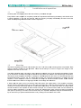
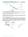
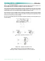
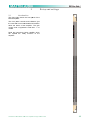
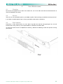
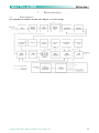
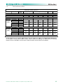
1
MA2.0
High Performance Amplifier
User Guide
The Martin Experience
All material © 2010. Martin Audio Ltd. Subject to change without notice.
Contents
Warning
g notices
s ............................................................................................... 3 1 Insta
allation and
a
operration ..... ..................................................................... 6 1.1 1.2 1.3 1.4 1.5 1.6 Unp
packing ................... ................................................ .............................. 6 Mou
unting ..................... ................................................ .............................. 6 Ope
erating Pre
ecautions
s ............................................... .............................. 7 AC Main connection ... ................................................ .............................. 7 Con
nnecting Inputs ...... ................................................ .............................. 8 Con
nnecting Outputs
O
... ................................................ .............................. 9 2 Setu
up and se
ettings ................................................................................... 10 2.1 2.2 Intrroduction ................ ................................................ ............................ 10 The
e LED indicators ..... ................................................ ............................ 11 3 Prote
ection................................................................................................... 12 3.2 3.3 3.4 Sho
ort circuit protection
n .............................................. ............................ 12 The
ermal protection ..... ................................................ ............................ 12 DC fault prote
ection ..... ................................................ ............................ 12 4 Userr Mainten
nance..................................................................................... 13 4.1 4.2 4.3 Clea
aning ...................... ................................................ ............................ 13
3 Serv
rvice......................... ................................................ ............................ 13
3 Dus
st removal ............... ................................................ ............................ 13
3 5 Warrranty ..................................................................................................... 14
4 7 Tech
hnical no
otes ........................................................................................ 15
5 7.1 7.2 7.3 7.4 Block diagram
m ............. ................................................ ............................ 15
5 ermal Diss
sipation ... ................................................ ............................ 16
6 The
Spe
ecification
n ............... ................................................ ............................ 17
7 Tec
chnical Dra
awing ...... ................................................ ............................ 18
8 All material © 2
2010 Martin Aud
dio Ltd. Subjectt to change with
hout notice
1
Importa
ant safe
ety instructions
s
Caution
To reduce the risk of electric shoc
ck, do not rremove the cover. No user-servicea
u
able parts in
nside. Referr
servicing to qualified service personnel.
Safeguarrds
Electrical en
nergy can perform many
y useful funcctions. This unit has bee
en engineereed and manufactured to
assure yourr personal sa
afety. Improp
per use can rresult in pote
ential electric
cal shock or ffire hazards. In order nott
to defeat the
e safeguardss, observe th
he following i nstructions for
f its installa
ation, use an d servicing.
Approvalls
*
This equip
pment has been
b
tested
d and found
d to comply
y by Compe
etent Body (Directive 89/336/EEC8
EMC) pursu
uant to the product fam
mily standard
rd for audio professiona
al use: EN 555103-1 and EN 55103-2
2
standard); EN61000- 3 - 2, EN 61000 - 3 - 3.
In a domes
stic environm
ment this prroduct may cause radio
o interferenc
ces in which
h case the user
u
may be
e
required to
o take adequ
uate measurres.
his equipment has be
een tested and found to comply by Compeetent Body (Directive
e
NOTES: Th
89/336/EEC
C-EMC) purs
suant to the
e product ffamily stand
dard for aud
dio professsional use: EN 55103-1
and EN 551
103-2 standa
ard ); EN610
000- 3 - 2 , E
EN 61000 - 3 - 3.
This is a class A prod
duct. In a do
omestic env
vironment th
his product may causee radio interrferences in
n
which case
e the user may
m be requiired to take adequate measures.
m
This equipment has been
b
tested and found to comply by Notified Body (Direcctive 2006/9
95/EEC L.V))
pursuant to
o the audio apparatus safety
s
requi rements: Sttandard EN 60065.
NOTE:
This equipm
ment has be
een tested and
a found to
o comply wiith the limits
s for a Classs A digital device,
d
pursuant to
o part 15 of the FCC Ru
ules. These llimits are de
esigned to provide
p
reassonable pro
otection
against harrmful interfe
erence when
n the equipm
ment is operated in a co
ommercial eenvironmen
nt. This
equipment generates, uses, and can
c radiate rradio freque
ency energy
y and, if not installed an
nd used in
accordance
e with the in
nstruction manual,
m
may
y cause harm
mful interferrence to rad
dio commun
nications.
Operation o
of this equip
pment in a residential
r
a
area is likely
y to cause harmful interrference in which
w
case
the user wiill be require
ed to correc
ct the interfe
erence at his
s own expense.
All material © 2
2010 Martin Aud
dio Ltd. Subjectt to change with
hout notice
2
Warn
ning notices
Location
Install the amplifier in a well-ventilate
ed location w
where it will not
n be exposed to high teemperature or
o humidity.
Do not insta
all the ampliffier in a locattion that is exxposed to direct rays of the
t sun, or nnear to hot appliances orr
radiators.
Excessive h
heat can advversely affectt the cabinet and internal components
s.
Installation of the ampliffier in a damp
p or dusty en
nvironment may
m result in malfunction or accident.
Precautio
ons regard
ding installation
Placing and
d using the amplifier for lo
ong periods o
on heat-gene
eration sourc
ces will affecct performanc
ces.
Avoid placin
ng the ampliffier on heat-g
generating so
ources.
Install this a
amplifier as far as possible from tun
ners and TV sets. An am
mplifier instal led in close proximity to
such equipm
ment may ca
ause noise orr degradation
n of the pictu
ure.
WARNING
G: To preveent fire or electric shock:
Do not expose this
t
equipme
ent to rain or moisture.
App
paratus shalll not be exposed to drip
pping or spla
ashing and no objects fillled with liquids, such as
vases, shalll be placed on
o the appara
atus”.
Safety rules
This device must be pow
wered exclus
sively by earrth connected mains soc
ckets in electtrical network
ks compliantt
to the IEC 3
364 or similar rules.
It is absoluttely necessary to verify this fundame
ental requirem
ment of safetty and, in caase of doubt, requires an
accurate ch
heck by qualified personn
nel.
The constru
uctor cannot be considerred responsi ble for eventual damage
es caused too persons, things or data
for the misssing of accura
ate earth link
k.
Beffore powering
g this device verify that th
he amplifier is supplied with
w the correect voltage ra
ating.
Verrify that your mains conne
ection is cap
pable to satis
sfy the powerr ratings of thhe device.
Do not spill wate
er or other liq
quids into or on the unit.
Do not use this unit if the ele
ectrical powe
er cord is fray
yed or broke
en.
Do not remove the
t cover. Removing the
e cover will ex
xpose you to
o potentially ddangerous voltage.
v
No naked flame
e sources suc
ch like lighte d candles sh
hould be plac
ced on the am
mplifier.
Contact the authorized centre
c
for ord
dinary and e
extraordinary maintenance.
Speaker d
damage
Martin Audio MA2.0 amplifiers are
e among the
e most pow
werful professional ampl ifiers availab
ble and are
capable of p
producing much more po
ower than ma
any loudspea
akers can ha
andle. It is thhe user's resp
ponsibility to
use suitable
e speakers with
w the amplifier and to u
use them in a sensible wa
ay that will noot cause dam
mage.
Martin Audiio will not be
e responsible for damag
ged speakers
s. Consult th
he speaker m
manufacturer for powerhandling reccommendatio
ons.
Even if you reduce the gain using the amplifier''s front pane
el attenuation
n controls, it is still possible to reach
full output p
power if the input signal level is high
h enough. A single high-power cresccendo can da
amage highfrequency d
drivers almo
ost instantan
neously, whi le low-frequ
uency drivers
s can usuallly withstand
d very high,
continuous power levells for a few seconds be
efore they fa
ail. Reduce power immeediately if yo
ou hear anyy
speaker "bo
ottoming outt" - harsh pops
p
or craccking distortion that indic
cate that thee speaker voice
v
coil orr
diaphragm iis striking the
e magnet ass
sembly.
All material © 2
2010 Martin Aud
dio Ltd. Subjectt to change with
hout notice
3
Martin Audiio recommen
nds that you use amplifie
ers of this power range for more heaadroom (cleaner sound)
rather than for increased
d volume.
Speaker o
output shock hazarrd
A Martin Au
udio amplifierr is capable of
o producing hazardous output
o
voltag
ges. To avoidd electrical shock, do nott
touch any e
exposed spea
aker wiring while
w
the amp
plifier is operrating.
This manual contains important information
i
on operating your Martin Audio aamplifier co
orrectly and
safety. Please read it carefully before opera
ating your amplifier.
a
If you have aany questions, contactt
your Martin
n Audio dea
aler.
All material © 2
2010 Martin Aud
dio Ltd. Subjectt to change with
hout notice
4
Inttroductiion
The totally new Martin
n Audio MA
A2.0 amplifie
er technolog
gy has changed the w
way the worrld looks att
professiona
al audio amplification. No
o other ampliffiers come close
c
for applications dem
manding high
h power and
long term re
eliability. Thanks to ama
azing reductiions in heat output along with reducctions in weight and the
specific high output po
ower, MA2.0 amplifiers ccan be used
d in an unlim
mited range of applicatio
ons such as
concert tou
uring, opera houses, the
eatres, churrches, cinem
ma, theme parks,
p
televission sound stages and
stadiums.
w
More sound and less weight
Compared to a conventional amplifier, Martin
n Audio MA2
2.0 technolo
ogy offers ve
very high effficiency and
delivers mo
ore power to
o the loudsp
peakers with
h greatly reduced heat dissipation. This greate
er efficiencyy
mption to be
enables dim
mensions, weight
w
and power consum
e reduced. The
T
output sstages of th
he amplifiers
typically run
n at 95% efficciency, dissip
pating only 5
5% of the inp
put energy as
s heat.
One of the most interesting charac
cteristics is tthat MA2.0 efficiency
e
is almost indeppendent of output
o
level.
Conventional amplifierss achieve the
eir best efficciency only at
a full rated power
p
outpu t. Since stan
ndard musicc
has an averrage power density
d
of 40
0% of the ma
aximum level, convention
nal amplifierss can easily generate 10
times more heat than MA2.0 amplifie
ers for the sa
ame volume of sound.
Superior Sound-Sonic
c Accuracy
Crystal-clea
w end: the most accura
ar highs and
d a tight, we
ell-defined low
ate reproducction of an audio
a
signal.
Patented design featurres ensure very
v
high pe
erformance over parameters such aas distortion
n, frequencyy
response, sslew rate, pow
wer bandwid
dth and dump
ping factor.
gh Reliability
y
Totally Digital with Hig
The MA2.0 series is based on PWM
M technologyy that has be
een used for 30 years orr more in pow
wer supplies
and inverters. PWM pro
ovides high reliability, sm
mall size, low
w weight and high efficieency. A PWM converterr
works as a high frequ
uency sampler, convertiing the variable amplitu
ude (audio) signal into an impulse
sequence w
with average value equal to the audio input.
MA2.0 amp
plifiers use ve
ery high sampling frequen
ncies to obta
ain high perfo
ormances accross the aud
dio band.
Compact & Lightweigh
ht
Martin Audio MA2.0 amplifiers
a
offfer incrediblyy compact dimensions are very ligghtweight making
m
them
excellent fo
or application
ns where spa
ace and weiight saving are
a importan
nt. They alsoo offer excellent ease off
use.
Always Goe
es On
The Show A
The MA2.0 is completely protected against
a
everry possible error in operation and aree designed to
o work underr
w deliver maximum pow
wer with max
ximum safety
y and increaased long-terrm reliability.
every condiition. They will
Anticipating
g potential pro
oblems at the design sta
age means yo
our show alw
ways goes onn!
All material © 2
2010 Martin Aud
dio Ltd. Subjectt to change with
hout notice
5
1
1.1
Insta
allation and
a operration
Unpack
king
Carefully op
pen the shipp
ping carton and
a check forr any noticea
able damage
e.
Every Martin Audio amp
plifier is completely teste
ed and inspec
cted before leaving
l
the fa
factory and should
s
arrive
in perfect co
ondition. If you
y find any damage, no
otify the shipping compan
ny immediateely. Be sure to save the
carton and a
all packing materials
m
for the
t carrier's inspection.
1.2
Mountin
ng
The MA2.0 amplifiers will
w mount in a standard 1
19" rack. Fou
ur front pane
el mounting hholes are pro
ovided. Rearr
support mo
ounting holess are also provided.
p
Th
hese should always we used to su pport the weight of the
amplifier at the rear in a 19” rack.
Your MA2.0
0 amplifier usses a forced--air cooling ssystem to ma
aintain a low, even operaating tempera
ature. Drawn
by an intern
nal fan, air en
nters through
h the slots in
n the front pa
anel and cou
urses over annd through components.
c
The MA2.0 series ampllifiers feature
e an "intellig ent" variable
e-speed DC fan which iss controlled by
b heat sinkk
temperature
e sensing circuits: the fan speed w
will increase only when the
t
temperaature of eithe
er heat sinkk
requires it, which keepss fan noise to a minimu
um and help
ps cut dust accumulation
a
n inside. Und
der extreme
thermal load
d, the fan willl force a very
y large volum
me of air thro
ough the hea
at sinks.
If either hea
at sink gets too hot, its sensing circcuit will reduce the outpu
ut power. If the amplifier overheats,
another sen
nsing circuit shuts
s
down its circuit to ccut off powerr until it cools
s to a safe teemperature. The
T exhaustt
cooling air is forced outt through the
e rear of the
e chassis (se
ee below), so
o make suree there is en
nough space
around the sides of the amplifier to allow the airr to escape. If it is rack mounted,
m
maake sure the
e exhaust airr
can flow witthout resista
ance. If you are
a using a rrack with clo
osed backs, there must bbe at least one
o standard
rack space of opening in the front of the rack forr every four amplifiers. Amplifiers
A
maay be stacked directly on
top of each other (no sp
pace needed between un its), starting from the botttom of the raack.
All material © 2
2010 Martin Aud
dio Ltd. Subjectt to change with
hout notice
6
1.3
Operating Precau
utions
Make sure the AC maiins voltage is correct an
nd is the sam
me as that printed
p
on thhe rear of th
he amplifier.
Damage ca
aused by con
nnecting the amplifier to improper AC
C voltage is not coveredd by the warrranty. Make
sure the pow
wer switch iss off before making
m
any in
nput or outpu
ut connection
ns.
It is alwayss a good ide
ea to have the gain co ntrols muted
d during pow
wer-up to prrevent speak
ker damage
particularly if there is a high
h
signal le
evel at the in puts.
Whether yo
ou purchase
e them or build them yo
ourself, use good quality input andd speaker cables.
c
Mostt
intermittent problems arre caused by
y faulty cabl es. Use goo
od quality connectors andd cable alon
ng with good
soldering te
echnique to ensure
e
trouble free reliab ility.
1.4
AC Main
n connecttion
Warning: b
before conn
necting to mains
m
be surre that the amplifier is set to the ccorrect mains voltage.
The AC Main connection is made via the IEC typ
pe connector on the rearr panel. The picture below
w shows the
connection to the ampliffier. Be sure that your AC
C mains pow
wer source has the requirrements indicated in this
manual. Th
he amplifier is a resistiv
ve load for tthe mains network, miniimizing the reactive pow
wer and the
harmonic diistortion on the
t current. The
T system allows perfo
ormance to be maintainedd even in cirrcumstances
of varying tthe mains vo
oltage. Is important to c
connect the
e ground forr safety, do
o not use ad
dapters thatt
disable the
e ground connection.
All material © 2
2010 Martin Aud
dio Ltd. Subjectt to change with
hout notice
7
1.5
Connec
cting Inputts
Input conne
ections are made
m
via the 3-pin XLR-fe
emale on the
e rear of the amplifier.
a
The figure b
below showss the connecttion of analog
g input for ba
alanced and unbalanced line. You ca
an use eitherr
configuratio
on, but you must
m
considerr that unbala
anced long lin
nes can intro
oduce noise iin the audio system.
s
The Link sw
witch located
d in the rear panel is for d
direct paralle
eling the rear input conn ectors. You can use the
remaining in
nput connecttor to carry signal
s
to othe
er amps.
All material © 2
2010 Martin Aud
dio Ltd. Subjectt to change with
hout notice
8
1.6
Connec
cting Outp
puts
Warning: th
here are leth
hal voltages
s at the loud
dspeaker co
onnectors when
w
the am
mplifier is turrned on. To
prevent any
y damages turn the am
mplifier off be
efore conne
ecting the lo
oudspeaker..
Output conn
nectors are made
m
via Neutrik Speako
on connectorrs. Consult th
he wire gaugge chart to fin
nd a suitable
wire gauge to minimize power and damping facctor losses in
n the speaker cables. Thhe outputs ca
an also workk
in bridge mo
ode. In norm
mal stereo or linked mono
o mode, for each
e
channel 1+ of the S
Speakon connector is the
positive output and the 1- pin of the Speakon sho
ould be treatted as the ne
egative outpuut.
Note: Chan
nnel B is run
n out of phas
se internallyy, corrected by reversing
g the connecctions from the
t
amplifierr
output to the output con
nnecter Chan
nnel A is run
n in phase. By
B having channel A andd B operating
g in opposite
polarity, the
e energy storrage in the power
p
supplyy is more efficient. This is
s significant ffor signals below
b
100Hz
(sub bass e
etc.) and improves the po
ower bandwid
dth.
Be sure to use balance
ed inputs on
n all measurrement equipment (inclluding oscillloscope pro
obes) if you
are bench ttesting.
No
ote: in Bridge mode the link switch must be sw
witched to “o
on”
and th
he gain conttrols of both
h channels must
m
be set to the samee level
All material © 2
2010 Martin Aud
dio Ltd. Subjectt to change with
hout notice
9
2
2.1
S
Setup an
nd setting
gs
Introduc
ction
The figure right shows the front pa
anel of the
MA2.0 Amp
plifier.
The front p
panel contro
ols and indic
cators give
the user tottal control an
nd detailed information
about the status of th
he amplifier. The gain
control use
es a logarith
hmic scale frrom -∞ to
+32dB.
Read the instructions below careffully which
will explain
n the man
ny functions of the
amplifier.
All material © 2
2010 Martin Aud
dio Ltd. Subjectt to change with
hout notice
10
2.2
The LED
D indicato
ors
The figure b
below showss the front panel of the MA
A2.0. The cliip LED, when
n lighting, inddicates the clipping
c
state
e
for the output stage of th
he correspon
nding channe
el. The signa
al, -18dB and
d -6dB LEDss operate as V-meter and
d
the signal L
LED is illumin
nated when the
t signal is present in th
he input stage of the corrrespondent channel.
c
The
e
"ready" LED
D, when illum
minated, indic
cates that th e start-up tim
me after pow
wer-on is finisshed and the
e amplifier iss
ready to usse. The "tem
mp" LED, wh
hen lit, indica
ates that the
e output stage of the coorresponding
g channel iss
reducing the
e output pow
wer due to an
n over-heated
d state.
All material © 2
2010 Martin Aud
dio Ltd. Subjectt to change with
hout notice
11
3
3.1
Prote
ection
Turn-On
n-Turn-Offf muting
For about fo
our seconds after turn-on
n, and immed
diately at turn
n-off, the amplifier outputts are muted.
3.2
Short circuit prottection
A short circcuit protection system sa
afeguards the
e amplifier's output trans
sistors underr short circuits and otherr
stressful loa
ads. It is com
mpletely inau
udible when iinactive. In th
he event of a short circu it condition, the red LED
D
will be illum
minated. The amplifier pro
otection has an auto reset mode which will attem
mpt of reset the amplifierr
for normal u
use after 2 seconds.
s
If the
t short circcuit is still prresent the amplifier will aattempt to re
eset every 2
seconds until the short is removed.
3.3
Therma
al protectio
on
The MA 2.0
0 amplifier uses
u
a contin
nuously varia
able speed fan
f
to assistt cooling (thee fan speed
d changes in
n
response to
o the amplifie
er's cooling requirementss). If the hea
atsink tempe
erature reachhes approxim
mately 75°C,,
the "TEMP"" LED illumin
nates and the
e output pow
wer is reduce
ed to preventt damages too the output stage. If the
e
temperature
e rises above
e 85°C the th
hermal sensiing circuitry will
w mute eac
ch channels power sectio
on. Once the
e
heatsink ha
as cooled be
elow 85°C th
he amplifier w
will automatiically un-mutte but the T
TEMP LED will
w remain litt
until the tem
mperature has
h
dropped to 75°C. It is possible to reduce th
he temperatture reducing
g the outputt
power.
3.4
DC fault protectio
on
If DC or exxcessive sub
bsonic energ
gy appears a
at a channel output, an instantaneoous protection circuit willl
mute both cchannels of the amplifierr. The ampli fier shutdow
wn is used in
nstead off of speaker relays, therebyy
improving th
he damping factor
f
and re
eliability of th e MA2.0.
3.5
Input / Output
O
pro
otection
An ultrasonic network de
ecouples RF
F from the ou
utputs and ke
eeps the amp
plifier stable w
e loads.
with reactive
All material © 2
2010 Martin Aud
dio Ltd. Subjectt to change with
hout notice
12
4
4.1
User Maintenanc
ce
Cleanin
ng
Disconnect the amplifie
er from the AC
A main sou
urce first; use a soft clotth and mild nnon-abrasive
e solution to
clean the fa
aceplate and chassis.
4.2
Service
e
There are n
no user-servicceable parts in your MA2
2.0 amplifier. Refer servic
cing to qualiffied technical personnel.
If your MA2.0 amplifier needs
n
repair, contact you
ur Martin Aud
dio dealer or distributor.
4.3
Dust rem
moval
Particularly in dusty en
nvironments, the front fiilters clog with
w
dust and
d dirt after pprolonged use,
u
this will
interfere witth cooling. Yo
ou may use compressed
d air to remov
ve the dust frrom filters.
To remove air filters forr more comp
prehensive ccleaning, uns
screw the rettaining screw
ws and pull the
t covering
grill forward
d.
All material © 2
2010 Martin Aud
dio Ltd. Subjectt to change with
hout notice
13
5
Warra
anty
Martin Audio MA2.0 is warranted
w
ag
gainst manuffacturing deffects in mate
erials or craftftsmanship over
o
a period
d
of 3 (three) years from the date of orriginal purcha
ase.
During the w
warranty perriod Martin Audio will, at iits discretion
n, either repair or replace products wh
hich prove to
o
be defective
e provided th
hat the produ
uct is returne
ed in its origin
nal packaging, shipping pprepaid, to an authorised
d
Martin Audio service agent or distrib
butor.
Martin Audiio Ltd. cannot be held responsible
r
ffor defects caused
c
by unauthorised modification
ns, improperr
use, neglige
ence, exposu
ure to inclem
ment weatherr conditions, act of God or accident, oor any use off this productt
that is not in accordan
nce with the
e instructionss provided by
b Martin Audio. Martinn Audio is not
n liable forr
consequenttial damagess.
This warran
nty is exclusive and no otther warrantyy is expressed or implied
d. This warraanty does no
ot affect yourr
statutory rig
ghts.
All material © 2
2010 Martin Aud
dio Ltd. Subjectt to change with
hout notice
14
7
7.1
T
Technica
al notes
Block diagram
d
The diagram
m below show
ws the ampliifier block dia
agram (1 Channel shown
n).
All material © 2
2010 Martin Aud
dio Ltd. Subjectt to change with
hout notice
15
7.2
Therma
al Dissipattion
Martin
n Audio MA2.0
M
Level
Load
Rated
Power
Sw
witch in off position*
Power onn, amplifier in iddle mode
Pink Noise
(1/8 rated
power)
Pink Noise
(1/4 rated
power)
8Ω / Stereo
16Ω / bridgedd
4Ω / stereo
8Ω / bridged
2Ω / stereo
4Ω / bridged
Watt
2 x 600
1 x 1200
2 x 1000
1 x 2000
N/A
N/A
8Ω / Stereo
16Ω / bridgedd
4Ω / stereo
8Ω / bridged
2Ω / stereo
4Ω / bridged
2 x 600
1 x 1200
2 x 1000
1 x 2000
N/A
N/A
AC Maains
230V AC 115V AC
0.13
0.2
0.09
0.4
Out
Watt
W
In
I
Dissipaated
0
0
1..71
35
3
1.7 1
355
Ampeere
Watt
W
Thermaal Dissipation
BTU/hr
Kcal/hr
5.8
119
1.5
30
BTU/hr
Kcal/hr
1
2
150
188
733
247
62
1.5
3.1
250
313
988
332
84
N/A
N/A
N/A
N/A
N
N/AA
N/A
N/A
1.8
3.6
300
375
1100
375
95
2.9
5.8
500
625
1600
546
138
N/A
N/A
N/A
N/A
N
N/AA
N/A
N/A
*Power abssorbsion with amplifier sw
witched off is not zero bec
cause to com
mply with EN
N60065/IEC 60065:20016
12 all amplifier circuitryy must includ
de a “bleed” resistor acro
oss the inco
oming AC maains power to
t discharge
residual currrent to preve
ent the risk of
o shock from
m an amplifier disconnecte
ed from the m
mains.
All material © 2
2010 Martin Aud
dio Ltd. Subjectt to change with
hout notice
16
7.3
Specific
cation
POWER RE
EQUIREMEN
NTS
Power supp
ply......................................................................................115-230V (-15%, +
+15%) (50/60Hz) 800VA
................... ........................................................... .................. 0°C
Operating te
emperature ....................
.
0 to 45°C
Weight.................................................................. ........................................................... ............ 7.3K
Kg (16.1 lbs)
External dim
mensions
Width………
………………………………
………………
……………………..……..…
…..Standard 19” Rack: 483mm (19”)
Depth………
……..…………
………………
……………… …….………………………
…………...… ……………3
358mm (14”)
Height………
………………
………………………………
…….…………
………………
……………1 R
Rack Unit: 44
4mm (1.75”)
AUDIO SEC
CTIONS
Bandwidth ((1W, 8Ohm)........................................ .......................................................... .................10
0Hz, 30KHz
Damping factor (8Ohm).................................................................................................................. at 100Hz
1
> 500
Slew Rate ((8Ohm).................................................................................................>50V/μ
μS (input filte
er bypassed)
S/N ratio......................................................................................................................>1112dB/A (20Hz to 20KHz)
Distortion T
THD…………………………
………….……
…….…..... < 0.05% from 1W to full poower (Typica
ally <0.01%)
Intermodula
ation SMPTE
E ……………………………
………..…. < 0.05% from 1W to full poower (Typica
ally <0.01%)
Intermodula
ation DIM 30........................................ ............... <0
0.02% from 1W
1 to full pow
wer (Typicallly <0.005%)
Inputs............................................................................Balance
ed to ground, XLR femalee with paralle
el Male XLR
R
Impedance................................................................................................10
0KOhm eachh leg balance
ed to ground
Gain ………
………………………………
…..……………
….….…………………...…
……………… ………………
…….....32dB
Outputs….…
……...…........................Ne
eutrik 4-pole
e Speakon co
onnectors (pins 1+ 2+ parralleled, 1- 22 paralleled)
OUTPUT SPECIFICATIIONS
Output Pow
wer
EIAJat 1KH
Hz, 1% THD
8Ω Per Cha
annel…………
….……………
………………
…………………
………………
………………
………………..…….600W
4Ω Per Cha
annel…………
….……………
………………
…………………
………………
………………
…………………
…….1000W
16Ω Bridged
d……………
…………………
………………
………………………………
………………
…………………….1200W
8Ω Bridged………………
………………
…………………
………………
………………………………
……..……….……2000W
FEATURES
S
Indicators…
………………………………
………………
…………………
…………….…
…..……2 x 4 segment LE
ED bargraph
Over-tempe
erature foreccasting, thermal protecction, short circuit prote
ection, overrload outputt protection,
p limiter and permanen
temperature
e controlled air cooling system, clip
nt signal lim
miter, auto-re
eset system,
parallel inpu
uts switch, in
nput signal prresence LED
D.
All material © 2
2010 Martin Aud
dio Ltd. Subjectt to change with
hout notice
17
7.4
Technic
cal Drawing
All material © 2
2010 Martin Aud
dio Ltd. Subjectt to change with
hout notice
18