1
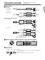
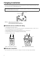
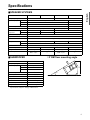
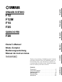
English
SPEAKER SYSTEMS
Français
F12
F12M
F15
F25
Deutsch
SUBWOOFER
F28
Thank you for purchasing a YAMAHA product. To obtain
maximum performance from your YAMAHA speaker system and ensure many years of trouble-free operation, we
recommend that you read this Owner’s Manual thoroughly
before use and keep it for future reference.
Contents
Precautions . . . . . . . . . . . . . . . . . . . . . . . . . . . . . . .2
Connection example. . . . . . . . . . . . . . . . . . . . . . . . .3
Hanging installation . . . . . . . . . . . . . . . . . . . . . . . . .4
Specifications . . . . . . . . . . . . . . . . . . . . . . . . . . . . . .5
Technical Data . . . . . . . . . . . . . . . . . . . . . . . . . . . .32
Dimensions . . . . . . . . . . . . . . . . . . . . . . . . . . . . . .36
Additions
取扱説明書
日本語
Español
Owner’s Manual
Mode d’emploi
Bedienungsanleitung
Manual de instrucciones
Precautions
AVOID EXCESSIVE HEAT, HUMIDITY, DUST
AND VIBRATION
When choosing a location for your speakers, avoid the
following:
• Direct sunlight, high temperatures (such as near heaters), or excessively low temperatures.
• High humidity.
• Areas subject to excessive dust accumulation and
vibration.
• Non-level or unstable surfaces.
HOW TO POWER UP YOUR SOUND SYSTEM
To avoid damage to your speakers and other parts of
your system, when you turn on your system, ALWAYS
turn the power amp on last! This will avoid loud, damaging pops that will annoy your audience, and blow
your speakers. When you power down, the amplifier
should ALWAYS be turned off first to avoid the same
problems.
■ To protect your speakers
When choosing a power amplifier to use with your
speakers, make sure that its power output matches the
speakers’ power capacity (refer to the “Specifications” on page 5). Even if the amplifier’s power output is lower than the speakers’ PGM (program) power
capacity, the speakers may be damaged when clipping
of a high input signal occurs.
The following may cause damage to speakers:
• Feedback caused when using a microphone.
• Continuous high sound pressure level produced by
electronic instruments.
• Continuous high-power output distorted signals.
• Popping noises caused by turning on equipment, or
by connecting or disconnecting system components
while the amplifier is turned on.
MAKE SURE THE POWER IS OFF BEFORE
MAKING OR REMOVING CONNECTIONS
This product, when used in combination
with amplification and/or additional
loudspeakers, may be capable of producing sound levels that could cause permanent hearing loss.
Always turn the power switches of system components
OFF prior to connecting or disconnecting cables. Failure to do so may result in damage to speakers as well as
to connected equipment.
DO NOT operate at high volume levels or
at a level that is uncomfortable. If you
experience any discomfort or ringing in
the ears, or suspect an hearing loss, you
should consult an audiologist.
DISCONNECT CABLES BEFORE MOVING
THE SYSTEM
To prevent short circuits or breakage of cables, always
disconnect cables prior to moving system equipment.
MATCH CONNECTOR POLARITY
When using two or more speaker systems, be sure
match the polarity (+/–) of the speaker system connectors to those at the amplifier. If the polarities do not
match, the sounds produced by the speakers will interfere with each other, making it impossible to achieve a
well-balanced sound field.
KEEP THIS OWNER’S MANUAL IN A SAFE
PLACE FOR FUTURE REFERENCE
2
SPEAKER HANDLES
The handles on your speakers are for transportation.
The F12M/F25/F28 models are not designed for suspension or hanging. Only the F12/F15 models are
designed for suspension. Please consult a qualified
engineer for proper hanging techniques.
Fly-Ware
Hang correctly according to the instructions on page 4.
Connection example
• SPEAKER SYSTEMS: F12/F12M/F15/F25
• SUBWOOFER: F28
●Stand alone
Full-range position
Mixer
Power amp
F12/F12M/
F15/F25
HF
Bi-amp position
Power amp
F12/F12M/
F15/F25
Mixer
LF
●Use combined with subwoofer
Normal
Power amp
Français
Polarity
Reversed
2 Use as bi-amp
speaker system
Crossover
1.4 kHz (24 dB/oct., Gc=–3 dB)
1 2-way crossover
Polarity
Normal
HF
Full-range position
Power amp
F12/F15
Mixer
LF
Normal
Power amp
Crossover
80 Hz (18 dB/oct., Gc=–6 dB)
Deutsch
1 Use as full-range
speaker system
English
■ Connections
F28
2 3-way crossover
Polarity
Reversed
HF
Bi-amp position
Power amp
F12/F15
Mixer
LF
SLF
Normal
Power amp
Español
Normal
Power amp
F28
Crossover
LF/HF; 1.4 kHz (24 dB/oct., Gc=–3 dB)
SLF/LF; 80 Hz (18 dB/oct., Gc=–6 dB)
■ Speaker system and Neutrik NL4FC connector connections
1+
2+
1–
Full-range operation
+
1+
–
1–
2+
2–
Bi-amp operation
LF+
1+
LF–
1–
HF+
2+
HF–
2–
Subwoofer
+
1+
–
1–
2+
2–
日本語
2–
Neutrik NL4FC connector
The F12/F12M/F15/F25 also support bi-amp drive.
FULL-RANGE
PIN
1±=INPUT
2±=N.C.
BI-AMP
PIN
1±=L.F.
2±=H.F.
For bi-amp drive, switch the mode switch from FULL-RANGE to BI-AMP with a
flat-bladed screwdriver.
Caution: • Do not switch the mode switch during operation.
3
Additions
■ Bi-amp drive
Hanging installation
The F12/F15 can be installed hanging. Remove the four countersunk screws on the top or bottom of the speaker system,
screw in the four accessory eye bolts and hang with wire.
When hanging the speaker system, carry out the work under the guidance of an expert with a safe method appropriate to the actual installation and environment.
Eye bolt (3/8")
Countersunk screw
Warning:
• Always use the accessory eye bolts.
• Always hang with four eye bolts on one surface.
• Do not use the handle to hang the speaker system.
■ Standards and use conditions for flying
1 Always hang from four points. (Figure 1)
2 Use the fittings for the F12/F15 with a total load no greater than 172 kg including the speakers, eye bolts, wires, etc.
3 Use with a hanging angle of no greater than 45°. (Figure 2)
4 When hanging in a vertical array, use no more than 4 levels of F12s or 3 levels of F15s.
5 Verify the strength of wire rope, ceiling fittings, and connection fittings.
* 1–5 above are reference values.
45° maximum
(Figure 1: Always hang from four points.)
(Figure 2: Retraction angle 45° maximum)
■ Maintenance inspection
Parts can deteriorate due to wear, corrosion, etc. during use. For the sake of safe usage, inspect periodically.
4
Specifications
Model
F12
F12M
Frequency Range
55 Hz to 20 kHz
45 Hz to 20 kHz
NOISE
350 W (EIA RS-426)
PRGM
700 W
1400 W
MAX
1400 W
2800 W
Sensitivity
4Ω
98 dB (W, m)
99 dB (W, m)
60°
40°
60°
Vertical
40°
60°
40°
1.5 kHz
NEUTRIK NL4MPR ×2
Input Connectors
Mode Switch
Components
98 dB (W, m)
Horizontal
Crossover Frequency
Full Range & Bi-Amp
LF
12" cone (JAY5130)
HF
15" cone (JAY6150)
15" cone × 2 (JAY6150)
3" Titanium diaphragm driver (JAY2120)
Bass Reflex Type
Dimensions (W × H × D)
Weight
Accessory
500 × 714 × 375 mm
705 × 465 × 447 mm
34 kg
3/8" Shoulder Eye
Bolts × 4 pcs
■ SUBWOOFER
Model
575 × 1225 × 550 mm
32.5 kg
40 kg
63 kg
—
3/8" Shoulder Eye
Bolts × 4 pcs
—
✩ F12M floor mounting angle
F28
NOISE
1000 W (EIA RS-426)
PRGM
2000 W
MAX
4000 W
Sensitivity
4Ω
Input Connectors
NEUTRIK NL4MPR ×2
Components
18" cone ×2 (JAY7020)
Enclosure
Dimensions (W × H × D)
30°
98 dB (W, m)
Bass Reflex Type
1225 × 585 × 655 mm
日本語
Nominal Impedance
Español
35 Hz to 2 kHz
471
Frequency Range
Power Capacity
575 × 855 × 435 mm
Deutsch
Enclosure
Weight
700 W (EIA RS-426)
8Ω
Nominal Impedance
Nominal
Dispersion
F25
Français
Power Capacity
F15
English
■ SPEAKER SYSTEMS
72.5 kg
Additions
Specifications subject to change without notice.
5
Technical Data
■F12/F12M
Frequency Response/Impedance
110
RESPONSE(dB)
100
90
16
80
8
70
60
4
2
20
100
1k
10k
FREQUENCY(Hz)
F12; Horizontal Directivity
F12M;Vertical Directivity
0°
0°
10
20
30
0°
40
50
270°
40
0°
12
10
0
10
0
0
10
0
10
21
0°
20
30
40
30
40
180°
180°
15
21
0°
20
0°
0°
24
30
0°
0
15
0
0°
10
12
20
50
90°
24
30
0°
50
90°
°
60
40
30
°
60
50
270°
°
0°
30
30
• 4kHz
• 8kHz
• 16kHz
0°
33
30
°
0°
33
• 500Hz
• 1kHz
• 2kHz
F12; Vertical Directivity
F12M;Horizontal Directivity
0°
0°
0°
12
180°
21
15
0°
0°
24
32
40
50
270°
40
30
20
20
0°
24
0°
0°
30
15
20
180°
10
0°
0
21
0
0°
10
12
20
50
90°
30
0°
50
90°
°
60
40
30
°
60
50
270°
30
°
0°
0°
30
• 4kHz
• 8kHz
• 16kHz
33
0°
30
°
33
• 500Hz
• 1kHz
• 2kHz
■F15
Frequency Response/Impedance
110
RESPONSE(dB)
100
90
16
80
8
70
60
4
2
20
100
1k
10k
FREQUENCY(Hz)
Horizontal Directivity
0°
0°
10
20
30
0°
40
50
270°
40
0°
12
10
0
10
0
0
10
0
10
21
0°
20
30
40
30
40
180°
180°
15
21
0°
20
0°
0°
24
30
0°
0
15
0
0°
10
12
20
50
90°
24
30
0°
50
90°
°
60
40
30
°
60
50
270°
°
0°
30
30
• 4kHz
• 8kHz
• 16kHz
0°
33
30
°
0°
33
• 500Hz
• 1kHz
• 2kHz
Vertical Directivity
0°
0°
24
30
20
20
0°
日本語
33
Additions
15
180°
40
0°
0°
0°
21
0°
50
270°
15
40
180°
0°
30
21
0°
20
12
10
0°
0
12
0
50
90°
10
50
90°
°
60
20
°
24
30
0°
60
40
°
50
270°
30
30
0°
• 4kHz
• 8kHz
• 16kHz
0°
33
30
30
°
0°
33
• 500Hz
• 1kHz
• 2kHz
■F25
Frequency Response/Impedance
110
RESPONSE(dB)
100
90
16
80
8
70
60
4
2
20
100
1k
10k
FREQUENCY(Hz)
Horizontal Directivity
0°
0°
10
20
30
0°
24
40
50
270°
40
30
10
0
10
0
0
10
0
10
20
30
40
30
40
0°
0°
24
180°
180°
15
21
0°
0°
12
21
0°
20
0°
0
15
0
0°
10
12
20
50
90°
30
0°
50
90°
°
60
40
30
°
60
50
270°
°
0°
30
30
• 4kHz
• 8kHz
• 16kHz
0°
33
30
°
0°
33
• 500Hz
• 1kHz
• 2kHz
Vertical Directivity
0°
0°
20
0°
40
0°
12
180°
15
21
0°
0°
24
34
30
50
270°
40
24
30
20
20
0°
0°
10
15
0
180°
0
21
0°
10
0°
20
12
30
50
90°
40
0°
50
90°
°
60
50
270°
30
°
60
0°
30
°
30
• 4kHz
• 8kHz
• 16kHz
0°
33
30
°
0°
33
• 500Hz
• 1kHz
• 2kHz
■F28
Frequency Response/Impedance
110
90
16
80
8
70
2
20
100
1k
10k
FREQUENCY(Hz)
日本語
60
4
Additions
RESPONSE(dB)
100
35
Dimensions
F12
210
75
°
(106)
D:375
(59)
242
354.7
H:714
W:500
F12M
W:705
47
H:465
50
0
30°
1
60°
D:447
36
日本語
°
75
Additions
D:550
H:855
(105)
°
75
H:1225
245
D:435
(85)
F15
297
428
W:575
F25
287
W:575
37
H:585
F28
W:1225
D:655
Unit:mm
38
CJY0328 R1 1 AP 40
Printed in U.S.A.
Pro Audio Division, #18/3
P.O. Box 3, Hamamatsu, 430-8651, Japan