1
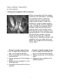
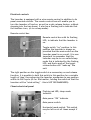
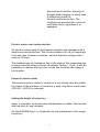
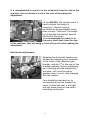
MANUAL
MJDT/MDT 560
English
1
Manual for MJTD, MDT 560
Ensure that tests and installation are carried out in a safe way!
Adjustment guide
Your BEOMAT launcher has undergone a complete pre-delivery inspection
and should not require any adjustment at the time of installation.
Should your launcher not be performing correctly, before any
adjustments are made, please check the following:
1. Confirm that the launching arm is straight. Remove the arm and
visually inspect the same (after some time of use, a slight “banana
shape” in the working direction is normal and acceptable).
However, if the arm is bent either up or down, it will severely
effect the target flight, or cause target breakage. In such a case,
replace the arm before checking further. If you think the arm needs
adjustment please see next page.
2. Verify that the elevator is adjusted correctly. The ideal clearance
between the highest point of the elevator and the bottom rim of
the target, should be between 3mm (1/8”) - 6mm (1/4”).
3. Confirm that the target retainer brush is “holding” the target close
to the launching arm (permissible distance between the target and
the launching arm is 6mm (1/4”)
Following instructions will help you maintain your BEOMAT launcher.
Please check your launcher on a regular basis. Keep the launcher clean
and do not load with damaged targets.
Further trouble shooting is available at the end of this manual.
2
WARNING!
Ensure that the power is turned off and the launcher is in a
disarmed position when adjusting or maintaining the launcher!
All work on electrical appliances should for safety reasons be
performed by a qualified electrician.
Installing the machine
Depending upon the size of the opening in your trap house, you may
need to remove the magazine. This is done by removing the circlip at
the magazine center shaft, lift the black knob, (the magazine lock) and
turn the magazine slightly in the clockwise direction. Release the knob,
then simply lift the magazine straight off the launcher. When installling
the magazine again just assemble in revers order. Then turn the
magazine clockwise and it will automatically lock in position.
When handling the machine, be careful not to use the launching arm,
or the primary launch table (the target loading shelf) as a handle. Any
damage to either of those components will render the machine
inoperable.
Then fasten the machine to the pier and install the magazine .
The Beomat double launcher
During the design and development of the Beomat 500 series, the
American Trap Doubles machine, our goal as always – to provide the
shooting facilities with the most versatile machine possible. It is our
firm belief that we now have a machine that not only is the most
versatile unit in the market, but also durable as well as simple to
operate. Offering a winning combination of performance and features
the Beomat MJTD or MTD560 is specifically designed for today´s
expanding needs in the clay target shooting fields. For example, the
Beomat double launcher will not require any pre-heating or warming up
of any component on the machine. Due to its advanced design, the unit
automatically shuts down to a sleep mode if no activity has been
detected in the last five minutes. This will substantially reduce the
power consumption as well as wear on the machine, it will of course
automatically resume operation at the first push of the target release
button. Further, the on-board power supply and electronic control unit
are extremely easy to service should there ever be a need for service.
3
Both the machine and the wire remote, are equipped with flashing red
LED´s to alert you that the machine is ”still on” even though it may be
in a sleep mode. The machine is very simple to operate, change from
single to double, or vice versa, is done in one minute.
The following instructions is furnished for informational use only, and is
subject to change without notice..
Operating Instructions for Beomat 500 series launcher
There should be no need to adjust any mechanism on the launcher
itself. The unit has been carefully tested and adjusted, and is ready to
throw targets.
At all times when changing settings on the machine, the power must be
turned off and the launcher released.
Before proceeding with the centering of the field, targets must be
loaded and the machine set in a single target mode.
The ball joint connecting rod at the base of the launcher, must be
disconnected at the outside ball joints and positioned inside the main
bearing hub on the base, when the machine is to be oscillating
horizontally. A reminder; of the fact that the launcher is ”freefloating” on the base when set in singles mode.
Magazine lock mechanism
To release the magazine for target
loading, pull the black knob straight
upwards and turn the magazine in its
normal (clockwise) rotation. Once
released it will turn freely until it has
completed the circle, it will then lock
into place again. (Move the magazine
until you hear the ”click” from the lock
plunger). Should you forget to lock the
magazine at the time of loading it will
be possible to ”blank fire” the machine
16 times, it will then lock itself
automatically, this procedure is NOT
RECOMMENDED.
4
Centering the machine on the field
Start by turning the machine fully to the left, (make sure that the field
is clear and that targets can be thrown safely) release one or more
targets while observering the target path. Then move the machine fully
to the right side and repeat the process. The objective here is to
determine that the machine is dispersing the targets equally from side
to side, if not, proceed with the following. By using a 10 mm Allen
wrench loosen the clamping bolt at the back of the connecting arm for
the horizontal oscillations. Now, by shifting (lightly forcing) the
machine over the side at which you came up short with the target
spread will then shift the ”target window”, re-tighten the bolt and
again check the field position. If not correct repeat the process.
Main spring adjustment
Setting the target throwing
distance is easily done by the
multipurpose tool a 3/8” drive
ratchet. A spring tension
indicator as shown, is very
helpful when changing from
single to double throw. Silmply
insert the ratchet and ”turn up”
the spring tension to desired
distance of 50 yards for single
target, mark the position of the
gauge with a black marker pen for reference. When throwing doubles,
the spring tension must be increased by about 4-5 turns with the
ratchet, establish the spring tension for doubles, now, also ark the
doubles position. The now established spring tension on the indicator
will remain very accurate, and there will be no need to repeatedly reestablish the throwing distance.
5
Changing the base setup for singles or doubles
Setting up your Beomat for doubles as follows; The launcher is
equipped with a lift leg where two bolts are located on the inside of
the assembly, providing two settings, one for doubles which need to be
the lowest setting, and has a separate adjusting bolt, the rear most.
The other position is upwards for throwing single targets and has an
adjusting bolt the front most, to work together with a movable steel
block. Both adjustments are to be ”pre-set”, and when changing
between singles or doubles the only adjustment needed is to lift the
machine with its handle and either insert the steel block for singles or
take it out of position for doubles.
Magazine indexing, single/double feed
Before proceeding to change the magazine feed (indexing) please note
the following; As always, shut off power and release the launcher
before making any changes. When using the safe release toogle switch,
use the momentary function as briefly and quickly as possible, so that
the machine mechanism does not advance substantially. If the
mechanism has advanced too faar, it will not be possible to change the
drive member. In such case re-start the machine once again, repeat
the safe release procedure as briefly as possible, you may then change
the magazine mode.
Setting the magazine to single target delivery
Before proceeding with this
change, please see the note
above.
Setting (changing) the magazine
to feed single target is done by
removing the target stack as
shown, insert the forked end of
the 3/8”ratchet as a push rod
on the top surface of the
magazine drive member, push
firmly straight downwards to its
bottom position. It is very
important that the drive
member moves all the way
6
down, a distinct ”snap action”
is to be noticed.
Changing the magazine feed to doubles
Before proceeding with this change,
please see the note above. Changing
the magazine drive to feed two
targets is done by removing the
target stack as shown, insert the
forked tool (with its single support
”leg” downwards onto the magazine
plate) in under the magazine drive
member using the tool as pry-bar,
pushing down on the handle firmly,
thus moving the drive member to its
upward position. It is very important
that this drives member is being
moved all the way up, a distinct
”snap action” should be noticed. The
magazine will now index twice and
deliver two targets onto the primary
launch table.
Change to single target throw
Change to double target throw
1. Set, or make sure that the lift
1. Set, or make sure that the lift
leg is in its upward position.
leg is in its downward position.
2. The connecting rod on the base 2. Spring tension set at its doubles
disconnected.
mark.
3. Spring tension set at the singles 3. Magazine drive member in its
mark.
upward position.
4. Magazine drive member is in its
down position.
5. Horizontal drive switch to its on
position.
7
Electrical controls
The launcher is equipped with a wire remote control in addition to its
panel mounted controls. The remote control box will enable you to
turn the launcher off and on, as well as a safe release feature, without
stepping into the trap house. It also has a flashing led to indicate that
the machine is on, (or in a sleep mode).
Remote control box
Remote control box with its flashing
LED, to indicate that the launcher is
on.
Toggle switch ”on” position. In this
position the launcher is always on,
provided that the main switch on the
launcher panel is on as well. It is now
important to remember that the
launcher may be in a so called sleep
mode this is indicated by the flashing
LED, and that a push of the target
release button will ”wake up” the
unit.
The right position on the toggle switch is a momentary on and release
function. It is possible to hold this switch in this position for a variable
length of time, thus advancing the launcher mechanism to any position
within its 360° cycle.(Or for that matter, holding the switch so that the
launcher will be ”wind milling” – this is NOT RECOMMENDED).
Chassis electrical panel
Flashing red LED, sleep mode
indicator.
Main power ”ON” indicator
Main power switch.
Horizontal mode switch. This switch
may be left on at all times except if
8
the machine is used for shooting of
straight ahead targets, at which time
it should be turned off.
Vertical oscillation switch. The
machines are prewired for a vertical
oscillation drive, regardless if so
equipped.
Electric motor over load protection
All electric motors used on the Beomat machines are equipped with a
simple overload protection. The circuit breakers will vary in amperage
from one type of motor to another, and are typically ranging from 4
amps to 12 amps.
The breakers may be located on any of the sides of the connecting box,
in some cases the rating is shown on outside ”button”. If not, it will be
necessary to remove the top cover on the box to obtain the rating of
the breaker.
Power & control center
The machines power center is located in a very sturdy steel box within
the frame of the machine. It consists of a easy relay and a transformer
(220 VAC -24 VDC) is mounted.
Setting the height of trajectory
Again a reminder; as always when adjustments are made, the launcher
must be shut off and released.
On the MJTD500 there´s a turnbuckle for the adjustment of the target
trajectory.
9
It is recommended to reach in to the turnbuckle from the side of the
machine, thus not being in front of the unit while making the
adjustment.
On the MTD500, the vertical motor is
used to adjust the height of
trajectory. Stop the vertical
oscillation at an approximate level,
then you may ”fine tune” the height
by turning the knurled bolt head at
the back of the motor.
It is recommended to reach in to
the motor shaft knob from the side
of the machine, thus not being in front of the unit while making the
adjustment.
Belt tension adjustment
Adjusting the drive belt tension may
be done by loosening the 2 fasteners
at the front of the reduction gear
bracket, and the 3rd at the rear of the
bracket as shown, then by tightening
up or (backing off) the tension bolt,
as shown, will move the entire
gearbox/motor in/out, thus changing
the belt tension.
Care should be exercised not to
increase the drive belt tension too
much. A drive belt that is too tight
will put undue strain on the entire
launching mechanism.
10
Launching arm Timing adjustment
The launching arm should be
positioned as shown in this picture. A
so called ”Top dead Center” has been
established, and the most favorable
setting for the launching arm is 3-4
degrees before top dead center, BTDC.
The very back side of the launching
arm is to be regarded as the
reference line, when this back side at
the very end (tip) of the arm is lining
up with the leftmost timing mark, it
is then said to be 3° before TDC.
Before adjusting the timing, it will be necessary to remove the
magazine and the ring gear. (The machine may be test fired without
the magazine or ring gear).
The adjustment of the launching arms
stopping point (ready to fire position)
is done via the micro switch, which is
located at the magazine drive
member. By loosening the set screws
(2 ea.) in the inner bearing collar
(race) about 11/2 turn, (use a 3 mm
Allen tool) the collar may now be
turned on the shaft thus changing the timing. (Use a pair of channel
lock pliers to grab the collar). Do not forget to re-tighten the set
screws when finished. The adjustment is extremely precise and may
require that you practice a couple of times before getting it right.
Moving the collar counter-clockwise will stop the arm earlier – turning
it clockwise will stop the arm later. (If you adjust too far the machine
will ”windmill”. Note, - this view is from the rear of the machine.
11
Troubleshooting
Problem
The trap does not
start
Cause
No power
Targets are not
released
Two targets
delivered at the
same time
Broken targets
Faulty relay
Solution
Check the power supply.
Check the overload breaker situated on the side of
the motor connector box.
All electronic work should be carried out by a
qualified electrician.
Replace the relay in the connector box.
Target retainer wheel O- Replace the O-rings in the target elevator.
rings are damaged
Fragment of broken
targets
Clear the trap from broken target fragments.
Adjust the launching arm.
The launching arm is
incorrectly adjusted
Replace the launching arm.
Launching arm is bent
Target retainer wheel O- Replace O-rings.
rings are damaged
The target retainer
wheel is not turning
Different target brands
and sizes are used
Remove the target magazine and the retainer
wheel. Clean, then grease.
Change targets.
Wet targets
The trap is launching Faulty push button
continuously
Faulty micro switch
Replace for dry targets.
Disconnect the release cord. If the trap stops
launching targets, replace the push button.
Lift the metal trigger arm on the micro switch. If
the trap does not stop launching targets, replace
the micro switch.
Adjust the clutch.
Faulty clutch
Beomat
Rörverksgatan 2
688 30 STORFORS
Telefon: 0550 611 94, Fax: 0550 611 21
Mail: [email protected], Internet: www.beomat.se
12