1
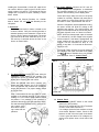
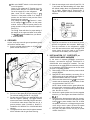
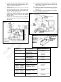
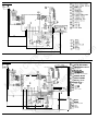
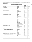
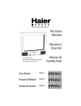
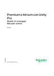
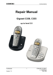
TOTROUBLESHOOT
ERRATIC CHECK LIGHT (GAS)
on AMES/AES Refrigerators
with 2931842XXX &
2931843XxX Power Modules
8)
Dometic@
REFRIGERATOR
BULLETIN R70/4B
March 1995
INTRODUCTION
M
N an
or ua
th l
Pr
w Co
e
i
st m
ht nte
tp d
R plim
V
:// F
en
w ro
S
w m
up ts
w
pl o
.n
y f
w
rv
su
pp
ly
.c
om
The purpose of this Bulletin is to aid the servicer in proper diagnosis and repair of AMEW/AES refrigerators. This
Bulletin will provide the servicer with information to find the hidden variables that can cause an erratic check light
when the refrigerator is operating on gas.
PARTS AND TOOLS REQUIRED:
/ r/ QUICK-CHECK TROUBLESHOOTING LIST
PAL@ Tester
Millivolt Meter
Volt-Ohm Meter
Manometer/Gas Pressure Gauge
Pliers & Screwdrivers
3108702.675 Kit, Wire Harness 7, 11 & 12 Series,
Silhouette S15XX, S16XX, S18XX Series
3108702.683 Kit, Wire Harness RM7030 & RM7130
1. DC Power Supply
2. Gas Supply
3. Components:
A.
B.
C.
D.
Thermocouple
Burner
Reignitor
Electrode
E. Solenoid
F. Power Module
G. Control Panel
4. Grounds
5. Installation of 3108702.675 or 3108702.683
Wire Harness Kit
DETAILED TROUBLESHOOTING LIST
1. DC POWER SUPPLY
Clean Direct Current (DC) power is mandatory for hightech circuits to operate as designed. The sources for DC
power are a battery and a converter.
A battery will provide straight line DC power, but extended
operation will require recharging of the battery by the
converter or the alternator.
The converter and alternator produce DC power by a series
of diodes that rectify alternating current to DC. A battery or
capacitors can be used to clean up the AC ripple that is
present after AC voltage has been rectified.
AC ripple can be measured by a digital voltmeter set on the
AC scale at the main terminal block connections. Six volts
AC or less is acceptable. See FIG. 1.
A brief interruption of the DC power supply while refrigerator is operating on gas can cause a check light; for
example:
Turning the refrigerator OFF-ON while operating in
the gas mode can cause a check light. The switching
of relays from converter power to battery power when
unplugging from shore power or shutting down of the
generator could interrupt DC power long enough to
cause a check light.
The thermocouple produces 25-30 MVDC when operating. When DC power is interrupted and restored, the
thermocouple may not have sufficient time to cool. If the
power module sees above 6 MVDC, when power is
restored the power module will assume a problem in the
gas mode and immediately turn on the check light.
MAIN TERMINAL BLOCK
FIG. 1
Form No. 3106465.002 4/95
Copyright 1995 The Dometic Corp.
LaGrange, IN 46761
2. GAS SUPPLY
C.
The refrigerator requires 11 inches water column with half
of all the BTU’s of the RV turned on (half of all aDubances
turned on). With all the appliances off, the pressure to the
refrigerator should not exceed 12 inches water column.
The gas pressure for the refrigerator is taken at the test port
after the solenoid with the refrigerator operating. See FIG.
2 & 2A.
THERMOCOUPLE
Verify proper DC power is at the positive (+) and
ground (-) terminals. The reading should be within
one volt of the voltage at the main terminal block
during the trial-for-ignition. (See Item 4, Grounds,
Paragraph E).
I
M
N an
or ua
th l
Pr
w Co
e
i
st m
ht nte
tp d
R plim
V
:// F
en
w ro
S
w m
up ts
w
pl o
.n
y f
w
rv
su
pp
ly
.c
om
FIG. 2 SlLHOUETTE
The Reignitor is an electronic device that produces high voltage to create a spark to ignite a
flame at the burner, when refrigerator operates on
LP gas.
I
FIG. 2A
DOMETIC
SOLENOID VALVE
BURNER WITH
THERMOCOUPLE
The reignitor installed on the refrigerators as
original equipment is part number 2931132019
(RV Gas Model 679). This reignitor is rated 50
MA. This reignitor may also be used on any other
model.
DO NOT install the Channel Mark 6, Model 12E
Reignitor (shown below) as a service replacement part. (FIG. 3 & 3A).
Board
FIG. 3
3. COMPONENTS
A. The Thermocouple is a component that extends
over three slots on the burner assembly so its tip
is in the path of the flame. During normal gas
operation, the thermocouple should produce 25 to
30 millivolts when connected to the lower circuit
board. Any reading below 18 millivolts could cause
erratic gas operation. NOTE: A reading of 18 or
less could be caused by low gas pressure or
improper thermocouple location.The thermocouple
should be centered over the burner and extend over
3 slots. See FIG. 2 & 2A.
B. The Burner is a horizontal slotted metal tube
located below the flue tube of the cooling unit. The
burner should be cleaned periodically (at least
once a year). To clean the burner, remove from
the refrigerator and check for any foreign residue
(rust, spider webs, etc.) that could cause a deflection of the gas flow or flame. Soak the burner in an
alcohol based solvent and allow to air dry. Reinstall in refrigerator and leak check all gas connections with an approved leak check solution. See
FIG. 2 & 2A. ’ ’
GASLllER
MARK 6, MODEL 12E
W/O 1282150 9318
12VDC 2 5 m A
CHANNEL PRODUCTS
CHESTERLAND OH 44026
2
F. The Power Module monitors the DC and AC
power supplied to the refrigerator. It coordinates
the operation between DC, AC and gas in conjunction with the setting of the display panel.
Installing the Channel Mark 6, Model 12E, rated 25 MA
can result in failure to ignite on gas if the DC power
supply is below 12.5 volts DC. The reignitor will see low
voltage and not produce a spark, resulting in flame
failure lockout.
Check the fuse(s) under the cover on the power
module for continuity. Replace with same size if
bad. Inspect for a loose relay and Plug 3 (P3) on
the board. If loose, replace board. See FIG. 6.
Installation of the Channel Products, Inc., Gasliter
Mark 6, Model 12E, will VOID the Warranty on the
refrigerator.
When the refrigerator requires additional cooling,
the power module will send DC voltage to the
solenoid and reignitor. The trial-for-ignition will
last for 45 seconds and at the end of this period,
the check light will come on if there is no flame.
NOTE: When the thermocouple output is between
7-l 3 millivolts DC, the DC voltage to the reignitor
will be turned off. If the flame is extinguished, the
power module will not supply DC power to the
reignitor until the millivolts DC drop to 7-13
MVDC. It may take 1 O-l 5 seconds for the thermocouple to cool.
M
N an
or ua
th l
Pr
w Co
e
i
st m
ht nte
tp d
R plim
V
:// F
en
w ro
S
w m
up ts
w
pl o
.n
y f
w
rv
su
pp
ly
.c
om
D. Electrode
First, do a visual check for cracks or breaks on the
ceramic insulator. Verify the mounting bracket is
attached properly to the electrode. If either of the
above is found, replace the electrode. The spark
gap must be set at three sixteenths (3/16”) of an
inch and tip of electrode above the slots in the
burner as shown below.
The PAL@ Tester will allow for proper testing of
the integrity of the upper and lower circuit cards.
The PAL@ Tester is available from your Dometic
parts distributor. See “G. Control Panel”.
ELECTRODE
I
BURN
E.
FIG. 6
P1
P3
The Solenoid Valve receives DC power when the
AMES/AES control selects LP gas operation. The
solenoid coil opens an internal valve seat and
allows gas to follow to the main orifice.
Check the solenoid valve with a properly calibrated ohm meter. Remove one of the connectors
from the solenoid and measure the resistance
across the terminals. The proper reading would
be 44-53 ohms.
Hook a manometerto the test port. With DC power
supplied to the solenoid terminals, a gas pressure
reading of 11-12 inches of water column should
be present. If no pressure or low pressure is
present at the test port, the gas solenoid is defective and should be replaced. NOTE: Verify the LP
gas system pressure before replacing a valve with low
pressure.
G. Control Panel
1) With the main ON/OFF switch on the control
panel in the OFF position:
Check for DC voltage at Plug 1 (P1) Terminal 4
of lower circuit board. See FIG. 6.
If no voltage, check the fuse condition on lower
circuit board. Replace if blown. Check for DC
between J4 and J10 on the lower circuit board.
If fuse is good and there is DC voltage at J4,
remove and replace lower circuit board. See
FIG. 6.
3
With main ON/OFF switch on the control panel
in the ON position:
Check for DC voltage at P1 Terminal 4 on the
power module. See FIG. 6. It should be within +l
volt of the supply DC to the refrigerator.
Next, check for DC voltage at Plug 1 (Pl)
Terminal 1 of the power module. If no voltage is
present, then the switch is faulty and the control
panel should be replaced.
If DC voltage is present at Pl Terminal 1, check
for DC voltage on Pl Terminal 3 on the power
module. If there is NO DC power present, the
power module is faulty and should be replaced.
See FIG. 6.
E.
Shut the manual gas cock valve off (see FIG. 5 &
7) and watch the millivolt reading as it drops. Note
the millivolt reading when the reignitorstarts sparking (7-13MV). Repeat Step E several times. If
reignitor fails to spark or sparks continuously, it is
defective.
FIG. 5
MANUAL
GAS COCK
VALVE
M
N an
or ua
th l
Pr
w Co
e
i
st m
ht nte
tp d
R plim
V
:// F
en
w ro
S
w m
up ts
w
pl o
.n
y f
w
rv
su
pp
ly
.c
om
2)
The PAL@ Tester will allow for proper testing of
the integrity of the upper and lower circuit cards.
The PALmTester is available from your Dometic Parts Distributor.
4. GROUNDS
A quick, easy way to test for ground problems can be
done with a millivolt meter.
A. Connect a digital millivolt meter to J3 and JlO of
power module. See FIG. 4
F.
Check all connections on the 6-terminal ground
bus bar for tightness and corrosion. Make sure
that the connection to the refrigerator’s 4-pole
main DC terminal block are clean and tight. The
same checks should be made to the coach’s
connection at the battery and converter.
FIG. 4
5. INSTALLATION OF 3108702.675 or
3108702.683 WIRE HARNESS
In the event of repeated checklight occurrences,
Dometic recommends that the 3108702.675 or
3108702.683 wire harness be installed. The wire
harness serves as a precaution to lessen the possibility of intermittent check lights which can be the result
of loose or corroded grounds.
A. Remove the covers from both the power module
and the reignitor.
B. Remove the cable assembly connecting P3 on
power module to the gas solenoid and reignitor. It
can be discarded. See FIG. 6 and 6A.
C. Disconnect the white wire from JlO on the power
module and the 6-terminal ground bus bar. It also
can be discarded. See FIG. 6 & 7.
NOTE: Some models have the green/yellow wire
from the ignitor connected in with the terminal on
the white wire. It is removed along with the white
wire. See FIG. 6, 6A & 7.
D. Remove the green/yellow wire from the negative
terminal (-) on the reignitor and discard. See FIG.
6A&7.
E. Disconnect the thermocouple lead from 6-terminal ground bus bar. Reconnect the thermocouple
lead to JlO on power module. See FIG. 6. Bend
the spade connector to a 45 degree angle so the
cover will go back in place. Be sure the spade
connector does not contact AC terminal at J8.
F. Plug the new cable into the P3 plug on power
module. See FIG. 6.
Main Terminal Block
B. Pull one of the wires off the gas solenoid valve.
The millivolt reading should be 1-2 or less.
C. Put the wire back on the gas solenoid valve and
with the reignitor sparking, the digital millivolt
meter should read 5 millivolts or less at this time.
If the millivolt meter shows more than six (6), a
ground problem exists. Proceed to Section 5,
Installation of 3108702.675 or 3108702.683 Wire
Harness.
D. The digital millivolt meter should register between
25-30 millivolts with the gas flame burning.
4
Inspect wiring to make sure it is not shorting to
other wires or components. Replace reignitor and
power module covers.
Choose the correct wiring diagram from the Chart
below and install it over the old wiring diagram.
See FIG. 8.
Test operation of the refrigerator per the Installation and Operating Manual.
FIG. 7
REMOVE ORIGINAL WHITE AND
CONNECT 2
\ -
M
N an
or ua
th l
Pr
w Co
e
i
st m
ht nte
tp d
R plim
V
:// F
en
w ro
S
w m
up ts
w
pl o
.n
y f
w
rv
su
pp
ly
.c
om
G. Connect the end of the white wire from P3 (two
white wires spliced into spade terminal) to the 6terminal ground bus. See FIG. 7.
H. Connect the remaining white wire to the gas
solenoid valve.
I. Connect the yellow wire from P3 (two yellow wires
spliced into spade terminal) to the remaining terminal on the gas solenoid valve.
J. Connect the remaining yellow wire with smaller
spade terminal to the (+) terminal on the reigniter.
See FIG. 6A & 7.
K. Connect the new black wire to the 6-terminal
ground bus and the (-) terminal on the reigniter.
See FIG. 6A.
FIG. 6
P3
Pl
ITE WIRES FROM
P3 TO S-TERMINAL GROUND BUS BAR
AMP
FUSE
FIG. 6A
STEP B
/ Remove Blue wire
35 AMP
FUSE
Black wire
W
FIG. 6
MODELS
DESCRIPTION
1 WIRING DIAGRAM NO.
S1621, S1821
Silhouette 6 & 8 cu. ft.
AMES 2-Way
I
S1631,S1831
Silhouette 6 & 8 cu. ft.
AMES 3-Way
s1521
Silhouette 5 cu. ft.
AMES 2-Way
2931895
s1531
Silhouette 5 cu. ft.
AMES 3-Way
2931896
RM7030, RM7130
Dometic 10 cu. ft.
2932156
RM2607, RM2807
RM2611, RM2811
RM3607, RM3807
Dometic 6 & 8 cu. ft.
AMES/AES 2-Way
RM2607, RM2807
RM2611, RM2811
RM3607, RM3807
Dometic 6 & 8 cu. ft.
AMES/AES 3-Way
RM2612, RM2812
Dometic 6 & 8 cu. ft.
12 Series
5
2931878
M
N an
or ua
th l
Pr
w Co
e
i
st m
ht nte
tp d
R plim
V
:// F
en
w ro
S
w m
up ts
w
pl o
.n
y f
w
rv
su
pp
ly
.c
om
120 V O L T S A C
d
12 VOLTS DC
*@
120 VOLTS AC
c3--@
@@
E:it\‘A BsooAARRpD 'DqYiFAv
THERMISTOR
GAS VALVE
REIGNITEI?
THERMOCWPLE
o- E L E C T R O D E
@ RETAINER FOR BURNER
*@ :riAAALL
BSLTDRLz
Z@ ;;;;:;;;to”v
“ANdT
@ H E A T E R 1ZV D C
@--- F U S E 3 A
@ F U S E 5A
* SWITCH
@ LIGHT
@-- T E S T P O I N T
I
I
III
1
I
I
l **-
1zv D C
*@
:x
@-- G R E E N
@ GREEN/YELLOW
@--- G R E V
@ BROWN
a- Y E L L O W
-@
@---
120 VOLTS AC
@
@--@
@-@
@@
w
@
@@
u.-L=Y
VY
.-me.
I
M
N an
or ua
th l
Pr
w Co
e
i
st m
ht nte
tp d
R plim
V
:// F
en
w ro
S
w m
up ts
w
pl o
.n
y f
w
rv
su
pp
ly
.c
om
@---
%::TT it?:0 ::;:AY
THERMISTOR
GAS VALVE
RE IGNITER
THERMOCOUPLE
ELECTROOE
R E T A I N E R FCf7 B U R N E R
TERMINAL BLOCK
TERMINAL STRIP
A B S O R P T I O N UNIT
F U S E JA
FUSE 5A
HEATER 120V AC
TEST POINT
@-
WHITE
@ BLACK
@-- G R E E N
33 G R E E N / Y E L L O W
@-- G R E Y
@ YELLOW
?93
16
96
5
CIRCUIT BOARD POWER
CIRCUIT BOARD DISPLAY
THERMISTOR
GAS VALVE
REIGNITER
THERMOCOUPLE
12 VOLTS DC_
120 VOLTS
AC
ELECTRODE,
RETAINER FOR BURNER
TERMINAL BLOCK
TERMINAL STRIP
ABSORPTION UNIT
F U S E JA
FUSE 5A
H E A T E R 12OV A C
FUSE 35A
H E A T E R 12V D C
TEST POINT
1zv D C
00 WH’TE
I
2
@4
@--@
0
BLACK
GREEN
GREEN/YELLOW
GREY
YELLOW
293 2 1 56 1 2
&@.+
ABSORPTION
UNIT
TERMINAL BLOCK
M
N an
or ua
th l
Pr
w Co
e
i
st m
ht nte
tp d
R plim
V
:// F
en
w ro
S
w m
up ts
w
pl o
.n
y f
w
rv
su
pp
ly
.c
om
RETAINER FOR
CIRCUIT BOARD
E@ T E S T P O I N T
POWER
CHASSIS GROUND
Ilr---1
i
93 21 77-001 3 1
120 VOLTS AC
CIRCUIT BOARD POWER
CIRCUIT BOARD DISPLAY
THERMISTOR
GAS VALVE
REIGNITER
THERMOCOUPLE
ELECTRODE
RETAINER F O R B U R N E R
TERMINAL BLOCK
T E R M I N.\L SIR I P
ABSORPTION UNIT
H E A T E R 12OV A C
LIGHT
SW ITCH
F U S E JA
F U S E 5A
HEATING CABLE
SW I TCH
TERMINAL BLOCK
TERMINAL BLOCK
TEST POINT
.
I
Y
w
I
I
I
II
It-l-l-+
CIRCUIT BOARD POWER
CIRCUIT BOARD DISPLAY
THERMISTOR
GAS VALVE
RE IGNITER
THERM0C0UPLE
ELECTRODE
RETAINER fC+? BURNER
TERMINAL BLOCK
TERMINAL STRIP
ABSORPTION UNIT
HEATER 12OV AC
HEATER 12V DC
LIGHT
SWITCH
FUSE 3A
FUSE 5A
M
N an
or ua
th l
Pr
w Co
e
i
st m
ht nte
tp d
R plim
V
:// F
en
w ro
S
w m
up ts
w
pl o
.n
y f
w
rv
su
pp
ly
.c
om
FUSE J5A
HEATING CABLE
SWITCH
TERMINAL BLOCK
TERMINAL B L O C K
TEST
POINT
WHITE
BLACK
GREEN
GREEN/YELLOW
GREY
BROWN
BLUE
YELLOW
-9, 21 IICMO~ 2 j
120 VOLTS AC
0
@- CIRCUIT BOARD POWER
@ CIRCUIT BOARD DISPLAY
o- THERMISTOR
@j SOLENOID VALVE
@-- RE IGNITER
3 0 THERMOCOUPLE
ELECTRODE.
RETAINER FOR BURNER
TERMINAL BLOCK
0 T E R M I N A L S T R I P . GRWN(I
ABSORPTION UNIT
*@ HEATER 120V AC
FUSE JA
3 FUSE 5A
HEATING CABLE
a---- 8 SW ITCH
TERMINAL BLOCK
TEST POINT
0
BLACK
BROWN
RED
ORANGE
YELLOW
GREEN/YELLOW
w tJL”C
@- GREY
@ WHITE
M
N an
or ua
th l
Pr
w Co
e
i
st m
ht nte
tp d
R plim
V
:// F
en
w ro
S
w m
up ts
w
pl o
.n
y f
w
rv
su
pp
ly
.c
om
This Manual is Compliments of
Northwest RV Supply
86325 College View Road
Eugene, OR 97405
Local: 541-746-9092
Toll-Free: 866-678-7467
Fax: 541-736-5573
http://www.nwrvsupply.com
[email protected]
Northwest RV Supply carries a large spectrum of surplus, used, and new
RV parts and components. Please feel free to visit our website for
additional information.