
1
MediaPack SIP User’s Manual Version 4.6 Document #: LTRT-65405 Notice This document describes the AudioCodes MediaPack series Voice over IP (VoIP) gateways. Information contained in this document is believed to be accurate and reliable at the time of printing. However, due to ongoing product improvements and revisions, AudioCodes cannot guarantee accuracy of printed material after the Date Published nor can it accept responsibility for errors or omissions. Updates to this document and other documents can be viewed by registered Technical Support customers at www.audiocodes.com under Support / Product Documentation. © Copyright 2005 AudioCodes Ltd. All rights reserved. This document is subject to change without notice. Date Published: Jul-13-2005 Date Printed: Jul-27-2005 MediaPack SIP User’s Manual Contents Table of Contents 1 Overview ....................................................................................................................17 1.1 1.2 1.3 1.4 2 Introduction .....................................................................................................................................17 Gateway Description.......................................................................................................................17 SIP Overview ..................................................................................................................................18 MediaPack Features.......................................................................................................................19 1.4.1 General Features ....................................................................................................................19 1.4.2 MP-1xx Hardware Features ....................................................................................................19 1.4.3 MP-11x Hardware Features....................................................................................................19 1.4.4 SIP Features ...........................................................................................................................20 MediaPack Physical Description..............................................................................23 2.1 MP-1xx Physical Description ..........................................................................................................23 2.1.1 MP-1xx Front Panel ................................................................................................................23 2.1.1.1 MP-1xx Front Panel Buttons.........................................................................................24 2.1.1.2 MP-1xx Front Panel LEDs ............................................................................................24 2.1.2 MP-1xx Rear Panel.................................................................................................................25 2.1.2.1 MP-10x Rear Panel ......................................................................................................25 2.1.2.2 MP-124 Rear Panel ......................................................................................................26 2.2 MP-11x Physical Description..........................................................................................................27 2.2.1 MP-11x Front Panel ................................................................................................................27 2.2.2 MP-11x Rear Panel.................................................................................................................28 3 Installing the MediaPack...........................................................................................29 3.1 Installing the MP-1xx ......................................................................................................................29 3.1.1 Unpacking ...............................................................................................................................29 3.1.1.1 Package Contents ........................................................................................................29 3.1.2 Mounting the MP-1xx ..............................................................................................................30 3.1.2.1 Mounting the MP-1xx on a Desktop .............................................................................30 3.1.2.2 Installing the MP-10x in a 19-inch Rack .......................................................................30 3.1.2.3 Installing the MP-124 in a 19-inch Rack .......................................................................31 3.1.2.4 Mounting the MP-10x on a Wall ...................................................................................32 3.1.3 Cabling the MP-1xx.................................................................................................................33 3.1.3.1 Connecting the MP-1xx RS-232 Port to Your PC.........................................................35 3.1.3.2 Cabling the Lifeline Phone............................................................................................35 3.2 Installing the MP-11x ......................................................................................................................38 3.2.1 Unpacking ...............................................................................................................................38 3.2.2 Package Contents...................................................................................................................38 3.2.3 19-inch Rack Installation Package..........................................................................................39 3.2.4 Mounting the MP-11x..............................................................................................................39 3.2.4.1 Mounting the MP-11x on a Desktop .............................................................................40 3.2.4.2 Mounting the MP-11x on a Wall ...................................................................................40 3.2.4.3 Installing the MP-11x in a 19-inch Rack .......................................................................40 3.2.5 Cabling the MP-11x ................................................................................................................41 3.2.5.1 Connecting the MP-11x RS-232 Port to Your PC ........................................................41 3.2.5.2 Cabling the MP-11x Lifeline..........................................................................................42 4 Getting Started...........................................................................................................43 4.1 4.2 Configuration Concepts ..................................................................................................................43 Assigning the MediaPack IP Address.............................................................................................43 4.2.1 Assigning an IP Address Using HTTP ....................................................................................44 4.2.2 Assigning an IP Address Using BootP....................................................................................44 4.3 Configure the MediaPack Basic Parameters..................................................................................45 5 Configuring the MediaPack ......................................................................................47 5.1 5.2 Computer Requirements.................................................................................................................47 Protection and Security Mechanisms .............................................................................................47 5.2.1 Dual Access Level Username and Password.........................................................................47 5.2.2 Limiting the Embedded Web Server to Read-Only Mode.......................................................48 Version 4.6 3 June 2005 MediaPack SIP 5.2.3 Disabling the Embedded Web Server.....................................................................................48 Accessing the Embedded Web Server...........................................................................................48 5.3.1 Using Internet Explorer to Access the Embedded Web Server..............................................49 5.4 Getting Acquainted with the Web Interface ....................................................................................49 5.4.1 Main Menu Bar........................................................................................................................50 5.4.2 Saving Changes......................................................................................................................50 5.4.3 Entering Phone Numbers in Various Tables...........................................................................50 5.5 Protocol Management.....................................................................................................................51 5.5.1 Protocol Definition Parameters ...............................................................................................51 5.5.1.1 General Parameters .....................................................................................................51 5.5.1.2 Proxy & Registration Parameters .................................................................................56 5.5.1.3 Coders ..........................................................................................................................61 5.5.1.4 DTMF & Dialing Parameters.........................................................................................63 5.5.2 Configuring the Advanced Parameters...................................................................................66 5.5.2.1 General Parameters .....................................................................................................66 5.5.2.2 Supplementary Services...............................................................................................71 5.5.2.3 Keypad Features ..........................................................................................................74 5.5.3 Configuring the Number Manipulation Tables ........................................................................76 5.5.3.1 Dialing Plan Notation ....................................................................................................79 5.5.4 Configuring the Routing Tables ..............................................................................................81 5.5.4.1 General Parameters .....................................................................................................81 5.5.4.2 Tel to IP Routing Table .................................................................................................83 5.5.4.3 IP to Hunt Group Routing .............................................................................................86 5.5.4.4 Internal DNS Table .......................................................................................................88 5.5.4.5 Reasons for Alternative Routing...................................................................................89 5.5.5 Configuring the Profile Definitions ..........................................................................................91 5.5.5.1 Coder Group Settings ...................................................................................................91 5.5.5.2 Tel Profile Settings........................................................................................................93 5.5.5.3 IP Profile Settings .........................................................................................................95 5.5.6 Configuring the Endpoint Phone Numbers .............................................................................97 5.5.7 Configuring the Hunt Group Settings......................................................................................99 5.5.8 Configuring the Endpoint Settings ........................................................................................101 5.5.8.1 Authentication .............................................................................................................101 5.5.8.2 Automatic Dialing........................................................................................................102 5.5.8.3 Caller ID ......................................................................................................................103 5.5.8.4 Generate Caller ID to Tel............................................................................................104 5.5.8.5 Call Forward ...............................................................................................................105 5.5.9 Configuring the FXO Parameters..........................................................................................107 5.5.10 Configuring the Voice Mail (VM) Parameters .......................................................................109 5.5.11 Protocol Management ini File Parameters............................................................................111 5.6 Advanced Configuration ...............................................................................................................114 5.6.1 Configuring the Network Settings .........................................................................................114 5.6.1.1 Configuring the IP Settings .........................................................................................114 5.6.1.2 Configuring the Application Settings...........................................................................117 5.6.1.3 Configuring the SNMP Managers Table.....................................................................119 5.6.1.4 Configuring the Web and Telnet Access List..............................................................120 5.6.1.5 Configuring the RTP Settings .....................................................................................121 5.6.1.6 Configuring the IP Routing Table ...............................................................................123 5.6.1.7 Viewing the Ethernet Port Information........................................................................124 5.6.1.8 Configuring the VLAN Settings...................................................................................125 5.6.1.9 Configuring the Security Settings (MP-11x Only) .......................................................127 5.6.1.10 Advanced Configuration ini File Parameters ..............................................................128 5.6.1.11 Automatic Updates Parameters..................................................................................132 5.6.1.12 SNMP ini File Parameters ..........................................................................................133 5.6.2 Configuring the Channel Settings .........................................................................................134 5.6.2.1 Configuring the Voice Settings ...................................................................................134 5.6.2.2 Configuring the Fax / Modem / CID Settings ..............................................................136 5.6.2.3 Configuring the RTP Settings .....................................................................................139 5.6.2.4 Configuring the Hook-Flash Settings..........................................................................141 5.6.2.5 Channel Settings ini File Parameters .........................................................................141 5.6.3 Restoring and Backing up the Gateway Configuration.........................................................144 5.6.4 Regional Settings..................................................................................................................145 5.3 MediaPack SIP User’s Manual 4 Document #: LTRT-65405 MediaPack SIP User’s Manual Contents 5.6.5 Changing the MediaPack Username and Password ............................................................146 Status & Diagnostics.....................................................................................................................147 5.7.1 Gateway Statistics ................................................................................................................147 5.7.1.1 IP Connectivity............................................................................................................147 5.7.1.2 Call Counters ..............................................................................................................148 5.7.1.3 Call Routing Status .....................................................................................................150 5.7.2 Monitoring the MediaPack Channels ....................................................................................151 5.7.3 Activating the Internal Syslog Viewer ...................................................................................153 5.7.4 Device Information ................................................................................................................154 5.8 Software Update ...........................................................................................................................155 5.8.1 Software Upgrade Wizard.....................................................................................................155 5.8.2 Auxiliary Files ........................................................................................................................159 5.8.2.1 Loading the Auxiliary Files via the ini File...................................................................160 5.9 Save Configuration .......................................................................................................................161 5.10 Resetting the MediaPack..............................................................................................................162 5.7 6 ini File Configuration of the MediaPack ................................................................ 163 6.1 6.2 6.3 7 Using BootP / DHCP................................................................................................ 165 7.1 7.2 7.3 8 Secured ini File .............................................................................................................................163 Modifying an ini File ......................................................................................................................163 The ini File Structure.....................................................................................................................164 6.3.1 The ini File Structure Rules...................................................................................................164 6.3.2 The ini File Example .............................................................................................................164 BootP/DHCP Server Parameters .................................................................................................165 Using DHCP .................................................................................................................................165 Using BootP..................................................................................................................................166 7.3.1 Upgrading the MediaPack.....................................................................................................166 7.3.2 Vendor Specific Information Field .........................................................................................167 Telephony Capabilities ........................................................................................... 169 8.1 Working with Supplementary Services .........................................................................................169 8.1.1 Call Hold and Retrieve ..........................................................................................................169 8.1.1.1 Initiating Hold/Retrieve................................................................................................169 8.1.1.2 Receiving Hold / Retrieve ...........................................................................................169 8.1.2 Consultation / Alternate.........................................................................................................169 8.1.3 Call Transfer..........................................................................................................................170 8.1.4 Call Forward..........................................................................................................................170 8.1.5 Call Waiting ...........................................................................................................................171 8.1.6 Message Waiting Indication ..................................................................................................171 8.2 Configuring the DTMF Transport Types .......................................................................................173 8.3 Fax & Modem Transport Modes ...................................................................................................176 8.3.1 Fax/Modem Settings .............................................................................................................176 8.3.2 Configuring Fax Relay Mode ................................................................................................176 8.3.3 Configuring Fax/Modem Bypass Mode.................................................................................176 8.3.4 Supporting V.34 Faxes .........................................................................................................177 8.3.4.1 Using Bypass Mechanism for V.34 Fax Transmission ...............................................177 8.3.4.2 Using Relay mode for both T.30 and V.34 faxes........................................................177 8.4 Call Termination on MediaPack/FXO ...........................................................................................177 8.5 ThroughPacket™..........................................................................................................................178 8.6 Dynamic Jitter Buffer Operation ...................................................................................................178 8.7 Configuring the Gateway’s Alternative Routing (based on Connectivity and QoS)......................179 8.7.1 Alternative Routing Mechanism ............................................................................................179 8.7.2 Determining the Availability of Destination IP Addresses.....................................................180 8.7.3 Relevant Parameters ............................................................................................................180 8.8 Mapping PSTN Release Cause to SIP Response .......................................................................180 8.9 Call Detail Report..........................................................................................................................181 8.10 Proxy or Registrar Registration Example .....................................................................................182 8.11 Configuration Examples................................................................................................................183 8.11.1 Establishing a Call between Two Gateways.........................................................................183 8.11.2 SIP Call Flow.........................................................................................................................184 8.11.3 SIP Authentication Example .................................................................................................187 Version 4.6 5 June 2005 MediaPack SIP 8.11.4 Remote IP Extension between FXO and FXS ......................................................................189 8.11.4.1 Dialing from Remote Extension ..................................................................................189 8.11.4.2 Dialing from other PBX line, or from PSTN ................................................................190 8.11.4.3 FXS MediaPack Configuration (using the Embedded Web Server)...........................190 8.11.4.4 FXO MediaPack Configuration (using the Embedded Web Server) ..........................191 9 Networking Capabilities.......................................................................................... 193 9.1 9.2 9.3 9.4 9.5 9.6 Ethernet Interface Configuration...................................................................................................193 NAT (Network Address Translation) Support ...............................................................................193 Robust Reception of RTP Streams ..............................................................................................194 Multiple Routers Support ..............................................................................................................194 Simple Network Time Protocol Support........................................................................................194 VLANS and Multiple IPs ...............................................................................................................196 9.6.1 Multiple IPs............................................................................................................................196 9.6.2 IEEE 802.1p/Q (VLANs and Priority) ....................................................................................196 9.6.2.1 Operation ....................................................................................................................197 9.6.3 Getting Started with VLANS and Multiple IPs.......................................................................197 9.6.3.1 Integrating Using the Embedded Web Server ............................................................198 9.6.3.2 Integrating Using the ini File .......................................................................................200 10 Advanced System Capabilities .............................................................................. 201 10.1 Restoring Networking Parameters to their Initial State.................................................................201 10.2 Establishing a Serial Communications Link with the MediaPack .................................................201 10.3 Automatic Update Mechanism......................................................................................................202 10.4 Startup Process ............................................................................................................................204 10.5 Customizing the MediaPack Web Interface..................................................................................206 10.5.1 Replacing the Main Corporate Logo .....................................................................................206 10.5.1.1 Replacing the Main Corporate Logo with an Image File ............................................206 10.5.1.2 Replacing the Main Corporate Logo with a Text String..............................................208 10.5.2 Replacing the Background Image File..................................................................................208 10.5.3 Customizing the Product Name ............................................................................................209 10.5.4 Modifying ini File Parameters via the Web AdminPage........................................................210 11 Special Applications ............................................................................................... 211 11.1 Metering Tones Relay...................................................................................................................211 12 Security (MP-11x Only) ........................................................................................... 213 12.1 SSL/TLS (MP-11x Only) ...............................................................................................................213 12.1.1 SIP Over TLS (SIPS) ............................................................................................................213 12.1.2 Embedded Web Server Configuration ..................................................................................213 12.1.2.1 Using the Secured Embedded Web Server................................................................214 12.1.3 Secured Telnet......................................................................................................................214 12.1.4 Server Certificate Replacement ............................................................................................214 12.1.5 Client Certificates..................................................................................................................216 12.2 RADIUS Login Authentication (MP-11x Only) ..............................................................................217 12.2.1 Setting Up a RADIUS Server ................................................................................................217 12.2.2 Configuring RADIUS Support ...............................................................................................218 12.3 Network Port Usage......................................................................................................................219 12.4 Recommended Practices..............................................................................................................219 12.5 Legal Notice..................................................................................................................................220 13 Diagnostics .............................................................................................................. 221 13.1 Self-Testing...................................................................................................................................221 13.2 Syslog Support .............................................................................................................................222 13.2.1 Syslog Servers ......................................................................................................................222 13.2.2 Operation ..............................................................................................................................222 14 Embedded Command Line Interface ..................................................................... 223 14.1 Accessing the CLI.........................................................................................................................223 14.2 Using the CLI ................................................................................................................................224 14.2.1 Changing the Networking Parameters..................................................................................225 MediaPack SIP User’s Manual 6 Document #: LTRT-65405 MediaPack SIP User’s Manual Contents 15 SNMP-Based Management ..................................................................................... 227 15.1 About SNMP .................................................................................................................................227 15.1.1 SNMP Message Standard ....................................................................................................227 15.1.2 SNMP MIB Objects ...............................................................................................................228 15.1.3 SNMP Extensibility Feature ..................................................................................................228 15.2 Carrier Grade Alarm System ........................................................................................................229 15.2.1 Active Alarm Table................................................................................................................229 15.2.2 Alarm History.........................................................................................................................229 15.3 Cold Start Trap .............................................................................................................................229 15.4 Third-Party Performance Monitoring Measurements ...................................................................230 15.5 Supported MIBs ............................................................................................................................231 15.6 Traps.............................................................................................................................................232 15.7 SNMP Interface Details ................................................................................................................233 15.7.1 SNMP Community Names ....................................................................................................233 15.7.1.1 Configuration of Community Strings via the ini File....................................................233 15.7.1.2 Configuration of Community Strings via SNMP..........................................................233 15.7.2 Trusted Managers.................................................................................................................235 15.7.2.1 Configuration of Trusted Managers via ini File ...........................................................235 15.7.2.2 Configuration of Trusted Managers via SNMP ...........................................................235 15.7.3 SNMP Ports ..........................................................................................................................236 15.7.4 Multiple SNMP Trap Destinations .........................................................................................236 15.7.4.1 Trap Manger Configuration via Host Name ................................................................236 15.7.4.2 Trap Managers Configuration via the ini File..............................................................237 15.7.4.3 Trap Mangers Configuration via SNMP......................................................................237 15.8 SNMP Manager Backward Compatibility......................................................................................239 15.9 AudioCodes’ Element Management System ................................................................................239 16 Configuration Files.................................................................................................. 241 16.1 Configuring the Call Progress Tones and Distinctive Ringing File...............................................241 16.1.1 Format of the Call Progress Tones Section in the ini File ....................................................241 16.1.2 Format of the Distinctive Ringing Section in the ini File .......................................................243 16.1.2.1 Examples of Various Ringing Signals.........................................................................245 16.2 Prerecorded Tones (PRT) File .....................................................................................................246 16.2.1 PRT File Format....................................................................................................................246 16.3 The Coefficient Configuration File ................................................................................................247 17 Selected Technical Specifications ......................................................................... 249 17.1 MP-1xx Specifications ..................................................................................................................249 17.2 MP-11x Specifications ..................................................................................................................251 Appendix A MediaPack SIP Software Kit................................................................. 255 Appendix B The BootP/TFTP Configuration Utility................................................. 257 B.1 When to Use the BootP/TFTP ......................................................................................................257 B.2 An Overview of BootP...................................................................................................................257 B.3 Key Features ................................................................................................................................257 B.4 Specifications................................................................................................................................258 B.5 Installation.....................................................................................................................................258 B.6 Loading the cmp File, Booting the Device ....................................................................................258 B.7 BootP/TFTP Application User Interface........................................................................................259 B.8 Function Buttons on the Main Screen ..........................................................................................259 B.9 Log Window ..................................................................................................................................260 B.10 Setting the Preferences ................................................................................................................261 B.10.1 BootP Preferences................................................................................................................261 B.10.2 TFTP Preferences.................................................................................................................262 B.11 Configuring the BootP Clients ......................................................................................................263 B.11.1 Adding Clients .......................................................................................................................263 B.11.2 Deleting Clients .....................................................................................................................264 B.11.3 Editing Client Parameters .....................................................................................................264 B.11.4 Testing the Client ..................................................................................................................264 B.11.5 Setting Client Parameters .....................................................................................................265 Version 4.6 7 June 2005 MediaPack SIP B.11.6 Using Command Line Switches ............................................................................................266 B.12 Managing Client Templates..........................................................................................................267 Appendix C C.1 C.2 C.3 RTP/RTCP Payload Types and Port Allocation .................................. 269 Packet Types Defined in RFC 3551 .............................................................................................269 Defined Payload Types.................................................................................................................269 Default RTP/RTCP/T.38 Port Allocation.......................................................................................270 Appendix D Accessory Programs and Tools .......................................................... 271 D.1 TrunkPack Downloadable Conversion Utility................................................................................271 D.1.1 Converting a CPT ini File to a Binary dat File.......................................................................272 D.1.2 Encoding / Decoding an ini File ............................................................................................273 D.1.3 Creating a Loadable Prerecorded Tones File.......................................................................274 D.2 Call Progress Tones Wizard .........................................................................................................276 D.2.1 About the Call Progress Tones Wizard.................................................................................276 D.2.2 Installation .............................................................................................................................276 D.2.3 Initial Settings........................................................................................................................276 D.2.4 Recording Screen – Automatic Mode ...................................................................................277 D.2.5 Recording Screen – Manual Mode .......................................................................................279 D.2.6 The Call Progress Tones ini File...........................................................................................279 Appendix E SNMP Traps........................................................................................... 281 E.1 Alarm Traps ..................................................................................................................................281 E.1.1 Component: Board#<n>........................................................................................................281 E.1.2 Component: AlarmManager#0..............................................................................................283 E.1.3 Component: EthernetLink#0 .................................................................................................283 E.1.4 Log Traps (Notifications).......................................................................................................284 E.1.5 Other Traps ...........................................................................................................................285 E.1.6 Trap Varbinds........................................................................................................................285 Appendix F F.1 F.2 F.3 F.4 Regulatory Information ........................................................................ 287 MP-1xx FXS..................................................................................................................................287 MP-1xx FXO .................................................................................................................................288 MP-124 .........................................................................................................................................290 MP-11x FXS .................................................................................................................................292 MediaPack SIP User’s Manual 8 Document #: LTRT-65405 MediaPack SIP User’s Manual Contents List of Figures Figure 1-1: Typical MediaPack VoIP Application .............................................................................................18 Figure 2-1: MP-108 Front Panel .......................................................................................................................23 Figure 2-2: MP-124 Front Panel .......................................................................................................................23 Figure 2-3: MP-104/FXS Rear Panel Connectors ............................................................................................25 Figure 2-4: MP-124 (FXS) Rear Panel Connectors..........................................................................................26 Figure 2-5: MP-118 Front Panel Connectors ...................................................................................................27 Figure 2-6: MP-118 Rear Panel Connectors ....................................................................................................28 Figure 3-1: Desktop or Shelf Mounting.............................................................................................................30 Figure 3-2: MP-108 with Brackets for Rack Installation ...................................................................................31 Figure 3-3: MP-124 with Brackets for Rack Installation ...................................................................................32 Figure 3-4: MP-102 Wall Mount........................................................................................................................32 Figure 3-5: RJ-45 Ethernet Connector Pinout ..................................................................................................33 Figure 3-6: RJ-11 Phone Connector Pinout .....................................................................................................34 Figure 3-7: 50-pin Telco Connector (MP-124/FXS only) ..................................................................................34 Figure 3-8: MP-124 in a 19-inch Rack with MDF Adaptor................................................................................34 Figure 3-9: MP-1xx RS-232 Cable Wiring ........................................................................................................35 Figure 3-10: Lifeline Splitter Pinout & RJ-11 Connector for MP-10x/FXS........................................................36 Figure 3-11: MP-104/FXS Lifeline Setup..........................................................................................................36 Figure 3-12: 19-inch Rack Shelf .......................................................................................................................39 Figure 3-13: View of the MP-11x Base.............................................................................................................39 Figure 3-14: MP-11x Rack Mount.....................................................................................................................40 Figure 3-15: RJ-45 Ethernet Connector Pinout ................................................................................................41 Figure 3-16: RJ-11 Phone Connector Pinout ...................................................................................................41 Figure 3-17: PS/2 Pinout ..................................................................................................................................41 Figure 3-18: Lifeline Splitter Pinout & RJ-11 Connector...................................................................................42 Figure 4-1: Quick Setup Screen .......................................................................................................................45 Figure 5-1: Embedded Web Server Login Screen ...........................................................................................48 Figure 5-2: MediaPack Web Interface ..............................................................................................................49 Figure 5-3: Protocol Definition, General Parameters Screen ...........................................................................51 Figure 5-4: Proxy & Registration Parameters Screen ......................................................................................56 Figure 5-5: Coders Screen ...............................................................................................................................61 Figure 5-6: DTMF & Dialing Parameters Screen..............................................................................................63 Figure 5-7: Advanced Parameters, General Parameters Screen ....................................................................66 Figure 5-8: Supplementary Services Parameters Screen ................................................................................71 Figure 5-9: Keypad Features Screen ...............................................................................................................74 Figure 5-10: Source Phone Number Manipulation Table for TelÆIP calls ......................................................76 Figure 5-11: Routing Tables, General Parameters Screen ..............................................................................81 Figure 5-12: Tel to IP Routing Table Screen....................................................................................................84 Figure 5-13: IP to Hunt Group Routing Table Screen ......................................................................................86 Figure 5-14: Internal DNS Table Screen ..........................................................................................................88 Figure 5-15: Reasons for Alternative Routing Screen......................................................................................89 Figure 5-16: Coder Group Settings Screen ......................................................................................................91 Figure 5-17: Tel Profile Settings Screen...........................................................................................................93 Figure 5-18: IP Profile Settings Screen ............................................................................................................95 Figure 5-19: Endpoint Phone Number Table Screen .......................................................................................97 Figure 5-20: Hunt Group Settings screen.........................................................................................................99 Figure 5-21: Authentication Screen ................................................................................................................101 Figure 5-22: Automatic Dialing Table Screen.................................................................................................102 Figure 5-23: Caller Display Information Screen .............................................................................................103 Figure 5-24: MediaPack FXS Generate Caller ID to Tel Screen....................................................................104 Figure 5-25: Call Forwarding Table Screen ...................................................................................................105 Figure 5-26: FXO Settings Screen .................................................................................................................107 Figure 5-27: Voice Mail Screen ......................................................................................................................109 Figure 5-28: IP Settings Screen .....................................................................................................................114 Figure 5-29: Application Settings Screen .......................................................................................................117 Figure 5-30: SNMP Managers Table Screen .................................................................................................119 Figure 5-31: Web & Telnet Access List Screen..............................................................................................120 Figure 5-32: RTP Settings Screen..................................................................................................................121 Figure 5-33: Ethernet Port Information Screen ..............................................................................................124 Version 4.6 9 June 2005 MediaPack SIP Figure 5-34: VLAN Settings Screen ...............................................................................................................125 Figure 5-35: Security Settings Screen............................................................................................................127 Figure 5-36: Voice Settings Screen................................................................................................................134 Figure 5-37: Fax / Modem / CID Settings Screen ..........................................................................................136 Figure 5-38: RTP Settings Screen..................................................................................................................139 Figure 5-39: Hook-Flash Settings Screen ......................................................................................................141 Figure 5-40: Configuration File Screen...........................................................................................................144 Figure 5-41: Regional Settings Screen...........................................................................................................145 Figure 5-42: Change Password Screen .........................................................................................................146 Figure 5-43: IP Connectivity Screen...............................................................................................................147 Figure 5-44: TelÆIP Call Counters Screen ....................................................................................................149 Figure 5-45: Call Routing Status Screen ........................................................................................................150 Figure 5-46: MediaPack/FXS Channel Status Screen ...................................................................................151 Figure 5-47: Channel Status Details Screen ..................................................................................................152 Figure 5-48: Message Log Screen .................................................................................................................153 Figure 5-49: Device Information Screen.........................................................................................................154 Figure 5-50: Start Software Upgrade Screen .................................................................................................155 Figure 5-51: Load a cmp File Screen .............................................................................................................156 Figure 5-52: cmp File Successfully Loaded into the MediaPack Notification.................................................156 Figure 5-53: Load an ini File Screen ..............................................................................................................157 Figure 5-54: Load a CPT File Screen.............................................................................................................158 Figure 5-55: FINISH Screen ...........................................................................................................................158 Figure 5-56: ‘End Process’ Screen.................................................................................................................159 Figure 5-57: Auxiliary Files Screen.................................................................................................................160 Figure 5-58: Save Configuration Screen ........................................................................................................161 Figure 5-59: Reset Screen .............................................................................................................................162 Figure 6-1: ini File Structure ...........................................................................................................................164 Figure 6-2: SIP ini File Example .....................................................................................................................164 Figure 8-1: SIP Call Flow................................................................................................................................184 Figure 8-2: MediaPack FXS & FXO Remote IP Extension.............................................................................189 Figure 9-1: NAT Functioning ..........................................................................................................................193 Figure 9-2: Example of the VLAN Settings Screen ........................................................................................198 Figure 9-3: Example of the IP Settings Screen ..............................................................................................199 Figure 9-4: Example of the IP Routing Table Screen.....................................................................................199 Figure 9-5: Example of VLAN and Multiple IPs ini File Parameters...............................................................200 Figure 10-1: RS-232 Status and Error Messages ..........................................................................................202 Figure 10-2: Example of an ini File Activating the Automatic Update Mechanism.........................................203 Figure 10-3: MediaPack Startup Process.......................................................................................................205 Figure 10-4: User-Customizable Web Interface Title Bar...............................................................................206 Figure 10-5: Customized Web Interface Title Bar ..........................................................................................206 Figure 10-6: Image Download Screen............................................................................................................207 Figure 10-7: INI Parameters Screen...............................................................................................................210 Figure 11-1: Metering Tone Relay Architecture .............................................................................................211 Figure 11-2: Proprietary INFO Message for Relaying Metering Tones..........................................................211 Figure 12-1: Example of a Host File ...............................................................................................................214 Figure 12-2: Certificate Signing Request Screen ...........................................................................................215 Figure 12-3: Example of a Base64-Encoded X.509 Certificate......................................................................215 Figure 12-4: Example of the File clients.conf (FreeRADIUS Client Configuration) ........................................217 Figure 12-5: Example of a User Configuration File for FreeRADIUS Using a Plain-Text Password .............217 Figure 14-1: Embedded Web Server CLI Screen...........................................................................................223 Figure 15-1: Example of Entries in a Device ini file Regarding SNMP...........................................................237 Figure 16-1: Call Progress Tone Types..........................................................................................................242 Figure 16-2: Defining a Dial Tone Example....................................................................................................243 Figure 16-3: Examples of Various Ringing Signals ........................................................................................245 Figure B-1: Main Screen.................................................................................................................................259 Figure B-2: Reset Screen ...............................................................................................................................259 Figure B-3: Preferences Screen .....................................................................................................................261 Figure B-4: Client Configuration Screen.........................................................................................................263 Figure B-5: Templates Screen........................................................................................................................267 Figure D-1: TrunkPack Downloadable Conversion Utility Opening Screen ...................................................271 Figure D-2: Call Progress Tones Conversion Screen ....................................................................................272 Figure D-3: Encode/Decode ini File(s) Screen...............................................................................................273 MediaPack SIP User’s Manual 10 Document #: LTRT-65405 MediaPack SIP User’s Manual Contents Figure D-4: Prerecorded Tones Screen .........................................................................................................274 Figure D-5: File Data Window ........................................................................................................................275 Figure D-6: Initial Settings Screen..................................................................................................................276 Figure D-7: Recording Screen –Automatic Mode...........................................................................................277 Figure D-8: Recording Screen after Automatic Detection ..............................................................................278 Figure D-9: Recording Screen - Manual Mode...............................................................................................279 Figure D-10: Call Progress Tone Properties ..................................................................................................280 Figure D-11: Call Progress Tone Database Matches.....................................................................................280 Figure D-12: Full PBX/Country Database Match............................................................................................280 Version 4.6 11 June 2005 MediaPack SIP List of Tables Table 2-1: Front Panel Buttons on the MP-1xx ................................................................................................24 Table 2-2: Indicator LEDs on the MP-1xx Front Panel.....................................................................................24 Table 2-3: MP-10x Rear Panel Component Descriptions ................................................................................25 Table 2-4: Indicator LEDs on the MP-10x Rear Panel .....................................................................................25 Table 2-5: MP-124 Rear Panel Component Descriptions ................................................................................26 Table 2-6: Indicator LEDs on the MP-124 Rear Panel .....................................................................................26 Table 2-7: Definition of MP-11x Front Panel LED Indicators............................................................................27 Table 2-8: MP-11x Rear Panel Component Descriptions ................................................................................28 Table 3-1: Cables and Cabling Procedure .......................................................................................................33 Table 3-2: Pin Allocation in the 50-pin Telco Connector ..................................................................................35 Table 3-3: MP-104/FXS Lifeline Setup Component Descriptions ....................................................................37 Table 3-4: View of the MP-11x Base ................................................................................................................39 Table 3-5: MP-11x Rack Mount........................................................................................................................40 Table 3-6: Cables and Cabling Procedure .......................................................................................................41 Table 4-1: MediaPack Default Networking Parameters ...................................................................................43 Table 5-1: Protocol Definition, General Parameters (continues on pages 52 to 55)........................................52 Table 5-2: Proxy & Registration Parameters (continues on pages 57 to 60) ...................................................57 Table 5-3: ini File Coder Parameter .................................................................................................................62 Table 5-4: DTMF & Dialing Parameters (continues on pages 63 to 65) ..........................................................63 Table 5-5: Advanced Parameters, General Parameters (continues on pages 67 to 70) .................................67 Table 5-6: Supplementary Services Parameters (continues on pages 72 to 74).............................................72 Table 5-7: Keypad Features Parameters .........................................................................................................75 Table 5-8: Number Manipulation Parameters ..................................................................................................77 Table 5-9: Number Manipulation ini File Parameters (continues on pages 78 to 79) ......................................78 Table 5-10: Routing Tables, General Parameters (continues on pages 81 to 82)...........................................81 Table 5-11: Tel to IP Routing Table..................................................................................................................84 Table 5-12: IP to Hunt Group Routing Table....................................................................................................87 Table 5-13: Internal DNS ini File Parameter ....................................................................................................88 Table 5-14: Reasons for Alternative Routing ini File Parameter ......................................................................90 Table 5-15: ini File Coder Group Parameters ..................................................................................................92 Table 5-16: ini File Tel Profile Settings.............................................................................................................94 Table 5-17: ini File IP Profile Settings ..............................................................................................................96 Table 5-18: Endpoint Phone Numbers Table ...................................................................................................97 Table 5-19: Channel Select Modes ................................................................................................................100 Table 5-20: Authentication ini File Parameter ................................................................................................101 Table 5-21: Automatic Dialing ini File Parameter ...........................................................................................102 Table 5-22: Caller ID ini File Parameter .........................................................................................................104 Table 5-23: Authentication ini File Parameter ................................................................................................105 Table 5-24: Call Forward Table ......................................................................................................................106 Table 5-25: FXO Parameters (continues on pages 107 to 109) ....................................................................107 Table 5-26: Voice Mail Parameters ................................................................................................................110 Table 5-27: Protocol Management, ini File Parameters (continues on pages 111 to 113) ............................111 Table 5-28: Network Settings, IP Settings Parameters (continues on pages 128 to 131) .............................115 Table 5-29: Network Settings, Application Settings Parameters....................................................................117 Table 5-30: SNMP Managers Table Parameters ...........................................................................................119 Table 5-31: Web & Telnet Access List ini File Parameter ..............................................................................120 Table 5-32: Network Settings, RTP Settings Parameters ..............................................................................121 Table 5-33: IP Routing Table Column Description .........................................................................................123 Table 5-34: Ethernet Port Information Parameters ........................................................................................124 Table 5-35: Network Settings, VLAN Settings Parameters ............................................................................126 Table 5-36: Network Settings, Security Settings Parameters ........................................................................127 Table 5-37: Board, ini File Parameters (continues on pages 128 to 131)......................................................128 Table 5-38: Automatic Updates Parameters ..................................................................................................132 Table 5-39: Network Settings, SNMP ini File Parameters..............................................................................133 Table 5-40: Channel Settings, Voice Settings Parameters ............................................................................135 Table 5-41: Channel Settings, Fax/Modem/CID Parameters (continues on pages 136 to 138) ....................136 Table 5-42: Channel Settings, RTP Parameters ............................................................................................139 Table 5-43: Channel Settings, Hook-Flash Settings Parameters...................................................................141 Table 5-44: Channel Settings, ini File Parameters.........................................................................................141 MediaPack SIP User’s Manual 12 Document #: LTRT-65405 MediaPack SIP User’s Manual Contents Table 5-45: IP Connectivity Parameters.........................................................................................................148 Table 5-46: Call Counters Description (continues on pages 149 to 150).......................................................149 Table 5-47: Call Routing Status Parameters..................................................................................................150 Table 5-48: Channel Status Color Indicators .................................................................................................151 Table 5-49: Auxiliary Files Descriptions .........................................................................................................159 Table 5-50: Configuration Files ini File Parameters .......................................................................................160 Table 7-1: Vendor Specific Information Field .................................................................................................167 Table 7-2: Structure of the Vendor Specific Information Field .......................................................................167 Table 8-1: Summary of DTMF configuration Parameters (continues on pages 174 to 175)..........................174 Table 8-2: Supported CDR Fields ..................................................................................................................181 Table 9-1: Traffic / Network Types and Priority ..............................................................................................197 Table 9-2: Example of VLAN and Multiple IPs Configuration.........................................................................198 Table 9-3: Example of IP Routing Table Configuration ..................................................................................199 Table 10-1: Customizable Logo ini File Parameters ......................................................................................208 Table 10-2: Web Appearance Customizable ini File Parameters ..................................................................208 Table 10-3: Customizable Logo ini File Parameters ......................................................................................209 Table 10-4: Web Appearance Customizable ini File Parameters ..................................................................209 Table 12-1: Default TCP/UDP Network Port Numbers...................................................................................219 Table 14-1: /CONFiguration Folder ................................................................................................................224 Table 14-2: /MGmt/FAult Folder .....................................................................................................................224 Table 14-3: /IPNetworking/Ping Folder...........................................................................................................224 Table 14-4: /TPApp Folder .............................................................................................................................224 Table 14-5: /BSP/EXCeption Folder...............................................................................................................224 Table 17-1: MP-1xx Selected Technical Specifications (continues on pages 249 to 251) ............................249 Table 17-2: MP-11x Functional Specifications (continues on pages 251 to 253) ..........................................251 Table A-1: MediaPack SIP Supplied Software Kit..........................................................................................255 Table B-1: Command Line Switch Descriptions .............................................................................................266 Table C-1: Packet Types Defined in RFC 3551 .............................................................................................269 Table C-2: Defined Payload Types.................................................................................................................269 Table C-3: Default RTP/RTCP/T.38 Port Allocation.......................................................................................270 Table E-1: acBoardFatalError Alarm Trap......................................................................................................281 Table E-2: acBoardEvResettingBoard Alarm Trap.........................................................................................281 Table E-3: acBoardCallResourcesAlarm Alarm Trap.....................................................................................282 Table E-4: acBoardControllerFailureAlarm Alarm Trap..................................................................................282 Table E-5: acBoardOverloadAlarm Alarm Trap..............................................................................................283 Table E-6: acActiveAlarmTableOverflow Alarm Trap.....................................................................................283 Table E-7: acBoardEthernetLinkAlarm Alarm Trap ........................................................................................283 Table E-8: acPerformanceMonitoringThresholdCrossing Log Trap...............................................................284 Table E-9: coldStart Trap ...............................................................................................................................285 Table E-10: authenticationFailure Trap ..........................................................................................................285 Table E-11: acBoardEvBoardStarted Trap.....................................................................................................285 Version 4.6 13 June 2005 MediaPack SIP Reader’s Notes MediaPack SIP User’s Manual 14 Document #: LTRT-65405 MediaPack SIP User’s Manual Tip: General When viewing this manual on CD, Web site or on any other electronic copy, all cross-references are hyperlinked. Click on the page or section numbers (shown in blue) to reach the individual cross-referenced item directly. To return back to the point from where you accessed the cross-reference, press the ALT and ◄ keys. Trademarks AC logo, Ardito, AudioCoded, AudioCodes, AudioCodes logo, IPmedia, Mediant, MediaPack, MPMLQ, NetCoder, Stretto, TrunkPack, VoicePacketizer and VoIPerfect, are trademarks or registered trademarks of AudioCodes Limited. All other products or trademarks are property of their respective owners. Customer Support Customer technical support and service are provided by AudioCodes’ Distributors, Partners, and Resellers from whom the product was purchased. For Customer support for products purchased directly from AudioCodes, contact [email protected]. Abbreviations and Terminology Each abbreviation, unless widely used, is spelled out in full when first used. Only industrystandard terms are used throughout this manual. Hexadecimal notation is indicated by 0x preceding the number. Related Documentation Document # Manual Name LTRT-656xx (e.g., LTRT-65601) MediaPack & Mediant 1000 SIP Analog Gateways Release Notes LTRT-614xx MP-1xx Fast Track Installation Guide LTRT-615xx MP-11x Fast Track Installation Guide LTRT-665xx CPE Configuration Guide for Voice Mail Note 1: Note 2: Note 3: Note 4: Note 5: Version 4.6 MP-1xx refers to the MP-124 24-port, MP-108 8-port, MP-104 4-port and MP-102 2-port VoIP gateways having similar functionality except for the number of channels (the MP-124 and MP-102 support only FXS). MP-11x refers to the MP-118 8-port, MP-114 4-port and MP-112 2-port VoIP gateways having similar functionality except for the number of channels. MP-10x refers to MP-108 8-port, MP-104 4-port and MP-102 2-port gateways. MP-1xx/FXS refers only to the MP-124/FXS, MP-108/FXS, MP-104/FXS and MP-102/FXS gateways. MP-10x/FXO refers only to MP-108/FXO and MP-104/FXO gateways. Note: In the current version, MP-11x devices only support FXS. References to FXO only apply to MP-1xx devices. Note: The MP-112 differs from the MP-114 and MP-118. Its configuration excludes the RS-232 connector, the Lifeline option and outdoor protection. 15 June 2005 MediaPack SIP Note: Where ‘network’ appears in this manual, it means Local Area Network (LAN), Wide Area Network (WAN), etc. accessed via the gateway’s Ethernet interface. Note: FXO (Foreign Exchange Office) is the interface replacing the analog telephone and connects to a Public Switched Telephone Network (PSTN) line from the Central Office (CO) or to a Private Branch Exchange (PBX). The FXO is designed to receive line voltage and ringing current, supplied from the CO or the PBX (just like an analog telephone). An FXO VoIP gateway interfaces between the CO/PBX line and the Internet. FXS (Foreign Exchange Station) is the interface replacing the Exchange (i.e., the CO or the PBX) and connects to analog telephones, dial-up modems, and fax machines. The FXS is designed to supply line voltage and ringing current to these telephone devices. An FXS VoIP gateway interfaces between the analog telephone devices and the Internet. Warning: Ensure that you connect FXS ports to analog telephone or to PBX-trunk lines only and FXO ports to CO/PBX lines only. Warning: The MediaPack is supplied as a sealed unit and must only be serviced by qualified service personnel. Warning: Disconnect the MediaPack from the mains and from the Telephone Network Voltage (TNV) before servicing. MediaPack SIP User’s Manual 16 Document #: LTRT-65405 MediaPack SIP User’s Manual 1 Overview 1.1 Introduction 1. Overview This document provides you with the information on installation, configuration and operation of the MP-124 24-port, MP-108 8-port, MP-104 4-port, MP-102 2-port, MP-118 8-port, MP-114 4port and MP-112 2-port VoIP media gateways. As these units have similar functionality (with the exception of their number of channels and some minor features), they are collectively referred to in the manual as the MediaPack. 1.2 Gateway Description The MediaPack series analog VoIP gateways are cost-effective, cutting edge technology products. These stand-alone analog VoIP gateways provide superior voice technology for connecting legacy telephones, fax machines and PBX systems with IP-based telephony networks, as well as for integration with new IP-based PBX architecture. These products are designed and tested to be fully interopeable with leading softswitches and SIP servers. The MediaPack gateways incorporate up to 24 analog ports for connection, either directly to an enterprise PBX (FXO), to phones, or to fax (FXS), supporting up to 24 simultaneous VoIP calls. Additionally, the MediaPack units are equipped with a 10/100 Base-TX Ethernet port for connection to the network. The MediaPack gateways are best suited for small to medium size enterprises, branch offices or for residential media gateway solutions. The MediaPack gateways enable users to make free local or international telephone / fax calls between the distributed company offices, using their existing telephones / fax. These calls are routed over the existing network ensuring that voice traffic uses minimum bandwidth. The MediaPack gateways are very compact devices that can be installed as a desk-top unit, on the wall or in a 19-inch rack. The MediaPack gateways support SIP (Session Initiation Protocol) protocol, enabling the deployment of ‘voice over IP’ solutions in environments where each enterprise or residential location is provided with a simple media gateway. This provides the enterprise with a telephone connection (e.g., RJ-11), and the capability to transmit the voice and telephony signals over a packet network. Version 4.6 17 June 2005 MediaPack SIP The layout diagram (Figure 1-1), illustrates a typical MediaPack VoIP application. Figure 1-1: Typical MediaPack VoIP Application 1.3 SIP Overview SIP (Session Initialization Protocol) is an application-layer control (signaling) protocol used on the MediaPack for creating, modifying, and terminating sessions with one or more participants. These sessions can include Internet telephone calls, media announcements and conferences. SIP invitations are used to create sessions and carry session descriptions that enable participants to agree on a set of compatible media types. SIP uses elements called Proxy servers to help route requests to the user's current location, authenticate and authorize users for services, implement provider call-routing policies and provide features to users. SIP also provides a registration function that enables users to upload their current locations for use by Proxy servers. SIP, on the MediaPack, complies with the IETF (Internet Engineering Task Force) RFC 3261 (refer to http://www.ietf.org). MediaPack SIP User’s Manual 18 Document #: LTRT-65405 MediaPack SIP User’s Manual 1.4 1. Overview MediaPack Features This section provides a high-level overview of some of the many MediaPack supported features. 1.4.1 1.4.2 1.4.3 General Features • Superior, high quality Voice, Data and fax over IP networks. • Toll quality voice compression. • Enhanced capabilities including MWI, long haul, metering, CID and out door protection. • Proven integration with leading PBXs, IP-PBXs, Softswitches and SIP servers. • Spans a range of 2 to 24 FXS/FXO analog ports. • Selectable G.711 or multiple Low Bit Rate (LBR) coders per channel. • T.38 fax with superior performance (handling a round-trip delay of up to nine seconds). • Echo Canceler, Jitter Buffer, Voice Activity Detection (VAD) and Comfort Noise Generation (CNG) support. • Comprehensive support for supplementary services. • Web Management for easy configuration and installation. • EMS for comprehensive management operations (FCAPS). • Simple Network Management Protocol (SNMP) and Syslog support. • SMDI support for Voice Mail applications. • Multiplexes RTP streams from several users together to reduce bandwidth overhead. • T.38 fax fallback to PCM (or NSE). • Can be integrated into a Multiple IPs and a VLAN-aware environment. • Capable of automatically updating its firmware version and configuration. • Secured Web access (HTTPS) and Telnet access using SSL / TLS. MP-1xx Hardware Features • MP-124 19-inch, 1 U rugged enclosure provides up to 24 analog FXS ports, using a single 50 pin Telco connector. • MP-10x compact, rugged enclosure only one-half of a 19-inch rack unit, 1 U high (1.75" or 44.5 mm). • Lifeline - provides a wired phone connection to PSTN line when there is no power, or the network fails (applies to MP-10x FXS gateways). • LEDs on the front and rear panels that provide information on the operating status of the media gateway and the network interface. • Restart button on the Front panel that restarts the MP-1xx gateway, and is also used to restore the MP-1xx parameters to their factory default values. MP-11x Hardware Features • MP-11x compact, rugged enclosure only one-half of a 19-inch rack unit, 1 U high. • Lifeline - provides a wired phone connection to PSTN line when there is no power, or the network fails. • LEDs on the front panel that provide information on the operating status of the media gateway and the network interface. Version 4.6 19 June 2005 MediaPack SIP • 1.4.4 Restart button on the back panel that restarts the MP-11x gateway, and is also used to restore the MP-11x parameters to their factory default values. SIP Features The MediaPack SIP gateway complies with the IETF RFC 3261 standard. • Reliable User Datagram Protocol (UDP) transport, with retransmissions. • Transmission Control Protocol (TCP) Transport layer. • SIPS using TLS (MP-11x only). • T.38 real time fax (using SIP). Note: If the remote side includes the fax maximum rate parameter in the Session Description Protocol (SDP) body of the INVITE message, the gateway returns the same rate in the response SDP. • Works with Proxy or without Proxy, using an internal routing table. • Fallback to internal routing table if Proxy is not responding. • Supports up to four Proxy servers. If the primary Proxy fails, the MediaPack automatically switches to a redundant Proxy. • Supports domain name resolving using DNS SRV records for Proxy, Registrar and domain names that appear in the Contact and Record-Route headers. • Proxy and Registrar Authentication (handling 401 and 407 responses) using Basic or Digest methods. • Single gateway Registration or multiple Registration of all gateway endpoints. • Configuration of authentication username and password per each gateway endpoint, or single username and password per gateway. • Supported methods: INVITE, CANCEL, BYE, ACK, REGISTER, OPTIONS, INFO, REFER, NOTIFY, PRACK, UPDATE and SUBSCRIBE. • Modifying connection parameters for an already established call (re-INVITE). • Working with Redirect server and handling 3xx responses. • Early media (supporting 183 Session Progress). • PRACK reliable provisional responses (RFC 3262). • Call Hold and Transfer Supplementary services using REFER, Refer-To, Referred-By, Replaces and NOTIFY. • Call Forward (using 302 response): Immediate, Busy, No reply, Busy or No reply, Do Not Disturb. • Supports RFC 3327, Adding ‘Path’ to Supported header. • Supports RFC 3581, Symmetric Response Routing. • Supports RFC 4028, Session Timers in SIP. • Supports network asserted identity and privacy (RFC 3325 and RFC 3323). • Supports Tel URI (Uniform Resource Identifier) according to RFC 2806 bis. • Remote party ID <draft-ietf-sip-privacy-04.txt>. • Supports obtaining Proxy Domain Name(s) from DHCP (Dynamic Host Control Protocol) according to RFC 3361. • RFC 2833 relay for Dual Tone Multi Frequency (DTMF) digits, including payload type negotiation. • DTMF out-of-band transfer using: MediaPack SIP User’s Manual 20 Document #: LTRT-65405 MediaPack SIP User’s Manual 1. Overview ¾ INFO method <draft-choudhuri-sip-info-digit-00.txt>. ¾ INFO method, compatible with Cisco gateways. ¾ NOTIFY method <draft-mahy-sipping-signaled-digits-01.txt>. • SIP URL: sip:”phone number”@IP address (such as [email protected], where “122” is the phone number of the source or destination phone number) or sip:”phone_number”@”domain name”, such as [email protected]. Note that the SIP URI host name can be configured differently per called number. • Can negotiate coder from a list of given coders. • Supported coders: • ¾ G.711 A-law 64 kbps (10, 20, 30, 40, 50, 60, 80, 100, 120 msec) ¾ G.711 µ-law 64 kbps (10, 20, 30, 40, 50, 60, 80, 100, 120 msec) ¾ G.723.1 5.3, 6.3 kbps (30, 60, 90 msec) ¾ G.726 32 kbps (10, 20, 30, 40, 50, 60, 80, 100, 120 msec) ¾ G.729A/B 8 kbps (10, 20, 30, 40, 50, 60 msec) Implementation of Message Waiting Indication (MWI) IETF <draft-ietf-sipping-mwi-04.txt>, including SUBSCRIBE (to the MWI server). The MediaPack/FXS gateways can accept an MWI NOTIFY message that indicates waiting messages or indicates that the MWI is cleared. For more updated information on the gateway’s supported features, refer to the latest MediaPack SIP Release Notes. Version 4.6 21 June 2005 MediaPack SIP Reader’s Notes MediaPack SIP User’s Manual 22 Document #: LTRT-65405 MediaPack SIP User’s Manual 2 2. MediaPack Physical Description MediaPack Physical Description This section provides detailed information on the hardware, the location and functionality of the LEDs, buttons and connectors on the front and rear panels of the MP-1xx (refer to Section 2.1 below) and MP-11x (Section 2.2 on page 27) gateways. For detailed information on installing the MediaPack, refer to Section 3 on page 29. 2.1 MP-1xx Physical Description 2.1.1 MP-1xx Front Panel Figure 2-1 and Figure 2-2 illustrate the front layout of the MP-108 (almost identical on MP-104 and MP-102) and MP-124 respectively. Refer to Section 2.1.1.1 for meaning of the front panel buttons; refer to Section 2.1.1.2 for functionality of the front panel LEDs. Figure 2-1: MP-108 Front Panel Reset Button Figure 2-2: MP-124 Front Panel Reset Button Version 4.6 23 June 2005 MediaPack SIP 2.1.1.1 MP-1xx Front Panel Buttons Table 2-1 lists and describes the front panel buttons on the MP-1xx. Table 2-1: Front Panel Buttons on the MP-1xx Type Function Reset the MP-1xx Reset button 2.1.1.2 Comment Press the reset button with a paper clip or any other similar pointed object, until the gateway is reset. Restore the MP-1xx parameters to Refer to Section 10.1 on page 201. their factory default values MP-1xx Front Panel LEDs Table 2-2 lists and describes the front panel LEDs on the MP-1xx. MP-1xx (FXS/FXO) media gateways feature almost identical front panel LEDs; they only differ in the number of channel LEDs that correspond to the number of channels. Note: Table 2-2: Indicator LEDs on the MP-1xx Front Panel Label Type Color Green ON Device Powered, self-test OK Ready Device Status Orange Blinking Software Loading/Initialization Red ON Malfunction Green ON Valid 10/100 Base-TX Ethernet connection Red ON Malfunction Green Blinking LAN Ethernet Link Status Control Control Link Data Channels Packet Status Telephone Interface MediaPack SIP User’s Manual State Function Sending and receiving SIP messages No traffic Blank Green Blinking Transmitting RTP (Real-Time Transport Protocol) Packets Red Blinking Receiving RTP Packets Blank - Green ON No traffic Offhook / Ringing for FXS Phone Port FXO Line-Seize/Ringing State for Line Port Green Blinking Red ON Blank - 24 There’s an incoming call, before answering Line Malfunction Normal Document #: LTRT-65405 MediaPack SIP User’s Manual 2. MediaPack Physical Description 2.1.2 MP-1xx Rear Panel 2.1.2.1 MP-10x Rear Panel Figure 2-3 illustrates the rear panel layout of the MP-104. For descriptions of the MP-10x rear panel components, refer to Table 2-3. For the functionality of the MP-10x rear panel LEDs, refer to Table 2-4. Tip 1: MP-10x (FXS/FXO) media gateways feature almost identical rear panel connectors and LEDs, located slightly differently from one device to the next. Tip 2: The RJ-45 port (Eth 1) on the MP-10x/FXO rear panel is inverted on the MP1xx/FXS. The label on the rear panel also distinguishes FXS from FXO devices. Figure 2-3: MP-104/FXS Rear Panel Connectors 1 2 3 4 6 5 Table 2-3: MP-10x Rear Panel Component Descriptions Item # Label 1 100-250V ~ 1A 50-60 Hz 2 Component Description AC power supply socket. Protective earthing screw (mandatory for all installations). 3 Eth 1 4 10/100 Base-TX Ethernet connection. 2, 4 or 8 FXS/FXO ports. 5 FXS 6 RS-232 FXS / FXO label. 9 pin RS-232 status port (for Cable Wiring of the RS-232 refer to Figure 3-9 on page 35). Table 2-4: Indicator LEDs on the MP-10x Rear Panel Label Type ETH-1 Ethernet Status Color State Meaning Yellow ON Ethernet port receiving data Red ON Collision Note that the Ethernet LEDs are located within the RJ-45 socket. Version 4.6 25 June 2005 MediaPack SIP 2.1.2.2 MP-124 Rear Panel Figure 2-4 illustrates the rear panel layout of the MP-124. For descriptions of the MP-124 rear panel components, refer to Table 2-5. For the functionality of the MP-124 rear panel LEDs, refer to Table 2-6. Figure 2-4: MP-124 (FXS) Rear Panel Connectors 3 2 1 4 6 5 Table 2-5: MP-124 Rear Panel Component Descriptions Item # Label Component Description 1 Protective earthing screw (mandatory for all installations). 2 100-250 V~ 50 - 60 Hz 2A 3 ANALOG LINES 1 –24 4 Data Cntrl Ready 5 RS-232 6 Eth 1 Eth 2 AC power supply socket. 50-pin Telco for 1 to 24 analog lines. LED indicators (described in Table 2-6). 9 pin RS-232 status port (for Cable Wiring of the RS-232 refer to Figure 3-9 on page 35). Dual 10/100 Base-TX Ethernet connections. The Dual In-line Package (DIP) switch, located on the MP-124 rear panel (supplied with some of the units), is not functional and should not be used. Note: The Ethernet LEDs are located within each of the RJ-45 sockets. Note that on the MP-124 the rear panel also duplicates the Data, Control and Ready LEDs from the front panel. Table 2-6: Indicator LEDs on the MP-124 Rear Panel Label Type Color State Data Packet Status Green ON Transmitting RTP Packets Red ON Receiving RTP Packets No traffic Blank Cntrl Control Link Green Blinking Device Status Sending and receiving H.323 messages No traffic Blank Ready Function Green ON Device Powered and Self-test OK Orange ON Software Loading/Initialization Red ON Malfunction ON Valid 10/100 Base-TX Ethernet connection Eth 1 Ethernet Status Green Red ON Malfunction Eth 2 Ethernet Status Green ON Valid 10/100 Base-TX Ethernet connection Red ON Malfunction MediaPack SIP User’s Manual 26 Document #: LTRT-65405 MediaPack SIP User’s Manual 2. MediaPack Physical Description 2.2 MP-11x Physical Description 2.2.1 MP-11x Front Panel Figure 2-5 illustrates the front layout of the MP-118 (almost identical on MP-114 and MP-112). Table 2-7 lists and describes the front panel LEDs on the MP-11x. Tip: MP-11x gateways feature almost identical front panel LEDs; they only differ in the number of channel LEDs that correspond to the number of channels. Figure 2-5: MP-118 Front Panel Connectors Table 2-7: Definition of MP-11x Front Panel LED Indicators LED Channels Status Type Telephone Interface Color Green Uplink Ethernet Link Status Fail Failure Indication Red Device Status Green Ready Power Version 4.6 Power Supply Status Green Green State Definition Blinking The phone is ringing (incoming call, before answering). Fast Blinking Line malfunction Off Normal onhook position On Offhook On Valid 10/100 Base-TX Ethernet connection Off No uplink On Failure (fatal error). Or system initialization. Off Normal working condition On Device powered, self-test OK Off Software loading or System failure On Power is currently being supplied to the device Off Either there’s a failure / disruption in the AC power supply or power is currently not being supplied to the device through the AC power supply entry. 27 June 2005 MediaPack SIP 2.2.2 MP-11x Rear Panel Figure 2-6 illustrates the rear layout of the MP-118 (almost identical on MP-114 and MP-112). Table 2-8 lists and describes the rear panel connectors and button on the MP-11x. Figure 2-6: MP-118 Rear Panel Connectors 1 2 3 4 5 4 Table 2-8: MP-11x Rear Panel Component Descriptions Item # Label 1 100-240~0.3A max. AC power supply socket 2 Ethernet 10/100 Base-TX Uplink port 3 RS-232 RS-232 status port (requires a DB-9 to PS/2 adaptor) 4 FXS 4 RJ-11 FXS ports (total 8) 5 Reset Reset button MediaPack SIP User’s Manual Component Description 28 Document #: LTRT-65405 MediaPack SIP User’s Manual 3 3. Installing the MediaPack Installing the MediaPack This section provides information on the installation procedure for the MP-1xx (refer to Section 3.1 below) and the MP-11x (refer to Section 3.2 on page 38). For information on how to start using the gateway, refer to Section 4 on page 43. Caution Electrical Shock The equipment must only be installed or serviced by qualified service personnel. 3.1 Installing the MP-1xx ¾ To install the MP-1xx, take these 4 steps: 1. Unpack the MP-1xx (refer to Section 3.1.1 below). 2. Check the package contents (refer to Section 3.1.1.1 below). 3. Mount the MP-1xx (refer to Section 3.1.2 on page 30). 4. Cable the MP-1xx (refer to Section 3.1.3 on page 33). After connecting the MP-1xx to the power source, the Ready and LAN LEDs on the front panel turn to green (after a self-testing period of about 1 minute). Any malfunction changes the Ready LED to red. When you have completed the above relevant sections you are then ready to start configuring the gateway (Section 4 on page 43). 3.1.1 Unpacking ¾ To unpack the MP-1xx, take these 6 steps: 3.1.1.1 1. Open the carton and remove packing materials. 2. Remove the MP-1xx gateway from the carton. 3. Check that there is no equipment damage. 4. Check, retain and process any documents. 5. Notify AudioCodes or your local supplier of any damage or discrepancies. 6. Retain any diskettes or CDs. Package Contents Ensure that in addition to the MP-1xx, the package contains: • AC power cable for the AC power supply option. • 3 brackets (2 short, 1 long) and bracket-to-device screws for 19-inch rack installation option (MP-10x only). • 2 short equal-length brackets and bracket-to-device screws for MP-124 19-inch rack installation. • A CD with software and documentation may be included. • The MP-1xx Fast Track Installation Guide. Version 4.6 29 June 2005 MediaPack SIP 3.1.2 Mounting the MP-1xx The MP-1xx can be mounted on a desktop or on a wall (only MP-10x), or installed in a standard 19-inch rack. Refer to Section 3.1.3 on page 33 for cabling the MP-1xx. 3.1.2.1 Mounting the MP-1xx on a Desktop No brackets are required. Simply place the MP-1xx on the desktop in the position you require. Figure 3-1: Desktop or Shelf Mounting Rack Mount Safety Instructions (UL) When installing the chassis in a rack, be sure to implement the following Safety instructions recommended by Underwriters Laboratories: • Elevated Operating Ambient - If installed in a closed or multi-unit rack assembly, the operating ambient temperature of the rack environment may be greater than room ambient. Therefore, consideration should be given to installing the equipment in an environment compatible with the maximum ambient temperature (Tma) specified by the manufacturer. • Reduced Air Flow - Installation of the equipment in a rack should be such that the amount of air flow required for safe operation on the equipment is not compromised. • Mechanical Loading - Mounting of the equipment in the rack should be such that a hazardous condition is not achieved due to uneven mechanical loading. • Circuit Overloading - Consideration should be given to the connection of the equipment to the supply circuit and the effect that overloading of the circuits might have on overcurrent protection and supply wiring. Appropriate consideration of equipment nameplate ratings should be used when addressing this concern. • Reliable Earthing - Reliable earthing of rack-mounted equipment should be maintained. Particular attention should be given to supply connections other than direct connections to the branch circuit (e.g., use of power strips.) 3.1.2.2 Installing the MP-10x in a 19-inch Rack The MP-10x is installed into a standard 19-inch rack by the addition of two supplied brackets (1 short, 1 long). The MP-108 with brackets for rack installation is shown in Figure 3-2. ¾ To install the MP-10x in a 19-inch rack, take these 9 steps: 1. Remove the two screws on one side of the device nearest the front panel. 2. Insert the peg on the short bracket into the third air vent down on the column of air vents nearest the front panel. 3. Swivel the bracket until the holes in the bracket line up with the two empty screw holes on the device. MediaPack SIP User’s Manual 30 Document #: LTRT-65405 MediaPack SIP User’s Manual 3. Installing the MediaPack 4. Use the screws found in the devices’ package to attach the short bracket to the side of the device. 5. Remove the two screws on the other side of the device nearest the front panel. 6. Position the long bracket so that the holes in the bracket line up with the two empty screw holes on the device. 7. Use the screws found in the device’s package to attach the long bracket to the side of the device. 8. Position the device in the rack and line up the bracket holes with the rack frame holes. 9. Use four standard rack screws to attach the device to the rack. These screws are not provided with the device. Figure 3-2: MP-108 with Brackets for Rack Installation 3.1.2.3 Installing the MP-124 in a 19-inch Rack The MP-124 is installed into a standard 19-inch rack by the addition of two short (equal-length) supplied brackets. The MP-124 with brackets for rack installation is shown in Figure 3-3. ¾ To install the MP-124 in a 19-inch rack, take these 7 steps: 1. Remove the two screws on one side of the device nearest the front panel. 2. Insert the peg on one of the brackets into the third air vent down on the column of air vents nearest the front panel. 3. Swivel the bracket until the holes in the bracket line up with the two empty screw holes on the device. 4. Use the screws found in the devices’ package to attach the bracket to the side of the device. 5. Repeat steps 1 to 4 to attach the second bracket to the other side of the device. 6. Position the device in the rack and line up the bracket holes with the rack frame holes. 7. Use four standard rack screws to attach the device to the rack. These screws are not provided with the device. Version 4.6 31 June 2005 MediaPack SIP Figure 3-3: MP-124 with Brackets for Rack Installation 3.1.2.4 Mounting the MP-10x on a Wall The MP-10x is mounted on a wall by the addition of two short (equal-length) supplied brackets. The MP-102 with brackets for wall mount is shown in Figure 3-4. ¾ To mount the MP-10x on a wall, take these 7 steps: 1. Remove the screw on the side of the device that is nearest the bottom and the front panel. 2. Insert the peg on the bracket into the third air vent down on the column of air vents nearest the front panel. 3. Swivel the bracket so that the side of the bracket is aligned with the base of the device and the hole in the bracket line up with the empty screw hole. 4. Attach the bracket using one of the screws provided in the device package. 5. Repeat steps 1 to 4 to attach the second bracket to the other side of the device. 6. Position the device on the wall with the base of the device next to the wall. 7. Use four screws to attach the device to the wall. These screws are not provided with the device. Figure 3-4: MP-102 Wall Mount MediaPack SIP User’s Manual 32 Document #: LTRT-65405 MediaPack SIP User’s Manual 3.1.3 3. Installing the MediaPack Cabling the MP-1xx Verify that you have the cables listed under column ‘Cable’ in Table 3-1 before beginning to cable the MP-1xx according to the column ‘Cabling Procedure’. For detailed information on the MP-1xx rear panel connectors, refer to Section 2.1.2 on page 25. Table 3-1: Cables and Cabling Procedure Cable RJ-45 Ethernet cable Cabling Procedure Connect the Ethernet connection on the MP-1xx directly to the network using a standard RJ-45 Ethernet cable. For connector’s pinout refer to Figure 3-5 below. Note that when assigning an IP address to the MP-1xx using HTTP (under step 1 in Section 4.2.1), you may be required to disconnect this cable and re-cable it differently. Connect the RJ-11 connectors on the rear panel of the MP-10x/FXS to fax machine, modem, or phones (refer to Figure 3-6). RJ-11 two-wire Connect RJ-11 connectors on the MP-10x/FXO rear panel to telephone telephone cords exchange analog lines or PBX extensions (Figure 3-6). Ensure that FXS & FXO are connected to the correct devices, otherwise damage can occur. MP-124/FXS ports are usually distributed using an MDF Adaptor Block (special order option). Refer to Figure 3-8 for details. Lifeline cable For detailed information on setting up the Lifeline, refer to the procedure under Section 3.1.3.2 on page 35. Refer to the MP-124 Safety Notice below. 1. 50-pin Telco cable (MP-124 devices 2. only). 3. An Octopus cable 4. is not included with the MP-124 5. package. Wire the 50-pin Telco connectors according to the pinout in Figure 3-7 on page 34, and Figure 3-8 on page 34. Attach each pair of wires from a 25-pair Octopus cable to its corresponding socket on the MDF Adaptor Block’s rear. Connect the wire-pairs at the other end of the cable to a male 50-pin Telco connector. Insert and fasten this connector to the female 50-pin Telco connector on the MP-124 rear panel (labeled Analog Lines 1-24). Connect the telephone lines from the Adaptor Block to a fax machine, modem, or telephones by inserting each RJ-11 connector on the 2-wire line cords of the POTS phones into the RJ11 sockets on the front of an MDF Adaptor Block as shown in Figure 3-8 on page 34. RS-232 serial cable For detailed information on connecting the MP-1xx RS-232 port to your PC, refer to Section 3.1.3.1 on page 35. Protective earthing strap Connect an earthed strap to the chassis protective earthing screw and fasten it securely according to the safety standards. AC Power cable Connect the MP-1xx power socket to the mains. MP-124 Safety Notice To protect against electrical shock and fire, use a 26 AWG min wire to connect analog FXS lines to the 50-pin Telco connector. Figure 3-5: RJ-45 Ethernet Connector Pinout RJ-45 Connector and Pinout 12345678 Version 4.6 1 - Tx+ 2 - Tx3 - Rx+ 6 - Rx- 33 4, 5, 7, 8 not connected June 2005 MediaPack SIP Figure 3-6: RJ-11 Phone Connector Pinout RJ-11 Connector and Pinout 1234 1234- Not connected Tip Ring Not connected Figure 3-7: 50-pin Telco Connector (MP-124/FXS only) Pin Numbers 25 1 26 50 Figure 3-8: MP-124 in a 19-inch Rack with MDF Adaptor 19-inch Rack Rear View FRONT INPUT 24 line cords 2-wire with RJ-11 connectors M D F Adaptor Block - rear REAR OUTPUT 24 wire pairs in Octopus cable with 50-pin male Telco connector Primary LAN Cable to Eth 1 AC Power Cord Back-up LAN Cable to Eth 2 Connect to here ANALOG LINES 1-20 Cntrl Grounding Strap MediaPack SIP User’s Manual 50-pin female Telco connector 34 Ready ON RS-232 Data 100 - 250V~ 50 - 60Hz 2A 12345 CONFIG Eth 1 Eth 2 MP-124 Rear View RS-232 Cable Document #: LTRT-65405 MediaPack SIP User’s Manual 3. Installing the MediaPack Table 3-2: Pin Allocation in the 50-pin Telco Connector Phone Channel Connector Pins Phone Channel Connector Pins 1 2 3 4 5 6 7 8 9 10 11 12 1/26 2/27 3/28 4/29 5/30 6/31 7/32 8/33 9/34 10/35 11/36 12/37 13 14 15 16 17 18 19 20 21 22 23 24 13/38 14/39 15/40 16/41 17/42 18/43 19/44 20/45 21/46 22/47 23/48 24/49 3.1.3.1 Connecting the MP-1xx RS-232 Port to Your PC Using a standard RS-232 straight cable (not a cross-over cable) with DB-9 connectors, connect the MP-1xx RS-232 port to either COM1 or COM2 RS-232 communication port on your PC. The required connector pinout and gender are shown below in Figure 3-9. For information on establishing a serial communications link with the MP-1xx, refer to Section 10.2 on page 201. Figure 3-9: MP-1xx RS-232 Cable Wiring 2 3 5 RD TD GND DB-9 forfor MP-1xx DB-9male male MP-100 DB-9female femalefor for PC PC DB-9 3.1.3.2 2 3 5 Cabling the Lifeline Phone The Lifeline provides a wired analog POTS phone connection to any PSTN or PBX FXS port when there is no power, or when the network connection fails. Users can therefore use the Lifeline phone even when the MP-1xx is not powered on or not connected to the network. With the MP-108/FXS and MP-104/FXS the Lifeline connection is provided on port #4 (refer to Figure 3-11). With the MP-102/FXS the Lifeline connection is provided on port #2. Note: The MP-124 and MP-10x/FXO do not support the Lifeline. The Lifeline’s Splitter connects pins #1 and #4 to another source of an FXS port, and pins #2 and #3 to the POTS phone. Refer to the Lifeline Splitter pinout in Figure 3-10. Version 4.6 35 June 2005 MediaPack SIP Figure 3-10: Lifeline Splitter Pinout & RJ-11 Connector for MP-10x/FXS 1234 1234- Lifeline Tip Tip Ring Lifeline Ring ¾ To cable the MP-10x/FXS Lifeline phone, take these 3 steps: 1. Connect the Lifeline Splitter to port #4 (on the MP-104/FXS or MP-108/FXS) or to port #2 (on the MP-102/FXS). 2. Connect the Lifeline phone to Port A on the Lifeline Splitter. 3. Connect an analog PSTN line to Port B on the Lifeline Splitter. Note: The use of the Lifeline on network failure can be disabled using the ‘LifeLineType’ ini file parameter (described in Table 5-37 on page 128). Figure 3-11: MP-104/FXS Lifeline Setup 1 2 3 4 6 7 5 MediaPack SIP User’s Manual 36 Document #: LTRT-65405 MediaPack SIP User’s Manual 3. Installing the MediaPack Table 3-3: MP-104/FXS Lifeline Setup Component Descriptions Item # Version 4.6 Component Description 1 B: To PSTN wall port. 2 Phone to Port 1. 3 Lifeline to Port 4. 4 PSTN to Splitter (B). 5 Phone to Port 1. 6 Lifeline phone to Splitter (A). 7 Lifeline phone. 37 June 2005 MediaPack SIP 3.2 Installing the MP-11x ¾ To install the MP-11x, take these 3 steps: 1. Unpack the MP-11x (refer to Section 3.2.1 below). 2. Check the package contents (refer to Section 3.2.2 below). 3. Mount the MP-11x (refer to Section 3.2.4 on page 39). 4. Cable the MP-11x (refer to Section 3.2.5 on page 33). After connecting the MP-11x to the power source, the Ready and Power LEDs on the front panel turn to green (after a self-testing period of about 2 minutes). Any malfunction in the startup procedure changes the Fail LED to red and the Ready LED is turned off (refer to Table 2-7 on page 27 for details on the MP-11x LEDs). You’re now ready to start configuring the gateway (Section 5 on page 47). 3.2.1 Unpacking ¾ To unpack the MP-11x, take these 6 steps: 3.2.2 1. Open the carton and remove the packing materials. 2. Remove the MP-11x gateway from the carton. 3. Check that there is no equipment damage. 4. Check, retain and process any documents. 5. Notify AudioCodes or your local supplier of any damage or discrepancies. 6. Retain any diskettes or CDs. Package Contents Ensure that in addition to the MP-11x, the package contains: • AC power cable. • Small plastic bag containing four anti-slide bumpers for desktop installation. • A CD with software and documentation may be included. • The MP-11x Fast Track Installation Guide. MediaPack SIP User’s Manual 38 Document #: LTRT-65405 MediaPack SIP User’s Manual 3.2.3 3. Installing the MediaPack 19-inch Rack Installation Package Additional option is available for installing the MP-11x in a 19-inch rack. The 19-inch rack installation package contains a single shelf (shown in Figure 3-12 below) and eight shelf-todevice screws. Figure 3-12: 19-inch Rack Shelf 3.2.4 Mounting the MP-11x The MP-11x can be mounted on a desktop (refer to Section 3.2.4.1 below), on a wall (refer to Section 3.2.4.2) or installed in a standard 19-inch rack (refer to Section 3.2.4.2). Figure 3-13 below describes the design of the MP-11x base. Figure 3-13: View of the MP-11x Base 3 2 1 Table 3-4: View of the MP-11x Base Item # Functionality 1 Square slot used to attach anti-slide bumpers (for desktop mounting) 2 Oval notch used to attach the MP-11x to a wall 3 Screw opening used to attach the MP-11x to a 19-inch shelf rack Version 4.6 39 June 2005 MediaPack SIP 3.2.4.1 Mounting the MP-11x on a Desktop Attach the four (supplied) anti-slide bumpers to the base of the MP-11x (refer to item #1 in Figure 3-13) and place it on the desktop in the position you require. 3.2.4.2 Mounting the MP-11x on a Wall ¾ To mount the MP-11x on a wall, take these 4 steps: 1. 3.2.4.3 Drill four holes according to the following dimensions: ¾ Side-to-side distance 140 mm. ¾ Front-to-back distance 101.4 mm. 2. Insert a wall anchor of the appropriate size into each hole. 3. Fasten a DIN 96 3.5X20 wood screw (not supplied) into each of the wall anchors. 4. Position the four oval notches located on the base of the MP-11x (refer to item #2 in Figure 3-13) over the four screws and hang the MP-11x on them. Installing the MP-11x in a 19-inch Rack The MP-11x is installed in a standard 19-inch rack by placing it on a shelf preinstalled in the rack. This shelf can be ordered separately from AudioCodes. Figure 3-14: MP-11x Rack Mount 1 2 Table 3-5: MP-11x Rack Mount Item # Functionality 1 Standard rack holes used to attach the shelf to the rack 2 Eight shelf-to-device screws ¾ To install the MP-11x in a 19-inch rack, take these 3 steps: 1. Use the shelf-to-device screws found in the package to attach one or two MP-11x devices to the shelf. 2. Position the shelf in the rack and line up its side holes with the rack frame holes. 3. Use four standard rack screws to attach the shelf to the rack. These screws are not provided. MediaPack SIP User’s Manual 40 Document #: LTRT-65405 MediaPack SIP User’s Manual 3.2.5 3. Installing the MediaPack Cabling the MP-11x Cable your MP-11x according to each section of Table 3-6. For detailed information on the MP11x rear panel connectors, refer to Table 2-8 on page 28. Table 3-6: Cables and Cabling Procedure Cable Cabling Procedure RJ-45 Ethernet cable Connect the Ethernet connection on the MP-11x directly to the network using a standard RJ-45 Ethernet cable. For connector’s pinout refer to Figure 3-15 on page 41. Note that when assigning an IP address to the MP-11x using HTTP (under step 1 in Section 4.2.1), you may be required to disconnect this cable and re-cable it differently. RJ-11 two-wire telephone cords Connect the RJ-11 connectors on the rear panel of the MP-11x to fax machine, modem, or phones (refer to Figure 3-6). Lifeline For detailed information on setting up the Lifeline, refer to the procedure under Section 3.2.5.2 on page 42. RS-232 serial cable For detailed information on connecting the MP-1xx RS-232 port to your PC, refer to Section 3.2.5.1 on page 41. AC Power cable Connect the MP-11x power socket to the mains. Ensure that the FXS ports are connected to the correct devices, otherwise damage can occur. Figure 3-15: RJ-45 Ethernet Connector Pinout RJ-45 Connector and Pinout 12345678 1 - Tx+ 2 - Tx3 - Rx+ 6 - Rx- 4, 5, 7, 8 not connected Figure 3-16: RJ-11 Phone Connector Pinout RJ-11 Connector and Pinout 1234 3.2.5.1 1234- Not connected Tip Ring Not connected Connecting the MP-11x RS-232 Port to Your PC Using a standard RS-232 straight cable (not a cross-over cable) with DB-9 connectors, connect the MP-11x RS-232 port (using a DB-9 to PS/2 adaptor) to either COM1 or COM2 RS-232 communication port on your PC. The pinout of the PS/2 connector is shown below in Figure 3-17. For information on establishing a serial communications link with the MP-11x, refer to Section 10.2 on page 201. Figure 3-17: PS/2 Pinout PS/2 Female Connector and Pinout 2 (TD) - Transmit Data 3 (GND) - Ground for Voltage 6 (RD) - Receive Data Version 4.6 41 June 2005 MediaPack SIP 3.2.5.2 Cabling the MP-11x Lifeline The Lifeline (connected to port #1) provides a wired analog POTS phone connection to any PSTN or PBX FXS port when there is no power, or the when network connection fails. Users can therefore use the Lifeline phone even when the MP-11x is not powered on or not connected to the network. The Lifeline’s Splitter connects pins #1 and #4 to another source of an FXS port, and pins #2 and #3 to the POTS phone. Refer to the Lifeline Splitter pinout in Figure 3-18. Figure 3-18: Lifeline Splitter Pinout & RJ-11 Connector 1234 1234- Lifeline Tip Tip Ring Lifeline Ring ¾ To cable the MP-11x Lifeline, take these 3 steps: 1. Connect the Lifeline Splitter to port #1 on the MP-11x. 2. Connect the Lifeline phone to Port A on the Lifeline Splitter. 3. Connect an analog PSTN line to Port B on the Lifeline Splitter. Note: MediaPack SIP User’s Manual The use of the Lifeline on network failure can be disabled using the ‘LifeLineType’ ini file parameter (described in Table 5-37 on page 128). 42 Document #: LTRT-65405 MediaPack SIP User’s Manual 4 4. Getting Started Getting Started The MediaPack is supplied with default networking parameters (show in Table 4-1 below) and with an application software already resident in its flash memory (with factory default parameters). Before you begin configuring the gateway, change its default IP address to correspond with your network environment (refer to Section 4.2) and learn about the configuration methods available on the MediaPack (refer to Section 4.1 below). For information on quickly setting up the MediaPack with basic parameters using a standard Web browser, refer to Section 4.3 on page 45. Table 4-1: MediaPack Default Networking Parameters FXS or FXO Default Value FXS 10.1.10.10 FXO 10.1.10.11 MediaPack default subnet mask is 255.255.0.0, default gateway IP address is 0.0.0.0 4.1 Configuration Concepts Users can utilize the MediaPack in a wide variety of applications, enabled by its parameters and configuration files (e.g., Call Progress Tones (CPT)). The parameters can be configured and configuration files can be loaded using: • A standard Web Browser (described and explained in Section 5 on page 47). • A configuration file referred to as the ini file. For information on how to use the ini file, refer to Section 6 on page 163. • An SNMP browser software (refer to Section 15 on page 227). • The embedded Command Line Interface (refer to Section 14 on page 223). • AudioCodes’ Element Management System (EMS) (refer to Section 15.9 on page 239 and to AudioCodes’ EMS User’s Manual or EMS Product Description). To upgrade the MediaPack (load new software or configuration files onto the gateway) use the Software Upgrade wizard, available through the Web Interface (refer to Section 5.8.1 on page 155), or alternatively use the BootP/TFTP configuration utility (refer to Section 7.3.1 on page 166). For information on the configuration files, refer to Section 6 on page 163. 4.2 Assigning the MediaPack IP Address To assign an IP address to the MediaPack use one of the following methods: • HTTP using a Web browser (refer to Section 4.2.1 below). • BootP (refer to Section 4.2.2 on page 44). • DHCP (refer to Section 7.2 on page 165). • Embedded command line interface (refer to Section 14 on page 223). Use the ‘Reset’ button at any time to restore the MediaPack networking parameters to their factory default values (refer to Section 10.1 on page 201). Version 4.6 43 June 2005 MediaPack SIP 4.2.1 Assigning an IP Address Using HTTP ¾ To assign an IP address using HTTP, take these 8 steps: 1. Disconnect the MediaPack from the network and reconnect it to your PC using one of the following two methods: ¾ Use a standard Ethernet cable to connect the network interface on your PC to a port on a network hub / switch. Use a second standard Ethernet cable to connect the MediaPack to another port on the same network hub / switch. ¾ Use an Ethernet cross-over cable (for the MP-1xx) or a standard Ethernet cable (for the MP-11x) to directly connect the network interface on your PC to the MediaPack. 2. Change your PC’s IP address and subnet mask to correspond with the MediaPack factory default IP address and subnet mask, shown in Table 4-1. For details on changing the IP address and subnet mask of your PC, refer to Windows™ Online Help (Start>Help). 3. Access the MediaPack Embedded Web Server (refer to Section 5.3 on page 48). 4. In the ‘Quick Setup’ screen (shown in Figure 4-1), set the MediaPack ‘IP Address’, ‘Subnet Mask’ and ‘Default Gateway IP Address’ fields under ‘IP Configuration’ to correspond with your network IP settings. If your network doesn’t feature a default gateway, enter a dummy value in the ‘Default Gateway IP Address’ field. 5. Click the Reset button and click OK in the prompt; the MediaPack applies the changes and restarts. Tip: 4.2.2 Record and retain the IP address and subnet mask you assign the MediaPack. Do the same when defining new username or password. If the Embedded Web Server is unavailable (for example, if you’ve lost your username and password), use the BootP/TFTP (Trivial File Transfer Protocol) configuration utility to access the device, ‘reflash’ the load and reset the password (refer to Appendix B on page 257 for detailed information on using a BootP/TFTP configuration utility to access the device). 6. Disconnect your PC from the MediaPack or from the hub / switch (depending on the connection method you used in step 1). 7. Reconnect the MediaPack and your PC (if necessary) to the LAN. 8. Restore your PC’s IP address & subnet mask to what they originally were. If necessary, restart your PC and re-access the MediaPack via the Embedded Web Server with its new assigned IP address. Assigning an IP Address Using BootP Note: BootP procedure can also be performed using any standard compatible BootP server. Tip: You can also use BootP to load the auxiliary files to the MediaPack (refer to Section 5.8.2.1 on page 160). ¾ To assign an IP address using BootP, take these 3 steps: 1. Open the BootP application (supplied with the MediaPack software package). MediaPack SIP User’s Manual 44 Document #: LTRT-65405 MediaPack SIP User’s Manual 4.3 4. Getting Started 2. Add client configuration for the MediaPack, refer to Section B.11.1 on page 263. 3. Use the reset button to physically reset the gateway causing it to use BootP; the MediaPack changes its network parameters to the values provided by the BootP. Configure the MediaPack Basic Parameters To configure the MediaPack basic parameters use the Embedded Web Server’s ‘Quick Setup’ screen (shown in Figure 4-1 below). Refer to Section 5.3 on page 48 for information on accessing the ‘Quick Setup’ screen. Figure 4-1: Quick Setup Screen ¾ To configure basic SIP parameters, take these 9 steps: 1. If the MediaPack is connected to a router with Network Address Translation (NAT) enabled, perform the following procedure. If it isn’t, leave the ‘NAT IP Address’ field undefined. ¾ Determine the ‘public’ IP address assigned to the router (by using, for instance, router Web management). Enter this public IP address in the ‘NAT IP Address’ field. ¾ Enable the DMZ (Demilitarized Zone) configuration on the residential router for the LAN port where the MediaPack gateway is connected. This enables unknown packets to be routed to the DMZ port. 2. Under ‘SIP Parameters’, enter the MediaPack Domain Name in the field ‘Gateway Name’. If the field is not specified, the MediaPack IP address is used instead (default). 3. When working with a Proxy server, set ‘Working with Proxy’ field to ‘Yes’ and enter the IP address of the primary Proxy server in the field ‘Proxy IP Address’. When no Proxy is used, the internal routing table is used to route the calls. 4. Enter the Proxy Name in the field ‘Proxy Name’. If Proxy name is used, it replaces the Proxy IP address in all SIP messages. This means that messages are still sent to the physical Proxy IP address but the SIP URI contains the Proxy name instead. 5. Configure ‘Enable Registration’ to ‘Yes’ or ‘No’: ‘No’ = the MediaPack does not register to a Proxy server/Registrar (default). ‘Yes’ = the MediaPack registers to a Proxy server/Registrar at power up and every Version 4.6 45 June 2005 MediaPack SIP ‘Registration Time’ seconds; The MediaPack sends a REGISTER request according to the ‘Authentication Mode’ parameter. For detailed information on the parameters ‘Registration Time’ and ‘Authentication Mode’, refer to Table 5-2 on page 57. 6. Select the coder (i.e., vocoder) that best suits your VoIP system requirements. The default coder is: G.7231 30 msec. To program the entire list of coders you want the MediaPack to use, click the button on the left side of the ‘1st Coder’ field; the drop-down list for the 2nd to 5th coders appears. Select coders according to your system requirements. Note that coders higher on the list are preferred and take precedence over coders lower on the list. Note: The preferred coder is the coder that the MediaPack uses as a first choice for all connections. If the far end gateway does not use this coder, the MediaPack negotiates with the far end gateway to select a coder that both sides can use. 7. To program the Tel to IP Routing Table, press the arrow button next to ‘Tel to IP Routing Table’. For information on how to configure the Tel to IP Routing Table, refer to Section 5.5.4.2 on page 83. 8. To program the Endpoint Phone Number Table, press the arrow button next to ‘Endpoint Phone Number’. For information on how to configure the Endpoint Phone Number Table, refer to Section 5.5.6 on page 97. 9. Click the Reset button and click OK in the prompt; The MediaPack applies the changes and restarts. You are now ready to start using the VoIP gateway. To prevent unauthorized access to the MediaPack, it is recommended that you change the username and password that are used to access the Web Interface. Refer to Section 5.6.5 on page 146 for details on how to change the username and password. Tip: MediaPack SIP User’s Manual Once the gateway is configured correctly back up your settings by making a copy of the VoIP gateway configuration (ini file) and store it in a directory on your PC. This saved file can be used to restore configuration settings at a future time. For information on backing up and restoring the gateway’s configuration, refer to Section 5.6.3 on page 144. 46 Document #: LTRT-65405 MediaPack SIP User’s Manual 5 5. Configuring the MediaPack Configuring the MediaPack The Embedded Web Server is used both for gateway configuration, including loading of configuration files, and for run-time monitoring. The Embedded Web Server can be accessed from a standard Web browser, such as Microsoft™ Internet Explorer, Netscape™ Navigator, etc. Specifically, users can employ this facility to set up the gateway configuration parameters. Users also have the option to remotely reset the gateway and to permanently apply the new set of parameters. 5.1 Computer Requirements To use the Embedded Web Server, the following is required: • A computer capable of running your Web browser. • A network connection to the VoIP gateway. • One of the following compatible Web browsers: ¾ Microsoft™ Internet Explorer™ (version 6.0 and higher). ¾ Netscape™ Navigator™ (version 7.2 and higher). Note: 5.2 The browser must be Java-script enabled. If java-script is disabled, access to the Embedded Web Server is denied. Protection and Security Mechanisms Access to the Embedded Web Server is controlled by the following protection and security mechanisms: 5.2.1 • Dual access level username and password (refer to Section 5.2.1 below). • Read-only mode (refer to Section 5.2.2 below). • Disabling access (refer to Section 5.2.3 below). • Secured HTTP connection (HTTPS) (refer to Section 12.1.2 on page 213) (MP-11x only). • Limiting access to a predefined list of IP addresses (refer to Section 5.6.1.4 on page 120). • Managed access using a RADIUS server (refer to Section 12.2 on page 217) (MP-11x only). Dual Access Level Username and Password To prevent unauthorized access to the Embedded Web Server, two levels of security are available: Administrator (also used for Telnet access) and Monitoring. Each employs a different username and password. Users can access the Embedded Web Server as either: • Administrator - all Web screens are read-write and can be modified. Default username ‘Admin’. Default password ‘Admin’. • Monitoring - all Web screens are read-only and cannot be modified. In addition, the following screens cannot be accessed: ’Reset‘, ‘Save Configuration‘, ‘Software Upgrade Wizard’, ‘Load Auxiliary Files’, ‘Configuration File’ and ‘Regional Settings’. The ’Change Password‘ screen can only be used to change the monitoring password. Default username ‘User’. Default password ‘User’. Version 4.6 47 June 2005 MediaPack SIP The first time a browser request is made, the user is requested to provide his Administrator or Monitoring username and password to obtain access. Subsequent requests are negotiated by the browser on behalf of the user, so that the user doesn’t have to re-enter the username and password for each request, but the request is still authenticated (the Embedded Web Server uses the MD5 authentication method supported by the HTTP 1.1 protocol). For details on changing the Administrator and Monitoring username and password, refer to Section 5.6.5 on page 146. Note that the password and username can be a maximum of 19 casesensitive characters. To reset the Administrator and Monitoring username and password to their defaults, enable the ini file parameter ‘ResetWebPassword’. 5.2.2 Limiting the Embedded Web Server to Read-Only Mode Users can limit access to the Embedded Web Server to read-only mode by changing the ini file parameter ‘DisableWebConfig’ to 1. In this mode all Web screens, regardless to the access level used (Administrator or Monitoring), are read-only and cannot be modified. In addition, the following screens cannot be accessed: ‘Quick Setup’, ‘Change Password’, ’Reset‘, ‘Save Configuration‘, ‘Software Upgrade Wizard’, ‘Load Auxiliary Files’, ‘Configuration File’ and ‘Regional Settings’. 5.2.3 Disabling the Embedded Web Server Access to the Embedded Web Server can be disabled by using the ini file parameter ‘DisableWebTask = 1’. The default is access enabled. 5.3 Accessing the Embedded Web Server ¾ To access the Embedded Web Server, take these 4 steps: 1. Open a standard Web-browsing application such as Microsoft™ Internet Explorer™ or Netscape™ Navigator™. 2. In the Uniform Resource Locator (URL) field, specify the IP address of the MediaPack (e.g., http://10.1.10.10); the Embedded Web Server’s ‘Enter Network Password’ screen appears, shown in Figure 5-1. Figure 5-1: Embedded Web Server Login Screen 3. In the ‘User Name’ and ‘Password’ fields, enter the username (default: ‘Admin’) and password (default: ‘Admin’). Note that the username and password are case-sensitive. 4. Click the OK button; the ‘Quick Setup’ screen is accessed (shown in Figure 4-1). MediaPack SIP User’s Manual 48 Document #: LTRT-65405 MediaPack SIP User’s Manual 5.3.1 5. Configuring the MediaPack Using Internet Explorer to Access the Embedded Web Server Internet explorer’s security settings may block access to the gateway’s Web browser if they’re configured incorrectly. In this case, the following message is displayed: Unauthorized Correct authorization is required for this area. Either your browser does not perform authorization or your authorization has failed. RomPager server. ¾ To troubleshoot blocked access to Internet Explorer™, take these 2 steps 5.4 1. Delete all cookies from the Temporary Internet files. If this does not clear up the problem, the security settings may need to be altered (refer to Step 2). 2. In Internet Explorer, Tools, Internet Options select the Security tab, and then select Custom Level. Scroll down until the Logon options are displayed and change the setting to Prompt for username and password and then restart the browser. This fixes any issues related to domain use logon policy. Getting Acquainted with the Web Interface Figure 5-2 shows the general layout of the Web Interface screen. Figure 5-2: MediaPack Web Interface Main Menu Bar Submenu Bar Title Bar Main Action Frame Corporate Logo Control Protocol The Web Interface screen features the following components: • Version 4.6 Title bar - contains three configurable elements: corporate logo, a background image and the product’s name. For information on how to modify these elements, refer to Section 10.5 on page 206. 49 June 2005 MediaPack SIP 5.4.1 • Main menu bar - always appears on the left of every screen to quickly access parameters, submenus, submenu options, functions and operations. • Submenu bar - appears on the top of screens and contains submenu options. • Main action frame - the main area of the screen in which information is viewed and configured. • Corporate logo – AudioCodes’ corporate logo. For information on how to remove this logo Section 10.5 on page 206. • Control Protocol – the MediaPack control protocol. Main Menu Bar The main menu bar of the Web Interface is divided into the following 7 menus: • Quick Setup – Use this menu to configure the gateway’s basic settings; for the full list of configurable parameters go directly to ‘Protocol Management’ and ‘Advanced Configuration’ menus. An example of the Quick Setup configuration is described in Section 4.3 on page 45. • Protocol Management – Use this menu to configure the gateway’s control protocol parameters and tables (refer to Section 5.5 on page 51). • Advanced Configuration – Use this menu to set the gateway’s advanced configuration parameters (for advanced users only) (refer to Section 5.6 on page 114). • Status & Diagnostics – Use this menu to view and monitor the gateway’s channels, Syslog messages, hardware / software product information, and to assess the gateway’s statistics and IP connectivity information (refer to Section 5.7 on page 147). • Software Update – Use this menu when you want to load new software or configuration files onto the gateway (refer to Section 5.8 on page 155). • Save Configuration – Use this menu to save configuration changes to the non-volatile flash memory (refer to Section 5.9 on page 161). • Reset – Use this menu to remotely reset the gateway. Note that you can choose to save the gateway configuration to flash memory before reset (refer to Section 5.9 on page 161). When positioning your curser over a parameter name (or a table) for more than 1 second, a short description of this parameter is displayed. Note that those parameters that are preceded with an exclamation mark (!) are not changeable on-the-fly and require reset. 5.4.2 Saving Changes To save changes to the volatile memory (RAM) press the Submit button (changes to parameters with on-the-fly capabilities are immediately available, other parameter are updated only after a gateway reset). Parameters that are only saved to the volatile memory revert to their previous settings after hardware reset. When performing a software reset (i.e., via Web or SNMP) you can choose to save the changes to the non-volatile memory. To save changes so they are available after a power fail, you must save the changes to the non-volatile memory (flash). When Save Configuration is performed, all parameters are saved to the flash memory. To save the changes to flash, refer to Section 5.9 on page 161. 5.4.3 Entering Phone Numbers in Various Tables Phone numbers entered into various tables on the gateway, such as the Tel to IP routing table, must be entered without any formatting characters. For example, if you wish to enter the phone number 555-1212, it must be entered as 5551212 without the hyphen (-). If the hyphen is entered, the entry does not work. The hyphen character is used in number entry only, as part of a range definition. For example, the entry [20-29] means ‘all numbers in the range 20 to 29’. MediaPack SIP User’s Manual 50 Document #: LTRT-65405 MediaPack SIP User’s Manual 5.5 5. Configuring the MediaPack Protocol Management Use this menu to configure the gateway’s SIP parameters and tables. Note: 5.5.1 Those parameters contained within square brackets are the names used to configure the parameters via the ini file. Protocol Definition Parameters Use this submenu to configure the gateway’s specific SIP protocol parameters. 5.5.1.1 General Parameters Use this screen to configure general SIP parameters. ¾ To configure the general parameters under Protocol Definition, take these 4 steps: 1. Open the ‘General Parameters’ screen (Protocol Management menu > Protocol Definition submenu > General Parameters option); the ‘General Parameters’ screen is displayed. Figure 5-3: Protocol Definition, General Parameters Screen Version 4.6 51 June 2005 MediaPack SIP 2. Configure the general parameters under Protocol Definition according to Table 5-1. 3. Click the Submit button to save your changes. 4. To save the changes so they are available after a power fail, refer to Section 5.9 on page 161. Table 5-1: Protocol Definition, General Parameters (continues on pages 52 to 55) Parameter Description PRACK Mode [PRACKMode] PRACK mechanism mode for 1XX reliable responses: Disable [0]. Supported [1] (default). Required [2]. Note 1: The Supported and Required headers contain the ‘100rel’ parameter. Note 2: MediaPack sends PRACK message if 180/183 response is received with ‘100rel’ in the Supported or the Required headers. Channel Select Mode [ChannelSelectMode] Port allocation algorithm for IP to Tel calls. You can select one of the following methods: • By phone number [0] = Select the gateway port according to the called number (called number is defined in the ‘Endpoint Phone Number’ table). • Cyclic Ascending [1] = Select the next available channel in an ascending cycle order. Always select the next higher channel number in the hunt group. When the gateway reaches the highest channel number in the hunt group, it selects the lowest channel number in the hunt group and then starts ascending again. • Ascending [2] = Select the lowest available channel. Always start at the lowest channel number in the hunt group and if that channel is not available, select the next higher channel. • Cyclic Descending [3] = Select the next available channel in descending cycle order. Always select the next lower channel number in the hunt group. When the gateway reaches the lowest channel number in the hunt group, it selects the highest channel number in the hunt group and then starts descending again. • Descending [4] = Select the highest available channel. Always start at the highest channel number in the hunt group and if that channel is not available, select the next lower channel. • Number + Cyclic Ascending [5] = First select the gateway port according to the called number (called number is defined in the ‘Endpoint Phone Number’ table). If the called number isn’t found, then select the next available channel in ascending cyclic order. Note that if the called number is found, but the port associated with this number is busy, the call is released. The default method is ‘By Phone Number’. Enable Early Media [EnableEarlyMedia] No [0] = Early Media is disabled (default). Yes [1] = Enable Early Media. If enabled, the gateway sends 183 Session Progress response with SDP (instead of 180 Ringing), allowing the media stream to be set up prior to the answering of the call. Note that to send 183 response you must also set the parameter ‘ProgressIndicator2IP’ to 1. If it is equal to 0, 180 Ringing response is sent. Note: Generally, this parameter is set to 1. Session-Expires Time [SIPSessionExpires] Determines the timeout (in seconds) for keeping a re-INVITE message alive within a SIP session. The SIP session is refreshed (using INVITE) each time this timer expires. The default is 0 (not activated). Minimum Session-Expires [MINSE] Defines the time (in seconds) that is used in the Min-SE header field. This field defines the minimum time that the user agent supports for session refresh. The valid range is 10 to 100000. The default value is 90. MediaPack SIP User’s Manual 52 Document #: LTRT-65405 MediaPack SIP User’s Manual 5. Configuring the MediaPack Table 5-1: Protocol Definition, General Parameters (continues on pages 52 to 55) Parameter Description Asserted Identity Mode [AssertedIdMode] Disable [0] = None (default). Adding PAsserted Identity [1]. Adding PPreferred Identity [2]. The Asserted ID mode defines the header that is used in the generated INVITE request. The header also depends on the calling Privacy: allowed or restricted. The P-asserted (or P-preferred) headers are used to present the originating party’s Caller ID. The Caller ID is composed of a Calling Number and (optionally) a Calling Name. P-asserted (or P-preferred) headers are used together with the Privacy header. If Caller ID is restricted the ‘Privacy: id’ is included. Otherwise for allowed Caller ID the ‘Privacy: none’ is used. If Caller ID is restricted (received from Tel or configured in the gateway), the From header is set to <[email protected]>. Fax Signaling Method [IsFaxUsed] Determines the SIP signaling method used to establish and convey a fax session after a fax is detected. No Fax [0] = No fax negotiation using SIP signaling (default). T.38 Relay [1] = Initiates T.38 fax relay. G.711 Transport [2] = Initiates fax using the coder G.711 A-law/µ-law with adaptations (refer to note 1). Fax Fallback [3] = Initiates T.38 fax relay. If the T.38 negotiation fails, the gateway re-initiates a fax session using the coder G.711 A-law/µ-law with adaptations (see note 1). Note 1: Fax adaptations: Echo Canceller = On Silence Compression = Off Echo Canceller Non-Linear Processor Mode = Off Dynamic Jitter Buffer Minimum Delay = 40 Dynamic Jitter Buffer Optimization Factor = 13 Note 2: If the gateway initiates a fax session using G.711 (option 2 and possibly 3), a ‘gpmd’ attribute is added to the SDP in the following format: For A-law: ‘a=gpmd:0 vbd=yes;ecan=on’. For µ-law: ‘a=gpmd:8 vbd=yes;ecan=on’. Note 3: When ‘IsFaxUsed’ is set to 1, 2 or 3 the parameter ‘FaxTransportMode’ is ignored. Detect Fax on Answer Tone [DetFaxOnAnswerTone] Initiate T.38 on Preamble [0] = Terminating fax gateway initiates T.38 session on receiving of HDLC preamble signal from fax (default) Initiate T.38 on CED [1] = Terminating fax gateway initiates T.38 session on receiving of CED answer tone from fax. Note: This parameters is applicable only if ‘IsFaxUsed = 1’. SIP Transport Type [SIPTransportType] Determines the default transport layer used for outgoing SIP calls initiated by the gateway. UDP [0] (default). TCP [1]. TLS [2] (SIPS) (MP-11x only). Note: It is recommended to use TLS to communicate with a SIP Proxy and not for direct gateway-gateway communication. SIP UDP Local Port [LocalSIPPort] Local UDP port used to receive SIP messages. The default value is 5060. SIP TCP Local Port [TCPLocalSIPPort] Local TCP port used to receive SIP messages (MP-11x only). The default value is 5060. SIP TLS Local Port [TLSLocalSIPPort] Local TLS port used to receive SIP messages. The default value is 5061. Note: The value of ‘TLSLocalSIPPort’ must be different to the value of ‘TCPLocalSIPPort’. Version 4.6 53 June 2005 MediaPack SIP Table 5-1: Protocol Definition, General Parameters (continues on pages 52 to 55) Parameter Description Enable SIPS [EnableSIPS] Enables secured SIP (SIPS) connections over multiple hops (MP-11x only). Disable [0] (default). Enable [1]. When SIPTransportType = 2 (TLS) and EnableSIPS is disabled, TLS is used for the next network hop only. When SIPTransportType = 2 (TLS) or 1 (TCP) and EnableSIPS is enabled, TLS is used through the entire connection (over multiple hops). Note: If SIPS is enabled and SIPTransportType = UDP, the connection fails. SIP Destination Port [SIPDestinationPort] SIP UDP destination port for sending SIP messages. The default value is 5060. Use “user=phone” in SIP URL No [0] = ‘user=phone’ string isn’t used in SIP URL. [IsUserPhone] Yes [1] = ‘user=phone’ string is part of the SIP URL (default). Use “user=phone” in From header [IsUserPhoneInFrom] No [0] = Doesn’t use ‘;user=phone’ string in From header (default). Yes [1] = ‘;user=phone’ string is part of the From header. Tel to IP No Answer Timeout [IPAlertTimeout] Defines the time (in seconds) the gateway waits for a 200 OK response from the called party (IP side) after sending an INVITE message. If the timer expires, the call is released. The valid range is 0 to 3600. The default value is 180. Enable Remote Party ID [EnableRPIheader] Enable Remote-Party-ID (RPI) headers for calling and called numbers for TelÆIP calls. Disable [0] (default). Enable [1] = RPI headers are generated in SIP INVITE messages for both called and calling numbers. Add Number Plan and Type to No [0] = TON/PLAN parameters aren’t included in the RPID header. Yes [1] = TON/PLAN parameters are included in the RPID header (default). Remote Party ID Header [AddTON2RPI] If RPID header is enabled (EnableRPIHeader = 1) and ‘AddTON2RPI=1’, it is possible to configure the calling and called number type and number plan using the Number Manipulation tables for TelÆIP calls. No [0] = Interworks the Tel calling name to SIP Display Name (default). Use Source Number as Yes [1] = Set Display Name to Calling Number if not configured. Display Name [UseSourceNumberAsDispl ayName] Applicable to TelÆIP calls. If enabled and calling party name is not defined (CallerDisplayInfoX = <name> is not specified per gateway’s x port), the calling number is used instead. Use Display Name as Source Number [UseDisplayNameAsSource Number] No [0] = Interworks the IP Source Number to the Tel Source Number (default). Yes [1] = Sets the Tel Source Number to IP Display Name. Applicable to IPÆTel calls. If enabled, the outgoing Source Number is set to the IP Display Name and Presentation is set to Allowed. If there isn’t a Display Name, the user part of the SIP URI is used as the Source Number, and the Presentation is set to Restricted. For example: When the following is received ’from: 100 <sip:[email protected]>’, the outgoing Source Number is set to ’100’, the Display Name is set to ’100’ and the Presentation is set to Allowed (0). When the following is received ‘from: <sip:[email protected]>’, the outgoing Source Number is set to ‘100’ and the Presentation is set to Restricted (1). Play Ringback Tone to IP [PlayRBTone2IP] Don’t Play [0] = Ringback tone isn’t played to the IP side of the call (default). Play [1] = Ringback tone is played to the IP side of the call after SIP 183 session progress response is sent. Note 1: To enable the gateway to send a 183 response, set ‘EnableEarlyMedia’ to 1. Note 2: If ‘EnableDigitDelivery = 1’, the gateway doesn’t play a Ringback tone to IP and doesn’t send a 183 response. Play Ringback Tone to Tel [PlayRBTone2Tel] Don’t Play [0] = Ringback Tone isn’t played. Always Play [1] = Ringback Tone is played to the Tel side of the call when 180/183 response is received. Play According to PI [3] = N/A. Play According to 180/183 [2] = Ringback Tone is played to the Tel side of the call if no SDP is received in 180/183 responses. If 180/183 with SDP message is received, the gateway cuts through the voice channel and doesn’t play Ringback tone (default). MediaPack SIP User’s Manual 54 Document #: LTRT-65405 MediaPack SIP User’s Manual 5. Configuring the MediaPack Table 5-1: Protocol Definition, General Parameters (continues on pages 52 to 55) Parameter Description Retransmission Parameters SIP T1 Retransmission Timer The time interval (in msec) between the first transmission of a SIP message and the first [msec] retransmission of the same message. [SipT1Rtx] The default is 500. Note: The time interval between subsequent retransmissions of the same SIP message starts with SipT1Rtx and is multiplied by two until SipT2Rtx. For example (assuming that SipT1Rtx = 500 and SipT2Rtx = 4000): The first retransmission is sent after 500 msec. The second retransmission is sent after 1000 (2*500) msec. The third retransmission is sent after 2000 (2*1000) msec. The fourth retransmission and subsequent retransmissions until SIPMaxRtx are sent after 4000 (2*2000) msec. SIP T2 Retransmission Timer The maximum interval (in msec) between retransmissions of SIP messages. [msec] The default is 4000. [SipT2Rtx] Note: The time interval between subsequent retransmissions of the same SIP message starts with SipT1Rtx and is multiplied by two until SipT2Rtx. SIP Maximum Rtx [SIPMaxRtx] Version 4.6 Number of UDP retransmissions of SIP messages. The range is 1 to 7. The default value is 7. 55 June 2005 MediaPack SIP 5.5.1.2 Proxy & Registration Parameters Use this screen to configure parameters that are associated with Proxy and Registration. ¾ To configure the Proxy & Registration parameters, take these 4 steps: 1. Open the ‘Proxy & Registration’ parameters screen (Protocol Management menu > Protocol Definition submenu > Proxy & Registration option); the ‘Proxy & Registration’ parameters screen is displayed. Figure 5-4: Proxy & Registration Parameters Screen 2. Configure the Proxy & Registration parameters according to Table 5-2. 3. Click the Submit button to save your changes, or click the Register or Un-Register buttons to save your changes and to register / unregister to a Proxy / Registrar. 4. To save the changes so they are available after a power fail, refer to Section 5.9 on page 161. MediaPack SIP User’s Manual 56 Document #: LTRT-65405 MediaPack SIP User’s Manual 5. Configuring the MediaPack Table 5-2: Proxy & Registration Parameters (continues on pages 57 to 60) Parameter Description Enable Proxy [IsProxyUsed] Don’t Use Proxy [0] = Proxy isn’t used, the internal routing table is used instead (default). Use Proxy [1] = Proxy is used. If you are using a Proxy server, enter the IP address of the primary Proxy server in the Proxy IP address field. If you are not using a Proxy server, you must configure the Tel to IP Routing table on the gateway (described in Section 5.5.4.2 on page 83). Proxy Name [ProxyName] Defines the Home Proxy Domain Name. If specified, the Proxy Name is used as Request-URI in REGISTER, INVITE and other SIP messages. If not specified, the Proxy IP address is used instead. Proxy IP Address [ProxyIP] IP address (and optionally port number) of the primary Proxy server you are using. Enter the IP address as FQDN or in dotted format notation (for example 201.10.8.1). You can also specify the selected port in the format: <IP Address>:<port>. This parameter is applicable only if you select ‘Yes’ in the ‘Is Proxy Used’ field. If you enable Proxy Redundancy (by setting EnableProxyKeepAlive=1), the gateway can work with up to three Proxy servers. If there is no response from the primary Proxy, the gateway tries to communicate with the redundant Proxies. When a redundant Proxy is found, the gateway either continues working with it until the next failure occurs or reverts to the primary Proxy (refer to the ‘Redundancy Mode’ parameter). If none of the Proxy servers respond, the gateway goes over the list again. The gateway also provides real time switching (hotswap mode), between the primary and redundant proxies (‘IsProxyHotSwap=1’). If the first Proxy doesn’t respond to INVITE message, the same INVITE message is immediately sent to the second Proxy. Note 1: If ‘EnableProxyKeepAlive=1’, the gateway monitors the connection with the Proxies by using keep-alive messages (OPTIONS). Note 2: To use Proxy Redundancy, you must specify one or more redundant Proxies using multiple ’ProxyIP= <IP address>’ definitions. Note 3: When port number is specified (e.g., domain.com:5080), DNS SRV queries aren’t performed, even if ‘EnableProxySRVQuery’ is set to 1. Gateway Name [SIPGatewayName] Use this parameter to assign a name to the device (For example: ‘gateway1.com’). Ensure that the name you choose is the one that the Proxy is configured with to identify your media gateway. Note: If specified, the gateway Name is used as the host part of the SIP URL, in both ‘To’ and ‘From’ headers. If not specified, the gateway IP address is used instead (default). Gateway Registration Name Defines the user name that is used in From and To headers of REGISTER messages. [GWRegistrationName] Applicable only to single registration per gateway (’AuthenticationMode = 1). If ‘GWRegistrationName’ isn’t specified (default), the ’Username’ parameter is used instead. Note: If ‘AuthenticationMode=0’, all the gateway’s endpoints are registered with a user name that equals to the endpoint’s phone number. First Redundant Proxy IP Address [ProxyIP] IP addresses of the first redundant Proxy you are using. Enter the IP address as FQDN or in dotted format notation (for example 192.10.1.255). You can also specify the selected port in the format: <IP Address>:<port>. Note 1: This parameter is available only if you select ‘Yes’ in the ‘Enable Proxy’ field. Note 2: When port number is specified, DNS SRV queries aren’t performed, even if ‘EnableProxySRVQuery’ is set to 1. ini file note: The IP address of the first redundant Proxy is defined by the second repetition of the ini file parameter ‘ProxyIP’. Second Redundant Proxy IP Address [ProxyIP] IP addresses of the second redundant Proxy you are using. Enter the IP address as FQDN or in dotted format notation (for example 192.10.1.255). You can also specify the selected port in the format: <IP Address>:<port>. Note 1: This parameter is available only if you select ‘Yes’ in the ‘Enable Proxy’ field. Note 2: When port number is specified, DNS SRV queries aren’t performed, even if ‘EnableProxySRVQuery’ is set to 1. ini file note: The IP address of the second redundant Proxy is defined by the third repetition of the ini file parameter ‘ProxyIP’. Version 4.6 57 June 2005 MediaPack SIP Table 5-2: Proxy & Registration Parameters (continues on pages 57 to 60) Parameter Description Third Redundant Proxy IP Address [ProxyIP] IP addresses of the third redundant Proxy you are using. Enter the IP address as FQDN or in dotted format notation (for example 192.10.1.255). You can also specify the selected port in the format: <IP Address>:<port>. Note 1: This parameter is available only if you select ‘Yes’ in the ‘Enable Proxy’ field. Note 2: When port number is specified, DNS SRV queries aren’t performed, even if ‘EnableProxySRVQuery’ is set to 1. ini file note: The IP addresses of the third redundant Proxy is defined by the forth repetition of the ini file parameter ‘ProxyIP’. Enable SRV Queries [EnableSRVQuery] Enables the use of DNS Service Record (SRV) queries to resolve Proxy and Registrar servers and to resolve all domain names that appear in the Contact and Record-Route headers. Disable [0] (default). Enable [1]. If enabled and the Proxy / Registrar IP address parameter or the domain name in the Contact / Record-Route headers contains a domain name without port definition, an SRV query is performed. The gateway uses the first host name received from the SRV query. The gateway then performs DNS A-record query for the host name to locate an IP address. If the Proxy / Registrar IP address parameter or the domain name in the Contact / RecordRoute headers contains a domain name with port definition, the gateway performs a regular DNS A-record query. To enable SRV queries only for Proxy servers, set the parameter ‘EnableProxySRVQuery’ to 1. Enable Proxy SRV Queries Enables the use of DNS Service Record (SRV) queries to discover Proxy servers. [EnableProxySRVQuery] Disable [0] = Disabled (default). Enable [1] = Enabled. If enabled and the Proxy IP address parameter contains a domain name without port definition (e.g., ProxyIP = domain.com), an SRV query is performed. The SRV query returns up to four Proxy host names and their weights. The gateway then performs DNS A-record queries for each Proxy host name (according to the received weights) to locate up to four Proxy IP addresses. Therefore, if the first SRV query returns two domain names, and the A-record queries return 2 IP addresses each, no more searches are performed. If the Proxy IP address parameter contains a domain name with port definition (e.g., ProxyIP = domain.com:5080), the gateway performs a regular DNS A-record query. Note: When enabled, SRV queries are used to discover Proxy servers even if the parameter ‘EnableSRVQuery’ is disabled. Parking [0] = Gateway continues working with the last active Proxy until the next failure Redundancy Mode [ProxyRedundancyMode] (default). Homing [1] = Gateway always tries to work with the primary Proxy server (switches back to the main Proxy whenever it is available). Note: To use Redundancy Mode, enable Keep-alive with Proxy option (Enable Proxy Keep Alive = Yes). Is Proxy Trusted [IsTrustedProxy] This parameter isn’t applicable and must always be set to ‘Yes’ [1]. The parameter ‘AssertedIdMode’ should be used instead. Enable Registration [IsRegisterNeeded] No [0] = Gateway doesn’t register to Proxy / Registrar (default). Yes [1] = Gateway registers to Proxy / Registrar when the device is powered up and every RegistrationTime seconds. Note: The gateway sends a REGISTER request for each channel or for the entire gateway (according to the AuthenticationMode parameter). Registrar Name [RegistrarName] Registrar Domain Name. If specified, the name is used as Request-URI in REGISTER messages. If isn’t specified (default), the Registrar IP address or Proxy name or Proxy IP address is used instead. MediaPack SIP User’s Manual 58 Document #: LTRT-65405 MediaPack SIP User’s Manual 5. Configuring the MediaPack Table 5-2: Proxy & Registration Parameters (continues on pages 57 to 60) Parameter Description Registrar IP Address [RegistrarIP] IP address and optionally port number of Registrar server. Enter the IP address in dotted format notation, for example 201.10.8.1:<5080>. Note 1: If not specified, the REGISTER request is sent to the primary Proxy server (refer to ‘Proxy IP address’ parameter). Note 2: When port number is specified, DNS SRV queries aren’t performed, even if ‘EnableSRVQuery’ is set to 1. Registration Time [RegistrationTime] Time (in seconds) for which registration to a Proxy server is valid. The value is used in the ‘Expires = ‘ header. Typically a value of 3600 is assigned, for one hour registration. The gateway resumes registration when half the defined timeout period expires. The default is 3600 seconds. Re-registration Timing (%) Defines the re-registration timing (in percentage). The timing is a percentage of the re[RegistrationTimeDivider] register timing set by the Registration server. The valid range is 50 to 100. The default value is 50. For example: If ‘RegistrationTimeDivider = 70’ (%) and Registration Expires time = 3600, the gateway resends its registration request after 3600 x 70% = 2520 sec. Registration Retry Time [RegistrationRetryTime] Defines the time period (in seconds) after which a Registration request is resent if registration fails with 4xx, or there is no response from the Proxy/Registrar. The default is 30 seconds. The range is 10 to 3600. Subscription Mode [SubscriptionMode] Determines the method the gateway uses to subscribe to an MWI server. Per Endpoint [0] = Each endpoint subscribes separately. This method is usually used for FXS gateways (default). Per Gateway [1] = Single subscription for the entire gateway. This method is usually used for FXO gateways. Enable Proxy Keep Alive [EnableProxyKeepAlive] No [0] = Disable (default). Yes [1] = Keep alive with Proxy is enabled. If enabled, OPTIONS SIP message is sent every ‘Proxy Keep-Alive Time’. Note: This parameter must be enabled when Proxy redundancy is used. Proxy Keep Alive Time [ProxyKeepAliveTime] Defines the Proxy keep-alive time interval (in seconds) between OPTIONS messages. The default value is 60 seconds. Use Gateway Name for OPTIONS [UseGatewayNameForOpt ions] No [0] = Use the gateway’s IP address in keep-alive OPTIONS messages (default). Yes [1] = Use ‘GatewayName’ in keep-alive OPTIONS messages. The OPTIONS Request-URI host part contains either the gateway’s IP address or a string defined by the parameter ‘Gatewayname’. The gateway uses the OPTIONS request as a keep-alive message to its primary and redundant Proxies. Enable Fallback to Routing Table [IsFallbackUsed] No [0] = Gateway fallback is not used (default). Yes [1] = Internal Tel to IP Routing table is used when Proxy servers are not available. When the gateway falls back to the internal Tel to IP Routing table, the gateway continues scanning for a Proxy. When the gateway finds an active Proxy, it switches from internal routing back to Proxy routing. Note: To enable the redundant Proxies mechanism set ‘EnableProxyKeepAlive’ to 1. PreferRouteTable [Prefer Routing Table] Determines if the local Tel to IP routing table takes precedence over a Proxy for routing calls. No [0] = Only Proxy is used to route calls (default). Yes [1] = The Proxy checks the 'Destination IP Address' field in the 'Tel to IP Routing' table for a match with the outgoing call. Only if a match is not found, a Proxy is used. Note: Applicable only if Proxy is not always used (‘AlwaysSendToProxy’ = 0, ‘SendInviteToProxy’ = 0). Use Routing Table for Host Use the internal Tel to IP routing table to obtain the URL Host name and (optionally) an IP Names and Profiles profile (per call), even if Proxy server is used. [AlwaysUseRouteTable] No [0] = Don’t use (default). Yes [1] = Use. Note: This Domain name is used, instead of Proxy name or Proxy IP address, in the INVITE SIP URL. Always Use Proxy [AlwaysSendToProxy] Version 4.6 No [0] = Use standard SIP routing rules (default). Yes [1] = All SIP messages and Responses are sent to Proxy server. Note: Applicable only if Proxy server is used. 59 June 2005 MediaPack SIP Table 5-2: Proxy & Registration Parameters (continues on pages 57 to 60) Parameter Description Send All INVITE to Proxy [SendInviteToProxy] No [0] = INVITE messages, generated as a result of Transfer or Redirect, are sent directly to the URL (according to the refer-to header in the REFER message or contact header in 30x response) (default). Yes [1] = All INVITE messages, including those generated as a result of Transfer or Redirect are sent to Proxy. Note: Applicable only if Proxy server is used and ‘AlwaysSendtoProxy=0’. Enable Proxy Hot-Swap [IsProxyHotSwap] Enable Proxy Hot-Swap redundancy mode. No [0] = Disabled (default). Yes [1] = Enabled. If Hot Swap is enabled, SIP INVITE message is first sent to the primary Proxy server. If there is no response from the primary Proxy server for ‘Number of RTX before Hot-Swap’ retransmissions, the INVITE message is resent to the redundant Proxy server. Number of RTX Before Hot- Number of retransmitted INVITE messages before call is routed (hot swapped) to another Swap Proxy. [ProxyHotSwapRtx] The range is 1-30. The default is 3. Note: This parameter is also used for alternative routing using the Tel to IP Routing table. If a domain name in the routing table is resolved into 2 IP addresses, and if there is no response for ‘ProxyHotSwapRtx’ retransmissions to the INVITE message that is sent to the first IP address, the gateway immediately initiates a call to the second IP address. User Name [UserName] Note: The Authentication table can be used instead. Username used for Registration and for Basic/Digest authentication process with Proxy / Registrar. Parameter doesn’t have a default value (empty string). Note: Applicable only if single gateway registration is used (‘Authentication Mode = Authentication Per gateway’). Password [Password] Password used for Basic/Digest authentication process with Proxy / Registrar. Single password is used for all gateway ports. The default is ‘Default_Passwd’. Note: The Authentication table can be used instead. Cnonce [Cnonce] String used by the server and client to provide mutual authentication. (Free format i.e., ‘Cnonce = 0a4f113b’). The default is ‘Default_Cnonce’. Authentication Mode [AuthenticationMode] Per Endpoint [0] = Registration & Authentication separately for each endpoint (default). Per gateway [1] = Single Registration & Authentication for the gateway. Per Ch. Select Mode [2] = N/A. Usually Authentication on a per endpoint basis is used for FXS gateways, in which each endpoint registers (and authenticates) separately with its own username and password. Single Registration and Authentication (Authentication Mode=1) is usually defined for FXO gateways. MediaPack SIP User’s Manual 60 Document #: LTRT-65405 MediaPack SIP User’s Manual 5.5.1.3 5. Configuring the MediaPack Coders From the Coders screen you can configure the first to fifth preferred coders (and their corresponding ptimes) for the gateway. The first coder is the highest priority coder and is used by the gateway whenever possible. If the far end gateway cannot use the coder assigned as the first coder, the gateway attempts to use the next coder and so forth. ¾ To configure the Gateway’s coders, take these 6 steps: 1. Open the ‘Coders’ screen (Protocol Management menu > Protocol Definition submenu > Coders option); the ‘Coders’ screen is displayed. Figure 5-5: Coders Screen 2. From the coder drop-down list, select the coder you want to use. For the full list of available coders and their corresponding ptimes, refer to Table 5-3. Note: Each coder can appear only once. 3. From the drop-down list to the right of the coder list, select the size of the Voice Packet (ptime) used with this coder in milliseconds. Selecting the size of the packet determines how many coder payloads are combined into one RTP (voice) packet. Note 1: The ptime packetization period depends on the selected coder name. Note 2: If not specified, the ptime gets a default value. Note 3: The ptime specifies the maximum packetization time the gateway can receive. 4. Repeat steps 2 and 3 for the second to fifth coders (optional). 5. Click the Submit button to save your changes. 6. To save the changes so they are available after a power fail, refer to Section 5.9 on page 161. Note: Version 4.6 Only the ptime of the first coder in the defined coder list is declared in INVITE / 200 OK SDP, even if multiple coders are defined. 61 June 2005 MediaPack SIP Table 5-3: ini File Coder Parameter Parameter Description CoderName Enter the coders in the format: CoderName=<Coder>,<ptime>. For example: CoderName = g711Alaw64k,20 CoderName = g711Ulaw64k,40 CoderName = g7231,90 Note 1: This parameter (CoderName) can appear up to 10 times. Note 2: The coder name is case-sensitive. You can select the following coders: g711Alaw64k – G.711 A-law. g711Ulaw64k – G.711 µ-law. g7231 – G.723.1 6.3 kbps (default). g7231r53 – G.723.1 5.3 kbps. g726 – G.726 ADPCM 32 kbps (Payload Type = 2). g729 – G.729A. g729_AnnexB – G.729 Annex B. Note: If the coder G.729 is selected, the gateway includes ‘annexb=no’ in the SDP of the relevant SIP messages. If G.729 Annex B is selected, ‘annexb=yes’ is included. An exception to this logic is when the remote gateway is a Cisco device (IsCiscoSCEMode). The RTP packetization period (ptime, in msec) depends on the selected coder name, and can have the following values: G.711 G.729 G.723 G.726 MediaPack SIP User’s Manual – 10, 20, 30, 40, 50, 60, 80, 100, 120 (default=20). – 10, 20, 30, 40, 50, 60 (default=20). – 30, 60, 90 (default = 30). – 10, 20, 40, 60, 80, 100, 120 (default=20). 62 Document #: LTRT-65405 MediaPack SIP User’s Manual 5.5.1.4 5. Configuring the MediaPack DTMF & Dialing Parameters Use this screen to configure parameters that are associated with DTMF and dialing. ¾ To configure the dialing parameters, take these 4 steps: 1. Open the ‘DTMF & Dialing’ screen (Protocol Management menu > Protocol Definition submenu > DTMF & Dialing option); the ‘DTMF & Dialing’ parameters screen is displayed. Figure 5-6: DTMF & Dialing Parameters Screen 2. Configure the DTMF & Dialing parameters according to Table 5-4. 3. Click the Submit button to save your changes. 4. To save the changes so they are available after a power fail, refer to Section 5.9 on page 161. Table 5-4: DTMF & Dialing Parameters (continues on pages 63 to 65) Parameter Description Max Digits in Phone Num [MaxDigits] Maximum number of digits that can be dialed. The valid range is 1 to 49. The default value is 5. Note: Dialing ends when the maximum number of digits is dialed, the Interdigit Timeout expires, the '#' key is dialed, or a digit map pattern is matched. Note: Digit Mapping Rules can be used instead. Inter Digits Timeout [sec] [TimeBetweenDigits] Version 4.6 Time in seconds that the gateway waits between digits dialed by the user. When the Interdigit Timeout expires, the gateway attempts to dial the digits already received. The valid range is 1 to 10 seconds. The default value is 4 seconds. 63 June 2005 MediaPack SIP Table 5-4: DTMF & Dialing Parameters (continues on pages 63 to 65) Parameter Description Use Out-of-Band DTMF [IsDTMFUsed] Use out-of-band signaling to relay DTMF digits. No [0] = DTMF digits are sent in-band (default). Yes [1] = DTMF digits are sent out-of-band according to the parameter ‘Out-of-band DTMF format’. Note: When out-of-band DTMF transfer is used, the parameter ‘DTMF Transport Type’ is automatically set to 0 (erase the DTMF digits from the RTP stream). Out-of-Band DTMF Format [OutOfBandDTMFFormat] The exact method to send out-of-band DTMF digits. INFO (Nortel) [1] = Sends DTMF digits according with IETF <draft-choudhuri-sipinfo-digit-00>. INFO (Cisco) [2] = Sends DTMF digits according with Cisco format (default). NOTIFY (3Com) [3] = NOTIFY format <draft-mahy-sipping-signaled-digits-01.txt>. Note 1: To use out-of-band DTMF, set ‘IsDTMFUsed=1’. Note 2: When using out-of-band DTMF, the ‘DTMFTransportType’ parameter is automatically set to 0, to erase the DTMF digits from the RTP stream. Declare RFC 2833 in SDP [RxDTMFOption] Defines the supported Receive DTMF negotiation method. No [0] = Don’t declare RFC 2833 Telephony-event parameter in SDP Yes [3] = Declare RFC 2833 Telephony-event parameter in SDP (default) The MediaPack is designed to always be receptive to RFC 2833 DTMF relay packets. Therefore, it is always correct to include the ‘Telephony-event’ parameter as a default in the SDP. However some gateways use the absence of the ‘telephony-event’ from the SDP to decide to send DTMF digits in-band using G.711 coder, if this is the case you can set ‘RxDTMFOption=0’. DTMF RFC 2833 Negotiation [TxDTMFOption] Disable [0] = No negotiation, DTMF digit is sent according to the parameters ‘DTMF Transport Type’ and ‘RFC2833PayloadType’ (default). Enable [4] = Enable RFC 2833 payload type (PT) negotiation. Note 1: This parameter is applicable only if ‘IsDTMFUsed=0’ (out-of-band DTMF is not used). Note 2: If enabled, the gateway: • • • Negotiates RFC 2833 payload type using local and remote SDPs. Sends DTMF packets using RFC 2833 PT according to the PT in the received SDP. Expects to receive RFC 2833 packets with the same PT as configured by the ‘RFC2833PayloadType’ parameter. Note 3: If the remote party doesn’t include the RFC 2833 DTMF relay payload type in the SDP, the gateway uses the same PT for send and for receive. Note 4: If TxDTMFOption is set to 0, the RFC 2833 payload type is set according to the parameter ‘RFC2833PayloadType’ for both transmit and receive. RFC 2833 Payload Type [RFC2833PayloadType] The RFC 2833 DTMF relay dynamic payload type. Range: 96 to 99, 106 to 127; Default = 96 The 100, 102 to 105 range is allocated for proprietary usage. Note 1: Cisco is using payload type 101 for RFC 2833. Note 2: When RFC 2833 payload type (PT) negotiation is used (TxDTMFOption=4), this payload type is used for the received DTMF packets. If negotiation isn’t used, this payload type is used for receive and for transmit. Use INFO for Hook-Flash [IsHookFlashUsed] No [0] = INFO message isn’t sent (default). Yes [1] = Proprietary INFO message with hook-flash is sent when hook-flash is detected (FXS). FXO gateways generate a hook-flash signal when INFO message with hookflash is received. Note: When either of the supplementary services (Hold, Transfer or Call Waiting) is enabled, hook-flash is used internally, and thus the hook-flash signal isn’t sent via an INFO message. MediaPack SIP User’s Manual 64 Document #: LTRT-65405 MediaPack SIP User’s Manual 5. Configuring the MediaPack Table 5-4: DTMF & Dialing Parameters (continues on pages 63 to 65) Parameter Description Digit Mapping Rules [DigitMapping] Digit map pattern. If the digit string (dialed number) has matched one of the patterns in the digit map, the gateway stops collecting digits and starts to establish a call with the collected number The digit map pattern contains up to 52 options separated by a vertical bar (|). The maximum length of the entire digit pattern is limited to 152 characters. Available notations: • [n-m] represents a range of numbers • ‘.’ (single dot) represents repetition • ‘x’ represents any single digit • ‘T’ represents a dial timer (configured by TimeBetweenDigits parameter) • ‘S’ should be used when a specific rule, that is part of a general rule, is to be applied immediately. For example, if you enter the general rule x.T and the specific rule 11x, you should append ‘S’ to the specific rule 11xS. For example: 11xS|00T|[1-7]xxx|8xxxxxxx|#xxxxxxx|*xx|91xxxxxxxxxx|9011x.T Dial Tone Duration [sec] [TimeForDialTone] Time in seconds that the dial tone is played. The default time is 16 seconds. FXS gateway ports play the dial tone after phone is picked up; while FXO gateway ports play the dial tone after port is seized in response to ringing. Note 1: During play of dial tone, the gateway waits for DTMF digits. Note 2: ‘TimeForDialTone’ is not applicable when Automatic Dialing is enabled. Hot Line Dial Tone Duration [HotLineDialToneDuration] Duration (in seconds) of the Hotline dial tone. If no digits are received during the Hotline dial tone duration, the gateway initiates a call to a preconfigured number (set in the automatic dialing table). The valid range is 0 to 60. The default time is 16 seconds. Applicable to FXS and FXO gateways. Enable Special Digits [IsSpecialDigits] Disable [0] = ‘*’ or ‘#’ terminate number collection (default). Enable [1] = if you want to allow ‘*’ and ‘#’ to be used for telephone numbers dialed by a user or entered for the endpoint telephone number. Note: The # and * can always be used as first digit of a dialed number, even if you select ‘Disable’ for this parameter. Default Destination Number [DefaultNumber] Defines the telephone number that the gateway uses if the parameters ‘TrunkGroup_x’ or ’ChannelList‘ doesn’t include a phone number. The parameter is used as a starting number for the list of channels comprising all hunt groups in the gateway. Version 4.6 65 June 2005 MediaPack SIP 5.5.2 Configuring the Advanced Parameters Use this submenu to configure the gateway’s advanced control protocol parameters. 5.5.2.1 General Parameters Use this screen to configure general control protocol parameters. ¾ To configure the general parameters under Advanced Parameters, take these 4 steps: 1. Open the ‘General Parameters’ screen (Protocol Management menu > Advanced Parameters submenu > General Parameters option); the ‘General Parameters’ screen is displayed. Figure 5-7: Advanced Parameters, General Parameters Screen MediaPack SIP User’s Manual 66 Document #: LTRT-65405 MediaPack SIP User’s Manual 5. Configuring the MediaPack 2. Configure the general parameters under ‘Advanced Parameters’ according to Table 5-5. 3. Click the Submit button to save your changes. 4. To save the changes so they are available after a power fail, refer to Section 5.9 on page 161. Table 5-5: Advanced Parameters, General Parameters (continues on pages 67 to 70) Parameter Description Signaling DiffServ [ControlIPDiffServ] Defines the value of the 'DiffServ' field in the IP header for SIP messages. The valid range is 0 to 63. The default value is 0. IP Security [SecureCallsFromIP] No [0] = Gateway accepts all SIP calls (default). Yes [1] = Gateway accepts SIP calls only from IP addresses defined in the Tel to IP routing table. The gateway rejects all calls from unknown IP addresses. For detailed information on the Tel to IP Routing table, refer to Section 5.5.4.2 on page 83. Note: Specifying the IP address of a Proxy server in the Tel to IP Routing table enables the gateway to only accept calls originating in the Proxy server and rejects all other calls. Filter Calls to IP [FilterCalls2IP] Don’t Filter [0] = Disabled (default) Filter [1] = Enabled If the filter calls to IP feature is enabled, then when a Proxy is used, the gateway first checks the TelÆIP routing table before making a call through the Proxy. If the number is not allowed (number isn’t listed or a Call Restriction routing rule, IP=0.0.0.0, is applied), the call is released. Enable Digit Delivery to IP [EnableDigitDelivery2IP] Disable [0] = Disabled (default). Enable [1] = Enable digit delivery to IP. The digit delivery feature enables sending of DTMF digits to the destination IP address after the TelÆIP call was answered. To enable this feature, modify the called number to include at least one ’p’ character. The gateway uses the digits before the ‘p’ character in the initial INVITE message. After the call was answered the gateway waits for the required time (# of ‘p’ * 1.5 seconds) and then sends the rest of the DTMF digits using the method chosen (in-band, out-ofband). Note: The called number can include several ‘p’ characters (1.5 seconds pause). For example, the called number can be as follows: pp699, p9p300. Enable Digit Delivery to Tel [EnableDigitDelivery] Disable [0] Enable [1] = Disabled (default). = Enable Digit Delivery feature for MediaPack/FXO & FXS. The digit delivery feature enables sending of DTMF digits to the gateway’s port after the line is offhooked (FXS) or seized (FXO). For IPÆTel calls, after the line is offhooked / seized, the MediaPack plays the DTMF digits (of the called number) towards the phone line. Note 1: The called number can also include the characters ‘p’ (1.5 seconds pause) and ‘d’ (detection of dial tone). If the character ‘d’ is used, it must be the first ‘digit’ in the called number. The character ‘p’ can be used several times. For example, the called number can be as follows: d1005, dpp699, p9p300. To add the ‘d’ and ‘p’ digits, use the usual number manipulation rules. Note 2: To use this feature with FXO gateways, configure the gateway to work in one stage dialing mode. Note 3: If the parameter ‘EnableDigitDelivery’ is enabled, it is possible to configure the gateway to wait for dial tone per destination phone number (before or during dialing of destination phone number), therefore the parameter ‘IsWaitForDialTone’ (that is configurable for the entire gateway) is ignored. Note 4: The FXS gateway sends 200 OK messages only after it finishes playing the DTMF digits to the phone line. Version 4.6 67 June 2005 MediaPack SIP Table 5-5: Advanced Parameters, General Parameters (continues on pages 67 to 70) Parameter Description Enable DID Wink [EnableDIDWink] Disable [0] = DID is disabled (default). Enable [1] = Enable DID. If enabled, the MediaPack can be used for connection to EIA/TIA-464B DID Loop Start lines. Both FXO (detection) and FXS (generation) are supported. An FXO gateway dials DTMF digits after a Wink signal is detected (instead of a Dial tone). An FXS gateway generates the Wink signal after the detection of offhook (instead of playing a Dial tone). Reanswer Time [RegretTime] The time period (in seconds) after user hangs up the phone and before call is disconnected (FXS). Also called regret time. The default time is 0 seconds. Disconnect and Answer Supervision Enable Polarity Reversal [EnableReversalPolarity] Disable [0] = Disable the polarity reversal service (default). Enable [1] = Enable the polarity reversal service. If the polarity reversal service is enabled, then the FXS gateway changes the line polarity on call answer and changes it back on call release. The FXO gateway sends a 200 OK response when polarity reversal signal is detected, and releases a call when a second polarity reversal signal is detected. Enable Current Disconnect [EnableCurrentDisconnect] Disable [0] = Disable the current disconnect service (default). Enable [1] = Enable the current disconnect service. If the current disconnect service is enabled, the FXO gateway releases a call when current disconnect signal is detected on its port, while the FXS gateway generates a ‘Current Disconnect Pulse’ after a call is released from IP. The current disconnect duration is determined by the parameter ‘CurrentDisconnectDuration’. The current disconnect threshold (FXO only) is determined by the parameter ‘CurrentDisconnectDefaultThreshold’. The frequency at which the analog line voltage is sampled is determined by the parameter ‘TimeToSampleAnalogLineVoltage’. No [0] = Don’t release the call. Disconnect on Broken Yes [1] = Call is released if RTP packets are not received for a predefined timeout Connection [DisconnectOnBrokenConn (default). ection] Note 1: If enabled, the timeout is set by the parameter ‘BrokenConnectionEventTimeout’, in 100 msec resolution. The default timeout is 10 seconds: (BrokenConnectionEventTimeout =100). Note 2: This feature is applicable only if RTP session is used without Silence Compression. If Silence Compression is enabled, the gateway doesn’t detect that the RTP connection is broken. Note 3: During a call, if the source IP address (from where the RTP packets were sent) is changed without notifying the gateway, the gateway filters these RTP packets. To overcome this issue, set ‘DisconnectOnBrokenConnection=0’; the gateway doesn’t detect RTP packets arriving from the original source IP address, and switches (after 300 msec) to the RTP packets arriving from the new source IP address. Broken Connection Timeout [BrokenConnectionEventTi meout] The amount of time (in 100 msec units) an RTP packet isn’t received, after which a call is disconnected. The valid range is 1 to 1000. The default value is 100 (10 seconds). Note 1: Applicable only if ‘DisconnectOnBrokenConnection = 1’. Note 2: Currently this feature works only if Silence Suppression is disabled. Disconnect Call on Silence Detection [EnableSilenceDisconnect] Yes [1] = The FXO gateway disconnect calls in which silence occurs in both (call) directions for more than 120 seconds. No [0] = Call is not disconnected when silence is detected (default). The silence duration can be set by the ‘FarEndDisconnectSilencePeriod’ parameter (default 120). Note: To activate this feature set DSP Template to 2 or 3. Silence Detection Period [sec] Duration of silence period (in seconds) prior to call disconnection. [FarEndDisconnectSilenceP The range is 10 to 28800 (8 hours). The default is 120 seconds. eriod] Applicable to gateways, that use DSP templates 2 or 3. MediaPack SIP User’s Manual 68 Document #: LTRT-65405 MediaPack SIP User’s Manual 5. Configuring the MediaPack Table 5-5: Advanced Parameters, General Parameters (continues on pages 67 to 70) Parameter Description Silence Detection Method Silence detection method. [FarEndDisconnectSilenceM None [0] = Silence detection option is disabled. ethod] Packets Count [1] = According to packet count. Voice/Energy Detectors [2] = According to energy and voice detectors (default). All [3] = According to packet count and energy / voice detectors. CDR and Debug CDR Server IP Address [CDRSyslogServerIP] Defines the destination IP address for CDR logs. The default value is a null string that causes the CDR messages to be sent with all Syslog messages. Note: The CDR messages are sent to UDP port 514 (default Syslog port). CDR Report Level [CDRReportLevel] None [0] = Call Detail Recording (CDR) information isn’t sent to the Syslog server (default). End Call [1] = CDR information is sent to the Syslog server at end of each Call. Start & End Call [2] = CDR information is sent to the Syslog server at the start and at the end of each Call. The CDR Syslog message complies with RFC 3161 and is identified by: Facility = 17 (local1) and Severity = 6 (Informational). Debug Level [GwDebugLevel] Syslog logging level. One of the following debug levels can be selected: 0 [0] = Debug is disabled (default) 1 [1] = Flow debugging is enabled 2 [2] = Flow and device interface debugging are enabled 3 [3] = Flow, device interface and stack interface debugging are enabled 4 [4] = Flow, device interface, stack interface and session manager debugging are enabled 5 [5] = Flow, device interface, stack interface, session manager and device interface expanded debugging are enabled. Note: Usually set to 5 if debug traces are needed. Misc. Parameters Progress Indicator to IP [ProgressIndicator2IP] No PI [0] = For IPÆTel calls, the gateway sends ‘180 Ringing’ SIP response to IP after placing a call to phone (FXS) or to PBX (FXO). PI = 1, PI = 8 [1], [8] = For IPÆTel calls, if ‘EnableEarlyMedia=1’, the gateway sends ‘183 session in progress’ message + SDP, immediately after a call is placed to Phone/PBX. This is used to cut through the voice path, before remote party answers the call, enabling the originating party to listen to network Call Progress Tones (such as Ringback tone or other network announcements). Not Configured [-1] = Default values are used. The default for FXO gateways is 1; The default for FXS gateways is 0. Enable Busy Out [EnableBusyOut] No [0] = ‘Busy out’ feature is not used (default). Yes [1] = The MediaPack/FXS gateway plays a reorder tone when the phone is offhooked and one of the following occurs: There is a network problem. Proxy servers do not respond and the internal routing table is not configured. Default Release Cause [DefaultReleaseCause] Default Release Cause (to IP) for IPÆTel calls, used when the gateway initiates a call release, and if an explicit matching cause for this release isn’t found, a default release cause can be configured: The default release cause is: NO_ROUTE_TO_DESTINATION (3). Other common values are: NO_CIRCUIT_AVAILABLE (34), DESTINATION_OUT_OF_ORDER (27), etc. Note: The default release cause is described in the Q.931 notation, and is translated to corresponding SIP 40x or 50x value. For example: 404 for 3, 503 for 34 and 502 for 27. Delay After Reset [sec] [GWAppDelayTime] Version 4.6 Defines the amount of time (in seconds) the gateway’s operation is delayed after a reset cycle. The valid range is 0 to 600. The default value is 5 seconds. Note: This feature helps to overcome connection problems caused by some LAN routers or IP configuration parameters change by a DHCP Server. 69 June 2005 MediaPack SIP Table 5-5: Advanced Parameters, General Parameters (continues on pages 67 to 70) Parameter Description Max Number of Active Calls [MaxActiveCalls] Defines the maximum number of calls that the gateway can have active at the same time. If the maximum number of calls is reached, new calls are not established. The default value is max available channels (no restriction on the maximum number of calls). The valid range is 1 to max number of channels. Max Call Duration (sec) [MaxCallDuration] Defines the maximum call duration in seconds. If this time expires, both sides of the call are released (IP and Tel). The valid range is 0 to 120. The default is 0 (no limitation). Enable LAN Watchdog [EnableLanWatchDog] Disable [0] = Disable LAN Watch-Dog (default). Enable [1] = Enable LAN Watch-Dog. If LAN Watch-Dog is enabled, the gateway restarts when a network failure is detected. Enable Calls Cut Through [CutThrough] Enables users to receive incoming IP calls while the port is in an offhooked state. Disable [0] = Disabled (default). Enable [1] = Enabled. If enabled, FXS gateways answer the call and ‘cut through’ the voice channel, if there is no other active call on that port, even if the port is in offhooked state. When the call is terminated (by the remote party), the gateway plays a reorder tone for ‘TimeForReorderTone’ seconds and is then ready to answer the next incoming call, without onhooking the phone. The waiting call is automatically answered by the gateway when the current call is terminated (EnableCallWaiting=1). Note: This option is applicable only to FXS gateways. MediaPack SIP User’s Manual 70 Document #: LTRT-65405 MediaPack SIP User’s Manual 5.5.2.2 5. Configuring the MediaPack Supplementary Services Use this screen to configure parameters that are associated with supplementary services. For detailed information on the supplementary services, refer to Section 8.1 on page 169. ¾ To configure the supplementary services’ parameters, take these 4 steps: 1. Open the ‘Supplementary Services’ screen (Protocol Management menu > Advanced Parameters submenu > Supplementary Services option); the ‘Supplementary Services’ screen is displayed. Figure 5-8: Supplementary Services Parameters Screen 2. Configure the supplementary services parameters according to Table 5-6. 3. Click the Submit button to save your changes, or click the Subscribe for MWI or UnSubscribe for MWI buttons to save your changes and to subscribe / unsubscribe to the MWI server. 4. To save the changes so they are available after a power fail, refer to Section 5.9 on page 161. Version 4.6 71 June 2005 MediaPack SIP Table 5-6: Supplementary Services Parameters (continues on pages 72 to 74) Parameter Description Enable Hold [EnableHold] No [0] = Disable the Hold service (default). Yes [1] = Enable the Hold service. If the Hold service is enabled, a user can activate Hold (or Unhold) using the hook-flash. On receiving a Hold request, the remote party is put on-hold and hears the hold tone. Note: To use this service, the gateways at both ends must support this option. Hold Format [HoldFormat] Determines the format of the hold request. 0.0.0.0 [0] = The connection IP address in SDP is 0.0.0.0 (default). Send Only [1] = The last attribute of the SDP contains the following ‘a=sendonly’. Enable Transfer [EnableTransfer] No [0] = Disable the Call Transfer service (default). Yes [1] = Enable the Call Transfer service (using REFER). If the Transfer service is enabled, the user can activate Transfer using hook-flash signaling. If this service is enabled, the remote party performs the call transfer. Note 1: To use this service, the gateways at both ends must support this option. Note 2: To use this service, set the parameter ‘Enable Hold’ to ‘Yes’. Transfer Prefix [xferPrefix] Defined string that is added, as a prefix, to the transferred / forwarded called number, when Refer / Redirect message is received. Note 1: The number manipulation rules apply to the user part of the ‘REFER-TO / Contact’ URL before it is sent in the INVITE message. Note 2: The ‘xferprefix’ parameter can be used to apply different manipulation rules to differentiate the transferred / forwarded number from the original dialed number. Enable Call Forward [EnableForward] No [0] = Disable the Call Forward service (default). Yes [1] = Enable Call Forward service (using REFER). For FXS gateways a Call Forward table must be defined to use the Call Forward service. To define the Call Forward table, refer to Section 5.5.8.4 on page 104. Note: To use this service, the gateways at both ends must support this option. Enable Call Waiting [EnableCallWaiting] No [0] = Disable the Call Waiting service (default). Yes [1] = Enable the Call Waiting service. If enabled, when an FXS gateway receives a call on a busy endpoint, it responds with a 182 response (and not with a 486 busy). The gateway plays a call waiting indication signal. When hook-flash is detected, the gateway switches to the waiting call. The gateway that initiated the waiting call plays a Call Waiting Ringback tone to the calling party after a 182 response is received. Note 1: The gateway’s Call Progress Tones file must include a ‘call waiting Ringback’ tone (caller side) and a ‘call waiting’ tone (called side, FXS only). Note 2: The ‘Enable Hold’ parameter must be enabled on both the calling and the called sides. For information on the Call Waiting feature, refer to Section 8.1.5 on page 171. For information on the Call Progress Tones file, refer to Section 16.1 on page 241. Number of Call Waiting Number of waiting indications that are played to the receiving side of the call (FXS only) Indications for Call Waiting. [NumberOfWaitingIndication The default value is 2. s] Time Between Call Waiting Indications [TimeBetweenWaitingIndica tions] Time before Waiting Indication [TimeBeforeWaitingIndicatio n] [Waiting Beep Duration] WaitingBeepDuration Difference (in seconds) between call waiting indications (FXS only) for call waiting. The default value is 10 seconds. Defines the interval (in seconds) before a call waiting indication is played to the port that is currently in a call (FXS only). The valid range is 0 to 100. The default time is 0 seconds. Duration (in msec) of waiting indications that are played to the receiving side of the call (FXS only) for Call Waiting. The default value is 300. MediaPack SIP User’s Manual 72 Document #: LTRT-65405 MediaPack SIP User’s Manual 5. Configuring the MediaPack Table 5-6: Supplementary Services Parameters (continues on pages 72 to 74) Parameter Description Enable Caller ID [EnableCallerID] No [0] = Disable the Caller ID service (default). Yes [1] = Enable the Caller ID service. If the Caller ID service is enabled, then, for FXS gateways, calling number and Display text are sent to gateway port. For FXO gateways, the Caller ID signal is detected and is sent to IP in SIP INVITE message (as ‘Display’ element). For information on the Caller ID table, refer to Section 5.5.8.3 on page 103. To disable/enable caller ID generation per port, refer to Section 5.5.8.4 on page 104. Caller ID Type [CallerIDType] Defines one of the following standards for detection (FXO) and generation (FXS) of Caller ID and detection (FXO) of MWI (when specified) signals. Bellcore [0] (Caller ID and MWI) (default). ETSI [1] (Caller ID and MWI) NTT [2] British [4] DTMF ETSI [16] Denmark [17] (Caller ID and MWI) India [18] Brazil [19] Note 1: The Caller ID signals are generated/detected between the first and the second rings. Note 2: To select the Bellcore Caller ID sub standard, use the parameter ‘BellcoreCallerIDTypeOneSubStandard’. To select the ETSI Caller ID sub standard, use the parameter ‘ETSICallerIDTypeOneSubStandard’. Note 3: To select the Bellcore MWI sub standard, use the parameter ‘BellcoreVMWITypeOneStandard’. To select the ETSI MWI sub standard, use the parameter ‘ETSIVMWITypeOneStandard’. MWI Parameters Enable MWI [EnableMWI] Enable MWI (message waiting indication). Disable [0] = Disabled (default). Enable [1] = MWI service is enabled. This parameter is applicable only to FXS gateways. Note: The MediaPack only supports reception of MWI. For detailed information on MWI, refer to Section 8.1.6 on page 171. MWI Analog Lamp [MWIAnalogLamp] Disable [0] = Disable (default). Enable [1] = Enable visual Message Waiting Indication, supplies line voltage of approximately 100 VDC to activate the phone’s lamp. This parameter is applicable only to FXS gateways. MWI Display [MWIDisplay] Disable Enable [0] = MWI information isn’t sent to display (default). [1] = MWI information is sent to display. If enabled, the gateway generates an MWI FSK message that is displayed on the MWI display. This parameter is applicable only to FXS gateways. Subscribe to MWI [EnableMWISubscription] Disable [0] = Disable MWI subscription (default). Enable [1] = Enable subscription to MWI (to MWIServerIP address). Note: Use the parameter ‘SubscriptionMode’ (described in Table 5-27 on page 111) to determine whether the gateway subscribes separately per endpoint of for the entire gateway. MWI Server IP Address [MWIServerIP] MWI server IP address. If provided, the gateway subscribes to this IP address. Can be configured as a numerical IP address or as a domain name. If not configured, the Proxy IP address is used instead. MWI Subscribe Expiration Time [MWIExpirationTime] MWI subscription expiration time in seconds. The default is 7200 seconds. The range is 10 to 72000. MWI Subscribe Retry Time [SubscribeRetryTime] Subscription retry time in seconds. The default is 120 seconds. The range is 10 to 7200. Version 4.6 73 June 2005 MediaPack SIP Table 5-6: Supplementary Services Parameters (continues on pages 72 to 74) Parameter Description Stutter Tone Duration [StutterToneDuration] Duration (in msec) of the played stutter dial tone that indicates waiting message(s). The default is 2000 (2 seconds). The range is 1000 to 60000. The Stutter tone is played (instead of a regular Dial tone) when a MWI is received. The tone is composed of a ‘Confirmation tone’ that is played for ‘StutterToneDuration’ followed by a ‘Stutter tone’. Both tones are defined in the CPT file. Note: This parameter is applicable only to FXS gateways. For detailed information on Message Waiting Indication (MWI), refer to Section 8.1.6 on page 171. 5.5.2.3 Keypad Features The Keypad Features screen (applicable only to FXS gateways) enables you to activate / deactivate the following features directly from the connected telephone’s keypad: • Call Forward (refer to Section 5.5.8.4 on page 104). • Caller ID Restriction (refer to Section 5.5.8.3 on page 103). • Hotline (refer to Section 5.5.8.2 on page 102). ¾ To configure the keypad features, take these 4 steps: 1. Open the ‘Keypad Features’ screen (Protocol Management menu > Advanced Parameters submenu > Keypad Features option); the ‘Keypad Features’ screen is displayed. Figure 5-9: Keypad Features Screen 2. Configure the Keypad Features according to Table 5-7. 3. Click the Submit button to save your changes. MediaPack SIP User’s Manual 74 Document #: LTRT-65405 MediaPack SIP User’s Manual 4. 5. Configuring the MediaPack To save the changes so they are available after a power fail, refer to Section 5.9 on page 161. Note: The method used by the gateway to collect dialed numbers is identical to the method used during a regular call (i.e., max digits, interdigit timeout, digit map, etc.). Table 5-7: Keypad Features Parameters Parameter Description Forward Unconditional [KeyCFUnCond] Keypad sequence that activates the immediate forward option. No Answer [KeyCFNoAnswer] Keypad sequence that activates the forward on no answer option. On Busy [KeyCFBusy] Keypad sequence that activates the forward on busy option. On Busy or No Answer [KeyCFBusyOrNoAnswer] Keypad sequence that activates the forward on ‘busy or no answer’ option. Do Not Disturb [KeyCFDoNotDisturb] Keypad sequence that activates the Do Not Disturb option. To activate the required forward method from the telephone: • Dial the preconfigured sequence number on the keypad; a dial tone is heard. • Dial the telephone number to which the call is forwarded (terminate the number with #); a confirmation tone is heard. Deactivate [KeyCFDeact] Keypad sequence that deactivates any of the forward options. After the sequence is pressed a confirmation tone is heard. Caller ID Restriction Activate [KeyCLIR] Keypad sequence that activates the restricted Caller ID option. After the sequence is pressed a confirmation tone is heard. Deactivate [KeyCLIRDeact] Keypad sequence that deactivates the restricted Caller ID option. After the sequence is pressed a confirmation tone is heard. Hotline Activate [KeyHotLine] Keypad sequence that activates the delayed hotline option. To activate the delayed hotline option from the telephone: • Dial the preconfigured sequence number on the keypad; a dial tone is heard. • Dial the telephone number to which the phone automatically dials after a configurable delay (terminate the number with #); a confirmation tone is heard. Deactivate [KeyHotLineDeact] Keypad sequence that deactivates the delayed hotline option. After the sequence is pressed a confirmation tone is heard. Version 4.6 75 June 2005 MediaPack SIP 5.5.3 Configuring the Number Manipulation Tables The VoIP gateway provides four Number Manipulation tables for incoming and outgoing calls. These tables are used to modify the destination and source telephone numbers so that the calls can be routed correctly. The Manipulation Tables are: • Destination Phone Number Manipulation Table for IPÆTel calls • Destination Phone Number Manipulation Table for TelÆIP call • Source Phone Number Manipulation Table for IPÆTel calls • Source Phone Number Manipulation Table for TelÆIP calls Note: Number manipulation can occur either before or after a routing decision is made. For example, you can route a call to a specific hunt group according to its original number, and then you can remove / add a prefix to that number before it is routed. To control when number manipulation is done, set the IP to Tel Routing Mode (described in Table 5-12) and the Tel to IP Routing Mode (described in Table 5-11) parameters. Possible uses for number manipulation can be as follows: • To strip/add dialing plan digits from/to the number. For example, a user could dial 9 in front of each number in order to indicate an external line. This number (9) can be removed here before the call is setup. • Allow / disallow Caller ID information to be sent according to destination / source prefixes. For detailed information on Caller ID, refer to Section 5.5.8.3 on page 103. ¾ To configure the Number Manipulation tables, take these 5 steps: 1. Open the Number Manipulation screen you want to configure (Protocol Management menu > Manipulation Tables submenu); the relevant Manipulation table screen is displayed. Figure 5-10 shows the ‘Source Phone Number Manipulation Table for TelÆIP calls’. Figure 5-10: Source Phone Number Manipulation Table for TelÆIP calls 2. In the ‘Table Index’ drop-down list, select the range of entries that you want to edit (up to 20 entries can be configured for Source Number Manipulation and 50 entries for Destination Number Manipulation). 3. Configure the Number Manipulation table according to Table 5-8. MediaPack SIP User’s Manual 76 Document #: LTRT-65405 MediaPack SIP User’s Manual 5. Configuring the MediaPack 4. Click the Submit button to save your changes. 5. To save the changes so they are available after a power fail, refer to Section 5.9 on page 161. Table 5-8: Number Manipulation Parameters Parameter Description Destination Prefix Each entry in the Destination Prefix fields represents a destination telephone number prefix. An asterisk (*) represents any number. Source Prefix Each entry in the Source Prefix fields represents a source telephone number prefix. An asterisk (*) represents any number. Source IP Each entry in the Source IP fields represents the source IP address of the call (obtained from the Contact header in the INVITE message). This column only applies to the ‘Destination Phone Number Manipulation Table for IP to Tel’. Note: The source IP address can include the ‘x’ wildcard to represent single digits. For example: 10.8.8.xx represents all the addresses between 10.8.8.10 to 10.8.8.99. The manipulation rules are applied to any incoming call whose: • Destination number prefix matches the prefix defined in the ‘Destination Number’ field. • Source number prefix matches the prefix defined in the ‘Source Prefix’ field. • Source IP address matches the IP address defined in the ‘Source IP’ field (if applicable). Note that number manipulation can be performed using a combination of each of the above criteria, or using each criterion independently. Note: For available notations that represent multiple numbers, refer to Section 5.5.3.1 on page 79. • Num of stripped digits Enter the number of digits that you want to remove from the left of the telephone number prefix. For example, if you enter 3 and the phone number is 5551234, the new phone number is 1234. • Enter the number of digits (in brackets) that you want to remove from the right of the telephone number prefix. Note: A combination of the two options is allowed (e.g., 2(3)). Prefix / Suffix to add • Number of digits to leave Enter the number of digits that you want to leave from the right. Prefix - Enter the number / string you want to add to the front of the phone number. For example, if you enter 9 and the phone number is 1234, the new number is 91234. • Suffix - Enter the number / string (in brackets) you want to add to the end of the phone number. For example, if you enter (00) and the phone number is 1234, the new number is 123400. Note: You can enter a prefix and a suffix in the same field (e.g., 9(00)). Note: The manipulation rules are executed in the following order: 1. Num of stripped digits 2. Number of digits to leave 3. Prefix / suffix to add Figure 5-10 on the previous page exemplifies the use of these manipulation rules in the ‘Source Phone Number Manipulation Table for TelÆIP Calls’: • When destination number equals 035000 and source number equals 20155, the source number is changed to 97220155. • When source number equals 1001876, it is changed to 587623. • Source number 1234510012001 is changed to 20018. • Source number 3122 is changed to 2312. Presentation Version 4.6 Select ‘Allowed’ to send Caller ID information when a call is made using these destination / source prefixes. Select ‘Restricted’ if you want to restrict Caller ID information for these prefixes. When set to ‘Not Configured’, the privacy is determined according to the Caller ID table (refer to Section 5.5.8.3 on page 103). Note: If ‘Presentation’ is set to ‘Restricted’ and ‘Asserted Identity Mode’ is set to ‘PAsserted’, the From header in INVITE message is: From: ‘anonymous’ <sip: [email protected]> and ‘privacy: id’ header is included in the INVITE message. 77 June 2005 MediaPack SIP Table 5-9: Number Manipulation ini File Parameters (continues on pages 78 to 79) Parameter Description NumberMapTel2IP Manipulates the destination number for Tel to IP calls. NumberMapTel2IP = a,b,c,d,e,f,g a = Destination number prefix b = Number of stripped digits from the left, or (if brackets are used) from the right. A combination of both options is allowed. c = String to add as prefix, or (if brackets are used) as suffix. A combination of both options is allowed. d = Number of remaining digits from the right e = Number Plan used in RPID header f = Number Type used in RPID header g = Source number prefix The ‘b’ to ‘f’ manipulation rules are applied if the called and calling numbers match the ‘a’ and ‘g’ conditions. The manipulation rules are executed in the following order: ‘b’, ‘d’ and ‘c’. Parameters can be skipped by using the sign ‘$$’, for example: NumberMapTel2IP=01,2,972,$$,0,0,$$ NumberMaPTel2IP=03,(2),667,$$,0,0,22 Note: Number Plan & Type can optionally be used in Remote Party ID (RPID) header by using the ‘EnableRPIHeader’ and ‘AddTON2RPI’ parameters. NumberMapIP2Tel Manipulate the destination number for IP to Tel calls. NumberMapIP2Tel = a,b,c,d,e,f,g,h,i a = Destination number prefix. b = Number of stripped digits from the left, or (if brackets are used) from the right. A combination of both options is allowed. c = String to add as prefix, or (if brackets are used) as suffix. A combination of both options is allowed. d = Number of remaining digits from the right. e = Not applicable, set to $$. f = Not applicable, set to $$. g = Source number prefix. h = Not applicable, set to $$. i = Source IP address (obtained from the Contact header in the INVITE message). The ‘b’ to ‘d’ manipulation rules are applied if the called and calling numbers match the ‘a’, ‘g’ and ‘i’ conditions. The manipulation rules are executed in the following order: ‘b’, ‘d’ and ‘c’. Parameters can be skipped by using the sign ‘$$’, for example: NumberMapIP2Tel =01,2,972,$$,$$,$$,034,$$,10.13.77.8 NumberMapIP2Tel =03,(2),667,$$,$$,$$,22 Note: The Source IP address can include the ‘x’ wildcard to represent single digits. For example: 10.8.8.xx represents all the addresses between 10.8.8.10 to 10.8.8.99. MediaPack SIP User’s Manual 78 Document #: LTRT-65405 MediaPack SIP User’s Manual 5. Configuring the MediaPack Parameter Description SourceNumberMapTel2IP SourceNumberMapTel2IP = a,b,c,d,e,f,g,h a = Source number prefix b = Number of stripped digits from the left, or (if in brackets are used) from right. A combination of both options is allowed. c = String to add as prefix, or (if in brackets are used) as suffix. A combination of both options is allowed. d = Number of remaining digits from the right e = Number Plan used in RPID header f = Number Type used in RPID header g = Destination number prefix h = Calling number presentation (0 to allow presentation, 1 to restrict presentation) The ‘b’ to ‘f’ and ‘h’ manipulation rules are applied if the called and calling numbers match the ‘a’ and ‘g’ conditions. The manipulation rules are executed in the following order: ‘b’, ‘d’ and ‘c’. Parameters can be skipped by using the sign ‘$$’, for example: SourceNumberMapTel2IP=01,2,972,$$,0,0,$$,1 SourceNumberMapTel2IP=03,(2),667,$$,0,0,22 Note 1: ‘Presentation’ is set to ‘Restricted’ only if ‘Asserted Identity Mode’ is set to ‘P-Asserted’. Note 2: Number Plan & Type can optionally be used in Remote Party ID (RPID) header by using the ‘EnableRPIHeader’ and ‘AddTON2RPI’ parameters. SourceNumberMapIP2Tel Manipulate the destination number for IP to Tel calls. NumberMapIP2Tel = a,b,c,d,e,f,g a = Source number prefix b = Number of stripped digits from the left, or (if brackets are used) from the right. A combination of both options is allowed. c = String to add as prefix, or (if brackets are used) as suffix. A combination of both options is allowed. d = Number of remaining digits from the right e = Not in use, should be set to $$ f = Not in use, should be set to $$ g = Destination number prefix The ‘b’ to ‘d’ manipulation rules are applied if the called and calling numbers match the ‘a’ and ‘g’ conditions. The manipulation rules are executed in the following order: ‘b’, ‘d’ and ‘c’. Parameters can be skipped by using the sign ‘$$’, for example: NumberMapIP2Tel =01,2,972,$$,$$,$$,034 NumberMapIP2Tel =03,(2),667,$$,$$,$$,22 5.5.3.1 Dialing Plan Notation The dialing plan notation applies, in addition to the four Manipulation tables, also to TelÆIP Routing table and to IPÆHunt Group Routing table. When entering a number in the destination and source ‘Prefix’ columns, you can create an entry that represents multiple numbers using the following notation: • [n-m] represents a range of numbers • [n,m] represents multiple numbers. Note that this notation only supports single digit numbers. • x represents any single digit • # (that terminates the number) represents the end of a number • A single asterisk (*) represents any number Version 4.6 79 June 2005 MediaPack SIP For example: • [5551200-5551300]# represents all numbers from 5551200 to 5551300 • [2,3,4]xxx# represents four-digit numbers that start with 2, 3 or 4 • 54324 represents any number that starts with 54324 • 54324xx# represents a 7 digit number that starts with 54324 • 123[100-200]# represents all numbers from 123100 to 123200. The VoIP gateway matches the rules starting at the top of the table. For this reason, enter more specific rules above more generic rules. For example, if you enter 551 in entry 1 and 55 in entry 2, the VoIP gateway applies rule 1 to numbers that starts with 551 and applies rule 2 to numbers that start with 550, 552, 553, 554, 555, 556, 557, 558 and 559. However if you enter 55 in entry 1 and 551 in entry 2, the VoIP gateway applies rule 1 to all numbers that start with 55 including numbers that start with 551. MediaPack SIP User’s Manual 80 Document #: LTRT-65405 MediaPack SIP User’s Manual 5.5.4 5. Configuring the MediaPack Configuring the Routing Tables Use this submenu to configure the gateway’s IPÆTel and TelÆIP routing tables and their associated parameters. 5.5.4.1 General Parameters Use this screen to configure the gateway’s IPÆTel and TelÆIP routing parameters. ¾ To configure the general parameters under Routing Tables, take these 4 steps: 1. Open the ‘General Parameters’ screen (Protocol Management menu > Routing Tables submenu > General option); the ‘General Parameters’ screen is displayed. Figure 5-11: Routing Tables, General Parameters Screen 2. Configure the general parameters under ‘Routing Tables’ according to Table 5-10. 3. Click the Submit button to save your changes. 4. To save the changes so they are available after a power fail, refer to Section 5.9 on page 161. Table 5-10: Routing Tables, General Parameters (continues on pages 81 to 82) Parameter Description Add Hunt Group ID as Prefix [AddTrunkGroupAsPrefix] No [0] = Don’t add hunt group ID as prefix (default). Yes [1] = Add hunt group ID as prefix to called number. If enabled, then the hunt group ID is added as a prefix to the destination phone number for TelÆIP calls. Note 1: This option can be used to define various routing rules. Note 2: To use this feature you must configure the hunt group IDs. Add Port Number as Prefix [AddPortAsPrefix] Version 4.6 No [0] = Disable the add port as prefix service (default). Yes [1] = Enable the add port as prefix service. If enabled, then the gateway’s port number (single digit in the range 1 to 8 for 8-port gateways, two digits in the range 01 to 24 in MP-124) is added as a prefix to the destination phone number for TelÆIP calls. Note: This option can be used to define various routing rules. 81 June 2005 MediaPack SIP Table 5-10: Routing Tables, General Parameters (continues on pages 81 to 82) Parameter Description IP to Tel Remove Routing Table Prefix [RemovePrefix] No [0] = Don't remove prefix (default) Yes [1] = Remove the prefix (defined in the IP to Hunt Group Routing table) from a telephone number for an IPÆTel call, before forwarding it to Tel. For example: To route an incoming IPÆTel Call with destination number 21100, the IP to Hunt Group Routing table is scanned for a matching prefix. If such prefix is found, 21 for instance, then before the call is routed to the corresponding hunt group the prefix (21) is removed from the original number, so that only 100 is left. Note 1: Applicable only if number manipulation is performed after call routing for IPÆTel calls (refer to ‘IP to Tel Routing Mode’ parameter). Note 2: Similar operation (of removing the prefix) is also achieved by using the usual number manipulation rules. Enable Alt Routing Tel to IP [AltRoutingTel2IPEnable] No [0] = Disable the Alternative Routing feature (default). Yes [1] = Enable the Alternative Routing feature. Status Only [2] = The Alternative Routing feature is disabled. A read only information on the quality of service of the destination IP addresses is provided. For information on the Alternative Routing feature, refer to Section 8.7 on page 179. Alt Routing Tel to IP Mode [AltRoutingTel2IPMode] None [0] = Alternative routing is not used. Conn [1] = Alternative routing is performed if ping to initial destination failed. QoS [2] = Alternative routing is performed if poor quality of service was detected. Both [3] = Alternative routing is performed if, either ping to initial destination failed, or poor quality of service was detected, or DNS host name is not resolved (default). Note: QoS (Quality of Service) is quantified according to delay and packet loss, calculated according to previous calls. QoS statistics are reset if no new data is received for two minutes. For information on the Alternative Routing feature, refer to 8.7 on page 179. Max Allowed Packet Loss for Packet loss percentage at which the IP connection is considered a failure. Alt Routing [%] The range is 1% to 20%. The default value is 20%. [IPConnQoSMaxAllowedPL] Max Allowed Delay for Alt Routing [msec] Transmission delay (in msec) at which the IP connection is considered a failure. [IPConnQoSMaxAllowedDel The range is 100 to 1000. The default value is 250 msec. ay] MediaPack SIP User’s Manual 82 Document #: LTRT-65405 MediaPack SIP User’s Manual 5.5.4.2 5. Configuring the MediaPack Tel to IP Routing Table The Tel to IP Routing Table is used to route incoming Tel calls to IP addresses. This routing table associates a called / calling telephone number’s prefixes with a destination IP address or with an FQDN (Fully Qualified Domain Name). When a call is routed through the VoIP gateway (Proxy isn’t used), the called and calling numbers are compared to the list of prefixes on the IP Routing Table (up to 50 prefixes can be configured); Calls that match these prefixes are sent to the corresponding IP address. If the number dialed does not match these prefixes, the call is not made. When using a Proxy server, you do not need to configure the Tel to IP Routing Table. However, if you want to use fallback routing when communication with Proxy servers is lost, or to use the ‘Filter Calls to IP’ and ‘IP Security’ features, or to obtain different SIP URI host names (per called number) or to assign IP profiles, you need to configure the IP Routing Table. Note that for the Tel to IP Routing table to take precedence over a Proxy for routing calls, set the parameter ‘PreferRouteTable’ to 1. The gateway checks the 'Destination IP Address' field in the 'Tel to IP Routing' table for a match with the outgoing call. Only if a match is not found, a Proxy is used. Possible uses for Tel to IP Routing can be as follows: • Can fallback to internal routing table if there is no communication with the Proxy servers. • Call Restriction – (when Proxy isn’t used), reject all outgoing TelÆIP calls that are associated with the destination IP address: 0.0.0.0. • IP Security – When the IP Security feature is enabled (SecureCallFromIP = 1), the VoIP gateway accepts only those IPÆTel calls with a source IP address identical to one of the IP addresses entered in the Tel to IP Routing Table. • Filter Calls to IP – When a Proxy is used, the gateway checks the TelÆIP routing table before a telephone number is routed to the Proxy. If the number is not allowed (number isn’t listed or a Call Restriction routing rule was applied), the call is released. • Always Use Routing Table – When this feature is enabled (AlwaysUseRouteTable = 1), even if a Proxy server is used, the SIP URI host name in the sent INVITE message is obtained from this table. Using this feature users are able to assign a different SIP URI host name for different called and/or calling numbers. • Assign Profiles to destination address (also when a Proxy is used). • Alternative Routing – (When Proxy isn’t used) an alternative IP destination for telephone number prefixes is available. To associate an alternative IP address to called telephone number prefix, assign it with an additional entry (with a different IP address), or use an FQDN that resolves to two IP addresses. Call is sent to the alternative destination when one of the following occurs: ¾ No ping to the initial destination is available, or when poor QoS (delay or packet loss, calculated according to previous calls) is detected, or when a DNS host name is not resolved. For detailed information on Alternative Routing, refer to Section 8.7 on page 179. ¾ When a release reason that is defined in the ‘Reasons for Alternative Tel to IP Routing’ table is received. For detailed information on the ‘Reasons for Alternative Routing Tables’, refer to Section 5.5.4.5 on page 89. Alternative routing (using this table) is commonly implemented when there is no response to an INVITE message (after INVITE retransmissions). The gateway then issues an internal 408 ‘No Response’ implicit release reason. If this reason is included in the ‘Reasons for Alternative Routing’ table, the gateway immediately initiates a call to the redundant destination using the next matched entry in the ‘Tel to IP Routing’ table. Note that if a domain name in this table is resolved to two IP addresses, the timeout for INVITE retransmissions can be reduced by using the parameter ‘Number of RTX Before Hotswap’. Version 4.6 83 June 2005 MediaPack SIP Tel to IP routing can be performed either before or after applying the number manipulation rules. To control when number manipulation is done, set the Tel to IP Routing Mode parameter (described in Table 5-11). Tip: ¾ To configure the Tel to IP Routing table, take these 6 steps: 1. Open the ‘Tel to IP Routing’ screen (Protocol Management menu > Routing Tables submenu > Tel to IP Routing option); the ‘Tel to IP Routing’ screen is displayed (shown in Figure 5-12). 2. In the ‘Tel to IP Routing Mode’ field, select the Tel to IP routing mode (refer to Table 5-11). 3. In the ‘Routing Index’ drop-down list, select the range of entries that you want to edit. 4. Configure the Tel to IP Routing table according to Table 5-11. 5. Click the Submit button to save your changes. 6. To save the changes so they are available after a power fail, refer to Section 5.9 on page 161. Figure 5-12: Tel to IP Routing Table Screen Table 5-11: Tel to IP Routing Table Parameter Description Tel to IP Routing Mode [RouteModeTel2IP] Route calls before manipulation [0] = TelÆIP calls are routed before the number manipulation rules are applied (default). Route calls after manipulation [1] = TelÆIP calls are routed after the number manipulation rules are applied. Note: Not applicable if Proxy routing is used. Destination Phone Prefix Each entry in the Destination Phone Prefix fields represents a called telephone number prefix. The prefix can be 1 to 19 digits long. An asterisk (*) represents all numbers. Source Phone Prefix Each entry in the Source Phone Prefix fields represents a calling telephone number prefix. The prefix can be 1 to 19 digits long. An asterisk (*) represents all numbers. Any telephone number whose destination number matches the prefix defined in the ‘Destination Phone Prefix’ field and its source number matches the prefix defined in the adjacent ‘Source Phone Prefix‘ field, is sent to the IP address entered in the ‘IP Address’ field. Note that Tel to IP routing can be performed according to a combination of source and destination phone prefixes, or using each independently. Note 1: An additional entry of the same prefixes can be assigned to enable alternative routing. Note 2: For available notations that represent multiple numbers, refer to Section 5.5.3.1 on page 79. MediaPack SIP User’s Manual 84 Document #: LTRT-65405 MediaPack SIP User’s Manual 5. Configuring the MediaPack Table 5-11: Tel to IP Routing Table Parameter Description Destination IP Address In each of the IP Address fields, enter the IP address (and optionally port number) that is assigned to these prefixes. Domain names, such as domain.com, can be used instead of IP addresses. For example: <IP Address>:<Port> To discard outgoing IP calls, enter 0.0.0.0 in this field. Note: When using domain names, you must enter a DNS server IP address, or alternatively define these names in the ‘Internal DNS Table’. Profile ID Enter the number of the IP profile that is assigned to the destination IP address defined in the ‘Destination IP Address’ field. Status A read only field representing the quality of service of the destination IP address. N/A = Alternative Routing feature is disabled. OK = IP route is available Ping Error = No ping to IP destination, route is not available QoS Low = Bad QoS of IP destination, route is not available DNS Error = No DNS resolution (only when domain name is used instead of an IP address). Parameter Name in ini File Parameter Format Prefix Prefix = <Destination Phone Prefix>,<Destination IP Address>,<Source Phone Prefix>,<Profile ID> For example: Prefix = 20,10.2.10.2,202,1 Prefix = 10[340-451]xxx#,10.2.10.6,*,1 Prefix = *,gateway.domain.com,* Note 1: <destination / source phone prefix> can be single number or a range of numbers. For available notations, refer to Section 5.5.3.1 on page 79. Note 2: This parameter can appear up to 50 times. Note 3: Parameters can be skipped by using the sign ‘$$’, for example: Prefix = $$,10.2.10.2,202,1 Version 4.6 85 June 2005 MediaPack SIP 5.5.4.3 IP to Hunt Group Routing The IP to Hunt Group Routing Table is used to route incoming IP calls to groups of channels called hunt groups. Calls are assigned to hunt groups according to any combination of the following three options (or using each independently): • Destination phone prefix • Source phone prefix • Source IP address The call is then sent to the VoIP gateway channels assigned to that hunt group. The specific channel, within a hunt group, that is assigned to accept the call is determined according to the hunt group’s channel selection mode which is defined in the Hunt Group Settings table (Section 5.5.7 on page 99) or according to the global parameter ‘ChannelSelectMode’ (refer to Table 5-5 on page 67). Hunt groups can be used on both FXO and FXS gateways; however, usually they are used with FXO gateways. Note: When a release reason that is defined in the ‘Reasons for Alternative IP to Tel Routing’ table is received for a specific IPÆTel call, an alternative hunt group for that call is available. To associate an alternative hunt group to an incoming IP call, assign it with an additional entry in the ‘IP to Hunt Group Routing’ table (repeat the same routing rules with a different hunt group ID). For detailed information on the ‘Reasons for Alternative Routing Tables’, refer to Section 5.5.4.5 on page 89. To use hunt groups you must also do the following. • You must assign a hunt group ID to the VoIP gateway channels on the Endpoint Phone Number screen. For information on how to assign a hunt group ID to a channel, refer to Section 5.5.6 on page 97. • You can configure the Hunt Group Settings table to determine the method in which new calls are assigned to channels within the hunt groups (a different method for each hunt group can be configured). For information on how to enable this option, refer to Section 5.5.7 on page 99. If a Channel Select Mode for a specific hunt group isn’t specified, then the global ‘Channel Select Mode’ parameter (defined in ‘General Parameters’ screen under ‘Advanced Parameters’) applies. ¾ To configure the IP to Hunt Group Routing table, take these 6 steps: 1. Open the ‘IP to Hunt Group Routing’ screen (Protocol Management menu > Routing Tables submenu > IP to Hunt Group Routing option); the ‘IP to Hunt Group Routing’ table screen is displayed (shown in Figure 5-13). Figure 5-13: IP to Hunt Group Routing Table Screen MediaPack SIP User’s Manual 86 Document #: LTRT-65405 MediaPack SIP User’s Manual 5. Configuring the MediaPack 2. In the ‘IP to Tel Routing Mode’ field, select the IP to Tel routing mode (refer to Table 5-12). 3. In the ‘Routing Index’ drop-down list, select the range of entries that you want to edit (up to 24 entries can be configured). 4. Configure the IP to Hunt Group Routing table according to Table 5-12. 5. Click the Submit button to save your changes. 6. To save the changes so they are available after a power fail, refer to Section 5.9 on page 161. Table 5-12: IP to Hunt Group Routing Table Parameter Description IP to Tel Routing Mode [RouteModeIP2Tel] Route calls before manipulation [0] = IPÆTel calls are routed before the number manipulation rules are applied (default). Route calls after manipulation [1] = IPÆTel calls are routed after the number manipulation rules are applied. Destination Phone Prefix Each entry in the Destination Phone Prefix fields represents a called telephone number prefix. The prefix can be 1 to 49 digits long. An asterisk (*) represents all numbers. Source Phone Prefix Each entry in the Source Phone Prefix fields represents a calling telephone number prefix. The prefix can be 1 to 49 digits long. An asterisk (*) represents all numbers. Source IP Address Each entry in the Source IP Address fields represents the source IP address of an IPÆTel call (obtained from the Contact header in the INVITE message). Note: The source IP address can include the ‘x’ wildcard to represent single digits. For example: 10.8.8.xx represents all the addresses between 10.8.8.10 to 10.8.8.99. Any SIP incoming call whose destination number matches the prefix defined in the ‘Destination Phone Prefix’ field and its source number matches the prefix defined in the adjacent ‘Source Phone Prefix‘ field and its source IP address matches the address defined in the ‘Source IP Address’ field, is assigned to the hunt group entered in the field to the right of these fields. Note that IP to hunt group routing can be performed according to any combination of source / destination phone prefixes and source IP address, or using each independently. Note: For available notations that represent multiple numbers (used in the prefix columns), refer to Section 5.5.3.1 on page 79. Hunt Group ID In each of the Hunt Group ID fields, enter the hunt group ID to which calls that match these prefixes are assigned. Profile ID Enter the number of the IP profile that is assigned to the routing rule. Parameter Name in ini File Parameter Format PSTNPrefix PSTNPrefix = a,b,c,d,e a = Destination Number Prefix b = Hunt Group ID c = Source Number Prefix d = Source IP address (obtained from the Contact header in the INVITE message) e = IP Profile ID Selection of hunt groups (for IP to Tel calls) is according to destination number, source number and source IP address. Note 1: To support the ‘in call alternative routing’ feature, users can use two entries that support the same call, but assigned it with a different hunt groups. The second entree functions as an alternative selection if the first rule fails as a result of one of the release reasons listed in the AltRouteCauseIP2Tel table. Note 2: An optional IP ProfileID (1 to 4) can be applied to each routing rule. Note 3: The Source IP Address can include the ‘x’ wildcard to represent single digits. For example: 10.8.8.xx represents all IP addresses between 10.8.8.10 to 10.8.8.99. Note 4: For available notations that represent multiple numbers, refer to Section 5.5.3.1 on page 79. Note 5: This parameter can appear up to 24 times. Version 4.6 87 June 2005 MediaPack SIP 5.5.4.4 Internal DNS Table The internal DNS table, similar to a DNS resolution, translates hostnames into IP addresses. This table is used when hostname translation is required (e.g., ‘Tel to IP Routing’ table). Two different IP addresses can be assigned to the same hostname. If the hostname isn’t found in this table, the gateway communicates with an external DNS server. Assigning two IP addresses to hostname can be used for alternative routing (using the ‘Tel to IP Routing’ table). ¾ To configure the internal DNS table, take these 7 steps: 1. Open the ‘Internal DNS Table’ screen (Protocol Management menu > Routing Tables submenu > Internal DNS Table option); the ‘Internal DNS Table’ screen is displayed. Figure 5-14: Internal DNS Table Screen 2. In the ‘DNS Name’ field, enter the hostname to be translated. You can enter a string up to 31 characters long. 3. In the ‘First IP Address’ field, enter the first IP address that the hostname is translated to. 4. In the ‘Second IP Address’ field, enter the second IP address that the hostname is translated to. 5. Repeat steps 2 to 4, for each Internal DNS Table entry. 6. Click the Submit button to save your changes. 7. To save the changes so they are available after a power fail, refer to Section 5.9 on page 161. Table 5-13: Internal DNS ini File Parameter Parameter Name in ini File Parameter Format DNS2IP DNS2IP = <Hostname>, <first IP address>, <second IP address> For example: DNS2IP = Domainname.com, 10.8.21.4, 10.13.2.95 Note: This parameter can appear up to 10 times. MediaPack SIP User’s Manual 88 Document #: LTRT-65405 MediaPack SIP User’s Manual 5.5.4.5 5. Configuring the MediaPack Reasons for Alternative Routing The Reasons for Alternative Routing screen includes two tables (TelÆIP and IPÆTel). Each table enables you to define up to 4 different release reasons. If a call is released as a result of one of these reasons, the gateway tries to find an alternative route to that call. The release reason for IPÆTel calls is provided in Q.931 notation. The release reason for TelÆIP calls is provided in SIP 4xx, 5xx and 6xx response codes. For TelÆIP calls an alternative IP address, for IPÆTel calls an alternative hunt group. Refer to ‘Tel to IP Routing’ on page 83 for information on defining an alternative IP address. Refer to the ‘IP to Hunt Group Routing’ on page 86 for information on defining an alternative hunt group. You can use this table for example: For TelÆIP calls, when there is no response to an INVITE message (after INVITE retransmissions), and the gateway then issues an internal 408 ‘No Response’ implicit release reason. For IPÆTel calls, when the destination is busy, and release reason #17 is issued or for other call releases that issue the default release reason (#3). Refer to ‘DefaultReleaseCause’ in Table 5-5. Note: The reasons for alternative routing option for TelÆIP calls only applies when Proxy isn’t used. ¾ To configure the reasons for alternative routing, take these 5 steps: 1. Open the ‘Reasons for Alternative Routing’ screen (Protocol Management menu > Routing Tables submenu > Reasons for Alternative Routing option); the ‘Reasons for Alternative Routing’ screen is displayed. Figure 5-15: Reasons for Alternative Routing Screen 2. In the ‘IP to Tel Reasons’ table, from the drop-down list select up to 4 different call failure reasons that invoke an alternative IP to Tel routing. 3. In the ‘Tel to IP Reasons’ table, from the drop-down list select up to 4 different call failure reasons that invoke an alternative Tel to IP routing. 4. Click the Submit button to save your changes. 5. To save the changes so they are available after a power fail, refer to Section 5.9 on page 161. Version 4.6 89 June 2005 MediaPack SIP Table 5-14: Reasons for Alternative Routing ini File Parameter Parameter Name in ini File Parameter Format AltRouteCauseTel2IP AltRouteCauseTel2IP = <SIP Call failure reason from IP> For example: AltRouteCauseTel2IP = 408 AltRouteCauseTel2IP = 486 (Response timeout). (User is busy). Note: This parameter can appear up to 4 times. AltRouteCauseIP2Tel AltRouteCauseIP2Tel = <Call failure reason from Tel> For example: AltRouteCauseIP2Tel = 3 (No route to destination). AltRouteCauseIP2Tel = 17 (Busy here). Note: This parameter can appear up to 4 times. MediaPack SIP User’s Manual 90 Document #: LTRT-65405 MediaPack SIP User’s Manual 5.5.5 5. Configuring the MediaPack Configuring the Profile Definitions Utilizing the Profiles feature, the MediaPack provides high-level adaptation when connected to a variety of equipment (from both Tel and IP sides) and protocols, each of which require a different system behavior. Using Profiles, users can assign different Profiles (behavior) on a per-call basis, using the Tel to IP and IP to Hunt Group Routing tables, or associate different Profiles to the gateway’s endpoint(s). The Profiles contain parameters such as Coders, T.38 Relay, Voice and DTMF Gains, Silence Suppression, Echo Canceler, RTP DiffServ, Current Disconnect and more. The Profiles feature allows users to tune these parameters or turn them on or off, per source or destination routing and/or the specific gateway or its ports. For example, specific ports can be designated to have a profile which always uses G.711. Each call can be associated with one or two Profiles, Tel Profile and (or) IP Profile. If both IP and Tel profiles apply to the same call, the coders and other common parameters of the preferred Profile (determined by the Preference option) are applied to that call. If the Preference of the Tel and IP Profiles is identical, the Tel Profile parameters are applied. Note: 5.5.5.1 The default values of the parameters in the Tel and IP Profiles are identical to the Web/ini file parameter values. If a value of a parameter is changed in the Web/ini file, it is automatically updated in the Profiles correspondingly. After any parameter in the Profile is modified by the user, modifications to parameters in the Web/ini file no longer impact that Profile. Coder Group Settings Use the Coders Group Settings screen to define up to four different coder groups. These coder groups are used in the Tel and IP Profile Settings screens to assign different coders to Profiles. ¾ To configure the coder group settings, take these 8 steps: 1. Open the ‘Coder Group Settings’ screen (Protocol Management menu > Profile Definitions submenu > Coder Group Settings option); the ‘Coder Group Settings’ screen is displayed. Figure 5-16: Coder Group Settings Screen 2. In the ‘Coder Group ID’ drop-down list, select the coder group you want to edit (up to four coder groups can be configured). 3. From the coder drop-down list, select the coder you want to use. For the full list of available coders and their corresponding ptimes, refer to Table 5-15. Note: Each coder can appear only once. 4. From the drop-down list to the right of the coder list, select the size of the Voice Packet (ptime) used with this coder in milliseconds. Selecting the size of the packet determines how Version 4.6 91 June 2005 MediaPack SIP many coder payloads are combined into one RTP (voice) packet. Note 1: The ptime packetization period depends on the selected coder name. Note 2: If not specified, the ptime gets a default value. Note 3: The ptime specifies the maximum packetization time the gateway can receive. 5. Repeat steps 3 and 4 for the second to fifth coders (optional). 6. Repeat steps 2 to 5 for the second to forth coder groups (optional). 7. Click the Submit button to save your changes. 8. To save the changes so they are available after a power fail, refer to Section 5.9 on page 161. In the current version, only the ptime of the first coder is sent in the SDP section of the INVITE message. Note: Table 5-15: ini File Coder Group Parameters Parameter Description CoderName_ID Coder list for Profiles (up to five coders in each group). The CoderName_ID parameter (ID from 1 to 4) provides groups of coders that can be associated with IP or Tel profiles. You can select the following coders: g711Alaw64k – G.711 A-law. g711Ulaw64k – G.711 µ-law. g7231 – G.723.1 6.3 kbps (default). g7231r53 – G.723.1 5.3 kbps. g726 – G.726 ADPCM 32 kbps (Payload Type = 2). g729 – G.729A. g729_AnnexB – G.729 Annex B. The RTP packetization period (ptime, in msec) depends on the selected Coder name, and can have the following values: G.711 family G.729 family G.723 family G.726 family – 10, 20, 30, 40, 50, 60, 80, 100, 120 (default=20). – 10, 20, 30, 40, 50, 60 (default=20). – 30, 60, 90 (default = 30). – 10, 20, 30, 40, 50, 60, 80, 100, 120 (default=20) Note: If the coder G.729 is selected, the gateway includes ‘annexb=no’ in the SDP of the relevant SIP messages. If G.729 Annex B is selected, ‘annexb=yes’ is included. An exception to this logic is when the remote gateway is a Cisco device (IsCiscoSCEMode). ini file note 1: This parameter (CoderName_ID) can appear up to 20 times (five coders in four coder groups). ini file note 2: The coder name is case-sensitive. ini file note 3: Enter in the format: Coder,ptime. For example, the following three coders belong to coder group with ID=1: CoderName_1 = g711Alaw64k,20 CoderName_1 = g711Ulaw64k,40 CoderName_1 = g7231,90 MediaPack SIP User’s Manual 92 Document #: LTRT-65405 MediaPack SIP User’s Manual 5.5.5.2 5. Configuring the MediaPack Tel Profile Settings Use the Tel Profile Settings screen to define up to four different Tel Profiles. These Profiles are used in the ‘Endpoint Phone Number’ table to associate different Profiles to gateway’s endpoints, thereby applying different behavior to different MediaPack ports. ¾ To configure the Tel Profile settings, take these 9 steps: 1. Open the ‘Tel Profile Settings’ screen (Protocol Management menu > Profile Definitions submenu > Tel Profile Settings option); the ‘Tel Profile Settings’ screen is displayed. Figure 5-17: Tel Profile Settings Screen 2. In the ‘Profile ID’ drop-down list, select the Tel Profile you want to edit (up to four Tel Profiles can be configured). 3. In the ‘Profile Name’ field, enter a name that enables you to identify the Profile intuitively and easily. 4. In the ‘Profile Preference’ drop-down list, select the preference (1-10) of the current Profile. The preference option is used to determine the priority of the Profile. If both IP and Tel profiles apply to the same call, the coders and other common parameters of the preferred Profile are applied to that call. If the Preference of the Tel and IP Profiles is identical, the Tel Profile parameters are applied. Note: If the coder lists of both IP and Tel Profiles apply to the same call, an intersection of the coders is performed (i.e., only common coders remain). The order of the coders is determined by the preference. Version 4.6 93 June 2005 MediaPack SIP 5. Configure the Profile’s parameters according to your requirements. For detailed information on each parameter, refer to the description of the screen in which it is configured as an individual parameter. 6. In the ‘Coder Group’ drop-down list, select the coder group you want to assign to that Profile. You can select the gateway’s default coders (refer to Section 5.5.1.3 on page 61) or one of the coder groups you defined in the Coder Group Settings screen (refer to Section 5.5.5.1 on page 91). 7. Repeat steps 2 to 6 for the second to fifth Tel Profiles (optional). 8. Click the Submit button to save your changes. 9. To save the changes so they are available after a power fail, refer to Section 5.9 on page 161. Table 5-16: ini File Tel Profile Settings Parameter Description TelProfile_ID TelProfile_<Profile ID> = <Profile Name>,<Preference>,<Coder Group ID>,<IsFaxUsed *>,<DJBufMinDelay *>, <DJBufOptFactor *>,<IPDiffServ *>,<ControlIPDiffServ*>,<DTMFVolume>,<InputGain>, <VoiceVolume>,<EnableReversePolarity>,<EnableCurrentDisconnect>, <EnableDigitDelivery>, <ECE> For example: TelProfile_1 = FaxProfile,1,2,0,10,5,22,33,2,22,34,1,0,1,1 TelProfile_2 = ModemProfile,0,10,13,$$,$$,$$,$$,$$,0,$$,0,0,1,1 $$ = Not configured, the default value of the parameter is used. (*) = Common parameter used in both IP and Tel profiles. Note: This parameter can appear up to 4 times (ID = 1 to 4). MediaPack SIP User’s Manual 94 Document #: LTRT-65405 MediaPack SIP User’s Manual 5.5.5.3 5. Configuring the MediaPack IP Profile Settings Use the IP Profile Settings screen to define up to four different IP Profiles. These Profiles are used in the Tel to IP and IP to Hunt Group Routing tables to associate different Profiles to routing rules. IP Profiles can also be used when working with Proxy server (set ‘AlwaysUseRouteTable’ to 1). ¾ To configure the IP Profile settings, take these 9 steps: 1. Open the ‘IP Profile Settings’ screen (Protocol Management menu > Profile Definitions submenu > IP Profile Settings option); the ‘IP Profile Settings’ screen is displayed. Figure 5-18: IP Profile Settings Screen 2. In the ‘Profile ID’ drop-down list, select the IP Profile you want to edit (up to four IP Profiles can be configured). 3. In the ‘Profile Name’ field, enter a name that enables you to identify the Profile intuitively and easily. 4. In the ‘Profile Preference’ drop-down list, select the preference (1-10) of the current Profile. The preference option is used to determine the priority of the Profile. If both IP and Tel profiles apply to the same call, the coders and other common parameters of the preferred Profile are applied to that call. If the Preference of the Tel and IP Profiles is identical, the Tel Profile parameters are applied. Note: If the coder lists of both IP and Tel Profiles apply to the same call, an intersection of the coders is performed (i.e., only common coders remain). The order of the coders is determined by the preference. 5. Configure the Profile’s parameters according to your requirements. For detailed information on each parameter, refer to the description of the screen in which it is configured as an individual parameter. 6. In the ‘Coder Group’ drop-down list, select the coder group you want to assign to that Profile. You can select the gateway’s default coders (refer to Section 5.5.1.3 on page 61) or one of Version 4.6 95 June 2005 MediaPack SIP the coder groups you defined in the Coder Group Settings screen (refer to Section 5.5.5.1 on page 91). 7. Repeat steps 2 to 6 for the second to fifth IP Profiles (optional). 8. Click the Submit button to save your changes. 9. To save the changes so they are available after a power fail, refer to Section 5.9 on page 161. Table 5-17: ini File IP Profile Settings Parameter Description IPProfile_ID IPProfile_<Profile ID> = <Profile Name>,<Preference>,<Coder Group ID>,<IsFaxUsed *>,<DJBufMinDelay *>, <DJBufOptFactor *>,<IPDiffServ *>,<ControlIPDiffServ *>,<EnableSilenceCompression>, <RTPRedundancyDepth>,<RemoteBaseUDPPort> For example: IPProfile_1 = name1,2,1,0,10,13,15,44,1,1,6000 IPProfile_2 = name2,$$,$$,$$,$,$$,$$,$$,$$,1,$$ $$ = Not configured, the default value of the parameter is used. (*) = Common parameter used in both IP and Tel profiles. Note: This parameter can appear up to 4 times (ID = 1 to 4). MediaPack SIP User’s Manual 96 Document #: LTRT-65405 MediaPack SIP User’s Manual 5.5.6 5. Configuring the MediaPack Configuring the Endpoint Phone Numbers From the Endpoint Phone Numbers screen you can enable and assign telephone numbers, hunt groups (optional) and profiles to the VoIP gateway ports. ¾ To configure the Endpoint Phone Numbers table, take these 4 steps: 1. Open the ‘Endpoint Phone Numbers Table’ screen (Protocol Management menu > Endpoint Phone Numbers); the ‘Endpoint Phone Numbers Table’ screen is displayed. Figure 5-19: Endpoint Phone Number Table Screen 2. Configure the Endpoint Phone Numbers according to Table 5-18. You must enter a number in the Phone Number fields for each port that you want to use. 3. Click the Submit button to save your changes, or click the Register or Un-Register buttons to save your changes and to register / unregister to a Proxy / Registrar. 4. To save the changes so they are available after a power fail, refer to Section 5.9 on page 161. Table 5-18: Endpoint Phone Numbers Table Parameter Description Channel(s) The numbers (1-8) in the Channel(s) fields represent the ports on the back of the VoIP gateway. To enable a VoIP gateway channel, you must enter the port number on this screen. [n-m] represents a range of ports. For example, enter [1-4] to specify the ports from 1 to 4. Phone Number In each of the Phone Number fields, enter the telephone number that is assigned to that channel. For a range of channels enter the first number in an ordered sequence. These numbers are also used for port allocation for IP to Tel calls, if the hunt group’s ‘Channel Select Mode’ is set to ‘By Phone Number’. Version 4.6 97 June 2005 MediaPack SIP Table 5-18: Endpoint Phone Numbers Table Parameter Description Hunt Group ID In each of the Hunt Group ID fields, enter the hunt group ID (1-99) assigned to the channel(s). The same hunt group ID can be used for more than one channel and in more than one field. The hunt group ID is an optional field that is used to define a group of common behavior channels that are used for routing IP to Tel calls. If an IP to Tel call is assigned to a hunt group, the call is routed to the channel or channels that correspond to the hunt group ID. You can configure the Hunt Group Settings table to determine the method in which new calls are assigned to channels within the hunt groups (refer to Section 5.5.7 on page 99). Note: If you enter a hunt group ID, you must configure the IP to Hunt Group Routing Table (assigns incoming IP calls to the appropriate hunt group). If you do not configure the IP to Hunt Group Routing Table, calls don’t complete. For information on how to configure this table, refer to Section 5.5.4.3. Profile ID Enter the number of the Tel profile that is assigned to the endpoints defined in the ‘Channel(s)’ field. Parameter Name in ini File Parameter Format TrunkGroup_x TrunkGroup_<Hunt Group ID> = <Starting channel> - <Ending channel>, <Phone Number>, <Tel Profile ID> For example: TrunkGroup_1 = 1-4,100 TrunkGroup_2 = 5-8,200,1 Note 1: The numbering of channels starts with 1. Note 2: ‘Hunt Group ID’ can be set to any number in the range 1 to 99. Note 3: When ‘x’ (Hunt Group ID) is omitted, the functionality of the TrunkGroup parameter is similar to the functionality of ChannelList and Channel2Phone parameters. Note 4: This parameter can appear up to 8 times for 8-port gateways and up to 24 times for MP-124 gateways. Note 5: An optional Tel ProfileID (1 to 4) can be applied to each group of channels. ChannelList Note: TrunkGroup_x parameter can be used instead. Channel2Phone List of phone numbers for MediaPack channels a, b, c, d a = first channel. b = number of channels starting from ‘a’. c = the phone number of the first channel. d = Tel Profile ID assigned to the group of channels. For example: ChannelList = 0,8,101, defines phone numbers 101 to 108 for up to 8 channels. Note 1: The ini file can include up to 24 ‘ChannelList‘ entries. Note 2: The ‘ChannelList’ can be used instead of, or in addition to, Channel2Phone parameter. Phone number of channel. Its format: Channel2Phone = ‘<channel>, <number>’ <channel> is 0...23. Example: ‘Channel2Phone = 0, 1002’ Appears once for each channel: 8 times for 8-port gateways, or 4 times for 4-port gateways and twice for 2-port gateways. For 8-port and 24-port gateways it is suggested to use ‘TrunkGroup’ parameter, where in a single line, all gateway’s phone numbers can be defined. Note: When ‘Channel2Phone’ is used to define an endpoint, hunt group and profile can’t be assigned to that endpoint. MediaPack SIP User’s Manual 98 Document #: LTRT-65405 MediaPack SIP User’s Manual 5.5.7 5. Configuring the MediaPack Configuring the Hunt Group Settings The Hunt Group Settings Table is used to determine the method in which new calls are assigned to channels within each hunt group. If such a rule doesn’t exist (for a specific hunt group), the global rule, defined by the Channel Select Mode parameter (Protocol Definition > General Parameters), applies. ¾ To configure the Hunt Group Settings table, take these 7 steps: 1. Open the ‘Hunt Group Settings’ screen (Protocol Management menu > Hunt Group Settings); the ‘Hunt Group Settings’ screen is displayed. Figure 5-20: Hunt Group Settings screen 2. In the Routing Index drop-down list, select the range of entries that you want to edit (up to 24 entries can be configured). 3. In the Hunt Group ID field, enter the hunt group ID number. 4. In the Channel Select Mode drop-down list, select the Channel Select Mode that determines the method in which new calls are assigned to channels within the hunt groups entered in the field to the right of this field. For information on available Channel Select Modes, refer to Table 5-19. 5. Repeat steps 4 and 5, for each defined hunt group. 6. Click the Submit button to save your changes. 7. To save the changes so they are available after a power fail, refer to Section 5.9 on page 161. Version 4.6 99 June 2005 MediaPack SIP Table 5-19: Channel Select Modes Mode Description By phone number Select the gateway port according to the called number (refer to the note below). Cyclic Ascending Select the next available channel in ascending cycle order. Always select the next higher channel number in the hunt group. When the gateway reaches the highest channel number in the hunt group, it selects the lowest channel number in the hunt group and then starts ascending again. Ascending Select the lowest available channel. Always start at the lowest channel number in the hunt group and if that channel is not available, select the next higher channel. Cyclic Descending Select the next available channel in descending cycle order. Always select the next lower channel number in the hunt group. When the gateway reaches the lowest channel number in the hunt group, it selects the highest channel number in the hunt group and then start descending again. Descending Select the highest available channel. Always start at the highest channel number in the hunt group and if that channel is not available, select the next lower channel. Number + Cyclic Ascending First select the gateway port according to the called number (refer to the note below). If the called number isn’t found, then select the next available channel in ascending cyclic order. Note that if the called number is found, but the port associated with this number is busy, the call is released. Parameter Name in ini File Parameter Format TrunkGroupSettings TrunkGroupSettings = <Hunt group ID>, <Channel select Mode> For example: TrunkGroupSettings = 1,5 <Channel Select Mode> can accept the following values: • 0 = By Phone Number • 1 = Cyclic Ascending • 2 = Ascending • 3 = Cyclic Descending • 4 = Descending • 5 = Number + Cyclic Ascending Note: This parameter can appear up to 24 times. Note: MediaPack SIP User’s Manual The gateway’s port numbers are defined in the ‘Endpoint Phone Numbers’ table under the ‘Phone Number’ column. For detailed information on the ‘Endpoint Phone Numbers’ table, refer to Section 5.5.6 on page 97). 100 Document #: LTRT-65405 MediaPack SIP User’s Manual 5.5.8 5. Configuring the MediaPack Configuring the Endpoint Settings The Endpoint Settings screens enable you to configure port-specific parameters. 5.5.8.1 Authentication The Authentication Table (normally used with FXS gateways) defines a username and password combination for authentication for each MediaPack port. The ‘Authentication Mode’ parameter (described in Table 5-2) determines if authentication is performed per port or for the entire gateway. If authentication is performed for the entire gateway, this table is ignored. Note that if either the username or password field is omitted, the port’s phone number (defined in Table 5-18) and global password (refer to the parameter ‘Password’ described in Table 5-2) are used instead. ¾ To configure the Authentication Table, take these 6 steps: 1. Set the ‘Authentication Mode’ parameter to ‘Authentication per Endpoint’. 2. Open the ‘Authentication’ screen (Protocol Management menu > Endpoint Settings > Authentication option); the ‘Authentication’ screen is displayed. Figure 5-21: Authentication Screen 3. In the ‘User Name’ and ‘Password’ fields for a port, enter the username and password combination respectively. 4. Repeat step 4 for each port. 5. Click the Submit button to save your changes. 6. To save the changes so they are available after a power fail, refer to Section 5.9 on page 161. Table 5-20: Authentication ini File Parameter Parameter Name in ini File Parameter Format Authentication_x Authentication_<Port Number> = <Username>,<Password> For example: Authentication_0 = david,14325 Authentication_1 = Alex,18552 Note: Using the sign ‘$$’ enables the user to omit either the username or the password. For instance, Authentication_5 = $$, 152. In this case, endpoint 5’s phone number is used instead of username. Version 4.6 101 June 2005 MediaPack SIP 5.5.8.2 Automatic Dialing Use the Automatic Dialing Table to define telephone numbers that are automatically dialed when a specific port is used. ¾ To configure the Automatic Dialing table, take these 6 steps: 1. Open the ‘Automatic Dialing’ screen (Protocol Management menu > Endpoint Settings submenu > Automatic Dialing option); the ‘Automatic Dialing’ screen is displayed. Figure 5-22: Automatic Dialing Table Screen 2. In the ‘Destination Phone Number’ field for a port, enter the telephone number to dial. 3. In the ‘Auto Dial Status’ field, select one of the following: ¾ Enable [1] – When a port is selected, when making a call, the number in the Destination Phone Number field is automatically dialed if phone is offhooked (for FXS gateways) or ring signal is applied to port (FXO gateways). ¾ Disable [0] – The automatic dialing option on the specific port is disabled (the number in the Destination Phone Number field is ignored). ¾ Hotline [2] – When a phone is offhooked and no digit is pressed for ‘HotLineDialToneDuration’, the number in the Destination Phone Number field is automatically dialed (applies to FXS and FXO gateways). 4. Repeat step 3 for each port you want to use for Automatic Dialing. 5. Click the Submit button to save your changes. 6. To save the changes so they are available after a power fail, refer to Section 5.9 on page 161. Note 1: After a ring signal is detected, on an ‘Enabled’ FXO port, the gateway initiates a call to the destination number without seizing the line. The line is seized only after the call is answered. Note 2: After a ring signal is detected on a ‘Disabled’ or ‘Hotline’ FXO port, the gateway seizes the line. Table 5-21: Automatic Dialing ini File Parameter Parameter Name in ini File Parameter Format TargetOfChannelX TargetOfChannel<Port> = <Phone>,<Mode> For example: TargetOfChannel0 = 1001,1 TargetOfChannel3 = 911,2 Note 1: The numbering of channels starts with 0. Note 2: Define this parameter for each gateway port you want to use for Automatic Dialing. Note 3: This parameter can appear up to 8 times for 8-port gateways and up to 24 times for MP-124 gateways. MediaPack SIP User’s Manual 102 Document #: LTRT-65405 MediaPack SIP User’s Manual 5.5.8.3 5. Configuring the MediaPack Caller ID Use the Caller Display Information screen to send (to IP) Caller ID information when a call is made using the VoIP gateway (relevant to both FXS and FXO). The person receiving the call can use this information for caller identification. The information on this table is sent in an INVITE message in the ‘From’ header. For information on Caller ID restriction according to destination / source prefixes, refer to Section 5.5.3 on page 76. Note: If Caller ID name is detected on an FXO line (EnableCallerID = 1), it is used instead of the Caller ID name defined in this table (FXO gateways only). ¾ To configure the Caller ID table, take these 6 steps: 1. Open the ‘Caller Display Information’ screen (Protocol Management menu > Endpoint Settings submenu > Caller ID option); the ‘Caller Display Information’ screen is displayed. Figure 5-23: Caller Display Information Screen 2. In the Caller ID/Name field, enter the Caller ID string. The Caller ID string can contain up to 18 characters. Note that when the FXS gateway receives ‘Private’ or ‘Anonymous’ strings in the ‘From’ header, it doesn’t send the calling name or number to the Caller ID display. 3. In the ‘Presentation’ field, select ‘Allowed’ [0] to send the string in the Caller ID/Name field when a (TelÆIP) call is made using this VoIP gateway port. Select ‘Restricted’ [1] if you don’t want to send this string. Note that when ‘Presentation’ is set to ‘Restricted’, the parameter ‘Asserted Identity Mode’ must be set to ‘P-Asserted’. Note: The value of the ‘Presentation’ field can (optionally) be overridden by configuring the ‘Presentation’ parameter in the ‘Source Number Manipulation’ table. To maintain backward compatibility, when the strings ‘Private’ or ‘Anonymous’ are set in the Caller ID/Name field, the Caller ID is restricted and the value in the Presentation field is ignored. 4. Repeat steps 2 and 3 for each VoIP gateway port. 5. Click the Submit button to save your changes. 6. To save the changes so they are available after a power fail, refer to Section 5.9 on page 161. Version 4.6 103 June 2005 MediaPack SIP Table 5-22: Caller ID ini File Parameter Parameter Name in ini File Parameter Format CallerDisplayInfoX CallerDisplayInfo<channel> = <Caller ID string>,<Restriction> 0 = Not restricted (default). 1 = Restricted. For example: CallerDisplayInfo0 = Susan C.,0 CallerDisplayInfo2 = Mark M.,1 Note 1: The numbering of channels starts with 0. Note 2: This parameter can appear up to eight times for 8-port gateways, and up to 24 times for MP-124. 5.5.8.4 Generate Caller ID to Tel The Generate Caller ID to Tel table is used to enable or disable (per port) the Caller ID generation (for FXS gateways) and detection (for FXO gateways). If a port isn’t configured, its Caller ID generation / detection are determined according to the global parameter ‘EnableCallerID’ (described in Table 5-6). ¾ To configure the Generate Caller ID to Tel Table, take these 5 steps: 1. Open the ‘Generate Caller ID to Tel’ screen (Protocol Management menu > Endpoint Settings > Generate Caller ID to Tel option); the ‘Generate Caller ID to Tel’ screen is displayed. Figure 5-24: MediaPack FXS Generate Caller ID to Tel Screen 2. In the ‘Caller ID’ field, select one of the following: ¾ Enable – Enables Caller ID generation (FXS) or detection (FXO) for the specific port. ¾ Disable – Caller ID generation (FXS) or detection (FXO) for the specific port is disabled. ¾ Empty – Caller ID generation (FXS) or detection (FXO) for the specific port is determined according to the parameter ‘EnableCallerID’ (described in Table 5-6). 3. Repeat step 2 for each port. 4. Click the Submit button to save your changes. MediaPack SIP User’s Manual 104 Document #: LTRT-65405 MediaPack SIP User’s Manual 5. 5. Configuring the MediaPack To save the changes so they are available after a power fail, refer to Section 5.9 on page 161. Table 5-23: Authentication ini File Parameter Parameter Name in ini File Parameter Format EnableCallerID_X EnableCallerID_<Port> = <Caller ID> Caller ID: 0 = Disabled (default). 1 = Enabled. If not configured, use the global parameter ‘EnableCallerID’. Note 1: The numbering of ports starts with 0. Note 2: This parameter can appear up to eight times for 8-port gateways, and up to 24 times for MP-124. 5.5.8.5 Call Forward The VoIP gateway allows you to forward incoming IPÆTel calls (using 302 response) based on the VoIP gateway port to which the call is routed (applicable only to FXS gateways). The Call Forwarding Table is applicable only if the Call Forward feature is enabled. To enable Call Forward set ‘Enable Call Forward’ to ‘Enable’ in the ‘Supplementary Services’ screen, or ‘EnableForward=1’ in the ini file (refer to Table 5-6). ¾ To configure the Call Forward table, take these 4 steps: 1. Open the ‘Call Forward Table’ screen (Protocol Management menu > Endpoint Settings submenu > Call Forward option); the ‘Call Forward Table’ screen is displayed. Figure 5-25: Call Forwarding Table Screen 2. Configure the Call Forward parameters for each port according to the table below. 3. Click the Submit button to save your changes. 4. To save the changes so they are available after a power fail, refer to Section 5.9 on page 161. Version 4.6 105 June 2005 MediaPack SIP Table 5-24: Call Forward Table Parameter Description Forward Type Not in use [0] = Don’t forward incoming calls (default). On Busy [1] = Forward incoming calls when the gateway port is busy. Immediate [2] = Forward any incoming call to the Phone number specified. No reply [3] = Forward incoming calls that are not answered with the time specified in the ‘Time for No Reply Forward’ field. On busy or No reply [4] = Forward incoming calls when the port is busy or when calls are not answered after a configurable period of time. Do Not Disturb [5] = Immediately reject incoming calls. Forward to Phone Number Enter the telephone number or URL (number@IP address) to which the call is forwarded. Note: If this field only contains telephone number and Proxy isn’t used, the ‘forward to’ phone number must be specified in the ‘Tel to IP Routing’ table of the forwarding gateway. Time for No Reply Forward If you have set the Forward Type for this port to no reply, enter the number of seconds the VoIP gateway waits before forwarding the call to the phone number specified. Parameter Name in ini File Parameter Format FwdInfo_x FwdInfo_<Gateway Port Number (0 to 23)> = <Forward Type>, <Forwarded SIP User Identification>, <Timeout (in seconds) for No Reply> For example: FwdInfo_0 = 1,1001 FwdInfo_1 = 1,[email protected] FwdInfo_2 = 3,2005,30 Note 1: The numbering of gateway ports starts with 0. Note 2: This parameter can appear up to 24 times for MP-124. MediaPack SIP User’s Manual 106 Document #: LTRT-65405 MediaPack SIP User’s Manual 5.5.9 5. Configuring the MediaPack Configuring the FXO Parameters Use this screen to configure the gateway’s specific FXO parameters. ¾ To configure the FXO parameters, take these 4 steps: 1. Open the ‘FXO Settings’ screen (Protocol Management menu > FXO Settings > FXO Settings option); the ‘FXO Settings’ screen is displayed. Figure 5-26: FXO Settings Screen 2. Configure the FXO parameters according to Table 5-25. 3. Click the Submit button to save your changes. 4. To save the changes so they are available after a power fail, refer to Section 5.9 on page 161. Table 5-25: FXO Parameters (continues on pages 107 to 109) Parameter Description Dialing Mode [IsTwoStageDial] One Stage [0] = One-stage dialing. Two Stage [1] = Two-stage dialing (default). Used for IPÆFXO gateways calls. If two-stage dialing is enabled, then the FXO gateway seizes one of the PSTN/PBX lines without performing any dial, the remote user is connected over IP to PSTN/PBX, and all further signaling (dialing and Call Progress Tones) is performed directly with the PBX without the gateway’s intervention. If one-stage dialing is enabled, then the FXO gateway seizes one of the available lines (according to Channel Select Mode parameter), and dials the destination phone number received in INVITE message. Use the ‘Waiting For Dial Tone’ parameter to specify whether the dialing should come after detection of dial tone, or immediately after seizing of the line. Version 4.6 107 June 2005 MediaPack SIP Table 5-25: FXO Parameters (continues on pages 107 to 109) Parameter Description Waiting For Dial Tone [IsWaitForDialTone] No [0] = Don’t wait for dial tone. Yes [1] = Wait for dial tone (default). Used for IPÆMediaPack/FXO gateways, when ‘One Stage Dialing’ is enabled. If ‘wait for dial tone’ is enabled, the FXO gateway dials the phone number (to the PSTN/PBX line) only after it detects a dial tone. Note 1: The correct dial tone parameters should be configured in the Call Progress Tones file. Note 2: It can take the gateway 1 to 3 seconds to detect a dial tone (according to the dial tone configuration in the Call Progress Tones file). If ‘Waiting For Dial Tone‘ is disabled, the FXO gateway immediately dials the phone number after seizing the PSTN/PBX line, without ‘listening’ to dial tone. Time to Wait before Dialing [msec] [WaitForDialTime] Determines the delay before the gateway starts dialing on the FXO line in the following scenarios: 1. The delay between the time the line is seized and dialing is begun, during the establishment of an IPÆTel call. Note: Applicable only to FXO for single stage dialing, when waiting for dial tone (IsWaitForDialTone) is disabled. 2. For call transfer. The delay after hook-flash is generated and dialing is begun. The valid range (in milliseconds) is 0 to 20000 (20 seconds). The default value is 1000 (1 second). Note: Replaces the obsolete parameter FXOWaitForDialTime. Ring Detection Timeout [sec] [FXOBetweenRingTime] Note: Applicable only to FXO gateways for TelÆIP calls. The Ring Detection timeout is used differently for normal and for automatic dialing. If automatic dialing is not used, and if Caller ID is enabled, then the FXO gateway seizes the line after detection of the second ring signal (allowing detection of caller ID, sent between the first and the second rings). If the second ring signal doesn’t arrive for ‘Ring Detection Timeout’ the gateway doesn’t initiate a call to IP. When automatic dialing is used, the FXO gateway initiates a call to IP when ringing signal is detected. The FXO line is seized only if the remote IP party answers the call. If the remote party doesn’t answer the call and the ringing signal stops for ‘Ring Detection Timeout’, the FXO gateway Releases the IP call. Usually set to a value between 5 to 8. The default is 8 seconds. Reorder Tone Duration [sec] [TimeForReorderTone] Busy or Reorder tone duration (seconds) the FXO gateway plays before releasing the line. The valid range is 0 to 100. The default is 10 seconds. Usually, after playing a Reorder / Busy tone for the specified duration, the FXS gateway, starts playing an Offhook Warning tone. Note 1: Selection of Busy or Reorder tone is performed according to the release cause received from IP. Note 2: Refer also to the parameter ‘CutThrough’ (described in Table 5-5). Answer Supervision [EnableVoiceDetection] Yes [1] = FXO gateway sends 200 OK (to INVITE) message when speech/fax/modem is detected. No [0] = 200 OK is sent immediately after the FXO gateway finishes dialing (default). Note 1: To activate this feature set ‘DSPVersionTemplateNumber’ parameter to 2 or 3. Usually this feature is used only with early media establish voice path before the call is answered. Note 2: This feature is applicable only to ‘One Stage’ dialing. Rings before Detecting Caller Sets the number of rings before the gateway starts detection of Caller ID (FXO only). ID 0 [0] = Before first ring. [RingsBeforeCallerID] 1 [1] = After first ring (default). 2 [2] = After second ring. Send Metering Message to IP No [0] = Disabled (default). [SendMetering2IP] Yes [1] = FXO gateways send a metering tone INFO message to IP on detection of 12/16 kHz metering pulse. FXS gateways generate the 12/16 kHz metering tone on reception of a metering message. Note 1: Suitable (12 kHz or 16 kHz) coeff file must be used for both FXS and FXO gateways. The ‘MeteringType’ parameter must be defined in both FXS/FXO gateways. Note 2: The proprietary metering tone INFO message is shown in Section 11.1 on page 211. MediaPack SIP User’s Manual 108 Document #: LTRT-65405 MediaPack SIP User’s Manual 5. Configuring the MediaPack Table 5-25: FXO Parameters (continues on pages 107 to 109) Parameter Description DisconnectOnBusyTone [Disconnect on Busy Tone] No [0] = Call isn’t released (FXO gateway). Yes [1] = Call is released (on FXO gateways) if busy or reorder (fast busy) tones are detected on the gateway’s FXO port (default). 5.5.10 Configuring the Voice Mail (VM) Parameters Use this screen to configure the VM parameters. The VM application applies only to FXO gateways. For detailed information on VM, refer to the CPE Configuration Guide for Voice Mail. ¾ To configure the VM parameters, take these 4 steps: 1. Open the ‘Voice Mail’ screen (Protocol Management menu > FXO Settings > Voice Mail option); the ‘Voice Mail’ screen is displayed. Figure 5-27: Voice Mail Screen 2. Configure the Voice Mail parameters according to Table 5-26. 3. Click the Submit button to save your changes. 4. To save the changes so they are available after a power fail, refer to Section 5.9 on page 161. Version 4.6 109 June 2005 MediaPack SIP Table 5-26: Voice Mail Parameters Parameter Description General Voice Mail Interface [VoiceMailInterface] Enables the VM application on the MediaPack and determines the communication method used between the PBX and the gateway. None [0] (default). DTMF [1]. SMDI [2]. Wait For Dial Time N/A. Line Transfer Mode [LineTransferMode] Determines the transfer method used by the gateway. Disable [0] = IP (default). Blind Transfer [1] = PBX blind transfer. Digit Patterns The following digit pattern parameters apply only to VM applications that use the DTMF communication method. For the available patterns’ syntaxes, refer to the CPE Configuration Guide for Voice Mail. Forward on Busy Digit Pattern Determines the digit pattern used by the PBX to indicate ‘call forward on busy’. [DigitPatternForwardOnBusy] The valid range is a 120-character string. Forward on No Answer Digit Determines the digit pattern used by the PBX to indicate ‘call forward on no answer’. Pattern [DigitPatternForwardOnNoAn The valid range is a 120-character string. swer] Forward on Do Not Disturb Digit Determines the digit pattern used by the PBX to indicate ‘call forward on do not Pattern disturb’. [DigitPatternForwardOnDND] The valid range is a 120-character string. Forward on No Reason Digit Determines the digit pattern used by the PBX to indicate ‘call forward with no reason’. Pattern [DigitPatternForwardNoReaso The valid range is a 120-character string. n] Internal Call Digit Pattern [DigitPatternInternalCall] Determines the digit pattern used by the PBX to indicate an internal call. The valid range is a 120-character string. External Call Digit Pattern [DigitPatternExternalCall] Determines the digit pattern used by the PBX to indicate an external call. The valid range is a 120-character string. Disconnect Call Digit Pattern [TelDisconnectCode] Determines a digit pattern that, when received from the Tel side, indicates the gateway to disconnect the call. The valid range is a 25-character string. MWI MWI Off Digit Pattern [MWIOffCode] Determines a digit code used by the gateway to notify the PBX that there aren’t any messages waiting for a specific extension. This code is added as prefix to the dialed number. The valid range is a 25-character string. MWI On Digit Pattern [MWIOnCode] Determines a digit code used by the gateway to notify the PBX of messages waiting for a specific extension. This code is added as prefix to the dialed number. The valid range is a 25-character string. SMDI Enable SMDI [SMDI] Enables the Simplified Message Desk Interface (SMDI) on the gateway. Disable [0] = Normal serial (default). Enable [1] = Enable RS-232 SMDI interface. Note: When the RS-232 connection is used for SMDI messages (Serial SMDI) it cannot be used for other applications, for example, to access the Command Line Interface. SMDI Timeout [SMDITimeOut] Determines the time (in msec) that the gateway waits for an SMDI Call Status message before or after a Setup message is received. This parameter is used to synchronize the SMDI and analog interfaces. If the timeout expires and only an SMDI message was received, the SMDI message is dropped. If the timeout expires and only a Setup message was received, the call is established. The valid range is 0 to 10000 (10 seconds). The default value is 2000. MediaPack SIP User’s Manual 110 Document #: LTRT-65405 MediaPack SIP User’s Manual 5. Configuring the MediaPack 5.5.11 Protocol Management ini File Parameters Table 5-27 describes the SIP Protocol Management parameters that can only be configured via the ini file. Table 5-27: Protocol Management, ini File Parameters (continues on pages 111 to 113) ini File Parameter Name Valid Range and Description EnablePtime 0 = Remove the ptime header from SDP. 1 = Include the ptime header in SDP (default). IsUseToHeaderAsCalledN umber 0 = Sets the destination number to the user part of the Request-URI for IPÆTel calls, and sets the ‘Contact’ header to the source number for TelÆ IP calls (default). 1 = Sets the destination number to the user part of the ‘To’ header for IPÆTel calls, and sets the ‘Contact’ header to the username parameter for TelÆIP calls. SIPSRequireClientCertifica 0 = The gateway doesn’t require client certificate (default). te 1 = The gateway (when acting as a server for the TLS connection) requires reception of client certificate to establish the TLS connection. Note: The SIPS certificate files can be changed using the parameters ‘HTTPSCertFileName’ and ‘HTTPSRootFileName’. EnableDID Enables Japan NTT ‘Modem’ Direct Inward Dialing (DID) support. FXS gateways can be connected to Japan’s NTT PBX using ‘Modem’ DID lines. These DID lines are used to deliver a called number to the PBX (applicable to FXS gateways). The DID signal can be sent alone or combined with an NTT Caller ID signal. EnableDID_X Enables generation of Japan NTT Modem DID signal per port. EnableDID_<Port> = <Modem DID> Modem DID: 0 = Disabled (default). 1 = Enabled. If not configured, use the global parameter ‘EnableDID’. Note: Applicable only to MediaPack/FXS gateways. FarEndDisconnectSilence Threshold Threshold of the packet count (in percents), below which is considered silence by the media gateway. The valid range is 1 to 100. The default is 8%. Note: Applicable only if silence is detected according to packet count (FarEndDisconnectSilenceMethod = 1). T38UseRTPPort Defines that the T.38 packets are sent / received using the same port as RTP packets. 0 = Use the RTP port +2 to send / receive T.38 packets (default). 1 = Use the same port as the RTP port to send / receive T.38 packets. DisableAutoDTMFMute Enables / disables the automatic mute of DTMF digits when out-of-band DTMF transmission is used. 0 = Auto mute is used (default). 1 = No automatic mute of in-band DTMF. When ‘DisableAutoDTMFMute=1’, the DTMF transport type is set according to the parameter ‘DTMFTransportType’ and the DTMF digits aren’t muted if out-of-band DTMF mode is selected (’IsDTMFUsed =1’). This enables the sending of DTMF digits in-band (transparent of RFC 2833) in addition to out-of-band DTMF messages. Note: Usually this mode is not recommended. FirstCallWaitingToneID Version 4.6 Determines the index of the first Call Waiting Tone in the CPT file. This feature enables the called party to distinguish between four different call origins (e.g., external vs. internal calls). The gateway plays the tone received in the ‘play tone CallWaitingTone#’ parameter of an INFO message + the value of this parameter - 1. The valid range is -1 to 100. The default value is -1 (not used). Note 1: It is assumed that all Call Waiting Tones are defined in sequence in the CPT file. Note 2: This feature is relevant only to Broadsoft’s application servers (the tone is played using INFO message). 111 June 2005 MediaPack SIP Table 5-27: Protocol Management, ini File Parameters (continues on pages 111 to 113) ini File Parameter Name Valid Range and Description MeteringType Defines the metering tone (12 kHz or 16 kHz) that is detected by FXO gateways and generated by FXS gateways. 0 = 12 kHz metering tone (default). 1 = 16 kHz metering tone. Note: Suitable (12 kHz or 16 KHz) coeff file must be used for both FXS and FXO gateways. PolarityReversalType Defines the voltage change slope during polarity reversal or wink. 0 = Soft (default). 1 = Hard. Note 1: Some Caller ID signals use reversal polarity and/or wink signals. In these cases it is recommended to set PolarityReversalType to 1 (Hard). Note 2: Applicable only to FXS gateways. CurrentDisconnectDuratio Duration of the current disconnect pulse (in msec). n The default is 900 msec, The range is 200 to 1500 msec. Applicable for both FXS and FXO gateways. Note: The FXO gateways’ detection range is +/-200 msec of the parameter’s value + 100. For example if CurrentDisconnectDuration = 200, the detection range is 100 to 500 msec. CurrentDisconnectDefault Threshold Determines the line voltage threshold which, when reached, is considered a current disconnect detection. Note: Applicable only to FXO gateways. The valid range is 0 to 20 Volts. The default value is 4 Volts. TimeToSampleAnalogLine Voltage Determines the frequency at which the analog line voltage is sampled (after offhook), for detection of the current disconnect threshold. Note: Applicable only to FXO gateways. The valid range is 100 to 2500 msec. The default value is 1000 msec. AnalogCallerIDTimimgMod 0 = Caller ID is generated between the first two rings (default). e 1 = The gateway attempts to find an optimized timing to generate the Caller ID according to the selected Caller ID type. Note that when used with distinctive ringing, the Caller ID signal doesn’t change the distinctive ringing timing. Note: Applicable only to FXS gateways. EnableRAI 0 = Disable RAI (Resource Available Indication) service (default). 1 = Enable RAI service. If RAI is enabled, an SNMP ‘acBoardCallResourcesAlarm’ Alarm Trap is sent if gateway resources fall below a predefined (configurable) threshold. RAIHighThreshold High Threshold (in percentage) that defines the gateway‘s busy endpoints. The range is 0 to 100. The default value is 90%. When the percentage of the gateway‘s busy endpoints exceeds the value configured in High Threshold, the gateway sends an SNMP ‘acBoardCallResourcesAlarm’ Alarm Trap with a ‘major’ Alarm Status. Note: The gateway’s available Resources are calculated by dividing the number of busy endpoints by the total number of available gateway endpoints. RAILowThreshold Low Threshold (in percentage) that defines the gateway‘s busy endpoints. The range is 0 to 100. The default value is 90%. When the percentage of the gateway’s busy endpoints falls below the value defined in Low Threshold, the gateway sends an SNMP ‘acBoardCallResourcesAlarm’ Alarm Trap with a ‘cleared’ Alarm Status. RAILoopTime Time interval (in seconds) that the gateway checks for resource availability. The default is 10 seconds. MediaPack SIP User’s Manual 112 Document #: LTRT-65405 MediaPack SIP User’s Manual 5. Configuring the MediaPack Table 5-27: Protocol Management, ini File Parameters (continues on pages 111 to 113) ini File Parameter Name Valid Range and Description Serial parameters (applicable only to the VM SMDI application) SerialBaudRate Determines the value of the RS-232 baud rate. The valid range is: any value. It is recommended to use the following standard values: 1200, 2400, 9600 (default), 14400, 19200, 38400, 57600, 115200. SerialData Determines the value of the RS-232 data bit. 7 = 7-bit. 8 = 8-bit (default). SerialParity Determines the value of the RS-232 polarity. 0 = None (default). 1 = Odd. 2 = Even. SerialStop Determines the value of the RS-232 stop bit. 1 = 1-bit (default). 2 = 2-bit. SerialFlowControl Determines the value of the RS-232 flow control. 0 = None (default). 1 = Hardware. Version 4.6 113 June 2005 MediaPack SIP 5.6 Advanced Configuration Use this menu to set the gateway’s advanced configuration parameters (for advanced users only). Note: 5.6.1 Those parameters contained within square brackets are the names used to configure the parameters via the ini file. Configuring the Network Settings From the Network Settings you can: 5.6.1.1 • Define the IP Settings (refer to Section 5.6.1.1 below). • Define the Application Settings (refer to Section 5.6.1.2 on page 117). • Define the SNMP Managers Table (refer to Section 5.6.1.3 on page 119). • Define the Web & Telnet Access List (refer to Section 5.6.1.4 on page 120). • Define the RTP Settings (refer to Section 5.6.1.5 on page 121). • Define the IP Routing Table (refer to Section 5.6.1.6 on page 123). • View the Ethernet Port Information (refer to Section 5.6.1.7 on page 124). • Define the VLAN Settings (refer to Section 5.6.1.8 on page 125). • Define the Security Settings (refer to Section 5.6.1.9 on page 127). Configuring the IP Settings ¾ To configure the IP Settings parameters, take these 4 steps: 1. Open the ‘IP Settings’ screen (Advanced Configuration menu > Network Settings > IP Settings option); the ‘IP Settings’ screen is displayed. Figure 5-28: IP Settings Screen 2. Configure the IP Settings according to Table 5-28. 3. Click the Submit button to save your changes. MediaPack SIP User’s Manual 114 Document #: LTRT-65405 MediaPack SIP User’s Manual 4. 5. Configuring the MediaPack To save the changes so they are available after a power fail, refer to Section 5.9 on page 161. Table 5-28: Network Settings, IP Settings Parameters (continues on pages 128 to 131) Parameter Description IP Networking Mode [EnableMultipleIPs] Enables / disables the Multiple IPs mechanism. Single IP Network [0] (default). Multiple IP Network [1]. For detailed information on Multiple IPs, refer to Section 9.6 on page 196. IP Address IP address of the gateway. Enter the IP address in dotted format notation, for example 10.8.201.1. Note 1: A warning message is displayed (after pressing the button ‘Submit’) if the entered value is incorrect. Note 2: After changing the IP address and pressing the button ‘Submit’, a prompt appears indicating that for the change to take effect, the gateway is to be reset. Subnet Mask Subnet mask of the gateway. Enter the subnet mask in dotted format notation, for example 255.255.0.0 Note 1: A warning message is displayed (after pressing the button ‘Submit’) if the entered value is incorrect. Note 2: After changing the subnet mask and pressing the button ‘Submit’, a prompt appears indicating that for the change to take effect, the gateway is to be reset. Default Gateway Address IP address of the default gateway used by the gateway. Enter the IP address in dotted format notation, for example 10.8.0.1. Note 1: A warning message is displayed (after pressing the button ‘Submit’) if the entered value is incorrect. Note 2: After changing the default gateway IP address and pressing the button ‘Submit’, a prompt appears indicating that for the change to take effect, the gateway is to be reset. For detailed information on multiple routers support, refer to Section 9.4 on page 194. OAM Network Settings (available only in Multiple IPs mode) IP Address [LocalOAMIPAddress] The gateway’s source IP address in the OAM network. The default value is 0.0.0.0. Subnet Mask [LocalOAMSubnetMask] The gateway’s subnet mask in the OAM network. The default subnet mask is 0.0.0.0. Default Gateway Address [LocalOAMDefaultGW] N/A. Use the IP Routing table instead (Advanced Configuration > Network Settings). Control Network Settings (available only in Multiple IPs mode) IP Address [LocalControlIPAddress] The gateway’s source IP address in the Control network. The default value is 0.0.0.0. Subnet Mask [LocalControlSubnetMask] The gateway’s subnet mask in the Control network. The default subnet mask is 0.0.0.0. Default Gateway Address [LocalControlDefaultGW] N/A. Use the IP Routing table instead (Advanced Configuration > Network Settings). Media Network Settings (available only in Multiple IPs mode) IP Address [LocalMediaIPAddress] The gateway’s source IP address in the Media network. The default value is 0.0.0.0. Subnet Mask [LocalMediaSubnetMask] The gateway’s subnet mask in the Media network. The default subnet mask is 0.0.0.0. Default Gateway Address [LocalMediaDefaultGW] The gateway’s default gateway IP address in the Media network. The default value is 0.0.0.0. DNS Settings DNS Primary Server IP [DNSPriServerIP] IP address of the primary DNS server. Enter the IP address in dotted format notation, for example 10.8.2.255. Note: To use Fully Qualified Domain Names (FQDN) in the Tel to IP Routing table, you must define this parameter. DNS Secondary Server IP [DNSSecServerIP] IP address of the second DNS server. Enter the IP address in dotted format notation, for example 10.8.2.255. Version 4.6 115 June 2005 MediaPack SIP Table 5-28: Network Settings, IP Settings Parameters (continues on pages 128 to 131) Parameter Description DHCP Settings Enable DHCP [DHCPEnable] Disable [0] = Disable DHCP support on the gateway (default). Enable [1] = Enable DHCP support on the gateway. After the gateway is powered up, it attempts to communicate with a BootP server. If a BootP server is not responding and if DHCP is enabled, then the gateway attempts to get its IP address and other network parameters from the DHCP server. Note: After you enable the DHCP Server (from the Web browser) follow this procedure: • Click the Submit button. • Save the configuration using the ‘Save Configuration’ button (before you reset the gateway). For information on how to save the configuration, refer to Section 5.9 on page 161. • Reset the gateway directly (Web reset doesn’t trigger the BootP/DHCP procedure and the parameter DHCPEnable reverts to ‘0’). Note that throughout the DHCP procedure the BootP/TFTP application must be deactivated. Otherwise, the MediaPack receives a response from the BootP server instead of the DHCP server. Note: For additional information on DHCP, refer to Section 7.2 on page 165. ini file note: The DHCPEnable is a special ‘Hidden’ parameter. Once defined and saved in flash memory, its assigned value doesn’t revert to its default even if the parameter doesn't appear in the ini file. NAT Settings NAT IP Address [StaticNatIP] MediaPack SIP User’s Manual Global gateway IP address. Define if static Network Address Translation (NAT) device is used between the gateway and the Internet. 116 Document #: LTRT-65405 MediaPack SIP User’s Manual 5.6.1.2 5. Configuring the MediaPack Configuring the Application Settings ¾ To configure the Application Settings parameters, take these 4 steps: 1. Open the ‘Application Settings’ screen (Advanced Configuration menu > Network Settings > Application Settings option); the ‘Application Settings’ screen is displayed. Figure 5-29: Application Settings Screen 2. Configure the Application Settings according to Table 5-29. 3. Click the Submit button to save your changes. 4. To save the changes so they are available after a power fail, refer to Section 5.9 on page 161. Table 5-29: Network Settings, Application Settings Parameters Parameter Description NTP Settings For detailed information on NTP, refer to Section 9.5 on page 194. NTP Server IP Address [NTPServerIP] IP address (in dotted format notation) of the NTP server. The default IP address is 0.0.0.0 (the internal NTP client is disabled). NTP UTC Offset [NTPServerUTCOffset] Defines the UTC (Universal Time Coordinate) offset (in seconds) from the NTP server. The default offset is 0. The offset range is –43200 to 43200 seconds. NTP Update Interval [NTPUpdateInterval] Defines the time interval (in seconds) the NTP client requests for a time update. The default interval is 86400 seconds (24 hours). The range is 0 to 214783647 seconds. Note: It isn’t recommended to be set beyond one month (2592000 seconds). Version 4.6 117 June 2005 MediaPack SIP Table 5-29: Network Settings, Application Settings Parameters Parameter Description Syslog Settings Syslog Server IP address [SyslogServerIP] IP address (in dotted format notation) of the computer you are using to run the Syslog Server. The Syslog Server is an application designed to collect the logs and error messages generated by the VoIP gateway. Note: The default UDP Syslog port is 514. For information on the Syslog, refer to Section 13.2 on page 222. Enable Syslog [EnableSyslog] Enable [1] = Send the logs and error message generated by the gateway to the Syslog Server. If you select Enable, you must enter an IP address in the Syslog Server IP address field. Disable [0] = Logs and errors are not sent to the Syslog Server (default). Note 1: Syslog messages may increase the network traffic. Note 2: Logs are also sent to the RS-232 serial port (for information on establishing a serial communications link with the MediaPack, refer to Section 10.2 on page 201). Note 3: To configure the Syslog logging levels use the parameter ‘Debug Level’. SNMP Settings For detailed information on the SNMP parameters that can only be configured via the ini file, refer to Table 5-39 on page 133. For detailed information on developing an SNMP-based program to manage your devices, refer to Section 15 on page 227. SNMP Managers Table Refer to Section 5.6.1.3 on page 119. Enable SNMP [DisableSNMP] Enable [0] = SNMP is enabled (default). Disable [1] = SNMP is disabled and no traps are sent. Trap Manager Host Name Defines a FQDN of a remote host that is used as an SNMP Manager. The resolved [SNMPTrapManagerHostName] IP address replaces the last entry in the trap manager table (defined by the parameter ‘SNMPManagerTableIP_x’) and the last trap manager entry of snmpTargetAddrTable in the snmpTargetMIB. For example: 'mngr.corp.mycompany.com'. The valid range is a 99-character string Telnet Settings Embedded Telnet Server [TelnetServerEnable] Enables or disables the embedded Telnet server. Telnet is disabled by default for security reasons. Disable [0] (default). Enable (Unsecured) [1]. Enable Secured (SSL) [2] = N/A. Telnet Server TCP Port [TelnetServerPort] Defines the port number for the embedded Telnet server. The valid range = valid port numbers. The default port is 23. Telnet Server Idle Timeout [TelnetServerIdleDisconnect] Sets the timeout for disconnection of an idle Telnet session (in minutes). When set to zero, idle sessions are not disconnected. The valid range is any value. The default value is 0. MediaPack SIP User’s Manual 118 Document #: LTRT-65405 MediaPack SIP User’s Manual 5.6.1.3 5. Configuring the MediaPack Configuring the SNMP Managers Table The SNMP Managers table allows you to configure the attributes of up to five SNMP managers. ¾ To configure the SNMP Managers Table, take these 6 steps: 1. Access the ‘Application Settings’ screen (Advanced Configuration menu > Network Settings > Application Settings option); the ‘Application Settings’ screen is displayed (Figure 5-29). 2. Open the SNMP Managers Table screen by clicking the arrow sign (-->) to the right of the SNMP Managers Table label; the SNMP Managers Table screen is displayed (Figure 5-30). 3. Configure the SNMP Managers parameters according to Table 5-30 below. 4. Click the Submit button to save your changes. 5. Click the Close Window button. 6. To save the changes so they are available after a power fail, refer to Section 5.9 on page 161. Figure 5-30: SNMP Managers Table Screen Note: If you clear a checkbox and click Submit, all settings in the same row revert to their defaults. Table 5-30: SNMP Managers Table Parameters Web Parameter Name ini File Parameter Name Checkbox [SNMPManagerIsUsed_x] Up to five parameters, each determines the validity of the parameters (IP address and port number) of the corresponding SNMP Manager used to receive SNMP traps. Checkbox cleared [0] = Disabled (default) Checkbox selected [1] = Enabled IP Address [SNMPManagerTableIP_x] Up to five IP addresses of remote hosts that are used as SNMP Managers. The device sends SNMP traps to these IP addresses. Enter the IP address in dotted format notation, for example 108.10.1.255. Note: The first entry (out of the five) replaces the obsolete parameter SNMPManagerIP. Trap Port [SNMPManagerTrapPort_x] Up to five parameters used to define the Port numbers of the remote SNMP Managers. The device sends SNMP traps to these ports. Note: The first entry (out of the five) replaces the obsolete parameter SNMPTrapPort. The default SNMP trap port is 162 The valid SNMP trap port range is 100 to 4000. Trap Enable Up to five parameters, each determines the activation/deactivation of sending traps to [SNMPManagerTrapSendingEn the corresponding SNMP Manager. able_x] Disable [0] = Sending is disabled Enable [1] = Sending is enabled (default) Version 4.6 119 June 2005 MediaPack SIP 5.6.1.4 Configuring the Web and Telnet Access List Use this screen to define up to ten IP addresses that are permitted to access the gateway’s Web and Telnet interfaces. Access from an undefined IP address is denied. This security feature is inactive (the gateway can be accessed from any IP address) when the table is empty. ¾ To manage the Web & Telnet access list, take these 4 steps: 1. Open the ‘Web & Telnet Access List’ screen (Advanced Configuration menu > Network Settings > Web & Telnet Access List option); the ‘Web & Telnet Access List’ screen is displayed. Figure 5-31: Web & Telnet Access List Screen 2. To add a new authorized IP address, in the ‘New Authorized IP Address’ field, enter the required IP address (refer to Note 1 below) and click the button Add New Address; the IP address you entered is added as a new entry to the Web & Telnet Access List table. 3. To delete authorized IP addresses, check the Delete Row checkbox in the rows of the IP addresses you want to delete (refer to Note 2 below) and click the button Delete Selected Addresses; the IP addresses are removed from the table and can no longer access the Web & Telnet interfaces. 4. To save the changes so they are available after a power fail, refer to Section 5.9 on page 161. Note 1: The first authorized IP address you add must be your own terminal's IP address. If it isn’t, further access from your terminal is denied. Note 2: Delete your terminal's IP address from the Web & Telnet Access List last. If it is deleted before the last, access from your terminal is denied from the point of its deletion on. Table 5-31: Web & Telnet Access List ini File Parameter Parameter Name in ini File Parameter Format WebAccessList_x WebAccessList_0 = 10.13.2.66 WebAccessList_1 = 10.13.77.7 The default value is 0.0.0.0 (the gateway can be accessed from any IP address). Note: This parameter can appear up to ten times. MediaPack SIP User’s Manual 120 Document #: LTRT-65405 MediaPack SIP User’s Manual 5.6.1.5 5. Configuring the MediaPack Configuring the RTP Settings ¾ To configure the RTP Settings parameters, take these 4 steps: 1. Open the ‘RTP Settings’ screen (Advanced Configuration menu > Network Settings > RTP Settings option); the ‘RTP Settings’ screen is displayed. Figure 5-32: RTP Settings Screen 2. Configure the RTP Settings according to Table 5-32. 3. Click the Submit button to save your changes. 4. To save the changes so they are available after a power fail, refer to Section 5.9 on page 161. Table 5-32: Network Settings, RTP Settings Parameters Parameter Description RTP Base UDP Port [BaseUDPPort] Lower boundary of UDP port used for RTP, RTCP (Real-Time Control Protocol) (RTP port + 1) and T.38 (RTP port + 2). The upper boundary is the Base UDP Port + 10 * (number of gateway’s channels). The range of possible UDP ports is 4000 to 64000. The default base UDP port is 6000. For example: If the Base UDP Port is set to 6000 (the default) then: The first channel uses the following ports: RTP 6000, RTCP 6001 and T.38 6002, the second channel uses: RTP 6010, RTCP 6011 and T.38 6012, etc. Note: If RTP Base UDP Port is not a factor of 10, the following message is generated: ‘invalid local RTP port’. For detailed information on the default RTP/RTCP/T.38 port allocation, refer to the Section C.3 on page 270. RTP IP Diff Serv [IPDiffServ] Diff Serv Code Point (DSCP) value that is assigned to the RTP packets. The DSCP value is used by DiffServ compatible routers to prioritize how packets are sent. By prioritizing packets, the DiffServ routers can minimize the transmission delays for time sensitive packets such as VoIP packets. The valid range is 0 to 63. The default value is 0. Note: The parameter IPDiffServ mustn’t be used simultaneously with the parameters IPTOS and IPPrecedence. RTP IP TOS [IPTOS] Value that is assigned to IP Type Of Service (TOS) field in the IP header for all RTP packets sent by the VoIP gateway. The valid range is 0 to 15. The default value is 0. Note: The parameters IPTOS and IPPrecedence mustn’t be used simultaneously with the parameter IPDiffServ. Version 4.6 121 June 2005 MediaPack SIP Table 5-32: Network Settings, RTP Settings Parameters Parameter Description RTP IP Precedence [IPPrecedence] Value that is assigned to the IP Precedence field in the IP header for all RTP packets sent by the VoIP gateway. The valid range is 0 to 7. The default value is 0. Note: The parameters IPTOS and IPPrecedence mustn’t be used simultaneously with the parameter IPDiffServ. Remote RTP Base UDP Port [RemoteBaseUDPPort] Determines the lower boundary of UDP ports used for RTP, RTCP and T.38 by a remote gateway. If this parameter is set to a non-zero value, ThroughPacket™ is enabled. Note that the value of ‘RemoteBaseUDPPort’ on the local gateway must equal the value of ‘BaseUDPPort’ of the remote gateway. The gateway uses these parameters to identify and distribute the payloads from the received multiplexed IP packet to the relevant channels. The valid range is the range of possible UDP ports: 4000 to 64000. The default value is 0 (ThroughPacket™ is disabled). Note: To enable ThroughPacket™ the parameters ‘L1L1ComplexTxUDPPort’ and ‘L1L1ComplexRxUDPPort’ must be set to a non-zero value. RTP Multiplexing Local UDP Port Determines the local UDP port used for outgoing multiplexed RTP packets (applies [L1L1ComplexTxUDPPort] to the ThroughPacket™ mechanism). The valid range is the range of possible UDP ports: 4000 to 64000. The default value is 0 (ThroughPacket™ is disabled). This parameter cannot be changed on-the-fly and requires a gateway reset. RTP Multiplexing Remote UDP Port [L1L1ComplexRxUDPPort] MediaPack SIP User’s Manual Determines the remote UDP port the multiplexed RTP packets are sent to, and the local UDP port used for incoming multiplexed RTP packets (applies to the ThroughPacket™ mechanism). The valid range is the range of possible UDP ports: 4000 to 64000. The default value is 0 (ThroughPacket™ is disabled). This parameter cannot be changed on-the-fly and requires a gateway reset. Note: All gateways that participate in the same ThroughPacket™ session must use the same ’L1L1ComplexRxUDPPort’. 122 Document #: LTRT-65405 MediaPack SIP User’s Manual 5.6.1.6 5. Configuring the MediaPack Configuring the IP Routing Table The IP routing table is used by the gateway to determine IP routing rules. It can be used, for example, to define static routing rules for the OAM and Control networks since a default gateway isn’t supported for these networks (refer to Section 9.6.1 on page 196). Before sending an IP packet, the gateway searches this table for an entry that matches the requested destination host / network. If such entry is found, the gateway sends the packet to the indicated router. If no explicit entry is found, the packet is sent to the default gateway (configured in Network Settings>IP Settings screen). Up to 50 routing entries are available. ¾ To configure the IP Routing table, take these 3 steps: 1. Open the ‘IP Routing Table’ screen (Advanced Configuration menu > Network Settings > IP Routing Table option); the ‘IP Routing Table’ screen is displayed. Figure 1-3: IP Routing Table Screen 2. Use the ‘Add a new table entry’ pane to add a new routing rule. Each field in the IP routing table is described in Table 5-33. 3. Click the button Add New Entry; the new routing rule is added to the IP routing table. Note: In the current version, the option to save changes to the IP Routing table so they are available after power fail isn’t available via the Embedded Web Server. Use ini file configuration instead. Table 5-33: IP Routing Table Column Description Column Name [ini File Parameter Name] Description Delete Row To delete IP routing rules from the IP Routing Table, check the Delete Row checkbox in the rows of the routing rules you want to delete and click the button Delete Selected Entries; the routing rules are removed from the table. Destination IP Address Specifies the IP address of the destination host / network. [RoutingTableDestinationsColumn] Destination Mask [RoutingTableDestinationMasks Specifies the subnet mask of the destination host / network. Column] Version 4.6 123 June 2005 MediaPack SIP Table 5-33: IP Routing Table Column Description Column Name [ini File Parameter Name] Description The address of the host / network you want to reach is determined by an AND operation that is applied on the fields ‘Destination IP Address’ and ‘Destination Mask’. For example: To reach the network 10.8.x.x, enter 10.8.0.0 in the field ‘Destination IP Address’ and 255.255.0.0 in the field ‘Destination Mask’. As a result of the AND operation, the value of the last two octets in the field ‘Destination IP Address’ is ignored. To reach a specific host, enter its IP address in the field ‘Destination IP Address’ and 255.255.255.255 in the field ‘Destination Mask’. Gateway IP Address [RoutingTableGatewaysColumn] Specifies the IP address of the router to which the packets are sent if their destination matches the rules in the adjacent columns. TTL A read-only field that indicates the time period for which the specific routing rule is valid. The lifetime of a static route is infinite. Hop Count [RoutingTableHopsCountColumn] The maximum number of allowed routers between the gateway and destination. Network Type [RoutingTableInterfacesColumn] Specifies the network type the routing rule is applied to. OAM [0] (default). Control [1]. Media [2]. For detailed information on the network types, refer to Section 9.6 on page 196. ini File Example The IP routing ini file parameters are array parameters. Each parameter configures a specific column in the IP routing table. The first entry in each parameter refers to the first row in the IP routing table, the second entry to the second row and so forth. In the following example two rows are configured when the gateway is in network 10.31.x.x: RoutingTableDestinationsColumn = 130.33.4.6, 83.4.87.6 RoutingTableDestinationMasksColumn = 255.255.255.255, 255.255.255.0 RoutingTableGatewaysColumn = 10.31.0.1, 10.31.0.112 RoutingTableInterfacesColumn = 0, 1 RoutingTableHopsCountColumn = 20, 20 5.6.1.7 Viewing the Ethernet Port Information The Ethernet Port Information screen provides read-only information on the Ethernet connection used by the MediaPack. The Ethernet Port Information parameters are displayed in Table 5-34. For detailed information on the Ethernet interface configuration, refer to Section 9.1 on page 193. ¾ To view the Ethernet Port Information parameters, take this step: • Open the ‘Ethernet Port Information’ screen (Advanced Configuration menu > Network Settings > Ethernet Port Information option); the ‘Ethernet Port Information’ screen is displayed. Figure 5-33: Ethernet Port Information Screen Table 5-34: Ethernet Port Information Parameters Parameter Description Port 1 Duplex Mode Shows the Duplex mode the Ethernet port is using (Half Duplex or Full Duplex). Port 1 Speed Shows the speed, in Mbps, that the Ethernet port is using (10 Mbps or 100 Mbps). MediaPack SIP User’s Manual 124 Document #: LTRT-65405 MediaPack SIP User’s Manual 5.6.1.8 5. Configuring the MediaPack Configuring the VLAN Settings For detailed information on the MediaPack VLAN implementaion, refer to Section 9.6 on page 196. ¾ To configure the VLAN Settings parameters, take these 4 steps: 1. Open the ‘VLAN Settings’ screen (Advanced Configuration menu > Network Settings > VLAN Settings option); the ‘VLAN Settings’ screen is displayed. Figure 5-34: VLAN Settings Screen 2. Configure the VLAN Settings according to Table 5-35. 3. Click the Submit button to save your changes. 4. To save the changes so they are available after a power fail, refer to Section 5.9 on page 161. Version 4.6 125 June 2005 MediaPack SIP Table 5-35: Network Settings, VLAN Settings Parameters Parameter Description VLAN Mode [VlanMode] Sets the VLAN functionality. Disable [0] (default). Enable [1]. PassThrough [2] = N/A. Note: This parameter cannot be changed on-the-fly and requires a gateway reset. IP Settings Native VLAN ID [VlanNativeVlanID] Sets the native VLAN identifier (PVID, Port VLAN ID). The valid range is 1 to 4094. The default value is 1. OAM VLAN ID [VlanOamVlanID] Sets the OAM (Operation, Administration and Management) VLAN identifier. The valid range is 1 to 4094. The default value is 1. Control VLAN ID [VlanControlVlanID] Sets the control VLAN identifier. The valid range is 1 to 4094. The default value is 2. Media VLAN ID [VlanMediaVlanID] Sets the media VLAN identifier. The valid range is 1 to 4094. The default value is 3. Priority Settings Network Priority [VlanNetworkServiceClassPriority] Sets the priority for Network service class content. The valid range is 0 to 7. The default value is 7. Media Premium Priority Sets the priority for the Premium service class content and media traffic. [VlanPremiumServiceClassMediaPriority] The valid range is 0 to 7. The default value is 6. Control Premium Priority Sets the priority for the Premium service class content and control traffic. [VlanPremiumServiceClassControlPriorit The valid range is 0 to 7. The default value is 6. y] Gold Priority [VlanGoldServiceClassPriority] Sets the priority for the Gold service class content. The valid range is 0 to 7. The default value is 4. Bronze Priority [VlanBronzeServiceClassPriority] Sets the priority for the Bronze service class content. The valid range is 0 to 7. The default value is 2. Differential Services Network QoS N/A. Media Premium QoS N/A. Control Premium QoS N/A. Gold QoS N/A. Bronze QoS N/A. ini File Parameters EnableDNSasOAM Determines the traffic type for DNS services. 1 = OAM VLAN (default). 0 = Control VLAN. EnableNTPasOAM Determines the traffic type for NTP services. 1 = OAM VLAN (default). 0 = Control VLAN. MediaPack SIP User’s Manual 126 Document #: LTRT-65405 MediaPack SIP User’s Manual 5.6.1.9 5. Configuring the MediaPack Configuring the Security Settings (MP-11x Only) Use the Security Settings screen to set the secured Web access parameters (HTTPS) (for detailed information refer to Section 12.1.2 on page 213), and to configure the RADIUS authentication parameters (for detailed information refer to Section 12.2 on page 217). ¾ To configure the Security Settings parameters, take these 4 steps: 1. Open the ‘Security Settings’ screen (Advanced Configuration menu > Network Settings > Security Settings option); the ‘Security Settings’ screen is displayed. Figure 5-35: Security Settings Screen 2. Configure the Security Settings according to Table 5-36. 3. Click the Submit button to save your changes. 4. To save the changes so they are available after a power fail, refer to Section 5.9 on page 161. Table 5-36: Network Settings, Security Settings Parameters Parameter Description Secured Web Connection [HTTPSOnly] Determines the protocol types used to access the Embedded Web Server. HTTP and HTTPS [0] (default). HTTPS only [1] (unencrypted HTTP packets are blocked). RADIUS Settings EnableRADIUS Enables / disables the RADIUS application. [Enable RADIUS Access Control] Disable [0] = RADIUS application is disabled (default). Enable [1] = RADIUS application is enabled. Note: In the current version RADIUS is used only for HTTP authentication (CDR over RADIUS isn’t supported). WebRADIUSLogin [Use RADIUS for Web/Telnet Login] Version 4.6 Uses RADIUS queries for Web and Telnet interface authentication. Disable [0] (default). Enable [1]. When enabled, logging to the gateway’s Web and Telnet embedded servers is performed via a RADIUS server. The gateway contacts a predefined server and verifies the given username and password pair against a remote database, in a secure manner. Note 1: The parameter ‘EnableRADIUS’ must be set to 1. Note 2: RADIUS authentication requires HTTP basic authentication, meaning the username and password are transmitted in clear text over the network. Therefore, users are recommended to set the parameter ‘HttpsOnly = 1’ to force the use of HTTPS, since the transport is encrypted. 127 June 2005 MediaPack SIP Table 5-36: Network Settings, Security Settings Parameters Parameter Description RADIUSAuthServerIP [RADIUS Authentication Server IP Address] IP address of the RADIUS authentication server. RADIUSAuthPort [RADIUS Authentication Server Port] Port number of the RADIUS authentication server. The default value is 1645. SharedSecret [RADIUS Shared Secret] ‘Secret’ used to authenticate the gateway to the RADIUS server. Should be a cryptographically strong password. 5.6.1.10 Advanced Configuration ini File Parameters Table 5-37 describes the board parameters that can only be configured via the ini file. Table 5-37: Board, ini File Parameters (continues on pages 128 to 131) ini File Parameter Name Valid Range and Description LifeLineType The Lifeline is activated on: 0 = Power down (default) 1 = Power down or when link is down (physical disconnect) 2 = Power down or when link is down or on network failure (logical link disconnect) Note: To enable Lifeline switching on network failure, LAN watch dog must be activated (EnableLANWatchDog=1). DSPVersionTemplateNumber 0 = Firmware DSP version supports PCM/ADPCM, G.723 and G.729A/B Coders. 1 = Firmware DSP version supports PCM/ADPCM. 2 = Same as ‘0’ but with voice and energy detectors (default). 3 = Same as ‘1’ but with voice and energy detectors. Usually DSP templates 2 or 3 should be used. These templates are required for the FXO gateway Answer and Disconnect supervision features. EnableDiagnostics Tests the correct functionality of the different hardware components on the gateway. On completion of the test, the gateway sends information on the test results of each hardware component to the Syslog server. 0 = No diagnostics (default). 1 = Performs diagnostics. Full test of DSPs, PCM, Switch, LAN, PHY and Flash. 2 = Performs diagnostics. Full test of DSPs, PCM, Switch, LAN, PHY, but partial test of Flash (a quicker mode). For detailed information, refer to Section 13.1 on page 221. EnableParametersMonitoring Enables to view changes made on-the-fly to parameters via Web or SNMP. 0 = Deactivate (default). 1 = Activate. WatchDogStatus 0 = Disable gateway’s watch dog. 1 = Enable gateway’s watch dog (default). DisableRS232 0 = RS-232 serial port is enabled (default). 1 = RS-232 serial port is disabled. The RS-232 serial port can be used to access the CLI (Section 14 on page 223) and to view error / notification messages. For information on establishing a serial communications link with the MediaPack, refer to Section 10.2 on page 201). DisableWebTask 0 = Enable Web management (default) 1 = Disable Web management MediaPack SIP User’s Manual 128 Document #: LTRT-65405 MediaPack SIP User’s Manual 5. Configuring the MediaPack Table 5-37: Board, ini File Parameters (continues on pages 128 to 131) ini File Parameter Name Valid Range and Description ResetWebPassword Resets the Administrator and Monitoring username and password to their defaults. 0 = Password and username retain their values (default). 1 = Password and username are reset to: Administrator: Default username ‘Admin’. Default password ‘Admin’. Monitoring: Default username ‘User’. Default password ‘User’. DisableWebConfig 0 = Enable changing parameters from Web (default) 1 = Operate Web server in ‘read only’ mode HTTPport HTTP port used for Web management (default = 80) EthernetPhyConfiguration 0 = 10 Base-T half-duplex. 1 = 10 Base-T full-duplex. 2 = 100 Base-TX half-duplex. 3 = 100 Base-TX full-duplex. 4 = Auto-Negotiate (default). For detailed information on Ethernet interface configuration, refer to Section 9.1 on page 193. DisableNAT Enables / disables the Network Address Translation (NAT) mechanism. 0 = Enabled. 1 = Disabled (default). Note: The compare operation that is performed on the IP address is enabled by default and is controlled by the parameter ‘EnableIPAddrTranslation’. The compare operation that is performed on the UDP port is disabled by default and is controlled by the parameter ‘EnableUDPPortTranslation’. EnableIPAddrTranslation 0 = Disable IP address translation. 1 = Enable IP address translation for RTP and T.38 packets (default). When enabled, the gateway compares the source IP address of the first incoming packet, to the remote IP address stated in the opening of the channel. If the two IP addresses don’t match, the NAT mechanism is activated. Consequently, the remote IP address of the outgoing stream is replaced by the source IP address of the first incoming packet. Note: The NAT mechanism must be enabled for this parameter to take effect (DisableNAT = 0). EnableUDPPortTranslation 0 = Disable UDP port translation (default). 1 = Enable UDP port translation. When enabled, the gateway compares the source UDP port of the first incoming packet, to the remote UDP port stated in the opening of the channel. If the two UDP ports don’t match, the NAT mechanism is activated. Consequently, the remote UDP port of the outgoing stream is replaced by the source UDP port of the first incoming packet. Note: The NAT mechanism and the IP address translation must be enabled for this parameter to take effect (DisableNAT = 0, EnableIpAddrTranslation = 1). HeartBeatDestIP Destination IP address (in dotted format notation) to which the gateway sends proprietary UDP ‘ping’ packets. The default IP address is 0.0.0.0. HeartBeatDestPort Destination UDP port to which the heartbeat packets are sent. The range is 0 to 64000. The default is 0. HeartBeatIntervalmsec Delay (in msec) between consecutive heartbeat packets. 10 = 100000. -1 = disabled (default). RADIUSRetransmission Determines the number of RADIUS retransmission retries for the same request (MP-11x only). The valid range is 1 to 10. The default value is 3. Version 4.6 129 June 2005 MediaPack SIP Table 5-37: Board, ini File Parameters (continues on pages 128 to 131) ini File Parameter Name RADIUSTo Valid Range and Description Determines the time interval (measured in seconds) the gateway waits for a response before a RADIUS retransmission is issued (MP-11x only). The valid range is 1 to 30. The default value is 10. HTTPS Parameters (MP-11x Only) HTTPSPort Determine the local Secured HTTPS port of the device. The valid range is 1 to 65535 (other restrictions may apply within this range). The default port is 443. HTTPSRequireClientCertificate Requires client certificates for HTTPS connection. The client certificate must be preloaded to the gateway, and its matching private key must be installed on the managing PC. Time and date must be correctly set on the gateway, for the client certificate to be verified. 0 = Client certificates are not required (default). 1 = Client certificates are required. HTTPSRootFileName Defines the name of the HTTPS trusted root certificate file to be loaded via TFTP. The file must be in base64-encoded PEM (Privacy Enhanced Mail) format. The valid range is a 47-character string. Note: This parameter is only relevant when the gateway is loaded via BootP/TFTP. For information on loading this file via the Embedded Web Server, refer to the Security section in the User’s Manual. HTTPSCertFileName Defines the name of the HTTPS server certificate file to be loaded via TFTP. The file must be in base64-encoded PEM format. The valid range is a 47-character string. Note: This parameter is only relevant when the gateway is loaded via BootP/TFTP. For information on loading this file via the Embedded Web Server, refer to the Security section in the User’s Manual. BootP and TFTP Parameters The BootP parameters are special ‘Hidden’ parameters. Once defined and saved in the flash memory, they are used even if they don't appear in the ini file. BootPRetries BootPSelectiveEnable This parameter is used to: Note: This parameter only takes effect from the next reset of the gateway. Set the number of BootP requests the gateway sends during start-up. The gateway stops sending BootP requests when either BootP reply is received or number of retries is reached. Set the number of DHCP packets the gateway sends. After all packets were sent, if there's still no reply, the gateway loads from flash. 1 = 1 BootP retry, 1 second. 2 = 2 BootP retries, 3 second. 3 = 3 BootP retries, 6 second (default). 4 = 10 BootP retries, 30 second. 5 = 20 BootP retries, 60 second. 6 = 40 BootP retries, 120 second. 7 = 100 BootP retries, 300 second. 15 = BootP retries indefinitely. 1 = 4 DHCP packets 2 = 5 DHCP packets 3 = 6 DHCP packets (default) 4 = 7 DHCP packets 5 = 8 DHCP packets 6 = 9 DHCP packets 7 = 10 DHCP packets 15 = 18 DHCP packets Enables the Selective BootP mechanism. 1 = Enabled. 0 = Disabled (default). The Selective BootP mechanism (available from Boot version 1.92) enables the gateway’s integral BootP client to filter unsolicited BootP/DHCP replies (accepts only BootP replies that contain the text ‘AUDC’ in the vendor specific information field). This option is useful in environments where enterprise BootP/DHCP servers provide undesired responses to the gateway’s BootP requests. Note: When working with DHCP (DHCPEnable = 1) the selective BootP feature must be disabled. MediaPack SIP User’s Manual 130 Document #: LTRT-65405 MediaPack SIP User’s Manual 5. Configuring the MediaPack Table 5-37: Board, ini File Parameters (continues on pages 128 to 131) ini File Parameter Name Valid Range and Description BootPDelay The interval between the device’s startup and the first BootP/DHCP request that is issued by the device. 1 = 1 second (default). 2 = 3 second. 3 = 6 second. 4 = 30 second. 5 = 60 second. Note: This parameter only takes effect from the next reset of the device. ExtBootPReqEnable 0 = Disable (default). 1 = Enable extended information to be sent in BootP request. If enabled, the device uses the vendor specific information field in the BootP request to provide device-related initial startup information such as board type, current IP address, software version, etc. For a full list of the vendor specific Information fields, refer to Section 7.3.2 on page 167. The BootP/TFTP configuration utility displays this information in the ‘Client Info’ column (refer to Figure B-1). Note: This option is not available on DHCP servers. Version 4.6 131 June 2005 MediaPack SIP 5.6.1.11 Automatic Updates Parameters For detailed information on the automatic update mechanism, refer to Section 10.3 on page 202. Table 5-38: Automatic Updates Parameters ini File Parameter Name Description CmpFileURL Specifies the name of the cmp file and the location of the server (IP address or FQDN) from which the gateway loads a new cmp file and updates itself. The cmp file can be loaded using: TFTP, HTTP or HTTPS (MP-11x only). For example: tftp://192.168.0.1/filename Note 1: When this parameter is set in the ini file, the gateway always loads the cmp file after it is reset. Note 2: The cmp file is validated before it is burned to flash. The checksum of the cmp file is also compared to the previously-burnt checksum to avoid unnecessary resets. IniFileURL Specifies the name of the ini file and the location of the server (IP address or FQDN) from which the gateway loads the ini file. The ini file can be loaded using: TFTP, HTTP or HTTPS (MP-11x only). For example: tftp://192.168.0.1/filename http://192.8.77.13/config<MAC> https://<username>:<password>@<IP address>/<file name> Note 1: When using HTTP or HTTPS, the date and time of the ini file are validated. Only more recently-dated ini files are loaded. Note 2: The optional string ‘<MAC>’ is replaced with the gateway’s MAC address. Therefore, the gateway requests an ini file name that contains its MAC address. This option enables loading different configurations for specific gateways. IniFileTemplateURL Specifies the name of a second ini file (in addition to IniFileURL) and the location of the server (IP address or FQDN) from which it is loaded. http://server_name/file, https://server_name/file. PrtFileURL Specifies the name of the Prerecorded Tones file and the location of the server (IP address or FQDN) from which it is loaded. http://server_name/file, https://server_name/file. CptFileURL Specifies the name of the CPT file and the location of the server (IP address or FQDN) from which it is loaded. http://server_name/file, https://server_name/file. FXOCoeffFileURL Specifies the name of the FXO coefficients file and the location of the server (IP address or FQDN) from which it is loaded. http://server_name/file, https://server_name/file. FXSCoeffFileURL Specifies the name of the FXS coefficients file and the location of the server (IP address or FQDN) from which it is loaded. http://server_name/file, https://server_name/file. AutoUpdateCmpFile Enables / disables the Automatic Update mechanism for the cmp file. 0 = The Automatic Update mechanism doesn’t apply to the cmp file (default). 1 = The Automatic Update mechanism includes the cmp file. AutoUpdateFrequency Determines the number of minutes the gateway waits between automatic updates. The default value is 0 (the update at fixed intervals mechanism is disabled). AutoUpdatePredefinedTime Schedules an automatic update to a predefined time of the day. The range is 'HH:MM' (24-hour format). For example: 20:18. Note: The actual update time is randomized by five minutes to reduce the load on the Web servers. MediaPack SIP User’s Manual 132 Document #: LTRT-65405 MediaPack SIP User’s Manual 5. Configuring the MediaPack Invokes an immediate restart of the gateway. This option can be used to activate offline (not on-the-fly) parameters that are loaded via IniFileUrl. 0 = The immediate restart mechanism is disabled (default). 1 = The gateway immediately restarts after an ini file with this parameter set to 1 is loaded. ResetNow 5.6.1.12 SNMP ini File Parameters Table 5-39 describes the SNMP parameters that can only be configured via the ini file. Table 5-39: Network Settings, SNMP ini File Parameters ini File Parameter Name Description SNMPPort The device’s local UDP port used for SNMP Get/Set commands. The range is 100 to 3999. The default port is 161. SNMPTrustedMGR_x Up to five IP addresses of remote trusted SNMP managers from which the SNMP agent accepts and processes get and set requests. Note 1: If no values are assigned to these parameters any manager can access the device. Note 2: Trusted managers can work with all community strings. AlarmHistoryTableMaxSize Determines the maximum number of rows in the Alarm History table. The parameter can be controlled by the Config Global Entry Limit MIB (located in the Notification Log MIB). The valid range is 50 to 100. The default value is 100. SNMP Community String Parameters SNMPReadOnlyCommunityString_x Read-only community string (up to 19 chars). The default string is ‘public’. SNMPReadWriteCommunityString_x Read-write community string (up to 19 chars). The default string is ‘private’. SNMPTrapCommunityString_x Community string used in traps (up to 19 chars). The default string is ‘trapuser’. SetCommunityString Note: Obsolete parameter, use SNMPReadWriteCommunityString_x instead. SNMPManagerIP Note: Obsolete parameter, use SNMPManagerTableIP_x instead. SNMP community string (up to 19 chars). Default community string for read ‘public’, for set & get ‘private’. IP address (in dotted format notation) for the computer that is used as the first SNMP Manager. The SNMP Manager is a device that is used for receiving SNMP Traps. Note 1: To enable the device to send SNMP Traps, set the ini file parameter SNMPManagerIsUsed to 1. Note 2: If you want to use more than one SNMP manger, ignore this parameter and use the parameters ‘SNMPManagerTableIP_x’ instead. Version 4.6 133 June 2005 MediaPack SIP 5.6.2 Configuring the Channel Settings From the Channel Settings page you can define: • Voice Settings (refer to Section 5.6.2.1 below). • Fax / Modem / CID Settings (refer to Section 5.6.2.2 on page 136). • RTP Settings (refer to Section 5.6.2.3 on page 139). • Hook-Flash Settings (refer to Section 5.6.2.4 on page 141). These parameters are applied to all MediaPack channels. Note that several Channels Settings parameters can be configured per call using profiles (refer to Section 5.5.5 on page 91). 5.6.2.1 Note 1: Those parameters contained within square brackets are the names used to configure the parameters via the ini file. Note 2: Channel parameters are changeable on-the-fly. Changes take effect from next call. Configuring the Voice Settings ¾ To configure the Voice Settings parameters, take these 4 steps: 1. Open the ‘Voice Settings’ screen (Advanced Configuration menu > Channel Settings > Voice Settings option); the ‘Voice Settings’ screen is displayed. Figure 5-36: Voice Settings Screen 2. Configure the Voice Settings according to Table 5-40. 3. Click the Submit button to save your changes. 4. To save the changes so they are available after a power fail, refer to Section 5.9 on page 161. MediaPack SIP User’s Manual 134 Document #: LTRT-65405 MediaPack SIP User’s Manual 5. Configuring the MediaPack Table 5-40: Channel Settings, Voice Settings Parameters Parameter Description Voice Volume [VoiceVolume] Voice gain control in dB. This parameter sets the level for the transmitted (IPÆTel) signal. The valid range is -32 to 31 dB. The default value is 0 dB. Input Gain [InputGain] PCM input gain control in dB. This parameter sets the level for the received (TelÆIP) signal. The valid range is -32 to 31 dB. The default value is 0 dB. Note: This parameter is intended for advanced users. Changing it affects other gateway functionalities. Silence Suppression [EnableSilenceCompression] Disable [0] = Silence Suppression disabled (default). Enable [1] = Silence Suppression enabled. Enable without adaptation [2] = A single silence packet is sent during silence period (applicable only to G.729). Silence Suppression is a method conserving bandwidth on VoIP calls by not sending packets when silence is detected. Note: If the selected coder is G.729, the following rules determine the value of the ‘annexb’ parameter of the fmtp attribute in the SDP. EnableSilenceCompression = 0 Æ ‘annexb=no’. EnableSilenceCompression = 1 Æ ‘annexb=yes’. EnableSilenceCompression = 2 and IsCiscoSCEMode = 0 Æ ‘annexb=yes’. EnableSilenceCompression = 2 and IsCiscoSCEMode = 1 Æ ‘annexb=no’. The parameter SCE is used to maintain backward compatibility. Echo Canceler [EnableEchoCanceller] The parameter ECE is used to maintain backward compatibility. DTMF Transport Type [DTMFTransportType] MF Transport Type [MFTransportType] DTMF Volume (-31 to 0 dB) [DTMFVolume] Enable Answer Detector [EnableAnswerDetector] Off [0] = Echo Canceler disabled. On [1] = Echo Canceler enabled (default). DTMF Mute [0] = Erase digits from voice stream, do not relay to remote. Transparent DTMF [2] = Digits remain in voice stream. RFC 2833 Relay DTMF [3] = Erase digits from voice stream, relay to remote according to RFC 2833. Note: This parameter is automatically updated if one of the following parameters is configured: IsDTMFUsed, TxDTMFOption or RxDTMFOption. N/A. DTMF gain control value in dB. The valid range is -31 to 0 dB. The default value is -11 dB. N/A. Answer Detector Activity Delay N/A. [AnswerDetectorActivityDelay] Answer Detector Silence Time [AnswerDetectorSilenceTime] N/A. Answer Detector Redirection [AnswerDetectorRedirection] N/A. Answer Detector Sensitivity [AnswerDetectorSensitivity] Version 4.6 Determines the Answer Detector sensitivity. The range is 0 (most sensitive) to 2 (least sensitive). The default is 0. 135 June 2005 MediaPack SIP 5.6.2.2 Configuring the Fax / Modem / CID Settings ¾ To configure the Fax / Modem / CID Settings parameters, take these 4 steps: 1. Open the ‘Fax / Modem / CID Settings’ screen (Advanced Configuration menu > Channel Settings > Fax / Modem / CID Settings option); the ‘Fax / Modem / CID Settings’ screen is displayed. Figure 5-37: Fax / Modem / CID Settings Screen 2. Configure the Fax / Modem / CID Settings according to Table 5-41. 3. Click the Submit button to save your changes. 4. To save the changes so they are available after a power fail, refer to Section 5.9 on page 161. Table 5-41: Channel Settings, Fax/Modem/CID Parameters (continues on pages 136 to 138) Parameter Description Fax Transport Mode [FaxTransportMode] Fax Transport Mode that the gateway uses. You can select: Disable [0]. T.38 Relay [1] (default). Bypass [2]. Events Only [3]. Note: If parameter IsFaxUsed = 1, then FaxTransportMode is always set to 1 (T.38 relay). Caller ID Transport Type [CallerIDTransportType] MediaPack SIP User’s Manual N/A. 136 Document #: LTRT-65405 MediaPack SIP User’s Manual 5. Configuring the MediaPack Table 5-41: Channel Settings, Fax/Modem/CID Parameters (continues on pages 136 to 138) Parameter Description Caller ID Type [CallerIDType] Defines one of the following standards for detection (FXO) and generation (FXS) of Caller ID and detection (FXO) of MWI (when specified) signals. Bellcore [0] (Caller ID and MWI) (default). ETSI [1] (Caller ID and MWI) NTT [2]. British [4] DTMF ETSI [16] Denmark [17] (Caller ID and MWI) India [18] Brazil [19] Note 1: The Caller ID signals are generated/detected between the first and the second rings. Note 2: To select the Bellcore Caller ID sub standard, use the parameter ‘BellcoreCallerIDTypeOneSubStandard’. To select the ETSI Caller ID sub standard, use the parameter ‘ETSICallerIDTypeOneSubStandard’. Note 3: To select the Bellcore MWI sub standard, use the parameter ‘BellcoreVMWITypeOneStandard’. To select the ETSI MWI sub standard, use the parameter ‘ETSIVMWITypeOneStandard’. V.21 Modem Transport Type [V21ModemTransportType] N/A. V.22 Modem Transport Type [V22ModemTransportType] V.22 Modem Transport Type that the gateway uses. You can select: Transparent [0]. Relay [1] = N/A. Bypass [2] (default). V.23 Modem Transport Type [V23ModemTransportType] V.23 Modem Transport Type that the gateway uses. You can select: Transparent [0]. Relay [1] = N/A. Bypass [2] (default). V.32 Modem Transport Type [V32ModemTransportType] V.32 Modem Transport Type that the gateway uses. You can select: Transparent [0]. Relay [1] = N/A. Bypass [2] (default). Note: This option applies to V.32 and V.32bis modems. V.34 Modem Transport Type [V34ModemTransportType] V.90 / V.34 Modem Transport Type that the gateway uses. You can select: Transparent [0]. Relay [1] = N/A. Bypass [2] (default). Fax Relay Redundancy Depth [FaxRelayRedundancyDepth] Number of times that each fax relay payload is retransmitted to the network. The valid range is 0 to 2. The default value is 0. Fax Relay Enhanced Redundancy Depth [FaxRelayEnhancedRedundancyD epth] Number of times that control packets are retransmitted when using the T.38 standard. The valid range is 0 to 4. The default value is 2. Fax Relay ECM Enable [FaxRelayECMEnable] Disable [0] = Error Correction Mode (ECM) mode is not used during fax relay. Enable [1] = ECM mode is used during fax relay (default). Fax Relay Max Rate (bps) [FaxRelayMaxRate] Maximum rate, in bps, at which fax relay messages are transmitted. You can select: 2400 [0] = 2.4 kbps. 4800 [1] = 4.8 kbps. 7200 [2] = 7.2 kbps. 9600 [3] = 9.6 kbps. 12000 [4] = 12.0 kbps. 14400 [5] = 14.4 kbps (default). Version 4.6 137 June 2005 MediaPack SIP Table 5-41: Channel Settings, Fax/Modem/CID Parameters (continues on pages 136 to 138) Parameter Description Fax/Modem Bypass Coder Type [FaxModemBypassCoderType] Coder the gateway uses when performing fax/modem bypass. Usually, high-bitrate coders such as G.711 should be used. You can select: G711 A-law 64 [0] (default). G711 µ-law [1]. G726 32 [4]. G726 40 [11]. Fax/Modem Bypass Packing Factor [FaxModemBypassM] Number of (20 msec) coder payloads that are used to generate a fax/modem bypass packet. The valid range is 1, 2 or 3 coder payloads. The default value is 1 coder payload. CNG Detector Mode [CNGDetectorMode] Disable [0] = Don’t detect CNG (default) Relay [1] = N/A. Event Only [2] = Detect CNG on caller side and start fax session (if IsFaxUsed=1) Usually T.38 fax session starts when the ‘preamble’ signal is detected by the answering side. Some SIP gateways doesn’t’ support the detection of this fax signal on the answering side, for these cases it is possible to configure the MediaPack gateways to start the T.38 fax session when the CNG tone is detected by the originating side. However this mode is not recommended. MediaPack SIP User’s Manual 138 Document #: LTRT-65405 MediaPack SIP User’s Manual 5.6.2.3 5. Configuring the MediaPack Configuring the RTP Settings ¾ To configure the RTP Settings parameters, take these 4 steps: 1. Open the ‘RTP Settings’ screen (Advanced Configuration menu > Channel Settings > RTP Settings option); the ‘RTP Settings’ screen is displayed. Figure 5-38: RTP Settings Screen 2. Configure the RTP Settings according to Table 5-42. 3. Click the Submit button to save your changes. 4. To save the changes so they are available after a power fail, refer to Section 5.9 on page 161. Table 5-42: Channel Settings, RTP Parameters Parameter Description Dynamic Jitter Buffer Minimum Delay [DJBufMinDelay] Minimum delay for the Dynamic Jitter Buffer. The valid range is 0 to 150 milliseconds. The default delay is 70 milliseconds. Note: For more information on the Jitter Buffer, refer to Section 8.6 on page 178. Dynamic Jitter Buffer Optimization Factor [DJBufOptFactor] Dynamic Jitter Buffer frame error / delay optimization factor. The valid range is 0 to 13. The default factor is 7. Note 1: Set to 13 for data (fax & modem) calls. Note 2: For more information on the Jitter Buffer, refer to Section 8.6 on page 178. RTP Redundancy Depth [RTPRedundancyDepth] Enter [0] to disable the generation of redundant packets (default). Enter [1] to enable the generation of RFC 2198 redundancy packets. Packing Factor [RTPPackingFactor] N/A. Controlled internally by the gateway according to the selected coder. Version 4.6 139 June 2005 MediaPack SIP Table 5-42: Channel Settings, RTP Parameters Parameter Description Basic RTP Packet Interval [BasicRTPPacketInterval] Note: This parameter should not be used. Use the ‘Coders’ screen under ‘Protocol Definition’ instead. N/A. Controlled internally by the gateway according to the selected coder. RTP Directional Control [RTPDirectionControl] N/A. Controlled internally by the gateway according to the selected coder. RFC 2833 TX Payload Type [RFC2833TxPayloadType] N/A. Use the ini file parameter RFC2833PayloadType instead. RFC 2833 RX Payload Type [RFC2833RxPayloadType] N/A. Use the ini file parameter RFC2833PayloadType instead. RFC 2198 Payload Type [RFC2198PayloadType] RTP redundancy packet payload type, according to RFC 2198. The range is 96-127. The default is 104. Applicable if ‘RTP Redundancy Depth=1’ Fax Bypass Payload Type [FaxBypassPayloadType] Determines the fax bypass RTP dynamic payload type. The valid range is 96 to 120. The default value is 102. Enable RFC 3389 CN Payload Type [EnableStandardSIDPayloadType] Determines whether Silence Indicator (SID) packets that are sent and received are according to RFC 3389. Disable [0] = G.711 SID packets are sent in a proprietary method (default). Enable [1] = SID (comfort noise) packets are sent with the RTP SID payload type according to RFC 3389. Applicable to G.711 and G.726 coders. Analog Signal Transport Type [AnalogSignalTransportType] Ignore analog signals [0] = Hook-flash isn’t transferred to the remote side (default). RFC 2833 analog signal relay [1] = Hook-flash is transferred via RFC 2833. MediaPack SIP User’s Manual 140 Document #: LTRT-65405 MediaPack SIP User’s Manual 5.6.2.4 5. Configuring the MediaPack Configuring the Hook-Flash Settings ¾ To configure the Hook-Flash Settings parameters, take these 4 steps: 1. Open the ‘Hook-Flash Settings’ screen (Advanced Configuration menu > Channel Settings > Hook-Flash Settings option); the ‘Hook-Flash Settings’ screen is displayed. Figure 5-39: Hook-Flash Settings Screen 2. Configure the Hook-Flash Settings according to Table 5-43. 3. Click the Submit button to save your changes. 4. To save the changes so they are available after a power fail, refer to Section 5.9 on page 161. Table 5-43: Channel Settings, Hook-Flash Settings Parameters Parameter Description Min. Flash-Hook Detection Period [msec] [MinFlashHookTime] Minimum threshold in msec + 50 msec for detection of hook-flash. Relevant only for MediaPack/FXS gateways. 25 to 300, (default = 300). Max. Flash-Hook Detection Period [msec] [FlashHookPeriod] 300 to 1500 (default 400) hook-flash time in msec. The parameter is used for hook-flash detection in MediaPack/FXS and for hook-flash generation in MediaPack/FXO gateways. Note: For FXO gateways, a constant of 90 msec must be added to the required hook-flash period. For example, to generate a 450 msec hook-flash, set ‘FlashHookPeriod’ to 540. 5.6.2.5 Channel Settings ini File Parameters Table 5-44 describes the Channel parameters that can only be configured via the ini file. Table 5-44: Channel Settings, ini File Parameters ini File Parameter Name Valid Range and Description RTPSIDCoeffNum Determines the number of spectral coefficients added to an SID packet being sent according to RFC 3389. Valid only if ‘EnableStandardSIDPayloadType’ is set to 1 (MP-11x only). The valid values are 0 (default), 4, 6, 8 and 10. ECHybridLoss Sets the four wire to two wire worst case Hybrid loss, the ratio between the signal level sent to the hybrid and the echo level returning from the hybrid. 0 = 6 dB (default) 1 = 9 dB 2 = 0 dB 3 = 3 dB FaxModemRelayVolume -18 to -3, corresponding to -18 dBm to -3 dBm in 1 dB steps. (Default = -12 dBm) fax gain control. Version 4.6 141 June 2005 MediaPack SIP Table 5-44: Channel Settings, ini File Parameters ini File Parameter Name Valid Range and Description MGCPDTMFDetectionP oint 0 = DTMF event is reported on the end of a detected DTMF digit. 1 = DTMF event is reported on the start of a detected DTMF digit (default). DTMFDigitLength Time in msec for generating DTMF tones to the PSTN side (if OutOfBandDTMFFormat = 1 or 2). The default value is 100 msec. The valid range is 0 to 32767. DTMFInterDigitInterval Time in msec between generated DTMFs to PSTN side (if OutOfBandDTMFFormat = 1 or 2). The default value is 100 msec. The valid range is 0 to 32767. TestMode 0 = CoderLoopback, encoder-decoder loopback inside DSP. 1 = PCMLoopback, loopback the incoming PCM to the outgoing PCM. 2 = ToneInjection, generates a 1000 Hz tone to outgoing PCM. 3 = NoLoopback, (default). ModemBypassPayloadT Modem Bypass dynamic payload type. ype The valid range is 0 to 127. The default value is 103. DetFaxOnAnswerTone 0 = Starts T.38 procedure on detection of V.21 preamble (default). 1 = Starts T.38 Procedure on detection of CED fax answering tone. FaxModemBypassBasic 0 = set internally (default) RtpPacketInterval 1 = 5 msec 2 = 10 msec 3 = 20 msec NSEMode Cisco compatible fax and modem bypass mode 0 = NSE disabled (default) 1 = NSE enabled Note 1: This feature can be used only if VxxModemTransportType=2 (Bypass) Note 2: If NSE mode is enabled the SDP contains the following line: ’a=rtpmap:100 X-NSE/8000’ Note 3: To use this feature: • The Cisco gateway must include the following definition: ‘modem passthrough nse payload-type 100 codec g711alaw’. • Set the Modem transport type to Bypass mode (‘VxxModemTransportType = 2’) for all modems. • Configure the gateway parameter NSEPayloadType= 100 In NSE bypass mode the gateway starts using G.711 A-Law (default) or G.711µ-Law, according to the parameter ‘FaxModemBypassCoderType’. The payload type used with these G.711 coders is a standard one (8 for G.711 A-Law and 0 for G.711 µ-Law). The parameters defining payload type for the ‘old’ AudioCodes’ Bypass mode. ‘FaxBypassPayloadType’ and ‘ModemBypassPayloadType’ are not used with NSE Bypass. The bypass packet interval is selected according to the parameter ‘FaxModemBypassBasicRtpPacketInterval’. NSEPayloadType NSE payload type for Cisco Bypass compatible mode. The valid range is 96-127. The default value is 105. Note: Cisco gateways usually use NSE payload type of 100. IsCiscoSCEMode 0 = There isn’t a Cisco gateway at the remote side (default). 1 = There is a Cisco gateway at the remote side. When there is a Cisco gateway at the remote side, the local gateway must set the value of the ‘annexb’ parameter of the fmtp attribute in the SDP to ‘no’. This logic should be used if ‘EnableSilenceCompression = 2’ (enable without adaptation). In this case, Silence Suppression should be used on the channel but not declared in the SDP. BellModemTransportTy Determines the Bell modem transport method. pe 0 = Transparent (default). 2 = Bypass. 3 = Transparent with events. BellcoreCallerIDTypeOn Selects the Bellcore Caller ID sub-standard. eSubStandard 0 = Between rings (default). 1 = Not ring related. MediaPack SIP User’s Manual 142 Document #: LTRT-65405 MediaPack SIP User’s Manual 5. Configuring the MediaPack Table 5-44: Channel Settings, ini File Parameters ini File Parameter Name ETSICallerIDTypeOneS ubStandard Valid Range and Description Selects the ETSI Caller ID Type 1 sub-standard (FXS only). 0 = ETSI between rings (default). 1 = ETSI before ring DT_AS. 2 = ETSI before ring RP_AS. 3 = ETSI before ring LR_DT_AS. 4 = ETSI not ring related DT_AS. 5 = ETSI not ring related RP_AS. 6 = ETSI not ring related LR_DT_AS. ETSIVMWITypeOneStan Selects the ETSI Visual Message Waiting Indication (VMWI) Type 1 sub-standard. dard 0 = ETSI VMWI between rings (default) 1 = ETSI VMWI before ring DT_AS 2 = ETSI VMWI before ring RP_AS 3 = ETSI VMWI before ring LR_DT_AS 4 = ETSI VMWI not ring related DT_AS 5 = ETSI VMWI not ring related RP_AS 6 = ETSI VMWI not ring related LR_DT_AS BellcoreVMWITypeOne Standard Version 4.6 Selects the Bellcore VMWI sub-standard. 0 = Between rings (default). 1 = Not ring related. 143 June 2005 MediaPack SIP 5.6.3 Restoring and Backing up the Gateway Configuration The Configuration File screen enables you to restore (load a new ini file to the gateway) or to back up (make a copy of the VoIP gateway ini file and store it in a directory on your computer) the current configuration the gateway is using. Back up your configuration if you want to protect your VoIP gateway programming. The backup ini file includes only those parameters that were modified and contain other than default values. Restore your configuration if the VoIP gateway has been replaced or has lost its programming information, you can restore the VoIP gateway configuration from a previous backup or from a newly created ini file. To restore the VoIP gateway configuration from a previous backup you must have a backup of the VoIP gateway information stored on your computer. ¾ To restore or back up the ini file: • Open the ‘Configuration File’ screen (Advanced Configuration menu > Configuration File); the ‘Configuration File’ screen is displayed. Figure 5-40: Configuration File Screen ¾ To back up the ini file, take these 4 steps: 1. Click the Get ini File button; the ‘File Download’ window opens. 2. Click the Save button; the ‘Save As’ window opens. 3. Navigate to the folder where you want to save the ini file. 4. Click the Save button; the VoIP gateway copies the ini file into the folder you selected. ¾ To restore the ini file, take these 4 steps: 1. Click the Browse button. 2. Navigate to the folder that contains the ini file you want to load. 3. Click the file and click the Open button; the name and path of the file appear in the field beside the Browse button. 4. Click the Send ini File button, and click OK in the prompt; the gateway is automatically reset (from the cmp version stored on the flash memory). MediaPack SIP User’s Manual 144 Document #: LTRT-65405 MediaPack SIP User’s Manual 5.6.4 5. Configuring the MediaPack Regional Settings The ‘Regional Settings’ screen enables you to set and view the gateway’s internal date and time and to load to the gateway the following configuration files: Call Progress Tones, coefficient (different files for FXS and FXO gateways) and Voice Prompts (currently not applicable to MediaPack gateways). For detailed information on the configuration files, refer to Section 6 on page 163. ¾ To configure the date and time of the MediaPack, take these 3 steps: 1. Open the ‘Regional Settings’ screen (Advanced Configuration menu > Regional Settings); the ‘Regional Settings' screen is displayed. Figure 5-41: Regional Settings Screen 2. Enter the time and date where the gateway is installed. 3. Click the Set Date & Time button; the date and time are automatically updated. Note that after performing a hardware reset, the date and time are returned to their defaults and should be updated. ¾ To load a configuration file to the VoIP gateway, take these 8 steps: 1. Open the ‘Regional Settings’ screen (Advanced Configuration menu > Regional Settings); the ‘Regional Settings’ screen is displayed (shown in Figure 5-41). 2. Click the Browse button adjacent to the file you want to load. 3. Navigate to the folder that contains the file you want to load. 4. Click the file and click the Open button; the name and path of the file appear in the field beside the Browse button. 5. Click the Send File button that is next to the field that contains the name of the file you want to load. An exclamation mark in the screen section indicates that the file’s loading doesn’t take effect on-the-fly (e.g., CPT file). 6. Repeat steps 2 to 5 for each file you want to load. Version 4.6 145 June 2005 MediaPack SIP 5.6.5 Note 1: Saving a configuration file to flash memory may disrupt traffic on the MediaPack. To avoid this, disable all traffic on the device before saving to flash memory. Note 2: A device reset is required to activate a loaded CPT file. 7. To save the loaded auxiliary files so they are available after a power fail, refer to Section 5.9 on page 161. 8. To reset the MediaPack, refer to Section 5.9 on page 161. Changing the MediaPack Username and Password To prevent unauthorized access to the Embedded Web Server, two levels of security are available: Administrator and Monitoring. Each employs a different username and password. For detailed information on the dual access mechanism, refer to Section 5.2.1 on page 47. It is recommended that you change the default username and password of the security mode you use to access the Embedded Web Server. ¾ To change the username and password, take these 4 steps: 1. Open the ‘Change Password’ screen (Advanced Configuration menu > Change Password); the ‘Change Password’ screen is displayed. Figure 5-42: Change Password Screen 2. In the ‘User Name’ and ‘New Password’ fields, enter the new username and the new password respectively. Note that the username and password of both levels can be a maximum of 19 case-sensitive characters. 3. In the ‘Confirm Password’ field, reenter the new password. 4. To apply the new username and password to the Administrator level: Click the button Change Administrator Password; the new username and password are applied and the ‘Enter Network Password’ screen appears, shown in Figure 5-1 on page 48. Enter the updated username and password in the ‘Enter Network Password’ screen. To apply the new username and password to the Monitoring level: Click the button Change Monitoring Password; the new username and password are applied. MediaPack SIP User’s Manual 146 Document #: LTRT-65405 MediaPack SIP User’s Manual 5.7 5. Configuring the MediaPack Status & Diagnostics Use this menu to view and monitor the gateway’s channels, Syslog messages, hardware / software product information, and to assess the gateway’s statistics and IP connectivity information. 5.7.1 Gateway Statistics Use the screens under Gateway Statistics to monitor real-time activity such as IP Connectivity information, call details and call statistics, including the number of call attempts, failed calls, fax calls, etc. Note: The Gateway Statistics screens doesn’t refresh automatically. To view updated information re-access the screen you require. 5.7.1.1 IP Connectivity The IP Connectivity screen provides you with an online read-only network diagnostic connectivity information on all destination IP addresses configured in the Tel to IP Routing table. Note: This information is available only if the parameter ‘AltRoutingTel2IPEnable’ (described in Table 5-10) is set to 1 (Enable) or 2 (Status Only). Note: The information in columns ‘Quality Status’ and ‘Quality Info.’ (per IP address) is reset if two minutes elapse without a call to that destination. ¾ To view the IP connectivity information, take these 2 steps: 1. Set ‘AltRoutingTel2IPEnable’ to 1 or 2. 2. Open the ‘IP Connectivity’ screen (Status & Diagnostics menu > Gateway Statistics submenu > IP Connectivity); the ‘IP Connectivity’ screen is displayed (Figure 5-43). Figure 5-43: IP Connectivity Screen Version 4.6 147 June 2005 MediaPack SIP Table 5-45: IP Connectivity Parameters Column Name Description IP Address IP address defined in the destination IP address field in the Tel to IP Routing table. or IP address that is resolved from the host name defined in the destination IP address field in the Tel to IP Routing table. Host Name Host name (or IP address) defined in the destination IP address field in the Tel to IP Routing table. Connectivity Method The method according to which the destination IP address is queried periodically (currently only by ping). Connectivity Status Displays the status of the IP address’ connectivity according to the method in the ‘Connectivity Method’ field. Can be one of the following: • OK = Remote side responds to periodic connectivity queries. • Lost = Remote side didn’t respond for a short period. • Fail = Remote side doesn’t respond. • Init = Connectivity queries not started (e.g., IP address not resolved). • Disable = The connectivity option is disabled (‘AltRoutingTel2IPMode’ equals 0 or 2). Quality Status Determines the QoS (according to packet loss and delay) of the IP address. Can be one of the following: • Unknown = Recent quality information isn’t available. • OK • Poor Note 1: This field is applicable only if the parameter ‘AltRoutingTel2IPMode’ is set to 2 or 3. Note 2: This field is reset if no QoS information is received for 2 minutes. Quality Info. Displays QoS information: delay and packet loss, calculated according to previous calls. Note 1: This field is applicable only if the parameter ‘AltRoutingTel2IPMode’ is set to 2 or 3. Note 2: This field is reset if no QoS information is received for 2 minutes. DNS Status Can be one of the following: DNS Disable DNS Resolved DNS Unresolved • • • 5.7.1.2 Call Counters The Call Counters screens provide you with statistic information on incoming (IPÆTel) and outgoing (TelÆIP) calls. The statistic information is updated according to the release reason that is received after a call is terminated (during the same time as the end-of-call CDR message is sent). The release reason can be viewed in the Termination Reason field in the CDR message. For detailed information on each counter, refer to Table 5-46 on page 149. You can reset this information by clicking the Reset Counters button. ¾ To view the IPÆTel and TelÆIP Call Counters information: • Open the Call Counters screen you want to view (Status & Diagnostics menu > Gateway Statistics submenu); the relevant Call Counters screen is displayed. Figure 5-44 shows the ‘TelÆIP Call Counters’ screen. MediaPack SIP User’s Manual 148 Document #: LTRT-65405 MediaPack SIP User’s Manual 5. Configuring the MediaPack Figure 5-44: TelÆIP Call Counters Screen Table 5-46: Call Counters Description (continues on pages 149 to 150) Counter Number of Attempted Calls Description This counter indicates the number of attempted calls. It is composed of established and failed calls. The number of established calls is represented by the ‘Number of Established Calls’ counter. The number of failed calls is represented by the five failed-call counters. Only one of the established / failed call counters is incremented every time. This counter indicates the number of established calls. It is incremented as a result of one of the following release reasons, if the duration of the call is bigger then zero: GWAPP_REASON_NOT_RELEVANT (0) GWAPP_NORMAL_CALL_CLEAR (16) GWAPP_NORMAL_UNSPECIFIED (31) And the internal reasons: Number of Established RELEASE_BECAUSE_UNKNOWN_REASON Calls RELEASE_BECAUSE_REMOTE_CANCEL_CALL RELEASE_BECAUSE_MANUAL_DISC RELEASE_BECAUSE_SILENCE_DISC RELEASE_BECAUSE_DISCONNECT_CODE Note: When the duration of the call is zero, the release reason GWAPP_NORMAL_CALL_CLEAR increments the ‘Number of Failed Calls due to No Answer’ counter. The rest of the release reasons increment the ‘Number of Failed Calls due to Other Failures’ counter. This counter indicates the number of calls that failed as a result of a busy line. It is Number of Failed Calls incremented as a result of the following release reason: due to a Busy Line GWAPP_USER_BUSY (17) This counter indicates the number of calls that weren’t answered. It is incremented as a result of one of the following release reasons: GWAPP_NO_USER_RESPONDING (18) Number of Failed Calls GWAPP_NO_ANSWER_FROM_USER_ALERTED (19) due to No Answer And (when the call duration is zero) as a result of the following: GWAPP_NORMAL_CALL_CLEAR (16) This counter indicates the number of calls whose destinations weren’t found. It is Number of Failed Calls incremented as a result of one of the following release reasons: due to No Route GWAPP_UNASSIGNED_NUMBER (1) GWAPP_NO_ROUTE_TO_DESTINATION (3) Version 4.6 149 June 2005 MediaPack SIP Table 5-46: Call Counters Description (continues on pages 149 to 150) Counter Description This counter indicates the number of calls that failed due to mismatched gateway Number of Failed Calls capabilities. It is incremented as a result of an internal identification of capability due to No Matched mismatch. This mismatch is reflected to CDR via the value of the parameter Capabilities ‘DefaultReleaseReason’ (default is GWAPP_NO_ROUTE_TO_DESTINATION (3)), or by the GWAPP_SERVICE_NOT_IMPLEMENTED_UNSPECIFIED(79) reason. Number of Failed Calls This counter is incremented as a result of calls that fail due to reasons not covered due to Other Failures by the other counters. Percentage of Successful Calls The percentage of established calls from attempted calls. Average Call Duration The average call duration of established calls. [sec] Attempted Fax Calls Counter This counter indicates the number of attempted fax calls. Successful Fax Calls Counter This counter indicates the number of successful fax calls. 5.7.1.3 Call Routing Status The Call Routing Status screen provides you with information on the current routing method used by the gateway. This information includes the IP address and FQDN (if used) of the Proxy server the gateway currently operates with. Figure 5-45: Call Routing Status Screen Table 5-47: Call Routing Status Parameters Parameter Current Call-Routing Method Description Proxy = Proxy server is used to route calls. Routing Table preferred to Proxy = The Tel to IP Routing table takes precedence over a Proxy for routing calls (PreferRouteTable = 1). Routing Table = The Tel to IP Routing table is used to route calls. Current Proxy Not Used = Proxy server isn’t defined. IP address and FQDN (if exists) of the Proxy server the gateway currently operates with. Current Proxy State N/A = Proxy server isn’t defined. OK = Communication with the Proxy server is in order. Fail = No response from any of the defined Proxies. MediaPack SIP User’s Manual 150 Document #: LTRT-65405 MediaPack SIP User’s Manual 5.7.2 5. Configuring the MediaPack Monitoring the MediaPack Channels The Channel Status screen provides real time monitoring on the current channels status. ¾ To monitor the status of the MediaPack channels take this step: • Open the ‘Channel Status’ screen (Status & Diagnostics menu > Channel Status); the ‘Channel Status’ screen is displayed (different screen for FXS and FXO). Figure 5-46: MediaPack/FXS Channel Status Screen The color of each channel shows the call status of that channel. Refer to Table 5-48 below for information on the different statuses a call can have. Table 5-48: Channel Status Color Indicators Indicator Label Description Inactive Indicates this channel is currently onhook RTP Active Indicates an active RTP stream. Not Connected (FXO Indicates that no analog line is connected to only) this port. Handset Offhook Indicates this channel is offhook but there is no active RTP session. ¾ To monitor the details of a specific channel, take these 2 steps: 1. Click the numbered icon of the specific channel whose detailed status you need to check/monitor; the channel-specific Channel Status screen appears, shown in Figure 5-47. 2. Click the submenu links to check/view a specific channel’s parameter settings. Version 4.6 151 June 2005 MediaPack SIP Figure 5-47: Channel Status Details Screen MediaPack SIP User’s Manual 152 Document #: LTRT-65405 MediaPack SIP User’s Manual 5.7.3 5. Configuring the MediaPack Activating the Internal Syslog Viewer The Message Log screen displays Syslog debug messages sent by the gateway. Note that it is not recommended to keep a ‘Message Log’ session open for a prolonged period (refer to the Note below). For prolong debugging use an external Syslog server, refer to Section 13.2 on page 222. Refer to the Debug Level parameter ‘GwDebugLevel’ (described in Table 5-5) to determine the Syslog logging level. ¾ To activate the Message Log, take these 4 steps: 1. In the General Parameters screen under Advanced Parameters submenu (accessed from the Protocol Management menu), set the parameter ‘Debug Level’ to 5. This parameter determines the Syslog logging level, in the range 0 to 5, where 5 is the highest level. 2. Open the ‘Message Log’ screen (Status & Diagnostics menu > Message Log); the ‘Message Log’ screen is displayed and the Log is activated. Figure 5-48: Message Log Screen 3. Select the messages, copy them and paste them into a text editor such as Notepad. Send this txt file to our Technical Support for diagnosis and troubleshooting. 4. To clear the screen of messages, click on the submenu Message Log; the screen is cleared and new messages begin appearing. Tip: Version 4.6 Do not keep the ‘Message Log’ screen minimized for a prolonged period as a prolonged session may cause the MediaPack to overload. As long as the screen is open (even if minimized), a session is in progress and messages are sent. Closing the screen (and accessing another) stops the messages and terminates the session. 153 June 2005 MediaPack SIP 5.7.4 Device Information The Device Information screen displays specific hardware and software product information. This information can help you to expedite any troubleshooting process. Capture the screen and email it to ‘our’ Technical Support personnel to ensure quick diagnosis and effective corrective action. From this screen you can also view and remove any loaded files used by the MediaPack (stored in the RAM). ¾ To access the System Information screen: • Open the ‘Device Information’ screen (Status & Diagnostics menu > Device Information); the ‘Device Information’ screen is displayed. Figure 5-49: Device Information Screen ¾ To delete any of the loaded files, take these 3 steps: 1. Press the Delete button to the right of the files you want to delete. Deleting a file takes effect only after the MediaPack is reset. 2. Click the Reset button on the main menu bar; the Reset screen is displayed. 3. Select the Burn option and click the Reset button. The MediaPack is reset and the files you chose to delete are discarded. MediaPack SIP User’s Manual 154 Document #: LTRT-65405 MediaPack SIP User’s Manual 5.8 5. Configuring the MediaPack Software Update The ‘Software Update’ menu enables users to upgrade the MediaPack software by loading a new cmp file along with the ini and a suite of auxiliary files, or to update the existing auxiliary files. The ‘Software Update’ menu comprises two submenus: • Software Update Wizard (refer to Section 5.8.1 below). • Auxiliary Files (refer to Section 5.8.2 on page 159). Note: 5.8.1 When upgrading the MediaPack software you must load the new cmp file with all other related configuration files. Software Upgrade Wizard The Software Upgrade Wizard guides users through the process of software upgrade: selecting files and loading them to the gateway. The wizard also enables users to upgrade software while maintaining the existing configuration. Using the wizard obligates users to load and burn a cmp file. Users can choose to also use the Wizard to load the ini and auxiliary files (e.g., Call Progress Tones) but this option cannot be pursued without loading the cmp file. For the ini and each auxiliary file type, users can choose to reload an existing file, load a new file or not load a file at all. Warning 1: The Software Upgrade Wizard requires the MediaPack to be reset at the end of the process, disrupting any of its traffic. To avoid disruption, disable all traffic on the MediaPack before initiating the Wizard. Warning 2: Verify, prior to clicking the Start Software Upgrade button that no traffic is running on the device. After clicking this button a device reset is mandatory. Even if you choose to cancel the process in the middle, the device resets itself and the previous configuration burned to flash is reloaded. ¾ To use the Software Upgrade Wizard, take these 9 steps: 1. Stop all traffic on the MediaPack (refer to the note above). 2. Open the ‘Software Upgrade Wizard’ (Software Update menu > Software Upgrade Wizard); the ‘Start Software Upgrade’ screen appears. Figure 5-50: Start Software Upgrade Screen Version 4.6 155 June 2005 MediaPack SIP Note: 3. At this point, the process can be canceled with no consequence to the MediaPack (click the Cancel button). If you continue the process (by clicking the Start Software Upgrade button, the process must be followed through and completed with a MediaPack reset at the end. If you click the Cancel button in any of the subsequent screens, the MediaPack is automatically reset with the configuration that was previously burned in flash memory. Click the Start Software Upgrade button; the ‘Load a cmp file’ screen appears (Figure 5-51). Note: When in the Wizard process, the rest of the Web application is unavailable and the background Web screen is disabled. After the process is completed, access to the full Web application is restored. Figure 5-51: Load a cmp File Screen 4. Click the Browse button, navigate to the cmp file and click the button Send File; the cmp file is loaded to the MediaPack and you’re notified as to a successful loading (refer to Figure 5-52). Figure 5-52: cmp File Successfully Loaded into the MediaPack Notification 5. Note that the four action buttons (Cancel, Reset, Back, and Next) are now activated (following cmp file loading). You can now choose to either: ¾ Click Reset; the MediaPack resets, utilizing the new cmp you loaded and utilizing the MediaPack SIP User’s Manual 156 Document #: LTRT-65405 MediaPack SIP User’s Manual 5. Configuring the MediaPack current configuration files. ¾ Click Cancel; the MediaPack resets utilizing the cmp, ini and all other configuration files that were previously stored in flash memory. Note that these are NOT the files you loaded in the previous Wizard steps. ¾ Click Back; the ‘Load a cmp File’ screen is reverted to; refer to Figure 5-51. ¾ Click Next; the ‘Load an ini File’ screen opens; refer to Figure 5-53. Loading a new ini file or any other auxiliary file listed in the Wizard is optional. Note that as you progress, the file type list on the left indicates which file type loading is in process by illuminating green (until ‘FINISH’). Figure 5-53: Load an ini File Screen 6. In the ‘Load an ini File’ screen, you can now choose to either: ¾ Click Browse and navigate to the ini file; the check box ‘Use existing configuration’, by default checked, becomes unchecked. Click Send File; the ini file is loaded to the MediaPack and you’re notified as to a successful loading. ¾ Ignore the Browse button (its field remains undefined and the check box ‘Use existing configuration’ remains checked by default). ¾ Ignore the Browse button and uncheck the ‘Use existing configuration’ check box; no ini file is loaded, the MediaPack uses its factory-preconfigured values. You can now choose to either: Version 4.6 ¾ Click Cancel; the MediaPack resets utilizing the cmp, ini and all other configuration files that were previously stored in flash memory. Note that these are NOT the files you loaded in the previous Wizard steps. ¾ Click Reset; the MediaPack resets, utilizing the new cmp and ini file you loaded up to now as well as utilizing the other configuration files. ¾ Click Back; the ‘Load a cmp file’ screen is reverted to; refer to Figure 5-51. ¾ Click Next; the ‘Load a CPT File’ screen opens, refer to Figure 5-54; Loading a new CPT file or any other auxiliary file listed in the Wizard is optional. 157 June 2005 MediaPack SIP Figure 5-54: Load a CPT File Screen 7. Follow the same procedure you followed when loading the ini file (refer to Step 6). The same procedure applies to the ‘Load a VP file’ (not applicable to the MediaPack gateway) screen and ‘Load a coefficient file’ screen. 8. In the ‘FINISH’ screen (refer to Figure 5-55), the Next button is disabled. Complete the upgrade process by clicking Reset or Cancel. Button Result Reset The MediaPack ‘burns’ the newly loaded files to flash memory. The ‘Burning files to flash memory’ screen appears. Wait for the ‘burn’ to finish. When it finishes, the ‘End Process’ screen appears displaying the burned configuration files (refer to Figure 5-56). Cancel The MediaPack resets, utilizing the files previously stored in flash memory. (Note that these are NOT the files you loaded in the previous Wizard steps). Figure 5-55: FINISH Screen MediaPack SIP User’s Manual 158 Document #: LTRT-65405 MediaPack SIP User’s Manual 5. Configuring the MediaPack Figure 5-56: ‘End Process’ Screen 9. 5.8.2 Click the End Process button; the ‘Quick Setup’ screen appears and the full Web application is reactivated. Auxiliary Files The ‘Auxiliary Files’ screen enables you to load to the gateway the following files: Call Progress Tones, coefficient and Prerecorded Tones (PRT). The Voice Prompts file is currently not applicable to the MediaPack. For detailed information on these files, refer to Section 6 on page 163. For information on deleting these files from the MediaPack, refer to Section 5.7.4 on page 154. Table 5-49 presents a brief description of each auxiliary file. Table 5-49: Auxiliary Files Descriptions File Type Description Coefficient This file (different file for FXS and FXO gateways) contains the telephony interface configuration information for the VoIP gateway. This information includes telephony interface characteristics, such as DC and AC impedance, feeding current and ringing voltage. This file is specific to the type of telephony interface that the VoIP gateway supports. In most cases you have to load this type of file. Call Progress Tones This is a region-specific, telephone exchange-dependent file that contains the Call Progress Tones levels and frequencies that the VoIP gateway uses. The default CPT file is: U.S.A. Prerecorded Tones The dat PRT file enhances the gateway’s capabilities of playing a wide range of telephone exchange tones that cannot be defined in the Call Progress Tones file. ¾ To load an auxiliary file to the gateway, take these 8 steps: 1. Open the ‘Auxiliary Files’ screen (Software Upgrade menu > Load Auxiliary Files); the ‘Auxiliary Files’ screen is displayed. 2. Click the Browse button that is in the field for the type of file you want to load. 3. Navigate to the folder that contains the file you want to load. 4. Click the file and click the Open button; the name and path of the file appear in the field beside the Browse button. 5. Click the Send File button that is next to the field that contains the name of the file you want to load. An exclamation mark in the screen section indicates that the file’s loading doesn’t take effect on-the-fly (e.g., CPT file). 6. Repeat steps 2 to 5 for each file you want to load. Version 4.6 159 June 2005 MediaPack SIP Note 1: Saving an auxiliary file to flash memory may disrupt traffic on the MediaPack. To avoid this, disable all traffic on the device before saving to flash memory. Note 2: A MediaPack reset is required to activate a loaded CPT file, and may be required for the activation of certain ini file parameters. 7. To save the loaded auxiliary files so they are available after a power fail, refer to Section 5.9 on page 161. 8. To reset the MediaPack, refer to Section 5.9 on page 161. Figure 5-57: Auxiliary Files Screen 5.8.2.1 Loading the Auxiliary Files via the ini File ¾ To load the auxiliary files via the ini file, take these 3 steps: 1. In the ini file, define the auxiliary files to be loaded to the MediaPack. You can also define in the ini file whether the loaded files should be stored in the non-volatile memory so that the TFTP process is not required every time the MediaPack boots up. 2. Locate the auxiliary files you want to load and the ini file in the same directory. 3. Invoke a BootP/TFTP session; the ini and auxiliary files are loaded onto the MediaPack. Table 5-50 below describes the ini file parameters that are associated with the configuration files. Table 5-50: Configuration Files ini File Parameters ini File Parameter Name Description CallProgressTonesFileName The name (and path) of the file containing the Call Progress Tones definition. FXSLoopCharacteristicsFileName The name (and path) of the file providing the FXS line characteristic parameters. FXOLoopCharacteristicsFileName The name (and path) of the file providing the FXO line characteristic parameters. PrerecordedTonesFileName The name (and path) of the file containing the Prerecorded Tones. SaveConfiguration Determines if the gateway’s configuration (parameters and files) is saved to flash (non-volatile memory). 0 = Configuration isn’t saved to flash memory. 1 = Configuration is saved to flash memory (default). MediaPack SIP User’s Manual 160 Document #: LTRT-65405 MediaPack SIP User’s Manual 5.9 5. Configuring the MediaPack Save Configuration The Save Configuration screen enables users to save the current parameter configuration and the loaded auxiliary files to the non-volatile memory so they are available after a power fail. Parameters that are only saved to the volatile memory revert to their previous settings after hardware reset. Note that when performing a software reset (i.e., via Web or SNMP) you can choose to save the changes to the non-volatile memory. Therefore, there is no need to use the Save Configuration screen. Note: Saving changes to the non-volatile memory may disrupt traffic on the gateway. To avoid this, disable all traffic before saving. ¾ To save the changes to the non-volatile, take these 2 steps: 1. Click the Save Configuration button on the main menu bar; the ‘Save Configuration’ screen is displayed. Figure 5-58: Save Configuration Screen 2. Version 4.6 Click the Save Configuration button in the middle of the screen; a confirmation message appears when the save is complete. 161 June 2005 MediaPack SIP 5.10 Resetting the MediaPack The Reset screen enables you to remotely reset the gateway. Before reset you can choose to save the gateway configuration to flash memory. ¾ To reset the MediaPack, take these 3 steps: 1. Click the Reset button on the main menu bar; the Reset screen is displayed. Figure 5-59: Reset Screen 2. 3. Select one of the following options: ¾ Burn - (default) the current configuration is burned to flash prior to reset. ¾ Don’t Burn - resets the MediaPack without burning the current configuration to flash (discards all modifications to the configuration). Click the Reset button. If the Burn option is selected, all configuration changes are saved to flash memory. If the Don’t Burn option is selected, all configuration changes are discarded. The MediaPack is shut down and re-activated. A message about the waiting period is displayed. The screen is refreshed. MediaPack SIP User’s Manual 162 Document #: LTRT-65405 MediaPack SIP User’s Manual 6 6. ini File Configuration of the MediaPack ini File Configuration of the MediaPack As an alternative to configuring the VoIP gateway using the Web Interface (refer to Section 5 on page 47), it can be configured by loading the ini file containing Customer-configured parameters. The ini file is loaded via the BootP/TFTP utility (refer to Appendix B on page 257) or via any standard TFTP server. It can also be loaded through the Web Interface (refer to Section 5.6.3 on page 144). The ini file configuration parameters are stored in the MediaPack non-volatile memory after the file is loaded. When a parameter is missing from the ini file, a default value is assigned to that parameter (according to the cmp file loaded on the MediaPack) and stored in the non-volatile memory (thereby overriding the value previously defined for that parameter). Therefore, to restore the default configuration parameters, use the ini file without any valid parameters or with a semicolon (;) preceding all lines in the file. Some of the MediaPack parameters are configurable through the ini file only (and not via the Web). These parameters usually determine a low-level functionality and are seldom changed for a specific application. Note: 6.1 For detailed explanation of each parameter, refer to Section 5 on page 47. Secured ini File The ini file contains sensitive information that is required for the functioning of the MediaPack. It is loaded to, or retrieved from, the device via TFTP or HTTP. These protocols are unsecured and vulnerable to potential hackers. Therefore an encoded ini file significantly reduces these threats. You can choose to load an encoded ini file to the MediaPack. When you load an encoded ini file, the retrieved ini file is also encoded. Use the ‘TrunkPack Downloadable Conversion Utility’ to encode or decode the ini file before you load it to, or retrieve it from the device. Note that the encoded ini file’s loading procedure is identical to the regular ini file’s loading procedure. For information on encoding / decoding an ini file, refer to Section D.1.2 on page 273. 6.2 Modifying an ini File ¾ To modify the ini file, take these 3 steps: 1. Get the ini file from the gateway using the Embedded Web Server (refer to Section 5.6.3 on page 144). 2. Open the file (the file is open in Notepad or a Customer-defined text file editor) and modify the ini file parameters according to your requirements; save and close the file. 3. Load the modified ini file to the gateway (using either BootP/TFTP utility or the Embedded Web Server). This method preserves the programming that already exists in the device, including special default values that were preconfigured when the unit was manufactured. Tip: Version 4.6 Before loading the ini file to the gateway, verify that the extension of the ini file saved on your PC is correct: Verify that the check box ‘Hide file extension for known file types’ (My computer>Tools>Folder Options>View) is unchecked. Then, confirm that the ini file name extension is xxx.ini and NOT erroneously xxx.ini.ini or xxx~.ini. 163 June 2005 MediaPack SIP 6.3 The ini File Structure The ini file can contain any number of parameters. The parameters are divided into groups by their functionality. The general form of the ini file is shown in Figure 6-1 below. Figure 6-1: ini File Structure [Sub Section Name] Parameter_Name = Parameter_Value Parameter_Name = Parameter_Value ; REMARK [Sub Section Name] 6.3.1 6.3.2 The ini File Structure Rules • Lines beginning with a semi-colon ‘;’ (as the first character) are ignored. • A Carriage Return must be the final character of each line. • The number of spaces before and after ‘=’ is not relevant. • If there is a syntax error in the parameter name, the value is ignored. • Syntax errors in the parameter value field can cause unexpected errors (because parameters may be set to the wrong values). • Sub-section names are optional. • String parameters, representing file names, for example CallProgressTonesFileName, must be placed between two inverted commas (‘…’). • The parameter name is NOT case-sensitive; the parameter value is not case-sensitive except for coder names. • The ini file should be ended with one or more carriage returns. The ini File Example Figure 6-2 shows an example of an ini file for the VoIP gateway. Figure 6-2: SIP ini File Example [Channel Params] DJBufferMinDelay = 75 RTPRedundancyDepth = 1 DefaultNumber = 101 MaxDigits = 3 CoderName = g7231,90 ; Phone of each endpoint Channel2Phone = 0, 101 Channel2Phone = 1, 102 Channel2Phone = 2, 103 Channel2Phone = 3, 104 EnableSyslog = 0 [Files] CallProgressTonesFilename = 'CPUSA.dat' FXSLoopCharacteristicsFileName = 'coeff.dat' SaveConfiguration = 1 MediaPack SIP User’s Manual 164 Document #: LTRT-65405 MediaPack SIP User’s Manual 7 7. Using BootP / DHCP Using BootP / DHCP The MediaPack uses the Bootstrap Protocol (BootP) and the Dynamic Host Configuration Protocol (DHCP) to obtain its networking parameters and configuration automatically after it is reset. BootP and DHCP are also used to provide the IP address of a TFTP server on the network, and files (cmp and ini) to be loaded into memory. DHCP is a communication protocol that automatically assigns IP addresses from a central point. BootP is a protocol that enables a device to discover its own IP address. Both protocols have been extended to enable the configuration of additional parameters specific to the MediaPack. A BootP/DHCP request is issued after a power reset (refer to the flow chart in Figure 10-3 on page 205), or after a device exception. Note: 7.1 BootP is normally used to initially configure the MediaPack. Thereafter, BootP is no longer required as all parameters can be stored in the gateway’s non-volatile memory and used when BootP is inaccessible. BootP can be used again to change the IP address of the MediaPack (for example). BootP/DHCP Server Parameters BootP/DHCP can be used to provision the following parameters (included in the BootP/DHCP reply). Note that only the IP address and subnet mask are mandatory: 7.2 • IP address, subnet mask - These mandatory parameters are sent to the MediaPack every time a BootP/DHCP process occurs. • Default gateway IP address - An optional parameter that is sent to the MediaPack only if configured in the BootP/DHCP server. • TFTP server IP address - An optional parameter that contains the address of the TFTP server from which the firmware (cmp) and ini files are loaded. • DNS server IP address (primary and secondary) - Optional parameters that contain the IP addresses of the primary and secondary DNS servers. These parameters are available only in DHCP and from Boot version 1.92. • Syslog server IP address - An optional parameter that is sent to the MediaPack only if configured. This parameter is available only in DHCP. • SIP server IP address – Two optional parameters that are sent to the MediaPack only if configured. These parameters are available only in DHCP. • Firmware file name – An optional parameter that contains the name of the firmware file to be loaded to the gateway via TFTP. • ini file name - An optional parameter that contains the name of the ini file to be loaded to the gateway via TFTP. Using DHCP When the gateway is configured to use DHCP (DHCPEnable = 1), it attempts to contact the enterprise’s DHCP server to obtain the networking parameters (IP address, subnet mask, default gateway, primary/secondary DNS server and two SIP server addresses). These network parameters have a ‘time limit’. After the time limit expires, the gateway must ‘renew’ its lease from the DHCP server. Note that if the DHCP server denies the use of the gateway's current IP address and specifies a different IP address (according to RFC 1541), the gateway must change its networking parameters. If this happens while calls are in progress, they are not automatically rerouted to the Version 4.6 165 June 2005 MediaPack SIP new network address (since this function is beyond the scope of a VoIP gateway). Therefore, administrators are advised to configure DHCP servers to allow renewal of IP addresses. Note: If the gateway's network cable is disconnected and reconnected, a DHCP renewal is performed (to verify that the gateway is still connected to the same network). When DHCP is enabled, the gateway also includes its product name (e.g., ‘MP-118 FXS’ or ‘MP104 FXO’) in the DHCP ‘option 60’ Vendor Class Identifier. The DHCP server can use this product name to assign an IP address accordingly. Note: After power-up, the gateway performs two distinct DHCP sequences. Only in the second sequence, DHCP ‘option 60’ is contained. If the gateway is reset from the Web/SNMP, only a single DHCP sequence containing ‘option 60’ is sent. If DHCP procedure is used, the new gateway IP address, allocated by the DHCP server, must be detected. Note: If, during operation, the IP address of the gateway is changed as a result of a DHCP renewal, the gateway is automatically reset. ¾ To detect the gateway’s IP address, follow one of the procedures below: • Starting with Boot version 1.92, the gateway can use a host name in the DHCP request. The host name is set to acl_nnnnn, where nnnnn stands for the gateway’s serial number (the serial number is equal to the last 6 digits of the MAC address converted from Hex to decimal). If the DHCP server registers this host name to a DNS server, the user can access the gateway (through a Web browser) using a URL of http://acl_<serial number> (instead of using the gateway’s IP address). For example, if the gateway’s MAC address is 00908f010280, the DNS name is acl_66176. • After physically resetting the gateway its IP address is displayed in the ‘Client Info’ column in the BootP/TFTP configuration utility (refer to Figure B-1 on page 259). • Use the CLI (for detailed information on using the CLI, refer to Section 14 on page 223). • Contact your System Administrator. 7.3 Using BootP 7.3.1 Upgrading the MediaPack When upgrading the MediaPack (loading new software onto the gateway) using the BootP/TFTP configuration utility: • From version 4.4 to version 4.4 or to any higher version, the device retains its configuration (ini file). However, the auxiliary files (CPT, logo, etc.) may be erased. • From version 4.6 to version 4.6 or to any higher version, the device retains its configuration (ini file) and auxiliary files (CPT, logo, etc.). You can also use the Software Upgrade wizard, available through the Web Interface (refer to Section 5.8.1 on page 155). Note: To save the cmp file to non-volatile memory, use the -fb command line switches. If the file is not saved, the gateway reverts to the old version of software after the next reset. For information on using command line switches, refer to Section B.11.6 on page 266. MediaPack SIP User’s Manual 166 Document #: LTRT-65405 MediaPack SIP User’s Manual 7.3.2 7. Using BootP / DHCP Vendor Specific Information Field The MediaPack uses the vendor specific information field in the BootP request to provide devicerelated initial startup information. The BootP/TFTP configuration utility displays this information in the ‘Client Info’ column (refer to Figure B-1). Note: This option is not available on DHCP servers. The Vendor Specific Information field is disabled by default. To enable / disable this feature: set the ini file parameter ‘ExtBootPReqEnable’ (Table 5-37 on page 128) or use the ‘-be’ command line switch (refer to Table B-1 on page 266). Table 7-1 details the vendor specific information field according to device types: Table 7-1: Vendor Specific Information Field Description Value Length 220 Gateway Type #10 = MP-102 #11 = MP-104 #12 = MP-108 #13 = MP-124 #14 = MP-118 #15 = MP-114 #16 = MP-112 1 221 Current IP Address XXX.XXX.XXX.XXX 4 222 Burned Boot Software Version X.XX 4 223 Burned cmp Software Version XXXXXXXXXXXX 12 224 Geographical Address 0 – 31 1 225 Chassis Geographical Address 0 – 31 1 228 Indoor / Outdoor (Indoor is valid only for FXS. FXO is always Outdoor.) #0 = Indoor #1 = Outdoor 1 229 E&M N/A 1 230 Analog Channels 2 / 4 / 8 / 24 1 Tag # Table 7-2 exemplifies the structure of the vendor specific information field for a TP-1610 slave module with IP address 10.2.70.1. Table 7-2: Structure of the Vendor Specific Information Field 1 Tag End 70 Value (4) 2 Value (3) 10 Value (2) 4 Value (1) 221 Length 167 1 Tag Num 1 Value 225 Length 2 Tab Num 1 Value 220 Length Version 4.6 12 Tag Num 42 Length Total VendorSpecific Information Code 255 June 2005 MediaPack SIP Reader’s Notes MediaPack SIP User’s Manual 168 Document #: LTRT-65405 MediaPack SIP User’s Manual 8. Telephony Capabilities 8 Telephony Capabilities 8.1 Working with Supplementary Services The MediaPack SIP FXS and FXO gateways support the following supplementary services: • Hold / Retrieve; refer to Section 8.1.1. • Consultation / Alternate; refer to Section 8.1.2. • Transfer (Refer + Replaces); refer to Section 8.1.3. • Call Forward (3xx Redirect Responses); refer to Section 8.1.4. • Call Waiting (182 Queued Response); refer to Section 8.1.5. • Message Waiting Indication (MWI); refer to Section 8.1.6. To activate these supplementary services (Hold, Transfer, Forward, Waiting and MWI) on the MediaPack gateway, enable each service’s corresponding parameter either from the Web Interface or via the ini file. Note that all call participants must support the specific used method. Note: When working with application servers (such as BroadSoft’s BroadWorks) in client server mode (the application server controls all supplementary services and keypad features by itself), the gateway’s supplementary services must be disabled. 8.1.1 Call Hold and Retrieve 8.1.1.1 Initiating Hold/Retrieve 8.1.1.2 8.1.2 • Active calls can be put on-hold by pressing the phone's hook-flash button. • The party that initiates the hold is called the holding party; the other party is called the held party. • After a successful Hold, the holding party hears a Dial Tone. • Call retrieve can be performed only by the holding party while the call is held and active. • The holding party performs the retrieve by pressing the hook-flash. • After a successful retrieve, voice is connected again. • Hold is performed by sending a REINVITE with the IP address 0.0.0.0 or ‘a=sendonly’ in the SDP according to the parameter ‘HoldFormat’. Receiving Hold / Retrieve • When an active call receives REINVITE message with either the IP address 0.0.0.0 or the ‘inactive’ string in SDP, the gateway stops sending RTP and plays a local Held Tone. • When an active call receives REINVITE message with ‘sendonly’ string in SDP, the gateway stops sending RTP and listens to the remote party. In this mode, it is expected that on-hold music (or any other hold tone) is to be played (over IP) by the remote party. Consultation / Alternate • The consolation feature is relevant only for the holding party (applicable only to the MediaPack/FXS gateway). • After holding a call (by pressing hook-flash), the holding party hears dial tone and can now initiate a new call that is called a consultation call. Version 4.6 169 June 2005 MediaPack SIP 8.1.3 • While hearing dial tone, or when dialing to the new destination (before dialing is complete) the user can retrieve the held call by pressing hook-flash. • The held call can’t be retrieved while Ringback tone is heard. • After the consultation call is connected, the user can switch between the held and active call by pressing hook-flash. Call Transfer There are two types of call transfers: • Consultation Transfer (Refer + Replaces) • Blind Transfer (Refer) The common way to perform a consultation transfer is as follows: In the transfer scenario there are three parties: Party A = transferring, Party B = transferred, Party C = transferred to. • A Calls B. • B answers. • A presses the hook-flash and puts B on-hold (party B hears a hold tone) • A dials C. • After A completed dialing C, he can perform the transfer by onhook the A phone. • After the transfer is completed B and C parties are engaged in a call. The transfer can be initiated at any of the following stages of the call between A to C: a. Just after completing dialing C phone number - Transfer from setup. b. While hearing Ringback – Transfer from alert. c. – Transfer from active. While speaking to C Blind transfer is performed after we have a call between A and B, and party A decides to transfer the call to C immediately without speaking with C. The result of the transfer is a call between B and C (just like consultation transfer only skipping the consultation stage). Note the following SIP issues: 8.1.4 • Transfer is initiated by sending Refer with Replaces. • The gateway can receive and act upon receiving Refer with or without Replaces. • The gateway can receive and act upon receiving INVITE with Replaces, in which case the old call is replaced by the new one. • The INVITE with Replaces can be used to implement Directed Call Pickup. Call Forward Five forms of call forward are supported: 1. Immediate - Any incoming call is forwarded immediately and unconditionally. 2. Busy - Incoming call is forwarded if the endpoint is busy. 3. No reply -The incoming call is forwarded if it isn't answered for a specified time. 4. On busy or No reply - Forward incoming calls when the port is busy or when calls are not answered after a configurable period of time. MediaPack SIP User’s Manual 170 Document #: LTRT-65405 MediaPack SIP User’s Manual 5. Do Not Disturb 8. Telephony Capabilities - Immediately reject incoming calls. Three forms of forwarding parties are available: 1. Served party – the party that is configured to forward the call – MediaPack/FXS. 2. Originating party – the party that initiated the first call – MediaPack/FXS or FXO. 3. Diverted party – the new destination of the forwarded call – MediaPack/FXS or FXO. The served party (MediaPack/FXS) can be configured through the Web browser (refer to Section 5.5.8.4 on page 104) or via ini file to activate one of the call forward modes. These modes are configurable per gateway's endpoint. Note the following SIP issues: 8.1.5 • Initiating forward – When forward is initiated, the gateway sends a 302 response with a contact that contains the phone number from the forward table and its corresponding IP address from the routing table (or, when Proxy is used, the proxy’s IP address). • Receiving forward – The gateway handles 3xx responses for redirecting calls with a new contact. Call Waiting The Call Waiting feature enables FXS gateways to accept an additional (second) call on busy endpoints. If an incoming IP call is designated to a busy port, the called party hears call waiting tone (several configurable short beeps) and (for Bellcore and ETSI Caller IDs) can view the Caller ID string of the incoming call. The calling party hears a Call Waiting Ringback Tone. Called party can accept the new call, using hook-flash, and can toggle between the two calls. To enable Call Waiting: • Set ‘EnableCallWaiting = 1’. • Set ‘EnableHold = 1’. • Define the Call Waiting indication and Call Waiting Ringback tones in the Call Progress Tones file. You can define up to four Call Waiting indication tones (refer to the parameter ‘FirstCallWaitingToneID’ in Table 5-27). • To configure the Call Waiting indication tone cadence, modify the following parameters: ‘NumberOfWaitingIndications’, ‘WaitingBeepDuration’ and ‘TimeBetweenWaitingIndications’. • To configure a delay interval before a Call Waiting Indication is played to the currently busy port use the parameter ‘TimeBeforeWaitingIndication’. This enables the caller to hang up before disturbing the called party with Call Waiting Indications. Applicable only to FXS gateways. Both the calling and the called sides are supported by FXS gateways; the FXO gateways support only the calling side. To indicate Call Waiting, the gateway sends a 182 - call queued response. The gateway identifies a Waiting Call when a 182 (call queued response) is received. 8.1.6 Message Waiting Indication Support for Message Waiting Indication (MWI) according to IETF <draft-ietf-sipping-mwi-04.txt>, including SUBSCRIBE (to MWI server). MediaPack/FXS gateways can accept an MWI NOTIFY message that indicates waiting messages or that the MWI is cleared. Users are informed of these messages by a stutter dial tone. The stutter and confirmation tones are defined in the CPT file (refer to Section 16.1 on page 241). If the MWI display is configured, the number of waiting messages is also displayed. If the MWI lamp is configured, the phone’s lamp (on a phone that is equipped with an MWI lamp) is lit. The gateway can subscribe to the MWI server per port (usually used on FXS) or per gateway (used on FXO). Version 4.6 171 June 2005 MediaPack SIP To configure MWI set the following parameters: • EnableMWI • MWIServerIP • MWIAnalogLamp • MWIDisplay • StutterToneDuration • EnableMWISubscription • MWIExpirationTime • SubscribeRetryTime • SubscriptionMode • CallerIDType (determines the standard for detection of MWI signals) • ETSIVMWITypeOneStandard • BellcoreVMWITypeOneStandard MediaPack SIP User’s Manual 172 Document #: LTRT-65405 MediaPack SIP User’s Manual 8.2 8. Telephony Capabilities Configuring the DTMF Transport Types You can control the way DTMF digits are transported over the IP network to the remote endpoint. The following five modes are supported: 1. Using INFO message according to the Nortel IETF draft: In this mode DTMF digits are carried to the remote side within INFO messages. To enable this mode set: ¾ ‘IsDTMFUsed’ = 1 (Protocol Management>Protocol Definition>DTMF & Dialing>Use Out-of-Band DTMF = Yes) ¾ ‘OutOfBandDTMFFormat = 1’ (Protocol Management>Protocol Definition>DTMF & Dialing>Out-of-Band DTMF Format = INFO (Nortel)) ¾ ‘RxDTMFOption = 0’ (Protocol Management>Protocol Definition>DTMF & Dialing>Declare RFC 2833 in SDP = No) Note that in this mode DTMF digits are erased from the audio stream (DTMFTransportType is automatically set to 0 (DTMF Mute)). 2. Using INFO message according to Cisco’s style: In this mode DTMF digits are carried to the remote side within INFO messages. To enable this mode set: ¾ ‘IsDTMFUsed’ = 1 (Use Out-of-Band DTMF = Yes) ¾ ‘OutOfBandDTMFFormat = 2’ (Out-of-Band DTMF Format = INFO (Cisco)) ¾ ‘RxDTMFOption = 0’ (Declare RFC 2833 in SDP = No) Note that in this mode DTMF digits are erased from the audio stream (DTMFTransportType is automatically set to 0 (DTMF Mute)). 3. Using NOTIFY messages according to <draft-mahy-sipping-signaled-digits-01.txt>: In this mode DTMF digits are carried to the remote side using NOTIFY messages. To enable this mode set: ¾ ‘IsDTMFUsed’ = 1 (Use Out-of-Band DTMF = Yes) ¾ ‘OutOfBandDTMFFormat = 3’ (Out-of-Band DTMF Format = NOTIFY) ¾ ‘RxDTMFOption = 0’ (Declare RFC 2833 in SDP = No) Note that in this mode DTMF digits are erased from the audio stream (DTMFTransportType is automatically set to 0 (DTMF Mute)). 4. Using RFC 2833 relay with Payload type negotiation: In this mode, DTMF digits are carried to the remote side as part of the RTP stream in accordance with RFC 2833 standard. To enable this mode set: ¾ ‘IsDTMFUsed’ = 0 (Use Out-of-Band DTMF = No) ¾ TxDTMFOption = 4 (Protocol Management>Protocol Definition>DTMF & Dialing>DTMF RFC 2833 Negotiation = Enable) ¾ ‘RxDTMFOption = 3’ (Declare RFC 2833 in SDP = Yes) ¾ ‘DTMFTransportType = 3’ (Advanced Configuration>Channel Settings>Voice Settings>DTMF Transport Type = RFC 2833 Relay DTMF) Note that to set the RFC 2833 payload type with a different value (other than its default, 96) configure the ‘RFC2833PayloadType’ (RFC 2833 Payload Type) parameter. The gateway negotiates the RFC 2833 payload type using local and remote SDP and sends packets using the PT from the received SDP. The gateway expects to receive RFC 2833 packets with the same PT as configured by the ‘RFC2833PayloadType’ parameter. The RFC 2833 packets are sent even if the remote side didn't include the send ‘telephone-event’ parameter in its SDP, in which case the gateway uses the same PT for send and for receive. Version 4.6 173 June 2005 MediaPack SIP 5. Sending DTMF digits (in RTP packets) as part of the audio stream (DTMF Relay is disabled): Note that this method is normally used with G.711 coders; with other LBR coders the quality of the DTMF digits is reduced. To ser this mode: ¾ ‘IsDTMFUsed’ = 0 (Use Out-of-Band DTMF = No) ¾ ‘TxDTMFOption’ = 0 (DTMF RFC 2833 Negotiation = Disable) ¾ ‘RxDTMFOption = 0’ (Declare RFC 2833 in SDP = Yes) ¾ ‘DTMFTransportType = 2’ (DTMF Transport Type = Transparent DTMF) Note 1: The gateway is always ready to receive DTMF packets over IP, in all possible transport modes: INFO messages, NOTIFY and RFC 2833 (in proper payload type) or as part of the audio stream. Note 2: To exclude RFC 2833 Telephony event parameter from the gateway’s SDP, set ‘RxDTMFOption = 0’ in the ini file. The following parameters affect the way the MediaPack SIP handles the DTMF digits: Table 8-1: Summary of DTMF configuration Parameters (continues on pages 174 to 175) ini File Field Name [Web Name] IsDTMFUsed [Use Out-of-Band DTMF] Valid Range and Description Use out-of-band signaling to relay DTMF digits. No [0] = DTMF digits are sent inband (default). Yes [1] = DTMF digits are sent out-of-band according to the parameter ‘Out-of-band DTMF format’. Note: When out-of-band DTMF transfer is used, the parameter ‘DTMF Transport Type’ is automatically set to 0 (erase the DTMF digits from the RTP stream). OutOfBandDTMFFormat The exact method to send out-of-band DTMF digits. [1] = Sends DTMF digits according with IETF <draft-choudhuri-sip[Out-of-Band DTMF Format] INFO (Nortel) info-digit-00>. INFO (Cisco) [2] = Sends DTMF digits according with Cisco format (default). NOTIFY (3Com) [3] = NOTIFY format <draft-mahy-sipping-signaled-digits-01.txt>. Note 1: To use out-of-band DTMF, set ‘IsDTMFUsed=1’. Note 2: When using out-of-band DTMF, the ‘DTMFTransportType’ parameter is automatically set to 0, to erase the DTMF digits from the RTP stream. TxDTMFOption [DTMF RFC 2833 Negotiation] Disable [0] = No negotiation, DTMF digit is sent according to the parameters ‘DTMF Transport Type’ and ‘RFC2833PayloadType’ (default). Enable [4] = Enable RFC 2833 payload type (PT) negotiation Note 1: This parameter is applicable only if ‘IsDTMFUsed=0’ (out-of-band DTMF is not used). Note 2: If enabled, the gateway: • • • Negotiates RFC 2833 payload type using local and remote SDPs. Sends DTMF packets using RFC 2833 PT according to the PT in the received SDP. Expects to receive RFC 2833 packets with the same PT as configured by the ‘RFC2833PayloadType’ parameter. Note 3: If the remote party doesn’t include the RFC 2833 DTMF relay payload type in the SDP, the gateway uses the same PT for send and for receive. Note 4: If TxDTMFOption is set to 0, the RFC 2833 payload type is set according to the parameter ‘RFC2833PayloadType’ for both transmit and receive. MediaPack SIP User’s Manual 174 Document #: LTRT-65405 MediaPack SIP User’s Manual 8. Telephony Capabilities Table 8-1: Summary of DTMF configuration Parameters (continues on pages 174 to 175) ini File Field Name [Web Name] RxDTMFOption [Declare RFC 2833 in SDP] Valid Range and Description Defines the supported Receive DTMF negotiation method. No [0] = Don’t declare RFC 2833 Telephony-event parameter in SDP Yes [3] = Declare RFC 2833 Telephony-event parameter in SDP (default) The MediaPack is designed to always be receptive to RFC 2833 DTMF relay packets. Therefore, it is always correct to include the ‘Telephony-event’ parameter as a default in the SDP. However some gateways use the absence of the ‘telephony-event’ from the SDP to decide to send DTMF digits inband using G.711 coder, if this is the case you can set ‘RxDTMFOption=0’. RFC 2833 Payload Type [RFC2833PayloadType] The RFC 2833 DTMF relay dynamic payload type. Range: 96 to 99, 106 to 127; Default = 96 The 100, 102 to 105 range is allocated for proprietary usage. Note 1: Cisco is using payload type 101 for RFC 2833. Note 2: When RFC 2833 payload type (PT) negotiation is used (TxDTMFOption=4), this payload type is used for the received DTMF packets. If negotiation isn’t used, this payload type is used for receive and for transmit. MGCPDTMFDetectionPoin 0 = DTMF event is reported on the end of a detected DTMF digit. t 1 = DTMF event is reported on the start of a detected DTMF digit (default). DTMFDigitLength Time in msec for generating DTMF tones to the PSTN side (if OutOfBandDTMFFormat = 1 or 2). The default value is 100 msec. The valid range is 0 to 32767. DTMFInterDigitInterval Time in msec between generated DTMFs to PSTN side (if OutOfBandDTMFFormat = 1 or 2). The default value is 100 msec. The valid range is 0 to 32767. DTMFVolume [DTMF Volume] DTMF level for regenerated digits to PSTN side (-31 to 0, corresponding to -31 dBm to 0 dBm in 1 dB steps, default = -11 dBm). DTMFTransportType [DTMF Transport Type] DTMF Mute [0] = Erase digits from voice stream, do not relay to remote. Transparent DTMF [2] = Digits remain in voice stream. RFC 2833 Relay DTMF [3] = Erase digits from voice stream, relay to remote according to RFC 2833. Note: This parameter is automatically updated if one of the following parameters is configured: IsDTMFUsed, TxDTMFOption or RxDTMFOption. Version 4.6 175 June 2005 MediaPack SIP 8.3 Fax & Modem Transport Modes 8.3.1 Fax/Modem Settings Users may choose to use one of the following transport methods for fax and for each modem type (V.22/V.23/Bell/V.32/V.34): • Fax relay demodulation / modulation • Bypass using a high bit rate coder to pass the signal • Transparent passing the signal in the current voice coder When the fax relay mode is enabled, distinction between fax and modem is not immediately possible at the beginning of a session. The channel is therefore in ‘Answer Tone’ mode until a distinction is determined. The packets being sent to the network at this stage are T.38-complaint fax relay packets. 8.3.2 Configuring Fax Relay Mode When FaxTransportMode = 1 (relay mode), then on detection of fax the channel automatically switches from the current voice coder to answer tone mode, and then to T.38-compliant fax relay mode. When fax transmission has ended, the reverse switching from fax relay to voice is performed. This mode switching automatically occurs at both the local and remote endpoints. Users can limit the fax rate using the FaxRelayMaxRate parameter and can enable/disable ECM fax mode using the FaxRelayECMEnable parameter. When using T.38 mode, the user can define a redundancy feature to improve fax transmission over congested IP network. This feature is activated by ‘FaxRelayRedundancyDepth’ and ‘EnhancedFaxRelayRedundancyDepth’ parameters. Although this is a proprietary redundancy scheme, it should not create problems when working with other T.38 decoders. Note: 8.3.3 T.38 mode currently supports only the T.38 UDP syntax. Configuring Fax/Modem Bypass Mode When VxxTransportType= 2 (FaxModemBypass, Vxx can be one of the following: V32/V22/Bell/V34/Fax), then on detection of fax/modem, the channel automatically switches from the current voice coder to a high bit-rate coder, as defined by the user, with the FaxModemBypassCoderType configuration parameter. During the bypass period, the coder uses the packing factor (by which a number of basic coder frames are combined together in the outgoing WAN packet) set by the user in the FaxModemBypassM configuration parameter. The network packets generated and received during the bypass period are regular voice RTP packets (per the selected bypass coder) but with a different RTP Payload type. When fax/modem transmission ends, the reverse switching, from bypass coder to regular voice coder, is carried out. MediaPack SIP User’s Manual 176 Document #: LTRT-65405 MediaPack SIP User’s Manual 8.3.4 8. Telephony Capabilities Supporting V.34 Faxes V.34 faxes don’t comply with the T.38 relay standard. We therefore provide the optional modes described under Sections 8.3.4.1 and 8.3.4.2: Note that the CNG detector is disabled (CNGDetectorMode=0) in all the following examples. 8.3.4.1 Using Bypass Mechanism for V.34 Fax Transmission In this proprietary scenario, the media gateway uses a high bit-rate coder to transmit V.34 faxes, enabling the full utilization of its speed. Refer to the following configurations: FaxTransportMode = 2 (Bypass) V34ModemTransportType = 2 (Modem bypass) V32ModemTransportType = 2 V23ModemTransportType = 2 V22ModemTransportType = 2 In this configuration, both T.30 and V.34 faxes work in Bypass mode. Or FaxTransportMode = 1 (Relay) V34ModemTransportType = 2 (Modem bypass) V32ModemTransportType = 2 V23ModemTransportType = 2 V22ModemTransportType = 2 In this configuration, T.30 fax uses T.38 Relay mode while V.34 fax uses Bypass mode. 8.3.4.2 Using Relay mode for both T.30 and V.34 faxes In this scenario, V.34 fax machines are compelled to use their backward compatibility with T.30 faxes; as a T.30 machine, the V.34 fax can use T.38 Relay mode. Refer to the following configuration: FaxTransportMode = 1 (Relay) V34ModemTransportType = 0 (Transparent) V32ModemTransportType = 0 V23ModemTransportType = 0 V22ModemTransportType = 0 Both T.30 and V.34 faxes use T.38 Relay mode. This configuration forces the V.34 fax machine to operate in the slower T.30 mode. 8.4 Call Termination on MediaPack/FXO The following six methods for call termination are supported by the MediaPack/FXO. Note that the used disconnection methods must be supported by the CO or PBX. • Version 4.6 Detection of polarity reversal / current disconnect This is the recommended method. The call is immediately disconnected after polarity reversal or current disconnect is detected on the Tel side (assuming the PBX / CO produces this signal). Relevant parameters: EnableReversalPolarity, EnableCurrentDisconnect, CurrentDisconnectDuration, CurrentDisconnectDefaultThreshold and TimeToSampleAnalogLineVoltage. 177 June 2005 MediaPack SIP 8.5 • Detection of Reorder / Busy tones The call is immediately disconnected after Reorder / Busy tone is detected on the Tel side (assuming the PBX / CO produces this tone). This method requires the correct tone frequencies and cadence to be defined in the Call Progress Tones file. If these frequencies are not known, define them in the CPT file (the tone produced by the PBX / CO must be recorded and its frequencies analyzed). This method is slightly less reliable than the previous one. You can use the CPTWizaed (described in Section D.1.3 on page 274) to analyze Call Progress Tones generated by any PBX or telephone network. Relevant parameter: TimeForReorderTone. • Detection of silence The call is disconnected after silence is detected on both call directions for a specific (configurable) amount of time. The call isn’t disconnected immediately; therefore, this method should only be used as a backup. Relevant parameters: EnableSilenceDisconnect and FarEndDisconnectSilencePeriod (with DSP templates number 2 or 3). • A special DTMF code A digit pattern that, when received from the Tel side, indicates the gateway to disconnect the call. Relevant ini file parameter: TelDisconnectCode. • Interruption of RTP stream Relevant parameters: BrokenConnectionEventTimeout and DisconnectOnBrokenConnection. Note that this method operates correctly only if silence suppression is not used. • Protocol-based termination of the call from the IP side. ThroughPacket™ The gateway supports a proprietary method to aggregate RTP streams from several channels to reduce the bandwidth overhead caused by the attached Ethernet, IP, UDP and RTP headers, and to reduce the packet / data transmission rate. This option reduces the load on network routers and can typically save 50% (e.g., for G.723) on IP bandwidth. ThroughPacket™ is accomplished by aggregating payloads from several channels that are sent to the same destination IP address into a single IP packet. ThroughPacket™ can be applied to the entire gateway or, using IP Profile, to specific IP destinations (refer to Section 5.5.5.3 on page 95). Note that ThroughPacket™ must be enabled on both gateways. To enable ThroughPacket™ set the parameter ‘RemoteBaseUDPPort’ to a nonzero value. Note that the value of ‘RemoteBaseUDPPort’ on the local gateway must equal the value of ‘BaseUDPPort’ of the remote gateway. The gateway uses these parameters to identify and distribute the payloads from the received multiplexed IP packet to the relevant channels. In ThroughPacket™ mode, the gateway uses a single UDP port for all incoming multiplexed packets and a different port for outgoing packets. These ports are configured using the parameters ‘L1L1ComplexTxUDPPort’ and ‘L1L1ComplexRxUDPPort’. When ThroughPacket™ is used the following options aren’t available: 8.6 • DTMF transport using RFC 2833 (DTMFs should be transported out-of-band). • Call statistics (since there is no RTCP flow). Dynamic Jitter Buffer Operation Voice frames are transmitted at a fixed rate. If the frames arrive at the other end at the same rate, voice quality is perceived as good. In many cases, however, some frames can arrive slightly faster or slower than the other frames. This is called jitter (delay variation), and degrades the MediaPack SIP User’s Manual 178 Document #: LTRT-65405 MediaPack SIP User’s Manual 8. Telephony Capabilities perceived voice quality. To minimize this problem, the gateway uses a jitter buffer. The jitter buffer collects voice packets, stores them and sends them to the voice processor in evenly spaced intervals. The MediaPack uses a dynamic jitter buffer that can be configured using two parameters: • Minimum delay, ‘DJBufMinDelay’ (0 msec to 150 msec). Defines the starting jitter capacity of the buffer. For example, at 0 msec, there is no buffering at the start. At the default level of 70 msec, the gateway always buffers incoming packets by at least 70 msec worth of voice frames. • Optimization Factor, ‘DJBufOptFactor’ (0 to 12, 13). Defines how the jitter buffer tracks to changing network conditions. When set at its maximum value of 12, the dynamic buffer aggressively tracks changes in delay (based on packet loss statistics) to increase the size of the buffer and doesn’t decays back down. This results in the best packet error performance, but at the cost of extra delay. At the minimum value of 0, the buffer tracks delays only to compensate for clock drift and quickly decays back to the minimum level. This optimizes the delay performance but at the expense of a higher error rate. The default settings of 70 msec Minimum delay and 7 Optimization Factor should provide a good compromise between delay and error rate. The jitter buffer ‘holds’ incoming packets for 70 msec before making them available for decoding into voice. The coder polls frames from the buffer at regular intervals in order to produce continuous speech. As long as delays in the network do not change (jitter) by more than 70 msec from one packet to the next, there is always a sample in the buffer for the coder to use. If there is more than 70 msec of delay at any time during the call, the packet arrives too late. The coder tries to access a frame and is not able to find one. The coder must produce a voice sample even if a frame is not available. It therefore compensates for the missing packet by adding a Bad-Frame-Interpolation (BFI) packet. This loss is then flagged as the buffer being too small. The dynamic algorithm then causes the size of the buffer to increase for the next voice session. The size of the buffer may decrease again if the gateway notices that the buffer is not filling up as much as expected. At no time does the buffer decrease to less than the minimum size configured by the Minimum delay parameter. Special Optimization Factor Value: 13 One of the purposes of the Jitter Buffer mechanism is to compensate for clock drift. If the two sides of the VoIP call are not synchronized to the same clock source, one RTP source generates packets at a lower rate, causing under-runs at the remote Jitter Buffer. In normal operation (optimization factor 0 to 12), the Jitter Buffer mechanism detects and compensates for the clock drift by occasionally dropping a voice packet or by adding a BFI packet. Fax and modem devices are sensitive to small packet losses or to added BFI packets. Therefore to achieve better performance during modem and fax calls, the Optimization Factor should be set to 13. In this special mode the clock drift correction is performed less frequently - only when the Jitter Buffer is completely empty or completely full. When such condition occurs, the correction is performed by dropping several voice packets simultaneously or by adding several BFI packets simultaneously, so that the Jitter Buffer returns to its normal condition. 8.7 Configuring the Gateway’s Alternative Routing (based on Connectivity and QoS) The Alternative Routing feature enables reliable routing of Tel to IP calls when a Proxy isn’t used. The MediaPack gateway periodically checks the availability of connectivity and suitable Quality of Service (QoS) before routing. If the expected quality cannot be achieved, an alternative IP route for the prefix (phone number) is selected. 8.7.1 Alternative Routing Mechanism When a TelÆIP call is routed through the MediaPack gateway, the call’s destination number is compared to the list of prefixes defined in the Tel to IP Routing table (described in Section 5.5.4.2 on page 83). The Tel to IP Routing table is scanned for the destination number’s prefix starting at the top of the table. When an appropriate entry (destination number matches one of the prefixes) Version 4.6 179 June 2005 MediaPack SIP is found; the prefix’s corresponding destination IP address is checked. If the destination IP address is disallowed, an alternative route is searched for in the following table entries. Destination IP address is disallowed if no ping to the destination is available (ping is continuously initiated every 7 seconds), when an inappropriate level of QoS was detected, or when DNS host name is not resolved. The QoS level is calculated according to delay or packet loss of previously ended calls. If no call statistics are received for two minutes, the QoS information is reset. The MediaPack gateway matches the rules starting at the top of the table. For this reason, enter the main IP route above any alternative route. 8.7.2 Determining the Availability of Destination IP Addresses To determine the availability of each destination IP address (or host name) in the routing table, one (or all) of the following (configurable) methods are applied: 8.7.3 • Connectivity - The destination IP address is queried periodically (currently only by ping). • QoS - The QoS of an IP connection is determined according to RTCP statistics of previous calls. Network delay (in msec) and network packet loss (in percentage) are separately quantified and compared to a certain (configurable) threshold. If the calculated amounts (of delay or packet loss) exceed these thresholds the IP connection is disallowed. • DNS resolution – When host name is used (instead of IP address) for the destination route, it is resolved to an IP address by a DNS server. Connectivity and QoS are then applied to the resolved IP address. Relevant Parameters The following parameters (described in Table 5-10) are used to configure the Alternative Routing mechanism: 8.8 • AltRoutingTel2IPEnable • AltRoutingTel2IPMode • IPConnQoSMaxAllowedPL • IPConnQoSMaxAllowedDelay Mapping PSTN Release Cause to SIP Response The MediaPack FXO gateway is used to interoperate between the SIP network and the PSTN/PBX. This interoperability includes the mapping of PSTN/PBX Call Progress Tones to SIP 4xx or 5xx responses for IPÆTel calls. The converse is also true: For TelÆIP calls, the SIP 4xx or 5xx responses are mapped to tones played to the PSTN/PBX. When establishing an IPÆTel call the following rules are applied: If the remote party (PSTN/PBX) is busy and the FXO gateway detects a Busy tone, it sends 486 busy to IP. If it detects a Reorder tone, it sends 404 not found (no route to destination) to IP. In both cases the call is released. Note that if ‘DisconnectOnBusyTone = 0’ the FXO gateway ignores the detection of Busy/Reorder tones and doesn’t release the call. For all other MediaPack FXS/FXO releases (caused when there are no free channels in the specific hunt group, or when an appropriate rule for routing the call to a hunt group doesn’t exist, or if the phone number isn’t found), the MediaPack sends SIP response (to IP) according to the parameter ‘DefaultReleaseCause’. This parameter defines Q.931 release causes. Its default value is ‘3’, that is mapped to SIP 404 response. By changing its value to ‘34’ SIP 503 response is sent. Other causes can be used as well. MediaPack SIP User’s Manual 180 Document #: LTRT-65405 MediaPack SIP User’s Manual 8.9 8. Telephony Capabilities Call Detail Report The Call Detail Report (CDR) contains vital statistic information on calls made by the gateway. CDRs are generated at the end and (optionally) at the beginning of each call (determined by the parameter ‘CDRReportLevel’). The destination IP address for CDR logs is determined by the parameter ‘CDRSyslogServerIP’. The following CDR fields are supported: Table 8-2: Supported CDR Fields Version 4.6 Field Name Description Cid CallId Trunk BChan ConId TG EPTyp Orig SourceIp DestIp TON NPI SrcPhoneNum TON NPI DstPhoneNum DstNumBeforeMap Durat Coder Intrv RtpIp Port TrmSd TrmReason Fax InPackets OutPackets PackLoss UniqueId SetupTime ConnectTime ReleaseTime RTPdelay RTPjitter RTPssrc RemoteRTPssrc RedirectReason TON NPI RedirectPhonNum Port Number H.323/SIP Call Identifier N/A N/A H.323/SIP Conference ID Trunk Group Number Endpoint Type Call Originator (IP, Tel) Source IP Address Destination IP Address Source Phone Number Type Source Phone Number Plan Source Phone Number Destination Phone Number Type Destination Phone Number Plan Destination Phone Number Destination Number Before Manipulation Call Duration Selected Coder Packet Interval RTP IP Address Remote RTP Port Initiator of Call Release (IP, Tel, Unknown) Termination Reason Fax Transaction during the Call Number of Incoming Packets Number of Outgoing Packets Number of Incoming Lost Packets unique RTP ID Call Setup Time Call Connect Time Call Release Time RTP Delay RTP Jitter Local RTP SSRC Remote RTP SSRC Redirect Reason Redirection Phone Number Type Redirection Phone Number Plan Redirection Phone Number 181 June 2005 MediaPack SIP 8.10 Proxy or Registrar Registration Example The REGISTER message is sent to the Registrar’s IP address (if configured) or to the Proxy’s IP address. The message is sent per gateway or per gateway endpoint according to the ‘AuthenticationMode’ parameter. Usually the FXS gateways are registered per gateway port, while FXO gateways send a single registration message, where Username is used instead of phone number in From/To headers. The registration request is resent according to the parameter ‘RegistrartionTimeDivider’. For example, if ‘RegistrationTimeDivider = 70’ (%) and Registration Expires time = 3600, the gateway resends its registration request after 3600 x 70% = 2520 sec. The default value of ‘RegistrartionTimeDivider’ is 50%. REGISTER sip:servername SIP/2.0 VIA: SIP/2.0/UDP 212.179.22.229;branch=z9hG4bRaC7AU234 From: <sip:101@sipgatewayname>;tag=1c29347 To: <sip:101@sipgatewayname> Call-ID: [email protected] Seq: 1 REGISTER Expires: 3600 Contact: sip:[email protected] Content-Length: 0 The ‘servername’ string is defined according to the following rules: • The ‘servername’ is equal to ‘RegistrarName’ if configured. The ‘RegistrarName’ can be any string. • Otherwise, the ‘servername’ is equal to ‘RegistrarIP’ (either FQDN or numerical IP address), if configured. • Otherwise the ‘servername’ is equal to ‘ProxyName’ if configured. The ‘ProxyName’ can be any string. • Otherwise the ‘servername’ is equal to ‘ProxyIP’ (either FQDN or numerical IP address). The ‘sipgatewayname’ parameter (defined in the ini file or set from the Web browser), can be any string. Some Proxy servers require that the ‘sipgatewayname’ (in REGISTER messages) is set equal to the Registrar/Proxy IP address or to the Registrar/Proxy domain name. MediaPack SIP User’s Manual 182 Document #: LTRT-65405 MediaPack SIP User’s Manual 8. Telephony Capabilities 8.11 Configuration Examples 8.11.1 Establishing a Call between Two Gateways After you’ve installed and set up the MediaPack, you can ensure that it functions as expected by establishing a call between it and another gateway. This section exemplifies how to configure two 8-port MediaPack FXS SIP gateways in order to establish a call. After configuration, you can make calls between telephones connected to a single MediaPack gateway or between the two MediaPack gateways. In the following example, the IP address of the first gateway is 10.2.37.10 and its endpoint numbers are 101 to 108. The IP address of the second gateway is 10.2.37.20 and its endpoint numbers are 201 to 208. In this example, a SIP Proxy is not used. Call routing is performed using the internal ‘Tel to IP Routing’ table. ¾ To configure the two gateways, take these 4 steps: 1. Configure the following settings on the first MediaPack gateway (10.2.37.10): ¾ 2. Configure the following settings on the second MediaPack gateway (10.2.37.20): ¾ 3. Version 4.6 In the ‘Endpoint Phone Numbers’ screen, assign the phone numbers 201 to 208 for the gateway’s endpoints. Configure the following settings for both gateways: ¾ 4. In the ‘Endpoint Phone Numbers’ screen, assign the phone numbers 101 to 108 for the gateway’s endpoints. In the ‘Tel to IP Routing’ screen, in the first row, enter 10 in the ‘Destination Phone Prefix’ field and enter the IP address of the first gateway (10.2.37.10) in the field ‘IP Address’. In the second row, enter 20 and the IP address of the second gateway (10.2.37.20) respectively. These settings enable the routing (from both gateways) of outgoing TelÆIP calls that start with 10 to the first gateway and calls that start with 20 to the second gateway. Make a call. Pick up the phone connected to port #1 of the first MediaPack and dial 102 (to the phone connected to port #2 of the same gateway). Listen out for progress tones at the calling endpoint and for ringing tone at the called endpoint. Answer the called endpoint, talk into the calling endpoint, and check the voice quality. Dial 201 from the phone connected to port #1 of the first MediaPack gateway; the phone connected to port #1 of the second MediaPack rings. Answer the call and check the voice quality. 183 June 2005 MediaPack SIP 8.11.2 SIP Call Flow The following Call Flow describes SIP messages exchanged between two MediaPack gateways during simple call. Phone ‘6000’ dials ‘2000’, sending INVITE message to Gateway 10.8.201.161 Figure 8-1: SIP Call Flow 10.8.201.158 10.8.201.161 INVITE F1 Ringing F2 200 OK F3 ACK F4 BYE F5 200 OK F6 F1 10.8.201.158 ==> 10.8.201.161 INVITE INVITE sip:[email protected];user=phone SIP/2.0 Via: SIP/2.0/UDP 10.8.201.158;branch=z9hG4bKacolwbzYF From: <sip:[email protected]>;tag=1c3535 To: <sip:[email protected]> Call-ID: [email protected] CSeq: 20214 INVITE Contact: <sip:[email protected];user=phone> User-Agent: Audiocodes-Sip-Gateway/MP-108 FXS/v.4.20.299.410 Supported: 100rel,em Accept-Language: en Allow: REGISTER,OPTIONS,INVITE,ACK,CANCEL,BYE,NOTIFY,PRACK,REFER,INFO Content-Type: application/sdp Content-Length: 208 v=0 s=Phone-Call t=0 0 o=AudiocodesGW 87943 43401 IN IP4 10.8.201.158 c=IN IP4 10.8.201.158 m=audio 6000 RTP/AVP 8 96 a=rtpmap:8 pcma/8000 a=rtpmap:96 telephone-event/8000 a=fmtp:96 0-15 a=ptime:20 MediaPack SIP User’s Manual 184 Document #: LTRT-65405 MediaPack SIP User’s Manual 8. Telephony Capabilities F2 10.8.201.161 ==> 10.8.201.158 180 RINGING SIP/2.0 180 Ringing Via: SIP/2.0/UDP 10.8.201.158;branch=z9hG4bKacolwbzYF From: <sip:[email protected]>;tag=1c3535 To: <sip:[email protected]>;tag=1c29715 Call-ID: [email protected] Server: Audiocodes-Sip-Gateway/MP-108 FXS/v.4.20.299.410 CSeq: 20214 INVITE Supported: 100rel,em Content-Length: 0 Note: Phone ‘2000’ answers the call, and sends 200 OK message to gateway 10.8.201.158. F3 10.8.201.161 ==> 10.8.201.158 200 OK SIP/2.0 200 OK Via: SIP/2.0/UDP 10.8.201.158;branch=z9hG4bKacolwbzYF From: <sip:[email protected]>;tag=1c3535 To: <sip:[email protected]>;tag=1c29715 Call-ID: [email protected] CSeq: 20214 INVITE Contact: <sip:[email protected];user=phone> Server: Audiocodes-Sip-Gateway/MP-108 FXS/v.4.20.299.410 Supported: 100rel,em Allow: REGISTER,OPTIONS,INVITE,ACK,CANCEL,BYE,NOTIFY,PRACK,REFER,INFO Content-Type: application/sdp Content-Length: 208 v=0 s=Phone-Call t=0 0 o=AudiocodesGW 30762 37542 IN IP4 10.8.201.161 c=IN IP4 10.8.201.161 m=audio 4040 RTP/AVP 8 96 a=rtpmap:8 pcma/8000 a=ptime:20 a=rtpmap:96 telephone-event/8000 a=fmtp:96 0-15 F4 10.8.201.158 ==> 10.8.201.161 ACK ACK sip:[email protected];user=phone;user=phone SIP/2.0 Via: SIP/2.0/UDP 10.8.201.158;branch=z9hG4bKachoWSQxD From: <sip:[email protected]>;tag=1c3535 To: <sip:[email protected]>;tag=1c29715 Call-ID: [email protected] User-Agent: Audiocodes-Sip-Gateway/MP-108 FXS/v.4.20.299.410 CSeq: 20214 ACK Supported: 100rel,em Content-Length: 0 Note: Version 4.6 Phone ‘6000’ goes onhook, gateway 10.8.201.161 sends BYE to gateway 10.8.201.158. Voice path is established. 185 June 2005 MediaPack SIP F5 10.8.201.161 ==> 10.8.201.158 BYE BYE sip:[email protected];user=phone;user=phone SIP/2.0 Via: SIP/2.0/UDP 10.8.201.161;branch=z9hG4bKacLBzZgmA From: <sip:[email protected]>;tag=1c29715 To: <sip:[email protected]>;tag=1c3535 Call-ID: [email protected] User-Agent: Audiocodes-Sip-Gateway/MP-108 FXS/v.4.20.299.410 CSeq: 34541 BYE Supported: 100rel,em Content-Length: 0 F6 10.8.201.158 ==> 10.8.201.161 200 OK SIP/2.0 200 OK Via: SIP/2.0/UDP 10.8.201.161;branch=z9hG4bKacLBzZgmA From: <sip:[email protected]>;tag=1c29715 To: <sip:[email protected]>;tag=1c3535 Call-ID: [email protected] Server: Audiocodes-Sip-Gateway/MP-108 FXS/v.4.20.299.410 CSeq: 34541 BYE Supported: 100rel,em Content-Length: 0 MediaPack SIP User’s Manual 186 Document #: LTRT-65405 MediaPack SIP User’s Manual 8. Telephony Capabilities 8.11.3 SIP Authentication Example MediaPack gateways support basic and digest (MD5) authentication types, according to SIP RFC 3261 standard. A proxy server might require authentication before forwarding an INVITE message. A Registrar/Proxy server may also require authentication for client registration. A proxy replies to an unauthenticated INVITE with a 407 Proxy Authorization Required response, containing a Proxy-Authenticate header with the form of the challenge. After sending an ACK for the 407, the User Agent can then resend the INVITE with a Proxy-Authorization header containing the credentials. User Agent, redirect or registrar servers typically use 401 Unauthorized response to challenge authentication containing a WWW-Authenticate header, and expect the re-INVITE to contain an Authorization header. The following example describes the Digest Authentication procedure including computation of User Agent credentials. The REGISTER request is sent to Registrar/Proxy server for registration, as follows: REGISTER sip:10.2.2.222 SIP/2.0 Via: SIP/2.0/UDP 10.1.1.200 From: <sip: [email protected]>;tag=1c17940 To: <sip: [email protected]> Call-ID: [email protected] User-Agent: Audiocodes-Sip-Gateway/MP-108 FXS/v.4.20.299.410 CSeq: 1 REGISTER Contact: sip:[email protected]: Expires:3600 On receiving this request the Registrar/Proxy returns 401 Unauthorized response. SIP/2.0 401 Unauthorized Via: SIP/2.0/UDP 10.2.1.200 From: <sip:[email protected] >;tag=1c17940 To: <sip:[email protected] > Call-ID: [email protected] Cseq: 1 REGISTER Date: Mon, 30 Jul 2001 15:33:54 GMT Server: Columbia-SIP-Server/1.17 Content-Length: 0 WWW-Authenticate: Digest realm="audiocodes.com", nonce="11432d6bce58ddf02e3b5e1c77c010d2", stale=FALSE, algorithm=MD5 According to the sub-header present in the WWW-Authenticate header the correct REGISTER request is formed. Since the algorithm used is MD5, take: The username is equal to the endpoint phone number: 122 The realm return by the proxy: audiocodes.com The password from the ini file: AudioCodes. The equation to be evaluated: (according to RFC this part is called A1). ‘122:audiocodes.com:AudioCodes’. The MD5 algorithm is run on this equation and stored for future usage. The result is: ‘a8f17d4b41ab8dab6c95d3c14e34a9e1’ Next we need to evaluate the par called A2. We take: Version 4.6 187 June 2005 MediaPack SIP The method type ‘REGISTER’ Using SIP protocol ‘sip’ Proxy IP from ini file ‘10.2.2.222’ The equation to be evaluated: ‘REGISTER:sip:10.2.2.222’. The MD5 algorithm is run on this equation and stored for future usage. The result is:’a9a031cfddcb10d91c8e7b4926086f7e’ The final stage: The A1 result The nonce from the proxy response: ‘11432d6bce58ddf02e3b5e1c77c010d2’ The A2 result The equation to be evaluated: ‘A1:11432d6bce58ddf02e3b5e1c77c010d2:A2’. The MD5 algorithm is run on this equation. The outcome of the calculation is the response needed by the gateway to be able to register with the Proxy. The response is: ‘b9c45d0234a5abf5ddf5c704029b38cf’ At this time a new REGISTER request is issued with the response: REGISTER sip:10.2.2.222 SIP/2.0 Via: SIP/2.0/UDP 10.1.1.200 From: <sip: [email protected]>;tag=1c23940 To: <sip: [email protected]> Call-ID: [email protected] Server: Audiocodes-Sip-Gateway/MP-108 FXS/v.4.20.299.410 CSeq: 1 REGISTER Contact: sip:[email protected]: Expires:3600 Authorization: Digest, username: 122, realm="audiocodes.com”, nonce="11432d6bce58ddf02e3b5e1c77c010d2", uri=”10.2.2.222”, response=“b9c45d0234a5abf5ddf5c704029b38cf” On receiving this request, if accepted by the Proxy, the proxy returns a 200 OK response closing the REGISTER transaction. SIP/2.0 200 OK Via: SIP/2.0/UDP 10.1.1.200 From: <sip: [email protected]>;tag=1c23940 To: <sip: [email protected]> Call-ID: [email protected] Cseq: 1 REGISTER Date: Thu, 26 Jul 2001 09:34:42 GMT Server: Columbia-SIP-Server/1.17 Content-Length: 0 Contact: <sip:[email protected]>; expires="Thu, 26 Jul 2001 10:34:42 GMT"; action=proxy; q=1.00 Contact: <[email protected]:>; expires="Tue, 19 Jan 2038 03:14:07 GMT"; action=proxy; q=0.00 Expires: Thu, 26 Jul 2001 10:34:42 GMT MediaPack SIP User’s Manual 188 Document #: LTRT-65405 MediaPack SIP User’s Manual 8. Telephony Capabilities 8.11.4 Remote IP Extension between FXO and FXS This application explains how to implement remote extension via IP, using 8-port FXO and 8-port FXS MediaPack gateways. In this configuration, PBX incoming calls are routed to the ‘Remote Extension’ via the FXO and FXS gateways. Requirements: • One FXO MediaPack gateway • One FXS MediaPack gateway • Analog phones (POTS) • PBX – one or more PBX loop start lines • LAN. Connect the FXO MediaPack ports directly to the PBX lines as shown in the diagram below: Figure 8-2: MediaPack FXS & FXO Remote IP Extension 8.11.4.1 Dialing from Remote Extension (Phone connected to FXS) ¾ To configure the call, take these 6 steps: 1. Lift the handset to hear the dial tone coming from PBX, as if the phone was connected directly to PBX. 2. FXS and FXO MediaPack gateways establish a voice path connection from the phone to the PBX immediately the phone handset is raised. 3. Dial the destination number (the DTMF digits are sent, over IP, directly to the PBX). 4. All tones heard are generated from the PBX (such as Ringback, busy or fast busy tones). 5. There is one-to-one mapping between FXS ports and PBX lines. 6. The call is disconnected when the phone connected to the FXS goes onhook. Version 4.6 189 June 2005 MediaPack SIP 8.11.4.2 Dialing from other PBX line, or from PSTN ¾ To configure the call, take these 5 steps: 1. Dial the PBX subscriber number the same way as if the user’s phone was connected directly to PBX. 2. Immediately as PBX rings into FXO MediaPack, the ring signal is ‘send’ to phone connected to FXS MediaPack. 3. Once the phone’s handset, connected to FXS MediaPack, is raised, the FXO MediaPack seizes the PBX line and the voice path is established between the phone and the PBX line. 4. There is a one to one mapping between PBX lines and FXS MediaPack ports. Each PBX line is routed to the same phone (connected to FXS MediaPack). 5. The call is disconnected when phone connected to FXS MediaPack goes onhook. 8.11.4.3 FXS MediaPack Configuration (using the Embedded Web Server) ¾ To configure the FXS MediaPack, take these 3 steps: 1. In the ‘Endpoint Phone Numbers’ screen, assign the phone numbers 100 to 107 for the gateway’s endpoints. 2. In the ‘Automatic Dialing’ screen, enter the phone numbers of the FXO MediaPack gateway in the ‘Destination Phone Number’ fields. When a phone connected to port #1 goes offhook, the FXS gateway automatically dials the number ‘200’. 3. In the ‘Tel to IP Routing’ screen, enter 20 in the ‘Destination Phone Prefix’ field, and the IP address of the FXO MediaPack gateway (10.1.10.2) in the field ‘IP Address’. MediaPack SIP User’s Manual 190 Document #: LTRT-65405 MediaPack SIP User’s Manual 8. Telephony Capabilities 8.11.4.4 FXO MediaPack Configuration (using the Embedded Web Server) ¾ To configure the FXO MediaPack, take these 4 steps: 1. In the ‘Endpoint Phone Numbers’ screen, assign the phone numbers 200 to 207 for the gateway’s endpoints. 2. In the ‘Automatic Dialing’ screen, enter the phone numbers of the FXS MediaPack gateway in the ‘Destination Phone Number’ fields. When a ringing signal is detected at port #1, the FXO gateway automatically dials the number ‘100’. 3. In the ‘Tel to IP Routing’ screen, enter 10 in the ‘Destination Phone Prefix’ field, and the IP address of the FXS MediaPack gateway (10.1.10.3) in the field ‘IP Address’. 4. In the ‘Protocol Management’ screen, set the parameter ‘Dialing Mode’ to ‘Two Stage’ (IsTwoStageDial=1). Version 4.6 191 June 2005 MediaPack SIP Reader's Notes MediaPack SIP User’s Manual 192 Document #: LTRT-65405 MediaPack SIP User’s Manual 9. Networking Capabilities 9 Networking Capabilities 9.1 Ethernet Interface Configuration Using the parameter ‘EthernetPhyConfiguration‘, users can control the Ethernet connection mode. Either the manual modes (10 Base-T Half-Duplex, 10 Base-T Full-Duplex, 100 Base-TX HalfDuplex, 100 Base-TX Full-Duplex) or Auto-Negotiate mode can be used. Auto-Negotiation falls back to Half-Duplex mode when the opposite port is not Auto-Negotiate, but the speed (10 Base-T, 100 Base-TX) in this mode is always configured correctly. Note that configuring the gateway to Auto-Negotiate mode while the opposite port is set manually to FullDuplex (either 10 Base-T or 100 Base-TX) is invalid (as it causes the gateway to fall back to HalfDuplex mode while the opposite port is Full-Duplex). It is also invalid to set the gateway to one of the manual modes while the opposite port is either Auto-Negotiate or not exactly matching (both in speed and in duplex mode). Users are encouraged to always prefer Full-Duplex connections to Half-Duplex ones and 100 Base-TX to 10 Base-T (due to the larger bandwidth). It is strongly recommended to use the same mode in both link partners. Any mismatch configuration can yield unexpected functioning of the Ethernet connection. Note that when remote configuration is performed, the gateway should be in the correct Ethernet setting prior to the time this parameter takes effect. When, for example, the gateway is configured using BootP/TFTP, the gateway must perform many Ethernet-based transactions prior to reading the ini file containing this gateway configuration parameter. To work around this problem, the gateway always uses the last Ethernet setup mode configured. This way, if users want to configure the gateway to work in a new network environment in which the current Ethernet setting of the gateway is invalid, they should first modify this parameter in the current network so that the new setting holds next time gateway is restarted. After reconfiguration has completed, connect the gateway to the new network and restart it. As a result, the remote configuration process that takes place in the new network uses a valid Ethernet configuration. 9.2 NAT (Network Address Translation) Support Figure 9-1 below illustrates the supported NAT architecture. Figure 9-1: NAT Functioning If the remote gateway resides behind a NAT device, it’s possible that the MediaPack can activate the RTP/RTCP/T.38 streams to an invalid IP address / UDP port. To avoid such cases, the MediaPack automatically compares the source address of the incoming RTP/RTCP/T.38 stream with the IP address and UDP port of the remote gateway. If the two are not identical, the transmitter modifies the sending address to correspond with the address of the incoming stream. Version 4.6 193 June 2005 MediaPack SIP The RTP, RTCP and T.38 can thus have independent destination IP addresses and UDP ports. Users can choose to disable the NAT mechanism by setting the ini file parameter ‘DisableNAT’ to 1. The two parameters ‘EnableIpAddrTranslation’ and ‘EnableUdpPortTranslation’ enable users to specify the type of compare operation that takes place on the first incoming packet. To compare only the IP address, set ‘EnableIpAddrTranslation = 1’ and ‘EnableUdpPortTranslation = 0’. In this case, if the first incoming packet arrives with only a difference in the UDP port, the sending addresses won’t change. If both the IP address and UDP port need to be compared, then both parameters need to be set to 1. 9.3 Robust Reception of RTP Streams This mechanism filters out unwanted RTP streams that are sent to the same port number on the gateway. These multiple RTP streams can result from traces of previous calls, call control errors and deliberate attacks. When more than one RTP stream reaches the gateway on the same port number, the gateway accepts only one of the RTP streams and rejects the rest of the streams. The RTP stream is selected according to the following procedure: The first packet arriving on a newly opened channel sets the source IP address and UDP port from which further packets are received. Thus, the source IP address and UDP port identify the currently accepted stream. If a new packet arrives whose source IP address or UDP port are different to the currently accepted RTP stream, there are two options: 9.4 • The new packet has a source IP address and UDP port which are the same as the remote IP address and UDP port that were stated during the opening of the channel. In this case, the gateway reverts to this new RTP stream. • The new packet has any other source IP address and UDP port, in which case the packet is dropped. Multiple Routers Support Multiple routers support is designed to assist the media gateway when it operates in a multiple routers network. The gateway learns the network topology by responding to ICMP redirections and caches them as routing rules (with expiration time). When a set of routers operating within the same subnet serve as gateways to that network and intercommunicate using a dynamic routing protocol (such as OSPF), the routers can determine the shortest path to a certain destination and signal the remote host the existence of the better route. Using multiple router support the media gateway can utilize these router messages to change its next hop and establish the best path. Note: Multiple Routers support is an integral feature that doesn’t require configuration. 9.5 Simple Network Time Protocol Support Simple Network Time Protocol (SNTP) client functionality generates requests and reacts to the resulting responses using the NTP version 3 protocol definitions (according to RFC 1305). Through these requests and responses, the NTP client is able to synchronize the system time to a time source within the network, thereby eliminating any potential issues should the local system clock 'drift' during operation. By synchronizing time to a network time source, traffic handling, maintenance, and debugging actions become simplified for the network administrator. The NTP client follows a simple process in managing system time; the NTP client requests an NTP update, receives an NTP response, and updates the local system clock based on a configured NTP server within the network. The client requests a time update from a specified NTP server at a specified update interval. In most situations this update interval should be every 24 hours based on when the system was MediaPack SIP User’s Manual 194 Document #: LTRT-65405 MediaPack SIP User’s Manual 9. Networking Capabilities restarted. The NTP server identity (as an IP address) and the update interval are configurable parameters that can be specified either in the ini file (NTPServerIP, NTPUpdateInterval respectively) or via an SNMP MIB object. When the client receives a response to its request from the identified NTP server it must be interpreted based on time zone, or location, offset that the system is to a standard point of reference called the Universal Time Coordinate (UTC). The time offset that the NTP client should use is a configurable parameter that can be specified either in the ini file (NTPServerUTCOffset) or via an SNMP MIB object. If required, the clock update is performed by the client as the final step of the update process. The update is done in such a way as to be transparent to the end users. For instance, the response of the server may indicate that the clock is running too fast on the client. The client slowly robs bits from the clock counter in order to update the clock to the correct time. If the clock is running too slow, then in an effort to catch the clock up, bits are added to the counter, causing the clock to update quicker and catch up to the correct time. The advantage of this method is that it does not introduce any disparity in the system time, that is noticeable to an end user, or that could corrupt call timeouts and timestamps. Version 4.6 195 June 2005 MediaPack SIP 9.6 VLANS and Multiple IPs 9.6.1 Multiple IPs Media, Control and Management (OAM) traffic in the MediaPack can be separated into three dedicated networks. Instead of a single IP address, the MediaPack can be assigned three IP addresses and subnet masks, each relates to a different traffic type. This architecture enables users to integrate the MediaPack into a three-network environment that is focused on security and segregation. Each entity in the MediaPack (e.g., Web, RTP) is mapped to a single traffic type (according to Table 9-1 on page 197) in which it operates. Refer to the following notes: • In the current version, a default gateway is only supported for the Media traffic type; for the other two, use the IP Routing table. • The IP address and subnet mask used in the Single IP Network mode are carried over to the OAM traffic type in the Multiple IP Network mode. For detailed information on integrating the MediaPack into a VLAN and multiple IPs network, refer to Section 9.6.3 on page 197. For detailed information on configuring the multiple IP parameters, refer to Section 5.6.1.1 on page 114. 9.6.2 IEEE 802.1p/Q (VLANs and Priority) The Virtual Local Area Network (VLAN) mechanism enables the MediaPack to be integrated into a VLAN-aware environment that includes switches, routers and endpoints. When in VLAN-enabled mode, each packet is tagged with values that specify its priority (class-ofservice) (IEEE 802.1p) and the identifier (traffic type) of the VLAN to which it belongs (media, control or management) (IEEE 802.1Q). The class-of-service mechanism can be utilized to accomplish Ethernet QoS. Packets sent by the MediaPack to the Ethernet network are divided into five, different-priority classes (Network, Premium media, Premium control, Gold and Bronze). The priority of each class is determined by a corresponding ini file parameter. Traffic type tagging can be used to implement Layer 2 VLAN security. By discriminating traffic into separate and independent domains, the information is preserved within the VLAN. Incoming packets received from an incorrect VLAN are discarded. For the mapping of an application to its class-of-service and traffic type, refer to Table 9-1 below. Media traffic type is assigned ‘Premium media’ class of service, Management traffic type is assigned ‘Bronze’ class of service, and Control traffic type is assigned ‘Premium control’ class of service. For example, RTP/RTCP traffic is assigned the Media VLAN ID and ‘Premium media’ class of service, whereas Web traffic is assigned the Management VLAN ID and ‘Bronze’ class of service. Each of these parameters can be configured with a 802.1p/q value: traffic type to VLAN ID, and class of service to 802.1p priority. Note 1: The VLAN mechanism is activated only when the gateway is loaded from the flash memory. Therefore, when using BootP: Load an ini file with ‘VlanMode = 1’ and ‘SaveConfiguration = 1’. Then (after the gateway is active) reset the gateway using any method except for BootP. Note 2: The gateway must be connected to a VLAN-aware switch, and the switch’s PVID must be equal to the gateway’s native VLAN ID. MediaPack SIP User’s Manual 196 Document #: LTRT-65405 MediaPack SIP User’s Manual 9. Networking Capabilities For information on how to configure VLAN parameters, refer to Section 5.6.1.8 on page 125. Table 9-1: Traffic / Network Types and Priority Application Traffic / Network Types Class-of-Service (Priority) Debugging interface Management Bronze Telnet Management Bronze DHCP Management Network Web server (HTTP) Management Bronze SNMP GET/SET Management Bronze Web server (HTTPS) Management Bronze IPSec IKE Determined by the service Determined by the service RTP traffic Media Premium media RTCP traffic Media Premium media T.38 traffic Media Premium media SIP Control Premium control SIP over TLS (SIPS) Control Premium control Syslog Management Bronze ICMP Management Determined by the initiator of the request ARP listener Determined by the initiator of the request Network SNMP Traps Management Bronze DNS client EnableDNSasOAM Network EnableNTPasOAM Depends on the traffic type: Control: Premium control Management: Bronze NTP 9.6.2.1 Operation Outgoing packets (from the gateway to the switch): All outgoing packets are tagged, each according to its interface (control, media or OAM). If the gateway’s native ID is identical to one of the other IDs (usually to the OAM ID), this ID (e.g., OAM) is set to zero on outgoing packets. This method is called Priority Tagging (p tag without Q tag). Incoming packets (from the switch to the gateway): The switch sends all packets intended for the gateway (according to the switch’s configuration) to the gateway without altering them. For packets whose VLAN ID is identical to the switch’s PVID. In this case, the switch removes the tag and sends a packet. The gateway only accepts packets that have a VLAN ID identical to one of its interfaces (control, media or OAM). Packets with a VLAN ID that is 0 or packets without a tag are accepted only if the gateway’s native VLAN ID is identical to the VLAN ID of one of its interfaces. In this case, the packets are sent to the relevant interface. All other packets are rejected. 9.6.3 Getting Started with VLANS and Multiple IPs By default the MediaPack operates without VLANs and multiple IPs, using a single IP address, subnet mask and default gateway IP address. This section provides an example of the configuration required to integrate the MediaPack into a VLAN and multiple IPs network using the Embedded Web Server (refer to Section 9.6.3.1 below) and ini file (refer to Section 9.6.3.2 on page 200). Table 9-2 below shows an example configuration that is implemented in the following sections. Version 4.6 197 June 2005 MediaPack SIP Table 9-2: Example of VLAN and Multiple IPs Configuration Network Type IP Address Subnet Mask Default Gateway IP Address VLAN ID External Routing Rule OAM 10.31.174.50 255.255.0.0 0.0.0.0 4 83.4.87.X Control 10.32.174.50 255.255.0.0 0.0.0.0 5 130.33.4.6 Media 10.33.174.50 255.255.0.0 10.33.0.1 6 -- Note that since a default gateway is available only for the Media network, for the MediaPack to be able to communicate with an external device / network on its OAM and Control networks, IP routing rules must be used. The values provided in Sections 9.6.3.1 and 9.6.3.2 are sample parameter values only and are to be replaced with actual values appropriate to your system. Note: 9.6.3.1 Integrating Using the Embedded Web Server ¾ To integrate the MediaPack into a VLAN and multiple IPs network using the Embedded Web Server, take these 7 steps: 1. Access the Embedded Web Server (Section 5.3 on page 48). 2. Use the Software Upgrade Wizard (Section 5.8.1 on page 155) to load and burn the firmware version to the MediaPack (VLANs and multiple IPs support is available only when the firmware is burned to flash). 3. Configure the VLAN parameters by completing the following steps: ¾ Open the ‘VLAN Settings’ screen (Advanced Configuration menu > Network Settings > VLAN Settings option); the ‘VLAN Settings’ screen is displayed. ¾ Modify the VLAN parameters to correspond to the values shown in Figure 9-2 below. Figure 9-2: Example of the VLAN Settings Screen ¾ 4. Click the Submit button to save your changes. Configure the multiple IP parameters by completing the following steps: ¾ Open the ‘IP Settings’ screen (Advanced Configuration menu > Network Settings > IP Settings option); the ‘IP Settings’ screen is displayed. ¾ Modify the IP parameters to correspond to the values shown in Figure 9-3 below. Note that the OAM, Control and Media Network Settings parameters appear only after you select the option ‘Multiple IP Networks’ in the field ‘IP Networking Mode’. MediaPack SIP User’s Manual 198 Document #: LTRT-65405 MediaPack SIP User’s Manual Note: 9. Networking Capabilities Configure the OAM parameters only if the OAM networking parameters are different from the networking parameters used in the Single IP Network mode. Figure 9-3: Example of the IP Settings Screen ¾ 5. Click the Submit button to save your changes. Configure the IP Routing table by completing the following steps (the IP Routing table is required to define static routing rules for the OAM and Control networks since a default gateway isn’t supported for these networks): ¾ Open the ‘IP Routing Table’ screen (Advanced Configuration menu > Network Settings > IP Routing Table option); the ‘IP Routing Table’ screen is displayed. Figure 9-4: Example of the IP Routing Table Screen ¾ Use the ‘Add a new table entry’ pane to add the routing rules shown in Table 9-3 below. Table 9-3: Example of IP Routing Table Configuration Destination IP Address Destination Mask Gateway IP Address Hop Count Network Type 130.33.4.6 255.255.255.255 10.32.0.1 20 Control 83.4.87.6 255.255.255.0 10.31.0.1 20 OAM Version 4.6 199 June 2005 MediaPack SIP ¾ 9.6.3.2 Click the Submit button to save your changes. 6. Save your changes to flash so they are available after a power fail, refer to Section 5.9 on page 161. 7. Reset the gateway. Click the Reset button on the main menu bar; the Reset screen is displayed. Click the button Reset. Integrating Using the ini File ¾ To integrate the MediaPack into a VLAN and multiple IPs network using the ini file, take these 3 steps: 1. Prepare an ini file with parameters shown in Figure 6-1 (refer to the following notes): ¾ If the BootP/TFTP utility and the OAM interface are located in the same network, the Native VLAN ID (VlanNativeVlanId) must be equal to the OAM VLAN ID (VlanOamVlanId), which in turn must be equal to the PVID of the switch port the gateway is connected to. Therefore, set the PVID of the switch port to 4 (in this example). ¾ Configure the OAM parameters (LocalOAMPAddress, LocalOAMSubnetMask and LocalOAMDefaultGW) only if the OAM networking parameters are different from the networking parameters used in the Single IP Network mode. ¾ The IP Routing table is required to define static routing rules for the OAM and Control networks since a default gateway isn’t supported for these networks. Figure 9-5: Example of VLAN and Multiple IPs ini File Parameters ; VLAN Configuration VlanMode=1 VlanOamVlanId=4 VlanNativeVlanId=4 VlanControlVlanId=5 VlanMediaVlanID=6 ; Multiple IPs Configuration EnableMultipleIPs=1 LocalMediaIPAddress=10.33.174.50 LocalMediaSubnetMask=255.255.0.0 LocalMediaDefaultGW=10.33.0.1 LocalControlIPAddress=10.32.174.50 LocalControlSubnetMask=255.255.0.0 LocalControlDefaultGW=0.0.0.0 LocalOAMPAddress=10.31.174.50 LocalOAMSubnetMask=255.255.0.0 LocalOAMDefaultGW=0.0.0.0 ; IP Routing table parameters RoutingTableDestinationsColumn = 130.33.4.6, 83.4.87.6 RoutingTableDestinationMasksColumn = 255.255.255.255 , 255.255.255.0 RoutingTableGatewaysColumn = 10.32.0.1 , 10.31.0.1 RoutingTableInterfacesColumn = 1 , 0 RoutingTableHopsCountColumn = 20,20 2. Use the BootP/TFTP utility (Section B.6 on page 258) to load and burn (-fb option) the firmware version and the ini file you prepared in the previous step to the MediaPack (VLANs and multiple IPs support is available only when the firmware is burned to flash). 3. Reset the MediaPack after disabling it on the BootP/TFTP utility. MediaPack SIP User’s Manual 200 Document #: LTRT-65405 MediaPack SIP User’s Manual 10 10. Advanced System Capabilities Advanced System Capabilities 10.1 Restoring Networking Parameters to their Initial State You can use the ‘Reset’ button to restore the MediaPack networking parameters to their factory default values (described in Table 4-1) and to reset the username and password. Note that the MediaPack returns to the software version burned in flash. This process also restores the MediaPack parameters to their factory settings. Therefore, you must load your previously backed-up ini file, or the default ini file (received with the software kit) to set them to their correct values. ¾ To restore the networking parameters of the MP-1xx to their initial state, take these 6 steps: 1. Disconnect the MP-1xx from the power and network cables. 2. Reconnect the power cable; the gateway is powered up. After approximately 45 seconds the Ready LED turns to green and the Control LED blinks for about 3 seconds. 3. While the Control LED is blinking, press shortly on the reset button (located on the left side of the front panel); the gateway resets a second time and is restored with factory default parameters (username: ‘Admin’, password: ‘Admin’). 4. Reconnect the network cable. 5. Assign the MP-1xx IP address (refer to Section 4.1 on page 43). 6. Load your previously backed-up ini file, or the default ini file (received with the software kit). To load the ini file via the Embedded Web Server, refer to Section 5.6.3 on page 144. ¾ To restore the networking parameters of the MP-11x to their initial state, take these 4 steps: 1. Press in the ‘Reset’ button uninterruptedly for a duration of more than six seconds; the gateway is restored to its factory settings (username: ‘Admin’, password: ‘Admin’). 2. Assign the MP-11x IP address (refer to Section 4.1 on page 43). 3. Load your previously backed-up ini file, or the default ini file (received with the software kit). To load the ini file via the Embedded Web Server, refer to the MP-11x User’s Manual. 4. Press again on the ‘Reset’ button (this time for a short period). 10.2 Establishing a Serial Communications Link with the MediaPack Use serial communication software (e.g., HyperTerminalTM) to establish a serial communications link with the MediaPack via the RS-232 connection. You can use this link to access the CLI (Section 14 on page 223) and to receive error / notification messages. ¾ To establish a serial communications link with the MediaPack via the RS-232 port, take these 2 steps: 1. Version 4.6 Connect the RS-232 port to your PC (For the MP-1xx, refer to Section 3.1.3.1 on page 35. For the MP-11x, refer to Section 3.2.5.1 on page 41). 201 June 2005 MediaPack SIP 2. Use a serial communication software (e.g., HyperTerminalTM) with the following communications port settings: ¾ Baud Rate: 115,200 bps (MP-1xx), 9,600 bps (MP-11x) ¾ Data bits: 8 ¾ Parity: None ¾ Stop bits: 1 ¾ Flow control: Hardware Note that after resetting the gateway, the information, shown in Figure 11-1 below, appears on the terminal screen. This information can be used to determine possible MediaPack initialization problems, such as incorrectly defined (or undefined) local IP address, subnet mask, etc. Figure 10-1: RS-232 Status and Error Messages MAC address = 00-90-8F-01-00-9E Local IP address = 10.1.37.6 Subnet mask = 255.255.0.0 Default gateway IP address = 10.1.1.5 TFTP server IP address = 10.1.1.167 Boot file name = ram35136.cmp INI file name = mp108.ini Call agent IP address = 10.1.1.18 Log server IP address = 0.0.0.0 Full/Half Duplex state = HALF DUPLEX Flash Software Burning state = OFF Serial Debug Mode = OFF Lan Debug Mode = OFF BootLoad Version 1.75 Starting TFTP download... Done. MP108 Version 3.80.00 10.3 Automatic Update Mechanism The MediaPack is capable of automatically updating its cmp, ini and configuration files. These files can be stored on any standard Web server/s and can be loaded periodically to the gateway via TFTP (only for cmp and ini files), HTTP or HTTPS (MP-11x only). This mechanism can be used even for Customer Premise(s) Equipment (CPE) devices that are installed behind NAT and firewalls. The Automatic Update mechanism is applied separately to each file. For the detailed list of available files and their corresponding parameters, refer to Table 5-38 on page 132. Note: The Automatic Update mechanism assumes the external Web server conforms to the HTTP standard. If the Web server ignores the If-ModifiedSince header, or doesn’t provide the current date and time during the HTTP 200 OK response, the gateway may reset itself repeatedly. To overcome this problem, adjust the update frequency (AutoUpdateFrequency). Three methods are used to activate the Automatic Update mechanism: • After the MediaPack starts-up (refer to the Startup process described in Figure 10-3). • At a configurable time of the day (e.g., 18:00). This option is disabled by default. • At fixed intervals (e.g., every 60 minutes). This option is disabled by default. The following ini file example can be used to activate the Automatic Update mechanism. MediaPack SIP User’s Manual 202 Document #: LTRT-65405 MediaPack SIP User’s Manual 10. Advanced System Capabilities Figure 10-2: Example of an ini File Activating the Automatic Update Mechanism # DNS is required for specifying domain names in URLs DnsPriServerIP = 10.1.1.11 # Load an extra configuration ini file using HTTP IniFileURL = 'http://webserver.corp.com/AudioCodes/inifile.ini' # Load Call Progress Tones file using HTTPS # Note: HTTPS is not available on the MP-1xx CptFileUrl = 'https://10.31.2.17/usa_tones.dat' # Load Voice Prompts file using HTTPS with user ‘root’ and password ‘wheel’ VPFileUrl = 'https://root:[email protected]/vp.dat' # Update every day at 03:00 AM AutoUpdatePredefinedTime = '03:00' # Note: The cmp file isn’t updated since it is disabled by default (AutoUpdateCmpFile). Refer to the following notes: • When TFTP is used, the files are immediately loaded. When HTTP or HTTPS are used, the gateway contacts the Web server/s and queries for the requested files. The ini file is loaded only if it was modified since the last automatic update. The cmp file is loaded only if its version is different from the version stored on the gateway’s non-volatile memory. All other auxiliary files (e.g., CPT) are updated only once. To update a previously-loaded auxiliary file, you must update the parameter containing its URL. • To load different configurations (ini files) for specific gateways, add the string ‘<MAC>’ to the URL. This mnemonic is replaced with the MediaPack hardware MAC address. Resulting in an ini file name request that contains the gateway’s MAC address. • To automatically update the cmp file, use the parameter ‘CmpFileURL’ to specify its name and location. As a precaution (in order to protect the MediaPack from an accidental update) the Automatic Update mechanism doesn’t apply to the cmp file by default. Therefore, (to enable it) set the parameter ‘AutoUpdateCmpFile’ to 1. The following example illustrates how to utilize Automatic Updates for deploying devices with minimum manual configuration. ¾ To utilize Automatic Updates for deploying the MediaPack with minimum manual configuration, take these 3 steps: 1. Set up a Web server (in the following example it is http://www.corp.com/) where all configuration files are to be stored. 2. To each device, pre-configure the following parameter (DHCP / DNS are assumed): IniFileURL = 'http://www.corp.com/master_configuration.ini' 3. Create a file named master_configuration.ini, with the following text: # Common configuration for all devices # -----------------------------------CptFileURL = 'http://www.corp.com/call_progress.dat' # Check for updates every 60 minutes AutoUpdateFrequency = 60 # Additional configuration per device # ----------------------------------# Each device loads a file named after its MAC address, # (e.g., config_00908F033512.ini) IniFileTemplateURL = 'http://www.corp.com/config_<MAC>.ini' # Reset the device after configuration is updated. # The device resets after all of the files are processed. ResetNow = 1 Version 4.6 203 June 2005 MediaPack SIP You can modify the master_configuration.ini file (or any of the config_<MAC>.ini files) at any time. The MediaPack queries for the latest version every 60 minutes and applies the new settings immediately. 10.4 Startup Process The startup process (illustrated in Figure 10-3 on page 205) begins when the gateway is reset (physically or from the Web / SNMP) and ends when the operational software is running. In the startup process, the network parameters, software and configuration files are obtained. After the gateway powers up or after it is physically reset, it broadcasts a BootRequest message to the network. If it receives a reply (from a BootP server), it changes its network parameters (IP address, subnet mask and default gateway address) to the values provided. If there is no reply from a BootP server and if DHCP is enabled (DHCPEnable = 1), the gateway initiates a standard DHCP procedure to configure its network parameters. After changing the network parameters, the gateway attempts to load the cmp and various configuration files from the TFTP server’s IP address, received from the BootP/DHCP servers. If a TFTP server’s IP address isn’t received, the gateway attempts to load the software (cmp) file and / or configuration files from a preconfigured TFTP server (refer to Section 10.3 on page 202). Thus, the gateway can obtain its network parameters from BootP or DHCP servers and its software and configuration files from a different TFTP server (preconfigured in ini file). If BootP/DHCP servers are not found or when the gateway is reset from the Web / SNMP, it retains its network parameters and attempts to load the software (cmp) file and / or configuration files from a preconfigured TFTP server. If a preconfigured TFTP server doesn’t exist, the gateway operates using the existing software and configuration files loaded on its non-volatile memory. Note that after the operational software runs, if DHCP is configured, the gateway attempts to renew its lease with the DHCP server. Note 1: Though DHCP and BootP servers are very similar in operation, the DHCP server includes some differences that could prevent its operation with BootP clients. However, many DHCP servers, such as Windows™ NT DHCP server, are backward-compatible with BootP protocol and can be used for gateway configuration. Note 2: The time duration between BootP/DHCP requests is set to 1 second by default. This can be changed by the BootPDelay ini file parameter. Also, the number of requests is 3 by default and can be changed by BootPRetries ini file parameter (both parameters can also be set using the BootP command line switches). MediaPack SIP User’s Manual 204 Document #: LTRT-65405 MediaPack SIP User’s Manual 10. Advanced System Capabilities Figure 10-3: MediaPack Startup Process Reset from the Web Interface or SNMP Physical Reset BootP x times No Response BootP Response DHCP x times No Response DHCP Response Update network parameters from BootP/DHCP reply BootP/DHCP reply contains firmware file name? No Yes Download firmware via TFTP BootP/DHCP reply contains ini file name? BootP/DHCP reply contains ini file name? No Preconfigured firmware URL? Yes Yes No Yes Download firmware via TFTP Device reset No Preconfigured ini file URL? Yes Download configuration files via TFTP No Run operational software Version 4.6 205 June 2005 MediaPack SIP 10.5 Customizing the MediaPack Web Interface Customers incorporating the MediaPack into their portfolios can customize the Web Interface to suit their specific corporate logo and product naming conventions. Customers can customize the Web Interface’s title bar (AudioCodes’ title bar is shown in Figure 10-4; a customized title bar is shown in Figure 10-6). Figure 10-4: User-Customizable Web Interface Title Bar Corporate logo can be OEMcustomized Background image can be OEM-customized Product name can be OEM-customized Figure 10-5: Customized Web Interface Title Bar ¾ To customize the title bar via the Web Interface, take these 3 steps: 1. Replace the main corporate logo (refer to Section 10.5.1 below). 2. Replace the title bar’s background image file (refer to Section 10.5.2 on page 208). 3. Customize the product’s name (refer to Section 10.5.3 on page 209). 10.5.1 Replacing the Main Corporate Logo The main corporate logo can be replaced either with a different logo image file (refer to Section 10.5.1.1 below) or with a text string (refer to Section 10.5.1.2 on page 208). Note that when the main corporation logo is replaced, AudioCodes’ logo on the left bar (refer to Figure 5-2) and in the Software Upgrade Wizard (Section 5.8.1 on page 155) disappear. Also note that the browser’s title bar is automatically updated with the string assigned to the WebLogoText parameter when AudioCodes’ default logo is not used. 10.5.1.1 Replacing the Main Corporate Logo with an Image File Note: Use a gif, jpg or jpeg file for the logo image. It is important that the image file has a fixed height of 59 pixels (the width can be configured). The size of the image files (logo and background) is limited each to 64 kbytes. ¾ To replace the default logo with your own corporate image via the Web Interface, take these 7 steps: 1. Access the MediaPack Embedded Web Server (refer to Section 5.3 on page 48). 2. In the URL field, append the suffix ‘AdminPage’ (note that it’s case-sensitive) to the IP address, e.g., http://10.1.229.17/AdminPage. 3. Click Image Load to Device; the Image Download screen is displayed (shown in Figure 10-6). MediaPack SIP User’s Manual 206 Document #: LTRT-65405 MediaPack SIP User’s Manual 10. Advanced System Capabilities Figure 10-6: Image Download Screen 4. Click the Browse button in the Send Logo Image File from your computer to the device box. Navigate to the folder that contains the logo image file you want to load. 5. Click the Send File button; the file is sent to the device. When loading is complete, the screen is automatically refreshed and the new logo image is displayed. 5. Note the appearance of the logo. If you want to modify the width of the logo (the default width is 339 pixels), in the Logo Width field, enter the new width (in pixels) and press the Set Logo Width button. 6. To save the image to flash memory so it is available after a power fail, refer to Section 5.9 on page 161. The new logo appears on all Web Interface screens. Tip: If you encounter any problem during the loading of the files, or you want to restore the default images, click the Restore Default Images button. ¾ To replace the default logo with your own corporate image via the ini file, take these 2 steps: 1. Place your corporate logo image file in the same folder as where the device’s ini file is located (i.e., the same location defined in the BootP/TFTP configuration utility). For detailed information on the BootP/TFTP, refer to Appendix B on page 257. 2. Add/modify the two ini file parameters in Table 10-1 according to the procedure described in Section 6.2 on page 163. Note that loading the device’s ini file via the ‘Configuration File’ screen in the Web Interface doesn’t load the corporate logo image files as well. Version 4.6 207 June 2005 MediaPack SIP Table 10-1: Customizable Logo ini File Parameters Parameter Description LogoFileName The name of the image file containing your corporate logo. Use a gif, jpg or jpeg image file. The default is AudioCodes’ logo file. Note: The length of the name of the image file is limited to 47 characters. LogoWidth Width (in pixels) of the logo image. Note: The optimal setting depends on the resolution settings. The default value is 339, which is the width of AudioCodes’ displayed logo. 10.5.1.2 Replacing the Main Corporate Logo with a Text String The main corporate logo can be replaced with a text string. • To replace AudioCodes’ default logo with a text string via the Web Interface, modify the two ini file parameters in Table 10-2 according to the procedure described in Section 10.5.4 on page 210. • To replace AudioCodes’ default logo with a text string via the ini file, add/modify the two ini file parameters in Table 10-2 according to the procedure described in Section 6.2 on page 163. Table 10-2: Web Appearance Customizable ini File Parameters Parameter Description UseWebLogo 0 = Logo image is used (default). 1 = Text string is used instead of a logo image. WebLogoText Text string that replaces the logo image. The string can be up to 15 characters. 10.5.2 Replacing the Background Image File The background image file is duplicated across the width of the screen. The number of times the image is duplicated depends on the width of the background image and screen resolution. When choosing your background image, keep this in mind. Note: Use a gif, jpg or jpeg file for the background image. It is important that the image file has a fixed height of 59 pixels. The size of the image files (logo and background) is limited each to 64 kbytes. ¾ To replace the background image via the Web, take these 6 steps: 1. Access the MediaPack Embedded Web Server (refer to Section 5.3 on page 48). 2. In the URL field, append the suffix ‘AdminPage’ (note that it’s case-sensitive) to the IP address, e.g., http://10.1.229.17/AdminPage. 3. Click the Image Load to Device, the Image load screen is displayed (shown in Figure 10-6). 4. Click the Browse button in the Send Background Image File from your computer to gateway box. Navigate to the folder that contains the background image file you want to load. 5. Click the Send File button; the file is sent to the device. When loading is complete, the screen is automatically refreshed and the new background image is displayed. MediaPack SIP User’s Manual 208 Document #: LTRT-65405 MediaPack SIP User’s Manual 6. 10. Advanced System Capabilities To save the image to flash memory so it is available after a power fail, refer to Section 5.9 on page 161. The new background appears on all Web Interface screens. Tip 1: If you encounter any problem during the loading of the files, or you want to restore the default images, click the Restore Default Images button. Tip 2: When replacing both the background image and the logo image, first load the logo image followed by the background image. ¾ To replace the background image via the ini file, take these 2 steps: 1. Place your background image file in the same folder as where the device’s ini file is located (i.e., the same location defined in the BootP/TFTP configuration utility). For detailed information on the BootP/TFTP, refer to Appendix B on page 257. 2. Add/modify the ini file parameters in Table 10-3 according to the procedure described in Section 6.2 on page 163. Note that loading the device’s ini file via the ‘Configuration File’ screen in the Web Interface doesn’t load the logo image file as well. Table 10-3: Customizable Logo ini File Parameters Parameter Description BkgImageFileName The name (and path) of the file containing the new background. Use a gif, jpg or jpeg image file. The default is AudioCodes background file. Note: The length of the name of the image file is limited to 47 characters. 10.5.3 Customizing the Product Name The Product Name text string can be modified according to OEMs specific requirements. • To replace AudioCodes’ default product name with a text string via the Web Interface, modify the two ini file parameters in Table 10-4 according to the procedure described in Section 10.5.4 on page 210. • To replace AudioCodes’ default product name with a text string via the ini file, add/modify the two ini file parameters in Table 10-4 according to the procedure described in Section 6.2 on page 163. Table 10-4: Web Appearance Customizable ini File Parameters Parameter Description UseProductName 0 = Don’t change the product name (default). 1 = Enable product name change. UserProductName Text string that replaces the product name. The default is ‘MediaPack’. The string can be up to 29 characters. Version 4.6 209 June 2005 MediaPack SIP 10.5.4 Modifying ini File Parameters via the Web AdminPage ¾ To modify ini file parameters via the AdminPage, take these 6 steps: 1. Access the MediaPack Embedded Web Server (refer to Section 5.3 on page 48). 2. In the URL field, append the suffix ‘AdminPage’ (note that it’s case-sensitive) to the IP address, e.g., http://10.1.229.17/AdminPage. 3. Click the INI Parameters option, the INI Parameters screen is displayed (shown in Figure 10-7). Figure 10-7: INI Parameters Screen 4. In the Parameter Name dropdown list, select the required ini file parameter. 5. In the Enter Value field to the right, enter the parameter’s new value. 6. Click the Apply new value button to the right; the INI Parameters screen is refreshed, the parameter name with the new value appears in the fields at the top of the screen and the Output Window displays a log displaying information on the operation. Note: MediaPack SIP User’s Manual You cannot load the image files (e.g., logo/background image files) to the device by choosing a file name parameter in this screen. 210 Document #: LTRT-65405 MediaPack SIP User’s Manual 11 11. Special Applications Special Applications 11.1 Metering Tones Relay The MediaPack FXS and FXO gateways can be used to relay standard 12 or 16 kHz metering tones over the IP network as illustrated in Figure 11-1 below. Figure 11-1: Metering Tone Relay Architecture After a call is established between the FXS and FXO gateways, the PSTN generates 12 or 16 kHz metering tones towards the FXO gateway. The FXO gateway detects these pulses and relays them, over IP, to the FXS gateway using a proprietary INFO messages (shown in Figure 11-2). The FXS gateway generates the same pulses to the connected phone. The parameter ‘MeteringType’ (described in Table 5-27) is used to determine the frequency of the metering tone (12 kHz (default) or 16 kHz). In addition, the correct (12 or 16 kHz) coefficient file must be used for both FXS and FXO gateways. To enable this feature configure ‘SendMetering2IP = 1’. The proprietary INFO message used to relay the metering tone pulse contains a ‘Content-Type: message/Metering’: Figure 11-2: Proprietary INFO Message for Relaying Metering Tones INFO sip:[email protected] SIP/2.0 Via: SIP/2.0/UDP 10.13.83.2;branch=z9hG4bKacEizRjAa Max-Forwards: 70 From: "aviad" <sip:[email protected]>;tag=1c1638621413 To: <sip:[email protected];user=phone>;tag=1c1412617336 Call-ID: [email protected] CSeq: 3 INFO Contact: <sip:[email protected]> Supported: em,timer,replaces,path Allow: REGISTER,OPTIONS,INVITE,ACK,CANCEL,BYE,NOTIFY,PRACK,REFER,INFO,SUBSCRIBE,UPDATE User-Agent: Audiocodes-Sip-Gateway-MP-104 FXS/v.4.40.0.18700 Content-Type: message/Metering Content-Length: 0 Version 4.6 211 June 2005 MediaPack SIP Reader’s Notes MediaPack SIP User’s Manual 212 Document #: LTRT-65405 MediaPack SIP User’s Manual 12 12. Security (MP-11x Only) Security (MP-11x Only) This section describes the security mechanisms and protocols implemented on the MP-11x. The following list specifies the available security protocols and their objectives: • SSL (Secure Socket Layer) / TLS (Transport Layer Security) – The SSL / TLS protocols are used to provide privacy and data integrity between two communicating applications over TCP/IP. They are used to secure the following applications: SIP Signaling (SIPS), Web access (HTTPS) and Telnet access (refer to Section 12.1 below). • RADIUS (Remote Authentication Dial-In User Service) - RADIUS server is used to enable multiple-user management on a centralized platform (refer to Section 12.2 on page 217). 12.1 SSL/TLS (MP-11x Only) SSL, also known as TLS, is the method used to secure the MP-11x SIP Signaling connections, Embedded Web Server and Telnet server. The SSL protocol provides confidentiality, integrity and authenticity between two communicating applications over TCP/IP. Specifications for the SSL/TLS implementation: • Supports transports: SSL 2.0, SSL 3.0, TLS 1.0 • Supports ciphers: DES, RC4 compatible • Authentication: X.509 certificates; CRLs are not supported 12.1.1 SIP Over TLS (SIPS) The MP-11x uses TLS over TCP to encrypt SIP transport and (optionally) to authenticate it. To enable TLS on the MP-11x, set the selected transport type to TLS (SIPTransportType = 2). In this mode the gateway initiates a TLS connection only for the next network hop. To enable TLS all the way to the destination (over multiple hops) set EnableSIPS to 1. When a TLS connection with the gateway is initiated, the gateway also responds using TLS regardless of the configured SIP transport type (in this case, the parameter EnableSIPS is also ignored). TLS and SIPS use the Certificate Exchange process described in Sections 12.1.4 and 12.1.5. To change the port number used for SIPS transport (by default 5061), use the parameter, TLSLocalSIPPort. When SIPS is used, it is sometimes required to use two-way authentication. When acting as the TLS server (in a specific connection) it is possible to demand the authentication of the client’s certificate. To enable two-way authentication on the MP-11x, set the ini file parameter, SIPSRequireClientCertificate = 1. For information on installing a client certificate, refer to Section 12.1.5 on page 216. 12.1.2 Embedded Web Server Configuration For additional security, you can configure the Embedded Web Server to accept only secured (HTTPS) connections by changing the parameter HTTPSOnly to 1 (described in Table 5-36 on page 127). You can also change the port number used for the secured Web server (by default 443) by changing the ini file parameter, HTTPSPort (described in Table 5-37 on page 128). Version 4.6 213 June 2005 MediaPack SIP 12.1.2.1 Using the Secured Embedded Web Server ¾ To use the secured Embedded Web Server, take these 3 Steps: 1. Access the MP-11x using the following URL: https://[host name] or [IP address] Depending on the browser's configuration, a security warning dialog may be displayed. The reason for the warning is that the MP-11x initial certificate is not trusted by your PC. The browser may allow you to install the certificate, thus skipping the warning dialog the next time you connect to the MP-11x. 2. If you are using Internet Explorer, click View Certificate and then Install Certificate. 3. The browser also warns you if the host name used in the URL is not identical to the one listed in the certificate. To solve this, add the IP address and host name (ACL_nnnnnn where nnnnnn is the serial number of the MP-11x) to your hosts file, located at /etc/hosts on UNIX or C:\Windows\System32\Drivers\ETC\hosts on Windows; then use the host name in the URL (e.g., https://ACL_280152).The figure below is an example of a host file: Figure 12-1: Example of a Host File # This is a sample HOSTS file used by Microsoft TCP/IP for Windows. # Location: C:\WINDOWS\SYSTEM32\DRIVERS\ETC\hosts # 127.0.0.1 localhost 10.31.4.47 ACL_280152 12.1.3 Secured Telnet To enable the embedded Telnet server on the MP-11x, set the parameter TelnetServerEnable (described in Table 5-29 on page 117) to 1 (standard mode) or 2 (SSL mode); no information is transmitted in the clear when SSL mode is used. If the Telnet server is set to SSL mode, a special Telnet client is required on your PC to connect to the Telnet interface over a secured connection; examples include C-Kermit for UNIX, Kermit-95 for Windows, and AudioCodes' acSSLTelnet utility for Windows (that requires prior installation of the free OpenSSL toolkit). Contact AudioCodes to obtain the acSSLTelnet utility. 12.1.4 Server Certificate Replacement The MP-11x is supplied with a working SSL configuration consisting of a unique self-signed server certificate. When the MP-11x is upgraded to firmware version 4.6, a unique self-signed server certificate is created. If an organizational Public Key Infrastructure (PKI) is used, you may wish to replace this certificate with one provided by your security administrator. ¾ To replace the MP-11x self-signed certificate, take these 9 steps: 1. Your network administrator should allocate a unique DNS name for the MP-11x (e.g., dns_name.corp.customer.com). This name is used to access the device, and should therefore be listed in the server certificate. 2. Access the following URL (case-sensitive): https://dns_name.corp.customer.com/SSLCertificateSR. Note that you should use the DNS name provided by your network administrator. The Certificate Signing Request screen is displayed (Figure 12-2). MediaPack SIP User’s Manual 214 Document #: LTRT-65405 MediaPack SIP User’s Manual 12. Security (MP-11x Only) Figure 12-2: Certificate Signing Request Screen 3. In the Subject Name field, enter the DNS name and click Generate CSR. A textual certificate signing request, that contains the SSL device identifier, is displayed. 4. Copy this text and send it to your security provider; the security provider (also known as Certification Authority or CA) signs this request and send you a server certificate for the device. 5. Save the certificate in a file (e.g., cert.txt). Ensure the file is a plain-text file with the ‘BEGIN CERTIFICATE’ header. The figure below is an example of a Base64-Encoded X.509 Certificate. Figure 12-3: Example of a Base64-Encoded X.509 Certificate -----BEGIN CERTIFICATE----MIIDkzCCAnugAwIBAgIEAgAAADANBgkqhkiG9w0BAQQFADA/MQswCQYDVQQGEwJG UjETMBEGA1UEChMKQ2VydGlwb3N0ZTEbMBkGA1UEAxMSQ2VydGlwb3N0ZSBTZXJ2 ZXVyMB4XDTk4MDYyNDA4MDAwMFoXDTE4MDYyNDA4MDAwMFowPzELMAkGA1UEBhMC RlIxEzARBgNVBAoTCkNlcnRpcG9zdGUxGzAZBgNVBAMTEkNlcnRpcG9zdGUgU2Vy dmV1cjCCASEwDQYJKoZIhvcNAQEBBQADggEOADCCAQkCggEAPqd4MziR4spWldGR x8bQrhZkonWnNm`+Yhb7+4Q67ecf1janH7GcN/SXsfx7jJpreWULf7v7Cvpr4R7qI JcmdHIntmf7JPM5n6cDBv17uSW63er7NkVnMFHwK1QaGFLMybFkzaeGrvFm4k3lR efiXDmuOe+FhJgHYezYHf44LvPRPwhSrzi9+Aq3o8pWDguJuZDIUP1F1jMa+LPwv REXfFcUW+w== -----END CERTIFICATE----- 6. Before continuing, set the parameter HTTPSOnly = 0 to ensure you have a method of accessing the device in case the new certificate doesn’t work. Restore the previous setting after testing the configuration. 7. In the SSLCertificateSR screen (Figure 12-2) locate the server certificate loading section. 8. Click Browse and navigate to the cert.txt file, click Send File. 9. When the operation is completed, save the configuration (Section 5.9 on page 161) and restart the MP-11x; the Embedded Web Server uses the provided certificate. Version 4.6 215 June 2005 MediaPack SIP Note 1: The certificate replacement process can be repeated when necessary (e.g., the new certificate expires). Note 2: It is possible to use the IP address of the MP-11x (e.g., 10.3.3.1) instead of a qualified DNS name in the Subject Name. This practice is not recommended since the IP address is subject to changes and may not uniquely identify the device. Note 3: The server certificate can also be loaded via ini file using the parameter ‘HTTPSCertFileName’. 12.1.5 Client Certificates By default, Web servers using SSL provide one-way authentication. The client is certain that the information provided by the Web server is authentic. When an organizational PKI is used, twoway authentication may be desired: both client and server should be authenticated using X.509 certificates. This is achieved by installing a client certificate on the managing PC, and loading the same certificate (in base64-encoded X.509 format) to the MP-11x Trusted Root Certificate Store. The Trusted Root Certificate file should contain both the certificate of the authorized user and the certificate of the CA. Since X.509 certificates have an expiration date and time, the MP-11x must be configured to use NTP (Section 9.5 on page 194) to obtain the current date and time. Without a correct date and time, client certificates cannot work. ¾ To install a client certificate, take these 6 steps: 1. Before continuing, set HTTPSOnly = 0 to ensure you have a method of accessing the device in case the client certificate doesn’t work. Restore the previous setting after testing the configuration. 2. Access the following URL (case-sensitive): https:// [host name] or [IP address]/SSLCertificateSR; the Certificate Signing Request screen is displayed (Figure 12-2). 3. To load the Trusted Root Certificate file locate the trusted root certificate loading section. 4. Click Browse and navigate to the file, click Send File. 5. When the operation is completed, set the ini file parameter, HTTPSRequireClientCertificates = 1. 6. Save the configuration (Section 5.9 on page 161) and restart the MP-11x. When a user connects to the secure Web server: • If the user has a client certificate from a CA listed in the Trusted Root Certificate file, the connection is accepted and the user is prompted for the system password. • If both the CA certificate and the client certificate appear in the Trusted Root Certificate file, the user is not prompted for a password (thus providing a single-sign-on experience - the authentication is performed using the X.509 digital signature). • If the user doesn’t have a client certificate from a listed CA, or doesn’t have a client certificate at all, the connection is rejected. Note 1: The process of installing a client certificate on your PC is beyond the scope of this document. For more information, refer to your Web browser or operating system documentation, and/or consult your security administrator. Note 2: The root certificate can also be loaded via ini file using the parameter ‘HTTPSRootFileName’. MediaPack SIP User’s Manual 216 Document #: LTRT-65405 MediaPack SIP User’s Manual 12. Security (MP-11x Only) 12.2 RADIUS Login Authentication (MP-11x Only) Users can enhance the security and capabilities of logging to the gateway’s Web and Telnet embedded servers by using a Remote Authentication Dial-In User Service (RADIUS) to store numerous usernames and passwords, allowing multiple user management on a centralized platform. RADIUS (RFC 2865) is a standard authentication protocol that defines a method for contacting a predefined server and verifying a given name and password pair against a remote database, in a secure manner. When accessing the Web and Telnet servers, users must provide a valid username and password. When RADIUS authentication isn’t used, the username and password are authenticated with the Embedded Web Server’s Administrator or Monitoring usernames and passwords (refer to Section 5.2.1 on page 47) or with the Telnet server’s username and password stored internally in the gateway’s memory. When RADIUS authentication is used, the gateway doesn’t store the username and password but simply forwards them to the preconfigured RADIUS server for authentication (acceptance or rejection). The internal Web / Telnet passwords are used as a fallback mechanism in case the RADIUS server is down. Note that when RADIUS authentication is performed, the Web / Telnet servers are blocked until a response is received (with a timeout of 5 seconds). RADIUS authentication requires HTTP basic authentication, meaning the username and password are transmitted in clear text over the network. Therefore, users are recommended to set the parameter ‘HttpsOnly = 1’ to force the use of HTTPS, since the transport is encrypted. 12.2.1 Setting Up a RADIUS Server A free RADIUS server FreeRADIUS can be downloaded from www.freeradius.org. Follow the directions on that site for information on installing and configuring the server. If you use a RADIUS server from a different vendor, refer to its appropriate documentation. ¾ To set up a RADIUS server, take these 4 steps: 1. Define the MP-11x as an authorized client of the RADIUS server, with a predefined ‘shared secret’ (a password used to secure communication). The figure below displays an example of the file clients.conf (FreeRADIUS client configuration). Figure 12-4: Example of the File clients.conf (FreeRADIUS Client Configuration) # # clients.conf - client configuration directives # client 10.31.4.47 { secret = FutureRADIUS shortname = tp1610_master_tpm } 2. In the RADIUS server, define the list of users authorized to use the MP-11x, using one of the password authentication methods supported by the server implementation. The following example shows a user configuration file for FreeRADIUS using a plain-text password. Figure 12-5: Example of a User Configuration File for FreeRADIUS Using a Plain-Text Password # users - local user configuration database Version 4.6 john Auth-Type := Local, User-Password == "qwerty" Service-Type = Login-User larry Auth-Type := Local, User-Password == "123456" Service-Type = Login-User 217 June 2005 MediaPack SIP 3. Record and retain the IP address, port number and ’shared secret’ used by the RADIUS server. 4. Configure the MP-11x relevant parameters according to Section 12.2.2 below. 12.2.2 Configuring RADIUS Support For information on the RADIUS parameters, refer to Table 5-36 on page 127. ¾ To configure RADIUS support on the MP-11x via the Embedded Web Server, take these 8 steps: 1. Access the Embedded Web Server (refer to Section 5.3 on page 48). 2. Open the ‘Security Settings’ screen (Advanced Configuration menu > Network Settings > Security Settings option); the ‘Security Settings’ screen is displayed. 3. Under section ‘RADIUS Settings’, in the field ‘Enable RADIUS Access Control’, select ‘Enable’; the RADIUS application is enabled. 4. In the field ‘Use RADIUS for Web / Telnet Login’, select ‘Enable’; RADIUS authentication is enabled for Web and Telnet login. 5. Enter the RADIUS server IP address, port number and shared secret in the relevant fields. 6. In the field ‘Require Secured Web Connection (HTTPS)’, select ‘HTTPS only’. It is important you use HTTPS (secure Web server) when connecting to the gateway over an open network, since the password is transmitted in clear text. Similarly, for Telnet, use SSL ‘TelnetServerEnable = 2 (refer to Section 12.1 on page 213). 7. To save the changes so they are available after a power fail, refer to refer to Section 5.9 on page 161. 8. Reset the gateway. Click the Reset button on the main menu bar; the Reset screen is displayed. Click the button Reset. After reset, when accessing the Web or Telnet servers, use the username and password you configured in the RADIUS database. The local system password is still active and is used when the RADIUS server is down. ¾ To configure RADIUS support on the MP-11x using the ini file: • Add the following parameters to the ini file. For information on modifying the ini file, refer to Section 6.2 on page 163. ¾ EnableRADIUS = 1 ¾ WebRADIUSLogin = 1 ¾ RADIUSAuthServerIP = IP address of RADIUS server ¾ RADIUSAuthPort = port number of RADIUS server, usually 1812 ¾ SharedSecret = your shared secret' ¾ HTTPSOnly = 1 MediaPack SIP User’s Manual 218 Document #: LTRT-65405 MediaPack SIP User’s Manual 12. Security (MP-11x Only) 12.3 Network Port Usage The following table lists the default TCP/UDP network port numbers used by the MediaPack. Where relevant, the table lists the ini file parameters that control the port usage and provide source IP address filtering capabilities. Table 12-1: Default TCP/UDP Network Port Numbers Port Number Peer Port Application Notes 2 2 Debugging interface Always ignored 23 - Telnet Disabled by default (TelnetServerEnable). Configurable (TelnetServerPort), access controlled by WebAccessList 68 67 DHCP Active only if DHCPEnable = 1 80 - Web server (HTTP) Configurable (HTTPPort), can be disabled (DisableWebTask or HTTPSOnly). Access controlled by WebAccessList 161 - SNMP GET/SET Configurable (SNMPPort), can be disabled (DisableSNMP). Access controlled by SNMPTrustedMGR 443 - Web server (HTTPS) Configurable (HTTPSPort), can be disabled (DisableWebTask). Access controlled by WebAccessList 500 - IPSec IKE Can be disabled (EnableIPSec) Not supported in the current version. 6000, 6010 and up - RTP traffic Base port number configurable (BaseUDPPort), fixed increments of 10. The number of ports used depends on the channel capacity of the device. 6001, 6011 and up - RTCP traffic Always adjacent to the RTP port number 6002, 6012 and up - T.38 traffic Always adjacent to the RTCP port number 5060 5060 SIP Configurable (LocalSIPPort [UDP], TCPLocalSIPPort [TCP]). 5061 5061 SIP over TLS (SIPS) Configurable (TLSLocalSIPPort) (random) > 32767 514 Syslog Disabled by default (EnableSyslog). (random) > 32767 - Syslog ICMP Disabled by default (EnableSyslog). (random) > 32767 - ARP listener (random) > 32767 162 SNMP Traps (random) > 32767 - DNS client Can be disabled (DisableSNMP) 12.4 Recommended Practices To improve network security, the following guidelines are recommended when configuring the MediaPack: • Set the Administrator password (refer to Section 5.2.1 on page 47) to a unique, hard-to-hack string. Do not use the same password for several devices as a single compromise may lead to others. Keep this password safe at all times and change it frequently. • If possible, use a RADIUS server for authentication. RADIUS allows you to set different passwords for different users of the MP-11x, with centralized management of the password database. Both Web and Telnet interfaces support RADIUS authentication (refer to Section 12.2 on page 217). Version 4.6 219 June 2005 MediaPack SIP • If the number of users that access the Web and Telnet interfaces is limited, you can use the ‘Web and Telnet Access List’ to define up to ten IP addresses that are permitted to access these interfaces. Access from an undefined IP address is denied (refer to Section 5.6.1.4 on page 120). • Use HTTPS when accessing the Web interface. Set HTTPSOnly to 1 to allow only HTTPS traffic (and block port 80). If you don't need the Web interface, disable the Web server (DisableWebTask). • If you use Telnet, do not use the default port (23). Use SSL mode to protect Telnet traffic from network sniffing. • If you use SNMP, do not leave the community strings at their default values as they can be easily guessed by hackers (refer to Section 15.7.1 on page 233). • Use a firewall to protect your VoIP network from external attacks. Network robustness may be compromised if the network is exposed to Denial of Service (DoS) attacks. DoS attacks are mitigated by Stateful firewalls. Do not allow unauthorized traffic to reach the MediaPack. 12.5 Legal Notice By default, the MediaPack supports export-grade (40-bit and 56-bit) encryption due to US government restrictions on the export of security technologies. To enable 128-bit and 256-bit encryption on your device, contact your AudioCodes representative. This product includes software developed by the OpenSSL Project for use in the OpenSSL Toolkit (www.openssl.org) This product includes cryptographic software written by Eric Young' ([email protected]). MediaPack SIP User’s Manual 220 Document #: LTRT-65405 MediaPack SIP User’s Manual 13 13. Diagnostics Diagnostics Several diagnostic tools are provided, enabling you to identify correct functioning of the MediaPack, or an error condition with a probable cause and a solution or workaround. • Front and rear panel indicator LEDs on the MediaPack. The location and functionality of the MP-1xx front panel LEDs is shown in Section 2.1.1.2 on page 24. The location and functionality of the MP-1xx rear panel LEDs is shown in Sections 2.1.2 and 25. The location and functionality of the MP-11x front panel LEDs is shown in Table 2-7 on page 27. • Self-Testing on hardware initialization, refer to Section 13.1 below. • Error / notification messages via the following interfaces: ¾ Syslog - Log messages can be viewed using an external Syslog server, refer to Section 13.2 on page 222, or on the ‘Message Log’ screen in the Embedded Web Server, refer to Section 5.7.3 on page 153. Note that the ‘Message Log’ screen is not recommended for prolong debugging. ¾ RS-232 terminal - For information on establishing a serial communications link with the MediaPack, refer to Section 10.2 on page 201. 13.1 Self-Testing The MediaPack features two self-testing modes: rapid and detailed. • Rapid Self-Test Mode - Rapid self-test mode is run each time the media gateway completes the initialization process. This is a short test phase in which the only errors detected and reported are failure in initializing hardware components. All Status and Error reports in this self-test phase are reported through the Syslog, as well as indicated by the LED Status Indicators. • Detailed Self-Test Mode - Detailed self-test mode is run when initialization of the gateway is completed and if the configuration parameter EnableDiagnostics is set to 1 or 2 (when set to 1, flash is tested thoroughly, when set to 2, flash is partially tested). In this mode, the media gateway tests all hardware components (memory, DSP, etc.), outputs the status of the test results (to Syslog), and ends the test. The gateway doesn’t process calls while in Detailed self-test mode. When you are finished running the detailed test, you must disable it (EnableDiagnostics = 0) and reset the gateway. Version 4.6 221 June 2005 MediaPack SIP 13.2 Syslog Support Syslog protocol is an event notification protocol that enables a machine to send event notification messages across IP networks to event message collectors -also known as Syslog servers. Syslog protocol is defined in the IETF RFC 3164 standard. Since each process, application and operating system was written independently, there is little uniformity to Syslog messages. For this reason, no assumption is made on the contents of the messages other than the minimum requirements of its priority. Syslog uses UDP as its underlying transport layer mechanism. The UDP port that was assigned to Syslog is 514. The Syslog message is transmitted as an ASCII (American Standard Code for Information Interchange) message. The message starts with a leading ‘<’ ('less-than' character), followed by a number, which is followed by a ‘>’ ('greater-than' character). This is optionally followed by a single ASCII space. The number described above is known as the Priority and represents both the Facility and Severity as described below. The Priority number consists of one, two, or three decimal integers. For example: <37> Oct 11 16:00:15 mymachine su: 'su root' failed for lonvick on /dev/pts/8 13.2.1 Syslog Servers Users can use the provided Syslog server (ACSyslog08.exe) or other third-party Syslog servers. Examples of Syslog servers available as shareware on the Internet: • Kiwi Enterprises: www.kiwisyslog.com/ • The US CMS Server: uscms.fnal.gov/hanlon/uscms_server/ • TriAction Software: www.triaction.nl/Products/SyslogDaemon.asp • Netal SL4NT 2.1 Syslog Daemon: www.netal.com A typical Syslog server application enables filtering of the messages according to priority, IP sender address, time, date, etc. 13.2.2 Operation The Syslog client, embedded in the MediaPack, sends error reports/events generated by the MediaPack unit application to a Syslog server, using IP/UDP protocol. ¾ To activate the Syslog client on the MediaPack, take these 4 steps: 1. Set the parameter ‘EnableSyslog’ to 1 (refer to Table 5-29 on page 117). 2. Use the parameter ‘SyslogServerIP’ to define the IP address of the Syslog server you use (refer to Table 5-29 on page 117). 3. To determine the Syslog logging level use the parameter ‘GWDebugLevel’ (refer to Table 5-5 on page 67). 4. To view changes made on-the-fly to parameters via Web or SNMP set the parameter ‘EnableParametersMonitoring’ to 1 (refer to Table 5-37 on page 128). MediaPack SIP User’s Manual 222 Document #: LTRT-65405 MediaPack SIP User’s Manual 14 14. Embedded Command Line Interface Embedded Command Line Interface An embedded Command Line Interface (CLI) is available on the MediaPack. The CLI (or CommandShell) can be accessed via Telnet, RS-232 and the Embedded Web Server. You can use the CLI for diagnostics and basic configuration, such as to modify most of the ini file parameters and to change the network settings (IP address, subnet mask and default gateway IP address) of the gateway (refer to Section 14.2.1 on page 225). Note: In the current version SIP parameters cannot be configured via CLI. 14.1 Accessing the CLI You can access the CLI via Telnet, RS-232 (refer to Section 10.2 on page 201) and the Embedded Web Server. ¾ To access the CLI via the Embedded Telnet Server, take these 4 steps: 1. Enable the Embedded Telnet Server: ¾ When using the ini file, set the parameter ‘TelnetServerEnable’ to 1 (standard mode) or 2 (SSL mode). ¾ When using the Embedded Web Server, set the parameter ‘Embedded Telnet Server’ (under Advanced Configuration>Network Settings>Application Settings) to ‘Enable (Unsecured)’ or ‘Enable Secured (SSL)’ and save the changes so they are available after a power fail (refer to Section 5.9 on page 161). 2. Reset the gateway. 3. Use a standard Telnet application to connect to the MediaPack Embedded Telnet Server. Note that if the Telnet server is set to SSL mode, a special Telnet client is required on your PC to connect to the Telnet interface over a secured connection (refer to Section 12.1.3 on page 214). 4. Login using the same username (default ‘Admin’) and password (default ‘Admin’) you use for the Embedded Web Server’s Administrator level. ¾ To access the CLI via the Embedded Web Server, take these 2 steps: 1. Access the MediaPack Embedded Web Server (refer to Section 5.3 on page 48). 2. In the URL field, append the suffix ‘CmdShellInterface’ (note that it’s case-sensitive) to the IP address, e.g., http://10.1.229.17/ CmdShellInterface; the CLI screen is displayed. Figure 14-1: Embedded Web Server CLI Screen Version 4.6 223 June 2005 MediaPack SIP 14.2 Using the CLI The CLI commands are organized in folders. When first entering CLI, the user prompt is located at the root folder. Each time a command is executed, the CLI lists the current folder’s available commands and sub-folders. Before using the CLI, refer to the following notes: • Enter ‘h’ at the CLI prompt for help on global commands and enter ‘h <command name>’ for information on a specific command. • Use two consecutive dots (i.e., ‘..’) to access a higher directory level. • You can use the upper case of each command / directory as a shortcut. For example, enter CONF instead of CONFiguration and GPD instead of GetParameterDescription. The following CLI commands are available: Table 14-1: /CONFiguration Folder Command Name Description SaveAndReset Saves ini file parameters to non-volatile memory and resets the gateway RestoreFactorySettings N/A SetConfigParam Sets the value of an ini file parameter GetParameterDescription Displays the description of an ini file parameter GetConfigParam Queries the value of an ini file parameter ConfigFile Retrieves or sets the current ini file via Telnet AutoUPDate Checks for new ini or cmp files, configured in IniFileURL and CmpFileURL Table 14-2: /MGmt/FAult Folder Command Name Description ListActive Lists the currently active alarms ListHistory Shows the alarm history table Table 14-3: /IPNetworking/Ping Folder Command Name Description Ping Pings a remote IP address PingGetStat Gets the status of active ping sessions PingStop Stops active ping sessions Table 14-4: /TPApp Folder Command Name Description BoardInfo Displays the gateway’s general information LoadVersion Displays the current software version number TimeOfDay Displays the system’s date and time of day Table 14-5: /BSP/EXCeption Folder Command Name Description ExceptionInfo Displays information on the last software exception PrintHistory Displays the software exceptions history MediaPack SIP User’s Manual 224 Document #: LTRT-65405 MediaPack SIP User’s Manual 14. Embedded Command Line Interface 14.2.1 Changing the Networking Parameters You can use the CLI to change the network settings (IP address, subnet mask and default gateway IP address) of the MediaPack. ¾ To change the network settings via the CLI, take these 4 steps: 1. At the prompt type ‘conf’ and press enter; the configuration folder is accessed. 2. To check the current network parameters, at the prompt, type ‘GCP IP’ and press enter; the current network settings are displayed. 3. Change the network settings by typing: ‘SCP IP [ip_address] [subnet_mask] [default_gateway]’ (e.g., ‘SCP IP 10.13.77.7 255.255.0.0 10.13.0.1’); the new settings take effect on-the-fly. Connectivity is active at the new IP address. Note: This command requires you to enter all three network parameters (each separated by a space). 4. To save the configuration, at the prompt, type ‘SAR’ and press enter; the MediaPack restarts with the new network settings. Version 4.6 225 June 2005 MediaPack SIP Reader's Notes MediaPack SIP User’s Manual 226 Document #: LTRT-65405 MediaPack SIP User’s Manual 15 15. SNMP-Based Management SNMP-Based Management Simple Network Management Protocol (SNMP) is a standard-based network control protocol used to manage elements in a network. The SNMP Manager (usually implemented by a Network Manager (NM) or an Element Manager (EM)) connects to an SNMP Agent (embedded on a remote Network Element (NE)) to perform network element Operation, Administration and Maintenance (OAM). Both the SNMP Manager and the NE refer to the same database to retrieve information or configure parameters. This database is referred to as the Management Information Base (MIB), and is a set of statistical and control values. Apart from the standard MIBs documented in IETF RFCs, SNMP additionally enables the use of private MIBs, containing a non-standard information set (specific functionality provided by the NE). Directives, issued by the SNMP Manager to an SNMP Agent, consist of the identifiers of SNMP variables (referred to as MIB object identifiers or MIB variables) along with instructions to either get the value for that identifier, or set the identifier to a new value (configuration). The SNMP Agent can also send unsolicited events towards the EM, called SNMP traps. The definitions of MIB variables supported by a particular agent are incorporated in descriptor files, written in Abstract Syntax Notation (ASN.1) format, made available to EM client programs so that they can become aware of MIB variables and their use. The device contains an embedded SNMP Agent supporting both general network MIBs (such as the IP MIB), VoP-specific MIBs (such as RTP) and our proprietary MIBs (acBoard, acGateway, acAlarm and other MIBs), enabling a deeper probe into the inter-working of the device. All supported MIB files are supplied to customers as part of the release. 15.1 About SNMP 15.1.1 SNMP Message Standard Four types of SNMP messages are defined: • Get - A request that returns the value of a named object. • Get-Next - A request that returns the next name (and value) of the ‘next’ object supported by a network device given a valid SNMP name. • Set - A request that sets a named object to a specific value. • Trap - A message generated asynchronously by network devices. It is an unsolicited message from an agent to the manager. Each of these message types fulfills a particular requirement of Network Managers: • Get Request - Specific values can be fetched via the ‘get’ request to determine the performance and state of the device. Typically, many different values and parameters can be determined via SNMP without the overhead associated with logging into the device, or establishing a TCP connection with the device. • Get Next Request - Enables the SNMP standard network managers to ‘walk’ through all SNMP values of a device (via the ‘get-next’ request) to determine all names and values that an operant device supports. This is accomplished by beginning with the first SNMP object to be fetched, fetching the next name with a ‘get-next’, and repeating this operation. • Set Request - The SNMP standard provides a method of effecting an action associated with a device (via the ‘set’ request) to accomplish activities such as disabling interfaces, disconnecting users, clearing registers, etc. This provides a way of configuring and controlling network devices via SNMP. Version 4.6 227 June 2005 MediaPack SIP • Trap Message - The SNMP standard furnishes a mechanism by which devices can ‘reach out’ to a Network Manager on their own (via a ‘trap’ message) to notify or alert the manager of a problem with the device. This typically requires each device on the network to be configured to issue SNMP traps to one or more network devices that are awaiting these traps. The above message types are all encoded into messages referred to as Protocol Data Units (PDUs) that are interchanged between SNMP devices. 15.1.2 SNMP MIB Objects The SNMP MIB is arranged in a tree-structured fashion, similar in many ways to a disk directory structure of files. The top level SNMP branch begins with the ISO ‘internet’ directory, which contains four main branches: • The ‘mgmt’ SNMP branch - Contains the standard SNMP objects usually supported (at least in part) by all network devices. • The ‘private’ SNMP branch - Contains those ‘extended’ SNMP objects defined by network equipment vendors. • The ‘experimental’ and ‘directory’ SNMP branches - Also defined within the ‘internet’ root directory, these branches are usually devoid of any meaningful data or objects. The ‘tree’ structure described above is an integral part of the SNMP standard, though the most pertinent parts of the tree are the ‘leaf’ objects of the tree that provide actual management data regarding the device. Generally, SNMP leaf objects can be partitioned into two similar but slightly different types that reflect the organization of the tree structure: • Discrete MIB Objects - Contain one precise piece of management data. These objects are often distinguished from ‘Table’ items (below) by adding a ‘.0’ (dot-zero) extension to their names. The operator must merely know the name of the object and no other information. • Table MIB Objects - Contain multiple sections of management data. These objects are distinguished from ‘Discrete’ items (above) by requiring a ‘.’ (dot) extension to their names that uniquely distinguishes the particular value being referenced. The ‘.’ (dot) extension is the ‘instance’ number of an SNMP object. For ‘Discrete’ objects, this instance number is zero. For ‘Table’ objects, this instance number is the index into the SNMP table. SNMP tables are special types of SNMP objects which allow parallel arrays of information to be supported. Tables are distinguished from scalar objects, so that tables can grow without bounds. For example, SNMP defines the ‘ifDescr’ object (as a standard SNMP object) that indicates the text description of each interface supported by a particular device. Since network devices can be configured with more than one interface, this object can only be represented as an array. By convention, SNMP objects are always grouped in an ‘Entry’ directory, within an object with a ‘Table’ suffix. (The ‘ifDescr’ object described above resides in the ‘ifEntry’ directory contained in the ‘ifTable’ directory). 15.1.3 SNMP Extensibility Feature One of the principal components of an SNMP manager is a MIB Compiler which allows new MIB objects to be added to the management system. When a MIB is compiled into an SNMP manager, the manager is made ‘aware’ of new objects that are supported by agents on the network. The concept is similar to adding a new schema to a database. Typically, when a MIB is compiled into the system, the manager creates new folders or directories that correspond to the objects. These folders or directories can typically be viewed with a MIB Browser, which is a traditional SNMP management tool incorporated into virtually all Network Management Systems. The act of compiling the MIB allows the manager to know about the special objects supported by the agent and access these objects as part of the standard object set. MediaPack SIP User’s Manual 228 Document #: LTRT-65405 MediaPack SIP User’s Manual 15. SNMP-Based Management 15.2 Carrier Grade Alarm System The basic alarm system has been extended to a carrier-grade alarm system. A carrier-grade alarm system provides a reliable alarm reporting mechanism that takes into account EMS outages, network outages, and transport mechanism such as SNMP over UDP. A carrier-grade alarm system is characterized by the following: • The device has a mechanism that allows a manager to determine which alarms are currently active in the device. That is, the device maintains an active alarm table. • The device has a mechanism to allow a manager to detect lost alarm raise and clear notifications [sequence number in trap, current sequence number MIB object]. • The device has a mechanism to allow a manager to recover lost alarm raise and clear notifications [maintains a log history]. • The device sends a cold start trap to indicate that it is starting. This allows the EMS to synchronize its view of the device's active alarms. The SNMP alarm traps are sent as in previous releases. This system provides the mechanism for viewing of history and current active alarm information. 15.2.1 Active Alarm Table The device maintains an active alarm table to allow a manager to determine which alarms are currently active in the device. Two views of the active alarm table are supported by the agent: • acActiveAlarmTable in the enterprise acAlarm • alarmActiveTable and alarmActiveVariableTable in the IETF standard ALARM-MIB (rooted in the AC tree) The acActiveAlarmTable is a simple, one-row per alarm table that is easy to view with a MIB browser. The ALARM-MIB is currently a draft standard and therefore has no OID assigned to it. In the current software release, the MIB is rooted in the experimental MIB subtree. In a future release, after the MIB has been ratified and an OID assigned, it is to move to the official OID. 15.2.2 Alarm History The device maintains a history of alarms that have been raised and traps that have been cleared to allow a manager to recover any lost, raised or cleared traps. Two views of the alarm history table are supported by the agent: • acAlarmHistoryTable in the enterprise acAlarm • nlmLogTable and nlmLogVariableTable in the standard NOTIFICATION-LOG-MIB As with the acActiveAlarmTable, the acAlarmHistoryTable is a simple, one-row-per-alarm table that is easy to view with a MIB browser. 15.3 Cold Start Trap MediaPack technology supports a cold start trap to indicate that the device is starting. This allows the manager to synchronize its view of the device's active alarms. Two different traps are sent at start-up: • Version 4.6 The standard coldStart trap - iso(1).org(3).dod(6).internet(1). snmpV2(6). snmpModules(3). snmpMIB(1). snmpMIBObjects(1). snmpTraps(5). coldStart(1) - sent at system initialization. 229 June 2005 MediaPack SIP • The enterprise acBoardEvBoardStarted which is generated at the end of system initialization. This is more of an ‘application-level’ cold start sent after the entire initializing process is complete and all the modules are ready. 15.4 Third-Party Performance Monitoring Measurements Performance measurements are available for a third-party performance monitoring system through an SNMP interface. These measurements can be polled at scheduled intervals by an external poller or utility in a media server or other off-device system. The device provides two types of performance measurements: 1. Gauges: Gauges represent the current state of activities on the device. Gauges, unlike counters, can decrease in value, and like counters, can increase. The value of a gauge is the current value or a snapshot of the current activity on the device. 2. Counters: Counters always increase in value and are cumulative. Counters, unlike gauges, never decrease in value unless the off-device system is reset, the counters are then zeroed. Performance measurements are provided by several proprietary MIBs that are located under the ‘performance’ sub tree: iso(1).org(3).dod(6).internet(1).private(4).enterprises(1).audioCodes(5003).acPerformance(10). Two formats of performance monitoring MIBs are available: 1. Old format (obsolete as of version 4.6): Each MIB is composed of a list of single MIB objects, each relates to a separate attribute within a gauge or a counter. All counters and gauges provide the current time value only. ¾ acPerfMediaGateway - a generic-type of PM MIB that covers: 2. Control protocol RTP stream System packets statistics ¾ acPerfMediaServices - Media services devices specific performance MIB. ¾ acPerfH323SIPGateway – holds statistics on Tel to IP and vice versa. New format: The following MIBs feature an identical structure. Each includes two major sub-trees. ¾ Configuration sub tree – enables configuration of general attributes of the MIB and specific attributes of the monitored objects. ¾ Data sub tree The monitoring results are presented in tables. Each table includes one or two indices. When there are two indices, the first index is a sub-set in the table (e.g., trunk number) and the second (or a single where there is only one) index represents the interval number (present 0, previous - 1 and the one before - 2). The MIBs are: ¾ acPMMedia – for media (voice) related monitoring (e.g., RTP, DSP’s). ¾ acPMControl – for Control-Protocol related monitoring (e.g., connections, commands). ¾ acPMSystem – for general (system related) monitoring. The log trap, acPerformanceMonitoringThresholdCrossing (non-alarm), is sent out every time the threshold of a Performance Monitored object is crossed. The severity field is 'indeterminate' when the crossing is above the threshold and 'cleared' when it falls bellow the threshold. The 'source' varbind in the trap indicates the object for which the threshold is being crossed. MediaPack SIP User’s Manual 230 Document #: LTRT-65405 MediaPack SIP User’s Manual 15. SNMP-Based Management 15.5 Supported MIBs The MediaPack contains an embedded SNMP Agent supporting the following MIBs: • Standard MIB (MIB-2) - The various SNMP values in the standard MIB are defined in RFC 1213. The standard MIB includes various objects to measure and monitor IP activity, TCP activity, UDP activity, IP routes, TCP connections, interfaces and general system indicators. • RTP MIB - The RTP MIB is supported in conformance with the IETF RFC 2959. It contains objects relevant to the RTP streams generated and terminated by the device and to RTCP information related to these streams. • NOTIFICATION-LOG-MIB - This standard MIB (RFC 3014 - iso.org.dod.internet.mgmt.mib2) is supported as part of our implementation of carrier grade alarms. • ALARM-MIB - This is an IETF proposed MIB also supported as part of our implementation of carrier grade alarms. This MIB is still not standard and is therefore under the audioCodes.acExperimental branch. • SNMP-TARGET-MIB - This MIB is partially supported (RFC 2273). It allows for the configuration of trap destinations and trusted managers only. • SNMP Research International Enterprise MIBs – MediaPack supports two SNMP Research International MIBs: SR-COMMUNITY-MIB and TGT-ADDRESS-MASK-MIB. These MIBs are used in the configuration of SNMPv2c community strings and trusted managers. In addition to the standard MIBs, the complete series contains several proprietary MIBs: • acBoard MIB - This proprietary MIB contains objects related to configuration of the device and channels, as well as to run-time information. Through this MIB, users can set up the device configuration parameters, reset the device, monitor the device’s operational robustness and Quality of Service during run-time, and receive traps. Note: The acBoard MIB is still supported but is being replaced by five newer proprietary MIBs. The acBoard MIB has the following groups: ¾ boardConfiguration ¾ boardInformation ¾ channelConfiguration ¾ channelStatus ¾ reset ¾ acTrap As noted above, five new MIBs cover the device’s general parameters. Each contains a Configuration subtree for configuring related parameters. In some, there also are Status and Action subtrees. The 5 MIBs are: 1. AC-ANALOG-MIB 2. AC-CONTROL-MIB 3. AC-MEDIA-MIB 4. AC-PSTN-MIB 5. AC-SYSTEM-MIB Version 4.6 231 June 2005 MediaPack SIP Other proprietary MIBs are: • acGateway MIB - This proprietary MIB contains objects related to configuration of the device when applied as a SIP or H.323 media gateway only. This MIB complements the other proprietary MIBs. The acGateway MIB has the following groups: • ¾ Common - for parameters common to both SIP and H.323 ¾ SIP - for SIP parameters only ¾ H.323 - for H.323 parameters only acAlarm - This is a proprietary carrier-grade alarm MIB. It is a simpler implementation of the notificationLogMIB and the IETF suggested alarmMIB (both also supported in all MediaPack and related devices). The acAlarm MIB has the following groups: ¾ ActiveAlarm - straightforward (single-indexed) table, listing all currently active alarms, together with their bindings (the alarm bindings are defined in acAlarm. acAlarmVarbinds and also in acBoard.acTrap. acBoardTrapDefinitions. oid_1_3_6_1_4_1_5003_9_10_1_21_2_0). ¾ acAlarmHistory - straightforward (single-indexed) table, listing all recently raised alarms together with their bindings (the alarm bindings are defined in acAlarm. acAlarmVarbinds and also in acBoard.acTrap. acBoardTrapDefinitions. oid_1_3_6_1_4_1_5003_9_10_1_21_2_0). The table size can be altered via notificationLogMIB.notificationLogMIBObjects.nlmConfig.nlmConfigGlobalEntryLimit or notificationLogMIB.notificationLogMIBObjects.nlmConfig.nlmConfigLogTable.nlm ConfigLogEntry.nlmConfigLogEntryLimit. The table size can be any value between 10 to 100 and is 100 by default. The following are special notes pertaining to MIBs: Note 1: • A detailed explanation of each parameter can be viewed in an SNMP browser in the ‘MIB Description’ field. • Not all groups in the MIB are functional. Refer to version release notes. • Certain parameters are non-functional. Their MIB status is marked 'obsolete'. • When a parameter is set to a new value via SNMP, the change may affect device functionality immediately or may require that the device be soft reset for the change to take effect. This depends on the parameter type. Note 2: The current (updated) device configuration parameters are programmed into the device provided that the user does not load an ini file to the device after reset. Loading an ini file after reset overrides the updated parameters. Additional MIBs are to be supported in future releases. 15.6 Traps Note: As of this version all traps are sent from the SNMP port (default 161). This is part of the NAT traversal solution. Full proprietary trap definitions and trap Varbinds are found in the acBoard MIB and acAlarm MIB. MediaPack SIP User’s Manual 232 Document #: LTRT-65405 MediaPack SIP User’s Manual 15. SNMP-Based Management The following proprietary traps are supported. For detailed information on these traps, refer to Appendix E on page 281: • acBoardFatalError - Sent whenever a fatal device error occurs. • acBoardEvResettingBoard - Sent after the device is reset. • acBoardEvBoardStarted - Sent after the device is successfully restored and initialized following reset. • acBoardConfigurationError - Sent when a device’s settings are illegal - the trap contains a message stating/detailing/explaining the illegality of the setting. • acBoardCallResourcesAlarm - Indicates that no free channels are available. • acBoardControllerFailureAlarm - The Gatekeeper/Proxy is not found or registration failed. Internal routing table can be used for routing. • acBoardEthernetLinkAlarm - Ethernet link or links are down. • acBoardOverloadAlarm - Overload in one or some of the system's components. • acActiveAlarmTableOverflow - An active alarm could not be placed in the active alarm table because the table is full. • acPerformanceMonitoringThresholdCrossing - This log trap is sent every time the threshold of a Performance Monitored object is crossed. The severity field is 'indeterminate' when the crossing is above the threshold and 'cleared' when it goes back under the threshold. The 'source' varbind in the trap indicates the object for which the threshold is being crossed. In addition to the listed traps, the device also supports the following standard traps: • coldStart • authenticationFailure 15.7 SNMP Interface Details This section describes details of the SNMP interface that is required when developing an Element Manager (EM) for any of the media gateways, or to manage a device with a MIB browser. Currently, both SNMP and ini file commands and downloads are not encrypted. For ini file encoding, refer to Section D.1.2 on page 273. 15.7.1 SNMP Community Names By default, the device uses a single, read-only community string of ‘public’ and a single read-write community string of ‘private’. Users can configure up to 5 read-only community strings and up to 5 read-write community strings, and a single trap community string is supported: 15.7.1.1 Configuration of Community Strings via the ini File SNMPREADONLYCOMMUNITYSTRING_<x> = '#######' SNMPREADWRITECOMMUNITYSTRING_<x> = '#######' where <x> is a number between 0 and 4, inclusive. Note that the '#' character represents any alphanumeric character. The maximum length of the string is 20 characters. 15.7.1.2 Configuration of Community Strings via SNMP To configure read-only and read-write community strings, the EM must use the srCommunityMIB. To configure the trap community string, the EM must also use the snmpVacmMIB and the Version 4.6 233 June 2005 MediaPack SIP snmpTargetMIB. ¾ To add a read-only community string (v2user): • Add a new row to the srCommunityTable with CommunityName v2user and GroupName ReadGroup. ¾ To delete the read-only community string (v2user), take these 2 steps: 1. If v2user is being used as the trap community string, follow the procedure for changing the trap community string (see below). 2. Delete the srCommunityTable row with CommunityName v2user. ¾ To add a read-write community string (v2admin): • Add a new row to the srCommunityTable with CommunityName of v2admin and GroupName ReadWriteGroup. ¾ To delete the read-write community string (v2admin), take these 2 steps: 1. If v2admin is being used as the trap community string, follow the procedure for changing the trap community string. (See below.) 2. Delete the srCommunityTable row with a CommunityName of v2admin and GroupName of ReadWriteGroup. ¾ To change the only read-write community string from v2admin to v2mgr, take these 4 steps: 1. Follow the procedure above to add a read-write community string to a row for v2mgr. 2. Set up the EM so that subsequent ‘set’ requests use the new community string, v2mgr. 3. If v2admin is being used as the trap community string, follow the procedure to change the trap community string (see below). 4. Follow the procedure above to delete a read-write community name in the row for v2admin. ¾ To change the trap community string, take these 2 steps: (The following procedure assumes that a row already exists in the srCommunityTable for the new trap community string. The trap community string can be part of the TrapGroup, ReadGroup or ReadWriteGroup. If the trap community string is used solely for sending traps (recommended), it should be made part of the TrapGroup). 1. Add a row to the vacmSecurityToGroupTable with these values: SecurityModel=2, SecurityName=the new trap community string, GroupName=TrapGroup, ReadGroup or ReadWriteGroup. The SecurityModel and SecurityName objects are row indices. Note: 2. You must add GroupName and RowStatus on the same set. Modify the SecurityName field in the sole row of the snmpTargetParamsTable. MediaPack SIP User’s Manual 234 Document #: LTRT-65405 MediaPack SIP User’s Manual 15. SNMP-Based Management 15.7.2 Trusted Managers By default, the agent accepts ‘get’ and ‘set’ requests from any IP address, as long as the correct community string is used in the request. Security can be enhanced via the use of Trusted Managers. A Trusted Manager is an IP address from which the SNMP Agent accepts and processes ‘get’ and ‘set’ requests. An EM can be used to configure up to 5 Trusted Managers. Note: If Trusted Managers are defined, all community strings work from all Trusted Managers. That is, there is no way to associate a community string with particular trusted managers. 15.7.2.1 Configuration of Trusted Managers via ini File To set the Trusted Mangers table from start-up, write the following in the ini file: SNMPTRUSTEDMGR_X = D.D.D.D where X is any integer between 0 and 4 (0 sets the first table entry, 1 sets the second, and so on), and D is an integer between 0 and 255. 15.7.2.2 Configuration of Trusted Managers via SNMP To configure Trusted Managers, the EM must use the srCommunityMIB, the snmpTargetMIB and the TGT-ADDRESS-MASK-MIB. ¾ To add the first Trusted Manager, take these 3 steps: (The following procedure assumes that there is at least one configured read-write community. There are currently no Trusted Managers. The taglist for columns for all srCommunityTable rows are currently empty). 1. Add a row to the snmpTargetAddrTable with these values: Name=mgr0, TagList=MGR, Params=v2cparams. 2. Add a row to the tgtAddressMaskTable table with these values: Name=mgr0, tgtAddressMask=255.255.255.255:0. The agent doesn’t allow creation of a row in this table unless a corresponding row exists in the snmpTargetAddrTable. 3. Set the value of the TransportLabel field on each non-TrapGroup row in the srCommunityTable to MGR. ¾ To add a subsequent Trusted Manager, take these 2 steps: (The following procedure assumes that there is at least one configured read-write community. There are currently one or more Trusted Managers. The taglist for columns for all rows in the srCommunityTable are currently set to MGR. This procedure must be performed from one of the existing Trusted Managers). 1. Add a row to the snmpTargetAddrTable with these values: Name=mgrN, TagList=MGR, Params=v2cparams, where N is an unused number between 0 and 4. 2. Add a row to the tgtAddressMaskTable table with these values: Name=mgrN, tgtAddressMask=255.255.255.255:0. An alternative to the above procedure is to set the tgtAddressMask column while you are creating other rows in the table. ¾ To delete a Trusted Manager (not the final one), take this step: (The following procedure assumes that there is at least one configured read-write community. There are currently two or more Trusted Managers. The taglist for columns for all rows in the Version 4.6 235 June 2005 MediaPack SIP srCommunityTable are currently set to MGR. This procedure must be performed from one of the existing trusted managers, but not the one that is being deleted. • Remove the appropriate row from the snmpTargetAddrTable. The change takes effect immediately. The deleted trusted manager cannot access the device. The agent automatically removes the row in the tgtAddressMaskTable. ¾ To delete the final Trusted Manager, take these 2 steps: (The following procedure assumes that there is at least one configured read-write community. There is currently only one Trusted Manager. The taglist for columns for all rows in the srCommunityTable are currently set to MGR. This procedure must be performed from the final Trusted Manager. 1. Set the value of the TransportLabel field on each row in the srCommunityTable to the empty string. 2. Remove the appropriate row from the snmpTargetAddrTable The change takes effect immediately. All managers can now access the device. 15.7.3 SNMP Ports The SNMP Request Port is 161 and the Trap Port is 162. These ports can be changed by setting parameters in the device ini file. The parameter name is: SNMPPort = <port_number> Valid UDP port number; default = 161 This parameter specifies the port number for SNMP requests and responses. Usually, it should not be specified. Use the default. 15.7.4 Multiple SNMP Trap Destinations An agent can send traps to up to five managers. For each manager, set the manager’s IP address, receiving port number and enable sending traps to that manager. To configure the trap managers table use: • The Embedded Web Server, refer to Section 5.6.1.3 on page 119. • The ini file, refer to Section 15.7.1.1 below. • SNMP, refer to Section 15.7.1.2 on page 233. 15.7.4.1 Trap Manger Configuration via Host Name One of the five available SNMP managers can be defined using a FQDN. In the current version, this option can only be configured via the ini file (SNMPTrapManagerHostName). The gateway tries to resolve the host name at start up. Once the name is resolved (IP is found), the resolved IP address replaces the last entry in the trap manager table (defined by the parameter ‘SNMPManagerTableIP_x’) and the last trap manager entry of snmpTargetAddrTable in the snmpTargetMIB. The port is 162 (unless specified otherwise), the row is marked as ‘used’ and the sending is ‘enabled’. When using 'host name' resolution, any changes made by the user to this row in either MIBs are overwritten by the gateway when a resolving is redone (once an hour). Note that several traps may be lost until the resolving is complete. MediaPack SIP User’s Manual 236 Document #: LTRT-65405 MediaPack SIP User’s Manual 15. SNMP-Based Management 15.7.4.2 Trap Managers Configuration via the ini File In the MediaPack ini file, the parameters below can be set to enable or disable the sending of SNMP traps. Multiple trap destinations can be supported on the device by setting multiple trap destinations in the ini file. SNMPManagerTrapSendingEnable_<x> = 0 or 1 indicates if traps are to be sent to the specified SNMP trap manager. A value of ‘1’ means that it is enabled, while a value of ‘0’ means disabled. <x> = a number 0, 1, 2 which is the array element index. Currently, up to 5 SNMP trap managers can be supported. Figure 15-1 presents an example of entries in a device ini file regarding SNMP. The device can be configured to send to multiple trap destinations. The lines in the file below are commented out with the ‘;’ at the beginning of the line. All of the lines below are commented out since the first line character is a semi-colon. Figure 15-1: Example of Entries in a Device ini file Regarding SNMP ; SNMP trap destinations ; The board maintains a table of trap destinations containing 5 ;rows. The rows are numbered 0..4. Each block of 4 items below ;apply to a row in the table. ; To configure one of the rows, uncomment all 4 lines in that ;block. Supply an IP address and if necessary, change the port ;number. ; To delete a trap destination, set ISUSED to 0. ; -change these entries as needed ;SNMPManagerTableIP_0= ;SNMPManagerTrapPort_0=162 ;SNMPManagerIsUsed_0=1 ;SNMPManagerTrapSendingEnable_0=1 ; ;SNMPManagerTableIP_1= ;SNMPManagerTrapPort_1=162 ;SNMPManagerIsUsed_1=1 ;SNMPManagerTrapSendingEnable_1=1 ; ;SNMPManagerTableIP_2= ;SNMPManagerTrapPort_2=162 ;SNMPManagerIsUsed_2=1 ;SNMPManagerTrapSendingEnable_2=1 ; ;SNMPManagerTableIP_3= ;SNMPManagerTrapPort_3=162 ;SNMPManagerIsUsed_3=1 ;SNMPManagerTrapSendingEnable_3=1 ; ;SNMPManagerTableIP_4= ;SNMPManagerTrapPort_4=162 ;SNMPManagerIsUsed_4=1 ;SNMPManagerTrapSendingEnable_4=1 To configure the trap manger host name use the parameter SNMPTrapManagerHostName. For example: SNMPTrapManagerHostName = 'myMananger.corp.MyCompany.com’. Note: The same information configurable in the ini file can also be configured via the acBoardMIB. 15.7.4.3 Trap Mangers Configuration via SNMP Two MIB interfaces are available for configuring the trap managers. The first, via the obsolete Version 4.6 237 June 2005 MediaPack SIP acBoard MIB (is going to be removed in the following version). The second, via the standard snmpTargetMIB. Using the acBoard MIB: The following parameters (that are defined in the snmpManagersTable) are available: 1. snmpTrapManagerSending 2. snmpManagerIsUsed 3. snmpManagerTrapPort 4. snmpManagerIP When snmpManagerIsUsed is set to zero (not used), the other three parameters are set to zero as well. The intention is to have them set to the default value, which means TrapPort is set to 162. This is to be revised in a later release. • snmpManagerIsUsed (Default = Disable(0)) The allowed values are 0 (disable or no) and 1 (enable or yes). • snmpManagerIp (Default = 0.0.0.0) This is known as SNMPManagerTableIP in the ini file and is the IP address of the manager. • SnmpManagerTrapPort (Default = 162) The valid port range for this is 100-4000. • snmpManagerTrapSendingEnable (Default = Enable(1)) The allowed values are 0 (disable) and 1 (enable). Note 1: Each of these MIB objects is independent and can be set regardless of the state of snmpManagerIsUsed. Note 2: If the parameter IsUsed is set to 1, the IP address for that row should be supplied in the same SNMP PDU. Using the SNMPTargetMIB: ¾ To add a trap destination: • Add a row to the snmpTargetAddrTable with these values: Name=trapN, TagList=AC_TRAP, Params=v2cparams, where N is an unused number between 0 and 4. All changes to the trap destination configuration take effect immediately. ¾ To delete a trap destination: • Remove the appropriate row from the snmpTargetAddrTable. ¾ To modify a trap destination: (You can change the IP address and/or port number for an existing trap destination. The same effect can be achieved by removing a row and adding a new row). • Modify the IP address and/or port number for the appropriate row in the snmpTargetAddrTable. MediaPack SIP User’s Manual 238 Document #: LTRT-65405 MediaPack SIP User’s Manual 15. SNMP-Based Management ¾ To disable a trap destination: • Change TagList on the appropriate row in the snmpTargetAddrTable to the empty string. ¾ To enable a trap destination: • Change TagList on the appropriate row in the snmpTargetAddrTable to ‘AC_TRAP’. 15.8 SNMP Manager Backward Compatibility With support for the Multi Manager Trapping feature, the older acSNMPManagerIP MIB object, synchronized with the first index in the snmpManagers MIB table, is also supported. This is translated in two features: • SET/GET to either of the two MIB objects is identical. i.e., as far as the SET/GET are concerned OID 1.3.6.1.4.1.5003.9.10.1.1.2.7 is identical to OID 1.3.6.1.4.1.5003.9.10.1.1.2.21.1.1.3. • When setting ANY IP to the acSNMPManagerIP (this is the older parameter, not the table parameter), two more parameters are SET to ENABLE. snmpManagerIsUsed.0 and snmpManagerTrapSendingEnable.0 are both set to 1. 15.9 AudioCodes’ Element Management System Using AudioCodes’ Element Management System (EMS) is recommended to Customers requiring large deployments (multiple media gateways in globally distributed enterprise offices, for example), that need to be managed by central personnel. The EMS is not included in the device’s supplied package. Contact AudioCodes for detailed information on AudioCodes’ EMS and on AudioCodes’ EVN - Enterprise VoIP Network – solution for large VoIP deployments. Version 4.6 239 June 2005 MediaPack SIP Reader's Notes MediaPack SIP User’s Manual 240 Document #: LTRT-65405 MediaPack SIP User’s Manual 16 16. Configuration Files Configuration Files This section describes the configuration dat files that are loaded (in addition to the ini file) to the gateway. The configuration files are: • Call Progress Tones file (refer to Section 16.1 on page 241). • Prerecorded Tones file (refer to Section 16.2 on page 246). • FXS/FXO Coefficient files (refer to Section 16.3 on page 247). To load either of the configuration files to the MediaPack use the Embedded Web Server (refer to Section 5.8.2 on page 159) or alternatively specify the name of the relevant configuration file in the gateway’s ini file and load it (the ini file) to the gateway (refer to Section 5.8.2.1 on page 160). 16.1 Configuring the Call Progress Tones and Distinctive Ringing File The Call Progress Tones and Distinctive Ringing, configuration file used by the MediaPack is a binary file (with the extension dat) that is comprised of two sections. The first section contains the definitions of the Call Progress Tones (levels and frequencies) that are detected / generated by the MediaPack. The second section contains the characteristics of the distinctive ringing signals that are generated by the MediaPack. Users can either use, one of the supplied MediaPack configuration (dat) files, or construct their own file. To construct their own configuration file, users are recommended, to modify the supplied usa_tone.ini file (in any standard text editor) to suit their specific requirements, and to convert it (the modified ini file) into binary format using the TrunkPack Downloadable Conversion Utility. For the description of the procedure on how to convert CPT ini file to a binary dat file, refer to Section D.1.1 on page 272. Note that only the dat file can be loaded to the MediaPack gateway. To load the Call Progress Tones (dat) file to the MediaPack, use the Embedded Web Server (refer to Section 5.6.4 on page 145) or the ini file (refer to Section 5.8.2.1 on page 160). 16.1.1 Format of the Call Progress Tones Section in the ini File Users can create up to 32 different Call Progress Tones, each with frequency and format attributes. The frequency attribute can be single or dual-frequency (in the range of 300 Hz to 1980 Hz), or an Amplitude Modulated (AM). In total, up to 64 different frequencies are supported. Only eight AM tones, in the range of 1 to 128 kHz, can be configured (the detection range is limited to 1 to 50 kHz). Note that when a tone is composed of a single frequency, the second frequency field must be set to zero. The format attribute can be one of the following: • Continues - (e.g., dial tone) a steady non-interrupted sound. Only the ‘First Signal On time’ should be specified. All other on and off periods must be set to zero. In this case, the parameter specifies the detection period. For example, if it equals 300, the tone is detected after 3 seconds (300 x 10 msec). The minimum detection time is 100 msec. • Cadence – A repeating sequence of on and off sounds. Up to four different sets of on / off periods can be specified. • Burst – A single sound followed by silence. Only the ‘First Signal On time’ and ‘First Signal Off time’ should be specified. All other on and off periods must be set to zero. The burst tone is detected after the off time is completed. Version 4.6 241 June 2005 MediaPack SIP Users can specify several tones of the same type. These additional tones are used only for tone detection. Generation of a specific tone conforms to the first definition of the specific tone. For example, users can define an additional dial tone by appending the second dial tone’s definition lines to the first tone definition in the ini file. The MediaPack reports dial tone detection if either of the two tones is detected. The following limitations apply to MP-1xx devices: Note: • • • • • Only 2 cadences are supported. The Burst tone type is not supported. AM tones are not supported. The maximum number of different CPT is limited to 16. The maximum number of different frequencies is limited to 15. The Call Progress Tones section of the ini file comprises the following segments: • [NUMBER OF CALL PROGRESS TONES] – Contains the following key: ¾ • ‘Number of Call Progress Tones’ defining the number of Call Progress Tones that are defined in the file. [CALL PROGRESS TONE #X] – containing the Xth tone definition (starting from 1 and not exceeding the number of Call Progress Tones defined in the first section) using the following keys: ¾ Tone Type – Call Progress Tone type Figure 16-1: Call Progress Tone Types 1 - Dial Tone 2 - Ringback Tone 3 - Busy Tone 7 - Reorder Tone 8 - Confirmation Tone 9 - Call Waiting Tone 15 - Stutter Dial Tone 16 - Off Hook Warning Tone 17 - Call Waiting Ringback Tone 23 - Hold Tone ¾ Tone Modulation Type – Either Amplitude Modulated (1) or regular (0). ¾ Tone Form – The tone’s format, can be one of the following: 1. Continuous 2. Cadence 3. Burst ¾ Low Freq [Hz] – Frequency in hertz of the lower tone component in case of dual frequency tone, or the frequency of the tone in case of single tone (not relevant to AM tones). ¾ High Freq [Hz] – Frequency in hertz of the higher tone component in case of dual frequency tone, or zero (0) in case of single tone (not relevant to AM tones). ¾ Low Freq Level [-dBm] – Generation level 0 dBm to –31 dBm in [dBm] (not relevant to AM tones). ¾ High Freq Level – Generation level. 0 to –31 dBm. The value should be set to ‘32’ in the case of a single tone (not relevant to AM tones). ¾ First Signal On Time [10 msec] – ‘Signal On’ period (in 10 msec units) for the first cadence on-off cycle. For be continuous tones, this parameter defines the detection period. For burst tones, it defines the tone’s duration. MediaPack SIP User’s Manual 242 Document #: LTRT-65405 MediaPack SIP User’s Manual 16. Configuration Files ¾ First Signal Off Time [10 msec] – ‘Signal Off’ period (in 10 msec units) for the first cadence on-off cycle (for cadence tones). For burst tones, this parameter defines the off time required after the burst tone ends and the tone detection is reported. For continuous tones, this parameter is ignored. ¾ Second Signal On Time [10 msec] – ‘Signal On’ period (in 10 msec units) for the second cadence on-off cycle. Can be omitted if there isn’t a second cadence. ¾ Second Signal Off Time [10 msec] – ‘Signal Off’ period (in 10 msec units) for the second cadence on-off cycle. Can be omitted if there isn’t a second cadence. ¾ Third Signal On Time [10 msec] – ‘Signal On’ period (in 10 msec units) for the third cadence ON-OFF cycle. Can be omitted if there isn’t a third cadence. ¾ Third Signal Off Time [10 msec] – ‘Signal Off’ period (in 10 msec units) for the third cadence ON-OFF cycle. Can be omitted if there isn’t a third cadence. ¾ Forth Signal On Time [10 msec] – ‘Signal On’ period (in 10 msec units) for the forth cadence ON-OFF cycle. Can be omitted if there isn’t a fourth cadence. ¾ Forth Signal Off Time [10 msec] – ‘Signal Off’ period (in 10 msec units) for the forth cadence ON-OFF cycle. Can be omitted if there isn’t a fourth cadence. ¾ Carrier Freq [Hz] – the frequency of the carrier signal for AM tones. ¾ Modulation Freq [Hz] – the frequency of the modulated signal for AM tones (valid range from 1 Hz to 128 Hz). ¾ Signal Level [-dBm] – the level of the tone for AM tones. ¾ AM Factor [steps of 0.02] – the amplitude modulation factor (valid range from 1 to 50. Recommended values from 10 to 25). Note 1: When the same frequency is used for a continuous tone and a cadence tone, the ‘Signal On Time’ parameter of the continues tone must have a value that is greater than the ‘Signal On Time’ parameter of the cadence tone. Otherwise the continues tone is detected instead of the cadence tone. Note 2: The tones frequency should differ by at least 40 Hz from one tone to other defined tones. For example: to configure the dial tone to 440 Hz only, define the following text: Figure 16-2: Defining a Dial Tone Example #Dial tone [CALL PROGRESS TONE #1] Tone Type=1 Tone Form =1 (continuous) Low Freq [Hz]=440 High Freq [Hz]=0 Low Freq Level [-dBm]=10 (-10 dBm) High Freq Level [-dBm]=32 (use 32 only if a single tone is required) First Signal On Time [10msec]=300; the dial tone is detected after 3 sec First Signal Off Time [10msec]=0 Second Signal On Time [10msec]=0 Second Signal Off Time [10msec]=0 16.1.2 Format of the Distinctive Ringing Section in the ini File Distinctive Ringing is only applicable to MediaPack/FXS gateways. Using the distinctive ringing section of this configuration file, the user can create up to 16 distinctive ringing patterns. To instruct the gateway to play a different Ringing tone, append the string ‘-dr#’ (# can be 0 to 15) to the Alert-Info header in the INVITE message. Version 4.6 243 June 2005 MediaPack SIP In the following examples, the MediaPack plays the Ringing tone with ‘Ringing Pattern’ equals 2. If the number of the ‘Ringing Pattern’ isn’t found, the default Ringing tone (0) is played. Alert-Info: <Bellcore-dr2> Alert-Info: http://127.0.0.1/Bellcore-dr2 Each ringing pattern configures the ringing tone frequency and up to 4 ringing cadences. The same ringing frequency is used for all the ringing pattern cadences. The ringing frequency can be configured in the range of 10 Hz to 200 Hz with a 5 Hz resolution. Each of the ringing pattern cadences is specified by the following parameters: • Burst Ring On Time – Configures the cadence to be a burst cadence in the entire ringing pattern. The burst relates to On time and the Off time of the same cadence. It must appear between ‘First/Second/Third/Fourth’ string and the ‘Ring On/Off Time’ This cadence rings once during the ringing pattern. Otherwise, the cadence is interpreted as cyclic: it repeats for every ringing cycle. • Ring On Time - specifies the duration of the ringing signal. • Ring Off Time - specifies the silence period of the cadence. The distinctive ringing section of the ini file format contains the following strings: • [NUMBER OF DISTINCTIVE RINGING PATTERNS] – Contains the following key: ¾ • ‘Number of Distinctive Ringing Patterns’ defining the number of Distinctive Ringing signals that are defined in the file. [Ringing Pattern #X] – Contains the Xth ringing pattern definition (starting from 0 and not exceeding the number of Distinctive Ringing patterns defined in the first section minus 1) using the following keys: ¾ Ring Type – Must be equal to the Ringing Pattern number. ¾ Freq [Hz] – Frequency in hertz of the ringing tone. ¾ First (Burst) Ring On Time [10 msec] – ‘Ring On’ period (in 10 msec units) for the first cadence on-off cycle. ¾ First (Burst) Ring Off Time [10 msec] – ‘Ring Off’ period (in 10 msec units) for the first cadence on-off cycle. ¾ Second (Burst) Ring On Time [10 msec] – ‘Ring On’ period (in 10 msec units) for the second cadence on-off cycle. ¾ Second (Burst) Ring Off Time [10 msec] – ‘Ring Off’ period (in 10 msec units) for the second cadence on-off cycle. ¾ Third (Burst) Ring On Time [10 msec] – ‘Ring On’ period (in 10 msec units) for the third cadence on-off cycle. ¾ Third (Burst) Ring Off Time [10 msec] – ‘Ring Off’ period (in 10 msec units) for the third cadence on-off cycle. ¾ Fourth (Burst) Ring On Time [10 msec] – ‘Ring Off’ period (in 10 msec units) for the forth cadence on-off cycle. ¾ Fourth (Burst) Ring Off Time [10 msec] – ‘Ring Off’ period (in 10 msec units) for the forth cadence on-off cycle. Note: MediaPack SIP User’s Manual In SIP the distinctive ringing pattern is selected according to Alert-Info header that is included in INVITE message. For example: Alert-Info <Bellcore-dr2>, or Alert-Info<http://…/Bellcore-dr2>. ‘dr2’ defines ringing pattern # 2. If the Alert-Info header is missing, ringing pattern #1 is played. 244 Document #: LTRT-65405 MediaPack SIP User’s Manual 16. Configuration Files 16.1.2.1 Examples of Various Ringing Signals Figure 16-3: Examples of Various Ringing Signals [NUMBER OF DISTINCTIVE RINGING PATTERNS] Number of Ringing Patterns=3 #Regular North American Ringing Pattern [Ringing Pattern #0] Ring Type=0 Freq [Hz]=20 First Ring On Time [10msec]=200 First Ring Off Time [10msec]=400 #GR-506-CORE Ringing Pattern 1 [Ringing Pattern #1] Ring Type=1 Freq [Hz]=20 First Ring On Time [10msec]=200 First Ring Off Time [10msec]=400 #GR-506-CORE Ringing Pattern 2 [Ringing Pattern #2] Ring Type=2 Freq [Hz]=20 First Ring On Time [10msec]=80 First Ring Off Time [10msec]=40 Second Ring On Time [10msec]=80 Second Ring Off Time [10msec]=400 Version 4.6 245 June 2005 MediaPack SIP 16.2 Prerecorded Tones (PRT) File The Call Progress Tones mechanism has several limitations, such as a limited number of predefined tones and a limited number of frequency integrations in one tone. To work around these limitations and provide tone generation capability that is more flexible, the PRT file can be used. If a specific prerecorded tone exists in the PRT file, it takes precedence over the same tone that exists in the CPT file and is played instead of it. Note that the prerecorded tones are used only for generation of tones. Detection of tones is performed according to the CPT file. 16.2.1 PRT File Format The PRT dat file contains a set of prerecorded tones to be played by the MediaPack during operation. Up to 40 tones (totaling approximately one minute) can be stored in a single file in flash memory. The prerecorded tones (raw data PCM or L8 files) are prepared offline using standard recording utilities (such as CoolEditTM) and combined into a single file using the TrunkPack Downloadable Conversion utility (refer to Section D.1.3 on page 274). The raw data files must be recorded with the following characteristics: • Coders: G.711 A-law, G.711 µ-law or Linear PCM • Rate: 8 kHz • Resolution: 8-bit • Channels: mono The generated PRT file can then be loaded to the MediaPack using the BootP/TFTP utility (refer to Section 5.8.2.1 on page 160) or via the Embedded Web Server (Section 5.8.2 on page 159). The prerecorded tones are played repeatedly. This enables you to record only part of the tone and play it for the full duration. For example, if a tone has a cadence of 2 seconds on and 4 seconds off, the recorded file should contain only these 6 seconds. The PRT module repeatedly plays this cadence for the configured duration. Similarly, a continuous tone can be played by repeating only part of it. MediaPack SIP User’s Manual 246 Document #: LTRT-65405 MediaPack SIP User’s Manual 16. Configuration Files 16.3 The Coefficient Configuration File The Coeff_FXS.dat and Coeff_FXO.dat files are used to provide best termination and transmission quality adaptation for different line types for FXS and FXO gateways respectively. This adaptation is performed by modifying the telephony interface characteristics (such as DC and AC impedance, feeding current and ringing voltage). The coeff.dat configuration file is produced specifically for each market after comprehensive performance analysis and testing, and can be modified on request. The current file supports US line type of 600 ohm AC impedance and (for FXS) 40 V RMS ringing voltage for REN = 2. To load the coeff.dat file to the MediaPack use the Embedded Web Server (refer to Section 5.6.4 on page 145) or alternatively specify the FXS/FXO coeff.dat file name in the gateway’s ini file (refer to Section 5.8.2.1 on page 160). The Coeff.dat file consists of a set of parameters for the signal processor of the loop interface devices. This parameter set provides control of the following AC and DC interface parameters: • DC (battery) feed characteristics • AC impedance matching • Transmit gain • Receive gain • Hybrid balance • Frequency response in transmit and receive direction • Hook thresholds • Ringing generation and detection parameters This means, for example, that changing impedance matching or hybrid balance doesn’t require hardware modifications, so that a single device is able to meet requirements for different markets. The digital design of the filters and gain stages also ensures high reliability, no drifts (over temperature or time) and simple variations between different line types. In future software releases, it is to be expanded to consist of different sets of line parameters, which can be selected in the ini file, for each port. Version 4.6 247 June 2005 MediaPack SIP Reader’s Notes MediaPack SIP User’s Manual 248 Document #: LTRT-65405 MediaPack SIP User’s Manual 17 17. Selected Technical Specifications Selected Technical Specifications 17.1 MP-1xx Specifications Table 17-1: MP-1xx Selected Technical Specifications (continues on pages 249 to 251) MP-1xx/FXS Functionality FXS Capabilities Short or Long Haul: MP-10x/FXS: Up to 7 km (23,000 feet) using 24 AWG line. MP-124/FXS: Up to 6 km (20,000 feet) using 24 AWG line. Note: The lines were tested under the following conditions: ring voltage greater than 30 Vrms, offhook loop current greater than 20 mA. Caller ID generation: Bellcore GR-30-CORE Type 1 using Bell 202 FSK modulation, ETSI Type 1, NTT, Denmark, India, Brazil, British and DTMF ETSI CID (ETS 300659-1). Programmable Line Characteristics: Battery feed, line current, hook thresholds, AC impedance matching, hybrid balance, Tx & Rx frequency response, Tx & Rx Gains. Programmable ringing signal. Up to three cadences and frequency 10 to 200 Hz. Drive up to 4 phones per port (total 32 phones) simultaneously in offhook and Ring states. MP-124 REN = 2 MP-10x REN = 5 Over-temperature protection for abnormal situations as shorted lines. Loop-backs for testing and maintenance. MP-1xx/FXO Functionality FXO Capabilities (does not apply to MP-102 and MP-124) Short or Long Haul. Includes lightning and high voltage protection for outdoor operation. Programmable Line Characteristics: AC impedance matching, hybrid balance, Tx & Rx frequency response, Tx & Rx Gains, ring detection threshold, DC characteristics. Caller ID detection: Bellcore GR-30-CORE Type 1 using Bell 202 FSK modulation, ETSI Type 1, NTT, Denmark, India, Brazil, British and DTMF ETSI CID (ETS 300659-1). Voice & Tone Characteristics Voice Compression G.711 PCM at 64 kbps µ-law/A-law G.723.1 MP-MLQ at 5.3 or 6.3 kbps G.726 at 32 kbps ADPCM G.729 CS-ACELP 8 Kbps Annex A / B (10, 20, 30, 40, 50, 60, 80, 100, 120 msec) (30, 60, 90 msec) (10, 20, 30, 40, 50, 60, 80, 100, 120 msec) (10, 20, 30, 40, 50, 60 msec) Silence Suppression G.723.1 Annex A G.729 Annex B PCM and ADPCM - Standard Silence Descriptor (SID) with Proprietary Voice Activity Detection (VAD) and Comfort Noise Generation (CNG). Packet Loss Concealment G.711 appendix 1 G.723.1 G.729 a/b Echo Canceler G.165 and G.168 2000, 25 msec with extension to 40 msec DTMF Transport (in-band) Mute, transfer in RTP payload or relay in compliance with RFC 2833 DTMF Detection and Generation Dynamic range 0 to -25 dBm, compliant with TIA 464B and Bellcore TR-NWT000506. Call Progress Tone Detection 16 tones: single tone or dual tones, programmable frequency & amplitude; 15 and Generation frequencies in the range 300 to 1980 Hz, 1 or 2 cadences per tone, up to 2 sets of ON/OFF periods. Output Gain Control -32 dB to +31 dB in steps of 1 dB Input Gain Control -32 dB to +31 dB in steps of 1 dB Version 4.6 249 June 2005 MediaPack SIP Table 17-1: MP-1xx Selected Technical Specifications (continues on pages 249 to 251) Fax and Modem Transport Modes Real time Fax Relay Group 3 real-time fax relay up to 14400 bps with auto fallback Tolerant network delay (up to 9 seconds round trip delay) T.30 (PSTN) and T.38 (IP) compliant (real-time fax) CNG tone detection & Relay per T.38 Answer tone (CED or AnsAm) detection & Relay per T.38 Fax Transparency Automatic fax bypass (pass-through) to G.711, ADPCM or NSE bypass mode Modem Transparency Automatic switching (pass-through) to PCM, ADPCM or NSE bypass mode for modem signals (V.34 or V.90 modem detection) Protocols VoIP Signaling Protocol SIP RFC 3261 Communication Protocols RTP/RTCP packetization. IP stack (UDP, TCP, RTP). Remote Software load (TFTP and HTTP). Line Signaling Protocols Loop start, FXS and FXO Processor Control Processor Motorola PowerQUICC 860 Control Processor Memory SDRAM – 16 MB Signal Processors AudioCodes AC481 VoIP DSP Interfaces FXS Telephony Interface 2, 4, 8 or 24 Analog FXS phone or fax ports, loop start FXO Telephony Interface 4 or 8 Analog FXO PSTN/PBX loop start ports Network Interface RJ-45 shielded connector, 10/100 Base-TX. RS-232 Interface RS-232 Terminal Interface. DB-9 connector on rear panel. Lifeline (MP-10x/FXS) (Special order option) Lifeline provides a wired analog POTS phone connection to any PSTN or PBX FXS port when there is no power, or the network fails. Connectors & Switches Rear Panel 24 Analog Lines (MP-124) 50-pin Telco shielded connector 8 Analog Lines (MP-108) 8 RJ-11 connectors 4 Analog Lines (MP-104) 4 RJ-11 connectors 2 Analog Lines (MP-102) 2 RJ-11 connectors Ethernet 10/100 Base-TX, RJ-45 shielded connector RS-232 Console port - DB-9 Front Panel Reset Resets the MP-1xx Physical MP-10x Enclosure Dimensions Width: Height: Depth: Weight: MP-124 Enclosure Dimensions 1U, 19-inch Rack Width: Height: Depth: Weight: Environmental Operational: Storage: Humidity: MediaPack SIP User’s Manual 221 mm 44.5 mm 240 mm 1.24 kg 8.7 in 1.75 in 9.5 in 2.5 lb 445 mm 17.5 in 44.5 mm 1.75 in 269 mm 10.6 in 2.24 kg 4.9 lb -5° to 55° C 23° to 131° F -40° to 70° C -40° to 158° F 10 to 90% non-condensing 250 Document #: LTRT-65405 MediaPack SIP User’s Manual 17. Selected Technical Specifications Table 17-1: MP-1xx Selected Technical Specifications (continues on pages 249 to 251) Installation Desk-top, shelf, or 19-inch rack mount with side brackets. Electrical Maximum operating voltage range 90-264 VAC Nominal operating voltage range 100-250 VAC, 0.5A, 47-63 Hz Type Approvals Telecommunication FCC part 68 & CE CTR21, ASIF S003 (FXS) Safety and EMC UL 60950-1, FCC part 15 Class B CE Mark (EN 60950-1, EN 55022, EN 55024) Management Configuration Gateway configuration using Web browser, CLI or ini files Management and Maintenance SNMP v2c Syslog, per RFC 3164 Local RS-232 terminal Web Management (via HTTP) Telnet 17.2 MP-11x Specifications Table 17-2: MP-11x Functional Specifications (continues on pages 251 to 253) Channel Capacity Available Ports MP-112R 2 ports* MP-114 4 ports MP-118 8 ports * The MP-112R differs from the MP-114 and MP-118. Its configuration excludes the RS232 connector, the Lifeline option and outdoor protection. MP-11x/FXS Functionality Short or Long Haul (Automatic Detection): REN2: Up to 10 km (32,800 feet) using 24 AWG line. REN5: Up to 3.5 km (11,400 feet) using 24 AWG line. Note: The lines were tested under the following conditions: ring voltage greater than 30 Vrms, offhook loop current greater than 20 mA (all lines ring simultaneously). MP-11x includes lightning and high voltage protection for outdoor operation. The following standards are supported: EN61000-4-5, EN55024 and UL60950. FXS Capabilities Caller ID generation: Bellcore GR-30-CORE Type 1 using Bell 202 FSK modulation, ETSI Type 1, NTT, Denmark, India, Brazil, British and DTMF ETSI CID (ETS 300-6591). Programmable Line Characteristics: Battery feed, line current, hook thresholds, AC impedance matching, hybrid balance, Tx & Rx frequency response, Tx & Rx Gains. Programmable ringing signal. Up to three cadences and frequency 15 to 200 Hz. Drive up to 4 phones per port (total 32 phones) simultaneously in offhook and Ring states. MP-11x Ring Equivalent Number (REN) = 5 Over-temperature protection for abnormal situations as shorted lines. Loop-backs for testing and maintenance. Additional Features Polarity Reversal / Wink Immediate or smooth to prevent erroneous ringing Metering Tones 12/16 KHz sinusoidal bursts Distinctive Ringing By frequency (15-100 Hz) and cadence patterns Message Waiting Indication DC voltage generation (TIA/EIA-464-B), V23 FSK data, Stutter dial tone and DTMF based. Version 4.6 251 June 2005 MediaPack SIP Table 17-2: MP-11x Functional Specifications (continues on pages 251 to 253) Voice & Tone Characteristics Voice Compression G.711 PCM at 64 kbps µ-law/A-law G.723.1 MP-MLQ at 5.3 or 6.3 kbps G.726 at 32 kbps ADPCM G.729 CS-ACELP 8 Kbps Annex A / B (10, 20, 30, 40, 50, 60, 80, 100, 120 msec) (30, 60, 90 msec) (10, 20, 30, 40, 50, 60, 80, 100, 120 msec) (10, 20, 30, 40, 50, 60 msec) Silence Suppression G.723.1 Annex A G.729 Annex B PCM and ADPCM - Standard Silence Descriptor (SID) with Proprietary Voice Activity Detection (VAD) and Comfort Noise Generation (CNG). Packet Loss Concealment G.711 appendix 1 G.723.1 G.729 a/b Echo Canceler G.165 and G.168 2000, 25 msec with extension to 40 msec Gain Control Programmable DTMF Transport (in-band) Mute, transfer in RTP payload or relay in compliance with RFC 2833 DTMF Detection and Generation Dynamic range 0 to -25 dBm, compliant with TIA 464B and Bellcore TR-NWT-000506. Call Progress Tone Detection and Generation 32 tones: single tone, dual tones or AM tones, programmable frequency & amplitude; 64 frequencies in the range 300 to 1980 Hz, 1 to 4 cadences per tone, up to 4 sets of ON/OFF periods. Output Gain Control -32 dB to +31 dB in steps of 1 dB Input Gain Control -32 dB to +31 dB in steps of 1 dB Fax/Modem Relay Fax Relay Group 3 fax relay up to 14.4 kbps with auto fallback T.38 compliant, real time fax relay Tolerant network delay (up to 9 seconds round trip) Modem Transparency Auto switch to PCM or ADPCM on V.34 or V.90 modem detection Protocols VoIP Signaling Protocol SIP RFC 3261 Communication Protocols RTP/RTCP packetization. IP stack (UDP, TCP, RTP). Remote Software load (TFTP, HTTP and HTTPS). Line Signaling Protocols Loop start Processor Control Processor Motorola PowerQUICC 870 Control Processor Memory SDRAM - 32 MB Signal Processors AudioCodes AC482 VoIP DSP Interfaces FXS Telephony Interface 2, 4 or 8 Analog FXS phone or fax ports, loop start (RJ-11) Network Interface 10/100 Base-TX RS-232 Interface RS-232 Terminal Interface (requires a DB-9 to PS/2 adaptor). Indicators Channel status and activity LEDs Lifeline (Special order option) Automatic cut through of a single analog line in case of power failure Connectors & Switches Rear Panel 8 Analog Lines (MP-118) 8 RJ-11 connectors 4 Analog Lines (MP-114) 4 RJ-11 connectors 2 Analog Lines (MP-112) 2 RJ-11 connectors AC power supply socket 100-240~0.3A max. Ethernet 10/100 Base-TX, RJ-45 RS-232 Console PS/2 port MediaPack SIP User’s Manual 252 Document #: LTRT-65405 MediaPack SIP User’s Manual 17. Selected Technical Specifications Table 17-2: MP-11x Functional Specifications (continues on pages 251 to 253) Reset Button Resets the MP-11x Physical Dimensions (HxWxD) 42 x 172 x 220 mm Environmental Operational: Storage: Humidity: Mounting Rack mount, Desktop, Wall mount. Electrical 100-240 VAC Nominal 50/60 Hz 5° to 40° C 41° to 104° F -25° to 70° C -77° to 158° F 10 to 90% non-condensing Type Approvals Safety and EMC UL 60950, FCC part 15 Class B CE Mark (EN 60950, EN 55022, EN 55024) Management Configuration Gateway configuration using Web browser, CLI or ini files SNMP v2c Syslog, per RFC 3164 Management and Maintenance Local RS-232 terminal Web Management via HTTP or HTTPS Telnet All specifications in this document are subject to change without prior notice. Version 4.6 253 June 2005 MediaPack SIP Reader’s Notes MediaPack SIP User’s Manual 254 Document #: LTRT-65405 MediaPack SIP User’s Manual A. MediaPack SIP Software Kit Appendix A MediaPack SIP Software Kit Table A-1 describes the standard supplied software kit for MediaPack FXS/FXO SIP gateways. The supplied documentation includes this User’s Manual, the MediaPack Fast Track and the MediaPack SIP Release Notes. Table A-1: MediaPack SIP Supplied Software Kit File Name Description Ram.cmp files MP124_SIP_xxx.cmp Image file containing the software for the MP-124/FXS gateway. MP108_SIP_xxx.cmp Common Image file Image file containing the software for both MP-10x/FXS and MP10x/FXO gateways. MP118_SIP_xxx.cmp Common Image file Image file containing the software for MP-11x/FXS gateways. ini files and utilities SIPgw_MP124.ini Sample Ini file for MP-124/FXS gateway. SIPgw_fxs_MP108.ini Sample ini file for MP-108/FXS gateways. SIPgw_fxo_MP108.ini Sample ini file for MP-108/FXO gateways. SIPgw_fxs_MP104.ini Sample ini file for MP-104/FXS gateways. SIPgw_fxo_MP104.ini Sample ini file for MP-104/FXO gateways. SIPgw_fxs_MP102.ini Sample ini file for MP-102/FXS gateways. SIPgw_fxs_MP118.ini Sample ini file for MP-118/FXS gateways. SIPgw_fxs_MP114.ini Sample ini file for MP-114/FXS gateways. SIPgw_fxs_MP112.ini Sample ini file for MP-112/FXS gateways. Usa_tones_xx.dat Default loadable Call Progress Tones dat file. Usa_tones_xx.ini Call progress Tones ini file (used to create dat file). MP1xx_Coeff_FXS.dat Telephony interface configuration file for MediaPack/FXS gateways. MP10x_Coeff_FXO.dat Telephony interface configuration file for MP-10x/FXO gateways. DConvert240.exe TrunkPack Downloadable Conversion Utility ACSyslog08.exe Syslog server. bootp.exe BootP/TFTP configuration utility CPTWizard.exe Call Progress Tones Wizard MIBs Files MIB library for SNMP browser Version 4.6 255 June 2005 MediaPack SIP Reader’s Notes MediaPack SIP User’s Manual 256 Document #: LTRT-65405 MediaPack SIP User’s Manual B. The BootP/TFTP Configuration Utility Appendix B The BootP/TFTP Configuration Utility The BootP/TFTP utility enables you to easily configure and provision our boards and media gateways. Similar to third-party BootP/TFTP utilities (which are also supported) but with added functionality; our BootP/TFTP utility can be installed on Windows™ 98 or Windows™ NT/2000/XP. The BootP/TFTP utility enables remote reset of the device to trigger the initialization procedure (BootP and TFTP). It contains BootP and TFTP utilities with specific adaptations to our requirements. B.1 When to Use the BootP/TFTP The BootP/TFTP utility can be used with the device as an alternative means of initializing the gateways. Initialization provides a gateway with an IP address, subnet mask, and the default gateway IP address. The tool also loads default software, ini and other configuration files. BootP Tool can also be used to restore a gateway to its initial configuration, such as in the following instances: • The IP address of the gateway is not known. • The Web browser has been inadvertently turned off. • The Web browser password has been forgotten. • The gateway has encountered a fault that cannot be recovered using the Web browser. Tip: B.2 The BootP is normally used to configure the device’s initial parameters. Once this information has been provided, the BootP is no longer needed. All parameters are stored in non-volatile memory and used when the BootP is not accessible. An Overview of BootP BootP is a protocol defined in RFC 951 and RFC 1542 that enables an internet device to discover its own IP address and the IP address of a BootP on the network, and to obtain the files from that utility that need to be loaded into the device to function. A device that uses BootP when it powers up broadcasts a BootRequest message on the network. A BootP on the network receives this message and generates a BootReply. The BootReply indicates the IP address that should be used by the device and specifies an IP address from which the unit may load configuration files using Trivial File Transfer Protocol (TFTP) described in RFC 906 and RFC 1350. B.3 Key Features • Internal BootP supporting hundreds of entities. • Internal TFTP. • Contains all required data for our products in predefined format. • Provides a TFTP address, enabling network separation of TFTP and BootP utilities. • Tools to backup and restore the local database. • Templates. • User-defined names for each entity. • Option for changing MAC address. • Protection against entering faulty information. Version 4.6 257 June 2005 MediaPack SIP B.4 B.5 • Remote reset. • Unicast BootP response. • User-initiated BootP respond, for remote provisioning over WAN. • Filtered display of BootP requests. • Location of other BootP utilities that contain the same MAC entity. • Common log window for both BootP and TFTP sessions. • Works with Windows™ 98, Windows™ NT, Windows™ 2000 and Windows™ XP. Specifications • BootP standards: RFC 951 and RFC 1542 • TFTP standards: RFC 1350 and RFC 906 • Operating System: Windows™ 98, Windows™ NT, Windows™ 2000 and Windows™ XP • Max number of MAC entries: 200 Installation ¾ To install the BootP/TFTP on your computer, take these 2 steps: 1. Locate the BootP folder on the VoIP gateway supplied CD ROM and open the file Setup.exe. 2. Follow the prompts from the installation wizard to complete the installation. ¾ To open the BootP/TFTP, take these 2 steps: B.6 1. From the Start menu on your computer, navigate to Programs and then click on BootP. 2. The first time that you run the BootP/TFTP, the program prompts you to set the user preferences. Refer to the Section B.10 on page 261 for information on setting the preferences. Loading the cmp File, Booting the Device Once the application is running, and the preferences were set (refer to Section B.10), for each unit that is to be supported, enter parameters into the tool to set up the network configuration information and initialization file names. Each unit is identified by a MAC address. For information on how to configure (add, delete and edit) units, refer to Section B.11 on page 263. ¾ To load the software and configuration files, take these 4 steps: 1. Create a folder on your computer that contains all software and configuration files that are needed as part of the TFTP process. 2. Set the BootP and TFTP preferences (refer to Section B.10). 3. Add client configuration for the VoIP gateway that you want to initialize by the BootP, refer to Section B.11.1. 4. Reset the VoIP gateway, either physically or remotely, causing the device to use BootP to access the network and configuration information. MediaPack SIP User’s Manual 258 Document #: LTRT-65405 MediaPack SIP User’s Manual B.7 B. The BootP/TFTP Configuration Utility BootP/TFTP Application User Interface Figure B-1 shows the main application screen for the BootP/TFTP utility. Figure B-1: Main Screen Log Window B.8 Function Buttons on the Main Screen Pause: Click this button to pause the BootP Tool so that no replies are sent to BootP requests. Click the button again to restart the BootP Tool so that it responds to all BootP requests. The Pause button provides a depressed graphic when the feature is active. Edit Clients: Click this button to open a new window that enables you to enter configuration information for each supported VoIP gateway. Details on the Clients window are provided in Section B.11 on page 263. Edit Templates: Click this button to open a new window that enables you to create or edit standard templates. These templates can be used when configuring new clients that share most of the same settings. Details on the Templates window are provided in Section B.12 on page 267. Clear Log: Click this button to clear all entries from the Log Window portion of the main application screen. Details on the log window are provided in Section B.9 on page 260. Filter Clients: Click this button to prevent the BootP Tool from logging BootP requests received from disabled clients or from clients which do not have entries in the Clients table. Reset: Click this button to open a new window where you enter an IP address requests for a gateway that you want to reset. Refer to Figure B-2 below. Figure B-2: Reset Screen Version 4.6 259 June 2005 MediaPack SIP When a gateway resets, it first sends a BootRequest. Therefore, Reset can be used to force a BootP session with a gateway without needing to power cycle the gateway. As with any BootP session, the computer running the BootP Tool must be located on the same subnet as the controlled VoIP gateway. B.9 Log Window The log window (refer to Figure B-1 on the previous page) records all BootP request and BootP reply transactions, as well as TFTP transactions. For each transaction, the log window displays the following information: • Client: shows the Client address of the VoIP gateway, which is the MAC address of the client for BootP transactions or the IP address of the client for TFTP transactions. • Date: shows the date of the transaction, based on the internal calendar of the computer. • Time: shows the time of day of the transaction, based on the internal clock of the computer. • Status: indicates the status of the transaction. ¾ Client Not Found: A BootRequest was received but there is no matching client entry in the BootP Tool. ¾ Client Found: A BootRequest was received and there is a matching client entry in the BootP Tool. A BootReply is sent. ¾ Client’s MAC Changed: There is a client entered for this IP address but with a different MAC address. ¾ Client Disabled: A BootRequest was received and there is a matching client entry in the BootP tool but this entry is disabled. ¾ Listed At: Another BootP utility is listed as supporting a particular client when the Test Selected Client button is clicked (for details on Testing a client, refer to Section B.11.4 on page 264). ¾ Download Status: Progress of a TFTP load to a client, shown in %. • New IP / File: shows the IP address applied to the client as a result of the BootP transaction, as well as the file name and path of a file transfer for a TFTP transaction. • Client Name: shows the client name, as configured for that client in the Client Configuration screen. Use right-click on a line in the Log Window to open a pop-up window with the following options: • Reset: Selecting this option results in a reset command being sent to the client VoIP gateway. The program searches its database for the MAC address indicated in the line. If the client is found in that database, the program adds the client MAC address to the Address Resolution Protocol (ARP) table for the computer. The program then sends a reset command to the client. This enables a reset to be sent without knowing the current IP address of the client, as long as the computer sending the reset is on the same subnet. Note: In order to use reset as described above, the user must have administrator privileges on the computer. Attempting to perform this type of reset without administrator privileges on the computer results in an error message. ARP Manipulation Enable must also be turned on in the Preferences window. • View Client: Selecting this option, or double clicking on the line in the log window, opens the Client Configuration window. If the MAC address indicated on the line exists in the client database, it is highlighted. If the address is not in the client database, a new client is added with the MAC address filled out. You can enter data in the remaining fields to create a new client entry for that client. MediaPack SIP User’s Manual 260 Document #: LTRT-65405 MediaPack SIP User’s Manual B. The BootP/TFTP Configuration Utility B.10 Setting the Preferences The Preferences window, Figure B-3, is used to configure the BootP Tool parameters. Figure B-3: Preferences Screen B.10.1 BootP Preferences ARP is a common acronym for Address Resolution Protocol, and is the method used by all Internet devices to determine the link layer address, such as the Ethernet MAC address, in order to route Datagrams to devices that are on the same subnet. When ARP Manipulation is enabled on this screen, the BootP Tool creates an ARP cache entry on your computer when it receives a BootP BootRequest from the VoIP gateway. Your computer uses this information to send messages to the VoIP gateway without using ARP again. This is particularly useful when the gateway does not yet have an IP address and, therefore, cannot respond to an ARP. Because this feature creates an entry in the computer ARP cache, Administrator Privileges are required. If the computer is not set to allow administrator privileges, ARP Manipulation cannot be enabled. • ARP Manipulation Enabled: Enable ARP Manipulation to remotely reset a gateway that does not yet have a valid IP address. If ARP Manipulation is enabled, the following two commands are available. • Version 4.6 Reply Type: Reply to a BootRequest can be either Broadcast or Unicast. The default for the BootP Tool is Broadcast. In order for the reply to be set to Unicast, ARP Manipulation must first be enabled. This then enables the BootP Tool to find the MAC address for the client in the ARP cache so that it can send a message directly to the requesting device. Normally, this setting can be left at Broadcast. 261 June 2005 MediaPack SIP • ARP Type: The type of entry made into the ARP cache on the computer, once ARP Manipulation is enabled, can be either Dynamic or Static. Dynamic entries expire after a period of time, keeping the cache clean so that stale entries do not consume computer resources. The Dynamic setting is the default setting and the setting most often used. Static entries do not expire. • Number of Timed Replies: This feature is useful for communicating to VoIP gateways that are located behind a firewall that would block their BootRequest messages from getting through to the computer that is running the BootP Tool. You can set this value to any whole digit. Once set, the BootP Tool can send that number of BootReply messages to the destination immediately after you send a remote reset to a VoIP gateway at a valid IP address. This enables the replies to get through to the VoIP gateway even if the BootRequest is blocked by the firewall. To turn off this feature, set the Number of Timed Replies = 0. B.10.2 TFTP Preferences • Enabled: To enable the TFTP functionality of the BootP Tool, check the box beside this heading. If you want to use another TFTP application, other than the one included with the BootP Tool, unselect the box. • On Interface: This pull down menu displays all network interfaces currently available on the computer. Select the interface that you want to use for the TFTP. Normally, there is only one choice. • Directory: This option is enabled only when the TFTP is enabled. Use this parameter to specify the folder that contains the files for the TFTP utility to manage (cmp, ini, Call Progress Tones, etc.). • Boot File Mask: Boot File Mask specifies the file extension used by the TFTP utility for the boot file that is included in the BootReply message. This is the file that contains VoIP gateway software and normally appears as cmp. • ini File Mask: ini File mask specifies the file extension used by the TFTP utility for the configuration file that is included in the BootReply message. This is the file that contains VoIP gateway configuration parameters and normally appears as ini. • Timeout: This specifies the number of seconds that the TFTP utility waits before retransmitting TFTP messages. This can be left at the default value of 5 (the more congested your network, the higher the value you should define in these fields). • Maximum Retransmissions: This specifies the number of times that the TFTP utility tries to resend messages after timing out. This can be left at the default value of 10 (the more congested your network, the higher the value you should define in these fields). MediaPack SIP User’s Manual 262 Document #: LTRT-65405 MediaPack SIP User’s Manual B. The BootP/TFTP Configuration Utility B.11 Configuring the BootP Clients The Clients window, shown in Figure B-4 below, is used to set up the parameters for each specific VoIP gateway. Figure B-4: Client Configuration Screen B.11.1 Adding Clients Adding a client creates an entry in the BootP Tool for a specific gateway. ¾ To add a client to the list without using a template, take these 3 steps: 1. Click on the Add New Client Icon; a client with blank parameters is displayed. 2. Enter values in the fields on the right side of the window, using the guidelines for the fields in Section B.11.5 on page 265. 3. Click Apply to save this entry to the list of clients, or click Apply & Reset to save this entry to the list of clients and send a reset message to that gateway to immediately implement the settings. Note: To use Apply & Reset you must enable ARP Manipulation in the Preferences window. Also, you must have administrator privileges for the computer you are using. An easy way to create several clients that use similar settings is to create a template. For information on how to create a template, refer to Section B.12 on page 267. Version 4.6 263 June 2005 MediaPack SIP ¾ To add a client to the list using a template, take these 5 steps: 1. Click on the Add New Client Icon; a client with blank parameters is displayed. 2. In the field Template, located on the right side of the Client Configuration Window, click on the down arrow to the right of the entry field and select the template that you want to use. 3. The values provided by the template are automatically entered into the parameter fields on the right side of the Client Configuration Window. To use the template parameters, leave the check box next to that parameter selected. The parameter values appear in gray text. 4. To change a parameter to a different value, unselect the check box to the right of that parameter. This clears the parameter provided by the template and enables you to edit the entry. Clicking the check box again restores the template settings. 5. Click Apply to save this entry to the list of clients or click Apply & Reset to save this entry to the list of clients and send a reset message to that gateway to immediately implement the settings. Note: To use Apply & Reset you must enable ARP Manipulation in the Preferences window. Also, you must have administrator privileges for the computer you are using. B.11.2 Deleting Clients ¾ To delete a client from the BootP Tool, take these 3 steps: 1. Select the client that you wish to delete by clicking on the line in the window for that client. 2. Click the Delete Current Client button 3. A warning pops up. To delete the client, click Yes. B.11.3 Editing Client Parameters ¾ To edit the parameters for an existing client, take these 4 steps: 1. Select the client that you wish to edit by clicking on the line in the window for that client. 2. Parameters for that client display in the parameter fields on the right side of the window. 3. Make the changes required for each parameter. 4. Click Apply to save the changes, or click Apply & Reset to save the changes and send a reset message to that gateway to immediately implement the settings. Note: To use Apply & Reset you must enable ARP Manipulation in the Preferences window. Also, you must have administrator privileges for the computer you are using. B.11.4 Testing the Client There should only be one BootP utility supporting any particular client MAC active on the network at any time. ¾ To check if other BootP utilities support this client, take these 4 steps: 1. Select the client that you wish to test by clicking on the client name in the main area of the Client Configuration Window. 2. Click the Test Selected Client button 3. Examine the Log Window on the Main Application Screen. If there is another BootP utility that supports this client MAC, there is a response indicated from that utility showing the status Listed At along with the IP address of that utility. 4. If there is another utility responding to this client, you must remove that client from either this utility or the other one. MediaPack SIP User’s Manual 264 Document #: LTRT-65405 MediaPack SIP User’s Manual B. The BootP/TFTP Configuration Utility B.11.5 Setting Client Parameters Client parameters are listed on the right side of the Client Configuration Window. • Client MAC: The Client MAC is used by BootP to identify the VoIP gateway. The MAC address for the VoIP gateway is printed on a label located on the VoIP gateway hardware. Enter the Ethernet MAC address for the VoIP gateway in this field. Click the box to the right of this field to enable this particular client in the BootP tool (if the client is disabled, no replies are sent to BootP requests). Note: When the MAC address of an existing client is edited, a new client is added, with the same parameters as the previous client. • Client Name: Enter a descriptive name for this client so that it is easier to remember which VoIP gateway the record refers to. For example, this name could refer to the location of the gateway. • Template: Click the pull down arrow if you wish to use one of the templates that you configured. This applies the parameters from that template to the remaining fields. Parameter values that are applied by the template are indicated by a check mark in the box to the right of that parameter. Uncheck this box if you want to enter a different value. If templates are not used, the box to the right of the parameters is colored gray and is not selectable. • IP: Enter the IP address you want to apply to the VoIP gateway. Use the normal dotted decimal format. • Subnet: Enter the subnet mask you want to apply to the VoIP gateway. Use the normal dotted decimal format. Ensure that the subnet mask is correct. If the address is incorrect, the VoIP gateway may not function until the entry is corrected and a BootP reset is applied. • Gateway: Enter the IP address for the data network gateway used on this subnet that you want to apply to the VoIP gateway. The data network gateway is a device, such as a router, that is used in the data network to interface this subnet to the rest of the enterprise network. • TFTP Server IP: This field contains the IP address of the TFTP utility that is used for file transfer of software and initialization files to the gateway. When creating a new client, this field is populated with the IP address used by the BootP Tool. If a different TFTP utility is to be used, change the IP address in this field to the IP address used by the other utility. • Boot File: This field specifies the file name for the software (cmp) file that is loaded by the TFTP utility to the VoIP gateway after the VoIP gateway receives the BootReply message. The actual software file is located in the TFTP utility directory that is specified in the BootP Preferences window. The software file can be followed by command line switches. For information on available command line switches, refer to Section B.11.6 on page 266. • Version 4.6 Note 1: Once the software file loads into the gateway, the gateway begins functioning from that software. In order to save this software to non-volatile memory, (only the cmp file, i.e., the compressed firmware file, can be burned to your device's flash memory), the -fb flag must be added to the end of the file name. If the file is not saved, the gateway reverts to the old version of software after the next reset. Note 2: The Boot file field can contain up to two file names: cmp file name to be used for load of application image and ini file name to be used for gateway provisioning. Either one, two or no file names can appear in the Boot file field. To use both file names use the ‘;’ separator (without blank spaces) between the xxx.cmp and the yyy.ini files (e.g., ram.cmp;SIPgw.ini). ini File: This field specifies the configuration ini file that the gateway uses to program its various settings. Enter the name of the file that is loaded by the TFTP utility to the VoIP gateway after it receives the BootReply message. The actual ini file is located in the TFTP utility directory that is specified in the BootP Preferences window. 265 June 2005 MediaPack SIP B.11.6 Using Command Line Switches You can add command line switches in the field Boot File. ¾ To use a Command Line Switch, take these 4 steps: 1. In the field Boot File, leave the file name defined in the field as it is (e.g., ramxxx.cmp). 2. Place your cursor after cmp. 3. Press the space bar. 4. Type in the switch you require. Example: ‘ramxxx.cmp –fb’ to burn flash memory. ‘ramxxx.cmp -fb -em 4’ to burn flash memory and for Ethernet Mode 4 (auto-negotiate). Table B-1 lists and describes the switches that are available: Table B-1: Command Line Switch Descriptions Switch -fb -em # -br Description Burn ram.cmp in flash (only for cmp files) Use this switch to set Ethernet mode. 0 = 10 Base-T half-duplex 1 = 10 Base-T full-duplex 2 = 100 Base-TX half-duplex 3 = 100 Base-TX full-duplex 4 = auto-negotiate (default) For detailed information on Ethernet interface configuration, refer to Section 9.1 on page 193. This parameter is used to: Note: This switch takes effect only from the next gateway reset. Set the number of BootP requests the gateway sends during start-up. The gateway stops sending BootP requests when either BootP reply is received or number of retries is reached. 1 = 1 BootP retry, 1 second 2 = 2 BootP retries, 3 seconds 3 = 3 BootP retries, 6 seconds 4 = 10 BootP retries, 30 seconds 5 = 20 BootP retries, 60 seconds 6 = 40 BootP retries, 120 seconds 7 = 100 BootP retries, 300 seconds 15 = BootP retries indefinitely Set the number of DHCP packets the gateway sends. After all packets were sent, if there's still no reply, the gateway loads from flash. 1 = 4 DHCP packets 2 = 5 DHCP packets 3 = 6 DHCP packets (default) 4 = 7 DHCP packets 5 = 8 DHCP packets 6 = 9 DHCP packets 7 = 10 DHCP packets 15 = 18 DHCP packets -bs Use –bs 1 to enable the Selective BootP mechanism. Use –bs 0 to disable the Selective BootP mechanism. The Selective BootP mechanism (available from Boot version 1.92) enables the gateway’s integral BootP client to filter unsolicited BootP/DHCP replies (accepts only BootP replies that contain the text ‘AUDC’ in the vendor specific information field). This option is useful in environments where enterprise BootP/DHCP servers provide undesired responses to the gateway’s BootP requests. -be Use -be 1 for the device to send device-related initial startup information (such as board type, current IP address, software version) in the vendor specific information field (in the BootP request). This information can be viewed in the main screen of the BootP/TFTP, under column 'Client Info‘ (refer to Figure B-1 showing BootP/TFTP main screen with the column 'Client Info' on the extreme right). For a full list of the vendor specific Information fields, refer to Section 7.3.2 on page 167. Note: This option is not available on DHCP servers. MediaPack SIP User’s Manual 266 Document #: LTRT-65405 MediaPack SIP User’s Manual B. The BootP/TFTP Configuration Utility B.12 Managing Client Templates Templates can be used to simplify configuration of clients when most of the parameters are the same. Figure B-5: Templates Screen ¾ To create a new template, take these 4 steps: 1. Click on the Add New Template button 2. Fill in the default parameter values in the parameter fields. 3. Click Apply to save this new template. 4. Click OK when you are finished adding templates. ¾ To edit an existing template, take these 4 steps: 1. Select the template by clicking on its name from the list of templates in the window. 2. Make changes to the parameters, as required. 3. Click Apply to save this new template. 4. Click OK when you are finished editing templates. ¾ To delete an existing template, take these 3 steps: 1. Select the template by clicking its name from the list of templates in the window. 2. Click on the Delete Current Template button. 3. A warning pop up message appears. To delete the template, click Yes. Note that if this template is currently in use, the template cannot be deleted. Version 4.6 267 June 2005 MediaPack SIP Reader’s Notes MediaPack SIP User’s Manual 268 Document #: LTRT-65405 MediaPack SIP User’s Manual C. RTP/RTCP Payload Types and Port Allocation Appendix C RTP/RTCP Payload Types and Port Allocation RTP Payload Types are defined in RFC 3550 and RFC 3551. We have added new payload types to enable advanced use of other coder types. These types are reportedly not used by other applications. C.1 Packet Types Defined in RFC 3551 Table C-1: Packet Types Defined in RFC 3551 C.2 Payload Type Description Basic Packet Rate [msec] 0 2 4 8 18 200 G.711 µ-Law G.726-32 G.723 (6.3/5.3 kbps) G.711 A-Law G.729A/B RTCP Sender Report 201 RTCP Receiver Report 10,20 10,20 30 10,20 20 Randomly, approximately every 5 seconds (when packets are sent by channel) Randomly, approximately every 5 seconds (when channel is only receiving) 202 203 204 RTCP SDES packet RTCP BYE packet RTCP APP packet Defined Payload Types Table C-2: Defined Payload Types Payload Type Description Basic Packet Rate [msec] 96 102 103 104 105 RFC 2833 DTMF relay Fax Bypass Modem Bypass RFC 2198 (Redundancy) NSE Bypass 20 20 20 Same as channel’s voice coder. Version 4.6 269 June 2005 MediaPack SIP C.3 Default RTP/RTCP/T.38 Port Allocation The following table shows the default RTP/RTCP/T.38 port allocation. Table C-3: Default RTP/RTCP/T.38 Port Allocation Channel Number RTP Port RTCP Port T.38 Port 1 6000 6001 6002 2 6010 6011 6012 3 6020 6021 6022 4 6030 6031 6032 5 6040 6041 6042 6 6050 6051 6052 7 6060 6061 6062 8 6070 6071 6072 9 6080 6081 6082 10 6090 6091 6092 11 6100 6101 6102 12 6110 6111 6112 13 6120 6121 6122 14 6130 6131 6132 15 6140 6141 6142 16 6150 6151 6152 17 6160 6161 6162 18 6170 6171 6172 19 6180 6181 6182 20 6190 6191 6192 21 6200 6201 6202 22 6210 6211 6212 23 6220 6221 6222 24 6230 6231 6232 Note: MediaPack SIP User’s Manual To configure the gateway to use the same port for both RTP and T.38 packets, set the parameter ‘T38UseRTPPort’ to 1. 270 Document #: LTRT-65405 MediaPack SIP User’s Manual D. Accessory Programs and Tools Appendix D Accessory Programs and Tools The accessory applications and tools shipped with the device provide you with friendly interfaces that enhance device usability and smooth your transition to the new VoIP infrastructure. The following applications are available: D.1 • TrunkPack Downloadable Conversion Utility (refer to Section D.1 below). • Call Progress Tones Wizard (refer to Section D.1.3 on page 274). TrunkPack Downloadable Conversion Utility Use the TrunkPack Downloadable Conversion Utility to: • Create a loadable Call Progress Tones file (refer to Section D.1.1 on page 272). • Encode / decode an ini file (refer to Section D.1.2 on page 273). • Create a loadable Prerecorded Tones file (refer to Section D.1.3 on page 274). Figure D-1: TrunkPack Downloadable Conversion Utility Opening Screen Version 4.6 271 June 2005 MediaPack SIP D.1.1 Converting a CPT ini File to a Binary dat File For detailed information on creating a CPT ini file, refer to Section 16.1 on page 241. ¾ To convert a CPT ini file to a binary dat file, take these 10 steps: 1. Execute the TrunkPack Downloadable Conversion Utility, DConvert240.exe (supplied with the software package); the utility’s main screen opens (shown in Figure D-1). 2. Click the Process Call Progress Tones File(s) button; the ‘Call Progress Tones’ screen, shown in Figure D-2, opens. Figure D-2: Call Progress Tones Conversion Screen 3. Click the Select File… button that is in the ‘Call Progress Tone File’ box. 4. Navigate to the folder that contains the CPT ini file you want to convert. 5. Click the ini file and click the Open button; the name and path of both the ini file and the (output) dat file appears in the fields below the Select File button. 6. Enter the Vendor Name, Version Number and Version Description in the corresponding required fields under the ‘User Data’ section. 7. Set ‘CPT Version’ to ‘Version 1’ only if you use this utility with a version released before version 4.4 of the device software (this field is used to maintain backward compatibility). 8. Check the ‘Use dBm units for Tone Levels’ check box. Note that the levels of the Call Progress Tones (in the CPT file) must be in -dBm units. 9. Click the Make File button; you’re prompted that the operation (conversion) was successful. 10. Close the application. MediaPack SIP User’s Manual 272 Document #: LTRT-65405 MediaPack SIP User’s Manual D.1.2 D. Accessory Programs and Tools Encoding / Decoding an ini File For detailed information on secured ini file, refer to Section 6.1 on page 163. ¾ To encode an ini file, take these 6 steps: 1. Execute the TrunkPack Downloadable Conversion Utility, DConvert240.exe (supplied with the software package); the utility’s main screen opens (shown in Figure D-1). 2. Click the Process Encoded/Decoded ini file(s) button; the ‘Encode/Decode ini File(s)’ screen, shown in Figure D-3, opens. Figure D-3: Encode/Decode ini File(s) Screen 3. Click the Select File… button under the ‘Encode ini File(s)’ section. 4. Navigate to the folder that contains the ini file you want to encode. 5. Click the ini file and click the Open button; the name and path of both the ini file and the output encoded file appear in the fields under the Select File button. Note that the name and extension of the output file can be modified. 6. Click the Encode File(s) button; an encoded ini file with the name and extension you specified is created. ¾ To decode an encoded ini file, take these 4 steps: 1. Click the Select File… button under the ‘Decode ini File(s)’ section. 2. Navigate to the folder that contains the file you want to decode. 3. Click the file and click the Open button. the name and path of both the encode ini file and the output decoded file appear in the fields under the Select File button. Note that the name of the output file can be modified. 4. Click the Decode File(s) button; a decoded ini file with the name you specified is created. Note that the decoding process verifies the input file for validity. Any change made to the encoded file causes an error and the decoding process is aborted. Version 4.6 273 June 2005 MediaPack SIP D.1.3 Creating a Loadable Prerecorded Tones File For detailed information on the PRT file, refer to Section 16.2 on page 246. ¾ To create a loadable PRT dat file from your raw data files, take these 7 steps: 1. Prepare the prerecorded tones (raw data PCM or L8) files you want to combine into a single dat file using standard recording utilities. 2. Execute the TrunkPack Downloadable Conversion utility, DConvert240.exe (supplied with the software package); the utility’s main screen opens (shown in Figure D-1). 3. Click the Process Prerecorded Tones File(s) button; the Prerecorded Tones File(s) screen, shown in Figure D-4, opens. Figure D-4: Prerecorded Tones Screen 4. To add the prerecorded tone files (you created in Step 1) to the ‘Prerecorded Tones’ screen follow one of these procedures: ¾ Select the files and drag them to the ‘Prerecorded Tones’ screen. MediaPack SIP User’s Manual 274 Document #: LTRT-65405 MediaPack SIP User’s Manual ¾ 5. D. Accessory Programs and Tools Click the Add File(s) button; the ‘Select Files’ screen opens. Select the required Prerecorded Tone files and press the Add>> button. Close the ‘Select Files’ screen. For each raw data file, define a Tone Type, a Coder and a Default Duration by completing the following steps: ¾ Double-click or right-click the required file; the ‘File Data’ window (shown in Figure D-5) appears. ¾ From the ‘Type’ drop-down list, select the tone type this raw data file is associated with. ¾ From the ‘Coder’ drop-down list, select the coder that corresponds to the coder this raw data file was originally recorded with. ¾ In the ‘Description’ field, enter additional identifying information (optional). ¾ In the ’Default’ field, enter the default duration this raw data file is repeatedly played. ¾ Close the ‘File Data’ window (press the Esc key to cancel your changes); you are returned to the Prerecorded Tones File(s) screen. Figure D-5: File Data Window 6. In the ‘Output’ field, specify the output directory in which the PRT file is generated followed by the name of the PRT file (the default name is prerecordedtones.dat). Alternatively, use the Browse button to select a different output file. Navigate to the desired file and select it; the selected file name and its path appear in the ‘Output’ field. 7. Click the Make File(s) button; the Progress bar at the bottom of the window is activated. The dat file is generated and placed in the directory specified in the ‘Output’ field. A message box informing you that the operation was successful indicates that the process is completed. Version 4.6 275 June 2005 MediaPack SIP D.2 Call Progress Tones Wizard This section describes the Call Progress Tones Wizard (CPTWizard), an application designed to facilitate the provisioning of an MediaPack/FXO gateway by recording and analyzing Call Progress Tones generated by any PBX or telephone network. D.2.1 About the Call Progress Tones Wizard The Call Progress Tones wizard helps detect the Call Progress Tones generated by your PBX (or telephone exchange) and creates a basic Call Progress Tones ini file (containing definitions for all relevant Call Progress Tones), providing a good starting point when configuring an MediaPack/FXO gateway. This ini file can then be converted to a dat file that can be loaded to the gateway using the TrunkPack Downloadable Conversion utility. To use this wizard, an MediaPack/FXO gateway connected to your PBX with 2 physical phone lines is required. This gateway must be configured with factory-default settings and shouldn’t be used for phone calls during the operation of the wizard. Note that firmware version 4.2 and above is required on the gateway. D.2.2 Installation The CPTWizard can be installed on any Windows 2000 or Windows XP based PC. Windowscompliant networking and audio peripherals are required for full functionality. To install the CPTWizard, copy the files from the supplied installation kit to any folder on your PC. No further setup is required (approximately 5 MB of hard disk space are required). D.2.3 Initial Settings ¾ To start the CPTWizard, take these 5 steps: 1. Execute the CPTWizard.exe file; the wizard’s initial settings screen is displayed. Figure D-6: Initial Settings Screen 2. Enter the IP address of the MediaPack/FXO gateway you are using. MediaPack SIP User’s Manual 276 Document #: LTRT-65405 MediaPack SIP User’s Manual 3. Select the gateway’s ports that are connected to your PBX, and specify the phone number of each extension. 4. In the Invalid phone number field, enter a number that generates a ‘fast busy’ tone when dialed. Usually, any incorrect phone number should cause a ‘fast busy’ tone. 5. Press Next. Note: D.2.4 D. Accessory Programs and Tools The CPTWizard communicates with the FXO gateway via TPNCP (TrunkPack Network Control Protocol). If this protocol has been disabled in the gateway configuration, the CPTWizard doesn’t display the next screen and an error is reported. Recording Screen – Automatic Mode After the connection to the MediaPack/FXO gateway is established, the recording screen is displayed. Figure D-7: Recording Screen –Automatic Mode ¾ To start recording in automatic mode: Press the Start Automatic Configuration button; the wizard starts the following Call Progress Tones detection sequence (the operation takes approximately 60 seconds to complete): 1. Sets port 1 offhook, listens to the dial tone 2. Sets port 1 and port 2 offhook, dials the number of port 2, listens to the busy tone 3. Sets port 1 offhook, dials the number of port 2, listens to the Ringback tone 4. Sets port 1 offhook, dials an invalid number, listens to the reorder tone Version 4.6 277 June 2005 MediaPack SIP 5. The wizard then analyzes the recorded Call Progress Tones and displays a message specifying the tones that were detected (by the gateway) and analyzed (by the wizard) correctly. At the end of a successful detection operation, the detected Call Progress Tones are displayed in the Tones Analyzed pane (refer to Figure D-8). Figure D-8: Recording Screen after Automatic Detection 6. All four Call Progress Tones are saved (as standard A-law PCM at 8000 bits per sample) in the same directory as the CPTWizard.exe file is located, with the following names: ¾ cpt_recorded_dialtone.pcm ¾ cpt_recorded_busytone.pcm ¾ cpt_recorded_ringtone.pcm ¾ cpt_recorded_invalidtone.pcm Note 1: If the gateway is configured correctly (with a Call Progress Tones dat file loaded to the gateway), all four Call Progress Tones are detected by the gateway. By noting whether the gateway detects the tones or not, you can determine how well the Call Progress Tones dat file matches your PBX. During the first run of the CPTWizard, it is likely that the gateway does not detect any tones. Note 2: Some tones cannot be detected by the MediaPack gateway hardware (such as 3-frequency tones and complex cadences). CPTWizard is therefore limited to detecting only those tones that can be detected on the MediaPack gateway. At this stage, you can either press Next to generate a Call Progress Tones ini file and terminate the wizard, or continue to manual recording mode. MediaPack SIP User’s Manual 278 Document #: LTRT-65405 MediaPack SIP User’s Manual D.2.5 D. Accessory Programs and Tools Recording Screen – Manual Mode In manual mode you can record and analyze tones, included in the Call Progress Tones ini file, in addition to those tones analyzed when in automatic mode. ¾ To start recording in manual mode, take these 6 steps: 1. Press the Manual tab at the top of the recording screen, the manual recording screen is displayed. Figure D-9: Recording Screen - Manual Mode 2. Check the play-through check box to hear the tones through your PC speakers. 3. Press the Go offhook button, enter a number to dial in the Dial field, and press the Dial button. When you’re ready to record, press the Start Recording button; when the desired tone is complete, press Stop Recording. (The recorded tone is saved as ‘cpt_manual_tone.pcm’.) Note: D.2.6 Due to some PC audio hardware limitations, you may hear ‘clicks’ in playthrough mode. It is safe to ignore these clicks. 4. Select the tone type from the drop-down list and press Analyze recorded tone; the analyzed tone is added to the Tones analyzed list at the bottom of the screen. It is possible to record and analyze several different tones for the same tone type (e.g., different types of ‘busy’ signal). 5. Repeat the process for more tones, as necessary. 6. When you’re finished adding tones to the list, press Next to generate a Call Progress Tones ini file and terminate the wizard. The Call Progress Tones ini File After the Call Progress Tones detection is complete, a text file named call_progress_tones.ini is created in the same directory as the directory in which the CPTWizard.exe is located. This file contains: • Version 4.6 Information about each tone that was recorded and analyzed by the wizard. This information includes frequencies and cadence (on/off) times, and is required for using this file with the TrunkPack Downloadable Conversion utility. 279 June 2005 MediaPack SIP Figure D-10: Call Progress Tone Properties [CALL PROGRESS TONE #1] Tone Type=1 Low Freq [Hz]=350 High Freq [Hz]=440 Low Freq Level [-dBm]=0 High Freq Level [-dBm]=0 First Signal On Time [10msec]=0 First Signal Off Time [10msec]=0 Second Signal On Time [10msec]=0 Second Signal Off Time [10msec]=0 • Information related to possible matches of each tone with the CPTWizard’s internal database of well-known tones. This information is specified as comments in the file, and is ignored by the TrunkPack Downloadable Conversion utility. Figure D-11: Call Progress Tone Database Matches # Recorded tone: Busy Tone (automatic configuration) ## Matches: PBX name=ITU Anguilla, Tone name=Busy tone ## Matches: PBX name=ITU Antigua and Barbuda, Tone name=Busy tone ## Matches: PBX name=ITU Barbados, Tone name=Busy tone ## Matches: PBX name=ITU Bermuda, Tone name=Busy tone ## Matches: PBX name=ITU British Virgin Islan, Tone name=Busy tone ## Matches: PBX name=ITU Canada, Tone name=Busy tone ## Matches: PBX name=ITU Dominica (Commonweal, Tone name=Busy tone ## Matches: PBX name=ITU Hongkong, China, Tone name=Busy tone ## Matches: PBX name=ITU Jamaica, Tone name=Busy tone ## Matches: PBX name=ITU Korea (Republic of), Tone name=Busy tone ## Matches: PBX name=ITU Montserrat, Tone name=Busy tone • Information related to matches of all tones recorded with the CPTWizard’s internal database. The database is scanned to find one or more PBX definitions that match all recorded tones (i.e., dial tone, busy tone, ringing tone, reorder tone and any other manually-recorded tone – all match the definitions of the PBX). If a match is found, the entire PBX definition is reported (as comments) in the ini file using the same format. Figure D-12: Full PBX/Country Database Match ## Some tones matched PBX/country Audc US ## Additional database tones guessed below (remove #'s to use). # # # Audc US, US Ringback tone # [CALL PROGRESS TONE #5] # Tone Type=2 # Low Freq [Hz]=450 # High Freq [Hz]=500 # Low Freq Level [-dBm]=0 # High Freq Level [-dBm]=0 # First Signal On Time [10msec]=180 # First Signal Off Time [10msec]=450 # Second Signal On Time [10msec]=0 # Second Signal Off Time [10msec]=0 Note 1: If a match is found in the database, consider using the database’s definitions instead of the recorded definitions, as they might be more accurate. Note 2 For full operability of the MediaPack/FXO gateway, it may be necessary to edit this file and add more Call Progress Tone definitions. Sample Call Progress Tones ini files are available in the release package. Note 3: When the CPT ini file is complete, use the TrunkPack Downloadable Conversion utility to create a loadable CPT dat file. After loading this file to the gateway, repeat the automatic detection procedure discussed above, and verify that the gateway detects all four Call Progress Tones correctly. MediaPack SIP User’s Manual 280 Document #: LTRT-65405 MediaPack SIP User’s Manual E. SNMP Traps Appendix E SNMP Traps This section provides information on proprietary SNMP traps currently supported by the gateway. There is a separation between traps that are alarms and traps that are not (logs). Currently all have the same structure made up of the same 11 varbinds (Variable Binding) (1.3.6.1.4.1.5003.9.10.1.21.1). The source varbind is composed of a string that details the component from which the trap is being sent (forwarded by the hierarchy in which it resides). For example, an alarm from an SS7 link has the following string in its source varbind: acBoard#1/SS7#0/SS7Link#6 In this example, the SS7 link number is specified as 6 and is part of the only SS7 module in the device that is placed in slot number 1 (in a chassis) and is the module to which this trap relates. For devices where there are no chassis options the slot number of the gateway is always 1. E.1 Alarm Traps The following tables provide information on alarms that are raised as a result of a generated SNMP trap. The component name (described in each of the following headings) refers to the string that is provided in the ‘acBoardTrapGlobalsSource’ trap varbind. To clear a generated alarm the same notification type is sent but with the severity set to ‘cleared’. E.1.1 Component: Board#<n> <n> is the slot number when the gateway resides in a chassis and is 1 when it is a stand alone device. Table E-1: acBoardFatalError Alarm Trap Alarm: acBoardFatalError OID: 1.3.6.1.4.1.5003.9.10.1.21.2.0.1 Default Severity Critical Event Type: equipmentAlarm Probable Cause: underlyingResourceUnavailable (56) Alarm Text: Board Fatal Error: <text> Status Changes: Condition: Any fatal error Alarm status: Critical <text> value: A run-time specific string describing the fatal error Condition: After fatal error Alarm status: Status stays critical until reboot. A clear trap is not sent. Corrective Action: Capture the alarm information and the Syslog clause, if active. Contact your first-level support group. The support group will likely want to collect additional data from the device and perform a reset. Table E-2: acBoardEvResettingBoard Alarm Trap Alarm: acBoardEvResettingBoard OID: 1.3.6.1.4.1.5003.9.10.1.21.2.0.5 Default Severity critical Event Type: equipmentAlarm Probable Cause: outOfService (71) Version 4.6 281 June 2005 MediaPack SIP Table E-2: acBoardEvResettingBoard Alarm Trap Alarm Text: User resetting board Status Changes: Condition: When a soft reset is triggered via the Web interface or SNMP. Alarm status: Critical Condition: After raise Alarm status: Status stays critical until reboot. A clear trap is not sent. Corrective Action: A network administrator has taken action to reset the device. No corrective action is required. Table E-3: acBoardCallResourcesAlarm Alarm Trap Alarm: acBoardCallResourcesAlarm OID: 1.3.6.1.4.1.5003.9.10.1.21.2.0.8 Default Severity Major Event Type: processingErrorAlarm Probable Cause: softwareError (46) Alarm Text: Call resources alarm Status Changes: Condition: Number of free channels exceeds the predefined RAI high threshold. Alarm Status: Major Note: To enable this alarm the RAI mechanism must be activated (EnableRAI = 1). Condition: Number of free channels falls below the predefined RAI low threshold. Alarm Status: Cleared Table E-4: acBoardControllerFailureAlarm Alarm Trap Alarm: acBoardControllerFailureAlarm OID: 1.3.6.1.4.1.5003.9.10.1.21.2.0.9 Default Severity Minor Event Type: processingErrorAlarm Probable Cause: softwareError (46) Alarm Text: Controller failure alarm Status Changes: Condition: Proxy has not been found Alarm Status: Major Additional Info: Proxy not found. Use internal routing or Proxy lost. looking for another Proxy Condition: Proxy is found. The clear message includes the IP address of the located Proxy. Alarm Status: Cleared MediaPack SIP User’s Manual 282 Document #: LTRT-65405 MediaPack SIP User’s Manual E. SNMP Traps Table E-5: acBoardOverloadAlarm Alarm Trap Alarm: acBoardOverloadAlarm OID: 1.3.6.1.4.1.5003.9.10.1.21.2.0.11 Default Severity Major Event Type: processingErrorAlarm Probable Cause: softwareError (46) Alarm Text: Board overload alarm Status Changes: Condition: An overload condition exists in one or more of the system components. Alarm Status: Major Condition: The overload condition passed Alarm Status: Cleared E.1.2 Component: AlarmManager#0 Table E-6: acActiveAlarmTableOverflow Alarm Trap Alarm: acActiveAlarmTableOverflow OID: 1.3.6.1.4.15003.9.10.1.21.2.0.12 Default Severity Major Event Type: processingErrorAlarm Probable Cause: resourceAtOrNearingCapacity (43) Alarm Text: Active alarm table overflow Status Changes: Condition: Too many alarms to fit in the active alarm table Alarm status: Major Condition: After raise Alarm status: Status stays major until reboot. A clear trap is not sent. Note: The status stays major until reboot as it denotes a possible loss of information until the next reboot. If an alarm is raised when the table is full, it is possible that the alarm is active, but does not appear in the active alarm table. Corrective Action: Some alarm information may have been lost, but the ability of the device to perform its basic operations has not been impacted. A reboot is the only way to completely clear a problem with the active alarm table. Contact your first-level group. E.1.3 Component: EthernetLink#0 This trap relates to the Ethernet Link Module (the #0 numbering doesn’t apply to the physical Ethernet link). Table E-7: acBoardEthernetLinkAlarm Alarm Trap Alarm: acBoardEthernetLinkAlarm OID: 1.3.6.1.4.1.5003.9.10.1.21.2.0.10 Default Severity Critical Version 4.6 283 June 2005 MediaPack SIP Table E-7: acBoardEthernetLinkAlarm Alarm Trap Event Type: equipmentAlarm Probable Cause: underlyingResourceUnavailable (56) Alarm Text: Ethernet link alarm: <text> Status Changes: Condition: Fault on single interface Alarm status: major <text> value: Redundant link is down Condition: Fault on both interfaces Alarm status: critical <text> value: No Ethernet link Condition: Both interfaces are operational Alarm status: cleared Corrective Action: Ensure that both Ethernet cables are plugged into the back of the system. Inspect the system’s Ethernet link lights to determine which interface is failing. Reconnect the cable or fix the network problem E.1.4 Log Traps (Notifications) This section details traps that are not alarms. These traps are sent with the severity varbind value of ‘indeterminate’. These traps don’t ‘clear’, they don’t appear in the alarm history or active tables. One log trap that does send clear is acPerformanceMonitoringThresholdCrossing. Table E-8: acPerformanceMonitoringThresholdCrossing Log Trap Alarm: acPerformanceMonitoringThresholdCrossing OID: 1.3.6.1.4.1.5003.9.10.1.21.2.0.27 Default Severity Indeterminate Event Type: other (0) Probable Cause: other (0) Alarm Text: "Performance: Threshold alarm was set”, with source = name of performance counter which caused the trap Status Changes: Condition: A performance counter has crossed the high threshold Trap status: Indeterminate Condition: A performance counter has crossed the low threshold Trap status: cleared MediaPack SIP User’s Manual 284 Document #: LTRT-65405 MediaPack SIP User’s Manual E.1.5 E. SNMP Traps Other Traps The following are provided as SNMP traps and are not alarms. Table E-9: coldStart Trap Trap Name: coldStart OID: 1.3.6.1.6.3.1.1.5.1 MIB SNMPv2-MIB Note: This is a trap from the standard SNMP MIB. Table E-10: authenticationFailure Trap authenticationFailure Trap Name: OID: 1.3.6.1.6.3.1.1.5.5 MIB SNMPv2-MIB Table E-11: acBoardEvBoardStarted Trap Trap Name: acBoardEvBoardStarted OID: 1.3.6.1.4.1.5003.9.10.1.21.2.0.4 MIB AcBoard Severity cleared Event Type: equipmentAlarm Probable Cause: Other(0) Alarm Text: Initialization Ended Note: This is the AudioCodes Enterprise application cold start trap. E.1.6 Trap Varbinds Each trap described above provides the following fields (known as ‘varbinds’). Refer to the AcBoard MIB for additional details on these varbinds. • acBoardTrapGlobalsName • acBoardTrapGlobalsTextualDescription • acBoardTrapGlobalsSource • acBoardTrapGlobalsSeverity • acBoardTrapGlobalsUniqID • acBoardTrapGlobalsType • acBoardTrapGlobalsProbableCause • acBoardTrapGlobalsAdditionalInfo1 • acBoardTrapGlobalsAdditionalInfo2 • acBoardTrapGlobalsAdditionalInfo3 Note that ‘acBoardTrapGlobalsName’ is actually a number. The value of this varbind is ‘X’ minus 1, where ‘X’ is the last number in the trap’s OID. For example, the ‘name’ of ‘acBoardEthernetLinkAlarm’ is ‘9’. The OID for ‘acBoardEthernetLinkAlarm’ is 1.3.6.1.4.1.5003. 9.10.1.21.2.0.10. Version 4.6 285 June 2005 MediaPack SIP Reader’s Notes MediaPack SIP User’s Manual 286 Document #: LTRT-65405 MediaPack SIP User’s Manual F. Regulatory Information Appendix F Regulatory Information F.1 MP-1xx FXS Declaration of Conformity Application of Council Directives: 73/23/EEC (including amendments), 89/336/EEC (including amendments), Standards to which Conformity is Declared: EN55022: 1998, Class B EN55024:1998 EN61000-3-2: 1995 EN60950: 2000 (including amendments A1: 1998, A2: 1998, A14: 2000) EN61000-3-3: 1995 Manufacturer’s Name: AudioCodes Ltd. Manufacturer’s Address: 1 Hayarden Street, Airport City, Lod 70151, Israel. Type of Equipment: Analog VoIP System. Model Numbers: MP-1xx/FXS (xx- may represent 02,04,08) I, the undersigned, hereby declare that the equipment specified above conforms to the above Directives and Standards. th 11 February, 2005 Airport City, Lod, Israel Signature I. Zusmanovich, Compliance Engineering Manager Czech Date (Day/Month/Year) Location [AudioCodes Ltd] tímto prohlašuje, že tento [MP-1xx/FXS series] je ve shodě se základními požadavky a dalšími příslušnými ustanoveními směrnice 89/336/EEC, 73/23/EEC. Danish Undertegnede [AudioCodes Ltd] erklærer herved, at følgende udstyr [MP-1xx/FXS Series] overholder de væsentlige krav og øvrige relevante krav i direktiv 89/336/EEC, 73/23/EEC. Dutch Hierbij verklaart [AudioCodes Ltd] dat het toestel [MP-1xx/FXS Series] in overeenstemming is met de essentiële eisen en de andere relevante bepalingen van richtlijn 89/336/EEC, 73/23/EEC English Hereby, [AudioCodes Ltd], declares that this [MP-1xx/FXS Series] is in compliance with the essential requirements and other relevant provisions of Directive 89/336/EEC, 73/23/EEC. Estonian Käesolevaga kinnitab [AudioCodes Ltd] seadme [MP-1xx/FXS Series] vastavust direktiivi 89/336/EEC, 73/23/EEC põhinõuetele ja nimetatud direktiivist tulenevatele teistele asjakohastele sätetele. Finnish [AudioCodes Ltd] vakuuttaa täten että [MP-1xx/FXS Series] tyyppinen laite on direktiivin 89/336/EEC, 73/23/EEC oleellisten vaatimusten ja sitä koskevien direktiivin muiden ehtojen mukainen. French Par la présente [AudioCodes Ltd] déclare que l'appareil [MP-1xx/FXS Series] est conforme aux exigences essentielles et aux autres dispositions pertinentes de la directive 89/336/EEC, 73/23/EEC German Hiermit erklärt [AudioCodes Ltd], dass sich dieser/diese/dieses [MP-1xx/FXS Series] in Übereinstimmung mit den grundlegenden Anforderungen und den anderen relevanten Vorschriften der Richtlinie 89/336/EEC, 73/23/EEC befindet". (BMWi) Greek ΜΕ ΤΗΝ ΠΑΡΟΥΣΑ [AudioCodes Ltd] ∆ΗΛΩΝΕΙ ΟΤΙ [MP-1xx/FXS Series] ΣΥΜΜΟΡΦΩΝΕΤΑΙ ΠΡΟΣ ΤΙΣ ΟΥΣΙΩ∆ΕΙΣ ΑΠΑΙΤΗΣΕΙΣ ΚΑΙ ΤΙΣ ΛΟΙΠΕΣ ΣΧΕΤΙΚΕΣ ∆ΙΑΤΑΞΕΙΣ ΤΗΣ Ο∆ΗΓΙΑΣ 89/336/EEC, 73/23/EEC Hungarian Alulírott, [AudioCodes Ltd] nyilatkozom, hogy a [MP-1xx/FXS Series] megfelel a vonatkozó alapvetõ követelményeknek és az 89/336/EEC, 73/23/EEC irányelv egyéb elõírásainak Icelandic æki þetta er í samræmi við tilskipun Evrópusambandsins 89/336/EEC, 73/23/EEC Italian Con la presente [AudioCodes Ltd] dichiara che questo (MP-1xx/FXS Series) è conforme ai requisiti essenziali ed alle altre disposizioni pertinenti stabilite dalla direttiva 89/336/EEC, 73/23/EEC. Latvian Ar šo [AudioCodes Ltd] deklarē, ka [MP-1xx/FXS Series] atbilst Direktīvas 89/336/EEC, 73/23/EEC būtiskajām prasībām un citiem ar to saistītajiem noteikumiem. Lithuanian [AudioCodes Ltd] deklaruoja, kad irenginys [MP-1xx/FXS Series] tenkina 89/336/EEC, 73/23/EEC Direktyvos esminius reikalavimus ir kitas sios direktyvos nuostatas Maltese Hawnhekk, [AudioCodes Ltd], jiddikjara li dan [MP-1xx/FXS Series] jikkonforma mal-ħtiġijiet essenzjali u ma provvedimenti oħrajn relevanti li hemm fidDirrettiva 89/336/EEC, 73/23/EEC Norwegian Dette produktet er i samhørighet med det Europeiske Direktiv 89/336/EEC, 73/23/EEC Polish [AudioCodes Ltd], deklarujemy z pelna odpowiedzialnoscia, ze wyrób [MP-1xx/FXS Series] spelnia podstawowe wymagania i odpowiada warunkom zawartym w dyrektywie 89/336/EEC, 73/23/EEC Portuguese [AudioCodes Ltd] declara que este [MP-1xx/FXS Series] está conforme com os requisitos essenciais e outras disposições da Directiva 89/336/EEC, 73/23/EEC. Slovak [AudioCodes Ltd] týmto vyhlasuje, že [MP-1xx/FXS Series] spĺňa základné požiadavky a všetky príslušné ustanovenia Smernice 89/336/EEC, 73/23/EEC. Slovene Šiuo [AudioCodes Ltd] deklaruoja, kad šis [MP-1xx/FXS Series] atitinka esminius reikalavimus ir kitas 89/336/EEC, 73/23/EEC Direktyvos nuostatas. Spanish Por medio de la presente [AudioCodes Ltd] declara que el (MP-1xx/FXS Series) cumple con los requisitos esenciales y cualesquiera otras disposiciones aplicables o exigibles de la Directiva 89/336/EEC, 73/23/EEC Swedish Härmed intygar [AudioCodes Ltd] att denna [MP-1xx/FXS Series] står I överensstämmelse med de väsentliga egenskapskrav och övriga relevanta bestämmelser som framgår av direktiv 89/336/EEC, 73/23/EEC. Version 4.6 287 June 2005 MediaPack SIP Safety Notice Installation and service of this card must only be performed by authorized, qualified service personnel. The protective earth terminal on the back of the MP-1xx must be permanently connected to protective earth. Telecommunication Safety The safety status of each port on the gateway is declared and detailed in the table below: Ports Safety Status Ethernet (100 Base-TX) SELV FXS (ODP P/N’s) TNV-3 FXS TNV-2 TNV-3: Circuit whose normal operating voltages exceeds the limits for an SELV circuit under normal operating conditions and on which over voltages from Telecommunication Networks are possible TNV-2: Circuit whose normal operating voltages exceeds the limits for an SELV circuit under normal operating conditions and is not subjected to over voltages from Telecommunication Networks SELV: Safety extra low voltage circuit. FCC Statement This equipment has been tested and found to comply with the limits for a Class B digital device, pursuant to part 15 of the FCC Rules. These limits are designed to provide reasonable protection against harmful interference in a residential installation. This equipment generates uses and can and can radiate radio frequency energy and, if not installed and used in accordance with the instructions, may cause harmful interference to radio communications. However there is no guarantee that interference will not occur in a particular installation. If this equipment does cause harmful interference to radio or television reception, which can be determined by turning the equipment off and on, the user is encouraged to try to correct the interference by one or more of the following measures: - Reorient or relocate the receiving antenna. - Increase the separation between the equipment and receiver. - Connect the equipment into an outlet on a circuit different from that to which the receiver is connected. - Consult the dealer or an experienced radio/TV technician for help. F.2 MP-1xx FXO Declaration of Conformity Application of Council Directives: 73/23/EEC (including amendments), 89/336/EEC (including amendments), 1999/5/EC Annex-II of the Directive Standards to which Conformity is Declared: EN55022: 1998, Class B EN55024:1998 EN61000-3-2: 1995 (including amendments A1: 1998, A2: 1998, A14: 2000) EN61000-3-3: 1995 EN60950: 2000 TBR-21: 1998 Manufacturer’s Name: AudioCodes Ltd. Manufacturer’s Address: 1 Hayarden Street, Airport City, Lod 70151, Israel. Type of Equipment: Analog VoIP System. Model Numbers: MP-1xx/FXO (xx- may represent 02, 04, 08) I, the undersigned, hereby declare that the equipment specified above conforms to the above Directives and Standards. th Signature 11 February 2005 Date (Day/Month/Year) Airport City, Lod, Israel Location I. Zusmanovich, Compliance Engineering Manager MediaPack SIP User’s Manual 288 Document #: LTRT-65405 MediaPack SIP User’s Manual F. Regulatory Information Czech [AudioCodes Ltd] tímto prohlašuje, že tento [MP-1xx/FXO] je ve shodě se základními požadavky a dalšími příslušnými ustanoveními směrnice 1999/5/ES." Danish Undertegnede [AudioCodes Ltd] erklærer herved, at følgende udstyr [MP-1xx/FXO] overholder de væsentlige krav og øvrige relevante krav i direktiv 1999/5/EF Dutch Hierbij verklaart [AudioCodes Ltd] dat het toestel [MP-1xx/FXO] in overeenstemming is met de essentiële eisen en de andere relevante bepalingen van richtlijn 1999/5/EG English Hereby, [AudioCodes Ltd], declares that this [MP-1xx/FXO] is in compliance with the essential requirements and other relevant provisions of Directive 1999/5/EC. Estonian Käesolevaga kinnitab [AudioCodes Ltd] seadme [MP-1xx/FXO] vastavust direktiivi 1999/5/EÜ põhinõuetele ja nimetatud direktiivist tulenevatele teistele asjakohastele sätetele. Finnish [AudioCodes Ltd] vakuuttaa täten että [MP-1xx/FXO] tyyppinen laite on direktiivin 1999/5/EY oleellisten vaatimusten ja sitä koskevien direktiivin muiden ehtojen mukainen. French Par la présente [AudioCodes Ltd] déclare que l'appareil [MP-1xx/FXO] est conforme aux exigences essentielles et aux autres dispositions pertinentes de la directive 1999/5/CE German Hiermit erklärt [AudioCodes Ltd], dass sich dieser/diese/dieses [MP-1xx/FXO] in Übereinstimmung mit den grundlegenden Anforderungen und den anderen relevanten Vorschriften der Richtlinie 1999/5/EG befindet". (BMWi) Greek ΜΕ ΤΗΝ ΠΑΡΟΥΣΑ [AudioCodes Ltd] ∆ΗΛΩΝΕΙ ΟΤΙ [MP-1xx/FXO] ΣΥΜΜΟΡΦΩΝΕΤΑΙ ΠΡΟΣ ΤΙΣ ΟΥΣΙΩ∆ΕΙΣ ΑΠΑΙΤΗΣΕΙΣ ΚΑΙ ΤΙΣ ΛΟΙΠΕΣ ΣΧΕΤΙΚΕΣ ∆ΙΑΤΑΞΕΙΣ ΤΗΣ Ο∆ΗΓΙΑΣ 1999/5/ΕΚ Hungarian Alulírott, [AudioCodes Ltd] nyilatkozom, hogy a [MP-1xx/FXO] megfelel a vonatkozó alapvetõ követelményeknek és az 1999/5/EC irányelv egyéb elõírásainak Icelandic æki þetta er í samræmi við tilskipun Evrópusambandsins 1999/5 Italian Con la presente [AudioCodes Ltd] dichiara che questo (MP-1xx/FXO) è conforme ai requisiti essenziali ed alle altre disposizioni pertinenti stabilite dalla direttiva 1999/5/CE. Latvian Ar šo [AudioCodes Ltd] deklarē, ka [MP-1xx/FXO] atbilst Direktīvas 1999/5/EK būtiskajām prasībām un citiem ar to saistītajiem noteikumiem. Lithuanian [AudioCodes Ltd] deklaruoja, kad irenginys [MP-1xx/FXO] tenkina 1999/5/EB Direktyvos esminius reikalavimus ir kitas sios direktyvos nuostatas Maltese Hawnhekk, [AudioCodes Ltd], jiddikjara li dan [MP-1xx/FXO] jikkonforma mal-ħtiġijiet essenzjali u ma provvedimenti oħrajn relevanti li hemm fid-Dirrettiva 1999/5/EC Norwegian Dette produktet er i samhørighet med det Europeiske Direktiv 1999/5 Polish [AudioCodes Ltd], deklarujemy z pelna odpowiedzialnoscia, ze wyrób [MP-1xx/FXO] spelnia podstawowe wymagania i odpowiada warunkom zawartym w dyrektywie 1999/5/EC Portuguese [AudioCodes Ltd] declara que este [MP-1xx/FXO] está conforme com os requisitos essenciais e outras disposições da Directiva 1999/5/CE. Slovak [AudioCodes Ltd] týmto vyhlasuje, že [MP-1xx/FXO] spĺňa základné požiadavky a všetky príslušné ustanovenia Smernice 1999/5/ES. Slovene Šiuo [AudioCodes Ltd] deklaruoja, kad šis [MP-1xx/FXO] atitinka esminius reikalavimus ir kitas 1999/5/EB Direktyvos nuostatas. Spanish Por medio de la presente [AudioCodes Ltd] declara que el (MP-1xx/FXO) cumple con los requisitos esenciales y cualesquiera otras disposiciones aplicables o exigibles de la Directiva 1999/5/CE Swedish Härmed intygar [AudioCodes Ltd] att denna [MP-1xx/FXO] står I överensstämmelse med de väsentliga egenskapskrav och övriga relevanta bestämmelser som framgår av direktiv 1999/5/EG. Safety Notice Installation and service of this unit must only be performed by authorized, qualified service personnel. The protective earth terminal on the back of the MP-1xx must be permanently connected to protective earth. Industry Canada Notice This equipment meets the applicable Industry Canada Terminal Equipment technical specifications. This is confirmed by the registration numbers. The abbreviation, IC, before the registration number signifies that registration was performed based on a declaration of conformity indicating that Industry Canada technical specifications were met. It does not imply that Industry Canada approved the equipment. Network Compatibility The products support the Telecom networks in EU that comply with TBR21. Telecommunication Safety The safety status of each port is declared and detailed in the table below: Ports Safety Status Ethernet (100 Base-TX) SELV FXO TNV-3 TNV-3: Circuit whose normal operating voltages exceeds the limits for an SELV circuit under normal operating conditions and on which over voltages from Telecommunication Networks are possible. SELV: Safety extra low voltage circuit. Version 4.6 289 June 2005 MediaPack SIP MP-1xx/FXO Notice The MP-1xx FXO Output Tones and DTMF level should not exceed -9 dBm (AudioCodes setting #23) in order to comply with FCC 68, TIA/EIA/IS-968 and TBR-21. The maximum allowed gain between any 2 ports connected to the PSTN should be set to 0 dB in order to comply with FCC 68, TIA/EIA/IS-968 Signal power limitation FCC Statement This equipment has been tested and found to comply with the limits for a Class B digital device, pursuant to part 15 of the FCC Rules. These limits are designed to provide reasonable protection against harmful interference in a residential installation. This equipment generates, uses and can radiate radio frequency energy and, if not installed and used in accordance with the instructions, may cause harmful interference to radio communications. However there is no guarantee that interference will not occur in a particular installation. If this equipment does cause harmful interference to radio or television reception, which can be determined by turning the equipment off and on, the user is encouraged to try to correct the interference by one or more of the following measures: - Reorient or relocate the receiving antenna. - Increase the separation between the equipment and receiver. - Connect the equipment into an outlet on a circuit different from that to which the receiver is connected. - Consult the dealer or an experienced radio/TV technician for help. F.3 MP-124 Declaration of Conformity Application of Council Directives: 73/23/EEC (including amendments), 89/336/EEC (including amendments), Standards to which Conformity is Declared: EN55022: 1998, Class A EN55024:1998 EN61000-3-2: 1995 (including amendments A1: 1998, A2: 1998, A14: 2000) EN61000-3-3: 1995 EN60950: 1992 Including amendments 1,2,3,4 and 11 Manufacturer’s Name: AudioCodes Ltd. Manufacturer’s Address: 1 Hayarden Street, Airport City, Lod 70151, Israel. Type of Equipment: Analog VoIP System. Model Numbers: MP-124/FXS I, the undersigned, hereby declare that the equipment specified above conforms to the above Directives and Standards. th 11 February, 2005 Airport City, Lod, Israel Signature I. Zusmanovich, Compliance Engineering Manager Czech Date (Day/Month/Year) Location [AudioCodes Ltd] tímto prohlašuje, že tento [MP-124] je ve shodě se základními požadavky a dalšími příslušnými ustanoveními směrnice 89/336/EEC, 73/23/EEC. Danish Undertegnede [AudioCodes Ltd] erklærer herved, at følgende udstyr [MP-124] overholder de væsentlige krav og øvrige relevante krav i direktiv 89/336/EEC, 73/23/EEC. Dutch Hierbij verklaart [AudioCodes Ltd] dat het toestel [MP-124] in overeenstemming is met de essentiële eisen en de andere relevante bepalingen van richtlijn 89/336/EEC, 73/23/EEC English Hereby, [AudioCodes Ltd], declares that this [MP-124] is in compliance with the essential requirements and other relevant provisions of Directive 89/336/EEC, 73/23/EEC. Estonian Käesolevaga kinnitab [AudioCodes Ltd] seadme [MP-124] vastavust direktiivi 89/336/EEC, 73/23/EEC põhinõuetele ja nimetatud direktiivist tulenevatele teistele asjakohastele sätetele. Finnish [AudioCodes Ltd] vakuuttaa täten että [MP-124] tyyppinen laite on direktiivin 89/336/EEC, 73/23/EEC oleellisten vaatimusten ja sitä koskevien direktiivin muiden ehtojen mukainen. French Par la présente [AudioCodes Ltd] déclare que l'appareil [MP-124] est conforme aux exigences essentielles et aux autres dispositions pertinentes de la directive 89/336/EEC, 73/23/EEC German Hiermit erklärt [AudioCodes Ltd], dass sich dieser/diese/dieses [MP-124] in Übereinstimmung mit den grundlegenden Anforderungen und den anderen relevanten Vorschriften der Richtlinie 89/336/EEC, 73/23/EEC befindet". (BMWi) Greek ΜΕ ΤΗΝ ΠΑΡΟΥΣΑ [AudioCodes Ltd] ∆ΗΛΩΝΕΙ ΟΤΙ [MP-124] ΣΥΜΜΟΡΦΩΝΕΤΑΙ ΠΡΟΣ ΤΙΣ ΟΥΣΙΩ∆ΕΙΣ ΑΠΑΙΤΗΣΕΙΣ ΚΑΙ ΤΙΣ ΛΟΙΠΕΣ ΣΧΕΤΙΚΕΣ ∆ΙΑΤΑΞΕΙΣ ΤΗΣ Ο∆ΗΓΙΑΣ 89/336/EEC, 73/23/EEC MediaPack SIP User’s Manual 290 Document #: LTRT-65405 MediaPack SIP User’s Manual Hungarian F. Regulatory Information Alulírott, [AudioCodes Ltd] nyilatkozom, hogy a [MP-124] megfelel a vonatkozó alapvetõ követelményeknek és az 89/336/EEC, 73/23/EEC irányelv egyéb elõírásainak Icelandic æki þetta er í samræmi við tilskipun Evrópusambandsins 89/336/EEC, 73/23/EEC Italian Con la presente [AudioCodes Ltd] dichiara che questo (MP-124) è conforme ai requisiti essenziali ed alle altre disposizioni pertinenti stabilite dalla directiva 89/336/EEC, 73/23/EEC. Latvian Ar šo [AudioCodes Ltd] deklarē, ka [MP-124] atbilst Direktīvas 89/336/EEC, 73/23/EEC būtiskajām prasībām un citiem ar to saistītajiem noteikumiem. Lithuanian [AudioCodes Ltd] deklaruoja, kad irenginys [MP-124] tenkina 89/336/EEC, 73/23/EEC Direktyvos esminius reikalavimus ir kitas sios direktyvos nuostatas Maltese Hawnhekk, [AudioCodes Ltd], jiddikjara li dan [MP-124] jikkonforma mal-ħtiġijiet essenzjali u ma provvedimenti oħrajn relevanti li hemm fid-Dirrettiva 89/336/EEC, 73/23/EEC Norwegian Dette produktet er i samhørighet med det Europeiske Direktiv 89/336/EEC, 73/23/EEC Polish [AudioCodes Ltd], deklarujemy z pelna odpowiedzialnoscia, ze wyrób [MP-124] spelnia podstawowe wymagania i odpowiada warunkom zawartym w dyrektywie 89/336/EEC, 73/23/EEC Portuguese [AudioCodes Ltd] declara que este [MP-124] está conforme com os requisitos essenciais e outras disposições da Directiva 89/336/EEC, 73/23/EEC. Slovak [AudioCodes Ltd] týmto vyhlasuje, že [MP-124 Series] spĺňa základné požiadavky a všetky príslušné ustanovenia Smernice 89/336/EEC, 73/23/EEC. Slovene Šiuo [AudioCodes Ltd] deklaruoja, kad šis [MP-124 Series] atitinka esminius reikalavimus ir kitas 89/336/EEC, 73/23/EEC Direktyvos nuostatas. Spanish Por medio de la presente [AudioCodes Ltd] declara que el (MP-124 Series) cumple con los requisitos esenciales y cualesquiera otras disposiciones aplicables o exigibles de la Directiva 89/336/EEC, 73/23/EEC Swedish Härmed intygar [AudioCodes Ltd] att denna [MP-124 Series] står I överensstämmelse med de väsentliga egenskapskrav och övriga relevanta bestämmelser som framgår av direktiv 89/336/EEC, 73/23/EEC. Safety Notice Installation and service of this unit must only be performed by authorized, qualified service personnel. The protective earth terminal on the back of the MP-124 must be permanently connected to protective earth. Telecommunication Safety The safety status of each port on the gateway is declared and detailed in the table below: Ports Safety Status Ethernet (100 Base-TX) SELV FXS (ODP P/N’s) TNV-3 FXS TNV-2 TNV-3: Circuit whose normal operating voltages exceeds the limits for an SELV circuit under normal operating conditions and on which over voltages from Telecommunication Networks are possible TNV-2: Circuit whose normal operating voltages exceeds the limits for an SELV circuit under normal operating conditions and is not subjected to over voltages from Telecommunication Networks SELV: Safety extra low voltage circuit. FCC Statement This equipment has been tested and found to comply with the limits for a Class A digital device, pursuant to part 15 of the FCC Rules. These limits are designed to provide reasonable protection against harmful interference when the equipment is operated in a commercial environment. This equipment generates uses and can radiate radio frequency energy and, if not installed and used in accordance with the instruction manual, may cause harmful interference to radio communications. Operation of this equipment in a residential area is likely to cause harmful interference in which case the user will be required to correct the interference at his own expense. This is a Class A product. In a domestic environment this product may cause radio interference in which case the user may be required to take adequate measures. Version 4.6 291 June 2005 MediaPack SIP F.4 MP-11x FXS Declaration of Conformity Application of Council Directives: 73/23/EEC (including amendments), 89/336/EEC (including amendments), Standards to which Conformity is Declared: EN55022: 1998, Class B EN55024:1998 EN61000-3-2: 1995 (including amendments A1: 1998, A2: 1998, A14: 2000) EN61000-3-3: 1995 EN60950-1: 2001 Manufacturer’s Name: AudioCodes Ltd. Manufacturer’s Address: 1 Hayarden Street, Airport City, Lod 70151, Israel. Type of Equipment: Analog VoIP System. Model Numbers: MP-11x/FXS (x- may represent 2, 4, 8) I, the undersigned, hereby declare that the equipment specified above conforms to the above Directives and Standards. February 2005 Airport City, Lod, Israel Signature I. Zusmanovich, Compliance Engineering Manager Czech Date (Day/Month/Year) 11th Location [AudioCodes Ltd] tímto prohlašuje, že tento [MP-11x/FXS series] je ve shodě se základními požadavky a dalšími příslušnými ustanoveními směrnice 89/336/EEC, 73/23/EEC. Danish Undertegnede [AudioCodes Ltd] erklærer herved, at følgende udstyr [MP-11x/FXS Series] overholder de væsentlige krav og øvrige relevante krav i direktiv 89/336/EEC, 73/23/EEC. Dutch Hierbij verklaart [AudioCodes Ltd] dat het toestel [MP-11x/FXS Series] in overeenstemming is met de essentiële eisen en de andere relevante bepalingen van richtlijn 89/336/EEC, 73/23/EEC English Hereby, [AudioCodes Ltd], declares that this [MP-11x/FXS Series] is in compliance with the essential requirements and other relevant provisions of Directive 89/336/EEC, 73/23/EEC. Estonian Käesolevaga kinnitab [AudioCodes Ltd] seadme [MP-11x/FXS Series] vastavust direktiivi 89/336/EEC, 73/23/EEC põhinõuetele ja nimetatud direktiivist tulenevatele teistele asjakohastele sätetele. Finnish [AudioCodes Ltd] vakuuttaa täten että [MP-11x/FXS Series] tyyppinen laite on direktiivin 89/336/EEC, 73/23/EEC oleellisten vaatimusten ja sitä koskevien direktiivin muiden ehtojen mukainen. French Par la présente [AudioCodes Ltd] déclare que l'appareil [MP-11x/FXS Series] est conforme aux exigences essentielles et aux autres dispositions pertinentes de la directive 89/336/EEC, 73/23/EEC German Hiermit erklärt [AudioCodes Ltd], dass sich dieser/diese/dieses [MP-11x/FXS Series] in Übereinstimmung mit den grundlegenden Anforderungen und den anderen relevanten Vorschriften der Richtlinie 89/336/EEC, 73/23/EEC befindet". (BMWi) Greek ΜΕ ΤΗΝ ΠΑΡΟΥΣΑ [AudioCodes Ltd] ∆ΗΛΩΝΕΙ ΟΤΙ [MP-11x/FXS Series] ΣΥΜΜΟΡΦΩΝΕΤΑΙ ΠΡΟΣ ΤΙΣ ΟΥΣΙΩ∆ΕΙΣ ΑΠΑΙΤΗΣΕΙΣ ΚΑΙ ΤΙΣ ΛΟΙΠΕΣ ΣΧΕΤΙΚΕΣ ∆ΙΑΤΑΞΕΙΣ ΤΗΣ Ο∆ΗΓΙΑΣ 89/336/EEC, 73/23/EEC Hungarian Alulírott, [AudioCodes Ltd] nyilatkozom, hogy a [MP-11x/FXS Series] megfelel a vonatkozó alapvetõ követelményeknek és az 89/336/EEC, 73/23/EEC irányelv egyéb elõírásainak Icelandic æki þetta er í samræmi við tilskipun Evrópusambandsins 89/336/EEC, 73/23/EEC Italian Con la presente [AudioCodes Ltd] dichiara che questo (MP-11x/FXS Series) è conforme ai requisiti essenziali ed alle altre disposizioni pertinenti stabilite dalla direttiva 89/336/EEC, 73/23/EEC. Latvian Ar šo [AudioCodes Ltd] deklarē, ka [MP-11x/FXS Series] atbilst Direktīvas 89/336/EEC, 73/23/EEC būtiskajām prasībām un citiem ar to saistītajiem noteikumiem. Lithuanian [AudioCodes Ltd] deklaruoja, kad irenginys [MP-11x/FXS Series] tenkina 89/336/EEC, 73/23/EEC Direktyvos esminius reikalavimus ir kitas sios direktyvos nuostatas Maltese Hawnhekk, [AudioCodes Ltd], jiddikjara li dan [MP-11x/FXS Series] jikkonforma mal-ħtiġijiet essenzjali u ma provvedimenti oħrajn relevanti li hemm fidDirrettiva 89/336/EEC, 73/23/EEC Norwegian Dette produktet er i samhørighet med det Europeiske Direktiv 89/336/EEC, 73/23/EEC Polish [AudioCodes Ltd], deklarujemy z pelna odpowiedzialnoscia, ze wyrób [MP-11x/FXS Series] spelnia podstawowe wymagania i odpowiada warunkom zawartym w dyrektywie 89/336/EEC, 73/23/EEC Portuguese [AudioCodes Ltd] declara que este [MP-11x/FXS Series] está conforme com os requisitos essenciais e outras disposições da Directiva 89/336/EEC, 73/23/EEC. Slovak [AudioCodes Ltd] týmto vyhlasuje, že [MP-11x/FXS Series] spĺňa základné požiadavky a všetky príslušné ustanovenia Smernice 89/336/EEC, 73/23/EEC. Slovene Šiuo [AudioCodes Ltd] deklaruoja, kad šis [MP-11x/FXS Series] atitinka esminius reikalavimus ir kitas 89/336/EEC, 73/23/EEC Direktyvos nuostatas. Spanish Por medio de la presente [AudioCodes Ltd] declara que el (MP-11x/FXS Series) cumple con los requisitos esenciales y cualesquiera otras disposiciones aplicables o exigibles de la Directiva 89/336/EEC, 73/23/EEC Swedish Härmed intygar [AudioCodes Ltd] att denna [MP-11x/FXS Series] står I överensstämmelse med de väsentliga egenskapskrav och övriga relevanta bestämmelser som framgår av direktiv 89/336/EEC, 73/23/EEC. MediaPack SIP User’s Manual 292 Document #: LTRT-65405 MediaPack SIP User’s Manual F. Regulatory Information Safety Notice Installation and service of this unit must only be performed by authorized, qualified service personnel. The protective earth terminal on the back of the MP-11x/FXS must be permanently connected to protective earth. Telecommunication Safety The safety status of each port on the gateway is declared and detailed in the table below: Ports Safety Status Ethernet (100 Base-TX) SELV FXS (ODP P/N’s) FXS TNV-3 TNV-2 TNV-3: Circuit whose normal operating voltages exceeds the limits for an SELV circuit under normal operating conditions and on which over voltages from Telecommunication Networks are possible SELV: Safety extra low voltage circuit. FCC Statement This equipment has been tested and found to comply with the limits for a Class B digital device, pursuant to part 15 of the FCC Rules. These limits are designed to provide reasonable protection against harmful interference in a residential installation. This equipment generates uses and can and can radiate radio frequency energy and, if not installed and used in accordance with the instructions, may cause harmful interference to radio communications. However there is no guarantee that interference will not occur in a particular installation. If this equipment does cause harmful interference to radio or television reception, which can be determined by turning the equipment off and on, the user is encouraged to try to correct the interference by one or more of the following measures: - Reorient or relocate the receiving antenna. - Increase the separation between the equipment and receiver. - Connect the equipment into an outlet on a circuit different from that to which the receiver is connected. - Consult the dealer or an experienced radio/TV technician for help. Original printed on recycled paper and available on CD or Web site Version 4.6 293 June 2005 www.audiocodes.com


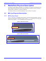
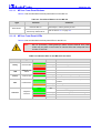
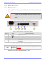
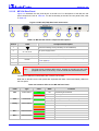


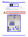


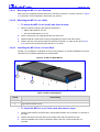
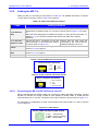


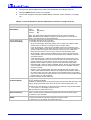


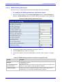
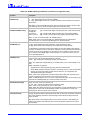
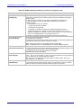

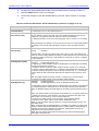


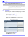

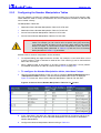


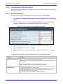
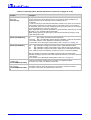

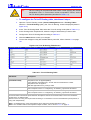


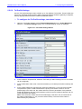
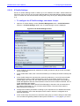
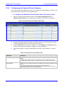
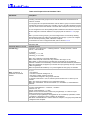
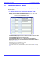

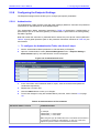


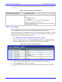


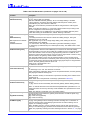
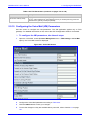
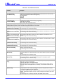


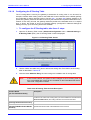

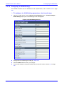
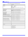


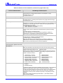


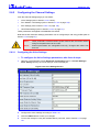

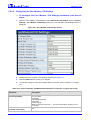
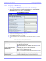
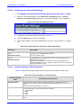


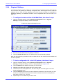
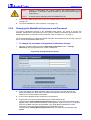
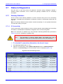
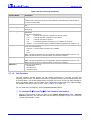
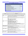

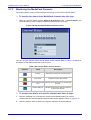

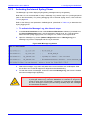

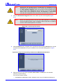


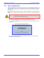
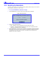


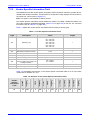


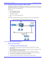
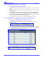


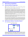


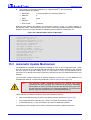
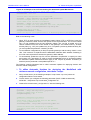

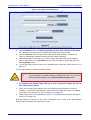
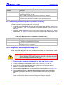
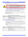
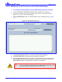


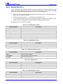


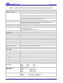


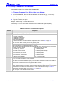


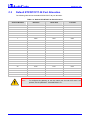

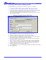

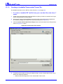
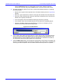
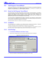

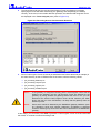
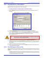
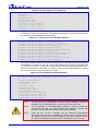
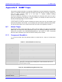

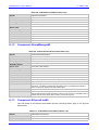


![LTRT-71403 MediaPack MGCP User Manual ver 4[1].](http://vs1.manualzilla.com/store/data/005760883_1-b98cf40cc1cd8cff0fa8bbf345d132db-150x150.png)