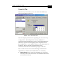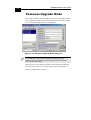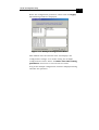
1
BreezeNET DS.11 Series BU-DS.11 RB-DS.11 User’s Guide February 2003 Cat No. 213388 Doc rev2.0 BreezeNET DS.11 Series User’s Guide ii © 2003 by Alvarion Ltd. All rights reserved. No part of this publication may be reproduced in any material form without the written permission of the copyright owner. Trade Names BreezeACCESS®, BreezeNET®, BreezeLINK®, BreezeVIEW™, BreezeMANAGE™, BreezeCONFIG™, BreezeWIZARD™, BreezeSECURE™, AlvariBASE™, AlvariSTAR™, AlvariX™, WALKair® and WALKnet® are trade names of Alvarion Ltd. Other brand and product names are registered trademarks or trademarks of their respective companies. Statement of Conditions The information contained in this manual is subject to change without notice. Alvarion Ltd. shall not be liable for errors contained herein or for incidental or consequential damages in connection with the furnishing, performance, or use of this manual or equipment supplied with it. Warranties; Disclaimers All Alvarion Ltd. (“Alvarion”) products purchased from Alvarion or through any of Alvarion’s authorized resellers are subject to the following warranty and product liability terms and conditions. Important Notice iii Exclusive Warranty Alvarion warrants that the Product hardware it supplies and the tangible media on which any software is installed, under normal use and conditions, will be free from significant defects in materials and workmanship for a period of fourteen (14) months from the date of shipment of a given Product to Purchaser (the “Warranty Period”). Alvarion will, at its sole option and as Purchaser’s sole remedy, repair or replace any defective Product in accordance with Alvarion’ standard RMA procedure. Disclaimer (a) UNITS OF PRODUCT (INCLUDING ALL THE SOFTWARE) DELIVERED TO PURCHASER HEREUNDER ARE NOT FAULT-TOLERANT AND ARE NOT DESIGNED, MANUFACTURED OR INTENDED FOR USE OR RESALE IN APPLICATIONS WHERE THE FAILURE, MALFUNCTION OR INACCURACY OF PRODUCTS CARRIES A RISK OF DEATH OR BODILY INJURY OR SEVERE PHYSICAL OR ENVIRONMENTAL DAMAGE (“HIGH RISK ACTIVITIES”). HIGH RISK ACTIVITIES MAY INCLUDE, BUT ARE NOT LIMITED TO, USE AS PART OF ON-LINE CONTROL SYSTEMS IN HAZARDOUS ENVIRONMENTS REQUIRING FAIL-SAFE PERFORMANCE, SUCH AS IN THE OPERATION OF NUCLEAR FACILITIES, AIRCRAFT NAVIGATION OR COMMUNICATION SYSTEMS, AIR TRAFFIC CONTROL, LIFE SUPPORT MACHINES, WEAPONS SYSTEMS OR OTHER APPLICATIONS REPRESENTING A SIMILAR DEGREE OF POTENTIAL HAZARD. ALVARION SPECIFICALLY DISCLAIMS ANY EXPRESS OR IMPLIED WARRANTY OF FITNESS FOR HIGH RISK ACTIVITIES. iv BreezeNET DS.11 Series User’s Guide (b) PURCHASER’S SOLE REMEDY FOR BREACH OF THE EXPRESS WARRANTIES ABOVE SHALL BE REPLACEMENT OR REFUND OF THE PURCHASE PRICE AS SPECIFIED ABOVE, AT ALVARION’S OPTION. TO THE FULLEST EXTENT ALLOWED BY LAW, THE WARRANTIES AND REMEDIES SET FORTH IN THIS AGREEMENT ARE EXCLUSIVE AND IN LIEU OF ALL OTHER WARRANTIES OR CONDITIONS, EXPRESS OR IMPLIED, EITHER IN FACT OR BY OPERATION OF LAW, STATUTORY OR OTHERWISE, INCLUDING BUT NOT LIMITED TO WARRANTIES, TERMS OR CONDITIONS OF MERCHANTABILITY, FITNESS FOR A PARTICULAR PURPOSE, SATISFACTORY QUALITY, CORRESPONDENCE WITH DESCRIPTION, NON-INFRINGEMENT, AND ACCURACY OF INFORMATION GENERATED. ALL OF WHICH ARE EXPRESSLY DISCLAIMED. ALVARION’ WARRANTIES HEREIN RUN ONLY TO PURCHASER, AND ARE NOT EXTENDED TO ANY THIRD PARTIES. ALVARION NEITHER ASSUMES NOR AUTHORIZES ANY OTHER PERSON TO ASSUME FOR IT ANY OTHER LIABILITY IN CONNECTION WITH THE SALE, INSTALLATION, MAINTENANCE OR USE OF ITS PRODUCTS. (c) ALVARION SHALL NOT BE LIABLE UNDER THIS WARRANTY IF ITS TESTING AND EXAMINATION DISCLOSE THAT THE ALLEGED DEFECT IN THE PRODUCT DOES NOT EXIST OR WAS CAUSED BY PURCHASER’S OR ANY THIRD PERSON'S MISUSE, NEGLIGENCE, IMPROPER INSTALLATION OR IMPROPER TESTING, UNAUTHORIZED ATTEMPTS TO REPAIR, OR ANY OTHER CAUSE BEYOND THE RANGE OF THE INTENDED USE, OR BY ACCIDENT, FIRE, LIGHTNING OR OTHER HAZARD. Important Notice v Limitation of Liability (a) ALVARION SHALL NOT BE LIABLE TO THE PURCHASER OR TO ANY THIRD PARTY, FOR ANY LOSS OF PROFITS, LOSS OF USE, INTERRUPTION OF BUSINESS OR FOR ANY INDIRECT, SPECIAL, INCIDENTAL, PUNITIVE OR CONSEQUENTIAL DAMAGES OF ANY KIND, WHETHER ARISING UNDER BREACH OF CONTRACT, TORT (INCLUDING NEGLIGENCE), STRICT LIABILITY OR OTHERWISE AND WHETHER BASED ON THIS AGREEMENT OR OTHERWISE, EVEN IF ADVISED OF THE POSSIBILITY OF SUCH DAMAGES. (b) TO THE EXTENT PERMITTED BY APPLICABLE LAW, IN NO EVENT SHALL THE LIABILITY FOR DAMAGES HEREUNDER OF ALVARION OR ITS EMPLOYEES OR AGENTS EXCEED THE PURCHASE PRICE PAID FOR THE PRODUCT BY PURCHASER, NOR SHALL THE AGGREGATE LIABILITY FOR DAMAGES TO ALL PARTIES REGARDING ANY PRODUCT EXCEED THE PURCHASE PRICE PAID FOR THAT PRODUCT BY THAT PARTY (EXCEPT IN THE CASE OF A BREACH OF A PARTY’S CONFIDENTIALITY OBLIGATIONS). Electronic Emission Notices This device complies with Part 15 of the FCC rules, ETSI 300-328 and CE. Operation is subject to the following two conditions: 1. This device may not cause harmful interference. 2. This device must accept any interference received, including interference that may cause undesired operation. BreezeNET DS.11 Series User’s Guide vi FCC Radio Frequency Interference Statement This equipment has been tested and found to comply with the limits for a Class B digital device, pursuant to part 15 of the FCC Rules. These limits are designed to provide reasonable protection against harmful interference when the equipment is operated in a residential environment, not withstanding use in commercial, business and industrial environments. This equipment generates, uses and can radiate radio frequency energy and, if not installed and used in accordance with the instructions, may cause harmful interference to radio communications. However, there is no guarantee that interference will not occur in a particular installation. If this equipment does cause harmful interference to radio or television reception, which can be determined by turning the equipment off and on, the user is encouraged to try to correct the interference by one or more of the following measures: • Reorient or relocate the receiving antenna. • Increase the separation between the equipment and receiver. • Connect the equipment into an outlet on a circuit different from that to which the receiver is connected. • Consult the dealer or an experienced radio/TV technician for help Changes or modifications to this equipment not expressly approved by the party responsible for compliance could void the user’s authority to operate the equipment. Important Notice vii FCC Radiation Exposure Statement To comply with FCC RF exposure requirements in section 1.1307, a minimum separation distance of 2 m (79 inches) is required between the antenna and all persons. Antenna Installation WARNING: It is the responsibility of the installer to insure that when using the outdoor antenna kits in the United States (or where FCC rules apply), only those antennas certified with the product are used. The use of any antenna other than those certified with the product is expressly forbidden in accordance to FCC rules CFR47 part 15.204. The installer should configure the output power level of antennas, according to country regulations and per antenna type. viii BreezeNET DS.11 Series User’s Guide Important Notice This installation guide is applicable to BreezeNET DS.11 units and is delivered subject to the following conditions and restrictions: ♦ This manual contains proprietary information belonging to Alvarion Ltd. Such information is supplied solely for the purpose of assisting explicitly and properly authorized users of BreezeNET DS.11equipment. ♦ No part of its contents may be used for any other purpose, disclosed to any person or firm or reproduced by any means, electronic and mechanical, without the express prior written permission of Alvarion Ltd. ♦ The text and graphics are for the purpose of illustration and reference only. The specifications on which they are based are subject to change without notice. ♦ The software described in this document is furnished under a license. The software may be used or copied only in accordance with the terms of that license. ♦ Information in this document is subject to change without notice. ♦ Corporate and individual names and data used in examples herein are fictitious unless otherwise noted. ♦ Alvarion Ltd. reserves the right to alter the equipment specifications and descriptions in this publication without prior notice. No part of this publication shall be deemed to be part of any contract or warranty unless specifically incorporated by reference into such contract or warranty. Important Notice ix ♦ The information contained herein is merely descriptive in nature, and does not constitute a binding offer for the sale of the product described herein. ♦ Any changes or modifications of equipment, including opening of the equipment not expressly approved by Alvarion Ltd. will void equipment warranty and any repair thereafter shall be charged for. It could also void the user’s authority to operate the equipment. ♦ Some of the equipment provided by Alvarion and specified in this manual, is manufactured and warranted by third parties. All such equipment must be installed and handled in full compliance with the instructions provided by such manufacturers as attached to this manual or provided thereafter by Alvarion or the manufacturers. Non-compliance with such instructions may result in serious damage and/or bodily harm and/or void the user’s authority to operate the equipment and/or revoke the warranty provided by such manufacturer. x BreezeNET DS.11 Series User’s Guide Contacting Alvarion Technical Support Should you need assistance beyond the scope of this manual, please contact your local Alvarion reseller or distributor. If they cannot solve your problem, feel free to contact the Alvarion Technical Support Department. The support representative can assist you in solving any problems that cannot be solved by your reseller. When requesting support, please have the following items available: ♦ Configuration of the system, including models of the Alvarion equipment used and other applicable equipment and connecting cables ♦ Hardware and Firmware versions of the Alvarion equipment ♦ Configuration and statistics counters as viewed in the Configuration Utility ♦ Description of the problem encountered To contact Alvarion Technical Support Department, refer to the Alvarion web site: www.alvarion.com/support.htm Table of Contents xi User’s Guide Table of Contents Introduction 1-1 Scope of the Guide ..................................................................... 1-2 System Description .................................................................... 1-3 Functional Description 1-3 BreezeNET DS.11 Compatibility and Standards 1-6 Installation 2-1 Packing List ............................................................................... 2-2 Additional Installation Requirements ......................................... 2-3 Installation Overview.................................................................. 2-4 Outdoor Installation Considerations ........................................... 2-6 Collocating DS.11 Outdoor Units 2-6 Site Selection Factors 2-6 Rooftop Installation 2-8 Antennas for Outdoor Applications 2-8 Antenna Polarization 2-9 Antenna Seal 2-9 Cell Size/Link Distance 2-9 BreezeNET DS.11 Series User’s Guide xii Using Outdoor Range Tables 2-10 Available Antennas 2-10 Precautions 2-11 Compliance with Radio Regulations 2-12 Installing the Outdoor Unit....................................................... 2-13 Connecting the Ground and Antenna Cables 2-15 Connecting the Indoor-to-Outdoor Cable 2-15 Installing the Sun Cover (DS.11D Units Only) 2-17 Installing the Indoor Unit ......................................................... 2-18 Configuring Parameters 2-20 Antenna Alignment 2-21 Verifying Correct Operation ...................................................... 2-22 Verifying Correct Operation of the Indoor Unit 2-22 Verifying Correct Operation of the Outdoor Unit 2-23 What to do if the Self Test Fails 2-24 The DS.11 Configuration Utility 3-1 Installing and Accessing the Configuration Utility....................... 3-3 Configuration Utility Modes ........................................................ 3-4 Unit Configuration Mode 3-5 Firmware Upgrade Mode 3-30 Multiple Unit Configuration Mode 3-34 Table of Contents xiii Debugging Information ............................................................. 3-36 Resetting the SNMP Community Strings ................................... 3-37 Reloading Factory Default Settings........................................... 3-38 System Troubleshooting 4-1 Troubleshooting Guide ............................................................... 4-2 Technical Specifications 5-1 DS.11 FAQ A-1 General ...................................................................................... A-2 Collocation................................................................................. A-5 Performance ............................................................................... A-7 Firmware.................................................................................... A-8 Configuration ........................................................................... A-10 Accessories .............................................................................. A-11 Management............................................................................. A-12 Preparing the Indoor to Outdoor Cable 1 Radio Signal Propagation 1 RF Terms and Definitions 2 xiv BreezeNET DS.11 Series User’s Guide Introduction 1-1 Chapter 1 About This Chapter This chapter is comprised of the following sections: ♦ Scope of the Guide, page 1-2, describes the chapters and topics comprising the BreezeNET DS.11 Series User’s Guide. ♦ System Description, page 1-3, provides an overview of the DS.11 system and introduces the system components. 1-2 BreezeNET DS.11 Series User’s Guide Scope of the Guide This User's Manual provides instructions for planning and setting up a wireless link based on the BreezeNET DS.11 wireless Base Unit and Remote Bridge. ♦ Chapter 1: Introduction - Describes how to use this manual and presents the BreezeNET DS.11 series. ♦ Chapter 2: Installation - Describes how to install the BreezeNET DS.11 units. ♦ Chapter 3: The DS.11 Configuration Utility - Describes how to use the DS.11 Configuration Utility to setup, configure, and manage BreezeNET DS.11 units. ♦ Chapter 4: System Troubleshooting - Solves some of the more common problems which may occur when installing and using the BreezeNET DS.11 units. ♦ Chapter 5: Technical Specifications - Lists the technical specifications of the BreezeNET DS.11 units. ♦ Appendix A: DS.11 FAQ- Answers questions frequently asked by customers. ♦ Appendix B: Preparing the Indoor to Outdoor Cable Explains how to prepare and install the cable connecting the indoor to the outdoor unit. ♦ Appendix C: Radio Signal Propagation - Describes many of the terms and concepts related to antennas and RF (Radio Frequency) systems. Introduction 1-3 System Description The BreezeNET DS.11 wireless Base Unit (BU-DS.11) and Remote Bridge (RB-DS.11) are designed to provide longrange point-to-multipoint links for outdoor applications. The products use direct sequence spread spectrum radio technology operating at the frequency range of 2.4 – 2.4835 GHz, a part of the FCC's unlicensed Industrial, Scientific and Medical (ISM) band. Data is transmitted at rates of up to 11 Mbps, providing network users with full 10BaseT Ethernet speeds. Functional Description The BreezeNET BU-DS.11 and RB-DS.11 can be used as high-speed connections between two or more remote networks. Mail Server File Server Central Network BU-DS.11 Base Unit RB-DS.11 1 Server Remote Network 1 RB-DS.11 2 Server Remote Network 2 RB-DS.11 3 Server Remote Network 3 Figure 1-1: BreezeNET DS.11 Point-to-Multipoint Application BreezeNET DS.11 Series User’s Guide 1-4 BU-DS.11 Wireless Base Unit The BU-DS.11 is an IEEE 802.11b compliant base station that connects one or more remote sites to a central server or Internet connection. In a point-to-multi-point configuration the BU-DS.11 is the central unit while in point-to-point configurations it should be installed at one end of the link. The BU-DS.11 is available in two options: The BU-DS.11 and the BU-DS.11D. The BU-DS.11 is the basic unit, equipped with an antenna integrated into the front cover of the outdoor unit. The BU-DS.11D doesn’t have an integral antenna and is equipped with a connector (on the outdoor unit) for an external antenna (not included with the unit). A protective sun cover is supplied and should be mounted on the front of the outdoor unit. Refer to Antennas for Outdoor Applications on page 2-8 and Available Antennas on page 2-10 for information on how to select an appropriate external antenna. RB-DS.11 Wireless Bridge The RB-DS.11 Wireless Bridge connects a remote Ethernet network to a central network server or Internet site via a BU-DS.11 Multipoint Base Unit. The maximum number of MAC addresses that the unit can handle at any specific time is 1024 and the Aging algorithm is applied at all times. Introduction 1-5 When a station on the Ethernet LAN sends a message that is not destined for a local station, the RB-DS.11 forwards the message to the BU-DS.11. When the BU-DS.11 receives a message destined for a station on the RB-DS.11's LAN, the BU-DS.11 forwards it to the RB-DS.11. In this manner, the RB-DS.11 and the BU-DS.11 work together like a standard network bridge. The first time each station on the RB-DS.11’s LAN sends a message, the station’s address is registered by both the RBDS.11 and the BU-DS.11. It is possible for the RB-DS.11 and BU-DS.11 to store all the addresses necessary to support an entire LAN connected to a RB-DS.11. The RB-DS.11 comes in two options: The RB-DS.11 and the RB-DS.11D. The RB-DS.11 is the basic unit, equipped with an antenna integrated into the front cover of the outdoor unit. The RB-DS.11D has no integral antenna and is equipped with an antenna connector (on the outdoor unit) for the connection of an external antenna (not included with the unit). When this unit is ordered, a protective sun cover is supplied with the unit and should be mounted on the front of the outdoor unit. Refer to Antennas for Outdoor Applications on page 2-8 and Available Antennas on page 210 for information on how to select an external antenna. BreezeNET DS.11 Series User’s Guide 1-6 BreezeNET DS.11 Compatibility and Standards BreezeNET DS.11 products are compatible with the following standards and are interoperable with other IEEE 802.11b compatible, 2.4 GHz direct sequence products. ♦ IEEE 802.11b Wireless LAN. ♦ IEEE 802.3 10BaseT Ethernet. ♦ DHCP for automatic IP address assignment. ♦ SNMP for system management. Installation 2-1 Chapter 2 About This Chapter This chapter is comprised of the following sections: ♦ Packing List, page 2-2, describes the components included with the BreezeNET DS.11 series installation kit. ♦ Additional Installation Requirements, page 2-3, describes the additional standard tools and materials required for installation. ♦ Installation Overview, page 2-4, provides an overview of the installation procedures. ♦ Outdoor Installation Considerations, page 2-6, describes the factors that must be taken into account when installing the outdoor units. ♦ Installing the Outdoor Unit, page 2-13, describes how to install the outdoor unit. ♦ Installing the Indoor Unit, page 2-18, describes how to install the indoor unit and configure the required parameters. ♦ Verifying Correct Operation, page 2-22, describes how to ensure that the installation was successful and the units are functioning correctly. BreezeNET DS.11 Series User’s Guide 2-2 Packing List Ensure that all of the following items are included with the unit’s installation kit: ♦ Indoor unit. ♦ Outdoor unit (includes integrated antenna or antenna connector for optional connection to external antenna). ♦ Sun Cover with screws (with DS.11D units only). ♦ Pole mounting kit for the Outdoor unit (includes two brackets and four sets of bolts, nuts and washers). ♦ 110/220 VAC Power Cord. ♦ 20 meter Indoor-to-Outdoor cable. ♦ 3 shielded RJ-45 connectors. ♦ Configuration Utility diskette. Installation 2-3 Additional Installation Requirements The following materials are not supplied with the installation kit but are required for the installation procedure. ♦ Indoor-to-Outdoor cable* (available in different lengths if the 20m cable included with the unit is insufficient). ♦ Antenna* and RF cable* (if using an external antenna). ♦ Ground cable with an appropriate termination. ♦ Ethernet cable (straight for connecting to a hub). ♦ Installation tools and materials, including appropriate means (e.g. a pole) for installing the outdoor unit. ♦ Crimping tool for RJ-45 connectors. Items marked with an asterisk (*) are available as options from Alvarion. BreezeNET DS.11 Series User’s Guide 2-4 Installation Overview The following outlines the steps of the installation procedure. 1. Select appropriate locations for the outdoor unit, the antenna (if using an external antenna) and the Indoor unit. 2. Mount the outdoor unit. If using an external antenna mount the antenna and connect it to the outdoor unit. 3. Connect a ground cable from the outdoor unit to an appropriate grounding point. 4. Connect the Indoor-to-Outdoor cable to the outdoor unit and route it to the location selected for the indoor unit. Refer to Appendix B for instructions on preparing the Indoor-to-Outdoor cable. 5. Mount the indoor unit. Connect the Indoor-to-Outdoor cable to the indoor unit’s Radio port. 6. Connect the indoor unit’s Ethernet port to the user’s network using an Ethernet cable. 7. Configure the unit’s parameters. 8. Align the antenna and verify connectivity with any other units. NOTE: The indoor unit should only be connected to the power source after it has been connected to the outdoor unit. Installation 2-5 Antenna (BU-DS11D and RD-DS11D units only) OUTDOOR ANT 1 Outdoor Unit Ground Cable to Grounding Point Indoor to Outdoor Unit Cable INDOOR Indoor Unit To LAN To Mains Figure 2-1: General Installation Scheme - Pole Mounting NOTE: Use a straight Ethernet cable to connect the indoor unit to a hub, or use a crossed cable to connect it directly to a PC’s Network Interface Card (NIC). 2-6 BreezeNET DS.11 Series User’s Guide Outdoor Installation Considerations This section describes various considerations to take into account when planning an outdoor installation including site selection, antenna alignment, antenna polarization, antenna seal, and cell size. Collocating DS.11 Outdoor Units Up to three BU-DS.11 units with omni-directional antennas (the exact number depends on the number of nonoverlapping channels available in the relevant regulatory domain) can be collocated on the same building top or tower. Collocating more then three units may decrease performance depending upon the type of antenna and its direction. Each unit should be assigned to one of the non-overlapping channels: 1, 7, or 13 in ETSI or 1, 6 or 11 in FCC. Site Selection Factors When selecting a location for outdoor units and external antennas, remember to take into consideration the following guidelines: ♦ Minimum distance between sites. ♦ Maximum height above the ground. ♦ Maximum line of sight clearance. Installation 2-7 Path of Clearest Propagation A propagation path is the path that signals traverse between the antennas of any two units. The “line” between two antenna sites is an imaginary straight line, which may be drawn between the two antennas. Any obstacles in the path of the “line” degrade the propagation path. The best propagation path is, therefore, a clear line of sight with good clearance between the “line” and any physical obstacle. Physical Obstacles Any buildings or other physical structures such as trees, mountains or other geographic features higher than the antenna and situated in the path between the two sites can constitute obstructions and cause signal attenuation. Install outdoor antennas high enough to avoid any obstacles, which may block the signal. Path Loss Path loss is determined mainly by several factors: ♦ Distance Between Sites: Path loss is lower and system performance better when distances between sites are shorter. ♦ Clearance: Path loss is minimized when there is a clear line of sight. The number, location, size, and makeup of obstacles determine their contribution to path loss. BreezeNET DS.11 Series User’s Guide 2-8 ♦ Antenna Height: Path loss is lower when antennas are positioned higher. Antenna height is the distance from the imaginary line connecting the antennas at the two sites to ground level. Ground level in an open area is the actual ground. In dense urban areas, ground level is the average height of the buildings between the antenna sites. Rooftop Installation Rooftop installations offer several advantages: ♦ Fewer obstacles in the path. ♦ Improved performance due to greater height. Antennas for Outdoor Applications The BreezeNET DS.11 series can be used in point-to-point or point-to-multipoint configurations. Point-to-Point The BU-DS.11/RB-DS.11 can be equipped with a directional antenna. The required antenna gain depends on the required range and performance. Installation 2-9 Point-to-Multipoint Setting up a point-to-multipoint link requires the use of a Base Unit equipped with an omni-directional antenna (or an antenna with sufficient bandwidth to illuminate all units) and at least two remote units equipped with high-gain directional antennas. Antenna Polarization Antenna polarization must be the same at both ends of the link. In most applications, the preferred orientation is vertical polarization, which is best for above ground propagation. To verify antenna polarization, refer to the assembly instructions supplied with the antenna set. Antenna Seal When using outdoor antennas, you must seal all cable connections to prevent water or dirt from entering the connector. Cell Size/Link Distance Cell size is determined by the maximum possible distance between the BU-DS.11 and a RB-DS.11 unit. For open outdoor areas with an unobstructed line of sight between the BU-DS.11 and the RB-DS.11 units, the suggested maximum distance is up to 6 miles (10Km) where ETSI is the regulatory domain and 15 Miles (25 Km) where FCC is the regulatory domain. BreezeNET DS.11 Series User’s Guide 2-10 NOTE: The maximum distance of 24Km/15 miles is achieved using 24 dBi antennas and 24 dBm output power. The maximum distance of 10Km is achieved using 24 dBi antennas and –4dBm output power. Using Outdoor Range Tables Specific range tables, guidelines and information about extended cables can be obtained from your local dealer or the Alvarion central offices. Outdoor installations must have a clear line-of-sight between antennas. Solid obstacles such as buildings or hills can prevent the establishment of a link while partial obstacles such as trees or traffic can reduce range. Extended coaxial cables can cause an increase in signal loss and a reduction in range. Available Antennas The following table lists several antennas suitable for BreezeNET DS.11 units. TIP: Cable length should be minimized in order to gain maximum link budget. Installation 2-11 Model Ant. Gain Ideal for: Dispersion Dimensions HxWxD OMNI-8 8 dBi Establishing 360° coverage for outdoor multipoint links. 360°H/13° V 20" x 5/8" Tubular UNI-16P 16 dBi Medium to long range outdoor links requiring compact form factors. 28°H/28° V 11" x 11" x 3.5" UNI-24 24 dBi Long range outdoor point-to-point links. 6°H/10° V 24" x 36" x 15" Table 2-1: Available Antennas Precautions Outdoor units and antennas should be installed ONLY by experienced antenna installation professionals who are familiar with local building and safety codes and, wherever applicable, are licensed by the appropriate government regulatory authorities. The system complies with the ETS 300 385 standard and is protected against secondary lightning strikes when its outdoor unit is properly grounded according to the applicable country-specific industry standards for protection against lightning. The system complies with EN 61000-4-5, test level 3 (2kV). 2-12 BreezeNET DS.11 Series User’s Guide Failure to do so may void the BreezeNET Product Warranty and may expose the end user to legal and financial liabilities. Alvarion and its resellers or distributors are not liable for injury, damage or violation of government regulations associated with the installation of detached antennas. Compliance with Radio Regulations Regulations regarding maximum antenna gains vary from country to country. It is the responsibility of the end user to operate within the limits of these regulations as well as to ensure that the professional installer is aware of these regulations. Violation of government regulations exposes the end user to legal and financial liabilities. Alvarion, its resellers and distributors shall not be liable for expense or damage incurred as a result of installations that exceed local transmission power limitations. Installation 2-13 Installing the Outdoor Unit The outdoor unit can be secured to the pole using one of the following options: ♦ Special brackets sets (supplied with each unit). There are two pairs of threaded holes on the units, allowing the use of the brackets with various pole widths. ♦ Metal bands (9/16” wide, minimum 12” long). Figure 2-2 shows the locations of the holes and grooves on the back of the unit. Figure 2-3 illustrates the method of installing a unit on a pole using the supplied brackets. NOTE: Make sure to install the unit with the bottom panel (the panel with the signal strength bar and LEDs) facing downward. Figure 2-2: Installation Holes/Grooves BreezeNET DS.11 Series User’s Guide 2-14 Figure 2-3: 3” Pole Mounting Installation Using the Supplied Brackets NOTE: When inserting the open-ended bolts, make sure to insert them with the grooves pointing outwards; these grooves are intended to allow fastening of the bolts with a screwdriver. Installation 2-15 Connecting the Ground and Antenna Cables The Ground terminal (marked ) is located on the bottom panel of the outdoor unit. The Antenna RF connector (marked ) is located on the top panel of the BU-DS.11D outdoor unit. NOTE: In DS.11 units with two antenna connectors, always use the connector marked - 1. 1. Connect one end of the grounding cable to the Ground terminal and connect the other end to a good ground connection. 2. For DS.11D units, connect an RF cable between the antenna connector and the antenna. Connecting the Indoor-toOutdoor Cable The following steps and figure illustrate how to connect the indoor-to-outdoor cable. 1. Remove the two screws holding the waterproof seal to the outdoor unit and remove the waterproof seal. 2. Unscrew the top nut from the waterproof seal. BreezeNET DS.11 Series User’s Guide 2-16 Figure 2-4: The Waterproof Seal 3. Route a straight, uncrimped Ethernet cable (8-wire, 24 AWG) through both the top nut and the waterproof seal. NOTE: The 8-wire cable should be shielded. 4. Insert and crimp the RJ-45 connector. Refer to Appendix B for instructions on preparing the RJ-45 cable connector. 5. Connect the Ethernet cable to the Outdoor unit RJ-45 connector. 6. Replace the waterproof seal and then the top nut. Make sure that the external jack of the cable is well inside the waterproof seal to guarantee a good seal. 7. Route the cable to the location selected for the Indoor unit. Installation 2-17 Installing the Sun Cover (DS.11D Units Only) With DS.11D units, a plastic Sun Cover is provided to protect the unit from direct sunlight. It is mounted to the front of the unit using four standard screws (included). 2-18 BreezeNET DS.11 Series User’s Guide Installing the Indoor Unit Route the Indoor-to-Outdoor cable into the building so that it conveniently reaches the indoor unit while avoiding interference sources. It is recommended that the cable be a little longer then necessary. The cable is supplied open ended so it can be conveniently threaded as shown into the building. 1. The unit can be placed on a desktop or a shelf. Alternatively, it may be wall-mounted. The drilling template included with the unit can be used to simplify the wall installation process. 2. Assemble an RJ-45 connector with a protective cover on the indoor side of the Indoor-to-Outdoor cable. Refer to Appendix B for instructions on preparing the RJ-45 cable connector. 3. Connect the Indoor-to-Outdoor cable to the Radio connector, located on the top panel of the indoor unit shown in Figure 2-6 on page 2-20. The Indoor-toOutdoor cable should be connected to the unit before the unit is connected to the mains power. Installation 2-19 4. After connecting the outdoor unit to the indoor unit using the Indoor-to-Outdoor cable, connect the power cord to the unit’s AC socket, located on the bottom panel shown in Figure 2-5. Connect the other end of the power cord to the AC mains after verifying that the unit is rated for the voltage in the country of use; the AC rating is indicated on the bottom panel of the Indoor unit. NOTE: The color codes of the power cable are: Brown: phase ~ Blue: neutral 0 Yellow/Green: grounding Figure 2-5: Indoor Unit Bottom Panel 5. Verify that the yellow POWER LED located on the top panel is lit, indicating that the unit is supplying power to the radio port. BreezeNET DS.11 Series User’s Guide 2-20 Figure 2-6: Indoor Unit Top Panel 6. Connect the 10BaseT connector to the network. The cable connection should be straight Ethernet if connecting the Indoor unit to a Hub and a crossed cable if connecting it directly to a PC Network Interface Card (NIC). NOTE: The length of the Ethernet cable connecting the indoor unit to the user's equipment, together with the length of the Indoor-to-Outdoor cable, should not exceed 90 meters. Configuring Parameters Before aligning the antenna, certain key parameters must be configured to enable connectivity with linked units. See Unit Configuration Mode on page 3-5 for more information. Installation 2-21 Antenna Alignment Usually, low gain antennas do not require alignment due to their very wide radiation pattern. High gain antennas, including the integral antenna of DS.11 units, have a narrow beamwidth necessitating an alignment procedure in order to optimize the link. Check the antenna alignment by using the RSSI bar on the bottom panel of the RB-DS.11 unit. To align the antenna: 1. Confirm that the units at both ends of the link are receiving power. 2. Synchronize the units by aligning the antennas at the central and remote sites until maximum signal quality is obtained. Check the signal quality RSSI bar on the bottom panel of the RB-DS.11. The first LED lights red to indicate that the unit is working. The remaining nine LEDs light green to indicate the signal strength. The stronger the signal, the more LEDs are lit. Rotate the antenna to the left or right until you reach the point of maximum RSSI reading. Make sure that at all times the front of the antenna faces the general direction of the BU-DS.11. BreezeNET DS.11 Series User’s Guide 2-22 Verifying Correct Operation The following sections describe how to ensure that the units are correctly installed and functioning properly. Verifying Correct Operation of the Indoor Unit To verify proper operation, check the LED indicators located on the top panel of the indoor unit as shown in Figure 2-6 on page 2-20, and as described in Table 2-2. Name Description Functionality POWER Power indication Green - 48VDC is present on the Radio RJ45 port. Off - No power is supplied to the Radio RJ45 port. LINK Self Test and Ethernet Link indication The LINK LED indicates end-to-end connection between the outdoor unit and the Ethernet connection to the indoor unit. Off – No Ethernet connectivity has been detected between the outdoor unit and the device connected to the indoor unit. Orange– Self-test passed and Ethernet connection is confirmed by the Outdoor unit (Ethernet integrity check passed). Table 2-2: Indoor Unit LEDs Installation 2-23 Verifying Correct Operation of the Outdoor Unit To verify proper operation, check the LED indicators located on the bottom panel of the outdoor unit. Name Description Functionality WLAN Wireless Link Indicator Blinking Green – Data received or transmitted on the wireless link. Blinking rate is slower when there is less wireless traffic. DC Power Self Test and Power indication Green – Power is available and self test passed. Red – Self test failed. Firmware did not load successfully. ETH Ethernet activity/ connectivity indication OFF –Ethernet connectivity is OK. No traffic activity detected on the port. Blinking Green –Ethernet connectivity is OK, with traffic on the port. Red – No Ethernet connectivity. When this state occurs, check the Ethernet cable and Indoor-toOutdoor cable connections. RSSI BAR RB-DS.11: Received Signal Strength Indication BU-DS.11: Number of associated RB-DS.11 units Table 2-3: Outdoor Unit LEDs BreezeNET DS.11 Series User’s Guide 2-24 What to do if the Self Test Fails If the Self-Test fails (DC Power LED light remains red), try the following: ♦ Reset unit (Disconnect/reconnect the power). ♦ Check the Indoor-to-Outdoor cable. ♦ Reset to factory defaults (see page 3-38). Contact technical support. The DS.11 Configuration Utility 3-1 Chapter 3 About This Chapter The DS.11 Configuration Utility is an SNMP-based utility that provides a consistent view of the wireless network. The system administrator can use the DS.11 Configuration Utility to control a large number of DS.11 units from a single location. The Configuration Utility can be used to manage BU-DS.11 and RB-DS.11 units as well as other members of the BreezeNET DS.11 family including the WBS, WBC, APDS.11 and SA-DS.11. The description in this manual, however, is limited to management and configuration of BUDS.11 and RB-DS.11 units. Refer to the DS.11 section of www.alvarion.com for more information on how to use the utility with other products. Using the Configuration Utility you can: ♦ Assign radio channels for optimal cell operation. ♦ Configure units with a specified IP address. ♦ Set the SNMP Read/Write Community strings. BreezeNET DS.11 Series User’s Guide 3-2 ♦ Verify the status of all units in the network. ♦ Configuration of a wide range of operational parameters, including WLAN, IP and Security parameters. ♦ View Tx and Rx counters. ♦ Obtain general information such as the Firmware version and system name. This chapter is comprised of the following sections: ♦ Installing and Accessing the Configuration Utility, page 3-3, describes how to install and initialize the configuration application. ♦ Configuration Utility Modes, page 3-4, describes the various modes, functions and parameters of the Configuration Utility. ♦ Debugging Information, page 3-36, describes how to create a log file for the purposes of receiving technical support. ♦ Resetting the SNMP Community Strings, page 3-37, describes how to restrict management access by defining the SNMP Read/Write Community string. ♦ Reloading Factory Default Settings, page 3-38, describes how to revert unit parameters to their original factory defaults. The DS.11 Configuration Utility 3-3 Installing and Accessing the Configuration Utility The Configuration Utility is provided for installation on a 3.5” diskette. 1. Insert the provided diskette into the computer where you wish to install the Configuration Utility. 2. Run DS11mgr.exe. 3. Follow all instructions until you are informed that the Utility was installed successfully. 4. Run the Configuration Utility from the Start menu by selecting it in the DS.11 Configuration Utility folder under Programs. 3-4 BreezeNET DS.11 Series User’s Guide Configuration Utility Modes There are several DS.11 Configuration Utility modes of operation; these options are selected via the Mode menu in the configuration utility main window (shown below). The selected mode(s) is indicated by a check mark in the menu. ♦ Unit configuration: This is the default mode and is used for setting parameters as detailed in this manual. ♦ Firmware upgrade: Used for upgrading the embedded software in managed units; refer to Firmware Upgrade Mode, on page 3-30 for instructions on using this feature. ♦ Multiple configuration: Used for setting configuration parameters for more than one unit simultaneously; refer to Multiple Unit Configuration Mode, on page 3-34, for instructions on using this feature. ♦ Trap quick view: When set to this mode, the PC switches automatically to the Trap Monitor tab when Unit Configuration mode is selected. The DS.11 Configuration Utility 3-5 Unit Configuration Mode The following sections describe the various screens, controls and parameters available in Unit Configuration mode. Control Window In this section, you can: ♦ Discover the units that are connected to the network. ♦ View the DS.11 units that have been discovered by their IP address. ♦ Select the units you wish to manage. ♦ Locate units behind a router that cannot be detected by the autodiscovery feature ♦ Assign unit IP addresses based on unit MAC addresses. ♦ Set the SNMP Community string. NOTE: If there are many units in the managed network, you can enlarge the list box by clicking the horizontal line above the list Click again to toggle back the default display state. The list box also displays the location of each unit, as set in the Station Status window. BreezeNET DS.11 Series User’s Guide 3-6 Tabs Section This section consists of several tabs, each containing parameters required for the management of the selected unit; the number of tabs displayed varies between the type of managed unit. The different tabs are described in the following sections. When you switch between the tabs, the unit selection section with the selected unit address remains displayed. Figure 3-1: DS.11 Configuration Utility Main Window (Station Control Tab) The DS.11 Configuration Utility 3-7 Control Window The following sections describe how to work with the Control Window. Selecting Units You can select a unit to manage in one of the following ways: ♦ Click the Network Autodiscovery button. All the IP addresses of units in the same domain but not hidden behind a router (under the selected community) are displayed in the list box underneath the button. Click on an address to select the corresponding unit for viewing and configuration. ♦ Type the unit's IP address in the Locate Unit field (for stations which are located behind a router) and click This will add the unit information to the selection list. Setting the SNMP Community String Type the known Read/Write Community string in the Community field (the default string is public for read and private for read/write) and click the button to confirm. . BreezeNET DS.11 Series User’s Guide 3-8 Assigning and Editing IP Addresses Manually (based on MAC addresses) This section describes how to manually input or modify the IP address of the selected unit. 1. Click the Set IP button. The Set IP dialog box appears. Figure 3-2: The Set IP Dialog Box 2. Type the parameters in the appropriate fields and click OK; the MAC address is shown on the bottom label of the Indoor and Outdoor units. A message box is displayed notifying you when the changes are to take affect. This feature can be used only if the DS.11 Configuration Utility is on the same Ethernet segment as the unit and not behind the router. NOTE: In order to see the unit after assigning the IP address, the PC with the Configuration utility should be on the same IP subnet as the assigned IP address. Units receive auto IP address if there is no DHCP server and the unit is configured to work in the Smart mode. The IP address will be chosen randomly in the 169.254.x.x range with a subnet mask of 255.255.0.0. The DS.11 Configuration Utility 3-9 Application Control Buttons The following buttons always appear at the bottom of the Configuration Utility window. Additional buttons, specific to certain tabs, are explained when relevant. ♦ Hide to Tray: Minimizes the application into the icon, placed in the Windows task bar (at the bottom of the Windows desktop). To restore the application, click the icon. ♦ Apply: Implements any changes you made. ♦ Refresh: Refreshes the window with the most recent data from the unit. ♦ Cancel: Closes the window without implementing any changes you made. BreezeNET DS.11 Series User’s Guide 3-10 Configuration Utility Tabs The following sections describe the tabs and parameters provided by the Configuration Utility in Unit Configuration mode. Station Status Tab The Station Status tab displays general information regarding the unit's firmware and hardware versions as well as general unit address information. Figure 3-3: Station Status Tab (RB-DS.11) The DS.11 Configuration Utility 3-11 The Station Status tab is comprised of the following components: ♦ System Name: The name of the selected unit. ♦ Location: A user-defined description of the location of the selected unit, up to 28 ASCII characters long (optional). ♦ MAC Address: MAC address of the selected unit. ♦ Firmware: The current firmware version. ♦ BSS Address (RB-DS.11 units only): Defines the MAC address of the BSS, which is the BU-DS.11 the unit is associated with. ♦ Associated Stations (BU-DS.11 units only): Details concerning the RB-DS.11 units associated with the BU-DS.11. The information provided for each associated RB-DS.11 unit includes it’s MAC address and the level at which it is received by the BU-DS.11 (RSSI). BreezeNET DS.11 Series User’s Guide 3-12 IP Parameters Tab The IP Parameters tab enables you to define or edit the IP parameters of units. Figure 3-4: IP Parameters Tab ♦ IP Address: The IP address of the selected unit. ♦ Subnet mask: The Subnet mask of the selected unit. ♦ Default gateway: The default gateway of the selected unit. The DS.11 Configuration Utility ♦ DHCP: Sets the way your system utilizes the Dynamic Host Configuration Protocol (DHCP, used for automatic IP assignment). Always: The system searches for a DHCP server each time the unit is turned on. Smart: The system searches for a DHCP server only if no IP address was assigned. If an IP address was assigned manually, the system will not search for a DHCP server. Never: The system never searches for a DHCP server. The default value is Smart. NOTE: When the unit is configured to use a DHCP server and none exists, the unit will assign itself an automatic class B address in the range 169.254.X.X; this can be used with Auto Discovery when the MAC address is not available. 3-13 BreezeNET DS.11 Series User’s Guide 3-14 SNMP Parameters Tab The SNMP parameters tab allows you to define or edit the SNMP community strings and the SNMP-related parameters. Figure 3-5: SNMP Parameters Tab The SNMP Parameters tab is comprised of the following components: ♦ Read: The read-only community string of the unit. Default is public. ♦ Read/Write: The read/write community string of the unit. Default is private. This value is displayed as asterisks for security purposes. ♦ Trap Host IP Address: The IP address of the host to which SNMP traps are sent. ♦ Click to apply the defined Trap Host IP address. ♦ Click to disable the sending of traps (inserts a value of 255.255.255.255). The DS.11 Configuration Utility Counters Tab The Counters tab displays a series of statistics relating the usage and performance. Figure 3-6: Counters Tab (BU Units) Figure 3-7: Counters Tab (RB Units) 3-15 BreezeNET DS.11 Series User’s Guide 3-16 Using the Counters tabs, you can view a wide range of performance data at both sides of the link. For RB units, you can monitor the received signal strength through the RSSI (Received Signal Strength Indication) bar indicator at the bottom of the window. This RSSI bar can be used to optimize antenna alignment and improve link quality. Additional performance counters displayed in this window include the following. To obtain a graph that displays the counter values, select a counter and drag it to the icon. ♦ Tx Counters Tx Fragments: The number of transmitted frames. The count includes data, control, management frames and the number of retransmissions of data frames (for example, if the same data frame is retransmitted ten times then the count will increase ten times). Tx Frames: The number of frames successfully transmitted to the wireless media. The count includes the first transmission of data frames (without retransmissions), and the number of control and management frames. Multicast Tx Frames: The number of successfully transmitted multicast frames. Retry Count: The number of frames that were successfully transmitted after one of more retransmissions. Multiple Retry: This counter is incremented when a packet is successfully transmitted after more than one retransmission. The DS.11 Configuration Utility 3-17 Failed Count: This counter is incremented when a packet is not transmitted successfully due to the number of transmit attempts exceeding either the Short Retry Limit or Long Retry Limit. ♦ Rx Counters Rx Fragments: The number of frames received, including data, control, and duplicate data frames. Multicast Rx Frames: The number of received multicast frames. FCS Error: The number of frames received with a CRC error. FCS Error (%): The percentage of frames received with a CRC error, calculated as follows: 100*FCS Error / (Rx Fragments + Multicast Rx Frames + FCS Error). Frame Duplicate: The number of duplicate frames that were received. ♦ Link Counters The Tx Success and Tx Fail counters displayed at the end of the counters list are link-specific; to activate these counters for a specific link, select the MAC address of the unit at the other end of the link and click Apply. BreezeNET DS.11 Series User’s Guide 3-18 When you click the Reset Counters button, these counters are actually reset (unlike the other counters which are only reset on screen). Tx Success: The number of data and management frames (except to beacons and multicasts) that were transmitted and acknowledged by the intended recipient. Tx Fail: The number of data and management frames (except to beacons and multicasts) that were transmitted without being acknowledged by the intended recipient. Tx Fail (%) – The percentage of data and management frames (except to beacons and multicasts) that were transmitted without being acknowledged by the intended recipient, calculated as follows: 100*T x Fail / (Tx Success x Tx Fail) ♦ Resetting Counters You can reset the counters displayed in the Counters tab by clicking the Reset Counters button. All displayed values are reset to display zero. Note that this action does not reset the counters stored in the actual unit, but just resets the values displayed in the screen (an exception to this are the Link Counters). Therefore, if you exit the Counters tab, after performing a reset and reopen it at a later time the counter values are displayed to reflect the values stored in the unit. To reset the counters in the unit, turn off the unit and then turn it back on. The DS.11 Configuration Utility WLAN Parameters Tab The WLAN parameters tab allows you to define or edit parameters related to the Wireless LAN environment in which the selected unit is operating. The window displayed varies depending on the type of unit selected. Figure 3-8: WLAN Parameters Tab (BU Units) 3-19 3-20 BreezeNET DS.11 Series User’s Guide Figure 3-9: WLAN Parameters Tab (RB Units) The WLAN Parameters tab is comprised of the following components: ♦ Regulatory Domain: Displays the regulatory authorities in the relevant country of use (e.g., Canada, ETSI, FCC, Japan). ♦ Power: Displays the current output power level at the antenna port. ♦ ESSID: An ASCII string of up to 32 characters used to identify a WLAN that prevents the unintentional merging of two co-located WLANs. It is essential that the ESSID is set to the same value in all Remote Bridges and Base Units that should communicate with each other. The ESSID field is case-sensitive. The DS.11 Configuration Utility 3-21 ♦ Maximum data rate: By default, the unit adaptively selects the highest possible rate for transmission. Under certain conditions (for range/speed trade-off) you may decide not to use the higher rates. Possible values are 2, 5.5 or 11 Mbps. The default value is 11 Mbps. ♦ Transmit diversity: The antenna diversity option, which must be set to Antenna No. 1. NOTE: In the present product release, antenna diversity is not supported; therefore, always select Antenna No. 1. ♦ Range: The operative range of your WLAN or Wireless Link in the drop down list. This parameter affects the acknowledge delay time which needs to be increased in long links. The default value is up to 5 km. ♦ Channel: Channel selection varies, depending on the type of unit. For BU-DS.11 units, select the channel that the unit will use by selecting a value (range: 1-13, depending on your regulatory domain) from the Channel drop down menu. Refer to Table 3-2 on page 3-23 for the list of corresponding frequencies. For RB-DS.11 units, there are two channel setting options: if you select the Fixed Channel option by clicking the appropriate radio button, then the RB-DS.11 will search for the BU-DS.11 unit on the selected channel (from the Channel pull down field) and synchronize with it. The channel you select must match the channel selected in the BU-DS.11 unit at the other end of the link. BreezeNET DS.11 Series User’s Guide 3-22 If you select the Scanning Mode option (by selecting the appropriate radio button), you can specify preferred channels by clicking one or more of the buttons displayed at the bottom of the window. In this mode, the RB-DS.11 will first search for the BU-DS.11 unit on the channel you select in the Channel pull down field and synchronize with it if the link is established. If the RB-DS.11 does not find the BU-DS.11, it will scan and search for one of the preferred channel frequencies you selected. If it does not find the BUDS.11 on any of the preferred channels, it will continue to scan until it finds the BU-DS.11 on one of the channels permitted according to the regulatory domain. Table 3-1 describes the channels used in each regulatory domain, the default channel, the maximum output power and the default output power. Regulatory Domain Lowest Channel Highest Channel Default Channel Max. Output Power Default Output Power ETSI 1 13 7 14 4 FCC 1 11 6 24 24 TELEC 1 13 7 14 6 France 10 13 11 14 4 Canada 1 11 6 24 24 Table 3-1: Regulatory Domains Specifications The DS.11 Configuration Utility 3-23 Channel Frequency 1 2412 MHz 2 2417 MHz 3 2422 MHz 4 2427 MHz 5 2432 MHz 6 2437 MHz 7 2442 MHz 8 2447 MHz 9 2452 MHz 10 2457 MHz 11 2462 MHz 12 2467 MHz 13 2472 MHz Table 3-2: Frequency List NOTE: The frequencies listed in the table are at the center of the channel. Each channel occupies 22MHz, therefore each channel occupies -11MHz to +11 MHz from the frequency specified. BreezeNET DS.11 Series User’s Guide 3-24 Station Control Tab The Station Control tab enables you to revert the unit parameters to their factory defaults, reset the unit and export the unit’s configuration to a configuration file. Figure 3-10: The Station Control Tab The Station Control tab is comprised of the following components: ♦ Station Control: Click the Default button for all parameters to revert to the factory defaults. ♦ Reset Unit: Click the Reset button to reset the unit and apply any changes made to the system parameters. ♦ Export Configuration - Click the Export button to export the current basic configuration of this unit to a file. A popup window is displayed prompting you to specify the name of the file. The created file can be used to save the configuration information or to send it to tech support as a reference for troubleshooting. The DS.11 Configuration Utility 3-25 Security Tab The Security tab enables you to the define the WEP keys used of encryption purposes. Figure 3-11: Security Tab This tab displays information regarding the unit’s security configuration. Wired Equivalent Privacy (WEP) is an authentication algorithm that protects authorized Wireless LAN users against eavesdropping and is implemented in BreezeNET DS.11 units. WEP is defined in the IEEE 802.11b standard. This encryption is applicable for both authentication and data and the key length is 40 bits. DS.11 units can use one of the following authentication algorithms (as defined in the IEEE 802.11b standard). ♦ Open System: Any station in the WLAN can associate with any other unit and receive and transmit data freely (null authentication). BreezeNET DS.11 Series User’s Guide 3-26 ♦ Shared Key: Only stations using a shared key encryption are allowed to associate. The default authentication algorithm is Open System. If you select the Shared Key algorithm, set the following parameters: ♦ Default Key ID – Sets the key for encryption. ♦ WEP Key – Defines the encryption keys used. Define each key by clicking the appropriate WEP Key row and entering ten hexadecimal characters (five sets of two characters each) for each of the four keys. After clicking Apply, the WEP Key values are displayed as zeros for security reasons. The default WEP key is the first key. NOTE: All units in the same cell should use the same key. The DS.11 Configuration Utility 3-27 Advanced Tab The Advanced tab provides additional performance parameters. Figure 3-12: Advanced Tab The Advanced tab is comprised of the following components: ♦ CW Min/Max: The size of the contention window. The contention window back-off algorithm is a method used to resolve contention between different stations trying to access the medium. The valid range is from 7 to 1023. Defaults are 31 for CW Min and 1023 for CW Max. ♦ RTS Threshold: The minimum packet size required for an RTS (Request to Send) to be sent. For packets with a size below the RTS Threshold value, an RTS is not sent and the data packet is transmitted directly to the WLAN. ♦ Short Retry Limit: The maximum number of transmission attempts for a frame that is shorter than or equal to the RTS Threshold. The default value is 8. BreezeNET DS.11 Series User’s Guide 3-28 ♦ Long Retry Limit: The maximum number of transmission attempts for a frame that is longer than the RTS Threshold. The default value is 4. ♦ Basic Rate: The maximum rate of multicast, broadcast and control frames transmissions. Multicast and broadcast transmissions are not acknowledged; therefore there is a chance that such transmissions will not be properly received without the possibility of using the acknowledgement mechanism for retransmission. Therefore, it is recommended to use a lower rate for transmission of broadcast, multicast and control frames, to increase the probability that they will be received without errors. Enter the data rate at which broadcast, multicast and control frames are transmitted. The default value is 2 Mbps. NOTE: The Basic Rate parameter should be changed only if you are sure that all units in the cell can handle the defined rate. Use this parameter with caution, as it may bring the link down. ♦ Power: The transmit power level. The possible range is from –4dBm to +24dBm. NOTE: The Power setting should not exceed the maximum output allowed in the applicable regulatory domain according to Table 3-1 on page 3-22. The DS.11 Configuration Utility Trap Monitor Tab The Trap Monitor tab enables you to view messages received from the selected unit. Figure 3-13: Trap Monitor Tab When an event occurs, a trap is sent to the defined host address (the setting is made in the SNMP Parameters tab described on page 3-14). This window displays the recorded traps. Click Clear List to clear the display area. 3-29 BreezeNET DS.11 Series User’s Guide 3-30 Firmware Upgrade Mode This mode enables the embedded software in managed units to be upgraded. When you select this mode from the Options menu, the following window is displayed. Figure 3-14: Firmware Upgrade Mode dialog box NOTE: The Configuration utility does not resolve the topology of the cell. Therefore, firmware upgrades should be made from the central point where the BUs are located. The list box on the left-hand side of the dialog box displays the managed units; it is sorted sequentially by BU-DS.11 followed by RB-DS.11 units. The DS.11 Configuration Utility 3-31 To upgrade the firmware: 1. Select the units that you wish to upgrade from the list box. Use Shift-click and/or Ctrl-click to select multiple units, or select multiple units by dragging with the mouse. 2. Specify the firmware file you wish to use in the Local file name fields; there are separate fields for files of different device type. The field text is displayed in blue when corresponding unit types are selected in the list box. 3. In the Remote File Name field, enter the Read/Write community string of the unit(s). 4. Click Advanced to change the settings of the TFTP session used in the upgrade download. 5. Click Start to initiate the firmware upgrade; progress bars are displayed indicating the progress of the operation. If both BU-DS.11 and RB-DS.11 devices are selected, the program will upgrade RB-DS.11 units first. BreezeNET DS.11 Series User’s Guide 3-32 At the end of the upgrade session, the following window is displayed indicating that the operation was successful. Figure 3-15: Firmware Upgrade Process NOTES: Do not disconnect any cables or try to stop the process before downloading is completed. All configured parameters are saved during the upgrade/download procedure. The DS.11 Configuration Utility 3-33 Advanced TFTP Settings This section describes how to configure advanced parameters when using the firmware upgrade utility. Figure 3-16: Advanced TFTP Setup The Advanced TFTP Setup window enables you to tune the TFTP session parameters for a more efficient firmware upgrade, depending on your actual deployment. ♦ Packet timeout: Defines the time (in seconds) it takes for a packet to timeout. The range is from 1 to 30 seconds with a default of 3 seconds. ♦ Packet Retries: Defines the number of times that a packet will be sent after it timeouts in a TFTP session. The range is from 1 to 5 retries with a default of 3 retries. ♦ Session Retries: Defines the number of times a TFTP session will be repeated before the firmware upgrade operation is designated a failure. The range is 1-5 retries with a default of 3 retries. BreezeNET DS.11 Series User’s Guide 3-34 Multiple Unit Configuration Mode This feature enables configuration parameters to be downloaded to multiple units simultaneously. When you select this option from the Options menu, all configuration windows are displayed as write-only. Irrelevant parameters are disabled. NOTE: The Configuration Utility does not resolve the topology of the cell. Therefore, multiple unit configuration operations should be done at the location where the BU is are located. Select the units to be upgraded from the list box on the lefthand side of the tabs. Use Shift-click and/or Ctrl-click to select multiple units. The DS.11 Configuration Utility Enter the configuration parameter values and click Apply. The following window is displayed. Figure 3-17: Multiple Configuration Mode This window lists the selected units and displays the configuration changes to be made during the multiple configuration session. Select the Reset units after setting parameters check box to reset all selected units. A log of the multiple configuration session is displayed during and after the operation. 3-35 BreezeNET DS.11 Series User’s Guide 3-36 Debugging Information This option enables you to create a log file named BreezeLog.log. You can send this log file to Alvarion technical support and receive help based on the information recorded in this file. To start recording, open the Debug Info menu item in the Main menu and select Start Log. When you finish recording (usually after 24 hours) select Stop Log from the Debug Info menu and send the file to Alvarion technical support representatives. The DS.11 Configuration Utility 3-37 Resetting the SNMP Community Strings The SNMP Read/Write Community strings are an SNMP security feature to restrict management access to authorized persons only. To reset the SNMP community strings, insert a paper clip or another suitable tool into the Reset button on the top panel of the unit while the unit is operating. The community strings are reset to the default values, private (Write) and public (Read). 3-38 BreezeNET DS.11 Series User’s Guide Reloading Factory Default Settings To reset the unit to the factory defaults: 1. Disconnect the power cable from the indoor unit. 2. Insert a paper clip or another suitable tool into the Reset button on the top panel of the unit (see Figure 2-6 on page 2-20). Keep the Reset button pressed while inserting the power cable back into its socket. System Troubleshooting 4-1 Chapter 4 About This Chapter The following troubleshooting guide provides answers to some of the more common problems that may occur when installing and using the BreezeNET DS.11. If problems not mentioned in this guide should arise, checking the Ethernet and WLAN counters may help. If the problem persists, please feel free to contact your local distributor or the Alvarion Technical Support Department. BreezeNET DS.11 Series User’s Guide 4-2 Troubleshooting Guide Problem and Indication Possible Cause Corrective Action No power to unit. Power LED is off. Power cord is not properly connected. Verify power cord is properly connected to the BreezeNET unit and to the power outlet. Failure to establish wireless link. WIRELESS LINK LED is off and unit resets every few minutes. 1. Power supply to units may be faulty 1. Verify power to units. 2. The RB-DS.11 units may not have the same ESSID as the BUDS.11. 2. Verify that all units in the network have the same ESSID (ESSID must be identical in all units in the WLAN; the ESSID is case sensitive). Check that the units are on the same channel. 3. Verify wireless link: Set BU-DS.11 and RB-DS.11 units side by side. Power on each unit and see if a wireless link is established (even “D” models without their external antennas should establish a link if placed side by side). If the units fail to associate, reset units to factory default values. The units should now establish a wireless link. System Troubleshooting 4-3 Problem and Indication Possible Cause Corrective Action Failure to establish wireless link (“D” models/external antennas) 1. Power supply to units may be faulty. 1. Verify power to units. 2. Cables may be improperly connected 3. There may be some problem with antenna installation. 2. Verify that all cables are connected securely. 3. Refer to previous Section and verify wireless link between the units. 4. Verify that the antenna(s) are properly installed (see relevant section in this manual): Check antenna alignment. Verify that antenna polarization is the same at both ends. Verify that the range matches specifications. Verify line-of-sight/antenna alignment/antenna height. BreezeNET DS.11 Series User’s Guide 4-4 Problem and Indication Possible Cause Corrective Action Wireless link established, but there is no Ethernet activity (BU-DS.11 and RB-DS.11 units). 1. Ethernet hub port or UTP cable is faulty. 1. Check that the LINK LED is lighted Green. If this is not the case, the port is inactive. Try another port on the hub or another UTP cable. 2. Ethernet port in unit is faulty. 3. The RB-DS.11 is associated to a BU-DS.11 unit that is not connected correctly to the LAN. 2. Verify that Ethernet port in unit is working. Ping unit to verify Ethernet connection. 3. Verify that you are using a cross-over UTP cable (pins 1 & 3, 2 & 6) if connected directly to a workstation, or a straight-through cable if connected to a hub. 4. Check the unit’s LINK LED indicator and check the Ethernet counters in the monitor to verify Ethernet activity. 5. Check that the BU-DS.11 is correctly connected to the LAN. Technical Specifications 5-1 Chapter 5 Supported Standards ♦ Compliant with ETS 300 328 and ETS 300 826 (CE marked). ♦ IEEE 802.11b HR standard for Wireless LAN at 11 and 5.5 Mbps. ♦ IEEE 802.11b standard for 1 and 2 Mbps. BreezeNET DS.11 Series User’s Guide 5-2 Configuration and Management Management and Setup SNMP based Configuration Utility Site Survey Tool Integrated into the configuration utility SNMP Agents MIB II, Bridge MIB, DS.11 Private MIBs Software Upgrade Simultaneous multiple units software upgrade using the configuration utility TFTP download Indoor Interface Unit LED Indicators Outdoor Unit Power status Power Status End-to-end Ethernet 10-LED display bar: status RSSI in the RB/ Load Gauge in BU Ethernet Status / Traffic Wireless Link Status / Traffic Technical Specifications 5-3 Radio Frequency Range 2.4 - 2.4835 GHz Radio Type Direct Sequence Spread Spectrum (DSSS) Wireless LAN Standards Compliant with IEEE 802.11b HR Selectable sub Channels FCC 1-11 ETSI 1-13 Japan TELEC 1-13 France 10-13 FCC -4, -2, 4, 6, 12, 14, 20, 24 (dBm) ETSI -4, -2, 4, 6, 12, 14 (dBm) Output Power (at the antenna port) Japan TELEC -4, -2, 4, 6, 12, 14 (dBm) Data Rate Sensitivity Modulation Sensitivity 11 Mbit/s -85 dBm 256 CCK (BER 10E-6) 5.5 Mbit/s -88 dBm 16 CCK 2 Mbit/s -90 dBm DQPSK 1 Mbit/s -93 dBm DBPSK Processing Gain 10.4 dB Nominal Integrated Antenna Type Flat Panel 16 dBi, 20° Vertical /Horizontal BreezeNET DS.11 Series User’s Guide 5-4 Range Europe/ ETSI (20 dBm EIRP) Up to 10 km US FCC Up to 25 km (15 miles) Security Authentication and Data 40-bit RC4 WEP Outdoor Unit-to-Indoor Unit Communication Cable Type Cat 5 FTP 4x2x24 Double Jacket Maximum Cable length between units 90 m (280 feet) Interfaces RF (antenna) connector in the outdoor unit (DS.11D models) N-Type jack, lightning protected Baseband (indoor-to-outdoor units) Outdoor units: Shielded RJ-45 with special water proof sealed cap Indoor units: Shielded RJ-45 Indoor units: 10BaseT, (RJ-45) with 2 embedded LEDs Ethernet Electrical Power Consumption 110VAC: 25W 220VAC: 24W Technical Specifications 5-5 Mechanical Dimensions Outdoor Unit 30.5 x 12 x 5 cm 12 x 4.7 x 2 in Indoor Unit 16 x 9 x 6 cm 6.3 x 3.5 x 2.3 in Environmental Operating Temperature Indoor unit: 0°C to 40°C Outdoor unit: -40°C to 55°C Operating Humidity 5% to 95% non-condensing. Outdoor units are weather protected. Standards Compliance, General EMC EN 300-385, FCC Part 15 Safety EN 60950, UL 1950 Environmental ETS 300 019 Radio ETSI ETS 300 328, FCC Part 15 5-6 BreezeNET DS.11 Series User’s Guide DS.11 FAQ A-1 Appendix A The appendix provides answers to the most commonly asked questions concerning the DS.11 system. The appendix is divided into the following categories: ♦ General, page A-2. ♦ Collocation, page A-5. ♦ Performance, page A-7. ♦ Firmware, page A-8. ♦ Configuration, page A-10. ♦ Accessories, page A-11. ♦ Management, page A-12. BreezeNET DS.11 Series User’s Guide A-2 General Can the BU-DS.11/RB-DS.11D indoor unit be placed outdoors? It is not recommended. The BU-DS.11/RB-DS.11 indoor units are specified to operate between 0°C and 40°C and is not weather proof so it is best to mount the DS.11 indoors or in a protective cabinet. Do DS.11 units support 802.1Q VLAN? Yes, but the support is limited to transparent operation. This means that the DS.11 does not take any action on 802.1Q frames, but will transparently pass them within a VLAN network. What is the maximum number of networked PCs the BU-DS.11/RB-DS.11 can learn? 1024 network MAC addresses can be learned by the BUDS.11/RB-DS.11 from the LAN side. Can the BU-DS.11/RB-DS.11 be used for multi-point as well as point-to-point links? Yes. The BU-DS.11 can support multiple RB-DS.11 units creating a point-to-multi-point network. How many RB-DS.11 units can one BU-DS.11 support? The maximum number of associations is 128. DS.11 FAQ A-3 What is the practical limit to the number of RB-DS.11 units per BU-DS.11? And, what performance can I expect for a multi-point link? This depends upon average throughput expectations. All clients would have the maximum throughput available for burst traffic, however the overall average would depend on the utilization of the network. For example, in a heavily utilized network needing about 350Kbps to 500kbps average net throughput per site, 9 to 12 RB-DS.11’s would be the limit. For a moderately utilized network needing about 175Kbps to 258Kbps average, 18 to 24 RB-DS.11’s should be used, and for a lightly used network needing 32Kbps to 48Kbps average net throughput per site could use up to 128 RB-DS.11’s. What is the range of the BU-DS.11/RB-DS.11 Bridges? 15 miles/24Km (FCC) or 10 KM (ETSI) can be achieved using the UNI-24 antenna kit for a point-to-point link. Consult the antenna and accessory guide range tables for distances using other antennas. Does the BU-DS.11/RB-DS.11D support 802.1d spanning tree protocol? No, the BU-DS.11/RB-DS.11 does not support spanning tree. BreezeNET DS.11 Series User’s Guide A-4 What is the normal PER (Packet Error Rate) for the BUDS.11/RB-DS.11? The error rate will be about 4%-6% (transmitted fragments vs. retry count). This is typical when operating in a non-interference environment at maximum range for bi-directional traffic loads. If the traffic load is more uni-directional, then the PER will be less. What is the best value for the CW min parameter on the DS.11? Setting the CW min parameter to 31 for heavy bi-directional traffic loads will minimize the PER. Setting the CW min to 15 will improve performance for more uni-directional traffic loads. CW min 7 should only be used for short-range pointto-point links, and 63 should be used for large, long-range multi-point links. Is the DS.11 compatible with other DS equipment from other vendors? Yes. However, for the outdoor bridges, interoperability can vary from vendor to vendor and in some cases it may not operate if the manufacturer’s implementation is not pure 802.11b. The BU-DS.11/RB-DS.11 can operate at 1 and 2Mbps with legacy 802.11b DS equipment, and at 5.5Mbps and 11Mbps with 802.11b High Rate DS equipment. BreezeNET DS.11 units are fully WI-FI compliant. DS.11 FAQ A-5 Collocation How many BU-DS.11 or RB-DS.11 units can be collocated on the same building or tower? You can collocate up to 3 BU-DS.11 or RB-DS.11 units on the same structure. Each unit is assigned to one of the nonoverlapping channels, 1, 6, or 11. What is the antenna separation requirement for collocating BU-DS.11 or RB-DS.11 units on the same building or tower? The antennas should be mounted at least 2 feet apart when using UNI-16’s, 15 feet apart when using UNI-24’s, and 75 feet apart when using OMNI-8’s. Greater separation will improve the link distance. Can a Frequency Hopping network operate in the same area as the BreezeNET DS.11? Yes, but in a collocated network both products will suffer some a decrease in performance. The degree of performance loss depends on network utilization. For example, the higher the utilization of the Frequency Hopping network, the higher the level of impact on the Direct Sequence (DS.11) network, and vice versa. Typically, in light to moderately utilized networks, the performance loss is not significant. A-6 BreezeNET DS.11 Series User’s Guide Can I use DS.11 Bridges to feed a Frequency Hopping distribution point? Yes, bandwidth sharing between the Direct Sequence and Frequency Hopping products can be minimized if the network is designed using cross-polarized directional antennas with as much spatial separation as possible. Contact technical support for more information. DS.11 FAQ A-7 Performance What is the throughput of the DS.11? The BU-DS.11/RB-DS.11 bridge link typical performance is 4.2Mbps using TCP and 6.2Mbps using UDP. For long-range links, the performance drops by about 5%. What if the DS.11 link experiences interference? If interference is affecting the DS.11 link, one of the other channels may be selected to operate away from the frequency of the interference. Also, physically re-locating the antennas may help. What is the typical latency of a BU-DS.11/RB-DS.11? A point-to-point link would realize about 3mS latency. BreezeNET DS.11 Series User’s Guide A-8 Firmware Can the BU-DS.11/RB-DS.11 firmware be upgraded? Yes, the firmware in the BU-DS.11/RB-DS.11 is stored in flash and is upgraded using the built in Configuration Utility or the TFTP server. Can the BU-DS.11/RB-DS.11 flash be erased or the firmware changed by an unauthorized person? No, the TFTP server in the BU-DS.11/RB-DS.11 requires the SNMP write community name (password) to perform an upgrade. Can the firmware flash be corrupted when upgrading to a new version? Yes, if the TFTP file transfer is interrupted during a flash update the firmware may be corrupted. The DS.11 has a backup flash, which contains the previous version for firmware. If the primary flash is corrupt, then the backup is automatically used to return the unit to an operating state. When does the back up flash image get upgraded? After completing a firmware upgrade, the backup flash containing the old firmware version is overwritten with the new version on the new power on cycle. Can DS.11 firmware be downgraded? Yes, an earlier version of firmware can overwrite a newer version. DS.11 FAQ A-9 Can the previous version of firmware be kept? The previous version of firmware cannot be kept on the DS.11 itself, but can be stored on your PC and loaded if needed. BreezeNET DS.11 Series User’s Guide A-10 Configuration Can the regulatory domain (country) of a DS.11 unit be changed? No. The regulatory domain is factory set. How can the DS.11 be configured or managed if the SNMP Community name has been forgotten? Press the reset button on the top panel with a paper clip. This will set the read and write Community names to public and private, respectively. How can the DS.11 unit be returned to factory default settings? There are two ways. One way is to use the Default button on the Station Control Tab in the DS.11 Configuration Utility. The other is to press and hold the reset button on the back of the unit while powering on the unit. Remember that all settings including IP addresses will be lost when setting defaults. DS.11 FAQ A-11 Accessories Can I use the same accessories on my BreezeNET DS.11 as on my BreezeNET PRO.11? Not all BreezeNET PRO.11 accessories are compatible with the DS.11. For example, the TPA (Transmit Power Amplifier), LNA (Low Noise Receive Amplifier) and AMP 250/500 (BiDirectional Amplifier), which are all compatible with the BreezeNET PRO.11, cannot be used with the DS.11. Can the BreezeNET PI-CAT5 product be used with a DS.11 unit? No. The PI-CAT5 is specifically for the BreezeNET PRO.11 units only. The voltage is not the same between the two devices. BreezeNET DS.11 Series User’s Guide A-12 Management What management options are available for the DS.11? The BU-DS.11/RB-DS.11D comes with a graphical Configuration Utility that operates on any Windows based network ready PC. With this utility you can configure and monitor every DS.11 on your network. You can also use the DS.11 SNMP MIB on standard management platforms like SNMPc, and HP Openview. Does the DS.11 offer out-of-band management? No, the DS.11 does not offer out-of-band management, such as a serial port. The DS.11 is managed in-band only via the DS.11 Configuration Utility or SNMP. What installation and site survey tools are available for BU-DS.11/RB-DS.11? The DS.11 comes with a Windows based manager utility. With this utility you can configure link parameters and monitor signal quality and RSSI (received signal strength indication). Optimizing antenna alignment is done using the signal quality and RSSI display. Any computer on the network can use this utility to manage the BU-DS.11/RBDS.11. Preparing the Indoor to Outdoor Cable B-1 Appendix B The Indoor-to-Outdoor cable provides pin-to-pin connection on both sides. Figure B-1 shows the wire pair connections required for the Indoor-to-Outdoor cable. 1 2 3 4 5 6 7 8 1+2 4+5 7+8 3+6 Figure B-1: Ethernet Connector Pin Assignments BreezeNET DS.11 Series User’s Guide B-2 The color codes used in cables supplied by Alvarion with crimped connectors are: Wire color Pin Blue 1 Blue/white 2 Orange 3 Orange/white 6 Brown 4 Brown/white 5 Green 7 Green/white 8 Use a crimp tool for RJ-45 connectors to prepare the wires, insert them into the appropriate pins and use the crimp tool to crimp the connector. Make sure to do the following: 1. Remove as small a length as possible of the external jacket. Verify that the external jacket is well inside the service box to ensure good sealing. 2. Take back the shield drain wire before inserting the cable into the RJ-45 connector, to ensure a good connection with the connector’s shield after crimping. Radio Signal Propagation C-1 Appendix C This section explains and simplifies many of the terms relating to antennas and RF (Radio Frequency) used when dealing with an RF installation system. The following diagram depicts a typical radio system: Figure C-1: A Typical Radio System A radio system transmits information to the transmitter. The information is transmitted through an antenna that converts the RF signal into an electromagnetic wave. The transmission medium for electromagnetic wave propagation is free space. BreezeNET DS.11 Series User’s Guide C-2 The electromagnetic wave is intercepted by the receiving antenna, which converts it back to an RF signal. Ideally, this RF signal is the same as that originally generated by the transmitter. The original information is then demodulated back to its original form. RF Terms and Definitions dB The dB convention is an abbreviation for decibels. It shows the relationship between two values. RF Power Level RF power level at either the transmitter output or the receiver input is expressed in Watts. It can also be expressed in dBm. The relation between dBm and Watts can be expressed as follows: PdBm = 10 x Log Pmw For example: 30 dBm 1 Watt = 1000 mW; PdBm = 10 x Log 1000 = 100 mW; PdBm = 10 x Log 100 = 20 dBm For link budget calculations, the dBm convention is more convenient than the Watts convention. Attenuation Attenuation (fading) of an RF signal is defined as follows: Radio Signal Propagation C-3 Figure C-2: Attenuation of an RF signal Pin is the incident power level before attenuation Pout is the output power level after attenuation Attenuation is expressed in dB as follows: PdB = -10 x Log (Pout/Pin) For example: If, due to attenuation, half the power is lost (Pout/Pin = 1/2), attenuation in dB is -10 x Log (1/2) = 3dB Path Loss Loss of power of an RF signal traveling (propagating) through space. It is expressed in dB. Path loss depends on: ♦ The distance between transmitting and receiving antennas ♦ Line of sight clearance between the receiving and transmitting antennas ♦ Antenna height Free Space Loss Attenuation of the electromagnetic wave while propagating through space. This attenuation is calculated using the following formula: Free space loss = 32.4 + 20xLog(FMHz) + 20xLog(RKm) F is the RF frequency expressed in MHz. BreezeNET DS.11 Series User’s Guide C-4 R is the distance between the transmitting and receiving antennas (expressed in Km). At 2.4 GHz, this formula is: 100+20xLog(RKm) Antenna Characteristics Isotropic Antenna A hypothetical antenna having equal radiation intensity in all directions. Used as a zero dB gain reference in directivity calculation (gain). Antenna Gain A measure of directivity. It is defined as the ratio of the radiation intensity in a given direction to the radiation intensity that would be obtained if the power accepted by the antenna was radiated equally in all directions (isotropically). Antenna gain is expressed in dBi. Radiation Pattern A graphical representation in either polar or rectangular coordinates of the spatial energy distribution of an antenna. Side Lobes The radiation lobes in any direction other than that of the main lobe. Radio Signal Propagation C-5 Omni-directional Antenna Radiates and receives equally in all directions in azimuth. The following diagram shows the radiation pattern of an omni-directional antenna with its side lobes in polar form. Figure C-3: Radiation Pattern of an Omni Antenna - Side View Figure C-4: Radiation Pattern of an Omni Antenna - Top View Directional Antenna Radiates and receives most of the signal power in one direction. The following diagram shows the radiation pattern of a directional antenna with its side lobes in polar form: BreezeNET DS.11 Series User’s Guide C-6 Figure C-5: Radiation Pattern of Directional Antenna Antenna Beamwidth The directiveness of a directional antenna. Defined as the angle between two half-power (-3 dB) points on either side of the main lobe of radiation. System Characteristics Receiver Sensitivity The minimum RF signal power level required at the input of a receiver for certain performance (e.g. BER). EIRP (Effective Isotropic Radiated Power) The antenna transmitted power. Equal to the transmitted output power minus cable loss plus the transmitting antenna gain. Pout - Output power transmitted in dBm Ct - Transmitter cable attenuation in dB Gt - Transmitting antenna gain in dBi Gr - Receiving antenna gain in dBi Radio Signal Propagation C-7 Pl - Path loss in dB Cr - Receiver cable attenuation in dB Si - Received power level at receiver input in dBm Ps - Receiver sensitivity in dBm Si = Pout - Ct + Gt - Pl + Gr - Cr EIRP = Pout - Ct + Gt Link Parameters Frequency: 2.4 GHz Pout = 4 dBm (2.5 mW) Tx and Rx cable length (Ct and Cr) = 10 m. cable type RG214 (0.6 dB/meter) Tx and Rx antenna gain (Gt and Gr) = 18 dBi Distance between sites = 3 Km Receiver sensitivity (Ps) = -84 dBm Link Budget Calculation EIRP = Pout - Ct + Gt = 16 dBm Pl = 32.4 + 20xLog(FMHz) + 20xLog(RKm) ≅ 110 dB Si = EIRP - Pl + Gr - Cr = -82 dBm In conclusion, the received signal power is above the sensitivity threshold, so the link should work. The problem is that there is only a 2 dB difference between received signal power and sensitivity. Normally, a higher margin is desirable due to fluctuation in received power as a result of signal fading. BreezeNET DS.11 Series User’s Guide C-8 Signal Fading Fading of the RF signal is caused by several factors: ♦ Multipath The transmitted signal arrives at the receiver from different directions, with different path lengths, attenuation and delays. The summed signal at the receiver may result in an attenuated signal. Figure C-6: Multipath Reception ♦ Bad Line of Sight An optical line of sight exists if an imaginary straight line can connect the antennas on either side of the link. Radio wave clear line of sight exists if a certain area around the optical line of sight (Fresnel zone) is clear of obstacles. A bad line of sight exists if the first Fresnel zone is obscured. ♦ Distance ♦ Weather conditions (rain, wind, etc.) At high rain intensity (150 mm/hr), the fading of an RF signal at 2.4 GHz may reach a maximum of 0.02 dB/Km. Wind may cause fading due to antenna motion. Radio Signal Propagation C-9 ♦ Interference Interference may be caused by another system on the same frequency range, external noise, or some other co-located system. The Line of Sight Concept An optical line of sight exists if an imaginary straight line can be drawn connecting the antennas on either side of the link. Clear Line of Sight A clear line of sight exists when no physical objects obstruct viewing one antenna from the location of the other antenna. A radio wave clear line of sight exists if a defined area around the optical line of sight (Fresnel Zone) is clear of obstacles. Fresnel Zone The Fresnel zone is the area of a circle around the line of sight. The Fresnel Zone is defined as follows: Figure C-7: Fresnel Zone BreezeNET DS.11 Series User’s Guide C-10 R = ½ √ xD R: radius of the first Fresnel zone. λ: wavelength (expressed in feet). D: distance between sites (expressed in Km). Figure C-8: Fresnel Zone Clear of Obstacles When at least 80% of the first Fresnel Zone is clear of obstacles, propagation loss is equivalent to that of free space. Radio Signal Propagation C-11