1
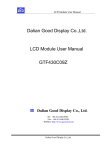
Operating, Installation and Service Instructions TOR MIR Direct- and Indirect-fired Fuel Oil/Diesel/ Kerosene Heaters TOR 67 WU TOR 115 WU TOR 175 WU MIR 37 WU MIR 55 WU MIR 85 WU ________________________________________________________________________________________________ 2 1. GENERAL SAFETY RULES READ INSTRUCTIONS CAREFULLY. READ AND FOLLOW ALL INSTRUCTIONS. PLACE INSTRUCTIONS IN A SAFE PLACE FOR FUTURE REFERENCE. DO NOT ALLOW ANYONE WHO HAS NOT READ THESE INSTRUCTIONS TO ASSEMBLE, LIGHT, ADJUST OR OPERATE THE HEATER. IF THE INFORMATION IN THIS MANUAL IS NOT FOLLOWED EXACTLY, A FIRE OR EXPLOSION MAY RESULT CAUSING PROPERTY DAMAGE, PERSONAL INJURY OR LOSS OF LIFE. SERVICE MUST BE PERFORMED BY A QUALIFIED SERVICE AGENCY. UNVENTED PORTABLE HEATERS USE AIR (OXYGEN) FROM THE AREA IN WHICH IT IS USED. ADEQUATE COMBUSTION AND VENTILATION AIR MUST BE PROVIDED. REFER TO INSTRUCTIONS. WARNING DO NOT STORE OR USE GASOLINE OR OTHER FLAMMABLE VAPORS AND LIQUIDS IN THE VICINITY OF THIS OR ANY OTHER APPLIANCE. WARNING FIRE, BURN, INHALATION, AND EXPLOSION HAZARD. KEEP SOLID COMBUSTIBLES, SUCH AS BUILDING MATERIALS, PAPER OR CARDBOARD, A SAFE DISTANCE AWAY FROM THE HEATER AS RECOMMENDED BY THE INSTRUCTIONS. NEVER USE THE HEATER IN SPACES WHICH DO OR MAY CONTAIN VOLATILE OR AIRBORNE COMBUSTIBLES, OR PRODUCTS SUCH AS GASOLINE, SOLVENTS, PAINT THINNER, DUST PARTICLES OR UNKNOWN CHEMICALS. WARNING COMBUSTION BY-PRODUCTS PRODUCED WHEN USING THIS PRODUCT CONTAIN CARBON MONOXIDE, A CHEMICAL KNOWN TO THE STATE OF CALIFORNIA TO CAUSE CANCER AND BIRTH DEFECTS (OR OTHER REPRODUCTIVE HARM). GENERAL HAZARD WARNING FAILURE TO COMPLY WITH THE PRECAUTIONS AND INSTRUCTIONS PROVIDED WITH THIS HEATER, CAN RESULT IN DEATH, SERIOUS BODILY INJURY AND PROPERTY LOSS OR DAMAGE FROM HAZARDS OF FIRE, EXPLOSION, BURN, ASPHYXIATION, CARBON MONOXIDE POISONING, AND/OR ELECTRICAL SHOCK. ONLY PERSONS WHO CAN UNDERSTAND AND FOLLOW THE INSTRUCTIONS SHOULD USE OR SERVICE THIS HEATER. IF YOU NEED ASSISTANCE OR HEATER INFORMATION SUCH AS AN INSTRUCTION MANUAL, LABELS, ETC. CONTACT THE MANUFACTURER. WARNING NOT FOR HOME OR RECREATIONAL VEHICLE USE WARNING YOUR SAFETY IS IMPORTANT TO YOU AND TO OTHERS, SO PLEASE READ THESE INSTRUCTIONS BEFORE YOU OPERATE THIS HEATER ________________________________________________________________________________________________ 3 THE ELECTRICAL SYSTEM TO WHICH THE APPLIANCE IS CONNECTED MUST COMPLY WITH ALL SAFETY REGULATIONS IN FORCE. A RESIDUAL CURRENT CIRCUIT BREAKER MUST BE PROVIDED ON THE MAIN DISTRIBUTION BOARD. UNPLUG THE HEATER BEFORE ATTEMPTING ANY SERVICE OR MAINTENANCE. ALWAYS CHECK THE POWER SUPPLY CABLE BEFORE USE. IT MUST NOT BE BENT, CRUSHED, OR ANYWAY DAMAGED. THE POWER SUPPLY CABLE MUST BE REPLACED ONLY BY QUALIFIED PERSONNEL. ONLY USE AN ORIGINAL POWER CABLE WITH A 3-PIN GROUNDED PLUG. DO NOT TOUCH THE EXHAUST GAS OUTLET. DANGER OF BURNS! 2. PRODUCT DESCRIPTION Mobile space heater with: closed combustion chamber and gas exhaust duct (indirect-fired models) open combustion chamber (direct-fired models) 3. TECHNICAL SPECIFICATIONS 3.1 Indirect-fired heaters Model # Firing rate (BTU/hr) Air Flow Rate (ft³/min) Fuel Types Fuel Consumption (gal/hr) Fuel Nozzle Efficiency (%) Noise Level at 2m (dB(A)) Voltage (V) Electrical Power (W) Current Rating (A) Weight (lb) Lenght (in) Width (in) Height (in) Flue Diameter (in) Tank Capacity (gal) Fuel Pressure (psi) Air Lock Setting MIR 37 WU 125,200 1180 0.88 0.65 60°H 87.1 75 460 7.0 154 47 24 31 6 14 175 1 MIR 55 WU 180,900 1470 #1-2 Fuel Oil / Diesel / Kerosene 1.28 1.00 60° H 87.1 73 115V 60Hz 1ph 460 7.0 178 54.8 27.6 32.7 6 26.5 175 2 MIR 85 WU 288,700 2650 2.04 1.50 80° W 88.5 73 800 12.5 282 68.0 29.5 40.4 6 36.0 175 3.5 3.2 Direct-fired heaters Model # Firing rate (BTU/hr) Air Flow Rate (ft³/min) Fuel Types Fuel Consumption (gal/hr) Fuel Nozzle Efficiency (%) Noise Level at 2m (dB(A)) Voltage (V) Electrical Power (W) Current Rating (A) Weight (lb) Lenght (in) Width (in) Height (in) Tank Capacity (gal) Fuel Pressure (psi) Air Lock Setting TOR 67 WU 227,000 1650 1.60 1.25 60°S 100 73 460 7 142 55.3 24.4 29.5 14 175 1.5 TOR 115 WU TOR 175 WU 396,500 607,000 2825 3240 #1-2 Fuel Oil / Diesel / Kerosene 2.80 4.28 2.25 80°W 3.50 80°S 100 100 73 76 115V 60Hz 1ph 800 1100 12.5 17.5 223 264 66.1 76.3 27.2 29.6 35.4 40.8 26 36 175 175 3.5 9.0 ________________________________________________________________________________________________ 4 4. INSTALLATION INSTRUCTIONS 4.1. General instructions THE INSTALLATION OF THE EQUIPMENT SHALL BE IN ACCORDANCE WITH THE REGULATION OF AUTHORITIES HAVING JURISDICTION AND CSA B139. The heater must be operated only by properly trained personnel. The manufacturer’s instructions must be followed. The heater must be installed and operated so that people are not exposed to dangers deriving from exhaust gases, from the hot air flow and in such a way that no fire risks exist. It is forbidden to install the heater in the surroundings of flammable materials, combustible products, or in explosive atmospheres. When an indirect-fired heater connected to a flue pipe is used in a closed room, provide a minimum opening area of 1 ft³ per US gallon capacity at the unit level. When a direct-fired heater - or an indirect-fired heater not connected to a flue pipe - is used in a closed room, provide a minimum opening area of 3 ft2 per US gallon capacity at the unit level and a continuous, natural air circulation through windows and doors. For the use of the heater the general and special fire safety regulations in force in all fields of applications must be followed. In any case the following minimum safety clearances from flammable materials or objects in the surroundings of the heater must be ensured: Sides: Top: Flue pipe: 2 ft (610 mm) 5 ft (1520 mm) 3 ft (915 mm) Air inlet: Air outlet: 2 ft (610 mm) 10 ft (3050 mm) Floors and ceilings must be made of fireproof materials in the place where the heater is operated. The air inlet and outlet must never be blocked for any reason. Install the heater on a flat, level floor in a steady position. It is forbidden to connect direct-fired heaters to air ducts. 4.2 Assembling the heater Before operating the heater, assemble axle, wheels and lower support following the diagram below: ________________________________________________________________________________________________ 5 Maintenance and checks Depending on the operational conditions, usually every year, the heater should be checked by qualified personnel. Prior to start-up, the user must check for any evident non-compliance with rules of use, safety and protection. 5. INSTRUCTIONS FOR USE 5.1 Start-up 1 2 3 4 The heater is factory set for operation without room thermostat. If operation with room (remote) thermostat is desired, remove the socket cover (Fig. 1 nr. 1) and insert the thermostat plug into the socket. Fig.1 Fill the tank with fuel of proper type. Connect the supply plug to a 115V ~ 60 Hz single phase earthed socket. The green lamp indicates that the heater is powered. WARNING: THE APPLIANCE MUST BE GROUNDED Indirect fired heaters Correct Incorrect Connect the heater to a flue pipe or to an exhaust duct. To get a proper draught (at least 0,1 mbar) in the flue pipe the exhaust gas path must rise. Avoid any elbows and bends in the first part of the flue pipe for at least 3 m. For operation of heater in closed rooms without flue refer to the instructions for installation (par. 4) If a remote thermostat is used, set it on maximum temperature. Turn switch to position “ON” Set the desired temperature on room thermostat. Caution heaters) (indirect-fired When this heater is connected to a flue pipe, the flue pipe shall terminate in a vertical section at least two feet long and sufficient draft shall be created to assure safe and proper operation of the heater. Where back drafts may occur a vertical cap should be used on the exit from the flue pipe. Horizontal runs of the flue pipe should have a rise 1 in 10 away from the heater 5.2. Reset after lockout – Safety air pressure switch The heater is equipped with a Reset pushbutton. When the heater locks out, the red lamp on the pushbutton (fig. 1 n°2) lights up. In this case push the Reset button (see also the par. “Troubleshooting”) to restart the heater. The heater is also equipped with an air pressure switch that senses the airflow pressure and locks the heater out in the event of unit overheating. If this occurs, detect and eliminate the cause of overheating before using the heater again. Have the heater inspected by a qualified technician if required. See point above for resetting. 5.3. Shut down. ________________________________________________________________________________________________ 6 Set switch to “OFF” to shut the flame off. The fan will go on rotating for 1 min 45 sec to cool the heater down. The fan motor will automatically stop at the end of the aftercooling time, then the unit can be disconnected from mains. Never disconnect the power plug to stop the heater while in operation The big amount of heat produced could damage the components: allow cooling sequence to take place 6. MAINTENANCE Before carrying out any maintenance operation, disconnect the power plug. Maintenance must be carried out by qualified personnel (see also par. 7) The appliance must be thoroughly cleaned once a year to ensure good combustion and long life. Clean periodically the oil spraying nozzle and its filter; the oil pump filter the main fuel filter cartridge the ignition electrodes the fan blades the inside of the appliance, using compressed air the flame sensor with a mild detergent Periodically check cables and electrical connections. Check the oil filter and replace if necessary. 7. TROUBLESHOOTING TROUBLE Heater does not start CAUSE No power Faulty cable/connections Burnt fuse Room thermostat set too low SOLUTION Check main distribution board and power supply line Check/have cable replaced by a qualified electrician Check and replace if required Set room thermostat on a higher temperature Room thermostat socket cap not Insert cap into the thermostat socket inserted Heater in lock-out mode Reset Heater starts, flame ignites but then Dirty or faulty flame sensor Clean or replace heater locks out Faulty burner control unit Contact service personnel Heater starts, flame does not ignite and Clogged nozzle Clean or replace then heater locks out Flame sensor receives an external light Check for external lights (sun, lamps, signal during ignition sequence etc.) Faulty burner control unit Contact service personnel No fuel Fill tank Ignition fault, dirty or incorrectly spaced Clean electrodes, contact service electrodes personnel if required Heater starts, but combustion is not Dirty or blocked nozzle Clean or replace good Clogged filters Clean or replace Leakes in fuel circuit Check and eventually replace Oil pump provides low pressure Contact service personnel Insufficient combustion air Wrong air lock setting Insufficient ventilation air Contact service personnel Heater stops as the air pressure switch The appliance has overheated See par. 5.2. functions Faulty pressure switch Contact service personnel ________________________________________________________________________________________________ 7 8. WIRING DIAGRAM P TOR 67 WU, TOR 115 WU MIR 37 WU, MIR 55 WU, MIR 85 WU black EV brown dk. blue M TR TRcont. M18 M12 M10 M7 FR M16 M11 L M14 white PL N green green Fuel Solenoid Valve Ignition Transformer Motor Warning Lamp Air Pressure Switch Fuse Flame Sensor Reset Button Switch Remote Thermostat Heated Filter Relay black M2 TH black IN M4 M3 L FS PL M19 white M1 green M6 PL N SL M8 red FC IN 2 1 FC EV TR M SL PA FS FC PL IN TH FR R white black M5 Fuel Solenoid Valve Ignition Transformer Motor Warning Lamp Air Pressure Switch Fuse Flame Sensor Reset Button Switch Remote Thermostat Heated Filter M15 M9 EV brown white black M M17 M13 FR black 2 black 1 TR lt. blue black PA EV TR M SL PA FS FC PL IN TH FR black brown 3 PL 1 3 TH 2 white Optional TOR 175 WU P EV white black PA TR FR M M17 M13 black TR black M15 M9 EV white black R white black white black white M TRcont. M18 M12 M10 M7 FR M16 M11 L M14 white white N black black FC M1 green M6 green green M5 PL 2 1 M2 TH M3 IN M4 L FS PL M19 red PL black white FC N SL M8 IN black brown 3 PL 1 3 TH 2 white Optional ________________________________________________________________________________________________ 8 ________________________________________________________________________________________________ 9 ________________________________________________________________________________________________ 10