1
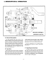
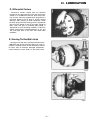
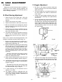
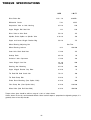
Telephone (925) 454-9500 Fax (925) 454-9501
151 Lawrence Drive, Livermore, CA 94551
www.fabcoautomotive.com
TABLE OF CONTENTS
I.
Description and Operation
A.
B.
C.
II.
General Description
Operation
Operation Instructions
V.
2
2
2
A.
B.
C.
D.
E.
Wheel Bearings
Universal Joints
Kingpin Bearings
Differential Carrier
Steering Tie Rod Ball Joints
3
3
3
4
4
Ill. Axle Adjustment
A .
B.
C.
D.
E.
F.
G.
H.
IV.
General
Wheel Bearing Adjustment
Kingpin Adjustment
Steering Stop Adjustment
Camber Adjustment
Caster Adjustment
Toe-In Adjustment
Brake Adjustment
5
5
5-6
6
7
8
8
8
Steerable Drive End Disassembly
A.
B.
C.
D.
E.
F.
G.
H.
I.
J.
K.
L.
M.
N.
O.
General Precautions for
Disassembly
Brake Drum, Hub and
Wheel Bearing Disassembly
Brake and Wheel Spindle
Disassembly
Spindle Yoke Removal
Removal of the Outboard Section
of the Steerable Drive End
Inner Axle Shaft Removal
Lower Kingpin Bracket and
Kingpin Removal
Lower Kingpin Bearing Removal
Upper Kingpin Removal
Steering Arm Removal
Upper Kingpin Removal
Inner Axle Seal Removal
Outer Axle Seal Removal
Outer Drive Yoke Roller
Bearing Removal
Universal Joint Disassembly
A . Choice of Cleaning Methods
B . Drying and Corrosion Inhibition
C . Inspection
VI.
Lubrication
9
Cleaning and Inspection
Steerable Drive End Assembly
A.
General Precautions for
Reassembly
B. After Partial Disassembly
C . Suspension Yoke Assembly
D . Spindle Yoke Assembly
E . Lower Kingpin Bracket
Installation
F . Spindle Yoke to Suspension
Yoke Assembly
G . Brake Assembly Installation
H. Wheel Hub Assembly
I.
Outer Drive Yoke and Outer
Drive Axle Shaft Assembly
J.
Universal Joint Assembly
K . Brake Actuator Chamber
Installation
L . Steering Arm Assembly
M . Tie Rod Assembly
N . Final Assembly
A.
10
11
B.
12
12
13
13
13
13
13
15
15
15-16
17
17
17
17
18
19
19
19
19
19
VII. Differential Carrier Removal and Installation
9
11-12
12
14
14
14
Removal of Differential Carrier
from Axle
Installation of Differential
Carrier to Axle
VIII. Torque Specifications
Service Bulletin
20
20
21
22-24
PARTS MANUAL
SDA
SDA
SDA
SDA
13
13
12
16
18
21
25-32
33-40
41-47
49-55
Additional Service Manuals
Single Reduction Differential Service Manual
Air Brake Service Manual
Hydraulic Brake Service Manual
SDA-12-16-18-21-2M (12/89)
—1—
I. DESCRIPTION & OPERATION
A. General Description
The Fabco Steerable Drive Axle consists of four
major assemblies. The axle housing is the structural
backbone. Steerable drive ends are attached to each
end of the housing. A differential carrier assembly
bolts into the center of the housing. A steering connecting tie rod joins between the right and left steerable drive ends. A steering arm is provided (usually on
the left steerable drive end) for connection into a vehicle’s steering system. It may be equipped with right
hand or dual steering arms.
B. Operation
Driving forces are put into the axle at the pinion
yoke on the differential carrier; they pass through the
differential to the inner axle shafts and the inner drive
yoke of the universal joint; they then pass into the
outer drive yoke and the outer axle shaft which connects to the wheel hub and rotates the wheel.
—2—
When steered, the outer section of each steerable
drive end turns about the kingpin centerline. The universal joint, centered on the kingpin centerline, allows
driving forces to turn with the steered wheel ends.
The axle is equipped with air or hydraulic brakes.
The brake shoes expand to contact conventional
brake drums.
C. Operating Instructions
In conditions where the vehicle’s rear wheels might
spin, such as sand, loose dirt, mud, snow, ice or
ascending grades, the front drive axle can be shifted
into operation for improved traction. Engagement can
be made at any vehicle speed, unless the rear wheels
are spinning. Engagement is best accomplished
while the engine is pulling lightly.
II. LUBRICATION
Recommended Lubricants
LUBRICANT
ABOVE 32°
BELOW 32°
Gear Oil
MIL-L-2105 B
SAE 140
MIL-L-2105 C
80W-140
MIL-L-2105 B
SAE 90
MIL-L-2105 C
80W-90
Chassis Grease
MIL-G-10294
MIL-G-10294
Wheel Bearing Grease
NLGI Grade #2
NLGI Grade #2
Wheel Bearing Oil
Use same as recommended for differential
A. Wheel Bearings
Wheel bearings require cleaning, inspection, packing
with grease or an oil change at each brake re-line. Wheel
bearings should be lubricated in accordance with the
vehicle manufacturers recommendations. They may
either be grease packed or oil lubricated. A ¼” pipe
plug (See fig. 2) is located under the hubcap in the outer
axle shaft flange. Oil filled wheel hubs should be filled
to the level of this plug when it is in a position on the
axle horizontal centerline. When using grease to pack
the bearings, grease both inner and outer wheel
bearings. In addition to greasing both inner and outer
wheel bearings, be sure to grease the carrier bearing
for the outer drive yoke. By removing the cross and
bearing U joint and outer drive yoke, you can hand pack
the outer drive yoke carrier bearing. When packing the
carrier bearing be sure not to damage the outer drive
yoke seal.
Fig. 2
B. Universal Joints
Universal joints should be lubricated at each chassis
lubrication (approximately 1,000 mile intervals).
Vehicles operated with the joints submerged must be
lubricated at more frequent intervals. Grease the universal joints until grease seepage occurs at the caps. If
grease does not seep out of all four caps, rotate universal joints 180° and reapply grease.
C. Kingpin Bearings
Kingpin bearings should be lubricated at each
chassis lubrication (approximately 1,000 mile intervals).
To ensure thorough lubrication, the front axle should
be raised slightly to relieve weight. The lower kingpin
lube fitting is located in the lower suspension yoke.The
upper kingpin fitting is either on the front or rear of the
upper kingpin bracket (See fig. 3).
Fig. 3
—3—
II. LUBRlCATlON
D. Differential Carriers
Differential carriers should have the lubricant
changed at the same intervals as the rear axle on the
vehicle, or at 10,000 mile intervals. Drain while lubricant is warm. Clean the magnetic drain plug when it is
removed. Remove the fill plug to ensure quicker
drainage. Allow housing to drain completely. Install
the drain plug and fill the housing with the appropriate
gear oil to the bottom of the fill plug hole. Check for
leaks. SAE 140 gear oil (meeting Mil-L-2105B) is
appropriate for most operating conditions. Follow the
vehicle manufacturers recommendations for the rear
axle and apply them to the front axle under other
conditions.
E. Steering Tie Rod Ball Joints
Fig. 4
Steering tie rod ball joints should be lubricated every
1,000 miles with chassis lubricant (See fig. 3, Page 3.)
Check the steering system at each lubrication. Inspect
for loose, bent or otherwise damaged components.
Careful attention to such detail is a vital safety factor.
Fig. 5
Fig. 6
—4—
III. AXLE ADJUSTMENT
A. General
C. Kingpin Adjustment
1. The front of the vehicle should be raised and
properly supported. The front wheels should be
taken off the axle.
Adjustments may be necessary after an accident, in
response to and to correct steering problems, tire
wear problems or as a part of the reassembly process
after a thorough inspection.
2. The lower kingpin jam nut should be loosened and
the lower kingpin ball should be backed down
until it stops.
B. Wheel Bearing Adjustment
1.
Raise the front of the vehicle with a jack and
secure vehicle with jackstands of suitable
capacity.
2.
Remove front wheels from vehicle.
3.
Remove the brake drum. (Disc style wheels only.)
3.
Loosen the upper kingpin adjusting screw jam
nut. Back off the adjusting screw approximately
four (4) turns.
4.
Place a small bottle jack under the wheel end (See
fig. 6A). Raise the wheel end until the upward
movement stops. By feeling the gap between the
lower kingpin bracket and the suspension yoke
(See fig. 6B), you will be able to determine when
upward movement stops. You have now seated
the upper kingpin.
4. With the end turned to full steering lock, remove
the bolt and washer retaining the outer drive yoke.
(See fig. 14, Page 9.)
5.
Remove the two cap screws that hold the hub cap
on, then proceed to remove the nuts from the
outer axle shaft drive studs.
6. The flange should be loose enough to remove by
hand. If not, use suitable bolts in the extractor
holes to remove the outer axle shaft. (See fig. 15,
Page 9.)
Note: If oil is used for wheel bearing lubrication, care
should be exercised to protect brake linings, etc.
7.
Fig. 6A
Remove the wheel bearing lock nut (See fig. 4,
Page 4) and lockwasher from spindle. Loosen
wheel bearing adjustment nut.
8. Tighten wheel bearing adjusting nut while turning
the hub, back off ½ turn and then tighten to 50
ft. Ibs. torque. (See fig. 4, Page 4.) Back off ¼ turn.
Install the wheel bearing lockwasher with tang in
the spindle keyway and one side or the other
toward the bearing locknut in such a way as to fit
over dowel.
Install the outer locknut and torque to specification. With the locknut properly tightened, the
wheel hub should rotate freely.
Fig. 6B
9 . Apply a bead of liquid sealant to outer axle shaft
flange. (See Service Bulletin 738 407, Page 22.)
5.
10. Reinstall both outer axle shaft nuts and outer drive
yoke washer and bolt. Tighten to specifications.
(Figure 6, Page 4.)
Screw the lower kingpin ball stud upward until the
ball makes contact with the bushing. You will feel
a slight resistance in turning the ball stud. (See
fig. 6C.)
Ressemble the outer axle shaft, being careful
to align the splines on the outer axle shaft with
the outer drive yoke. (Fig. 5, Page 4.)
11. If wheel bearings are oil lubricated, refer to
Section II, A to refill.
12. The kingpins should be readjusted after any
loosening or removal and reassembly of the upper or lower kingpin brackets, replacement of
kingpin bushings, etc.
Fig. 6C
—5—
III. AXLE ADJUSTMENT
6. Place a stack of feeler gauges in the gap between
the lower kingpin bracket and the suspension
yoke. The gauges should fit snugly. Continue to
screw the lower kingpin ball stud upward untill the
feeler gauge begins to fall (move downward). (See
fig. 6D.)
Fig. 6
7.
Fig. 7
Remove the feeler gauge from the opening and
back off the lower kingpin ball stud ¼ turn. You
have now seated the lower kingpin. Tighten the
jam nut to 400 lb. ft. while restraining the lower
kingpin ball from turning.
8. Screw the upper kingpin stop bolt downward until
it touches the top of the upper kingpin ball. Back
the adjusting screw off ¼ turn. Restrain the screw
while tightening the locknut to 45 lb. ft. (See fig.
6E.)
Fig. 8
3. The steering stop is the lower rear, upper kingpin
bracket mounting bolt (See fig. 7). Adjustment is
made by the installation of a number of washers
under this bolt’s head (See fig. 8). The purpose of
the stop is to protect the universal joint and the
brake chamber from hitting another part in a full
turn of the steering.
9. Remove the small bottle jack, a slight up and
down movement is normal.
4. Turn the steering to put the axle first in the full left
turn condition. (See fig. 9, Page 7.)The head of the
stop bolt should stop the turn before any of the
rotating parts in the left hand steerable drive end
interferes with another part. The brake chamber
on the right end should not hit the suspension
yoke. Turn the steering to the right and check the
corresponding conditions (See fig. 8 and 10.)
10. The kingpins should be readjusted after any
loosening or removel of the upper or lower
kingpin brackets, replacement of kingpin
bushings, etc.
D. Steering Stop Adjustment
1.
Adjust the tie rod. See section III-G.
2.
Steering stop adjustment is made at the factory
— needs no further action, unless a major part
such as the suspension yoke, spindle yoke,
kingpin bracket or the like has been replaced.
NOTE: POWER STEERING STOPS IN THE
VEHICLE STEERING GEAR SHOULD NOT
ALLOW THE APPLICATION OF POWER TO
THE STEERING WHEN THE STEERABLE
DRIVE END IS IN THE FULL TURN CONDITION.
—6—
III. AXLE ADJUSTMENT
Fig. 11
Fig. 9
Fig. 12
Fig. 10
E. Camber Adjustment
1.
Refer to this section, part B, steps 1 and 2,
2.
Adjustment is made by the addition or subtraction of shims.
3. Loosen the four bolts at the upper kingpin
bracket, loosening bracket from the spindle
yoke. Remove only the top two bolts.
4. Remove or install shims as necessary to
achieve the desired camber. (See figs. 11 and
12.)
5.
6.
Typical setting is ½° positive, accomplished by
factory installation of a shim between the upper
kingpin bracket and the spindle yoke. Consult a
tire specialist for specific recommendations.
Re-install bolts and tighten to the specific torque.
(See fig. 13.)
Fig. 13
7.
—7—
Readjust the kingpin, referring to section III, Part
C, Page 5.
III. AXLE ADJUSTMENT
F. Caster Adjustment
H. Brake Adjustment
Caster is set by the vehicle manufacturer and can
be adjusted only by shims between the axle spring
seat and the spring. Changing the caster will change
the pinion angle and may affect the operation of the
front drive shaft.
Brake adjustment is made automatically. Make the
initial adjustment by driving the air braked vehicle
forward and applying the brakes. Continue applications until the shoe to drum clearance is between
.015” and .030”. (Refer to the brake service manual for
additional information.)
G. Toe-In Adjustment
It is not recommended to raise the front of the truck
to check toe in.
An expandable toe in alignment bar is recommended when checking and setting toe in on Fabco axles.
1.
Turn tie rod tube with a pipe wrench to adjust
toe-in. Set tie rod length until front measurement
is 0 to 1/8” less than rear measurement. If the
vehicle has a full-time front drive system (proportioning differential), alignment should be 0-1/8”
more in front than in rear, for toe-out. Consult a
tire specialist for a specific recommendation if
specialized tires are used.
2.
Tighten tie rod clamp bolts to correct torque. Roll
vehicle forward at least a distance equal to four
turns of wheels and re-check toe-in. Repeat
procedure if necessary to achieve final toe-in
dimension.
—8—
IV. STEERABLE DRIVE END DISASSEMBLY
A. General Precautions for
Disassembly
6.
IMPORTANT: READ THIS SECTION BEFORE
STARTING THE DISASSEMBLY PROCEDURES.
1.
The flange should be loose enough to remove
by hand. If not, use suitable bolts in the extractor
holes to remove the outer axle shaft. (See fig. 15).
Note: If oil is used for wheel bearing lubrication,
care should be exercised to protect brake linings, etc.
Follow each procedure closely in each section,
making use of both text and pictures.
2. The outside of the unit should be carefully
cleaned before starting the disassembly. If
steam cleaning, ensure that breather and air
fittings are covered to prevent water from entering assembly.
3. Cleanliness — Provide a clean place to work. It
is important that no dirt or foreign material enters
the unit during repairs.
4.
Refer to the Exploded Views located in the parts
section as a guide to disassembly.
5.
Assemblies — When disassembling the various
assemblies, lay all parts on a clean bench in the
same sequence as removed. This procedure
will simplify reassembly and reduce the possibility of losing parts.
Fig. 14
6. Bearings — Carefully wash and relubricate all
bearings as removed and protectively wrap until
ready for use. Remove bearings with pullers
designed for this purpose, or in a manner which
will not damage those bearings that will be
reused.
7.
When necessary to apply a force to remove a
part, use of a puller or press would be preferred.
However, sometimes it may be necessary to use
a soft hammer or bar.
B. Brake Drum, Hub and Wheel
Bearing Disassembly
1.
Raise the front of the vehicle with a jack and
secure vehicle with jackstands of suitable
capacity.
2.
Remove front wheels from vehicle.
3.
Remove the brake drum. (Disc wheel style hubs
only).
4.
With the end turned to full steering lock remove
the bolt and washer retaining the outer drive
yoke. (See fig. 14).
5.
Remove the nuts from the outer axle shaft drive
studs.
Fig. 15
7.
Remove the wheel bearing lock nut (See fig. 16,
Page 10) and lockwasher from spindle. Loosen
wheel bearing adjusting nut.
8.
Rock hub lightly to loosen the outer wheel bearing cone. Remove the cone and protect it from
dirt. If wheel bearings are oil lubricated, some oil
may fall on the brake shoe when the hub is
removed in the next step, unless suitable protection is used.
—9—
IV. STEERABLE DRIVE END DISASSEMBLY
9.
Lift the hub (or hub and drum assembly) off the
spindle (See fig. 17) using care to avoid damage
to the bearing surfaces and to the threads. Wipe
off any oil that may have reached the brake shoe
before it reaches the lining.
10.
Do not remove the axle shaft studs unless
replacing them.
11.
Remove the hub seal from the hub and discard.
12.
Remove the inner wheel bearing cone and protect it from dirt.
13.
Cover the spindle with a clean shop rag to protect it from damage.
14.
Press wheel bearing cups from hub, if replacement is necessary.
THIS IS THE LIMIT OF WHAT MAY BE CALLED
ROUTINE DISASSEMBLY. IT ALLOWS ACCESS TO
THE BRAKES FOR RELINING AND TO THE WHEEL
BEARINGS FOR REPACKING. DISASSEMBLY
BEYOND THIS POINT MIGHT BE REQUIRED TO
REPLACE DAMAGED OR BROKEN PARTS.
Fig. 17
C. Brake and Wheel Spindle
Disassembly
1.
12-point capscrews retain the brake assembly
and the spindle to the spindle yoke (See fig. 18).
Make provisions for supporting the brake
assembly in a place that will protect the brake
hose or disconnect the brake hose. Remove the
brake assembly after removing the capscrews.
2.
Hold the spindle (See fig. 19) tap it with a soft
hammer and it should separate from the spindle
yoke.
3.
Remove outer drive yoke from spindle yoke.
Fig. 18
Fig. 19
Fig. 16
—10—
IV. STEERABLE DRIVE END DISASSEMBLY
D. Spindle Yoke Removal
1.
Perform steps B and C, page 9 and page 10.
2. Disconnect the steering rod by removing the
cotter pin, castle nut and then while prying
between the tie rod end and the tie rod arm,
sharply strike the side of the tie rod arm radially
to the tie rod end tapered stud. Disconnect the
brake hose.
3.
Remove four capscrews (See fig. 20) that retain
the universal joint cross and bearing to the outer
drive yoke.
4. Support the spindle yoke while removing the
four capscrews at the upper kingpin bracket.
(See fig. 13, Page 7.)
5.
Lower the spindle yoke and at the same time
rotate the top outward. (See fig. 21.) This should
allow the lower kingpin ball to come out of its
socket in the suspension yoke. The spindle yoke
can then be moved away from the axle.
Fig. 21
E. Removal of the Outboard Section
of the Steerable Drive End
NOTE: After following this procedure, the outboard section of the end may be disassembled
on the bench by following IV. B, C and D.
1.
Perform Items 1 and 2 of Step B, Page 9.
2.
Rotate the brake drum to position the outer drive
yoke horizontally.
3.
Unbolt the universal joint cross and bearing from
the outer drive yoke. (See fig. 20.)
4.
Attach the outboard section of the steerable
drive end to a transmission jack that is equipped
to handle the assembly. (See figs. 22 and 23.)
Fig. 22
Fig. 20
Fig. 23
—11—
IV. STEERABLE DRIVE END DISASSEMBLY
5.
Disconnect the steering tie rod by removing the
cotter pin, castle nut and then, while prying
between the tie rod end and the tie rod arm,
sharply strike the side of the tie rod arm radially
to the tie rod end tapered stud.
6.
Disconnect the brake hose.
7.
Remove the four bolts that hold the upper kingpin bracket to the spindle yoke.
8.
Lower the transmission jack about two inches
and roll the outer section of the steerable drive
end away from the axle.
F. Inner Axle Shaft Removal
1.
Perform only step E Page 11, then pull the axle
shaft and universal joint from the axle housing.
(See fig. 24.)
2.
Or after steps B, C, and D, pull the axle shaft and
universal joint from the axle.
Fig. 24
G. Lower Kingpin Bracket and
Kingpin Removal
1.
The lower kingpin ball stud and the lower kingpin
bearing are exposed for inspection after steps B,
C, and D or after step E alone. (See fig. 25.)
Back off lower kingpin lock nut. Remove four
nuts and washers retaining the lower kingpin
bracket and tie rod arm to the spindle yoke. The
bracket may now be removed.
2.
Fig. 25
Screw the kingpin stud from the bracket.
H. Lower Kingpin Bearing Removal
After Section IV-E, only if the bearing is being
replaced, drive the bearing out of the suspension yoke
by pushing on the lower kingpin bearing plate.
Fig. 26
—12—
IV. STEERABLE DRIVE END DISASSEMBLY
I. Upper Kingpin Removal
M. Outer Axle Seal Removal
After Section IV-E, remove locknut from the bottom
of the upper kingpin. Use a jack or jack screw to pry
between the stud and the lower portion of the suspension yoke to force the ball stud from its tapered hole.
After IV-D or E, Page 11 use a standard puller to
remove the seal or refer to IV-O.
J. Steering Arm Removal
N. Outer Drive Yoke Roller Bearing
Removal
1.
Disconnect brake line connection that may be
attached to the steering arm.
With the spindle removed (section IV-D) and after
removing the seal (section IV-M), the bearing can be
pushed from the spindle yoke.
2.
Disconnect the steering drag link if so desired —
by applying a force between the drag link end and
the steering arm and then striking the steering
arm radially to the tapered ball connection. Avoid
driving on the end of the tapered ball, or nut
screwed thereon, as this will severely damage the
end of the tapered ball before the parts separate.
O. Universal Joint Disassembly
3.
Remove the four locknuts from the steering arm
studs and remove the arm.
K. Upper Kingpin Removal
1.
The universal joint may be disassembled without
any other disassembly or after step IV-D, or IV-E.
Remove eight capscrews that attach the cross and
bearing assembly to drive yokes. (See fig. 20, Page 11.)
Remove the cross and bearing. (See fig. 27). Remove
the capscrews from the center of the drive yokes and
remove the drive yokes. The outer drive yoke may require some prying before it comes off the outer axle
shaft.
Remove only if replacing with a new part.
2. After removing the upper kingpin bracket from the
steerable drive end assembly, use a small drift to
tap the bearing out of the upper kingpin bracket.
L. Inner Axle Seal Removal
1.
Do not remove the seal unless it is to be replaced
by a new seal assembly.
2.
The suspension yoke must be off the axle housing before the seal assembly can be removed.
After IV-F, proceed as follows:
3.
Remove suspension yoke from the axle housing
by removing eight locknuts and hardened
washers. (See fig. 26.)
4.
Drive the seal from the suspension yoke with a
suitable drift.
Fig. 27
—13—
V. CLEANING AND INSPECTION
A. Choice of Cleaning Methods
C. Inspection
1.
Steam may be used for external cleaning of
completely assembled units. Care must be
taken to ensure that water is kept out of the
assembly by tightly closing breather caps and
other openings.
2.
Rough parts such as housings, which are too
large to conveniently clean with solvents, may be
immersed in a hot solution tank containing a mild
alkaline solution. Parts cleaned in hot solution
tanks must be rinsed thoroughly to prevent
damage by traces of alkaline material.
3.
Parts with ground or polished surfaces, such as
bearings and shafts, should be cleaned with
emulsion cleaners or petroleum solvents. Alkaline hot solution tanks may damage the
machined surfaces and such cleaning methods
should be avoided.
Prior to reassembly, parts which are to be reused
must be carefully inspected for signs of wear or damage. Replacement of such parts can prevent costly
downtime at a future date.
All bearing surfaces, including ball bearing assemblies and roller bearing cups and cones, should be
examined for pitting, wear, or overheating. Shafts may
be nicked and marred, or may have damaged threads.
Parts which show any signs of damage should be
repaired or replaced.
B. Drying and Corrosion Inhibition
Soft, clean shop towels should be used to dry parts
after cleaning. Compressed air may be used to clean
accessible areas of large parts such as the housing.
Bearings should not be spun dry with compressed air,
as the lack of lubrication may cause damage to the
mating surfaces.
Dry parts should be immediately coated with a light
oil or corrosion inhibitor to prevent corrosion damage.
Parts which are to be stored should also be wrapped
in heavy waxed paper.
—14—
VI. STEERABLE DRIVE END ASSEMBLY
A. General Precautions for
Reassembly
IMPORTANT: READ THIS SECTION BEFORE
STARTING THE REASSEMBLY PROCEDURES.
1.
Gaskets — Use liquid sealant per Service Bulletin 738 407, Page 22.
2.
Differential Mounting Bolts — To prevent oil
leakage, use Permatex form-a-gasket #2 pliable
setting sealant or equal on all threads. See
torque rating chart for recommended torque,
Section VIII.
3.
Assembly — Refer to the parts section as a
guide to reassembly.
4.
Initial Lubrication — Coat all splines and seals
with Lubriplate during installation to provide
initial lubrication, preventing scoring and galling.
5.
Bearings — Use of flanged-end bearing drivers
is recommended for the installation of bearings.
These drivers apply force to inner or outer races
of bearing, preventing damage and maintaining
alignment with shaft and bore.
6.
Seals — Use a flanged type guide or driver to
install seals. Use of a soft hammer or a soft drift
can be made if care is exercised.
Fig. 28
B. After Partial Disassembly
Reassembly after partial disassembly should generally reverse the disassembly procedure.
C. Suspension Yoke Assembly
1.
Press eight studs into the suspension yoke.
2.
Apply liquid sealant or gasket cement to the
outer edge of the inner drive yoke seal assembly. (See fig. 28). Press inner drive yoke seal
assembly into suspension yoke with an installation tool; (See fig. 29 and 30). Remove excess
sealant.
3.
Insert the lower kingpin bearing plate with the
large end of the lube fitting tapered hole toward
the top of the suspension yoke. Press the lower
kingpin bearing into place in an arbor press or use
a push plate and a C-clamp. Do not use the
kingpin ball stud to press in the bearing. Lightly
lubricate the bearing and install the o-ring.
Fig. 29
Fig. 30
-1
-15
5-
VI. STEERABLE DRIVE END ASSEMBLY
4. Apply a bead of liquid sealant to the axle housing
flange. (See Service Bulletin 738 407, Page 22.)
Install the suspension yoke with hardened
washers and locknuts. Tighten to specified
torque.
5.
Install a new o-ring and a new upper kingpin bearing (if needed) into the upper kingpin bracket. Apply a light coat of lubricant to the inside of the
socket and to the ball section of the upper kingpin
ball stud. Insert the ball stud through the bearing
and bracket and into the tapered hole in the
suspension yoke. Install the plain washer and the
locknut. Tighten to the specified torque.
(For the SDA-12.)
6.
Assemble the inner axle yoke spacer ring on the
inner axle shaft against the shoulder behind the
spline. Install the inner drive yoke, (without the
pressed-on bearing race) onto the spline.
(For SDA-16, 18, 21 refer to item 47A, Page 39.)
Fig. 32
Fig. 31
7.
Install the short (1-3/4 long) bolt into a new sealing washer, through the retaining washer, and
into the shaft end, tightening to specified torque.
(See fig. 33).
8.
Apply lubricant to the inner drive yoke hub area.
Insert the proper inner drive yoke shaft assembly
through the suspension yoke. (See fig. 24, Page
12.) CAUTION MUST BE TAKEN TO AVOID
DAMAGING THE INNER DRIVE YOKE SEAL
ASSEMBLY. Rotate the inner drive yoke shaft
assembly until it engages the side gears on the
differential assembly, continue to slide the shaft
inward until it engages the seal assembly. Care
should be exercised to prevent damage to the
primary seal lip and to insure the drive yoke hub
is seated in the bronze bearing portion of the seal
without distorting the large rubber diaphragm
section of the floating seal.
Fig. 33
Fig. 34
-16 -
VI. STEERABLE DRIVE END ASSEMBLY
D. Spindle Yoke Assembly
1.
Pack the roller bearing with the proper lubricant
and press into place in the spindle yoke.
(See fig. 35.)
2.
Coat the outside circumference of the outer drive
yoke seal with liquid sealant. Press the seal into
place in the spindle yoke. (See fig. 36).
3.
Rest the spindle yoke with its inboard side down.
Install the lower kingpin mounting studs.
E. Lower Kingpin Bracket
Installation
1.
Screw the lower kingpin ball stud into the lower
kingpin until it just bottoms. Start the lower
kingpin ball stud jam nut onto the stud.
2.
The lower kingpin brackets with integral tie rod
arms are handed. The left arm goes on the left
steerable drive end and will position the tie rod to
the rear when installed on the axle.
3.
Position the proper bracket on the studs or bolts,
whichever is used, projecting through the spindle
yoke. Install the hardened washers and locknuts.
Tighten to the specified torque. (See fig. 25, Page
12.)
F. Spindle Yoke to Suspension
Yoke Assembly
1. With the spindle yoke upright, position the outer
drive yoke horizontally. If the spindle yoke
assembly includes the brakes and wheel hub it
should be attached to and supported by a suitable
jack or hoist. Position the lower kingpin ball (well
lubricated) under the lower kingpin ball socket in
the suspension yoke. (See fig. 21, Page 11.) The
spindle yoke assembly must be tilted slightly outward at the top to allow the ball stud to enter its
socket.
2.
Raise the spindle yoke assembly until the ball
stud enters the socket. Align the upper kingpin
mounting holes with the corresponding holes in
the spindle yoke.
3.
Install only three bolts. (See fig. 13, Page 7.) The
lower rear bolt is the steering stop bolt. Washers
under the fourth bolts head will limit the maximum
turn angle on the steerable drive end. The bolts
should pass through the camber adjusting shim
or shims. (See fig. 13, Page 7.) The same number
of washers and the same shims should be reused in a reassembly of parts that have previously
been together. Also refer to Section Ill-D and E.
(Pages 6, 7.) Tighten locknuts to specifications.
G. Brake Assembly Installation
Fig. 35
Fig. 36
-17 -
1.
Apply a bead of liquid sealant to the spindle flange
or the spindle yoke. (See Service Bulletin 736 407,
Page 22.) Position the spindle on the spindle yoke,
piloting on the roller bearing outer race, aligning
the bolt holes, and orienting the wheel bearing adjusting lock-washer keyway to face upwards.
Position the brake assembly on the spindle flange
pilot, aligning the bolt holes, orienting the actuator or wedge chamber on the horizontal
centerline at the front.
2.
Install the bolts from the brake spider side, using
hardened washers and locknuts on the inside of
the spindle yoke. Torque to specification.
VI. STEERABLE DRIVE END ASSEMBLY
H. Wheel Hub Assembly
1.
2.
Assemble the wheel bearing cups and the outer
axle shaft drive studs to the wheel hub.
1.
The outer drive yoke should be complete with a
bearing race pressed on its hub. This race
should not have been removed at disassembly
unless either the yoke or race were replaced by
new parts.
2.
Lubricate the seal and bearing surface of the
outer drive yoke and put the yoke in place in the
bearing and seal that is in the spindle yoke. (See
fig. 37).
3.
Apply a bead of liquid sealant to the outer axle
shaft flange. (See Service Bulletin 738 407, Page
22.)
4.
For the SDA-12.
Install the yoke spacer ring onto the outer axle
shaft splines. Insert the shaft into the spindle
bore, rotate and align the splines with the drive
yoke splines, rotate the shaft and yoke to align the
flange holes with the drive studs. Insert the yoke
retaining bolt through a new sealing washer,
through the retaining washer and into the
threaded hole in the shaft end. Tighten to
specified torque.
5.
Push axially on the outer drive yoke and check for
positive clearance under the axle shaft flange. The
clearance should be at least .015-inch. (See fig. 40,
Page 19.)
6.
Install the locknuts to retain the axle shaft.
Tighten to the specified torque.
7.
On oil lubricated wheel bearings, turn wheel hub
to position the oil plug hole in the outer axle shaft
horizontally. (See fig. 41, Page 19.) Fill hub with
specified oil, install plug.
8.
Install the hub cap.
On disc style wheel hubs:
Press wheel studs into place. Left thread studs
go into the left hand hub, right hand thread studs
into the right hub.
On cast spoke style hubs:
Assemble the brake drum to the cast spoke
hub and secure with bolts, washers, and nuts.
Tighten bolts to correct torque. Install the rim
studs to cast spoke hub.
3.
I. Outer Drive Yoke and Outer Drive
Axle Shaft Assembly
Pack the inner wheel bearing cone with the
proper lubricant and insert into the wheel hub.
4.
Coat the outside circumference of the wheel hub
seal with liquid sealant and press into the hub.
5.
Pack the cavity between the inner and outer
wheel bearing to the level of the small diameter
of the bearing cups.
6.
On disc style hubs:
Adjust the brakes to match closely, but still
clear, the brake drum.
On cast spoke hubs:
Adjust the brakes to match the brake drum by
using a brake shoe adjusting gauge. Measure
the I.D. of the drum and adjust the brakes to
match the gauge reading. The gauge is
available from the McMaster-Carr Supply Co.,
Los Angeles.
7.
Postion the wheel hub or cast spoke hub and
drum carefully over the spindle, brake and spindle
yoke assembly. (See fig. 17, Page 10.) Rotate the
hub while positioning over spindle.
8.
Pack the outer wheel bearing and install over the
spindle.
9.
Install the wheel bearing adjusting nut with dowel,
if used, dowel facing outward (or up). (See fig. 16,
Page 10.)
10.
Adjust the wheel bearings per Ill-B. (Page 5.)
Fig. 37
-18 -
VI. STEERABLE DRIVE END ASSEMBLY
Fig. 41
Fig. 40
J. Universal Joint Assembly
M. Tie Rod Assembly
Install the universal joint cross and bearing assembly
with two bolts in each of the bearing caps. (See figs.
27 and 20, Page 13 & 11.) Rotate the wheel hub to rotate
the universal joint while the end is turned against the
steering stop and check for positive clearance.
Install the steering connecting tie rod. Tighten the
castle nuts to the specified torque and use new cotter
pins.
N. Final Assembly
K. Brake Actuator Chamber
Installation
If not already on the assembly, add the brake
actuator chamber. Assemble a collet nut on the
actuator chamber tube so that the tapered part of the
nut will fit into actuator. Screw the actuator chamber
into the actuator until the tube is tight against the
wedge stop washer. Tighten the collet nut securely
(150 ft. Ibs. torque).
L. Steering Arm Assembly
Install the steering arm and upper kingpin bearing
cap. Note that the short studs are used on the
outboard end when installing the steering arm and the
long studs on the inboard end. Use flexloc nuts on the
studs. The cap is held in place with bolts and
lockwashers.
-19 -
1.
Make adjustments as described in Section Ill.
2.
Lubricate and add lubricants as described in
Section II.
3.
Install wheels and tires. Torque wheel nuts to
specifications.
4.
Lower the vehicle to the ground and road test.
VII. DIFFERENTIAL CARRIER
A. Removal of Differential Carrier
from Axle
All service of the differential carrier assembly
requires removal of the assembly from the axle
housing.
1.
Remove the drain plugs and drain lubricant from
axle housing.
2.
Disconnect propeller shaft at pinion yoke.
3.
Refer to Section IV-E (Page 11), and remove both
inner axle shafts.
4.
Attach differential carrier to a suitable roller jack.
(See fig. 42).
5.
Remove capscrews and nuts holding differential
carrier to axle housing.
6.
Roll differential carrier away from the axle. (See
fig. 43).
Fig. 42
B. Installation of Differential Carrier
to Axle
1.
Refer to the Differential Carrier Service Manual
for detailed service procedures.
2.
Apply a bead of liquid sealant to the differential
mounting face. (See Service Bulletin 738 407, Page
22.) Apply in the same manner as shown for the
axle flanges, a bead and a ring around each bolt
hole.
3.
Position the differential carrier in the axle
housing with a suitable roller jack, (See fig. 43),
picking up two locating studs.
4.
Install differential carrier capscrews and stud
nuts. Tighten to the correct torque.
5.
Connect the propeller shaft.
6.
Assemble the Steerable Drive Ends as outlined
in Section VI.
7.
Install the drain plug and fill the axle to the bottom
edge of the level hole with the appropriate
lubricant.
8.
Install the level plug.
-20 -
Fig. 43
TORQUE SPEClFlCATlONS
SIZE
LB-FT
1-1/8 - 18
320 Min.
7/16
45-55
3/4-16
250
1-14
250
5/8-18
125
Spindle, Brake Spider to Spindle Yoke
9/16-18
150
Upper and Lower Kingpin Bracket Mtg.
5/8-18
175
Drive Pinion Nut
Differential Carrier
Suspension Yoke to Axle Housing
Upper Kingpin Ball Stud Nut
Drive Yoke to Axle Shaft
Wheel Bearing Adjusting Nut
See Text
Wheel Bearing Locknut
3-12
250-400
Outer Axle Shaft Stud Nuts
1/2-20
125
Hubcap Bolts
3/8-16
50
Universal Joint Capscrews
1/2-20
120
Lower Kingpin Jam Nut
1’12-12
400
Steering Arm Mounting
3/4-16
200
Upper Kingpin Bracket Cap Bolts
3/4-10
75
Tie Rod Ball Stud Castle Nut
7/8-14
100
Tie Rod Clamp Bolt
5/8-18
75
Brake Drum Mounting (Cast Spoke Hubs)
3/4-16
300
Rim Clamp Nut (Cast Spoke Hubs)
3/4-10
210-260
Wheel Nuts (Std. Ball Seat Mtd.)
3/4-16
450-500
Torque values given should be within a range of ± 10% of values shown.
Values shown are for dry, non-lubricated threads. Since back-off torque is proportional to tightening torque, it is
generally best to have dry threads.
-21 -
REVISION A
SERVICE BULLETIN
NO. 738 407
Fabco
SUBJECT:
FORMED-IN-PLACE-GASKETS FOR PRODUCTION AND SERVICE USE
AFFECTS:
ALL FABCO AXLES
EFFECTIVE:
JUNE 1985
I.
Formed-In-Place-Gasket compound has been phased-in as the standard gasket material on all Fabco
axles.
The paper gaskets will not (and should not) be used.
II.
Service gaskets will not be available.
Fabco offers gasket compound as a service replacement.
FABCO NO.
LOCTITE PRODUCT NO.
6 ml. tube
728 232 001
51517
50 ml. tube
728 232 002
51531
300 ml. tube
728 232 003
51574
SIZE
A. The advantages of this material in place of cut gaskets are:
1.
Eliminates gasket compression set.
2.
Reduces or eliminates bolt loosening.
3.
Improves structural integrity of the assembly.
4. Cures under pressure — does not require absorption of moisture.
5.
Spreads over the mating surfaces at assembly forming a film that effectively leaves the joined parts
in metal-to-metal contact.
6.
Provides a reliable seal.
B. This anerobic compound (Loctite 515) must be used in the following places:
Fabco
1.
Suspension yoke to axle housing (this is the same as steerable drive end to axle housing flange).
2.
Spindle to spindle yoke (or torque plate).
3.
Outer axle shaft (or drive flange) to wheel hub.
151 Lawrence Drive, Livermore, CA 94551
-22 -
(925)454-9500
738 407
1 of 4
FAX(925)454-9501
REVISION A
Page 2
Service Bulletin #738 407
C. Loctite product 515 Gasket Eliminator is available through Industrial Bearing Suppliers.
III.
The compound listed above may be used to mount the differential carrier to the axle housing or to assemble
the differential carrier itself. The following materials may also be used to mount or assemble the differential
carrier:
A. General Electric 1473 Silicone RTV “Silmate”.
B.
Dow 732 Silicone RTV “Silastic”.
C. Loctite 504 “Gasket Eliminator”.
D. Loctite 510.
IV.
Recommended Application Procedures:
A.
Following the pattern shown in the attached sketches, apply the gasket compound in a 1/8” diameter
bead. Encircle stud or cap screw holes completely. On axle models incorporating threaded puller
holes, be sure to keep the bead of material inside the location of the hole.
C. Assemble the components without lateral movement and torque fasteners. Fastener torques should be
checked within thirty minutes of assembly for compliance with service manual specifications which
remain unchanged. It is important to check and, if necessary, re-torque fasteners within thirty minutes
of assembly because they will tend to leak if re-torqued after the gasket compound has cured.
D. After assembly, the axle can be filled with oil and used immediately if necessary. It is however,
advisable to allow as much time as possible for the compound to cure fully. Axles employed in severe
applications should not be operated for six to twelve hours, allowing more cure time for the sealant.
V.
The following gaskets have been eliminated.
427
427
427
427
427
427
249
257
378
379
382
262
427
427
427
427
427
427
389
392
452
454
455
395
738 407
2 of 4
-23 -
SERVICE BULLETIN
NO. 738 407
USE ONLY LOCTITE PRODUCT 515 GASKET ELIMINATOR
APPLY AS ILLUSTRATED 3/32 TO 1/8 DIAMETER BEAD.
DIAGRAM ILLUSTRATES SDA-20 - SDA-9, 12, 16, 18 ARE
SIMILAR.
APPLY TO INBOARD SURFACE
OF AXLE SHAFT FLANGE
APPLY TO INBOARD FACE
OF SPINDLE FLANGE
APPLY TO OUTBOARD FACE
OF AXLE HOUSING FLANGE
REVISION A