1
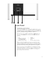
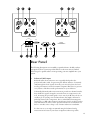
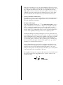
Owner’s Manual CA-2200 Power Amplifier WARNING: TO REDUCE THE RISK OF FIRE OR ELECTRIC SHOCK, DO NOT EXPOSE THIS APPLIANCE TO RAIN OR MOISTURE. CAUTION RISK OF ELECTRIC SHOCK DO NOT OPEN CAUTION: TO REDUCE THE RISK OF ELECTRICAL SHOCK, DO NOT REMOVE COVER. NO USER-SERVICEABLE PARTS INSIDE. REFER SERVICING TO QUALIFIED PERSONNEL. NOTICE All of us at Classé take extreme care to ensure that your purchase will remain a prized investment. We are proud to inform you that all Classé components have been officially approved for the European Community (CE) mark. This means that your Classé product was subjected to the most rigorous manufacturing and safety tests in the world. The CE mark certifies that your purchase meets or exceeds all European Community requirements for unit-to-unit consistency and consumer safety. This equipment has been tested and found to comply with the limits for a Class B digital device, pursuant to Part 15 of the FCC Rules. These limits are designed to provide reasonable protection against harmful interference in a residential installation. This equipment generates, uses and can radiate radio frequency energy and, if not installed and used in accordance with the instructions, may cause harmful interference to radio communications. However, there is no guarantee that interference will not occur in a particular installation. If this equipment does cause interference to radio or television reception, which can be determined by turning the equipment on and off, the user is encouraged to try to correct the interference by one or more of the following measures: • • • • Reorient or relocate the receiving antenna; Increase the separation between the equipment and the receiver; Connect the equipment into an outlet on a circuit different from that to which the receiver is connected; Consult the dealer or an experienced radio/TV technician for help. CAUTION: Changes or modifications to this equipment not expressly approved by the manufacturer could void the user’s authority to operate the equipment. This product incorporates copyright protection technology that is protected by U.S. patents ad other intellectual property rights. Use of this copyright protection technology must be authorized by Macrovision, and is intended for home and other limited viewing uses otherwise authorized by Macrovision. Reverse engineering or disassembly is prohibited. The information contained in the manual is subject to change without notice. The most current version of this manual will be posted on our web site at http://www.classeaudio.com. Marking by the “CE” symbol (shown left) indicates compliance of this device with the EMC (Electromagnetic Compatibility) and LVD (Low Voltage Directive) standards of the European Community. Classé products are designed to comply with international directives on the Restriction of Hazardous Substances (RoHS) in electrical and electronic equipment and the disposal of Waste Electrical and Electronic Equipment (WEEE). The crossed wheelie bin symbol indicates compliance and that the products must be appropriately recycled or processed in accordance with these directives. This device complies with part 15 of the FCC Rules. Operation is subject to the following two conditions: (1) This device may not cause harmful interference, and (2) This device must accept any interference received, including interference that may cause undesired operation. Please record the serial number for your new Classé component here for future reference. Serial #: ____________________________________________ 2 Important Safety Instructions 1. Read these instructions. 2. Keep these instructions. 3. Heed all warnings. 4. Follow all instructions. 5. Do not use this apparatus near water. 6. Clean only with dry cloth. 7. Do not block any ventilation openings. Install in accordance with the manufacturer’s instructions. 8. Do not install near any heat sources such as radiators, heat registers, stoves, or other apparatus (including amplifiers) that produce heat. 9. Do not defeat the safety purpose of the polarized or grounding-type plug. A polarized plug has two blades with one wider than the other. A grounding type plug has two blades and a third grounding prong. The wide blade or the third prong are provided for your safety. If the provided plug does not fit into your outlet, consult an electrician for replacement of the obsolete outlet. 10. Protect the power cord from being walked on or pinched particularly at plugs, convenience receptacles, and the point where they exit from the apparatus. 11. Only use attachments/accessories specified by the manufacturer. 12. Use only with the cart, stand, tripod, bracket, or table specified by the manufacturer, or sold with the apparatus. When a cart is used, use caution when moving the cart/apparatus combination to avoid injury from tip-over. 13. Unplug this apparatus during lightning storms or when unused for long periods of time. 14. Refer all servicing to qualified service personnel. Servicing is required when the apparatus has been damaged in any way, such as power-supply cord or plug is damaged, liquid has been spilled or objects have fallen into the apparatus, the apparatus has been exposed to rain or moisture, does not operate normally, or has been dropped. 15. Do not expose this apparatus to dripping or splashing and ensure that no objects filled with liquids, such as vases, are placed on the apparatus. 16. To completely disconnect this apparatus from the AC Mains, disconnect the power supply cord plug from the AC receptacle. 17. The mains plug of the power supply cord shall remain readily operable. 18. Do not expose batteries to excessive heat such as sunshine, fire or the like. The lightning flash with arrowhead symbol within an equilateral triangle is intended to alert the user to the presence of uninsulated “dangerous voltage “ within the product’s enclosure that may be of sufficient magnitude to constitute a risk of electric shock to persons. The exclamation point within an equilateral triangle is intended to alert the user to the presence of important operating and maintenance (servicing) instructions in the literature accompanying the product. WARNING: To reduce the risk of fire or electric shock, do not expose this apparatus to rain or moisture. 3 Contents Welcome to the Classé family ........................................................................... 5 a word about installation ............................................................................ 5 Unpacking and Placement ................................................................................ 6 unpacking your amplifier ........................................................................... 6 placement .................................................................................................. 6 ventilation .................................................................................................. 6 custom installations .................................................................................... 7 serial number ............................................................................................. 7 register your purchase! ............................................................................... 7 operating voltage ........................................................................................ 7 warm up/break-in period ............................................................................ 8 please read this manual .............................................................................. 8 Special Design Features .................................................................................... 9 highly refined circuit design… .................................................................... 9 extensive listening tests............................................................................... 9 extraordinary longevity ............................................................................. 10 robust protection ...................................................................................... 10 Front Panel...................................................................................................... 11 Rear Panel....................................................................................................... 13 Initial Setup ..................................................................................................... 17 configuring balanced/single-ended operation ........................................... 17 configuring amplifier turn-on delay/amp no ............................................. 18 CAN-Bus ...................................................................................................... 19 features ..................................................................................................... 19 hardware setup ......................................................................................... 20 using CAN-Bus ......................................................................................... 21 CAN-Bus shared features ............................................................................. 22 configuration ............................................................................................ 22 operate ..................................................................................................... 22 AC status .................................................................................................. 22 status ........................................................................................................ 22 name ........................................................................................................ 22 global brightness ...................................................................................... 23 global standby .......................................................................................... 23 CAN-Bus model specific features ................................................................. 23 PlayLink ................................................................................................... 23 amp info ................................................................................................... 24 event log .................................................................................................. 24 Care and Maintenance .................................................................................... 25 Troubleshooting .............................................................................................. 26 Specifications .................................................................................................. 28 Dimensions ..................................................................................................... 29 4 Welcome to the Classé family Congratulations on your purchase of a Classé product. It is the result of many years of continuous refinement, and we are sure that you will enjoy it for many years to come. We value our relationship with our customers. Please allow us to stay in touch with you by returning your warranty card now, before you pack up the shipping carton of your new product and forget all about it. Doing so will enable us to let you know about any possible future upgrades or updates that might become available for your Classé component. Sending in your warranty card also registers your product with us so that warranty service can be obtained easily and quickly, even if you have mislaid your original sales slip. Please, take a few minutes to fill out the warranty registration card, and drop it in the mail. You will find the warranty registration card at the end of the separate warranty policy booklet, enclosed. a word about installation Every effort has been made to make the Classé CA-2200 simple and straightforward to install and use. Still, we have no way to evaluate many other variables such as the size and shape of your room, its acoustics, and the associated equipment you have chosen to use with your amplifier. All of these factors influence the ultimate performance of your system. For this reason, we strongly encourage you to have your system installed and calibrated by your dealer, whose experience, training, and specialized equipment can make a profound difference in the final performance of the system. 5 Unpacking and Placement unpacking your amplifier Carefully unpack your power amplifier according to the supplied instructions, and remove all accessories from the carton. Please take care when lifting the amplifier, as it is quite heavy. Important! Keep all packing materials for future transport of your Classé product. Shipping your new component in anything other than its purpose-designed packing material may result in damage that is not covered by the warranty. placement There are two options when placing your power amplifier: you may place it close to the speakers, requiring longer interconnecting cables from the preamplifier; or place it close to the preamplifier, requiring longer speaker cables. Although either approach will yield excellent performance, you might consider the first option for two reasons. First, signal quality degrades more easily when transmitted as a combination of both high voltage and high current, suggesting that speaker cables should be kept as short as practical. Second, high quality amplifiers use massive power supplies which inevitably radiate some degree of magnetic fields. Ideally, one would separate these fields from sensitive source components by a reasonable distance. If it is more convenient for you to place the amplifier in an equipment rack, along with your other components, we suggest placing it at the bottom of the rack, well away from your source components and preamplifier. This location will also be more stable than placing such a heavy component near the top of a rack, which might make it top-heavy. Note that adequate clearance for the AC cord and connecting cables must be left behind the CA-2200. We suggest leaving eight inches (20 cm) of free space behind your power amplifier to allow all cables sufficient room to bend without crimping or undue strain. ventilation Your Classé power amplifier generates a certain amount of heat in the course of normal operation. Be sure to allow six inches of clearance above it and three inches to each side to allow heat dissipation through air circulation. The vents on both the bottom and the top of the CA-2200 must be kept free from any obstruction which would reduce the flow of air through the unit. Avoid placement on soft surfaces that would restrict airflow (such as plush carpeting). 6 custom installations Drawings are included in this manual to facilitate special installations and custom cabinetry (see the section Dimensions). An optional, purpose-designed rack mount kit is available for this product. Contact your Classé dealer for more information. serial number The serial number for your power amplifier is found on the rear of the unit. Please note and record this number on the page entitled Important Safety Instructions for your future reference. register your purchase! Having found the serial number, now would be a good time to fill out the registration card. Please register your purchase so we can advise you of updates and other items of interest. It will take only a minute or so. Please complete the card now, before you forget. operating voltage The CA-2200 power amplifier is set at the factory (internally) for 100V, 120V, 220V, 230V, or 240V AC mains operation, as appropriate for the country in which it is to be sold (230V only in European Union countries, in compliance with CE regulations). The voltage setting may not be changed by the user or dealer. Make sure that the label on the rear panel of your power amplifier indicates the correct AC operating voltage for your location. Attempting to operate your power amplifier at an incorrect voltage may damage the unit. Warning: The voltage setting of your power amplifier may not be changed by the user. There are no user-serviceable parts within the unit. Please refer any problems to an authorized Classé service center. If the AC mains voltage indicated on your power amplifier is incorrect, please contact your local, authorized Classé dealer or distributor. The CA-2200 can easily be powered by a normal 15-ampere AC mains line. If other devices are also powered from the same AC line, their additional power consumption should be taken into account. 7 The CA-2200 includes protection circuitry that will prevent the amplifier from operating at dangerously high or low voltages. • At startup: the AC mains voltage must be within a range of approximately -15% to +10% of its nominal value at startup, or the amplifier will not turn on. For example, a 120V unit requires the AC mains to be between approximately 95V–135V in order to turn on. • Over-voltage during operation: if the AC mains voltage surges by roughly 10% or more during operation, the amplifier will enter protection mode and shut down. The Standby LED will flash to indicate the protection mode has been engaged. • Under-voltage during operation: if the AC mains voltage sags by 15% or more, the amplifier will continue to play (since this does not present a particular danger to the amplifier), but note that it may not be able to achieve its usual standard of performance under these compromised conditions. The Standby LED will flash to indicate the condition. warm up/break-in period Your new Classé power amplifier will deliver outstanding performance immediately. However, you should expect to hear it improve somewhat as it reaches its normal operating temperatures and its various components “break-in.” It has been our experience that the greatest changes occur within the first 300 hours, as the amplifier reaches thermal equilibrium and the capacitors fully form. After this initial break-in period, the performance of your new product should remain quite consistent for years to come. The only exception to this rule is if the unit is placed in standby or unplugged for an extended period of time, allowing it to cool down. Depending on the degree of cooling involved, you should expect a brief warm-up period before the power amplifier’s sound quality is at its best. Unless your amplifier was allowed to become quite chilled, subsequent thermal re-stabilization should not take long. Fortunately, you should never have to repeat the initial 300 hour break-in period. please read this manual… Please take a few minutes to review this manual, and to familiarize yourself with your new amplifier. We understand that you are anxious to plug everything in and get started. However, reading this manual and following the advice it gives will ensure that you get all the benefits you deserve from having purchased such a fine piece of equipment. 8 Special Design Features highly refined All Classé analog amplification stages are based on circuits that have been circuit design extensively optimized over many years of continuous development. By starting with excellent circuit designs and working with them over the years, we are able to discover the many small refinements that add up to superlative performance, in a variety of applications. Altering a voltage here, or using a slightly different part there, may make all the difference between solid and absolutely outstanding performance. This level of refinement only comes with a great deal of experience, and is not available to those who flit from one trendy notion to the next. It accounts in no small measure for both the consistency of sonic performance among Classé products (as they are all based on similar analog gain stages), and for the consistently excellent reviews those products receive by owners and reviewers alike. extensive listening tests Excellent measured performance is to be expected in world-class products, and Classé products deliver that performance. However, experience has shown that technical excellence alone is insufficient to guarantee subjectively musical results. For this reason, all Classé products are laboriously fine-tuned during the development process by carefully controlled listening tests. Our ears are still some of the finest laboratory test instruments available, and nicely complement more traditional engineering test equipment. In the course of optimizing the circuitry for a product, hundreds of decisions are made based on the subjective impression given by substituting one high quality part for another. As an example, we may listen to half a dozen 0.1% film resistors of the same value, from several different companies. Standard tests may show them all to provide identical results in terms of noise, distortion, and so forth. Yet, almost invariably, one selection yields some small improvement in the subjective reaction to the performance of the product under development. Less often, even a single such change can result in a surprisingly large improvement. Multiply those various improvements by the dozens or even hundreds of such decisions that must be made before the product can be finalized for production, and you have a remarkable improvement, indeed—all based on careful listening tests, which we view as a necessary complement to the solid engineering you might rightly expect from Classé. 9 extraordinary longevity Another benefit of having worked with highly refined circuit designs so extensively over many years is that we have vast experience in what works well over the long term. By using only the highest quality parts to begin with, and then using them in an informed way as a result of both accelerated aging experiments and actual longterm experience, we are able to design and manufacture products which we are confident will stand the test of time. We are confident that your new Classé product will give you many years of trouble-free reliability and musical enjoyment, just as previous Classé products have given their owners. robust protection Finally, your new Classé amplifier incorporates a variety of protection circuits, all designed to protect both the amplifier and your loudspeakers against dangerous fault conditions. Significantly, these protection circuits do not intrude upon or limit the normal performance of the amplifier; rather, they simply put the amplifier into protection mode when confronted with abnormal conditions. These conditions include: • • • • output overload DC offset AC mains voltage (outside of normal tolerances) excessive operating temperatures If any of the first three conditions occurs on either channel (any of which might harm either your amplifier or possibly your loudspeakers), the amplifier will immediately go into protection mode. In such a case, a Channel LED indicator will blink red, indicating the channel with the fault, and the sound will be muted until the fault can be righted. If the fault is not channel-related, e.g. AC mains voltage out of range, the Standby LED will blink. In all cases, the unit will need to be re-started once the cause of the fault condition has been rectified. 10 Front Panel 1 Standby button & LED indicator The front panel Standby button will toggle the amplifier between operate, its fully operational state, and a standby mode that leaves the amplifier off, yet ready to respond to system commands via any of the supported control options (e.g. IR input, DC trigger, CAN-Bus, or RS-232). The current state of the amplifier is indicated by the LED indicator in the center of the Standby button. The state of this LED indicates the following: • • • • on flashing (on power-up) off + Channel LED on flashing (after power-up) = = = = standby initialization operate AC mains voltage out of range When in standby, the amplifier’s gain stages are powered down. Only a small power supply and control circuit remain on, consuming relatively little power. Fortunately, since the output stages by their nature conduct a great deal of current, they warm up and sound their best very quickly. If you are not going to use the amplifier for an extended period of time, perhaps while traveling for a vacation, we suggest you disconnect it from the AC mains. Please be certain that the amplifier is in standby prior to disconnecting it from the AC mains. 11 Also, it is a good practice to physically disconnect any and all valuable electronics from the AC mains during electrical storms, as a lightning strike anywhere near your home can put a tremendous surge on the AC mains that can easily damage any piece of electronics, no matter how well designed and protected. The best protection in the case of severe electrical storms is to simply remove the electronics from any connection with the power grid. 2 Select button The Select button is used (along with the Mode button) when configuring the amplifier for either balanced or single-ended operation. It is also used when configuring the turn-on delay or amplifier number for an amplifier connected to a Classé preamplifier by the DC Trigger or CAN-Bus control systems. 3 Channel status LED indicators Each amplifier channel has two Channel LED indicators. They are used to indicate the use of either balanced (XLR) or single-ended (RCA) inputs for that channel. These indicators are also used to indicate fault conditions in your amplifier, should any ever arise. If a channel’s LED indicators blink red, there is a problem in that particular channel. If all the Channel LEDs are blinking red, there may be a systemic problem that is not specific to a particular channel. Caution! If you see any Channel LED Indicator blinking red, please disconnect the amplifier from the AC mains immediately and check that all external connections are cleanly made and secure. If the AC mains are not easily accessible, you can press and hold the Standby button for three seconds to reset the amplifier. If no fault is immediately obvious, please call your authorized Classé dealer for assistance. 4 12 Mode button The Mode button is used (along with the Select button) when configuring the amplifier for either balanced or single-ended operation. It is also used when configuring the turn-on delay and amplifier number of the amplifier when it is connected to a Classé preamplifier by the CAN-Bus communications or Trigger systems. #!."53 ). /54 23 7!2.).' ). /54 ). 2%0,!#%&53%7)4( 3!-%490%!.$2!4).'/.,9 /54 Rear Panel The following descriptions are intended as a quick reference, should you have any questions about your new product. Please see the next section (entitled Initial Setup) for specific advice on incorporating your new amplifier into your system. 1 Balanced (XLR) Input Balanced audio interconnections were originally developed in the professional audio world, for preserving the delicate nuances of extremely small microphone-level signals. For many years now, they have also been used by performance-oriented consumer companies like Classé to preserve every nuance of the finest audio performances in your collection. Technically, balanced audio interconnections provide two distinct benefits: they double the signal’s strength as it travels from one component to the next, increasing the potential signal to noise ratio by 6 dB; they also do an excellent job of rejecting noise and interference that might otherwise be picked up between the components, due to either EMI (electromagnetic interference) or RFI (radio frequency interference). In the world of wireless telecommunications, there is more potential interference around than ever before—it makes sense to keep it out of music and movie soundtracks. For this reason, we strongly recommend using the balanced analog interconnections between your Classé components wherever possible. 13 The pin assignments of these XLR input connectors are: Pin 1: Signal ground Pin 2: Signal + (non-inverting) Pin 3: Signal – (inverting) Connector ground lug: chassis ground These pin assignments are consistent with the standard adopted by the Audio Engineering Society (AES14-1992). If you are using your Classé power amplifier with a Classé preamplifier, you’re all set – just take standard balanced interconnect cables and plug them in.Then engage that input on the power amplifier by configuring it as described in Initial Setup. If you are using another brand of preamplifier, please refer to the operating manual of your balanced-output preamplifier to verify that the pin assignments of its output connectors correspond to your amplifier. If not, have your dealer wire the cables so that the appropriate output pin connects to the equivalent input pin. 2 Single-Ended (RCA) Input Single-ended cables using RCA connectors are the most common form of analog connection used in consumer electronics. When implemented carefully and with use of high quality interconnecting cables, this standard can provide excellent performance. Classé has gone to extraordinary effort to ensure that the single-ended (RCA) inputs of your power amplifier are as good as possible. However, this connection standard cannot offer the immunity from interference that balanced interconnection does—hence our recommendation to use the balanced inputs when possible. If you elect to use the single-ended inputs of your Classé power amplifier, you need to engage them by configuring the amplifier as described in Initial Setup. 3 Speaker Outputs Two pairs of high quality five-way binding posts are provided on the amplifier, in order to facilitate “bi-wiring.” In practice, bi-wiring involves connecting two (preferably identical) sets of speaker cables between each amplifier channel and its corresponding loudspeaker. In many cases, the benefit is a subjectively improved level of clarity and detail from the speaker, as a result of being able to feed the two separate sections of its crossover and driver complement with identical, yet separate signals. (Many high quality loudspeakers also offer two sets of connections on their speakers. Generally, one set of the connections on the loudspeaker feeds the portion of the speaker’s crossover network that supplies the woofer with its signal; the other set of connections connects to the portion of the crossover that supplies the rest of the speaker with the midrange and high frequencies.) 14 Although the binding posts on your Classé amplifier will accept bare wire connections, we strongly recommend the use of high quality spade or hook lugs, crimped and soldered onto the ends of your speaker wires. Using high quality connectors will ensure that your speaker connections do not gradually deteriorate from fraying and oxidizing bare wires. It also helps prevent accidental short-circuits from poorly-terminated connections. 4 Classé CAN-Bus Control Ports These RJ-45 connectors are reserved for future control and communication applications using Classé Audio’s implementation of the Controller Area Network (CAN) Bus specification. 5 IR Input and Output Your Classé amplifier includes two 1/8th-inch mini mono-jacks in order to support the IR remote controls that are ubiquitous today. IR commands exist for toggling the amplifier between operate and standby, as well as discrete command codes for either operate or standby. These codes may be used in “macros” for sophisticated remote control systems, facilitating the control of the amplifier in the larger context of a complete system. Actually, this IR Input and Output description is a bit of a misnomer: the input supplied to these plugs is electrical in nature, not IR. It is obtained by using standard IR receivers, distribution amplifiers, and emitters (available from your dealer) to translate the remote’s flashes of infrared light into corresponding pulses of electricity. The big advantages here include being able to easily route the signals anywhere they might need to go, and the reliability of a solid electrical connection. Since an IR distribution system such as your dealer may design for you usually must control many products, your amplifier includes both an IR input (for the control of this product) and an IR output (so as to pass along the same signal to the next product). This allows you to “daisy chain” your control wires from one product to the next. The amplifier is designed to respond to IR commands of 5 Volts DC, with the tip of the mini mono-plugs defined to be “positive” relative to the shank of the plug. 15 6 DC Trigger Input and Output Many audio/video preamplifiers can supply a DC control voltage to associated equipment in order to induce desired behavior. Your Classé amplifier can take advantage of these capabilities in order to be switched between operate and standby automatically, perhaps in concert with the A/V preamp itself. Two 1/8th-inch mini mono-jacks provide this remote-controlled turn-on (that is, toggling between operate and standby) of the amplifier. These jacks provide a simple pass-through of the control voltage from one to the other, allowing you to “daisy-chain” a series of amplifiers quite easily. The remote trigger will be operated by the presence of 5–12 Volts DC, with tip polarity as shown below: 7 RS-232 Control Port This DB-9 connector has two purposes: • downloading new operating software into your amplifier (should new features ever be added, for example) • for external control of your amplifier by systems such as i-Command™, AMX® and Crestron™ For more information, please contact your dealer and ask about home automation systems. 8 AC Mains Input An IEC standard power cord is used with the CA-2200. Plug the cord into the IEC receptacle on the rear panel, and the other end into a suitable wall outlet. 9 AC Mains Fuse Your Classé power amplifier has an AC mains fuse, accessible on the rear panel. If you suspect that your AC fuse has blown, disconnect your amplifier from the AC mains, as well as from its input connections and speaker connections, and refer to the appropriate item of the section enitled Troubleshooting. Do not open your amplifier. There are no user-serviceable parts within this product. Danger! 16 Potentially dangerous voltages and current capabilities exist within your power amplifier, even when disconnected from AC mains. Do not attempt to open any portion of the amplifier’s cabinet. There are no user-serviceable parts inside your power amplifier. All service of this product must be referred to a qualified Classé dealer or distributor. Initial Setup Your new Classé amplifier is quite simple to set up and enjoy. Please follow the steps outlined below in order to safely set up and use your new amplifier. Important: The AC mains connection should be the last connection you make on your new power amplifier. In addition, it is always a good idea to power up your power amplifier(s) last, after everything else has been powered up and has stabilized. . Conversely, it is good practice to power the amplifier(s) down first when shutting down the system, as this prevents any transients from other components from getting through to your loudspeakers. configuring balanced/ single-ended operation 1. Unpack everything according to the included instructions. Be careful when doing so, as this amplifier is quite heavy. 2. Place your amplifier (be sure to read “Unpacking and Placement”) and connect it to the AC mains. This includes deciding on the location, making sure you have adequate ventilation, and adequate clearance for all the wires behind the amplifier. Once accomplished, connect the amplifier directly to the AC mains. Do not use extension cords, as most are not suitable for the current sometimes required by your amplifier. 3. Configure your amplifier. The Select and Mode buttons are used when configuring your amplifier for how you would like it to operate. While in standby, pressing the Select button will cause the Channel LEDs to light up, indicating how the amplifier is currently configured (either balanced or single-ended) for each channel. One of the Channel LED indicators will be blinking, indicating that you may select either balanced or single-ended operation for that channel. Press the Mode button to toggle between either the balanced mode or the singleended mode of operation, as indicated by which of the two channel LEDs for that channel is blinking. Press the Select button again to select the other channel, and press the Mode button to select the configuration for that channel. To finish, press and release the Select button until both Channel LEDs are off. Make sure you configure the amplifier to use the type of input connection you will be using. 17 configuring amplifier turn-on delay/amp no. In a system that contains multiple Classé amplifiers, you may set the number of seconds of turn-on delay for each amplifier, allowing each to turn on in the order you have specified, rather than all at once. This number also acts as an ID when using the CAN-Bus. (Having several powerful amplifiers all turning on at the same time can sometimes stress the AC mains in your home, potentially leading to nuisance tripping of circuit breakers). For example, to set the delay for two seconds (and to designate a particular amplifier as #2): • Place the amplifier in standby (Standby LED on) • Press and hold the Mode button until both Channel LEDs are lit. When released, both LEDs will blink to indicate the turn-on delay and current number of the amplifier (e.g. once to indicate a one second delay and amplifier #1). • If you want to change the current amplifier number setting, press and hold the Mode button again until both Channel LEDs are on. • While continuing to hold the Mode button, press the Select button two times (the same number as the desired delay in seconds and the amplifier number); • Release the Mode button. The amplifier will confirm your choice by blinking the Channel LEDs twice. 4. Make your preamp connections. With the amplifier in standby (or disconnected from the AC mains), and using high quality interconnecting cables, make the appropriate connections with the balanced or single-ended connectors (as configured in Step 3). Make sure all the connections are snug, even if it means gently squeezing the outer shell of the RCA with pliers and reinserting it to tighten the connection. 5. Make your speaker connections. Make the connection between the output terminals of the amplifier and your loudspeakers, using high quality speaker wires. Connect the black (–) terminals on the amplifier to the black (–) terminals on your speaker, and the red (+) terminals on the amplifier to the red (+) terminals on your speaker. 18 If bi-wiring, run a total of four conductors between each amplifier channel and its corresponding loudspeaker: two separate +/– leads, one for the bass and the other for the mids and treble. Make sure that no wires cross between the red (+) and black (–) terminals, at either end. Make sure all the connections are snug and cannot be easily wiggled free, but do not overtighten them. If you can give the speaker wires a reasonable tug without movement, they are snug. Further tightening will not make a better connection, and (taken to the extreme) may damage the connectors. 6. Double-check all your connections. We understand that this step sounds redundant, but it is worth the extra minute or two it might take just to ensure that all connections are correct and secure before plugging the power cables to the AC outlets. 7. Turn on all the other components in your system, and then turn on your amplifier. It is always good practice to turn any power amplifier on last, and to turn it off first. Doing so prevents any turn-on/turn-off transients that might originate in other components from damaging your loudspeakers. CAN-Bus Classé’s Controller Area Network, or CAN-Bus, opens the way to a new level of interaction between our Delta range of amplifiers, preamps, processors and source components. When the CA-2200 is connected with CAN-Bus, the different elements of a Delta series system are in constant communication, creating a “global” network that delivers system wide status information and shared operational features, all through the touchscreen display. features CAN-Bus will allow a single Delta series touchscreen to: • Display status information for every connected unit, including amplifiers which do not have a touchscreen display. • Create a “PlayLink” that allows an SSP or Preamp to automatically switch to the correct input when a Delta series source component starts playback. • Adjust the global system brightness. • Configure the entire system to go in and out of standby at the touch of a button and also bring individual components in and out of standby. • Mute any connected unit. 19 hardware setup 1 20 Classé Delta Series Products Two or more Classé Delta series products are required, at least one of which must have a touchscreen display. 2 Category 5 Network Cables These are ordinary network cables, commonly used for broadband Internet connections. They should be typical “straight through” cables not the “crossed over” type, and the total required will be one less than the total number of Delta series components in your system. 3 CAN-Bus Terminator A single CAN-Bus Terminator may be required. It is inserted into the CAN-Bus OUT connector of the last component in the CAN-Bus daisy chain. One is included in the box with your CA-2200. They are also available free of charge from your nearest Classé Customer Support Centre http://www.Classeaudio.com/support/service.htm 4 SSP-300 & 600 CAN-Bus Interface Box Systems that include an SSP-600 or SSP-300 will also require an SSP-300/600 CAN-Bus Interface Box. These are included with the products or available free of charge from your nearest Classé Customer Support Centre http://www.Classeaudio.com/support/service.htm The diagrams below illustrate how to connect the CAN-Bus hardware. Any combination of models in any order without SSP-300 or SSP-600. CAN-BUS IN OUT CAN-BUS IN OUT CAN-BUS IN OUT CAN-BUS IN OUT Any combination of models in any order with SSP-300 or SSP-600. CAN-BUS IN OUT CAN-BUS IN OUT CAN-BUS IN OUT CAN-BUS IN OUT NOTE: Daisy chain may need to be terminated with CAN-Bus Terminator. using CAN-Bus CAN-Bus is controlled via the touchscreen of any Delta series component. There is no master component, so Delta series systems where two or more units have a touchscreen can be controlled through any of the touchscreens. However, it is probably easiest to start using CAN-Bus through just one. CAN-Bus is accessed by pressing the menu button on the face of the unit or remote, then the status button, followed by the more button. 21 The touchscreen will then display the CAN-Bus devices screen, which lists connected Delta series components by model & serial number. Highlighting a unit on the CAN-Bus devices screen identifies it as the target unit. The front panel LEDs of the target unit will start flashing (unless you highlight the unit that you are using to access CAN-Bus). Once you have chosen the target unit press select. The target unit’s LEDs will stop flashing and the touch screen will list the CAN-Bus features available to it. Some CAN-Bus features are shared by all models, some are specific to individual models. CAN-Bus shared features configuration operate AC status 22 The following CAN-Bus features are shared by all models. Selecting configuration will present the CAN-Bus configuration screen allowing access to name, global brightness, and global standby features. The operate settings allow you to bring the target unit in and out of standby, or mute. This key will be disabled for the unit whose touchscreen you are using to access CAN-Bus. The AC status screen displays information from the target unit’s electrical supply sensors. Two screens are available, with the second accessed by selecting more. status The status screen is the simplest way to access essential information about the target unit. It displays the target unit’s model number, software version, operational status and serial number. name Allows you to set the name that this component will be listed under in the CAN-Bus devices screen. The name will appear next to the unit model and serial number, and facilitate the identification of units in large systems. global brightness By setting all your components to global brightness you can adjust the touchscreen and LED brightness for your entire system by changing the brightness of a single touchscreen. All CAN-Bus software updates automatically set the updated unit to Global Brightness. If you want a particular unit to be excluded from Global Brightness, deselect Global Brightness for that unit. global standby By setting all your components to global standby you can bring your entire system in and out of standby by pressing the standby button of any unit or remote. All CAN-Bus software updates automatically set the updated unit to global standby. If you want a particular unit to be excluded from global standby, deselect global standby for that unit. CAN-Bus model The following CAN-Bus features are model specific. specific features PlayLink This feature is exclusive to Delta series disc players and will only function if the disc player is connected to a CAN-Bus enabled preamp or surround sound processor. When PlayLink is active, pressing play on the disc player will also automatically switch the preamp/processor to a specified input. This means that you can listen to a CD or watch a DVD literally at the touch of a button. The first step in using PlayLink is to choose the input you wish to be selected when play is pressed on the disc player. Press the PlayLink icon, then select the correct input from the list. Once you have selected the input press back, then select configuration. PlayLink is activated and disabled through the PlayLink icon on the CAN-Bus configuration screen. 23 PlayLink is automatically active after a software update, and the PlayLink icon will only appear on the CAN-Bus configuration screen of a Delta series disc player. PlayLink can only select a single input per disc player. It is therefore not designed for users who regularly play both CDs and DVDs through different inputs from a single disc player. When PlayLink is active the disc player will default to the same input every time play is pressed, regardless of whether it is playing CD or DVD. amp info Available for amplifiers only, this screen displays the data provided by the heatsink and AC Module temperature sensors. NOTE: This feature is only accessible when the target amplifier is on. event log Reserved for amplifiers, this feature is a protection circuitry event log which can only be accessed when the target amplifier is in standby. The protection circuit shuts down the amplifier or channel if it overheats or if its output could damage your speakers. The event log details the circumstances surrounding the amp going into protection and should be referred to in situations that require the intervention of your dealer or Classé customer support. The log can report the following events interpreted as follows: • +ve slow blo trip & -ve slow blo trip — The average current has reached the safe operating limit. • +ve fast blo trip & -ve fast blo trip — The peak current has reached the safe operating limit. • over temperature trip — The unit temperature has reached the safe operating limit. • DC protection trip — The DC output level has reached the safe operating limit. • Communication failure — There has been a loss of communication between the amp’s system monitoring sensors. • AC line trip — The power supply has reached the limits of the amp’s safe operating range. These events are rare and generally occur due to issues that are external to the amp. They should be interpreted positively. The amp is doing what it’s designed to do. 24 Care and Maintenance To remove dust from the cabinet of your amplifier, use a feather duster or a lintfree soft cloth. To remove dirt and fingerprints, we recommend isopropyl alcohol and a soft cloth. Dampen the cloth with alcohol first and then lightly clean the surface of the amplifier with the cloth. Do not use excessive amounts of alcohol that might drip off the cloth and into the amplifier. Caution! At no time should liquid cleaners be applied directly to the amplifier, as direct application of liquids may result in damage to electronic components within the unit. 25 Troubleshooting In general, you should refer any service problems to your Classé dealer. Before contacting your dealer, however, please check to see if the problem is listed here. 1. No sound, and no Channel LED is lit. • The amplifier is not plugged into the AC mains, or the AC mains are down (circuit breaker, fuse). • A brown-out or short-term loss of power might require the internal microprocessor to be reset. Unplug the unit for at least 30 seconds and then plug it in again and try powering it up. • The AC mains fuse is blown. See Troubleshooting #4, below (or contact your Classé dealer). • The AC mains is out of range. Check the voltage specified on the rear panel. 2. No sound, and one or more Channel LEDs is blinking red. • Your protection circuitry may have been engaged. To reset the amplifier, press and hold the Standby button for 3 seconds to power down the amplifier. Then disconnect all inputs and outputs. • Then try powering up the amplifier by pressing the Standby button. If the LED continues to blink, there is a fault condition in the amplifier itself. It should be powered down, disconnected from the AC mains and taken to your Classe dealer for service. • If it powers up without any difficulty, power it back down and reconnect only the inputs. Then restart the amplifier. If it goes into its blinking protection mode, something is wrong with a component “upstream” of the amplifier—probably a DC offset or similar problem. Your amplifier is trying to protect your loudspeakers (even small amounts of DC can damage woofers in relatively little time). Try different source components to discover whether the problem is limited to a single source, or exists all the time (which would indicate a problem with the preamplifier). Contact your dealer for help with the appropriate component. 3. The amplifier keeps shutting off. • Make sure you are providing adequate ventilation to the amplifier, and that the ambient room temperature is below 105°F (40°C). • Run through the troubleshooting sequence outlined above (assuming the amplifier is going into its protection mode). 4. The AC mains fuse is blown. There is a specific troubleshooting procedure for a blown AC mains fuse, since this rare occurrence sometimes indicates a significant problem. Please follow the following steps, in order: a. Disconnect your amplifier from the AC mains, as well as from its input connections and speaker connections, and remove the fuse cover on the rear of the unit. 26 b. If the fuse appears to be blown, replace it only with a fuse of the same type and rating (specified below). Using any other type of fuse, particularly a larger-value fuse, can result in permanent damage to your amplifier. If you are uncomfortable replacing the fuse yourself, contact your Classé dealer for assistance. Mains voltage: Fuse type: Rating: 100/120VAC MDA slow-blow 10A Mains voltage: Fuse type: Rating: 230/240VAC MDL slow-blow 8A c. After replacing the fuse and fuse cover, reconnect the amplifier to the AC mains only and turn it on without reconnecting either the inputs or the speaker wires. If the fuse blows again, disconnect it from the AC mains and contact your Classé dealer for assistance. d. If everything seems fine, place the amplifier back into standby and carefully reconnect the input cable and power the amplifier up. If the fuse then blows (or the amplifier goes into protection), you may have a serious fault with your preamplifier/processor. Contact your Classé dealer. e. Finally, if everything is still fine, place the amplifier in standby and carefully reconnect the speaker wires. Check both ends of the speaker wires for possible short circuits. Then power up the amplifier again. If the amplifier remains functional (the fuse does not blow), then the original fuse probably blew in order to protect the amplifier from a large AC mains surge. If it blows again, contact your Classé dealer for assistance. 5. The Standby LED is flashing quickly, and a Channel LED is flashing red. • Try resetting the unit by disconnecting it from the AC mains power, waiting a few seconds, and reconnecting the amplifier to power. If this does not solve the problem, contact your Classé dealer for assistance. 27 Specifications All specifications are accurate at the time of printing. Classé reserves the right to adjust specifications without notice. Power output (both channels driven) Frequency response 200W/ch continuous rms @ 8Ω 400W/ch continuous rms @ 4Ω 10Hz – 22kHz (+0/-0.1dB) 10Hz – 155kHz (+0/-3.0dB) Phase better than -10° @ 22kHz Signal-to-noise ratio 108dB (ref. full ouput, 10Hz – 80kHz) Channel separation better than 110dB @ 20kHz Noise floor (FFT) all peaks less than -95dBV (10Hz – 80kHz) Distortion (THD + noise) 0.003% @ 8Ω (unweighted, 1.0Vrms/1kHz input, 10Hz – 500kHz) Voltage gain 29.1dB Sensitivity 1.4Vrms for rated output @ 8Ω Input Impedance 100kΩ Rated power consumption (as per IEC60065 para. 2.3.10) 480W Idle power consumption 166W Mains voltage specified on rear panel (cannot be changed by dealer or user). Dimensions (not incl. controls or connectors) Width: 17.5” (445mm) Height: 8.75” (222mm) Depth: 18.5” (470mm) Shipping weight 92lbs (42kg) Net weight 80lbs (36kg) For more information, see your Classé dealer, or contact: Classé Audio 5070 François Cusson Lachine, Quebec Canada H8T 1B3 Telephone +1 (514) 636-6384 FAX +1 (514) 636-1428 Internet: http://www.classeaudio.com email: [email protected] Classé and the Classé logo are trademarks of Classé Audio Inc. of Lachine, Canada. All rights reserved. i-Command™ is a trademark of Equity International, Inc. All rights reserved. AMX® is a registered trademark of AMX Corporation of Richardson, TX. All rights reserved. 28 Crestron™ is a trademark of Crestron Electronics, Inc. of Rockleigh, NJ. All rights reserved. Dimensions 29 Classé Audio 5070 François Cusson Lachine, Quebec Canada H8T 1B3 +1 (514) 636-6384 +1 (514) 636-1428 (fax) http://www.classeaudio.com email: [email protected] North America: 1 800 370 3740 email: [email protected] Europe: 44 (0) 1903 221 700 email: [email protected] Asia: (852) 2790 8903 email: [email protected] All Others: +1 514 636 6394 email: [email protected] Copyright © 2007 Classé Audio, Inc. Printed in Canada. V 2.4 100107