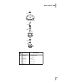
1
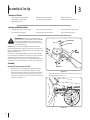
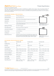
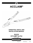
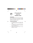
To The Owner • Assembly & Set-Up • Controls • Operation • Maintenance • Parts List
Operator’s Manual
Two-Stage Snow Thrower Attachment — 19A-126-100
WARNING
READ AND FOLLOW ALL SAFETY RULES AND INSTRUCTIONS IN THIS MANUAL
BEFORE ATTEMPTING TO OPERATE THIS MACHINE.
FAILURE TO COMPLY WITH THESE INSTRUCTIONS MAY RESULT IN PERSONAL INJURY.
CUB CADET LLC, P.O. BOX 361131 CLEVELAND, OHIO 44136-0019
Printed In USA
Form No. 769-03385A
(August 05, 2009)
1
To The Owner
Thank You
Thank you for purchasing a snow thrower attachment
manufactured by Cub Cadet LLC. It was carefully engineered
to provide excellent performance when properly operated and
maintained.
Please read this entire manual prior to operating the equipment.
It instructs you how to safely and easily set up, operate and
maintain your machine. Please be sure that you, and any other
persons who will operate the machine, carefully follow the
recommended safety practices at all times. Failure to do so could
result in personal injury or property damage.
This product has met the rigid safety standards of the Outdoor
Power Equipment Institute and an independent testing
laboratory. If you have any problems or questions concerning
this attachment, phone your local Cub Cadet dealer. Cub Cadet’s
Customer Support telephone numbers, website address and
mailing address can be found on this page. We want to ensure
your complete satisfaction at all times.
Throughout this manual, all references to right and left side of the
machine are observed from the operating position.
All information in this manual is relative to the most recent
product information available at the time of printing. Review
this manual frequently to familiarize yourself with the machine,
its features and operation. Cub Cadet LLC reserves the right to
change product specifications, designs and equipment without
notice and without incurring obligation.
Table of Contents
Safe Operation Practices......................................... 2 Operation.................................................................10
Assembly & Set-Up................................................... 3 Maintenance............................................................11
Controls..................................................................... 8 Illustrated Parts List................................................14
Record Product Information
Before setting up and operating your new equipment, please
locate the model plate on the equipment and record the
information in the provided area to the right. You can locate the
model plate by standing at the operator’s position and looking
down at the rear of the auger housing. This information will be
necessary, should you seek technical support via our web site or
with your local Cub Cadet dealer.
Model Number
Serial Number
Customer Support
If you have difficulty assembling this product or have any questions regarding the controls, operation, or maintenance of
this machine, you can seek help from the experts. Choose from the options below:
2
◊
Visit us on the web at www.cubcadet.com
◊
Locate your nearest Cub Cadet Dealer at (877) 282-8684
◊
Write us at Cub Cadet LLC • P.O. Box 361131 • Cleveland, OH • 44136-0019
Important Safe Operation Practices
2
WARNING! This symbol points out important safety instructions which, if not followed,
could endanger the personal safety and/or property of yourself and others. Read and follow
all instructions in this manual before attempting to operate this machine. Failure to comply
with these instructions may result in personal injury.
When you see this symbol. HEED ITS WARNING!
California Proposition 65
WARNING! Engine Exhaust, some of its constituents, and certain vehicle components
contain or emit chemicals known to State of California to cause cancer and birth defects
or other reproductive harm.
DANGER: This machine was built to be operated according to the safe operation practices in
this manual. As with any type of power equipment, carelessness or error on the part of the
operator can result in serious injury. This machine is capable of amputating fingers, hands,
toes and feet and throwing foreign objects. Failure to observe the following safety
instructions could result in serious injury or death.
Training
Preparation
1.
Read, understand, and follow all instructions on the
machine and in the manual(s) before attempting to
assemble and operate. Keep this manual in a safe place for
future and regular reference and for ordering replacement
parts.
1.
Thoroughly inspect the area where the equipment is to be
used. Remove all door mats, newspapers, sleds, boards, wires
and other foreign objects which could be thrown by the
auger/impeller.
2.
Be familiar with all controls and their proper operation.
Know how to stop the machine and disengage them
quickly.
2.
Always wear safety glasses or eye shields during operation and
while performing an adjustment or repair to protect your eyes.
Thrown objects which ricochet can cause serious injury to the
eyes.
3.
Never allow children under 14 years old to operate this
machine. Children 14 years old and over should read and
understand the operation instructions and safety rules in
this manual and should be trained and supervised by a
parent.
3.
Do not operate without wearing adequate winter outer
garments. Do not wear jewelry, long scarves or other loose
clothing which could become entangled in moving parts. Wear
footwear which will improve footing on slippery surfaces.
4.
Never allow adults to operate this machine without proper
instruction.
4.
Adjust collector housing height to clear gravel or crushed rock
surfaces.
5.
Thrown objects can cause serious personal injury. Plan
your snow throwing pattern to avoid discharge of material
toward roads, bystanders and the like.
5.
Disengage all clutches and shift into neutral before starting the
engine.
6.
Never attempt to make any adjustments while engine is
running, except where specifically recommended in the
operator’s manual(s).
7.
Let tractor engine and attachment adjust to outdoor
temperature before starting to clear snow.
6.
7.
Keep bystanders, pets and children at least 75 feet from the
machine while it is in operation. Stop machine if anyone
enters the area.
Exercise caution while operating tractor with this
attachment, especially when traveling in reverse.
3
8.
4.
Do not operate machine while under the influence of
alcohol or drugs.
5.
Muffler and engine become hot and can cause a burn. Do
not touch.
6.
Exercise extreme caution when operating on or crossing
gravel surfaces. Stay alert for hidden hazards or traffic. Do
not carry passengers.
7.
Exercise caution when changing direction and while
operating on slopes.
8.
Do not clear snow across the face of slopes; go up and
down. Exercise extreme caution when operating on slopes.
Do not attempt to clear steep slopes.
9.
Keep the nozzle in contact with the rim of the fuel
tank or container opening at all times, until refueling is
complete. Do not use a nozzle lock-open device.
Plan your snow throwing pattern to avoid discharge
towards windows, walls, cars etc. To avoid property
damage or personal injury caused by a ricochet.
10.
e.
Extinguish all cigarettes, cigars, pipes and other sources
of ignition.
Never direct discharge at children, bystanders and pets or
allow anyone in front of the machine.
11.
f.
Never fuel machine indoors.
Do not overload machine capacity by attempting to clear
snow at too fast of a rate.
g.
Never remove gas cap or add fuel while the engine is hot
or running.
12.
Never operate this machine without good visibility or light.
13.
h.
Allow engine to cool at least two minutes before
refueling.
Disengage power to the auger/impeller when transporting
or not in use.
14.
i.
Never over fill fuel tank. Fill tank to no more than ½ inch
below bottom of filler neck to provide space for fuel
expansion.
Never operate machine at high transport speeds on
slippery surfaces. Look down and behind and use care
when in reverse.
15.
If the machine should start to vibrate abnormally, stop
the engine, disengage the power take-off, lower the
attachment and set the parking brake. Inspect thoroughly
for damage. Repair any damage before starting and
operating.
16.
After striking a foreign object, stop the engine (motor),
remove the wire from the spark plug, thoroughly inspect
the snow thrower for any damage, and repair the damage
before restarting and operating the snow thrower.
17.
Disengage the power take-off, lower attachment, set
the parking brake and stop engine before you leave the
operating position. Wait until the auger/impeller comes to
a complete stop before unclogging the discharge chute,
making any adjustments, or inspections.
18.
Do not carry passengers.
To avoid personal injury or property damage use extreme care
in handling gasoline. Gasoline is extremely flammable and the
vapors are explosive. Serious personal injury can occur when
gasoline is spilled on yourself or your clothes which can ignite.
Wash your skin and change clothes immediately.
a.
Use only an approved gasoline container.
b.
Never fill containers inside a vehicle or on a truck or
trailer bed with a plastic liner. Always place containers on
the ground, away from your vehicle, before filling.
c.
d.
When practical, remove gas-powered equipment from
the truck or trailer and refuel it on the ground. If this is
not possible, then refuel such equipment on a trailer
with a portable container, rather than from a gasoline
dispenser nozzle.
j.
Replace gasoline cap and tighten securely.
k.
If gasoline is spilled, wipe it off the engine and
equipment. Move machine to another area. Wait 5
minutes before starting the engine.
l.
Never store the machine or fuel container inside where
there is an open flame, spark or pilot light (e.g. furnace,
water heater, space heater, clothes dryer etc.).
m. Allow machine to cool at least 5 minutes before storing.
Operation
1.
4
Do not put hands or feet near rotating parts, in the auger/
impeller housing or discharge chute. Contact with the
rotating parts can amputate hands and feet.
2.
Never operate with a missing or damaged discharge chute.
Keep all safety devices in place and working.
19.
Use only attachments and accessories approved by the
manufacturer (e.g. wheel weights, tire chains, cabs etc.).
3.
When cleaning, repairing or inspecting the snow thrower,
make certain the collector/impeller and all moving
parts have stopped. Disconnect the spark plug wire and
keep the wire away from the plug to prevent someone
from accidentally starting the machine. Do not run the
engine indoors, except when starting the engine and for
transporting the snow thrower in or out of the building.
Open the outside doors; exhaust fumes are dangerous.
20.
If situations occur which are not covered in this manual,
use care and good judgment. Contact your dealer or
telephone 1-800-800-7310 for assistance and the name of
your nearest servicing dealer.
Section 2 — Important Safe Operation Practices
Clearing A Clogged Discharge Chute
Maintenance And Storage
Hand contact with the rotating impeller inside the discharge
chute is the most common cause of injury associated with snow
throwers. Never use your hand to clean out the discharge chute.
1.
Never tamper with safety devices. Check their proper
operation regularly.
2.
Disengage power take-off, lower the attachment, set the
parking brake, stop engine and remove key to prevent
unintended starting. Wait until the auger/impeller comes to a
complete stop before cleaning, repairing, or inspecting.
3.
Check bolts, and screws for proper tightness at frequent
intervals to keep the machine in safe working condition. Also,
visually inspect machine for any damage.
4.
Do not change the engine governor setting or over-speed the
engine. The governor controls the maximum safe operating
speed of the engine.
5.
Snow thrower shave plates and skid shoes are subject to
wear and damage. For your safety protection, frequently
check all components and replace with original equipment
manufacturer’s (O.E.M.) parts only. “Use of parts which do
not meet the original equipment specifications may lead to
improper performance and compromise safety!”
6.
Check clutch controls periodically to verify they engage and
disengage properly and adjust, if necessary. Refer to the PTO
and safety interlock system in your tractor’s operator’s manual
for instructions.
7.
Maintain or replace safety and instruction labels, as necessary.
8.
Observe proper disposal laws and regulations for gas, oil, etc.
to protect the environment.
9.
Prior to storing, run machine a few minutes to clear snow from
machine and prevent freeze up of auger/impeller.
10.
Never store the machine or fuel container inside where there
is an open flame, spark or pilot light such as a water heater,
furnace ,clothes dryer etc.
11.
Always refer to the operator’s manual for proper instructions
on off-season storage.
To clear the chute:
1.
SHUT THE ENGINE OFF!
2.
Wait 10 seconds to be sure the impeller blades have
stopped rotating.
3.
Always use a clean-out tool, not your hands.
warning! Your Responsibility—Restrict the use of this power machine to persons who read, understand and
follow the warnings and instructions in this manual and on the machine.
SAVE THESE INSTRUCTIONS!
Section 2 — Important Safe Operation Practices
5
3
Assembly & Set-Up
Contents of Carton
•
One Auger Housing Assembly
•
One Upper Chute Crank Rod
•
Operator’s Manual
•
One Lift Handle Assembly
•
Two steering Linkage Covers
•
Two Self-adhesive Reflectors
•
One Hardware Pack
Contents of Hardware Pack
•
Two Quick Release Pins (714-04061)
•
Extension Spring (732-04237)
•
Two Shoulder Bolts (738-0143)
•
Five Cable Ties (725-0157)
•
Extension Spring (932-0594A)
•
Two Lock Nuts (912-3000)
WARNING! Before installing attachment, place
tractor on a firm and level surface. Place the PTO in
the disengaged (OFF) position, set the parking
brake, shut engine off and remove key to prevent
unintended starting.
HairPin Clip
Pin
Hex Nut
NOTE: References to LEFT and RIGHT indicate the left and
right sides of the tractor when facing forward in the operator’s
position. Reference to the FRONT indicates the grille end; to the
REAR the drawbar end.
Your tractor’s cutting deck, PTO belt and front deck stabilizer
bracket must be removed prior to mounting the snow thrower
attachment. Refer to your tractor’s Operator’s Manual for
detailed instructions. If your tractor is equipped with any frontend accessory (i.e. front bumper kit), it must also be removed.
Assembly
Mounting The Undercarriage Assembly
1.
Remove and retain the four hairpin clips from the pins
found on the top side of the undercarriage assembly.
Remove and retain the two rear pins and hex nuts found
on the undercarriage assembly. Remove and retain the
two clevis pins with hairpin clips. This hardware is for later
installation. See Fig. 3–1.
Clevis Pin
2.
Figure 3-1
Fasten the two pins and hex nuts, removed in step 1, to the
frame of the rider. See Fig. 3-2
Figure 3-2
6
IMPORTANT: Use a second person to assist you or a hydraulic
floor lift to complete steps 3 through 6.
3.
Place the undercarriage assembly beneath the tractor and
lift it up against the frame of the tractor. See Fig. 3-3.
Attaching Chute Directional Control
1.
Attach the chute directional control assembly to the upper
lift link on the left side of the auger housing. Assemble with
two hex screws and two saddle washers as illustrated in
Fig. 3-5. Secure with two flange nuts.
Chute Directional
Control Assembly
Upper Lift Link
Figure 3-3
4.
The weld pins on the top of the undercarriage assembly
should go through the aligning holes found along the
tractor’s frame. See Fig. 3-4.
Figure 3-5
2.
Secure the upper chute crank rod (A) to the joint block on
the lower chute crank rod with the cotter pin (B) provided.
See Fig. 3-6.
A
B
Figure 3-4
5.
6.
Fasten the undercarriage assembly to the frame with the
hairpin clips removed in step 1. See Fig. 3-4. The hairpin
clips will be inserted on the top in the front holes and in the
bottom on the rear holes as seen in the inset below.
Figure 3-6
3.
Fasten chute tilt cables to chute directional control with
two of the cable ties provided. Pull cable ties until snug and
trim excess.
Route the upper drive belt around the engine pulley.
See Fig. 3-4.
Section 3 — Assembly & Set-Up
7
Attaching The Lift Handle
1.
3.
Disengage the brake and release the hydrostatic bypass
rods (see your tractor’s owner’s manual for location of
bypass rods) and carefully move the tractor forward (by
pushing, NOT driving it) so that support tubes found on
the rear of the auger housing assembly are positioned
between the tractor’s front tires. Set the parking brake.
4.
With the help of an assistant, lift up the auger housing and
move it so that it rests over the shoulder bolts found on
tractor See Fig. 3-9.
Attach lift handle to lift bracket on the right side of auger
housing assembly with two hex screws and two flange nuts
provided. See Fig. 3-7.
Lift Handle
Shoulder Bolt
Lift Bracket
Figure 3-7
2.
Fasten the lift cable to the lift handle with two of the cable
ties provided. Pull the cable ties until snug and trim excess
Mounting Auger Assembly
NOTE: It will be necessary to have a second person assist you to
complete the following steps.
1.
Remove the steering mechanism cover by removing
the three screws which secure it. See Fig. 3-8. Retain the
hardware for later use during this installation.
Figure 3-9
Note: On some units it may be necessary to install the shoulder
bolts onto the tractor. Simply install the bolts as shown in Fig.
3-9 and secure with a flange lock nut. Both hardware parts are
included in your hardware pack.
5.
Maneuver the auger housing until the mounting holes line
up. Insert the two quick release pins from your hardware
pack on both sides. See Fig. 3-10.
Steering Mechanism Cover
Figure 3-8
2.
8
Position the auger housing assembly in front of the tractor
as seen in Fig. 3-8. Lay the belt and support tubes on the
installation surface.
Section 3— Assembly & Set-Up
Quick Release Pin
Figure 3-10
Attaching Support Tubes
Install Steering Covers
1.
1.
Secure the left support tube to the front of the
undercarriage assembly with the clevis pin and hairpin clip
removed earlier. See Fig. 3-11.
Install the two new steering mechanism covers as seen in
Fig. 3-12 using the 3 screws removed earlier.
Figure 3-12
Figure 3-11
Note: To help in lining up the support tube with the
mounting hole it may be necessary to push up and down
on the auger lift handle slightly.
2. Repeat the previous step on the right side.
Routing the Lower Drive Belt
1.
Route the lower drive belt around the lower pulley on
the spindle assembly, both pulleys on the double-idler
bracket found beneath the undercarriage, and the drive
pulley found on the rear of the snow thrower housing as
illustrated in Fig. 3-13.
2.
Attach tension spring (found on undercarriage double-idler
bracket) to the hex screw if it is not already attached.
Left Side
Spindle Pulley
View from top
Undercarriage
Double-Idler Pulleys
Tension Spring
Snow Thrower Drive Pulley
Front
Figure 3-13
Section 3 — Assembly & Set-Up
9
Set-Up
Lift Adjustment
WARNING! Never attempt to make any
adjustments while the engine is running, except
where specified in the Operator’s Manual. Place
tractor on a firm and level surface. Place the PTO in
the disengaged (OFF) position, set the parking
brake, shut engine off, and remove key to prevent
unintended starting.
Shear Pins
A pair of replacement auger shear pins and bow tie cotter pins
are included with your snow thrower. Store them in a safe place
until needed.
Skid Shoes
The snow thrower skid shoes are adjusted upward at the factory
for shipping purposes. Adjust them downward, if desired, prior
to operating the snow thrower.
Caution: It is not recommended that you operate
this snow thrower on gravel as it can easily pick up
and throw loose gravel, causing personal injury or
damage to the snow thrower and surrounding
property.
•
For close snow removal on a smooth surface, raise skid
shoes higher on the auger housing.
•
Use a middle or lower position when the area to be cleared
is uneven, such as a gravel driveway
If the lift index rod, as seen in Fig. 3-15, doesn’t latch securely or
the pivot release has too much slack in it, an adjustment can be
made as follows:
Lift Cable
Hex Nuts
NOTE: If you choose to operate the snow thrower on a gravel
surface, keep the skid shoes in position for maximum clearance
between the ground and the shave plate.
To adjust the skid shoes:
1.
Loosen the four hex nuts (two on each side) and carriage
bolts. Move skid shoes to desired position. See Fig. 3-14.
Lift Index Rod
Figure 3-15
Figure 3-14
10
2.
Make certain the entire bottom surface of skid shoe is
against the ground to avoid uneven wear on the skid shoes.
3.
Retighten nuts and bolts securely.
Section 3— Assembly & Set-Up
1.
Loosen the upper hex nut a few turns, then tighten the
lower hex nut to shorten the cable length. See Fig. 3-15.
2.
Loosen the lower hex nut a few turns, then tighten the
upper hex nut to lengthen the cable. See Fig. 3-15.
Lower Chute Crank Support Bracket Adjustment
If the spiral at the base of the lower chute crank isn’t fully
engaging with the notches in the lower chute assembly, the
support bracket can be adjusted inward or outward as follows:
1.
Loosen, but do NOT remove the two hex nuts which secure
the support bracket to the snow thrower housing. See Fig.
3-16.
Spiral
Hex Nuts
Support
Bracket
Figure 3-16
2.
Adjust the support bracket inward or outward so that the
spiral is fully engaged in the notches on the chute before
retightening the hex nuts.
Section 3 — Assembly & Set-Up
11
4
Controls
Trigger Control
Chute Directional Control
Lift Handle
Figure 4-1
Chute Directional Control (See Fig. 4-1)
Controls
WARNING! Be familiar with all controls and their
proper operation. Know how to stop the machine
and disengage them quickly.
Lift Handle (See Fig. 4-1)
The lift handle is located on the right side of the tractor and is
used to raise and lower the snow thrower attachment.
12
1.
To raise the snow thrower attachment off of the ground,
pull rearward and down on the lift handle until you feel
the lift latch on the right side of the snow thrower engage,
locking the snow thrower in a raised position.
2.
To lower the snow thrower, push downward on the lift
handle until there is enough slack in the lift cable so that
you may squeeze the trigger control. With the trigger
control squeezed, gently allow the snow thrower to lower
until it reaches the ground.
The chute directional control assembly is found on the left side
of the tractor and includes both the chute tilt lever as well as the
chute crank. Both affect the direction that the discharged snow
is thrown.
To pivot the upper section of the discharge chute, affecting the
distance and angle which the snow is thrown, move the chute tilt
lever forward or rearward into a desired position.
The direction which snow is thrown can be changed by rotating
the discharge chute with the chute crank. Turn the chute crank
clockwise to rotate the chute and discharge snow to the left.
Crank it counterclockwise to rotate the chute and discharge
snow to the right.
5
Operation
Operation
14.
WARNING! Read, understand, and follow all
instructions and warnings on the tractor, the
attachment, and in the operator’s manuals before
operating. Your snow thrower attachment is capable
of displacing snow and clearing a path a width of 42
inches.
Observe the following operating instructions for efficient snow
removal:
1.
Become familiar with and comfortable using all of your
tractor’s controls as instructed in your tractor’s Operator’s
Manual before operating it with the snow thrower
attachment.
2.
Make certain the correct weight (and volume) of motor
oil in is your tractor’s engine as instructed in the engine
Owners Guide packed with the tractor’s Operator Manual.
If the augers become jammed with a chunk of ice or a
foreign object, move the PTO into the disengaged (OFF)
position immediately and turn off the tractor’s engine
and remove the ignition key. Examine the auger area
thoroughly for damage and do NOT operate the snow
thrower attachment until any damage is repaired.
IMPORTANT: The augers are secured to the spiral shaft with
two shear pins and hex lock nuts. If you hit a hard foreign object
or an ice jam, the snow thrower is designed so that the pins
may shear. Two replacement shear pins and hex lock nuts are
provided for your convenience. Store in a safe place until needed.
NEVER replace the auger shear pins with standard hex bolts. Any
damage to the auger gearbox or other components as a result of
doing so will NOT be covered by your snow thrower’s warranty.
15.
Whenever possible, discharge snow downwind.
16.
Do NOT attempt to remove ice or hard-packed frozen snow.
17.
When the tractor (with the snow thrower attachment mounted)
is not in service, use the lift lever to lower the auger
housing assembly to the ground to relieve strain on the
tractor’s front end between uses.
3.
Always operate the snow thrower with the tractor’s engine
at maximum RPM (full throttle).
4.
NEVER override any safety features on either your tractor or
the snow thrower attachment.
18.
5.
Make certain that all nuts, bolts, and hardware are fastened
securely and tight on both the tractor and the snow
thrower attachment prior to use.
Always use tire chains and rear wheel weights on your tractor
where extra traction is needed. Refer to the table to the
right to determine which kits will fit your tractor.
19.
6.
Make certain the snow thrower attachment is assembled
properly and mounted to the tractor as instructed in this
manual.
Use drift cutters to aid in displacing snow through deep, drifted
areas.
7.
8.
Test all the controls (tractor PTO, snow thrower lift handle,
chute tilt lever & chute crank) for smooth operation prior to
operating the snow thrower.
Make all adjustments (i.e. skid shoes, lift latch) before
operating your snow thrower attachment. Follow the
instructions in the Assembly and Setup section of this
manual when doing so.
9.
Engage the tractor’s PTO to activate power to the augers
and impeller BEFORE driving the tractor forward and into
snow.
10.
Keep your tractor’s ground-speed slow. The slower your
tractor is traveling, the more effectively the snow thrower
attachment can displace snow.
11.
Adjust ground speed for snow conditions and become
familiar with different snow applications. Your snow
thrower attachment will operate differently in wet heavy
snow than it will in light, fluffy snow.
12.
Overlap a previously cleared path when necessary (deep
snow) so as not to overload the auger housing with snow.
13.
NEVER drive the tractor into a snow bank. The snow
thrower attachment is not a dozer plow. The lift linkage
and/or the snow thrower drive system can be damaged as
a result of “plowing” with the snow thrower attachment.
Engaging the Augers and Impeller
Power to the snow thrower attachment is activated by engaging
the tractor’s PTO.
1.
Place the tractor’s throttle control in the FAST (rabbit)
position and allow it to remain there for efficient snow
removal.
2.
Move the PTO knob into the “ON” position to engage the
augers and impeller.
3.
Move the PTO knob into the “OFF” position to disengage
the augers and impeller.
NOTE: The PTO knob cannot be in the engaged (ON)
position when the tractor is driving in the reverse direction.
The PTO knob must be in the disengaged (OFF) position
when the shift lever is placed in REVERSE or the electric
PTO clutch will automatically shut off. Refer to your
tractor’s Operator’s Manual for more information regarding
your tractor’s PTO and safety interlock system.
13
Replacing Shear Pins
Tire Chain Kit
The augers are secured to the spiral shaft with two shear pins
and cotter pins. If the auger should strike a foreign object or ice
jam, the snow thrower is designed so that the pins may shear. If
the augers will not turn, check to see if the pins have sheared.
See Fig. 5-1.
•
20” x 8.0” tires
OEM-190-658
Weight Kits
•
Wheel Weight Kit
OEM-190-215
•
Suitcase Weight Kit
19A-127-100
Drift Cutter Kit
•
Drift Cutter
OEM-390-679
NOTE: None of the kits in the table are included as standard
equipment with snow thrower attachment 19A-126-100. Contact
your local Cub Cadet dealer as instructed on page 2 of this
manual for availability and information regarding these kits.
Figure 5-1
caution: NEVER replace the auger shear pins with
anything other than OEM Part No.738-04124A
replacement shear pins. Any damage to the auger
gearbox or other components as a result of failing to
do so will NOT be covered by your snow thrower’s
warranty.
warning! Always turn off the snow thrower’s
engine and remove the key prior to replacing shear
pins.
14
Section 5— Operation
6
Maintenance
WARNING: Before lubricating, repairing, or
inspecting, place tractor on a firm and level surface.
Place the PTO in the disengaged (OFF) position, set
the parking brake, shut engine off, and remove key
to prevent unintended starting.
Lubrication of Chute Directional Control
The spiral on the end of the lower chute crank, the base of the
discharge chute itself and the joint blocks which connect the
lower and upper chute cranks should be lubed with multipurpose automotive grease once a season. See Fig. 6-1.
Auger Shaft
At least once a season, remove the shear bolts on the auger
shaft. Oil or spray lubricant inside and on the plastic bearings on
the shaft and near the holes where the shear bolts were removed
before reattaching them. See Fig. 6-2.
Shear Pin
Spacers
Bearing
Lube Spiral
and Chute Base
Figure 6-2
Joint Block
Figure 6-1
15
Model 19A-126-100
52
56
61
58 47
55
15
46
52
63
3
59
42
54
50
60
45 53
49 51
43
59
62
44
48
16
52
57
8
A
9
51
2
16
8
63
20
15
19
16
14
6
6
7
41
23 40
6
35
30
25
27
33
24
21
64
1
36
31
40
29
26
28
37
34
A
7
63
4
18
12
5
11
18
13
16
32 38
39
18
5
10
5
21
17 22
63
Model 19A-126-100
Ref
No.
Part Number
1
918-04315
Description
Auger Gear Box (Incl. Ref. 23-41)
Ref
No.
Part Number
33
721-0325
Description
Grease Plug
2
684-0158-0637
Impeller Assembly, 12”
34
721-0327
Grease Seal
3
684-0148-0637
Housing Assembly
35
936-0351
Flat Washer, .76 x 1.5 x .030
4
703-2734-0637
Housing Brace Bracket
36
936-0369
Flat Washer, .508 x 1.0 x .020
5
684-04163-0637
LH Spiral Auger
37
736-0617
Thrust Washer, .75 x 1.25 x .0615
6
684-04164-0637
RH Spiral Auger
38
IH-324105-R92
Thrust Bearing, .75 x 1.25 x .078
7
710-0759
Hex Cap Screw, 5/16-18 x .625
39
948-0108
Flange Bearing, .503 x .75
8
710-0260A
Carriage Bolt, 5/16-18 x .62
40
741-0700
Flange Bearing, .75 x 1.0 x .59
9
710-0276
Splined Carriage Screw
41
921-0179
Grease Seal
10
710-04484
Self Tapping Screw
42
684-0061A
Chute Crank Assembly
11
714-04040
Bow-Tie Cotter Pin
43
703-2735A-0637
Chute Crank Bracket
705-5226-0637
Chute Reinforcer
710-0276
Splined Carriage Screw
12
731-1086A
Sleeve .758 x 1.00 x 2.70
44
13
738-04124A
Shear Pin, .25 x 1.50
45
14
915-0114
Spirol Pin, 1/4 x 1-1/2
46
710-0262
Carriage Bolt, 5/16-18 x 1.5
710-04071
Carriage Screw, 5/16-18 x 1.0
15
936-0231
Flat Washer, .344 x 1.125 x .12
47
16
736-0242
Bell Washer, .340 x .872
48
710-0703
Screw, 1/4-20 x .75
17
941-0245
Hex Flange Bearing, .75 ID
49
710-0896
Hex Index Washer Screw
18
741-0493A
Flange Bushing, .80 x .91
50
710-0597
Hex Cap Screw, 1/4-20 x 1.00
19
784-0396B-0637
Skid Plate Bracket, 42”
51
712-04064
Nylon Hex Lock Nut, 1/4-20
20
784-5038B-0637
Slide Shoe
52
712-04063
Nylon Hex Lock Nut, 5/16-18
21
711-0469
Spacer, .75 x .125 x .5
53
715-04095
Spirol Pin, .156 x .875
22
784-5618A-0637
Hex Bearing Housing, 1.0
54
731-0851A
Chute Flange Keeper
23
918-0123A
RH Reducer Housing
55
731-1300E
Lower Chute
24
918-0124A
LH Reducer Housing
56
731-04427A
Upper Chute
25
703-2733A-0637
Housing Brace Plate
57
731-1379D
Adapter Chute
26
710-0642
Self Tapping Screw, 1/4-20 x .75
58
731-1313C
Chute Tilt Cable Guide
27
711-04468
Spiral Axle, 41.5”
59
941-0475
Plastic Bushing
684-04350
Joint Block Assembly
784-5594-0637
Cable Bracket
28
914-0161
Hi-Pro Key, 3/16 x 5/8
60
29
915-0143
Spring Spirol Pin, .25 x 1.25
61
30
917-0528A
Worm Gear, 20-tooth
62
784-5647-0637
Chute Crank Bracket
712-3004A
Flange Lock Nut, 5/16-18
731-04870
Spacer 1.25 x .75 x 1.00
31
717-3320
Worm Shaft
63
32
718-0513
Thrust Collar
64
17
Model 19A-126-100
52
62
1
55
16
17
60
54
61
26
53
19
4
11
83
12
7 27
51
7
10
104
11
4
4
59
50
3
56
4
29
5
8
4
57
58
6
2
75
97
20
89
103
76 22
99
4 78
18
15
67
91
67
98
87
79 85
105
88
13
74
53
14
21
105
42
110
33
35
33
39
43
100
65
30
24
32
38
39 31
34 35
64
4
65
72
46
98
91
107
67
73
67
4
65
37
86
111
45
32
67
94
49
30
25
41
44
96
32
23
70
69
4 71
68
66
18
93
108
91
106
95
36 40
47
63
67 77
91
109
48
28
38
102
101
9
82
83
80
90
100
92
81
84
Model 19A-126-100
Ref
No.
Part Number
1
720-04039
Description
Knob
Ref
No.
Part Number
41
783-1014A-0637
Drive Mounting Bracket
Shoulder Screw, .5 x .29, 3/8-16
Description
2
784-5604A-0637
Chute Tilt Handle
42
738-0234
3
731-1313C
Chute Tilt Cable Guide
43
741-0192
Flange Bearing w/ Flats
4
712-04063
Nylon Hex Lock Nut, 5/16-18
44
756-1181A
Drive Pulley, 7”
5
603-0302-0637
Chute Tilt Bracket Assembly
45
747-1192
Rod, 1/2 x 11.55
6
710-0262
Carriage Bolt, 5/16-18 x 1.5
46
783-0876
Link, 5.875
7
936-0451
Saddle Washer, .32 x .93
47
783-0877
Link, 15.4
8
941-0475
Plastic Bushing
48
783-0878B-0637
Link, 13.25
9
911-0242
Spacer
49
911-0332
Clevis Pin, .50 x .78
10
710-05050
Eye Bolt
50
790-00110-0637
Snow Thrower Lift Bracket
11
736-0270
Bell Washer, .265 x .75
51
01001864
Hex Index Washer Screw #10-24
12
750-04467
Support Chute Tube
52
710-3143
Pan Phillips Screw, #10-24 x .75
13
914-0101
Cotter Pin, .08 x 1.42
53
710-3180
Hex Cap Screw, 5/16-18 x 1.75
14
684-04350
Joint Block Assembly
54
915-0114
Heavy Duty Spirol Pin, 1/4 x 1.5
720-0274
Handle Grip
15
747-1201A
Chute Crank Rod, .38 x 35
55
16
746-1108
Chute Cable, 62”
56
725-0157
Cable Tie
17
746-1109
Chute Cable w/ Clip, 62”
57
932-0306A
Compression Spring
Flat Washer, .385 x .62 x .063
18
915-0138
Rolled Pin, 1/8 x .63
58
936-0140
19
720-0201A
Crank Knob
59
936-0400
Flat Washer, .194 x .62 x .063
20
926-0100
Push Cap, 3/8 ID
60
746-1103A
Lift Cable, 42” w/ Trigger Control
21
747-04400A
Rod, .375 x 13.50
61
747-1203
Lift Index Rod
22
711-04741
Belt keeper Pin
62
750-1221-0637
Lift Handle Tube
23
611-0132A-0637
Rod Assembly
63
05931A
Bearing Housing, 1.85 ID
24
783-05434-0637
RH Support Plate Assembly
64
703-2736-0637
Belt Cover
25
783-05435-0637
LH Support Plate Assembly
65
710-0514
Hex Cap Screw, 3/8-16 x 1.0
26
683-04150-0637
Lift Bracket Assembly
66
710-3251
Socket Head Cap Screw
27
710-0805
Hex Cap Screw, 5/16-18 x 1.50
67
712-04065
Flange Lock Nut, 3/8-16
28
710-0964A
Hex Cap Screw, 5/8-18 x 1.31
68
914-0122
Square Key, 3/16 x .75
29
710-3008
Hex Cap Screw, 5/16-18 x .75
69
914-0126
Hi-pro Key, 3/16 x .75
30
714-04061
Quick Release Pin
70
917-1714A
Right Angle Drive
918-0691
Coupling
Flange Ball Bearing, .75 x 1.85
Belt Keeper Rod
31
712-0386A
Slotted Hex Nut, 5/8-18
71
32
912-3000
Hex Lock Nut, 3/8-16
72
33
712-3022
Hex Lock Nut, 1/2-13
73
941-0309
747-1257
34
914-0470
Cotter Pin, 1/8 x 1.25
74
912-3010
Flange Nut, 5/16
35
714-04043
Cotter Pin, Bow Tie
75
618-0411
Spindle Assembly
36
916-0102
Snap Ring
76
683-04605-0637
Pulley Mounting Bracket
37
784-0402-0637
Skid Plate
77
912-0266
Nut, 3/8-16, Jamlock
38
936-0272
Flat Washer, .51 x 1.0 x .060
78
710-0347
Hex Cap Screw, 3/8-16 x 1.75
39
736-0366
Flat Washer, .64 x 1.12 x .125
79
710-04511
Pin 5/16-18
40
936-0452
Bell Washer, .396 x 1.14 x .095
80
710-1260A
Carriage Bolt, 5/16-18 x .62
19
Model 19A-126-100
20
Ref
No.
Part Number
81
911-0310
Clevis Pin, .5 x 1.18
82
911-1000
Belt Keeper Pin
83
712-04064
Nylon Hex Lock Nut, 1/4-20
84
912-3009
Hex Lock Nut, 5/16-18
85
914-0145
Click Pin, .092 x 1.64
86
714-0147
Internal Cotter Pin, .125 x 1.75
87
930-3000
Reflector
88
732-04237
Extension Spring .50 x 12.00
89
932-0594A
Extension Spring .91 x 7.33
90
936-0192
Flat Washer, .531 x .93 x .09
91
736-3072
Flat Washer, .38 x .93 x .11
92
938-0145
Shoulder Screw, 3/8-16
93
938-0347
Shoulder Spacer, .625 x .169
94
749-1103-0637
LH Support Tube
95
749-1104-0637
RH Support Tube
96
954-3053
V-Belt
97
954-0498
V-Belt
98
756-0627D
Idler Pulley 3.50 dia.
99
783-1291-0637
Idler Bracket
100
738-0143
Shoulder Bolt
101
710-3005
Hex Cap Screw, 3/8-16 x 1.25
102
732-0978
Extension Spring, .620 x 5.62
103
736-3010
Flat Washer, .407 x .812 x .135
104
712-3006
Hex Lock Nut, 1/4-20
105
715-04095
Spirol Pin, .156 x .875
106
710-3022
Hex Cap Screw, 3/8-16 x 2.75
107
710-3144
Hex Cap Screw, 3/8-16 x 2.00
108
756-0487
Idler pulley, 4” Diameter
109
784-5727-0637
Idler Pivot Arm
110
731-05980
RH Wheel Cover
111
731-05981
LH Wheel Cover
Description
Model 19A-126-100
1
5
4
2
3
2
1
6
Ref
No.
Part Number
Description
1
712-0417A
Flange Nut 5/8-18
2
941-0919
Ball Bearing
3
750-1096
Spacer
4
738-0976
Spindle Shaft
5
756-0999
Deck Pulley 7”
6
756-1173
Pulley 3.75”
21
Notes
22
8
Section 8 — Notes
23
CUB CADET LLC, P.O. BOX 361131 CLEVELAND, OHIO 44136-0019