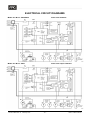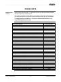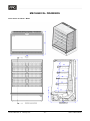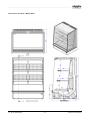
1
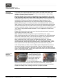
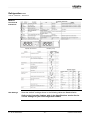
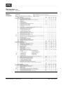
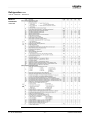
Open Fronted Cabinet Copyright © February 2015 Future Products Group Limited. All rights reserved. No part of this publication may be reproduced, stored in a retrieval system, or transmitted in any form or by any means, electronic, mechanical, photocopying, recording or otherwise, without the prior written permission of Future Products Group Ltd. Part No. 20862 Rev. G February 2015 -2- Visair+ Chilled Cabinets Table of Contents INTRODUCTION ................................................................................................................. 6 Welcome ........................................................................................................................................................... 6 Future Products Group (FPG) .................................................................................................................... 6 Guidance and Help ..................................................................................................................................... 6 Warranty ........................................................................................................................................................... 6 Warranty Period.......................................................................................................................................... 6 Liability Exceptions ..................................................................................................................................... 7 Specific Exclusions ..................................................................................................................................... 7 Assessment ................................................................................................................................................ 7 Time Limit ................................................................................................................................................... 7 Caution ....................................................................................................................................................... 7 OPERATION ....................................................................................................................... 8 Cabinet Layout ................................................................................................................................................. 8 Visair Cube ................................................................................................................................................. 8 Controls & Indicators ...................................................................................................................................... 9 Power Switch and Indicator Lamps ............................................................................................................ 9 Status Indicators ......................................................................................................................................... 9 Refrigeration Controller .............................................................................................................................. 9 Spillage Tray............................................................................................................................................... 9 Preparation ..................................................................................................................................................... 10 Shelf Location and Ticketing .................................................................................................................... 10 Shelf Adjustment ...................................................................................................................................... 10 Shelf Loading Position .............................................................................................................................. 10 Switch Power On ...................................................................................................................................... 11 Load Cabinet ............................................................................................................................................ 11 Air Baffle Plates ........................................................................................................................................ 11 Loading Restrictions ................................................................................................................................. 11 Defrost Cycle ............................................................................................................................................ 11 Routines ......................................................................................................................................................... 12 After Hours ............................................................................................................................................... 12 Cleaning ................................................................................................................................................... 12 De-frost Cycle ........................................................................................................................................... 12 Temperature Checks ................................................................................................................................ 12 TROUBLE SHOOTING ..................................................................................................... 13 Boil-off /Pump Failure LED illuminated..................................................................................................... 14 Thermal Cut-out Tripped .......................................................................................................................... 14 Water present, but no heating .................................................................................................................. 14 Lights not working..................................................................................................................................... 15 Carel Controller Display Alarm Codes...................................................................................................... 15 LED status indicator lamps ....................................................................................................................... 15 Fault remedies .......................................................................................................................................... 15 CLEANING ........................................................................................................................ 16 Cautions ......................................................................................................................................................... 16 Power ....................................................................................................................................................... 16 Water ........................................................................................................................................................ 16 IN – M11C-B003/004/007 -3- © Future Products Group Exterior ........................................................................................................................................................... 16 Louvers ..................................................................................................................................................... 16 Painted and Metal Surfaces ..................................................................................................................... 16 Glass ........................................................................................................................................................ 16 Interior............................................................................................................................................................. 17 Side Glass ................................................................................................................................................ 17 Shelf Trays ............................................................................................................................................... 17 Spillage Tray............................................................................................................................................. 17 Base Trays and Air Baffles ....................................................................................................................... 17 Back Plates ............................................................................................................................................... 17 Cleaning the Base Cavity ......................................................................................................................... 18 Fan Deck .................................................................................................................................................. 18 Condensate Pump Intake Filter ................................................................................................................ 18 Condensate Capacity Warning ................................................................................................................. 18 Cleaning Materials .................................................................................................................................... 18 Cooling Coil and Probes ........................................................................................................................... 19 Mandatory Cleaning Routines ...................................................................................................................... 20 Warning .................................................................................................................................................... 20 Condenser Radiator ................................................................................................................................. 20 Condenser Fans and Air Duct .................................................................................................................. 20 Inspection and Rectification ..................................................................................................................... 20 INSTALLATION ................................................................................................................ 21 Regulations .................................................................................................................................................... 21 Compliance with Local Requirements ...................................................................................................... 21 Setting Up ....................................................................................................................................................... 21 Unpacking ................................................................................................................................................. 21 Cabinet Preparation.................................................................................................................................. 21 Positioning the Cabinet ............................................................................................................................ 21 Condensate Disposal ............................................................................................................................... 21 Power Supply and Earthing ...................................................................................................................... 22 Isolation .................................................................................................................................................... 22 Location .......................................................................................................................................................... 22 Ventilation ................................................................................................................................................. 22 Draughts ................................................................................................................................................... 22 SERVICING ....................................................................................................................... 23 Electrical Protection ...................................................................................................................................... 23 Circuit Breaker .......................................................................................................................................... 23 Lighting ........................................................................................................................................................... 23 Caution ..................................................................................................................................................... 23 Fluorescent Tubes .................................................................................................................................... 23 Test ........................................................................................................................................................... 23 Part No. 20862 Rev. G February 2015 -4- Visair+ Chilled Cabinets Refrigeration Equipment ............................................................................................................................... 24 Caution ..................................................................................................................................................... 24 Equipment Chassis................................................................................................................................... 24 Control Gear ............................................................................................................................................. 24 Ventilation Fan.......................................................................................................................................... 24 Evaporator Fan Replacement .................................................................................................................. 25 Evaporator Coil and Accumulator ............................................................................................................. 25 Condenser Fan Replacement .................................................................................................................. 25 Condenser Radiator ................................................................................................................................. 25 Air Ducts and Grills ................................................................................................................................... 26 Temperature Regulator ............................................................................................................................ 26 MPXPRO Controller Adjustment .............................................................................................................. 26 Caution: .................................................................................................................................................... 26 Condensate Pump .................................................................................................................................... 27 Automatic Condensate Removal, (ACR) Unit .......................................................................................... 27 ACR Fault Finding Guide ......................................................................................................................... 28 Condensate Element Replacement.......................................................................................................... 28 MPXPRO Functions & Indications ............................................................................................................ 29 FPG Settings ............................................................................................................................................ 29 MPXPRO Parameters .............................................................................................................................. 30 MPXPRO Connections ............................................................................................................................. 32 Mains Lead ..................................................................................................................................................... 32 Lead Replacement ................................................................................................................................... 32 SPECIFICATIONS ............................................................................................................. 33 Mechanical ..................................................................................................................................................... 33 Electrical ......................................................................................................................................................... 33 Controller Settings ........................................................................................................................................ 34 Changes from Carel Defaults ................................................................................................................... 34 Carel MPX PRO Settings ......................................................................................................................... 34 Compliance .................................................................................................................................................... 35 Safety Aspects .......................................................................................................................................... 35 Operational Safety .................................................................................................................................... 35 Refrigerated Section Performance Aspects ............................................................................................. 35 Improvements ................................................................................................................................................ 35 Ongoing Development .............................................................................................................................. 35 ELECTRICAL CIRCUIT DIAGRAMS ................................................................................ 36 Model: IN - M11C - B003/B004 ................................................................................................................ 36 Model: IN - M11C - B007 .......................................................................................................................... 36 SPARE PARTS ................................................................................................................. 37 Cabinet Serial Number ............................................................................................................................. 37 MECHANICAL DRAWINGS .............................................................................................. 38 Inline Visair IN - M11C - B003 ................................................................................................................. 38 Inline Visair IN - M11C - B004 / B007 ................................................................................................... 39 IN – M11C-B003/004/007 -5- © Future Products Group INTRODUCTION Welcome VISAIR+ CABINETS - INTRODUCTION Future Products Group (FPG) Welcome to the world of FPG! Our products are designed and engineered to give you the optimal performance that you deserve with innovative visual merchandising appeal. We are confident that you will be delighted with your state of the art Inline Visair food service cabinet, and that it will become a valued appliance in your store. Guidance and Help Any new appliance can seem very complex and confusing at first glance. To ensure you receive the utmost benefit from your new Inline Visair cabinet, there are two things you can do. Before operating the cabinet, please read the instruction book carefully and follow its recommendations. The time taken will be well spent. These instructions both general and technical tell you how to operate and look after your Inline Visair food service cabinet so that you can receive the full benefits that this cabinet has to offer. These instructions cannot, however, cover all eventualities. If you are unsure of any aspect of the installation, instructions or performance of your cabinet, contact your dealer promptly or contact us via email to [email protected]. Warranty VISAIR+ CABINETS - INTRODUCTION Warranty Period Future Products Group Limited warrants, to the original purchaser of an FPG manufactured food service cabinet that for ONE YEAR (12 months), from the date of purchase, any defect in workmanship or material resulting in the product malfunctioning while under correct use will be rectified. Liability under this warranty is limited to replacing or repairing a part, without charge. Continued on next page Part No. 20862 Rev. G February 2015 -6- Visair+ Chilled Cabinets Warranty cont. VISAIR+ CABINETS - INTRODUCTION Liability Exceptions Specific Exclusions Liability under this warranty does not include: Any loss, or damage or expenses directly or indirectly arising from use or inability to use the product or from any other cause. Any part of the cabinet which has been subject to misuse, neglect, alteration, incorrect installation, accident, or damage caused by transportation, use of abrasive or caustic chemicals, flooding, fire or acts of God. Damage, resulting from failure to have the cabinet regularly serviced every three months by a refrigeration engineer. NB: You will be required to provide copies of service records in the event of compressor failure. Any damage or malfunction resulting from the use of non-FPG supplied spare parts. The following are specifically excluded from warranty: Breakage of glass or plastic components or the replacement of fluorescent tubes or gaskets. Maladjustment of the electronic refrigeration controller, by an unqualified person. Failure resulting from a lack of routine compressor / radiator cleaning. Failure to re-assemble the cabinet correctly after cleaning. Fair wear and tear. Assessment The liability under this warranty is dependent on an assessment by FPG, to determine the defect in workmanship or materials. Time Limit FPG does not guarantee that any service to be performed under this warranty will be carried out within any particular time limit. Caution No warranty claim will be accepted unless authorised by FPG prior to commencement of service. IN – M11C-B003/004/007 -7- © Future Products Group OPERATION Cabinet Layout VISAIR+ CABINETS - OPERATION Visair Cube This is a stand-alone, open fronted cabinet, with glass side panels and a top fluorescent light. Various shelf configurations are available to accommodate different package sizes. Cabinets are fully self-contained, with an integral refrigeration unit. They are fitted with a condensate disposal pump, which can either discharge into a drain or a rear mounted condensate boil-off unit. The controls and refrigeration equipment are mounted in the base of the cabinet. Cooling air for the refrigeration system is drawn in from the top of the cabinet, where the air is cleaner than at floor level. Part No. 20862 Rev. G February 2015 -8- Visair+ Chilled Cabinets Controls & Indicators VISAIR+ CABINETS - OPERATION Power Switch and Indicator Lamps The main power switch is mounted in the top of the front base panel, on the right hand side. This is the only operator control, and it switches the lighting and refrigeration on and off. Indicator lamps show the operational state of the cabinet. Status Indicators ON Element Failure Defrost Boil-off or Pump Failure Operational Problem Refrigeration Controller The refrigeration controller is mounted on the right hand side of the equipment chassis in the base of the cabinet. The front panel must be unscrewed to access the controller. The controller is pre-set for correct cabinet functioning, and must only be adjusted by a qualified service person. Spillage Tray The spillage containment tray in the bottom of the display area is fitted with a drain plug. Be sure to have the plug in place during normal cabinet use, to prevent spillages running into the cabinet well. To drain spillages, pull the base drawer forward, and place a receptacle under the drain before removing the plug. IN – M11C-B003/004/007 -9- © Future Products Group Preparation VISAIR+ CABINETS - OPERATION Shelf Location and Ticketing All shelves are adjustable in height and can easily be moved up or down, to match product size. The front edges of the shelves are profiled to carry ticketing/labels. Shelf Adjustment To alter the shelf position, slide the brackets upwards and disengage them from the support pillar. Insert the brackets in the new position and push them down firmly. The brackets can be inserted in two positions, allowing the shelves to be either horizontal or sloping downwards. Make sure shelf brackets are pushed down as far as they can go. Failure to do this may result in shelf collapse, when loaded with product. Shelf Loading Position Each shelf is fitted with runners, enabling it to be pulled forward for easy loading. Using two hands, depress the two locking bars located under the front edge of the shelf, to release it. When returning the shelf to its normal position, push it in firmly, until both locking bars latch into position. Part No. 20862 Rev. G February 2015 - 10 - Visair+ Chilled Cabinets Preparation cont. VISAIR+ CABINETS - OPERATION Switch Power On Turn on the power switch, the compressor will run, and the cabinet temperature will begin to fall. The temperature controller is pre-set to maintain the cabinet temperature at 2 - 4C. It should not need adjustment. Load Cabinet After the cabinet has run for a 30 minute initial cool-down period, load it with pre-chilled product. The cabinet is designed to maintain the temperature of pre-chilled product at between 2 and 4C. If warm product is introduced, there could be a delay before the temperature falls to the normal operating level. Air Baffle Plates If low profile products are displayed on any shelf, fit an air baffle plate to block the upper back panel air slots behind that shelf. This will maintain correct cool air flow among the products. The plate should be fitted in the location slots immediately below the shelf brackets. Loading Restrictions It is important to leave adequate free space for the refrigerated air to circulate within the cabinet. The air grills at the front of the cabinet must not be covered or restricted. Defrost Cycle Defrosting of the evaporator coil is fully automatic. Measurements of air and coil temperatures control the commencement and duration of the defrost cycles. This active defrost system improves the energy efficiency of the cabinet, and minimises temperature fluctuations. IN – M11C-B003/004/007 - 11 - © Future Products Group Routines VISAIR+ CABINETS - OPERATION After Hours Ideally, cabinets should not be turned off after hours or at night. If the cabinet is turned off, transfer the products to a cool store. When the cabinet is turned on again, allow it to run for 30 minutes before returning the chilled products. Cleaning It is recommended that cabinets be cleaned at the end of the working day, since they need to be shut down for this. See Cleaning section. De-frost Cycle Defrosting of the evaporator coil is fully automatic. Measurements of air and coil temperatures control the commencement and duration of the defrost cycles. This active defrost system improves the energy efficiency of the cabinet, and minimises temperature fluctuations. If you suspect that the defrost system is not working properly, have it checked by a qualified service person. Operators must not attempt to adjust the refrigeration controller. Temperature Checks Cabinet temperatures should be routinely checked, to confirm satisfactory operation. All cabinets are fitted with thermometers, to give an indication of air temperature, but a temperature probe should be used to check package temperatures. To avoid misleading temperature measurements, do not take a reading if the DEFROST indicator light is ON. Part No. 20862 Rev. G February 2015 - 12 - Visair+ Chilled Cabinets TROUBLE SHOOTING FAULT POSSIBLE CAUSE The mains isolating switch on the wall, circuit breaker or fuses are off at the power board The power switch on the cabinet is OFF The internal MCB has tripped off or failed The power switch is faulty Boil-off system has failed Ventilation grills are blocked Product blocking air grill Thermostat needs adjustment Ambient temperature > 25C Cabinet does not operate/start Evaporator coil iced up Refrigerated Cabinet does not reach temperature Condenser radiator blocked Refrigeration controller faulty Temperature probe damaged Fans not operating HP pressure switch triggered LP pressure switch triggered REMEDY Turn isolating switch circuit breaker or fuses on Turn the power switch ON Have wiring checked and reset or replace breaker Have the switch replaced See detailed instructions below Vacuum or remove blockage Place product on shelves Adjust refrigeration controller Adjust store air conditioning De-ice coil, check active defrost parameters, replace controller if found faulty Remove dust and debris Replace controller Replace temperature probe Have fans checked/replaced Manually reset switch Allow switch to auto reset. If it doesn’t reset, check for leaks (Clear the alarm indication, by turning off the power to reset the controller) Condensate Overflows Cabinet lights not working Aluminium parts corroded Service Personnel Only Condensate pump failed Pump filter blocked Pump water level switch faulty Boil-off control module failed Fluorescent tube failed There is a cabinet fault alarm The internal MCB has tripped off or failed Caustic detergent damage Have the pump replaced Clean the filter Check/replace unit Check/replace control module Replace fluorescent tube See additional information below Have wiring checked and reset or replace breaker Order replacement parts The table entries in italics indicate actions to be taken only by qualified Service Personnel. IN – M11C-B003/004/007 - 13 - © Future Products Group TROUBLE SHOOTING continued Boil-off /Pump Failure LED illuminated If the cabinet shuts down and the Boil-off/Pump fail LED fault light is lit, then either the condensate pump has failed or the boil-off element thermal cut-out will have tripped. Thermal Cutout Tripped Check if the probe in the boil-off tank is dirty and needs cleaning (a dirty probe can complete a circuit to earth causing the unit to think water is still present and keep the element powered up) clean if required. Check if the probe in the boil-off tank is bent or incorrectly positioned and touching the side of the tank - (this will complete a circuit to earth causing the unit to think water is still present and keep the element powered up) repair as required. Check if the control unit is faulty and continues to give an out-put to the element relay when no water is present. Disconnect the probe wire from terminal "S+" on the control unit. If it continues to output 230V on terminal "L1" after 10 seconds, replace the control unit. Water present, but no heating Part No. 20862 Rev. G If the boil-off element does not come on even though water is present and touching the bottom of the sensor probe, check the following: Check for 230V across the element, if there is 230V across the element and the element does not heat replace the element. If the thermal cut-out has 230V supply, try resetting the thermal cut-out. If the thermal cut-out won't reset replace it. If 230V is not present at the thermal cut-out, check if the element relay has 230V supply to its contacts. If no power is present at the switched terminals, check the cabinet power supply. If 230V power is present on the switched terminals, check if the relay coil has 230V power across the coil terminals. If there is 230V across the element relay coil terminals, replace the relay. If 230V power is not present across the element relay coil terminals, check for a 230V out-put from the control unit terminal "L1". If 230V power is not present, check for a 230V power supply into the control unit on terminal "L". If 230V power is present on the control unit terminal "L", check the unit by shorting out the sensor terminals "S+" & "S-". If after shorting sensor terminals "S+" & "S-" the unit does not provides a 230V output on terminal "L1", replace the control unit. If the control unit does provide a 230V output on terminal L1 then the sensor wiring and sensor need to be checked. Check the sensor wiring for continuity and repair or replace if open circuit. Check the probe in the boil-off tank for dirt build-up over its surface (this can act as an insulator), clean as required. February 2015 - 14 - Visair+ Chilled Cabinets TROUBLE SHOOTING continued Lights not working When a cabinet alarm condition is present, the cabinet lights will go out to alert staff of the alarm condition. To determine the cause of the alarm condition, check the Carel controller display and the LED status indicator lamps. Carel Controller Display Alarm Codes Alarm code “IA” indicates the fault is due to the refrigeration high-pressure switch or low-pressure switch, tripping open circuit. LED status indicator lamps “Boil-off/Pump failure” indicator lamp lit. This indicates that the fault is due to the drain pan condensate pump float switch, reaching its high water level limit. Alarm code “dA” indicates the fault is due to the drain pan condensate pump float switch, reaching its high water level limit. “Operational problem” indicator lamp lit. This indicates that the fault is due to the refrigeration high-pressure switch or low-pressure switch, tripping open circuit. Fault remedies For “IA” and “Operational problem” lamp fault indication, carry out the following: Check for obstruction to the condenser airflow in and out of the cabinet and rectify as required. Check and clean the condenser coil if required. Check the refrigeration system operating gas pressures and rectify any faults as required. For “dA” and “Boil-off/pump failure” lamp fault indication, carry out the following: IN – M11C-B003/004/007 Check the condensate pump pick up filter is not blocked, clean as required. Check the operation of the condensate water pump and repair/replace as required. Check the operation of the boil-off element, thermal cutout and element controller. Repair, reset or replace as required. If no fault can be found with the above, drain the excess condensate water from the system by disconnecting the blue plastic pipe from the boil-off and place the end in a suitable container. Turn cabinet power on and the pump will pump the water out of the cabinet into the container. Turn the cabinet off and re-connect the blue pipe to the boil-off. Turn the cabinet back on and check for correct operation. Most likely the excess water was caused by an iced up evaporator coil. Check for likely causes of an iced up evaporator coil. - 15 - © Future Products Group CLEANING Cautions VISAIR+ CABINETS - CLEANING Power ALWAYS TURN THE POWER SUPPLY OFF BEFORE CLEANING. Water THIS UNIT IS NOT WATERPROOF. DO NOT USE A WATER JET SPRAY TO CLEAN THE INTERIOR OR EXTERIOR OF THIS CABINET. Exterior VISAIR+ CABINETS - CLEANING Louvers Use a vacuum cleaner to remove dust and fluff from the ventilation louvers on the top of the cabinet. This will maintain the refrigeration efficiency, and prevent overheating. Painted and Metal Surfaces Painted, galvanised steel or aluminium surfaces should be cleaned with hot soapy water then dried off with paper towel or dry cloth. DO NOT clean surfaces with abrasive pads or cleaners as paint, galvanised steel and aluminium surfaces will be damaged. Glass All glass should be cleaned using a good quality glass cleaner and a clean cloth. DO NOT clean glass with abrasive pads or cleaners as the glass will be damaged. Part No. 20862 Rev. G February 2015 - 16 - Visair+ Chilled Cabinets Interior VISAIR+ CABINETS - CLEANING Side Glass The inside surfaces of the side panels are most easily cleaned after the products and shelves have been removed. Shelf Trays The shelf trays are easily lifted off for cleaning. The complete shelf module can also be removed by lifting it vertically, to disengage the support brackets from the back panel. Spillage Tray If there is liquid in the spillage tray, pull the base drawer forward, and place a receptacle under the drain, before removing the plug. If spillages contaminate the well, pump and boil-off unit, objectionable smells will result. Base Trays and Air Baffles Base trays are easily removed, using the two finger holes. To remove air baffle plates, simply slide upwards and pull forwards, to disengage from the slots in the shelf pillars. Back Plates Once the shelves and brackets have been removed, and the base drawer slightly opened, the back plates can be removed. Lift the plate vertically, to disengage it from the bottom location slot, pull it forward, then lower it to disengage it from the top location slot. It can now be removed for cleaning. Continued on next page IN – M11C-B003/004/007 - 17 - © Future Products Group Interior cont. VISAIR+ CABINETS - CLEANING Cleaning the Base Cavity The cabinet base is mounted on runners, and can be pulled forwards to access the base cavity. Sweep out, or use a vacuum cleaner, to remove any debris. A Wet-and-Dry vacuum cleaner should be used, since there is likely to be some water in the bottom. Fan Deck The fan deck is not fixed, and can be lifted up, unplugged and removed for cleaning. Condensate Pump Intake Filter Lift the lid off the condensate pump intake filter and remove any debris. Condensate Capacity Warning The pump control switch is operated by a magnet, mounted on a float. Be sure to fit the float with the magnet against the lid, when it is replaced. The condensate pump and boil off heater is only designed to handle cooling-coil defrosting water that drains from the well during normal operation. The boil off container has a capacity of two litres. When cleaning, DO NOT fill the well with liquid, or attempt to hose it out. The condensate pump only operates when the main switch is on, so the well will not empty until the power is switched on again. Cleaning Materials Steel trays, shelves, grills etc. should be cleaned with hot soapy water then dried off with paper towel or dry cloth. DO NOT use abrasive pads or cleaners as these may damage surfaces. Warning: Dishwasher detergent may damage anodised aluminium parts. Continued on next page Part No. 20862 Rev. G February 2015 - 18 - Visair+ Chilled Cabinets Interior cont. VISAIR+ CABINETS - CLEANING Cooling Coil and Probes With the back plates removed, the cooling coil is exposed. No cleaning is normally required, but if there is any debris visible, carefully remove it with a vacuum cleaner. Be very careful not to bend or distort the fins of the cooling coil, as this would reduce the airflow. Also be careful not to move or disturb the location of the two temperature probes. IN – M11C-B003/004/007 - 19 - © Future Products Group Mandatory Cleaning Routines VISAIR+ CABINETS - CLEANING Warning It is mandatory to have the radiator fins cleaned periodically, by a refrigeration engineer. (see Servicing section). Failure to carry out routine cleaning/servicing schedules will void the warranty on the refrigeration equipment. To maintain optimum performance, cleaning must be regular and thorough. It is recommended that a schedule of cleaning operations should be drawn up. Condenser Radiator For efficient refrigeration performance, the condenser radiator must be clean. To access the radiator, the bottom panel must be removed from the back of the cabinet, so this would normally be done by a service person, rather than the operator. Be careful not to disturb the location of the air temperature sensing probe. Condenser Fans and Air Duct The bottom side panels must be removed to access the two condenser fans, so this would also normally be done by a service person. The fan units pull out from either side of the cabinet, and can be unplugged and taken away for easy cleaning. Vacuum away any dust and fluff in the duct. Inspection and Rectification As part of the cleaning routine, the controls, mechanical parts and electrical wiring should be inspected for damage, deterioration or need of adjustment. If any small faults are found, have them attended to promptly by a competent serviceman. Don’t wait until they cause a complete breakdown. Part No. 20862 Rev. G February 2015 - 20 - Visair+ Chilled Cabinets INSTALLATION Regulations VISAIR+ CABINETS - INSTALLATION Compliance with Local Requirements It is very important that your food cabinet is installed correctly and is operating properly before use. Installation must comply with local electrical, health & safety and hygiene requirements. Setting Up VISAIR+ CABINETS - INSTALLATION Unpacking Unpack and check unit for damage and report any damage to the carrier and supplier. Report any deficiencies to your supplier. Cabinet Preparation Remove all tapes, ties and packers, used to prevent movement during transit. Pull the base drawer open to check for packing materials in the well. Positioning the Cabinet Position the cabinet in its allocated working position. There are casters on either side at the back, so it can be easily manoeuvred by lifting the front. Using a spirit level, adjust each front foot to ensure the cabinet is level from front to back and side to side. If the floor is not level, place packing under one of the castors. Condensate Disposal Condensate water can be disposed of by pumping it either to a drain or to the integral boil off unit. The cabinet is delivered with the pump feeding the boil off unit. To pump the condensate to a drain, the blue pipe must be disconnected and spliced to the pipe leading to the drain. Continued on next page IN – M11C-B003/004/007 - 21 - © Future Products Group Setting Up cont. VISAIR+ CABINETS - INSTALLATION Power Supply and Earthing Each cabinet is fitted with a three-pin IEC connector and a three metre mains lead. If the cabinet is to be hard wired, this must only be done by a suitably qualified person. Before connecting to the power supply, check that the local supply is correct to that shown on the cabinet label. WARNING - EACH CABINET MUST BE EARTHED/GROUNDED Isolation If the cabinet is not connected to an outlet socket, but is hard wired to the mains supply, a means of isolation must be provided. If a plug and socket are used, they should still be accessible after the cabinet is installed. Location VISAIR+ CABINETS - INSTALLATION Ventilation The vents located on the top of the cabinet must never be obstructed. If obstructed the cabinet may overheat and cause an electrical malfunction. Before use, operate the cabinet for 1-2 hours to remove any fumes or odours, which may be present. Draughts The door-less cabinet features an “air curtain” to retain the cold air within the cabinet. A “curtain” of cold air falls from a linear vent, across the top of the open cabinet front, to be recirculated through the evaporator cooling coils. The cabinet should not be sited where strong draughts will deflect the “air curtain”. If this happens, excess condensation will form on the products, and cooling will be less effective. Draughts across the top of the cabinet can cause recirculation of warm exhaust air back into the inlet grill. This will reduce the operating efficiency of the refrigeration system. Part No. 20862 Rev. G February 2015 - 22 - Visair+ Chilled Cabinets SERVICING Electrical Protection VISAIR+ CABINETS - SERVICING Circuit Breaker The lighting circuit is protected by a circuit breaker, located on the control gear chassis. The circuit breaker is accessible through a hole in the side of the chassis. If the breaker cannot be reset, call an electrician to check the circuits. Lighting VISAIR+ CABINETS - SERVICING Caution DO NOT service the lights, without isolating the cabinet at the main switch or unplugging it from the electricity supply. Fluorescent Tubes Remove the plastic diffuser from the metal extrusion to access the fluorescent tube. Rotate the tube by 90°, to release it. After changing the tube, replace the plastic diffuser. Locate one edge of the diffuser strip in the extrusion groove, and curve it into the other groove. Test Turn the power on and test lighting operation. If normal operation cannot be restored, by replacing the tube, call an electrician. IN – M11C-B003/004/007 - 23 - © Future Products Group Refrigeration Equipment VISAIR+ CABINETS - SERVICING Caution DO NOT attempt to service the refrigeration equipment without isolating the cabinet from the mains supply. Equipment Chassis The compressor, control gear chassis and condensate pump are mounted in the base of the cabinet. Unscrew the front panel to gain access. To the right of the cavity, an enclosed sub-chassis houses the refrigeration controller, lighting ballast, MCB, compressor starting capacitor and relay, and compressor running capacitor. The control panel of the MPXPRO is mounted on the front of the chassis, and the main switch and indicator LEDs are mounted on the top. A circuit diagram and Product Manual are located on the back of the front panel. Control Gear Unscrew the front panel to access the control gear. This assembly is part of the water sensing circuit. This is the MPXPRO controller circuit. Ventilation Fan The fan, mounted on the front panel, draws fresh air in through the grill on the top of the panel. The air cools the compressor, eliminates condensation, and exits from the right hand side of the grill. The fan runs at all times, and it is important that the grill is kept clear of dust and fluff. Unplug the fan to remove the front panel. Continued on next page Part No. 20862 Rev. G February 2015 - 24 - Visair+ Chilled Cabinets Refrigeration Equipment cont. VISAIR+ CABINETS - SERVICING Evaporator Fan Replacement The fan deck is not fixed in place, and can be unplugged to replace a faulty fan. The fan speed is electronically programmed, so the correct spare must be used. Evaporator Coil and Accumulator The evaporator coil and accumulator are accessed by removing the inside back panels of the cabinet, see Cleaning. Take care not to disturb the location of the two probes. One is in the air flow, the other in the coil fins. Condenser Fan Replacement To access the condenser fans, remove the side panels from the base of the cabinet. Each fan is located on a pull-out chassis, one on each side of the cabinet. They can be withdrawn and unplugged for servicing. Condenser Radiator The condenser radiator runs across the bottom of the cabinet, at the back. It is accessed by removing the rear panels. It is vital that the radiator is kept clean. If air flow is restricted, refrigeration efficiency will be poor. The radiator fins must be regularly cleaned, using compressed air. Be careful not to disturb the location of the probe, which measures the temperature of the air leaving the radiator. Continued on next page IN – M11C-B003/004/007 - 25 - © Future Products Group Refrigeration Equipment cont. VISAIR+ CABINETS - SERVICING Air Ducts and Grills All air ducts and grills must be regularly vacuumed, to keep them free of dust and fluff. This is best done with the condenser fans withdrawn, and after cleaning the radiator with compressed air. Grills are located on the top of the cabinet and along the top edge of the front bottom panel. Temperature Regulator The Carel MPXPRO regulator consists of two parts. A circuit board, mounted inside the control gear chassis, and an indicator/control panel on the front of the chassis. The regulator controls the cabinet temperature, the defrost cycles and monitors cabinet operation. The unit is factory set as per the table in the Specification section. Two temperature probes are used to control the defrost cycles, one in contact with and the other adjacent to the evaporator coils. A third probe monitors the temperature of the air leaving the condenser radiator. MPXPRO Controller Adjustment Caution: This controller should only be adjusted by a qualified service technician. The indicated temperature will be lower than the air temperature inside the cabinet, because the refrigeration compressors are controlled in response to the exit air temperature from the evaporator cooling coils. A second probe is inserted in the fins of the evaporator coil. This provides temperature information to control the defrost functions. Incorrect adjustment or accidental movement of the probes can cause the fins to ice up, resulting in reduced airflow and poor performance. Continued on next page Part No. 20862 Rev. G February 2015 - 26 - Visair+ Chilled Cabinets Refrigeration Equipment cont. VISAIR+ CABINETS - SERVICING Condensate Pump The pump is activated by a float switch in the inlet filter module, and also provides a monitor signal to the MPXPRO controller. If the pump is not working, make sure that the float switch is assembled with the magnet towards the under side of the lid. Automatic Condensate Removal, (ACR) Unit The ACR unit is located at the back of the cabinet, behind the back panels. The main tank has an immersion heating element, and a coupled side tank houses a water sensing probe. Power is switched to the element when water is sensed by an electronic sensor. In the event that the element remains on with no water present in the boil-off tank, a manual reset thermal cut out mounted on the side of the tank will trip open circuit at 120°C. It can be reset when the temperature falls below 84°C. If the thermal cut-out is not reset and the cabinet continues to operate normally, the boil-off will overfill allowing the condensate water to return to the bun. The bun will then overfill with water and activate the condensate pump high water level sensor. This will then shut down the cabinet, activate an alarm and bring on the Boil-off/Pump fail indicator light. Continued on next page IN – M11C-B003/004/007 - 27 - © Future Products Group Refrigeration cont. VISAIR+ CABINETS - SERVICING ACR Fault Finding Guide First check if the condensate water level probe in the ACR tank is dirty and needs cleaning (a dirty probe may either fail to detect water, or give a false indication of water) clean if required. If the sensitivity is set too low, the Finder Level Control unit may not detect the condensate water and won’t switch on the ACR element. If the sensitivity is set too high, the Finder Level Control unit may get a false indication of the condensate water and switch on the ACR element without water present. Fault: ACR element is on continuously when no condensate water is present. Test: Check if the Finder Level Control unit is faulty by disconnecting the probe wire from terminal B1 on the Finder Level Control unit. With the cabinet power turned on and after waiting 10 seconds, check for 230V across terminals 11 and 14. If 230v is not present across terminals 11 & 14, replace the Finder Level Control unit. Fault: ACR element does not heat even though condensate water is present and touching the water level probe. Test: Check if the Finder Level Control unit has a 230V power supply. Next, check the manual re-set Thermal Cut-out, located on the lower right hand side of the ACR heater tank, at the rear of the cabinet. If the Thermal Cut-out won’t re-set and remains open circuit, replace the Thermal Cut-out. Next, check the Finder Level Control unit water sensing circuit, by shortcircuiting the level sensor terminals B1 & B3. Turn the cabinet power on and wait 10 seconds, check if the ACR element heats. If the element heats, check for an open circuit in the water sensing probe circuit and clean the probe. If the element does not heat, turn the cabinet power off and take the element wire out of terminal 11 and wire into terminal 14 on the Finder Level Control unit. Turn the cabinet power on and wait 10 seconds, check if the ACR element heats. If the element heats, replace the Finder Level Control Unit. If the element does not heat replace the element. Condensate Element Replacement To replace the element, remove the safety cover, and squeeze the sides of the element together to disengage it from the mounting bracket. Cut the feed cables at the heat-shrink covered connection and remove the old element. Insert and connect a new element, fitting new heat-shrink sleeves over the connections. Replace the safety cover, making sure that it is properly located. Continued on next page Part No. 20862 Rev. G February 2015 - 28 - Visair+ Chilled Cabinets Refrigeration cont. VISAIR+ CABINETS - SERVICING MPXPRO Functions & Indications FPG Settings Note that “default” settings shown in the following tables are Carel defaults. Refer to the Controller Settings table in the Specifications section for the correct settings for your FPG refrigerated cabinet. Continued on next page IN – M11C-B003/004/007 - 29 - © Future Products Group Refrigeration cont. VISAIR+ CABINETS - SERVICING MPXPRO Parameters Continued on next page Part No. 20862 Rev. G February 2015 - 30 - Visair+ Chilled Cabinets Refrigeration cont. VISAIR+ CABINETS - SERVICING MPXPRO Parameters continued Continued on next page IN – M11C-B003/004/007 - 31 - © Future Products Group Refrigeration cont. VISAIR+ CABINETS - SERVICING MPXPRO Parameters continued MPXPRO Connections Mains Lead VISAIR+ CABINETS - SERVICING Lead Replacement Part No. 20862 Rev. G If damaged, the mains lead must ONLY be replaced by a qualified service person. February 2015 - 32 - Visair+ Chilled Cabinets SPECIFICATIONS Mechanical VISAIR+ CABINETS - SPECIFICATIONS CABINET MODEL IN-M11CB003 IN-M11CB004 Height mm 1479 1479 Width mm 1096 1096 Depth mm 830 830 Dry Weight kg 272 272 Powder-coated steel Powder-coated steel 8 4 1.5 (shelves) + 0.4 (base) 0.8 (shelves) + 0.4 (base) R404A R404A Cabinet Well Material Number of Shelf Modules Display Area m2 Refrigerant Refrigerant Charge Condensate capacity Climatic Class & IP Rating IN-M11CB007 Refer to cabinet Serial No./Rating label 1.7 litres 1.7 litres All cabinets are suitable for class N climates and have an IP 22 rating Electrical VISAIR+ CABINETS - SPECIFICATIONS CABINET MODEL IN-M11CB003 IN-M11CB004 Voltage Power Energy Consumption Current Connection Temperature Range, C Fluorescent Lamps IN – M11C-B003/004/007 IN-M11CB007 230-240 V 50 Hz 1 1.7 kW 1.7 kW 1.2 kWh/h 1.2 kWh/h 8.6A 8.6A Three core cable Three core cable 2 - 4 1 x 30W (Colour 84) 2 - 4 1 x 30W (Colour 84) - 33 - © Future Products Group Controller Settings VISAIR+ CABINETS - SPECIFICATIONS Changes from Carel Defaults The following table specifies the controller settings which differ from the Carel default values. Parameters not listed in this table should remain at the default values specified in the MPXPRO Parameters listed in the Servicing section. Carel MPX PRO Settings CABINET MODEL Parameter No IN – M11C Regulation Set Point St -7 Regulation Differential rd 6 Assign intake probe (Sr) /Fc 0 Assign aux probe 1 (Saux1) /FG 3 Select display main terminal /t1 1 Max int. between defrosts dl 2 Defrost end temp dt1 3 Max defrost duration dP1 45 Display during defrost d6 0 Dripping time after defrost dd 0 Defrost time “Running time” d10 10 Defrost temp threshold d11 -10 Config. func. dig. Input DI1 A4 1 Config. func. dig. Input DI2 A5 2 Delay time delayed ext alarm A7 3 Serial address H0 5 Configure AUX 3 H7 2 Part No. 20862 Rev. G February 2015 - 34 - Visair+ Chilled Cabinets Compliance VISAIR+ CABINETS - SPECIFICATIONS Safety Aspects These cabinets have been designed to comply with the relevant requirements of the following specifications: AS/NZS 3100 AS/NZS 3182 AS/NZS 3820 AS/NZS 4417 IEC 60335 Part 1: Part 2-24: EN 55014 Part 1: Part 2: EN 61000 Part 3-2: Part 3: Operational Safety General Requirements for Electrical Equipment Refrigerated Food Commercial Cabinets Essential Safety Requirements Marking of Electrical Products Household and Similar Electrical Appliances – Safety General Requirements Particular Requirements for Refrigerating Appliances / Ice Cream Appliances and Ice Makers Electromagnetic Compatibility Requirements for Household Appliances, Electric Tools and Similar Apparatus Emissions Immunity - Product Family Standard Electromagnetic compatibility (EMC) Limits - Limits for harmonic current emissions (equipment input current up to and including 16A per phase) Limits - Section 3: Limitations of voltage changes, voltage fluctuations and flicker in public low-voltage supply systems, for equipment with rated current ≤ 16A per phase and not subject to conditional connection This appliance is not intended for use by young children or infirm persons, unless they have been adequately supervised by a responsible person, to ensure that they can use the appliance safely. Young children should be supervised, to ensure that they do not play with the appliance. Refrigerated Section Performance Aspects The cabinet is HACCP compliant, with the following performance: Cabinet Operating Temperature Average Internal Humidity Test Conditions +2° to +4°C N/A 25°C Ambient with 60% RH Improvements VISAIR+ CABINETS - SPECIFICATIONS Ongoing Development FPG reserves the right to change specifications and construction, as part of ongoing product improvement. IN – M11C-B003/004/007 - 35 - © Future Products Group ELECTRICAL CIRCUIT DIAGRAMS Model: IN - M11C - B003/B004 Inline Visair Cabinets Model: IN - M11C - B007 Inline Visair Liquor Cabinets Part No. 20862 Rev. G February 2015 - 36 - Visair+ Chilled Cabinets SPARE PARTS Cabinet Serial Number When ordering spare parts, it is important to quote the Serial Number printed on the label fixed to the control panel. This serial number will enable FPG to trace details of the build specification of your particular cabinet, and hence ensure that spare parts are fully compatible. To satisfy warranty conditions, and ensure optimum performance, use only FPG supplied spare parts. Part Description FPG Part No. Adjustable feet Illuminated main switch Mains line filter Lighting filter, DIN rail mounted WH3 Electronic ballast 343 MAU lamp holders 30 watt fluorescent lamp Carel MPX PRO Refrigeration Control display panel Carel MPX PRO Refrigeration Control circuit board unit NTC temperature probe Pressure switch HP manual reset Pressure switch LP auto reset Fan W1G200 evaporator fan Fan R3G190 condenser fan MCB 6A 950 watt high density boil of element Aspen Mini Lime Submersible Pump Condensate Water Sensor, Finder 72.01.8.240.0000 Thermal cut-out Compressor control relay Compressor start relay 30µF 400V motor run capacitor 40µF 400V motor run capacitor 40µF 400V motor start capacitor Deck tray runner Shelf runner Cartguard 3 rigid plastic top stock grey Cartguard 3 rigid plastic end cap stock grey Cartguard 3 rigid plastic corner stock grey Visair cabinet toughened side glass ZS1120 Horizontal scroll compressor ZS7516F1 Horizontal scroll compressor Product Manual for Inline Visair+ Cabinets IN – M11C-B003/004/007 - 37 - 16773 17287 21370 21371 13793 11163 11146 17666 17623 17990 17225 17226 63243 64569 10522 20863 19390 25309 22199 16824 18096 18380 18094 18095 17937 17936 16775 16777 16778 18484 16646 16645 20862 © Future Products Group MECHANICAL DRAWINGS Inline Visair IN - M11C - B003 Part No. 20862 Rev. G February 2015 - 38 - Visair+ Chilled Cabinets Inline Visair IN - M11C - B004 / B007 IN – M11C-B003/004/007 - 39 - © Future Products Group Part No. 20862 Rev. G February 2015