1
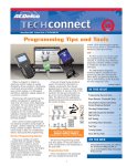
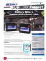
January & February 2012
Battery Killers
Common Causes of Battery Failure
Hot or cold, a harsh environment has a
negative effect on automotive battery life. Slow
cranking, especially during colder weather at this time of year, is often
the first sign of a failing battery.
IN THIS ISSUE
The battery has three functions as a major source of energy:
Battery Killers . . . . . . . . . . . . . . . . . . . . . . . .1
• Engine cranking
OnStar Back-up Battery Activation . . . . .3
• Voltage stabilizer
Duramax Diesel Exhaust
System Fluid Injectors . . . . . . . . . . . . . . . . .4
• Alternate source of energy with generator overload
When replacing a battery, the new battery should match the specifications of the
original battery in order to maintain proper vehicle performance.
New Advanced Powertrain
Technology Seminar . . . . . . . . . . . . . . . . . .5
Battery Ratings
2012 TSS Program Changes . . . . . . . . . . . .6
First 2012 ASE Computer-Based
Testing Session . . . . . . . . . . . . . . . . . . . . . .6
A battery may have three ratings: amperage hours (AH),
reserve capacity (RC), and cold cranking amperage (CCA).
Tech Tips . . . . . . . . . . . . . . . . . . . . . . . . . . . .7
The amperage hour rating is the amount of time it takes
a fully charged battery, being discharged at a constant rate
of 1 amperes and a constant temperature of 80° F (27° C),
to reach a terminal voltage of 10.5 volts. 10.5 V is the fully
discharged level, at which point the battery needs to be
recharged.
Training Update . . . . . . . . . . . . . . . . . . . . . .8
ON THE WEB
Reserve capacity is the amount of time in minutes it
takes a fully charged battery, being discharged at a constant rate of 25 amperes and a
constant temperature of 80° F (27° C), to reach a terminal voltage of 10.5 volts
The cold cranking amperage is an indication of the ability of the battery to crank
the engine at cold temperatures. The cold cranking amperage rating is the minimum
continued on page 2
– www.acdelcotechconnect.com, click
the TechConnect Magazine link, or
– Log in to the ACDelco LMS, click the
Resources link
Battery Killers –
continued from page 1
amperage the battery must maintain
for 30 seconds at 0° F (−18° C) while
maintaining at least 7.2 V.
Volume 19, Number 1 (TS-PU-0005-12)
Electrolyte Freezing
A typical automotive battery is a
flooded cell lead-acid battery. It is
formed when two chemically dissimilar
plates, divided by a separator, are
placed in a solution called electrolyte.
In automotive batteries, one plate is
made of lead and the other of lead
dioxide. The electrolyte is a solution of
64% water and 36% sulfuric acid. A
The chemical composition of the electrolyte
chemical reaction occurs between the
changes as the battery is discharged.
two plates and electrolyte solution that
create approximately 2.1 volts of
electrical energy. As a battery loses its charge, the chemical composition of the
electrolyte changes and it becomes more like water.
The freezing point of electrolyte depends on its specific gravity. A fully charged
battery will not freeze until the ambient temperature gets below −65° F (−54° C).
However, a battery with a low state of charge may freeze at temperatures as high
as 20° F (−7° C). Since freezing may ruin a battery, the battery should be protected
against freezing by keeping it properly charged above 80 percent state of charge,
where the freezing point of the battery will be somewhere below −25° F (−32° C).
Common Causes of Malfunction
Regardless of the environment, a battery is not designed to last forever. With
proper care, however, the battery will provide years of good service. If the battery
tests “good” but still fails to perform well, check for these common causes:
• Vehicle accessories left on after the ignition is turned off
• Regular short trips in stop-and-go traffic, and with many electrical accessories
in use, such as the air conditioning, headlights, wipers, rear window defroster,
etc., that do not allow enough time to properly charge the battery
• The electrical load has exceeded the generator output, particularly with the
addition of aftermarket equipment
• Existing charging system conditions, such as a slipping belt or a generator that
is not in proper working order
• The battery has not been properly maintained, including a loose battery hold
down or missing battery insulator
• Electrical system conditions that draw down battery power
Parasitic Draw
Components most likely to cause a parasitic draw on a vehicle’s battery are
switches, relays and control modules. After the ignition is turned off, the control
modules will begin to go to sleep (shut off). All control modules do not go to sleep
at the same time; some may take up to 30 minutes or longer after turning off the
ignition before going to sleep, like the Body Control Module (BCM). Others modules are designed to periodically wake up, perform a task, and go back asleep at
regular intervals, such as the OnStar and keyless entry control modules. These are
all normal conditions.
For example, an engine off natural vacuum evaporative test can occur if the
Engine Control Module (ECM) determines the drive cycle has met the appropriate
criteria immediately after key off. The ECM will stay awake and the vent solenoid
will stay energized for as long as 45 minutes. The typical current draw for this is
about 1 A.
The remote keyless entry receiver also consumes an extremely low mA current
for monitoring purposes. Actual system wake up only occurs when the key fobs
for the vehicle are used. When other devices on the same remote keyless entry
continued on page 3
2
ACDelco TechConnect is published bi-monthly and
online for technicians of Total Service Support
(TSS) and Key Fleet accounts to provide timely
service information, increase knowledge and
improve the performance of the service center.
ACDelco 360 represents our mission to look at
our businesses at every possible angle to provide
value and assistance to our distributors and
their customers as well as offer a full circle of
support with programs, tools, training and
marketing focused on enhancing and growing
our partnership successfully.
Publisher:
Rick Balabon
ACDelco
E-mail /
[email protected]
Editor:
Greg St. Aubin
ACDelco
E-mail /
[email protected]
Technical Editor:
Mark Spencer
E-mail /
[email protected]
Production Manager:
Marie Meredith
Desktop Publishing:
5by5 Design LLC
E-mail /
[email protected]
Write to: *
ACDelco TechConnect
P.O. Box 500
Troy, MI 48007-0500
On the Web::
To read and search recent issues of
TechConnect online:
– www.acdelcotechconnect.com,
click the TechConnect Magazine
link, or
– Log in to the ACDelco LMS, click
the Resources link
ACDelco service tips are intended for use by
professional technicians, not a “do-it-yourselfer.”
They are written to inform those technicians of
conditions that may occur on some vehicles, or to
provide information that could assist in the proper
service of a vehicle. Properly trained technicians
have the equipment, tools, safety instructions and
know-how to do a job properly and safely. If a condition is described, it cannot be assumed that the
information applies to all vehicles or that all vehicles
will have that condition.
All materials and programs described in this
magazine are subject to change. Submission of
materials implies the right to edit and publish.
Inclusion in the publication is not necessarily an
endorsement of the individual or the company.
TechConnect is published for ACDelco by Sandy
Corporation, Troy, MI.
©2012 ACDelco. All rights reserved.
Battery Killers –
continued from page 2
operating frequency are activated, the receiver will have a 100
mA spike. These spikes are normal and should not cause
excessive battery draw.
Check any possible aftermarket equipment that may cause
an unacceptable parasitic current drain. Aftermarket accessories installed into the courtesy lamp circuit can cause the
inadvertent power timer in the BCM to keep resetting, which
could cause the BCM to remain awake and cause a current
drain on the battery.
Battery Testing using a Conductance Tester
Conductance is a measurement of a battery’s current
producing capability. This technology can help accurately identify batteries that have reduced performance after being in
service. When using a conductance-type battery tester on
side terminal and top stud batteries:
• Make sure the battery in the tester is not weak or inaccurate readings may result
• When testing side terminal or top stud batteries with a
conductance tester, always use lead terminal adapters. Make
sure the terminal adapter makes good contact with the lead
pad of the battery or inaccurate readings will result
• Never clamp the tester's leads directly to the studs when
testing a top stud battery with a conductance tester
• ACDelco ST-1201 side terminal/top stud adapters are for
the charging and load testing of batteries only. They
should not be used when testing a side terminal or top
stud battery with a conductance tester. Inaccurate readings will result due to the coating on the ST-1201 adapters
Conductance-type battery testers should never be used to
determine state of health, state of charge, or CCA rating of a
new, never installed battery. New batteries will develop their
full performance capabilities only after a period of cycling in a
vehicle.
To check the condition of a battery prior to installation,
measure open circuit voltage (OCV). An OCV of 12.24V is
adequate to provide the power requirements for starting most
vehicles under most conditions.
All batteries will self-discharge and deteriorate in condition
over time, which makes proper rotation and proper storage —
a battery stored at 95° F (35° C) will self-discharge twice
as fast than one stored at 75° F (23.9° C) — of inventory
essential.
– Thanks to Todd Merkel
• Never use steel bolts when testing a side terminal battery
with a conductance tester
OnStar Back-up Battery Activation
During diagnosis of an electrical
condition, such as a battery parasitic
drain, it’s important to understand the
power consumption and activation of
the OnStar® system. The system also
features a back-up battery that is
designed to activate only when the
main battery power is lost.
The OnStar system will stay
powered up after the ignition has
been turned off for an extended time in
order to allow for remote services such
as door unlock, horn chirp, light flash,
etc. Power cycle (also referred to as
DRX) times vary depending on the
generation of the OnStar system. The
system generation can be identified
by using a Tech 2 scan tool (Body>
Vehicle Communication Interface
Module>Module ID Information>
Module Information 2) or GDS/GDS 2
(Telematics Communication Interface
Control Module/Identification
Information).
All Gen 6, 7, 8, and 9 systems are
powered up continuously for 48 hours
from ignition off. After 48 hours, the
Gen 6 and some Gen 7 systems power
off; Gen 7.XXL and all Gen 8 systems
will enter a 9 minute OFF/1 minute ON
power cycle for an additional 72 hours.
Gen 9 and FCP1 (Chevy Volt) will
remain in this mode for 120 hours (5
days). After 120 hours from ignition off,
these systems completely power off.
The expected current draw of the
OnStar module is:
• IGN ON – 240 to 400 mA
• IGN OFF – 3 to 20 mA for 48 hours
or 120 hours on Gen 9, FCP1 (Volt),
and specified VCPs
• IGN OFF – 0.2 to 0.8 mA after 48
hours or 120 hours on Gen 9, FCP1
(Volt), and specified VCPs
Certain OnStar-equipped vehicles
may also be equipped with a back-up
battery. The back-up battery is a nonrechargeable, lithium battery intended
to provide an auxiliary power source
for the Telematics Communication
Interface Control Module, or Vehicle
Communication Interface Module
(VCIM), so an emergency notification
call can be made in the event of a
vehicle collision where power from the
main vehicle battery is disabled. If the
back-up battery fails, a Diagnostic
Trouble Code may set.
Do not disconnect the main vehicle
battery or remove the Telematics
Communication Interface Control
3
Module fuse with the ignition key in
any position other than OFF.
Disconnecting power to the
Telematics Communication Interface
Control Module in any way while the
ignition is ON or with Retained
Accessory Power (RAP) activated may
cause activation of the OnStar back-up
battery. Opening the driver’s door
should disable RAP. Once the back-up
battery is activated, it will stay on until
it has completely discharged. The backup battery is not rechargeable and once
activated it must be replaced.
The back-up battery is intended
to have a limited life span of approximately four years and is designed to
maintain an open circuit voltage
between 16V and 9V throughout
this period.
The back-up battery is connected to
the control module through the back-up
battery positive voltage circuit and
back-up battery ground circuit and is
protected from a short circuit by
means of an internal fuse. The status of
the back-up battery and its associated
wiring is monitored by the Telematics
Communication Interface Control
Module.
– Thanks to Rick Balabon
Duramax Diesel Exhaust System Fluid Injectors
The new 6.6L Duramax diesel engine
that debuted in the 2010 Chevrolet
Express and GMC Savana and 2011
Chevrolet Silverado and GMC Sierra is
equipped with an advanced exhaust
aftertreatment system to reduce
emissions. The aftertreatment system
features two diesel exhaust system
injectors.
The Diesel Exhaust Aftertreatment
Fuel Injector, also called the Q57
Indirect Fuel Injector or the
Hydrocarbon Injector, supports Diesel
Particulate Filter (DPF) regeneration —
reducing particulate matter, or soot, in
the exhaust — by adding fuel to the
engine exhaust system. On the previous Duramax diesel engine, this was
accomplished using the cylinder
injectors via post injection. Now, the
Exhaust Aftertreatment Fuel Injector
sprays fuel into the turbo downpipe.
The other new injector is the Diesel
Emission Reduction Fluid Injector, also
called the Diesel Exhaust Fluid (DEF)
injector. It injects DEF into the exhaust
gases to suppress oxides of nitrogen
(NOx) emissions. The DEF injector is
located downstream of the Diesel
Oxidation Catalyst (DOC) and upstream
of the Selective Catalyst Reduction
(SCR) system/DPF.
Diesel Exhaust Aftertreatment
Fuel Injector
The Diesel Exhaust Aftertreatment
Fuel Injector, or Hydrocarbon Injector
(HCI), is a new type of dedicated diesel
fuel injector used during DPF regenerations only. The fuel injector threads into
the turbo downpipe tube.
The HCI is commanded on by the
Engine Control Module (ECM) and
injects fuel directly into the engine’s
exhaust gases downstream of the
engine’s turbo. Fuel to the injector is
supplied from the low-pressure side of
the high-pressure fuel pump. The
injector’s control valve is located over
the right rear cylinder head.
The HCI supplies a measured
quantity of fuel into the exhaust gas
only during enabled regeneration
events. The DOC converts this added
fuel into the heat that’s needed to
regenerate the DPF by incinerating
accumulated soot. DOC temperatures
are monitored during regeneration by
two Exhaust Gas Temperature sensors
(EGT 1 and EGT 2). If temperatures are
too low, DTC P0420 (Catalyst System
Low Efficiency) will set.
The HCI system operates only when
enabled (regen enable). On 2010- 2011
model year vehicles, the system isn’t
used during service regenerations. The
service regeneration cycle is driven by
post-injection from the engine’s eight
diesel fuel injectors (just as on the
2007-2010 Duramax engine). For 2012,
the HCI system is used for both
enabled and service regenerations.
Diagnosis
Successful on-road DPF regeneration
relies on proper HCI function. For
Duramax diesel DTCs such as P0420,
P24A0 (Closed Loop DPF Regeneration
Control at Limit - Temperature Too
Low), or P2463 (Diesel Particulate Filter
Soot Level Accumulation), the indirect
fuel injector should be diagnosed for
proper function as described in the
appropriate Service Information. Test
the HCI for proper flow quantity
prior to replacing the DOC to avoid
misdiagnosis.
When servicing the DEF tank and
DEF injector, do not overstress the
DEF injector’s plastic inlet nipple. Make
sure the emission reduction fluid
exhaust supply pipe retains slack. The
nipple can fracture if overstressed.
When removing the DEF supply pipe
from the DEF injector, it may be necessary to flush the connector with water
to ease release of the supply pipe from
the injector nipple.
Diesel Exhaust Fluid
DEF (urea) is a clear solution of
approximately 32% ammonia and 68%
water. When the water evaporates
from the fluid, white crystalline
deposits (some deposits may appear
darker depending on soot incorporation) of urea remain. Since this fluid
travels through the DEF injector, it is
common for these deposits to form at
the exit nozzle of the injector and, in
some cases, inside the injector.
If the HCI isn’t injecting enough fuel,
the regeneration-measured exhaust
temperatures (as determined by EGT 1
and 2) may be too low and set DTC
P0420. Prolonged HCI difficulty may
also set DTC P2463 or P2459 (Diesel
Particulate Filter Regeneration Too
Often).
Diesel Emission Reduction
Fluid Injector
The Diesel Emission Reduction Fluid
Injector, or Diesel Exhaust Fluid (DEF)
injector, sprays DEF into the exhaust
for distribution into the SCR catalyst.
The DEF injector is mounted just
downstream of the DOC canister on
the DOC exhaust pipe. To help maintain
DEF injector integrity, let the vehicle
idle for 10 minutes immediately after a
service regeneration before turning off
the engine. This allows time for the
DEF injector to cool.
Crystalline urea deposits over the DEF
injector’s exit nozzle.
The presence of deposits over the
DEF injector’s exit nozzle alone shouldn’t prompt an injector replacement.
Rather, perform the DEF Quantity Test
— refer to the Emission Reduction
Fluid Injector Quantity Test in the
Service Information — to diagnose the
DEF injector for performance issues.
The urea deposits are usually soluble
in water. Once the DEF system begins
spraying fluid again, these deposits dissolve and clear from the nozzle exit.
This includes the crystals that may
form on the inside of the DEF injector
as well as at the exit nozzle.
If these deposits interfere with DEF
injection, perform the quantity test a
few times to allow for the DEF crystals
to dissolve.
The DEF injector is mounted downstream of
the DOC canister on the DOC exhaust pipe.
continued on page 5
4
New Advanced Powertrain Technology Seminar
Driving one mile in a Chevrolet Volt
running on electricity is estimated to
cost about one-sixth of what it costs to
drive a conventional gasoline vehicle,
when charged at off-peak hours. That
means for the same cost of driving 30
miles on electricity in a Volt, you’ll only
get five miles using gasoline.
Doing the math highlights one of the
reasons behind the development of
electrified powertrains such as the Volt
and the new GM eAssist system,
which offer an alternative to higher fuel
prices as well as an opportunity to
reduce the amount of carbon dioxide
emitted into the environment.
The new ACDelco Advanced
Powertrain Technology seminar,
S-EL06-06.01SEM, is a one-hour
seminar providing an overview of GM
electric and eAssist hybrid vehicles,
including electrical power supply
systems, high voltage systems, eAssist
operation, Jump Assist and jump starting procedures.
The different types of hybrid vehicles
are reviewed in the seminar. These
include series hybrid electric vehicles,
such as the Volt, where only the electric
motors propel the vehicle; parallel
hybrid electric vehicles, such as the
Buick Regal with eAssist, where the
power of the electric motor assists the
internal combustion engine; and
series/parallel hybrid electric vehicles,
such as the Chevrolet Tahoe Two-Mode
SUV, which allows direct connection of
both the engine and the electric motors
to the final drive.
Volt Electric Drive System
The seminar covers the high-torque
electric drive system of the Volt. Energy
is stored in the 16-kilowatt (kW) hours
lithium ion battery pack that has three
battery cell sections connected in
series to produce a nominal 360 volts.
High voltage system components,
including the drive motor battery charger and the drive motor/generator power
inverter module, also are presented.
The seminar covers:
• Safety considerations
• Hybrid vehicle types
• Chevrolet Volt high voltage
electrical energy source
• eAssist components
• eAssist drive cycle
• Jump starting procedures
integrated in the powertrain to provide
electric boost as well as restart the
engine after automatically turning off
when stopped. The seminar highlights
the various eAssist system components, such as the 15kW that provides
up to 15 kW of electrical energy as a
generator and 44 lb.-ft. of torque as
a motor.
In addition, the seminar covers how
the Jump Assist feature of the eAssist
system works. The Jump Assist feature
supplies electrical energy from the high
voltage battery to the 12V battery to
jump start the vehicle.
Learn More
• The benefits of electrified
powertrains
• Chevrolet Volt electric drive
system operation
eAssist motor/generator
Volt lithium ion battery pack
eAssist System
The eAssist system now offered in
the new Buick LaCrosse and Buick
Regal features a motor/generator that is
In addition to the new Advanced
Powertrain Technology seminar,
ACDelco offers Web-based training
courses, online Virtual Classroom
Training and a variety of instructor-led,
hands-on courses. To review the latest
training courses available, log in to the
ACDelco Learning Management System
(LMS) at www.acdelcotraining.com.
To learn when ACDelco seminars will
be scheduled in your area, contact your
local ACDelco distributor.
– Thanks to Greg St. Aubin
Duramax Diesel Exhaust System Fluid Injectors –
continued from page 4
Temperature also helps dissolve the
crystals deposits. Urea melts at about
135°C. Since the quantity test is performed when the vehicle is off, it may
take longer for the crystals to dissolve
than it would on a running vehicle.
Cold Temperatures
When the 6.6L Duramax diesel
engine is operated in extremely cold
ambient temperatures, a Service
Exhaust Fluid System message may be
displayed on the Driver Information
Center. DTC P204F (Reductant System
Performance), may set with possible
vehicle speed limiting. Temperatures
would have to be under -4° F (-20° C)
for long periods of time.
If this message is displayed, complete
the current Service Information diagnosis for any DTCs or symptoms found.
The vehicle may actually have a low
reductant fluid pressure, which would
also set DTC P204F.
For 2010-2011 models only, a new
calibration was released to improve
extreme cold temperature conditions
related to DTC P204F. 2012 models
have updated calibrations.
5
Other factors that could contribute to
the setting of DTC P204F include the
use of an aftermarket winter cover or a
combination of a winter cover and a
snow plow (if the vehicle is equipped
with a snow plow, a winter cover must
not be used). This may allow the system
to sense artificially high underhood
temperatures, which could potentially
prevent the DEF heaters from turning
on and thawing the reductant fluid as
required.
– Thanks to Brian Fuller and B.J. Lackey
PSC
2012 TSS Program Changes
In 2011, ACDelco worked closely with
many of our DDG and Total Service
Support (TSS) partners to review the
TSS program. Based on that feedback,
ACDelco has added some great new
benefits and enhanced many others.
The key changes are listed below.
Program Name Change
The TSS Program will become the
ACDelco Professional Service Center
program. This change creates a more
consumer friendly image that combines
the dedication of all program members
with the strength of the ACDelco brand.
ACDelco
Reward
Points
purchases of ACDelco parts. In addition,
there will be an expanded usage of
points for all levels.
Consumer Assurance
Enhancements
Labor Reimbursement for eligible
ACDelco product failures when the
customer returns to the original repair
facility. Available to White and Blue
level accounts.
Roadside Assistance is available to all
Professional Service Center customers,
provided they have a paid invoice,
regardless of the brand of part installed.
Customizable ACDelco.com
Locator Landing Pages
Customization - Photos and extra
content can be added to the listing
information provided online to customers looking for repair facilities.
Available to White and Blue level
accounts. Blue level accounts also can
add a link to their shop’s website.
For more information about the
changes to the new ACDelco
Professional Service Center Program,
contact your ACDelco representative.
– Thanks to Laura Rollinger
Professional Service Center Program Benefits Summary
ACDelco
Reward
earnings now
start at dollar
one ($1,000
qualifier
has been
removed) for
all levels.
Program
participants
can receive
up to five
percent back
on all reported monthly
First 2012 ASE Computer-Based Testing Session
Beginning in 2012, the National
Institute for Automotive Service
Excellence (ASE) will offer all ASE
certification tests only in the ComputerBased Testing (CBT) format. Test
sessions are available in two-month
windows, four times each year, starting
with the first testing sessions in
January-February 2012.
The Winter 2012 CBT dates are:
Registration: January 10 – February 20
Testing: January 17 – February 29
CBTs offer test takers advantages in
scheduling, convenience, and speed over
the written tests. More testing session
All ASE certification tests are now in the
Computer-Based Testing format.
choices will be available when reserving
an appointment. Plus, when completing
a CBT, test takers will receive their test
results before leaving the test center.
6
The ASE computer-based certification
tests will not be available to be completed online at home or at work. The tests
are only offered in secure, proctored test
centers in order to give everyone a fair,
consistent, and reliable testing environment, where the identity of each person
taking a test is also verified. There are
currently more than 300 testing site
locations.
Visit www.ase.com for more information on the new enhanced CBTs as well
as to find a test location near you.
– Thanks to Greg St. Aubin
TechTips
The following technical tips provide repair information about specific conditions on a variety of vehicles. If you have a tough or unusual
service repair, the TSS Diagnostic Hotline can help. Call 1-800-825-5886, prompt #2, to speak with a technical expert with
the latest OEM information.
Underbody Engine
Compartment Shields
2013 and prior GM passenger cars
and trucks
To install a spacer, cut a piece of 1/4inch self-adhesive foam and place it on
the inside of the rubber boot over the
end of the wireless card.
Many new GM vehicles are being produced with full shields under the engine
compartment. These shields, commonly
referred to as “belly pans” or “splash
shields,” are being introduced to help
meet vehicle noise regulations as well
as to enhance aerodynamics.
Care should be used to ensure that
spilled fluids, solvents, rags and paper
records are not left in the engine
compartment after maintenance. On a
vehicle with a full shield under the
engine compartment, there is an
increased chance that any spilled or
dropped materials will remain in the
engine compartment and create a risk
for potential vehicle damage.
Insert the foam spacer inside
the rubber boot over the end
of the wireless card.
An intermittent connection also may
result from stress on the USB cable. It’s
important to install the stress relief
adapter on the end of the MDI to prevent any movement of the USB cable
from pulling on the connection.
• Using only soap and water to clean
any incidental spills.
• The power steering pump reservoir
is full
• The accessory drive belt is in good
condition and the pulleys are not
bent or damaged
• The operation of the belt tensioner
and that there is proper belt tension
• Power steering hose ground out
• Engine idle and correct engine rpm
• Removing the engine compartment
underbody shield entirely before
performing service work (including
oil and filter changes).
• Avoid the use of flammable solvents, such as brake or carburetor
cleaner, to clean any spills.
On 1999 Buick Riviera, 1999-2001
Buick Park Avenue and Ultra, 2000-2001
Buick LeSabre, and 2000-2001 Pontiac
Bonneville models, it may be necessary
to install a new power steering pressure (inlet) and return (outlet) hose
assembly.
During diagnosis, check the following:
Technicians should consider:
• Avoid placing pads or rags on the
engine compartment underbody
shield to catch spills if the shield is
not removed during service.
models, it may be necessary to install a
new power steering pressure (inlet)
hose assembly.
Install the stress relief adapter and then
slide the USB cable through the adapter.
If the adapter is missing, a new
one can be ordered from GM Dealer
Equipment at www.gmdesolutions.com
or 1-800-GMTOOLS. The adapter part
number is 3000215.
On the 1995 Buick Riviera, a defective harmonic balancer also can influence steering vibrations after power
steering hose installation. When
installing the pressure hose on the
Riviera, pull down on the pressure hose
at the rear of the engine or bend the
hose to allow clearance between the
hose and the front of the dash.
Product Information
For free technical assistance and
product information regarding specific ACDelco products, contact these
toll-free information hotlines staffed
by ASE-certified technicians:
Connecting the GM
Multiple Diagnostic
Interface (MDI) Tool
Install the stress relief adapter with
the supplied hardware. Once installed,
slide the USB cable through the adapter.
When using the MDI tool for
programming with a wireless network
connection, some users may have
experienced an intermittent network
connection. One possible cause for the
intermittent connection may be that the
wireless card has become unseated
from its port.
Steering Vibration during
Parking Maneuvers
Brakes – 1-888-701-6169 (prompt #1)
1995-1999 Buick Riviera; 1997-2001
Buick Park Avenue, Ultra; 2000-2001
Buick LeSabre, Pontiac Bonneville
Clutches – 1-888-725-8625
A steering vibration, shudder or moan
noise may be noticed when steering
during parking maneuvers on dry
pavement. A power steering hose
assembly may be needed to correct
this condition.
Shocks – 1-877-466-7752
To help improve the connection,
remove the rubber end cover from the
MDI and push the wireless card to
reseat it. It may be helpful to install a
foam spacer to keep pressure on
the card.
On 1995-1998 Buick Riviera and
1997-1998 Buick Park Avenue and Ultra
7
Chassis – 1-888-701-6169 (prompt #2)
Lift Supports – 1-800-790-5438
Starters and Alternators –
1-800-228-9672
Steering (Pumps, Rack and Pinion,
Gears) – 1-866-833-5567
Wiper Blades – 1-800-810-7096
TrainingUpdate
Learning Management System Updates
The ACDelco Learning Management System (LMS) that
provides access and information about all ACDelco training
courses has recently been redesigned to make it easier and
more convenient to search for courses as well as track and
plan training.
From the new Home page, users can:
• Use the top navigation bar to navigate the LMS
• Edit your profile by clicking your name
• Display your ACDelco Representative by selecting
“My ACDelco Representative is”
• View information about training activities, including
reminders about upcoming enrollments, and links to take
evaluations
• Click Manage My Training to view the most visited pages
• Click Manage My Shop to view employee training records
(This feature is available for manager roles.)
• Click the Prime Media links to view Recorded Virtual Training
or Training Videos
• View What’s New, which contains information about new
LMS features, new available training, and quick links to
browse available training.
• Search the schedule for Instructor Led Training, Virtual
Classroom Training and Seminars in your area
• View VCT and ILT Countdowns that display when the next
session is available and if there are any open seats
• Check the Medallion Program for a display of the completed
curriculum for an individual or organization
Current Instructor-Led Training Courses
The following ILT courses are currently being scheduled:
Course Number
Course Name
Course Number
Course Name
S-AC07-02.01ILT
Automotive Air Conditioning Advanced Refrigerant
System Diagnostics
S-EP08-02.02ILT
Electronic Ignition System Operation and
Diagnosis
S-AC07-03.01ILT
HVAC Control System Operation and Diagnostics
S-EP08-03.01ILT
S-BK05-01.01ILT
Braking Systems
Engine Performance Air Induction and Fuel
System Diagnostics
S-BK05-02.01ILT
ABS Operation and Diagnosis
S-EP08-03.02ILT
S-EL06-04.02ILT
Network Communication Diagnosis
Air Induction and Fuel Injection Operation and
Diagnosis
S-EL06-10.02ILT
Electrical Power Management
S-EP08-04.01ILT
Engine Performance Fault Monitoring and
Emission System Diagnostics
S-EL06-11.01ILT
Automotive Electrical Circuit Diagnosis and Repair
S-EP08-04.02ILT
S-EL06-11.02ILT
Enhanced Automotive Circuit Diagnosis
Emission System Operation, Fault Monitoring
and Diagnosis
S-EL06-12.01ILT
Hybrid Technology and Service
S-EP08-05.01ILT
S-EL06-13.01ILT
Body Electrical Global Diagnostics
Engine Performance Advanced Drivability
Diagnostics
S-EL06-14.01ILT
Advanced Body Control System Electrical
Diagnostics
S-EP08-02.01ILT
TS-PU-0005-12
Engine Performance Computer Controls and
Ignition System Diagnostics
S-EP08-81.01ILT
Duramax 6600 Diesel Engine Performance
-EP08-81.02ILT
Duramax Diesel Operation and Diagnosis
S-SS04-01.01ILT
Vibration Correction Diagnostics
S-ST10-01.01ILT
Supplemental Restraint Systems
8